Revised CTUIR RENEWABLE ENERGY FEASIBILITY STUDY
169
Revised CTUIR RENEWABLE ENERGY FEASIBILITY STUDY FINAL REPORT June 20, 2005 Rev.October 31, 2005 United States Government Department of Energy National Renewable Energy Laboratory DE-FC36-02GO-12106 Compiled under the direction of: Stuart G. Harris, Director Department of Science & Engineering Confederated Tribes of the Umatilla Indian Reservation P.O. Box 638 Pendleton, Oregon 97801
Transcript of Revised CTUIR RENEWABLE ENERGY FEASIBILITY STUDY

Revised CTUIR RENEWABLE ENERGY
FEASIBILITY STUDY
FINAL REPORT June 20, 2005
Rev.October 31, 2005
United States Government Department of Energy
National Renewable Energy Laboratory DE-FC36-02GO-12106
Compiled under the direction of:
Stuart G. Harris, Director Department of Science & Engineering
Confederated Tribes of the Umatilla Indian Reservation P.O. Box 638
Pendleton, Oregon 97801

2

Table of Contents Page No.
I. Acknowledgement 5
II. Summary 6
III. Introduction 12
III-1. CTUIR Energy Uses and Needs 14III-1-1. Residential Population – UIR 14III-1-2. Residential Energy Use – UIR 14III-1-3. Commercial and Industrial Energy Use – UIR 15III-1-4. Comparison of Energy Cost on UIR with National Average 16III-1-5. Petroleum and Transportation Energy Usage 16III-1-6. Electrical Power Needs – UIR 17III-1-7. State of Oregon Energy Consumption Statistics 17III-1-8 National Energy Outlook 17
III-2. Energy Infrastructure on Umatilla Indian Reservation 19III-2-1. Electrical 20III-2-2. Natural Gas 21III-2-3. Biomass Fuels 21III-2-4. Transportation Fuels 21III-2-5. Other Energy Sources 21
III-3. Renewable Energy Economics 21III-3-1. Financial Figures of Merit 21III-3-2. Financial Structures 22III-3-3. Calculating Levelized Cost of Energy (COE) 23III-3-4. Financial Model and Results 25
IV. Renewable Energy Resources, Technologies and Economics – In-and-Near the UIR 27IV-1 Biomass Resources 27
IV-1-1. Resource Availability 27IV-1-1-1. Forest Residues 27IV-1-1-2. Forest Mill Residues 28IV-1-1-3. Agriculture Residues 30IV-1-1-4. Dedicated Energy Crops 32IV-1-1-5. Urban Wood Waste 33
IV-1-2. Summary 35IV-1-3. References 36
IV-2. Bio-Pellet Fuel 38IV-2-1. Background 38IV-2-2. Resource Assessment 39
IV-2-2-1. Agriculture Crops, Residues and Byproducts 39IV-2-2-2. Forest Crops, Byproducts and Residues 40
3
Table of Contents - Continued
Page No. IV-2-3. Pellet Fuel Technology – Manufacture and Uses 40
IV-2-3-1. Pellet Fuel Manufacture 41IV-2-3-2. Fuel Pellet Properties and Specifications 42IV-2-3-3. Pellet Fuel Use and Appliances 47
IV-2-4. Pellet Fuel Economics 57IV-2-5. Regulatory and Environmental Issues 62IV-2-6. References 64
IV-3. Bio-Diesel Fuel 67IV-3-1 Conversion Process 67IV-3-2. Bio-Diesel Fuel Production 72IV-3-3. Bio-Diesel Fuel Economics 75IV-3-4. Environmental Issues 80IV-3-5. Bio-Diesel Market 81IV-3-6. Bio-Diesel Incentive Programs and Tax Credits 82IV-3-7. References 83
IV-4. Bio-Ethanol Fuel 87IV-4-1. Technology Overview 87IV-4-2. Economics of Bio-Ethanol Production 89IV-4-3. Bio-Ethanol Production Potential 89IV-4-4. Bio-Ethanol Incentive Programs and Tax Credits 90
IV-5. Solar Energy 91IV-5-1. Solar Resource 91IV-5-2. Solar Technologies 93IV-5-3. Solar Economics 102IV-5-4. Solar Recommendations 110
IV-6. Wind Energy 111IV-6-1. Introduction 111IV-6-2. Wind Development – National, Regional and Local 113
IV-6-2-1. National Wind Development 113IV-6-2-2. Regional Wind Development 114IV-6-2-3. Federal Government 115IV-6-2-4. Oregon State 116IV-6-2-6. Energy Trust of Oregon 117IV-6-2-5. Washington State 118IV-6-2-7. Utilities 119
IV-6-3. Wind Energy Economics and Incentives 120IV-6-4. Environmental Attribute Value 121
IV-6-4-1. Power Purchase 122IV-6-4-2. Commercial Generation 122IV-6-4-3. Distributed Generation 123
4

Table of Contents - Continued
Page No. IV-6-4-4. Developing Wind Power on the UIR 124
V-6-5. Wind Resources 124IV-6-5-1. Preliminary Wind Assessment on the UIR 124IV-6-5-2. Anemometer Siting Criteria 126IV-6-5-3. Infrastructure 128
IV-6-6. Wind Monitoring Feasibility 129IV-6-6-1. Study Areas 129IV-6-6-2. Wind Monitoring Strategy 134
IV-6-7. Conclusions and Recommendations 136IV-6-8 References 137
IV-6-9. PNNL Report Transmission System Access for Wind-generated Electricity 139
V. Draft Renewable Energy Vision 143
VI. Business Development Planning 147VI-1 Wind Energy Business Plan 147VI-2 Bio-Pellet Fuel Business Plan 148VI-3 Bio-Diesel Fuel Development Plan 149VI-4 Bio-Ethanol Fuel Development Plan 152VI-5 Solar Energy Development Plan 152
IV-2-8. Pellet Fuel Appendices 154IV-2-8-1. Pellet Fuel Manufactures 154
IV-2-8-3. Pellet Appliance Manufactures 158IV-2-8-4. Miscella neous Information 159
IV-3-8. Bio-diesel Appendices 161IV-3-8-1. Current and Proposed Bio-Diesel Production Plants 161IV-3-8-2. NBB Member Fuel Producers/Marketers 163IV-3-8-3. Bio-Diesel Distributors in OR, WA, NV, CA and ID 165
5
I. Acknowledgement
The financial support for the work contained in this report has been provided by the U. S. Department of Energy with contribution by Pacific Northwest National Laboratory, Office of Small Business Programs and the Confederated Tribes of the Umatilla Indian Reservation.
The CTUIR, the preparer’s of this feasibility study wish to acknowledge and thank those individuals of the Department of Energy (DOE) National Renewable Energy Laboratory (NREL), the DOE Pacific Northwest National Laboratory, the Bonneville Power Administration and the Oregon Office of Energy. These entities are tirelessly promoting better energy policy for everyone. In addition the preparers would also thank the many, many other people the Department of Science and Engineering consulted from the public an private sectors dedicated to incorporating sustainability, conservation, and renewable energy into practice and their willingness to share their knowledge.
Feasibility Report Prepared by:
Dr. John Cox Dr. Rico Cruz
Ted Repasky, MS Lisa Breckenridge, MBA
Thomas Bailor, BA
6

II. Summary
Energy is an essential resource in this 21st century and energy resources are essential to ensure survival in this modern era. As such, energy from a Tribal perspective is an issue of sovereignty, sustainability, and self sufficiency. Achieving energy independence is essential to achieving self determination. The environmental impacts of past energy production and the shrinking supply of fossil fuels is forcing the emergence of a new energy economy. The CTUIR must adapt to this changing global environment to survive. Although energy development and production has impacted many resources significant to the CTUIR, energy itself, is also a very significant cultural resource that must be properly managed to help the CTUIR sustain their community.
This preliminary assessment of renewable energy resources on the Umatilla Indian Reservation (UIR) has been performed by CTUIR Department of Science and Engineering (DOSE). This analysis focused primarily identifying renewable resources that may be applied on or near the Umatilla Indian Reservation. In addition preliminary technical and economic feasibility of developing renewable energy resources have been prepared and initial land use planning issues identified. Renewable energies examined in the course of the investigation included solar thermal, solar photovoltaic, wind, bio-ethanol, bio-diesel and bio-pellet fuel. All renewable energy options studied were found to have some potential for the CTUIR. These renewable energy options are environmentally friendly, sustainable, and compliment many of the policy goals of the CTUIR.
Energy is a priority of the CTUIR BOT. The CTUIR tribal government is developing an energy policy that includes policy direction on energy diversity and sustainability and investigating options and opportunities to realize their goals of energy independence. Due in part to this effort, more planning time and effort has now been spent looking at and understanding energy efficiency and conservation issues on the UIR. The tribe has now participated in several energy efficiency initiatives and investigations of major facilities and assets. Conservation and efficiency are often a pre requisite for renewable implementation.
This report seeks to provide an overall review of renewable energy technologies and applications. It tries to identify existing projects near to the CTUIR and the efforts of the federal government, state government and the private sector in the renewable energy arena. It seeks to provide an understanding of the CTUIR as an energy entity. This report intends to provide general information to assist tribal leadership in making decisions related to energy, specifically renewable energy deve lopment. The authors recognize that in a general sense the information contained within provides that overview but in many cases falls short. This stems from the fact that the reservation is in a sense a contained universe where many details about energy use in the community is not readily available or easily accessible. As such it is extremely important that the CTUIR seek to gather and organize its energy information.
7

In many cases the results of research in this project have been incorporated into ongoing efforts. The CTUIR now has a better data set available on the major utilities both transmission and distribution for incorporation into planning and the CTUIR is now further along in the planning phase of several renewable energy projects. Energy efficiency and conservation efforts are being undertaken, and the data provided by this research has already moved the CTUIR into the next phase of wind, biomass, and bio-fuel development.
Wind Wind energy development is commensurate with CTUIR’s effort to diversify its economy that recognizes energy as an essential natural resource and renewable energies as a sustainable and practical substitute and alternative to fossil fuels with a lower environmental impact. In addition wind may ease the pressure on hydro electric generation assisting in fisheries, natural and cultural resources manage ment. As such the CTUIR has become a partner in the 105 MW Arlington Wind Project located at the upper end of the Columbia River Gorge in Easter Oregon.
There is an estimated 150 MW of commercial wind electric capacity on the UIR. Within the CTUIR home lands and beyond even greater capacity of high quality wind may be accessible to the Confederated Tribes of the Umatilla Indian Reservation (CTUIR). This would require land acquisition and excha nge, economic partnerships or by other design through the Tribes existing partnerships and alliances. The economics of commercial wind development on the UIR looks favorable enough for the CTUIR to pursue the next phase of data gathering.
The CTUIR DOSE has begun undertaking a two year wind energy mapping and data collection effort on the Umatilla Indian Reservation in order to prove the preliminarily modeled wind resource. It is hoped that findings reported during this next effort identify specific sites for wind generators as well as address, political, technical and market issues and barriers to a staged commercial wind power development. Conceivably over the next ten years self-sufficient generation capacity of about 7 MW to 20-fold increase could be envisioned. The most direct plan for wind development would consist of partnering with commercial wind developers.
Solar Solar energy on the UIR does not appear to hold the same potential of wind for commercial development. Solar energy resources are most appropriate for remote residential, solar thermal and other specific applications. Solar energy can also play an essential role in reducing the consumption of electricity at small loads throughout the reservation. Climate and weather conditions are such that during the winter months much of the UIR, including areas where there is the greatest concentration of residential and commercial buildings, is cloud and fog covered from temperature inversions. Nevertheless, reliable solar energy technologies do exist that may be economically and esthetically preferable to some residents, particularly for those in remote locations without access to the electrical power distribution system.
8

There are also specific applications with respect to CTUIR’s natural resource management efforts where solar energy seems to have potential for operating instruments, pumps, or fences that would require only small loads, e.g., environmental monitoring, wildlife and stock management activities at remote locations on the UIR. Solar panels are readily seen along highways providing power for signs, weather stations and instruments. In some cases this is already happening within the tribal organization and each of these specific applications should be examined when they arise based on their own individual merits and extending circumstances. This research did highlight that all future commercial and residential housing developments and upgrades should consider solar energy options during the planning stage.
Bio-Fuel Bio-fuel has tremendous commercial potential. Bio-diesel use for industry is increasing, emissions standards are becoming more restrictive, and fossil fuel costs are rising. Congress and states are increasingly considering renewable fuel standards and incentive programs. Even though ethanol production is strong in certain regions of the United States the bio fuel market is still in its infancy. The CTUIR has a number of the essential elements needed to move into the bio-fuel market, including the Arrowhead Travel Plaza. Located along the major east-west U.S. Interstate 84 through Oregon it provides an opportunity from which to market the fuel.
A staged development has been recommended to modify the existing infrastructure at the CTUIR Travel Plaza so that bio-fuel can be marketed along with fossil transportation fuels. The Travel Plaza infrastructure supporting bio-fuel will expand as the market grows. The proximity of the CTUIR’s Truck Stop to the interstate provides the opportunity to market to mobile truck fleets including the federal and state government that currently use fossil diesel fuel that through incentive programs and other reasons, may change to using bio-diesel.
Initially bio-diesel could be purchased wholesale from a regional manufacture/distributor just as are the fossil transportation fuels. In the interim the CTUIR would develop a small scale (10,000 gal/yr) batch process for bio-diesel manufacture form virgin and used plant and animal oils and fat. The CTUIR DOSE would need to develop protocols for quality assurance and testing standards for the bio diesel. This would help develop CTUIR capacity to manufacture bio-diesel which could be marketed at the Arrowhead Travel Plaza as well as used to supply its own fleet vehicle and farm machinery needs. The CTUIR would take an active role in promoting bio-diesel locally including the growing of feedstock from which to produce the bio-diesel.
Bio-ethanol fuel has the potential to create and fill an untapped local market on the UIR. Using its existing infrastructure and experience with the Arrowhead Truck Stop, the CTUIR could easily add bio-ethanol retail sales. This would help introduce renewable transportation fuels to the area, expand the range of Truck Stop market and serve a growing consumer environmental conscious willing to pay a premium price to support green energy. As with bio-diesel there are incentive programs that help bio-ethanol penetrate the transportation fuel market. The Truck Stop could test market bio-ethanol
9

with little downside risk, since infrastructure for fossil and renewable energy fuels are comparable and transferable. The bio-ethanol would be secured as a blend from a regional supplier. Over the longer term, the CTUIR would promote bio-ethanol in the region including establishing a bio-ethanol manufacturing plant.
Bio-Pellet Bio-pellet fuel manufacturing was found to be economically feasible and consistent with cultural values and tribal goals for local environmental issues. The CTUIR is located near abundant biomass resources that could be incorporated with other tribal efforts. For example the CTUIR’s Tribal Environmental Recycling Facility (TERF) must have its municipal waste hauled to an area landfill at considerable expense. A substantial portion of this waste is biomass suitable for pellet fuel manufacture. A pellet manufacturing plant could utilize this waste to reduce the cost to the CTUIR of operating the TERF and in parallel the CTUIR has planned a light ind ustrial park adjacent to the existing facility.
In addition, the use of pellet fuel provides an opportunity to upgrade the residential wood burning stoves on the UIR to current standards that in turn addresses one of the principal air quality issues (i.e. particulate matter) in and near the UIR. The close proximity of the CTUIR to national forests could provide the biomass resources for expanding the capacity of a bio-pellet fuel manufacturing operation to meet market demands. Although it will take time converting the community on the Umatilla Indian Reservation to bio pellet fuel for heat, it would have an immense benefit to the quality of the community’s air shed.
Other renewable energy resources available in and near to the UIR, in particular hydropower, geothermal, and bio-fuel power plants, were not included in this study. While conservation and efficiency studies were not conducted as part of this feasibility analysis they are recognized as an important component of the CTUIR’s renewable energy plans and supplemental investigations have been initiated. Although many different insights administrative and technical details and recommendations can be gleaned from the body of information contained in the report the following are recommended:
1. That the CTUIR develop or formalize an energy policy that that provides policy makers, tribal member, and technical staff direction and goals in pursuing energy independence, the policy must assists in coordinating information and efforts related to energy production, conservation, efficiency and finances related to energy.
2. That the CTUIR DOSE continues to complete a conditional use permit for the installation of instruments to monitor environmental factors related to wind energy development.
3. That in planning all future projects, that the CTUIR seek incorporate solar passive, thermal and other application where applicable.
4. That the CTUIR DOSE move forward with in house expertise on education initiatives and efforts to produce bio-diesel and that the CTUIR seek to develop bio diesel and ethanol distribution at the Arrowhead travel plaza.
10

5. That bio-pellet efforts be initiated at the Tribal Environmental Recovery Facility and opportunities surrounding light industrial park be pursued and finally that bio pellet technologies be incorporated into air quality initiatives of the CTUIR.
11

Lands Occupied and Ceded by the Walla Walla, Cayuse, and Umatilla June 9, 1855
12

III. Introduction
The Cayuse, Umatilla, and Walla Walla Tribes make up the Confederated Tribes of the Umatilla Indian Reservation (CTUIR). Since time immemorial, members of the CTUIR have lived on the Columbia River Plateau and traveled between the Great Plains and the Northwest Coast. Our three Tribes were brought together on the Umatilla Indian Reservation, established by a Treaty with the US Government on June 9, 1855. At that time the CTUIR ceded 6.4 million acres of what is known now known as northeastern Oregon and southeastern Washington. In 1949 our leaders adopted a Constitution and By-laws that established a Board of Trustees and ushered in the era of modern tribal governance. Currently the CTUIR has over 2,446 enrolled tribal members. (www.umatilla.msn.us)
At the time of the treaty the tribal representatives reserved rights to aboriginal resources and exchanged exclusive title of land for a reservation located along the Blue Mountains. Natural Resources were the basis of the CTUIR traditional economy. The traditional way of life was based upon a seasonal round attuned to the seasonal availability to procure resources that had ensured survival since time immemorial. This reliance on natural resources including but certainly not limited to Salmon have been devastated by the development of the regions infrastructure that includes the Columbia River Hydro System, agriculture and the extraction of timber and minerals. The change in the environment severely threatens the membership of the CTUIR. Adapting to the changing environment and adopting new strategies to survive in this modern world of globalization is paramount.
Our world has been facing major energy-related problems: fossil fuel is running out; a reduction in fossil fuel would harm world economy; fossil fuel is one of the central aspects to wars and rebellions, and the earth is getting warmer due mainly to the increase of carbon dioxide in our atmosphere. Conservation, energy efficiency, renewable energy adoption and new energy technologies must emerge to meet the world’s demands. The CTUIR must adapt in this changing time and work to participate in the new emerging energy economy. Indian nations represent less than one percent of the U.S. population and energy self sufficiency for Indian people would be a positive demonstration of U.S. governments fiduciary responsibility to Tribes.
The extraction of and demand for oil increased exponentially as new uses for oil were found. It will take only 200 years to consume the oil that took 300 million years to create naturally (Cruz, 2004). At the current global consumption rate of 24 billion barrels/yr, we will run out of fossil fuel by 2040. In 1997, worldwide reserves were at 997 billion barrels. By 2010, fossil fuel could become unaffordable for most people (Campbell, 1998). Dependence on fossil fuels harms every nation's economy, as for example the US, since we import a high percentage of the fossil fuel we consume, plus sending military troops, jobs and infrastructure. The aging United States infrastructure that relies on coal, natural gas, and hydroelectricity is having a devastating impact on the atmosphere, natural resources, and human health.
13

Planet Earth is currently undergoing a period of global warming due to the greenhouse effect of emissions from engines. Common symptoms of global warming as currently experienced includes: adaptive capacity of humans is decreasing with vulnerability increasing; food security diminishes as grain yields decrease; major rivers is becoming highly sensitive; increasing range of spread of infectious diseases and allergy-related disorders (e.g., asthma, hay fever, chronic bronchitis); desertification would be exacerbated; increase in droughts, floods and major events contributing to human and ecological stresses; more species extinction and ecological imbalance; and coastal human settlements would be adversely impacted by sea level fluctuations (Consumer Reports, 1996). Carbon dioxide levels in the atmosphere alone increased from 280 parts per billion in 1750 to approximately 360 ppb in 2000 (Gordon, 1991). While CO2 does not directly affect health, synergistic effects are obvious, and lowering CO2 emissions from fossil fuels would reduce air pollutants like smog-producing ozone and particulate matter. It is time now to explore other option for producing energy that does not exacerbate an already precarious situation.
The CTUIR as a sovereign has responsibility to address these changes and prepare future generations for survival in an energy uncertainly future. The CTUIR has the responsibility to understand itself as an energy entity in terms of what it consumes and produces. As such energy self sufficiency is a part of homeland security, it is an essential building block of sovereignty in the 21rst century.
14

III-1. CTUIR Energy Uses and Needs
III-1-1. Residential Population – Umatilla Indian Reservation
The Reservation was home to nearly 3,000 people in 2000, almost evenly divided between Indian and non-Indian residents. The total Reservation population grew by 17% during the last decade, after a decline between 1980 and 1990, while total Indian population on the Reservation grew by 43% over this time period. The Indian population grew even faster off-Reservation than on-Reservation, due in part to the lack of housing and employment opportunities on the Reservation.
Table III-1-1. Umatilla Indian Reservation Population, 1980-2000 1980 1990 2000 2010* 2020* 2030*
Umatilla Indian Reservation Population
2619 2502 2927 3424 4007 4688
Umatilla Indian Reservation: Indian Population
908 1029 1469 1719 2011 2353
Off Reservation Indian Population 580 821 1355 1585 1855 2170 Umatilla County Total Population 58,861 59,249 70,548 82,541 96,573 112,990
Indian 908 1029 1469 1719 2011 2353 Non-Indian
Total 1711 1473 1458 1706 1996 2335 2619 2502 2927 3424 4007 4688
*Based on 17% increase per decade.
III-1-2. Residential Energy Use - Umatilla Indian Reservation (UIR)
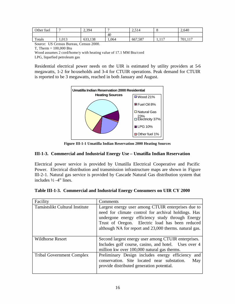
As of 2000, there are 1,013 occupied homes and 52 vacant homes on the UIR. Most homes are heated by electricity, followed by utility (natural) gas and wood. Table III-1-2 shows the current and projected residential energy use based on a 5% per decade increase in housing. The solar energy projection in Table III-1-2 assumes that 10% of home’s electricity in 2010 and 20 % in 2020 will be supplied by non-hydro solar, primarily wind. Wood is a traditional energy source for the people of the UIR, and many still prefer wood heat to other means of heating their homes. The UIR is in close proximity to the Umatilla, Wallowa-Whitman, and Malheur National forests, and many of the tribal members gather their wood supply form these forests. . Table III-1-2. Residential Energy Consumption, Umatilla Indian Reservation
No. Homes 2000
Energy Use 2000
No. Homes 2010
Energy Use 2010
No. Homes 2020
Energy Use 2020
Natural Gas 236 171,330T 248 180,000T 260 189,000 LPG 104 76,128T 109 79,934T 115 83,931T Electricity 376 286,500 289 220,200 192 146,300 Fuel oil 76 25,992T 80 27,292 84 28,656 Coal 0 0 0 0 0 0 Wood 214 73,188T 225 76,847 236 80,690 Solar 0 0 106 80,800 223 169,900
15
Other fuel 7 2,394 7 2,514 8 2,640 40
Totals 1,013 633,138 1,064 667,587 1,117 701,117 Source: US Census Bureau, Census 2000. T, Therm = 100,000 Btu Wood assumes 2 cord/home/y with heating value of 17.1 MM Btu/cord LPG, liquefied petroleum gas
Residential electrical power needs on the UIR is estimated by utility providers at 5-6 megawatts, 1-2 for ho useholds and 3-4 for CTUIR operations. Peak demand for CTUIR is reported to be 3 megawatts, reached in both January and August.
Umatilla Indian Reservation 2000 Residential Heating Sources Wood 21%
Fuel Oil 8%
Natural Gas 23% Electricity 37%
LPG 10%
Other fuel 1%
Figure III-1-1 Umatilla Indian Reservation 2000 Heating Sources
III-1-3. Commercial and Industrial Energy Use – Umatilla Indian Reservation
Electrical power service is provided by Umatilla Electrical Cooperative and Pacific Power. Electrical distribution and transmission infrastructure maps are shown in Figure III-2-1. Natural gas service is provided by Cascade Natural Gas distribution system that includes ½ -4” lines.
Table III-1-3. Commercial and Industrial Energy Consumers on UIR CY 2000
Facility Comments Tamástslikt Cultural Institute Largest energy user among CTUIR enterprises due to
need for climate control for archival holdings. Has undergone energy efficiency study through Energy Trust of Oregon. Electric load has been reduced although NA for report and 23,000 therms. natural gas.
Wildhorse Resort Second largest energy user among CTUIR enterprises. Includes golf course, casino, and hotel. Uses over 4 million kw over 100,000 natural gas therms.
Tribal Government Complex Preliminary Design includes energy efficiency and conservation. Site located near substation. May provide distributed generation potential.
16

Mission Market Located in a sheltered river valley. Excellent solar potential
Tribal Environmental Recovery Facility
Minimal power usage. Located near proposed Coyote Light industrial park.
Arrowhead Travel Plaza Power usage unknown. Altho ugh uses approximately 2400 natural gas therms.
Coyote Business Park No load at present.
Proposed new tribal government complex Nictyoway Charter School and CayUmaWa headstart.
Charter School located in refurbished community center. CayUmaWa built circa 1975 and has been remodeled several times. Load unknown
Longhouse Built 1977-78. New AC installed 2002. Natural Gas stoves and hot water heaters. Load unknown. Excellent Solar Potential
III.-1-4. Comparison of Energy Cost on CTUIR with National Average Cost
National Average Cost (Rural Utility Service 2004) Electricity $0.085 per kWh ($85.00 per MWh) Natural Gas $6.96 per thousand cubic feet or $0.696/therm
Umatilla Indian Reservation Cost Electricity (Umatilla Electrical Cooperative) $0.065 per kWh Natural Gas (Cascade Natural Gas) $0.904/therm
III-1-5. Petroleum and Transportation Energy Usage
Total petroleum usage per person per day in Oregon is estimated at 2.27 gallons (DOE/EIA-0383,2003). If the same purchasing trends hold true locally, CTUIR residents consume approximately 2,425,166 gallons of petroleum collectively per year based on 365 days per year and a 2000 population of 2927.
Average gasoline consumption per person per day in Oregon is about 0.85 gallons. Applying this State consumption figure to the UIR produces a consumption rate of 904,940 gallons per year for Reservation residents. Since this usage per day is based on an average of rural and urban areas, with a greater population density in urban areas, it is likely that rural gasoline consumption is higher.
• Arrowhead sales (2003): 4,359,767 gal diesel; 1,585,283 gal of gasoline;
17
• Located on U.S. Interstate 84 at the western base of the Blue Mountains and provides fuel for both travelers commercial and private as well as providing fuel for local consumption.
• The CTUIR’s GSA fleet includes 128 vehicles. None of these vehicles use hybrid technology and all of them run on gasoline.
• The CTUIR’s golf course has a fleet of electric golf carts.
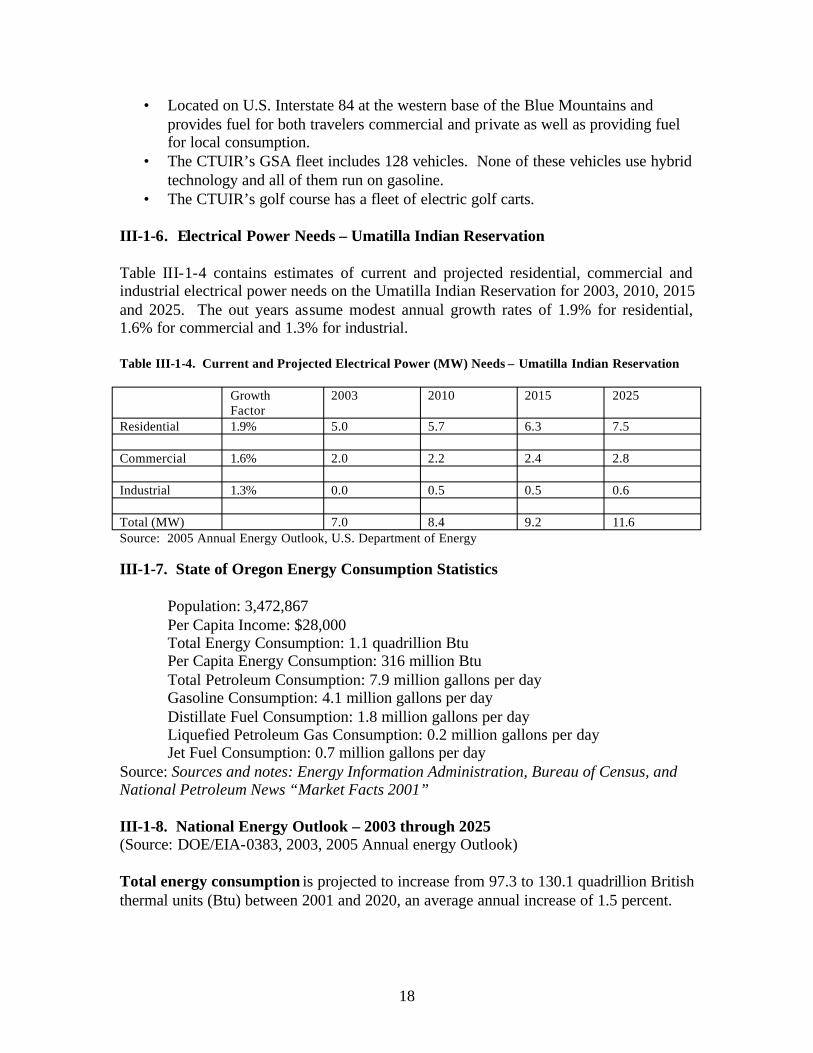
III-1-6. Electrical Power Needs – Umatilla Indian Reservation
Table III-1-4 contains estimates of current and projected residential, commercial and industrial electrical power needs on the Umatilla Indian Reservation for 2003, 2010, 2015 and 2025. The out years assume modest annual growth rates of 1.9% for residential, 1.6% for commercial and 1.3% for industrial.
Table III-1-4. Current and Projected Electrical Power (MW) Needs – Umatilla Indian Reservation
Growth Factor
2003 2010 2015 2025
Residential 1.9% 5.0 5.7 6.3 7.5
Commercial 1.6% 2.0 2.2 2.4 2.8
Industrial 1.3% 0.0 0.5 0.5 0.6
Total (MW) 7.0 8.4 9.2 11.6 Source: 2005 Annual Energy Outlook, U.S. Department of Energy
III-1-7. State of Oregon Energy Consumption Statistics
Population: 3,472,867 Per Capita Income: $28,000 Total Energy Consumption: 1.1 quadrillion Btu Per Capita Energy Consumption: 316 million Btu Total Petroleum Consumption: 7.9 million gallons per day Gasoline Consumption: 4.1 million gallons per day Distillate Fuel Consumption: 1.8 million gallons per day Liquefied Petroleum Gas Consumption: 0.2 million gallons per day Jet Fuel Consumption: 0.7 million gallons per day
Source: Sources and notes: Energy Information Administration, Bureau of Census, and National Petroleum News “Market Facts 2001”
III-1-8. National Energy Outlook – 2003 through 2025 (Source: DOE/EIA-0383, 2003, 2005 Annual energy Outlook)
Total energy consumption is projected to increase from 97.3 to 130.1 quadrillion British thermal units (Btu) between 2001 and 2020, an average annual increase of 1.5 percent.
18

Residential energy consumption is projected to grow at an average rate of 1.0 percent per year between 2001 and 2025, with the most rapid growth expected for computers, electronic equipment, and appliances.
Transportation energy demand is projected to grow at an average annual rate of 2.0 percent between 2001 and 2025, reaching 40.4 quadrillion Btu in 2020 and 44.0 quadrillion Btu by 2025. The higher level of consumption in the transportation sector results from a higher forecast of vehicle miles traveled and a lower level of vehicle efficiency.
Total electricity demand is projected to grow by 1.9 percent per year from 2001 through 2020 and 1.8 percent per year from 2001 to 2025. Rapid growth in electricity use for computers, office equipment, and a variety of electrical appliances in the residential and commercial sectors is only partially offset by improved efficiency in these and other more traditional electrical applications; however, demand growth is expected to slow as regional and national market saturation is reached for air conditioning and some other applications.
Total petroleum demand is projected to grow at an average annual rate of 1.7 percent through 2025 (reaching 29.17 million barrels per day), led by growth in the transportation sector, which is expected to account for about 74 percent of petroleum demand in 2025.
Total renewable fuel consumption, including ethanol for gasoline blending, is projected to grow at an average rate of 2.2 percent per year through 2025, primarily due to State mandates for renewable electricity generation. About 55 percent of the projected demand for renewable energy in 2025 is for electricity generation and the rest for dispersed heating and cooling, industrial uses (including CHP), and fuel blending.
Energy use per person generally declined from 1970 through the mid-1980s but began to increase as energy prices declined in the late 1980s and 1990s. Per capita energy use is projected to increase in the forecast, with growth in demand for energy services only partially offset by efficiency gains. Per capita energy use increases by 0.7 percent per year between 2001 and 2025.
Renewable technologies are projected to grow slowly because of the relatively low costs of fossil- fired generation (and high cost of renewable energy) and because competitive electricity markets favor less capital- intensive natural gas technologies over coal and base load renewable energy in the competition for new capacity.
III-1-9 References
1. Rural Utility Service, http://www.usda.gov/rus/electric/hecgp2004/application -guide -2004.doc
2. DOE/EIA – 0383,2003 3. 2005 Annual Energy Outlook, U.S. Department of Energy. 4. U.S. Bureau of Census, 2002 5. National Petroleum News, 2001 Market Facts.
19

III-2. Energy Infrastructure on Umatilla Indian Reservation
III-2-1. Electrical
The electrical energy on the reservation is provided by two suppliers, Umatilla Electrical Cooperative and Pacific Power a subsidiary of PacifiCorp who work with the regional power agency, the Bonneville Power Administration (BPA), to provide electricity on the Umatilla Indian Reservation and surrounding area. Figure III-2-1 display the electrical infrastructure on the UIR. Any three-phase electrical service could handle distribution (not transmission) of a new renewable load of a few megawatts as might be produced from wind energy.
Electricity Transmission and Distribution on the Umatilla Indian ReservationFigure III-2-1
20

BPA has a 35 Mile 230 kV line crossing the Reservation in a 100 foot wide right of way. This line is a regional transmission line that runs roughly east-west through the UIR. A long term agreement between the CTUIR and BPA has been established to accommodate this line.
The Umatilla Electric Cooperative (UEC) is a small, non-profit rural electric cooperative. As a preferred customer of the Bonneville Power Administration, Umatilla Electric Cooperative retains first right to federally owned hydroelectric resources. UEC serves approximately ½ the area of the UIR and has approximately 226 miles of line on the Reservation. UEC has a substation located at Mission. UEC primarily serves residents in the outlying areas of the Reservation. Umatilla Electrical Cooperative purchases most of the electricity they supply to the UIR and other local markets in Umatilla Co. from the northwest hydropower system.
Pacific Power is a subsidiary of PacifiCorp, a large investor owned integrated electrical power company. Pacific Power serves customers with ½ the distribution lines on the Reservation. Pacific Power serves customers from the Round Up Substation that ties into the Bonneville 230 kV line. Pacific Power serves the primary commercial load on the Reservation including the Wildhorse Resort and Casino, RV Park, Arrowhead Travel Plaza, Gulf Course and Tamástslikt Culture Institute as well as many of the more densely populated residential areas.
PacifiCorp reports the following electric energy mix it provides its customers while Table IV-2-5 shows a summary of PacifiCorp’s 8,364 MW generation capacity.
• 85.71 % energy non-renewables (coal and natural gas) • 12.89% from hydropower • 1.40 % from wind, geothermal and solar
Table III-2-5. PacifiCorp Energy Generation Summary
Thermal units (power plants, primarily coal and natural gas): Operator of 10 plants plus part owner of 6 more in Wyoming, Utah, Arizona, Colorado, Montana and Oregon.Capacity: nearly 7,169 megawatts
Hydropower: 53 facilities (dams) in Washington, Oregon, Idaho, Utah and MontanaCapacity: 1,078 megawatts
Wind: 2 facilities in Wyoming (Wyoming Wind Energy Project and Rock River I)Capacity: 91 megawatts
Geothermal: 1 facility (Blundell) Capacity: 26 megawatts
Solar: 1 facility (California) Capacity: unknown
Source: www.pacificorp.com
21
III-2-2. Natural Gas
Cascade Natural Gas (CNG) is the sole provider of natural gas service on the UIR. CNG is headquartered out of Seattle, Washington with a district office in Pendleton, Oregon. Major natural gas transmission lines run across the UIR in roughly a north south direction. The natural gas transmission lines are owned and operated by Williams of Tulsa Oklahoma. There are three Williams owned natural gas transmission lines of 30, 22, and 6 inches that cross the Umatilla Indian Reservation, the latter a lateral to Walla Walla. Chevron provides liquid petroleum products through two liquid fuel transmission lines of 6 and 8 inch and still owns a tank facility on the reservation that is currently not used due to environmental concerns.
III-2-3. Biomass Fuels
Wood is the only biomass used at this time on the UIR. Use is confined primarily to traditional activities such as but not limited to residential heating and cooking, camping, lodging material (teepee), fishing scaffolds, fish drying sheds, smokehouses, poles (fence, corrals), traditional art, and sweat lodge. The wood comes primarily from three National Forests that are in close proximity to the UIR, the Wallowa-Whitman National Forest, Malheur National Forest and the Umatilla National Forest. The CTUIR retain rights to public lands throughout their usual and accustomed territories including near fishing stations that would require use of other public lands. Some fire wood is also obtained from private lands. While there are a number of commercial suppliers of wood, many residents that use wood go to the forest and harvest their own.
III-2-4. Transportation Fuels
There is only one commercial transportation fuel station on the UIR, the Arrowhead Travel Plaza. The truck stop is owned by the CTUIR and is located along interstate I-82. The plaza provides gasoline, diesel and LPG service and is diversifying to serve all travelers. There are no biofuels currently provided by the station.
III-2-5. Other Energy Sources
There is one 1kW privately owned wind energy system on the UIR. The LPG and fuel oil that are used as residential energy and back up fuel for generators on the UIR are supplied by commercial vendors off the reservation in the nearby cities of Pendleton, Hermiston and La Grande. There are some small biodiesel efforts in the surrounding community.
III-3. Renewable Energy Economics
III-3-1. Financial Figures of Merit
An investor, energy policy analyst, or developer may use a variety of figures of merit to evaluate the financial attractiveness of a power project. The choice often depends on the
22

purpose of the analysis. However, most begin with estimates of the project’s capital cost, projected power output, and annual revenues, expenses, and deductions. A proforma earnings statement, debt redemption schedule, and statement of after-tax cash flows are typically also prepared. Annual after-tax cash flows are then compared to initial equity investment to determine available return. For another perspective, before-tax, no-debt cash flows may also be calculated and compared to the project's total cost. The four primary figures of merit are:
• Net Present Value : Net Present Value (NPV) is the sum of all years’ discounted after-tax cash flows. The NPV method is a valuable indicator because it recognizes the time value of money. Projects whose returns show positive NPVs are attractive.
• Internal Rate of Return: Internal rate of return (IRR) is defined as the discount rate at which the after-tax NPV is zero. The calculated IRR is examined to determine if it exceeds a minimally acceptable return, often called the hurdle rate. The advantage of IRR is that, unlike NPV, its percentage results allow projects of vastly different sizes to be easily compared.
• Cost of Energy: To calculate a levelized cost of energy (COE), the revenue stream of an energy project is discounted using a standard rate (or possibly the project's IRR) to yield an NPV. This NPV is levelized to an annual payment and then divided by the project’s annual energy output to yield a value in cents per kWh. The COE is often used by energy policy analysts and project evaluators to develop first-order assessments of a project’s attractiveness. The levelized COE defines the stream of revenues that minimally meets the requirements for equity return and minimum debt coverage ratio. Traditional utility revenue requirement analyses are cost-based, ie., allowed costs, expenses, and returns are added to find a stream of revenues that meet the return criteria. Market-based Independent Power Producer (IPP) and Generating Company (GenCo) analyses require trial-and-error testing to find the revenues that meet debt coverage and equity return standards, but their COEs likewise provide useful information.
• Payback Period: A payback calculation compares revenues with costs and determines the length of time required to recoup the initial investment. A Simple Payback Period is often calculated without regard to the time value of money. This figure of merit is frequently used to analyze retrofit opportunities offering incremental benefits and end-user applications.
III-3-2. Financial Structures
Four distinct ownership perspectives were identified for this analysis. Each reflects a different financial structure, financing costs, taxes, and desired rates of return. Briefly, the four ownership scenarios are:
23

• Generating Company (GenCo): The GenCo takes a market-based rate of return approach to building, owning, and operating a power plant. The company uses balance-sheet or corporate finance, where debt and equity investors hold claim to a diversified pool of corporate assets. For this reason, GenCo debt and equity are less risky than for an IPP (see below) and therefore GenCos pay lower returns. A typical GenCo capital structure consists of 35% debt at a 7.5% annual return (with no debt service reserve or letter of credit required) and 65% equity at 13% return. Although corporate finance might assume the debt to equity ratio remains constant over the project's life and principal is never repaid, it is often informative to explicitly show the effect of the project on a stand-alone financial basis. Therefore, to be conservative, the debt term is estimated as 28 years for a 30-year project, and all the debt is repaid assuming level mortgage-style payments. Flow-through accounting is used so that the corporate GenCo receives maximum benefit from accelerated depreciation and tax credits.
• Independent Power Producer (IPP): An IPP’s debt and equity investment is secured by only the one project, not by a pool of projects or other corporate assets as is the case for a GenCo. In this project finance approach, a typical capital structure is 70% debt at 8.0% annual return (based on 30-year Treasury Bill return plus a 1.5% spread) and 30% equity at a minimum 17% return. A 6-month Debt Service Reserve is maintained to limit repayment risks. Debt term for an IPP project is generally 15 years, with a level mortgage-style debt repayment schedule. (For solar and geothermal projects that are entitled to take Investment Tax Credits, a capital structure of 60% debt and 40% equity should be considered.) Flow-through accounting is used to allow equity investors to realize maximum benefit from accelerated depreciation and tax credits. IPP projects are required to meet two minimum debt coverage ratios. The first requirement is to have an operating income of no less than 1.5 times the annual debt service for the worst year. The second is to have an operating income of about 1.8 times or better for the average year. Because debt coverage is often the tightest constraint, actual IRR may be well over 17%, to perhaps 20% or more. Likewise, with good debt coverage, negative after-tax cash flows in later years of debt repayment (phantom income) are low.
• Regulated Investor-Owned Utility (IOU): The regulated IOU perspective analyzes a project with a cost-based revenue requirements approach. As described by the EPRI Technical Assessment Guide (TAG ), returns on TM investment are not set by the market, but by the regulatory system. In this calculation, operating expenses, property taxes, insurance, depreciation, and returns are summed to determine the revenue stream necessary to provide the approved return to debt and equity investors. Use of a Fixed Charge Rate is a way to approximate the levelized COE from this perspective. IOU capital structure is estimated as 47% debt at a 7.5% annual return; 6% preferred stock at 7.2%; and 47% common stock at 12.0%. Debt term and project life are both 30 years. Accelerated depreciation is normalized using a deferred tax account to spread the result over the project's lifetime. IOUs are not eligible to take an Investment Tax Credit for either solar or
24

geothermal projects. Municipal Utility (or other tax-exempt utility): The municipal utility uses an analysis approach similar to that of the IOU. Capital structure is, however, assumed to be 100% debt at 5.5% annual return, and the public utility pays neither income tax nor property tax.
III-3-3. Calculating Levelized Cost of Energy (COE)
The technique to be used for calculating levelized COE varies with ownership perspective. Two of the four ownership perspectives (IOU and Muni) employ a cost-based revenue requirements approach, while the other two use a market-based rate of return approach. The revenue requirements approach assumes a utility has a franchised service territory and, its rate of return is set by the state regulatory agency. The plant's annual expenses and cash charges are added to the allowed rate of return on the capital investment to determine revenues.
By contrast, the market-based approach (GenCo and IPP) either estimates a stream of project revenues from projections about electricity sales prices or proposes a stream as part of a competitive bid. Annual project expenses, including financing costs, are calculated and subtracted from revenues and an IRR is then calculated. The process of calculating the achieved IRR differs from the revenue requirements approach where the rate of return is pre-determined.
COEs can be calculated for both revenue requirements and rate of return approaches. When pro forma cash flows in dollars of the day are projected for both approaches, the effects of general inflation are captured in debt repayment, income taxes, and other factors. Next, revenues are net present valued in current dollars. The NPV is then levelized to current dollars and/or constant dollars using appropriate discount rates for each. These are then levelized and normalized to one unit of energy production (kWh) to calculate current and constant dollar COEs. This document cites levelized constant dollar COEs in 1997 dollars.
Table III-3-6 provides an example of the results that may be obtained for the technologies characterized in this document. The table shows levelized COE for the various renewable energy technologies assuming GenCo ownership and balance sheet finance.
25

Table III-3-6
III-3-4. Financial Model and Results
The FATE2-P (Financial Analysis Tool for Electric Energy Projects) financial analysis model was used to analyze the data provided in the Technology Characterizations. This spreadsheet model was developed by Princeton Economic Research, Inc. and the National Renewable Energy Laboratory for the U.S. Department of Energy. FATE2-P can be used for either the revenue requirements or the discounted rate of return approach. It is used by the DOE renewable energy R&D programs for its planning activities. The model is publicly available, and has been used by a number of non-DOE analysts in recent studies. Other models will produce the same results given the same inputs.
The COEs in Table III-3-1 were prepared using the FATE2-P model, assuming GenCo ownership. The results reflect a capital structure of 35% debt with a 7.5% return (with no debt service reserve or letter of credit required) and 65% equity at 13%. A 40% tax rate is assumed. Inflation was estimated at 3%, but electricity sales revenues were assumed to increase at inflation less one half percent, or 2.5%, corresponding to a real rate of -0.5%. In similar fashion, the Department of Energy's Annual Energy Outlook 1997 forecasts that retail electricity prices will decline by 0.6% real, assuming inflation of 3.1%. Anecdotal information from IPPs suggests that they also presently escalate their wholesale power prices at less than inflation.
26
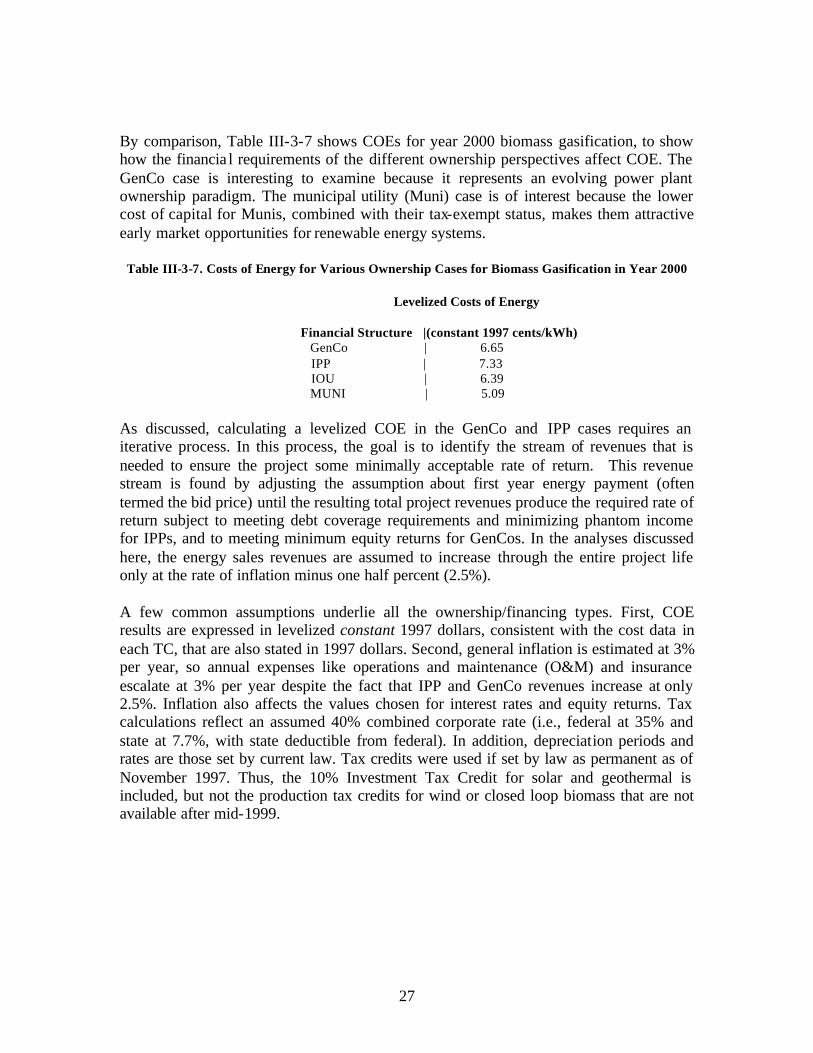
By comparison, Table III-3-7 shows COEs for year 2000 biomass gasification, to show how the financia l requirements of the different ownership perspectives affect COE. The GenCo case is interesting to examine because it represents an evolving power plant ownership paradigm. The municipal utility (Muni) case is of interest because the lower cost of capital for Munis, combined with their tax-exempt status, makes them attractive early market opportunities for renewable energy systems.
Table III-3-7. Costs of Energy for Various Ownership Cases for Biomass Gasification in Year 2000
Levelized Costs of Energy
Financial Structure |(constant 1997 cents/kWh) GenCo | 6.65 IPP | 7.33 IOU | 6.39 MUNI | 5.09
As discussed, calculating a levelized COE in the GenCo and IPP cases requires an iterative process. In this process, the goal is to identify the stream of revenues that is needed to ensure the project some minimally acceptable rate of return. This revenue stream is found by adjusting the assumption about first year energy payment (often termed the bid price) until the resulting total project revenues produce the required rate of return subject to meeting debt coverage requirements and minimizing phantom income for IPPs, and to meeting minimum equity returns for GenCos. In the analyses discussed here, the energy sales revenues are assumed to increase through the entire project life only at the rate of inflation minus one half percent (2.5%).
A few common assumptions underlie all the ownership/financing types. First, COE results are expressed in levelized constant 1997 dollars, consistent with the cost data in each TC, that are also stated in 1997 dollars. Second, general inflation is estimated at 3% per year, so annual expenses like operations and maintenance (O&M) and insurance escalate at 3% per year despite the fact that IPP and GenCo revenues increase at only 2.5%. Inflation also affects the values chosen for interest rates and equity returns. Tax calculations reflect an assumed 40% combined corporate rate (i.e., federal at 35% and state at 7.7%, with state deductible from federal). In addition, depreciation periods and rates are those set by current law. Tax credits were used if set by law as permanent as of November 1997. Thus, the 10% Investment Tax Credit for solar and geothermal is included, but not the production tax credits for wind or closed loop biomass that are not available after mid-1999.
27

IV. Renewable Energy Resources, Technologies and Economics In-and-Near the UIR
IV-1. Biomass Resources
Biomass, equated with plant matter, is a renewable natural resource produced in a mired of forms all over the earth by the process of photosynthesis. Biomass has many diverse uses, perhaps foremost is as a source of food for many different living species and as a source of oxygen for aerobes. Biomass may also be used as a raw material from which to make refined products with added value, including power, liquid fuels, and chemicals. Before technology became available to perform the conversation of the raw biomass into these refined, higher value products, biomass was largely used as a fuel for combustion. Central to determining the potential for energy production from biomass is an understanding of the location, quantities, types, and prices of biomass resources and the state of technology for its conversion into energy. The U.S. Department of Energy has a goal of increasing the use of biomass in supply the U.S. energy needs as expressed in Executive Order 13134 of August 12, 1999 is also available.
IV-1-1. Resource Availability
Biomass feedstocks are classified into five general categories: forest residues, mill residues, agricultural residues, urban wood wastes, and dedicated energy crops. Forestry is a major industry in the United States encompassing nearly 559 million acres in publicly and privately held forest lands in the continental U.S. (USDA, 1997). Nearly 16 million cubic feet of roundwood are harvested and processed annually to produce sawlogs, paper, veneers, composites and other fiber products (USDA, 1998a). The extensive forest acreage and roundwood harvest generate logging residues and provide the potential to harvest non-merchantable wood for energy. Processing of the wood into fiber products creates substantial quantities of mill residues that could potentially be used for energy. Agriculture is another major industry in the United States. Approximately 337 million acres of cropland are currently in agricultural production (USDA, 1997). Following the harvest of many of the traditional agricultural crops, residues (crop stalks) are left in the field. A portion of these residues could potent ially be collected and used for energy. Alternatively, crop acres could be used to grow dedicated energy crops. A final category of biomass feedstocks includes urban wood wastes. These wastes include yard trimmings and other wood materials that are generally disposed of in municipal solid waste (MSW) and construction/demolition (C/D) landfills. Following is a description of the potential availability of these biomass feedstocks in Oregon and in-and-near the UIR.
IV-1-1-1. Forest Residues
Forest wood residues can be grouped into the following categories- logging residues, rough, rotten, and salvable dead wood, excess saplings, and small pole trees (1). Table IV1 shows the forest wood residue supplies that could potentially be available for energy use in Oregon. They have been estimated by Walsh et al. using an updated version of a model originally developed by McQuillan et al. (1984). The McQuillan model estimates
28
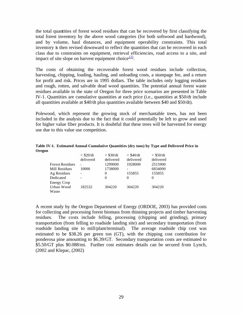
the total quantities of forest wood residues that can be recovered by first classifying the total forest inventory by the above wood categories (for both softwood and hardwood), and by volume, haul distances, and equipment operability constraints. This total inventory is then revised downward to reflect the quantities that can be recovered in each class due to constraints on equipment, retrieval efficiencies, road access to a site, and impact of site slope on harvest equipment choice (2).
The costs of obtaining the recoverable forest wood residues include collection, harvesting, chipping, loading, hauling, and unloading costs, a stumpage fee, and a return for profit and risk. Prices are in 1995 dollars. The table includes only logging residues and rough, rotten, and salvable dead wood quantities. The potential annual forest waste residues available in the state of Oregon for three price scenarios are presented in Table IV-1. Quantities are cumulative quantities at each price (i.e., quantities at $50/dt include all quantities available at $40/dt plus quantities available between $40 and $50/dt).
Polewood, which represent the growing stock of merchantable trees, has not been included in the analysis due to the fact that it could potentially be left to grow and used for higher value fiber products. It is doubtful that these trees will be harvested for energy use due to this value use competition.
Table IV-1. Estimated Annual Cumulative Quantities (dry tons) by Type and Delivered Price in Oregon
< $20/dt < $30/dt < $40/dt < $50/dt delivered delivered delivered delivered
Forest Residues - 1299000 1928000 2515900 Mill Residues 10000 1738000 - 6834000 Ag Residues - 0 155855 155855 Dedicated - 0 0 0 Energy Crop Urban Wood 182532 304220 304220 304220 Waste
A recent study by the Oregon Department of Energy (ORDOE, 2003) has provided costs for collecting and processing forest biomass from thinning projects and timber harvesting residues. The costs include felling, processing (chipping and grinding), primary transportation (from felling to roadside landing site) and secondary transportation (from roadside landing site to mill/plant/terminal). The average roadside chip cost was estimated to be $38.26 per green ton (GT), with the chipping cost contribution for ponderosa pine amounting to $6.39/GT. Secondary transportation costs are estimated to $5.50/GT plus $0.088/mi. Further cost estimates details can be secured from Lynch, (2002 and Klepac, (2002)
29

IV-1-1-2. Primary Forest Mill Residues
The quantities of mill residues generated at primary wood mills (i.e., mills producing lumber, pulp, veneers, other composite wood fiber materials) in Oregon are shown in Table IV-1 from the data compiled by the USDA Forest Service for the 1997 Resource Policy Act (RPA) Assessment (USDA, 1998a). Mill residues are classified by type and include bark; coarse residues (chunks and slabs); and fine residues (shavings and sawdust). Data is available for quantities of residues generated by residue type and on uses of residues by residue type and use category (i.e., not used, fuel, pulp, composite wood materials, etc.). The compiled USDA data (USDA, 1998a) is available at the county, state, sub region, and regional level. In cases where a county has fewer than three mills, data from multiple counties are combined to maintain the confidentiality of the data provided by individual mills. Data represent short run average quantities.
Because primary mill residues are clean, concentrated at one source, and relatively homogeneous, nearly 98 percent of all residues generated in the United States are currently used as fuel or to produce other fiber products. Of the 24.2 million dry tons of bark produced in the U.S., 2.2 percent is not used while 79.4 percent is used for fuel and 18 percent is used for such things as mulch, bedding, and charcoal. Only about 1.4 percent of the 38.7 million dry tons of coarse residues are not used. The remaining materials are used to produce pulp or composite wood products such as particle board, wafer board, and oriented strand board (78 percent) and about 13 percent are used for fuel. Of the 27.5 million dry tons of fine wood residues, approximately 55.6 percent are used for fuel, 23 percent are used to produce pulp or composite wood products, 18.7 percent are used for bedding, mulch and other such uses, and about 2.6 percent are unused.
The residues, while currently used, could potentially be available for energy use if utilities could pay a higher price for the residues than their value in their current uses. Data regarding the value of these residues in their current uses are difficult to obtain. Much of the residues used for fuel are used on site by the residue generator in low efficiency boiler systems to produce heat and steam. Anecdotal evidence suggests that these residues could be purchased for $15-25/dry ton for use in higher efficiency fuel systems. Similar anecdotal evidence suggests that residues used to produce fiber products (pulp, composite wood materials) sell for about $30-40/dry ton. The data in Table IV-1, obtained form Walsh et al. assume that the residues not currently used could potentially be available for energy uses at delivered prices of less than $20/dry ton (assuming transportation distances of less than 50 miles). For similar transportation distances, we assume that residues currently used for fuel could be available at less than $30/dry ton delivered and residues currently used for pulp, composite wood materials, mulch, bedding, and other such uses could potentially be available at delivered prices of less than $50/dry ton.
A recent study by the Oregon Department of Energy (ORDOE,2003) for Umatilla, Union and Wallowa counties characterizes wood products industry residue supply as being currently fully utilized. The wood products supply in the region is really limited to chips
30

currently sold for pulp and a small quantity of veneer cores that are sold sporadically for post and pole operations. The total quantity of chips and veneer cores generated annually in the region is 310,253 GT. The bulk of the residues are generated in La Grande, Oregon. The residue supply price is subject to fluctuations associated with markets for lumber, paper pulp, plywood and particleboard that could affect the cost-effectiveness of this supply. The cyclical nature of pulp chip prices, in particular, could affect availability of this supply. In the past, prices for clean chips from sawmills have been as high as $60/GT. Table IV-2 provides cost estimates for 2002 of wood precuts residue supply costs delivered to conversion sites.
Table IV. 2 Wood Products Residue Supply Costs Delivered to Conversion Sites.
Type Price @ Mill, $/GT Transport Cost, $/GT/mi Total Costs, $/GT* Chips 15.93 0.20 25.93 Veneer Cores 3.00 0.20 13.00
*Assumes 50 miles transport. GT, green ton.
IV-1-1-3. Agricultural Residues
Agriculture is a major activity in the United States and in and near the UIR. Among the most important crops in terms of average total acres planted from 1995 to 1997 are corn (77 million acres), wheat (72 million acres), soybeans (65 million acres), hay (60.5 million acres), cotton (15 million acres), grain sorghum (10 million acres), barley (7 million acres), oats (5 million acres), rice (3 million acres), and rye (1.5 million acres) (USDA, 1998b). After harvest, a portion of the stalks could potentially be collected for energy use.
The analysis in this paper is limited to corn stover and wheat straw. Large acreage is dedicated to soybean production, but in general, residue production is relatively small and tends to deteriorate rapidly in the field, limiting the usefulness of soybean as an energy feedstock. However, additional residue quantities could be available from this source that have not been included in this analysis. Similarly, additional residue quantities could be available if barley, oats, rice, and rye production were included. Production of some of these crops (rice in particular) tends to be concentrated in a relatively small geographic area, and thus these crops could be an important local source of resources. The quantities of corn stover and wheat straw residues that can be available in each state are estimated by first calculating the total quantities of residues produced and then calculating the total quantities that can be collected after taking into consideration quantities that must be left to maintain soil quality (i.e., maintain organic matter and prevent erosion). Residue quantities generated are estimated using grain yields, total grain production, and a ratio of residue quantity to grain yield, (3)
The net quantities of residue per acre that are available for collection are estimated by subtracting from the total residue quantity generated, the quantities of residues that must remain to maintain quality (Lightle, 1997). Quantities that must remain differ by crop type, soil type, typical weather conditions, and the tillage system used. A state average
31

was used for this analysis. In general, about 30 to 40 percent of the residues can be collected. The estimated prices of corn stover and wheat straw include the cost of collecting the residues, the premium paid to farmers to encourage participation, and transportation costs.
The cost of collecting the agricultural residues are estimated using an engineering approach. For each harvest operation, an equipment complement is defined. Using typical engineering specifications, the time per acre required to complete each operation and the cost per hour of using each piece of equipment is calculated (ASAE, 1995; NADA, 1995; USDA, 1996; Doanes, 1995). For corn stover, the analysis assumes 1x mow, 1x rake, 1x bale with a large round baler, and pickup, transport, and unloading of the bales at the side of the field where they are stored until transport to the user facility. The same operations are assumed for wheat straw minus the mowing. The operations assumed are conservative--mowing is often eliminated and the raking operation is also eliminated in some circumstances. The method used to estimate collection costs is consistent with that used by USDA to estimate the costs of producing agricultural crops (USDA, 1996).
An additional cost of $20/dry ton is added to account for the premium paid to farmers and the transportation cost from the site of production to the user facility. Currently, several companies purchase corn stover and/or wheat straw to produce bedding, insulating materials, particle board, paper, and chemicals (Gogerty, 1996). These firms typically pay $10 to $15/dry ton to farmers to compensate for any lost nutrient or environmental benefits that result from harvesting residues. The premium paid to farmers depends, in part, on transportation distance with farmers whose fields are at greater distances from the user facility receiving lower premiums. Studies have estimated that the cost of transporting giant round bales of switchgrass are $5 to $10 per dry ton for haul distances of less than 50 miles (Bhat et al, 1992; Graham et al, 1996; Noon et al, 1996). Agricultural residue bales are of similar size, weight, and density as switchgrass bales, and a similar transportation cost is assumed. This cost is similar to the reported transportation costs of facilities that utilize agricultural residues (Schechinger, 1997). Prices are in 1995 dollars. For a more detailed explanation of the methodology used to estimate agricultural residue quantities and prices, see Walsh et al, 1998.
A recent study by the Oregon Department of Energy (ORDOE,2003) has provided cost and supply estimates for agriculture residues in Northeastern Oregon. The information is presented in field-dry tons, noting that field-dry residues may contain 10-20% moisture. Table IV-3 summarizes these cost estimates. The collection cost is based on swathing costs ($6/f-d ton), baling costs ($14-15/f-d ton) and stacking costs ($5-7/f-d ton). While storage costs are not contained in the estimates for rice straw they have been estimated to be from zero for uncovered filed storage to $7-25/d-f ton for covered and storage barn. The transport costs are based on a fixed cost of $5.50/f-d ton plus $0.088/mi.
32
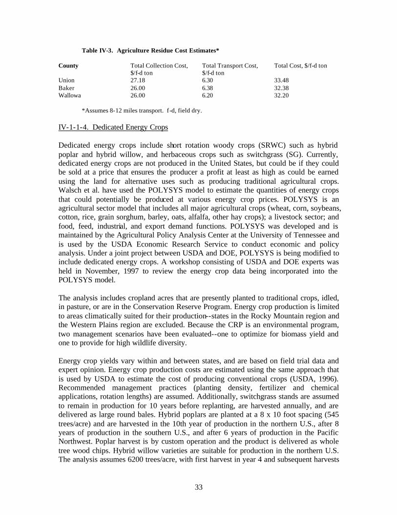
Table IV-3. Agriculture Residue Cost Estimates*
County Total Collection Cost, Total Transport Cost, Total Cost, $/f-d ton $/f-d ton $/f-d ton
Union 27.18 6.30 33.48 Baker 26.00 6.38 32.38 Wallowa 26.00 6.20 32.20
*Assumes 8-12 miles transport. f -d, field dry.
IV-1-1-4. Dedicated Energy Crops
Dedicated energy crops include short rotation woody crops (SRWC) such as hybrid poplar and hybrid willow, and herbaceous crops such as switchgrass (SG). Currently, dedicated energy crops are not produced in the United States, but could be if they could be sold at a price that ensures the producer a profit at least as high as could be earned using the land for alternative uses such as producing traditional agricultural crops. Walsch et al. have used the POLYSYS model to estimate the quantities of energy crops that could potentially be produced at various energy crop prices. POLYSYS is an agricultural sector model that includes all major agricultural crops (wheat, corn, soybeans, cotton, rice, grain sorghum, barley, oats, alfalfa, other hay crops); a livestock sector; and food, feed, industrial, and export demand functions. POLYSYS was developed and is maintained by the Agricultural Policy Analysis Center at the University of Tennessee and is used by the USDA Economic Research Service to conduct economic and policy analysis. Under a joint project between USDA and DOE, POLYSYS is being modified to include dedicated energy crops. A workshop consisting of USDA and DOE experts was held in November, 1997 to review the energy crop data being incorporated into the POLYSYS model.
The analysis includes cropland acres that are presently planted to traditional crops, idled, in pasture, or are in the Conservation Reserve Program. Energy crop production is limited to areas climatically suited for their production--states in the Rocky Mountain region and the Western Plains region are excluded. Because the CRP is an environmental program, two management scenarios have been evaluated--one to optimize for biomass yield and one to provide for high wildlife diversity.
Energy crop yields vary within and between states, and are based on field trial data and expert opinion. Energy crop production costs are estimated using the same approach that is used by USDA to estimate the cost of producing conventional crops (USDA, 1996). Recommended management practices (planting density, fertilizer and chemical applications, rotation lengths) are assumed. Additionally, switchgrass stands are assumed to remain in production for 10 years before replanting, are harvested annually, and are delivered as large round bales. Hybrid poplars are planted at a 8 x 10 foot spacing (545 trees/acre) and are harvested in the 10th year of production in the northern U.S., after 8 years of production in the southern U.S., and after 6 years of production in the Pacific Northwest. Poplar harvest is by custom operation and the product is delivered as whole tree wood chips. Hybrid willow varieties are suitable for production in the northern U.S. The analysis assumes 6200 trees/acre, with first harvest in year 4 and subsequent harvests
33
every three years for a total of 7 harvests before replanting is necessary. Willow is delivered as whole tree chips.
The estimated quantities of energy crops are those that could potentially be produced at a profit at least as great as could be earned producing traditiona l crops on the same acres, given the assumed energy crop yield and production costs, and the 1999 USDA baseline production costs, yields, and traditional crop prices (USDA, 1999b). In the U.S., switchgrass production dominates hybrid poplar and willow production at the equivalent (on an MBTU basis) market prices. The POLYSYS model estimates the farmgate price; an average transportation cost of $8/dt is added to determine the delivered price. Prices are in $1997. For a more detailed explanation of the methodology used to estimate dedicated energy crop prices and quantities, see Walsh et al, 1998 and de la Torre Ugarte et al, 1999.
IV-1-1-5. Urban Wood Wastes
Urban wood wastes include yard trimmings, site clearing wastes, pallets, wood packaging, and other miscellaneous commercial and household wood wastes that are generally disposed of at municipal solid waste (MSW) landfills and demolition and construction wastes that are generally disposed of in construction/demolition (C/D) landfills. Data regarding quantities of these wood wastes is difficult to find and price information is even rarer. Additionally, definitions differ by states. Some states collect data on total wastes deposited at each MSW and C/D landfill in their states, and in some states, the quantities are further categorized by type (i.e., wood, paper and cardboard, plastics, etc.). However, not all states collect this data. Therefore, the quantities presented are crude estimates based on survey data (Glenn, 1998; Bush et al, 1997; Araman et al, 1997).
For municipal solid wastes (MSW) a survey by Glenn, 1998 is used to estimate total MSW generated by state. These quantities are adjusted slightly to correspond to regional MSW quantities that are land-filled as estimated by a survey conducted by Araman et al, 1997. Using the Araman survey, the total amount of wood contained in land-filled MSW is estimated. According to this survey, about 6 percent of municipal solid waste in the Midwest is wood, with 8 percent of the MSW being wood in the South, 6.6 percent being wood in the Northeast and 7.3 percent being wood in the West. Estimated quantities were in wet tons; they were corrected to dry tons by assuming 15 percent moisture content by weight.
To estimate construction and demolition wastes (C/D), the Glenn study and the Bush et al, 1997 survey were used. The Glenn study provided the number of C/D landfills by state, and the Bush et al survey provided the average quantity of waste received per C/D landfill by region as well as the regional percent of the waste that was wood. According to the Bush et al survey, C/D landfills in the Midwest receive an average 25,700 tons of waste per year with 46 percent of that quantity being wood. In the South, C/D landfills receive an average 36,500 tons of waste/yr with 39 percent being wood. Northeastern C/D landfills receive an average 13,700 tons of waste/yr with 21 percent being wood and Western C/D landfills receive an average 28,800 tons of waste/yr with 18 percent being
34
wood. Estimated quantities were in wet tons; they were corrected to dry tons by assuming 15 percent moisture content by weight.
Yard trimmings taken directly to a compost facility rather than land-filled, were estimated from the Glenn study. This estimate was made by multiplying the number of compost facilities in each state by the national average tons of material received by site (2750 tons). The total compost material was then corrected for the percent that is yard trimmings (assumed to be 80 percent) and for the quantity that is wood (assumed to be 90 percent). Quantities were corrected to dry tons by assuming 40 percent moisture by weight.
In an effort to reduce the quantities of waste materials that are land-filled, most states actively encourage the recycling of wastes. Quantities and prices of recycled wood wastes are not readily available. However, the Araman and Bush surveys report limited data on the recycling of wood wastes at MSW and C/D sites. They report that in the South, approximately 36 percent of C/D landfills and 50 percent of MSW landfills operate a wood/yard waste recycling facility and that about 34 percent of the wood at C/D landfills and 39 percent of the wood at MSW landfills is recycled. In the Midwest, about 31 percent of the MSW and 25 percent of the C/D landfills operate wood recycling facilities with 16 percent of the MSW wood and 1 percent of the C/D wood is recycled. In the West, 27 percent of the MSW and C/D landfills operate wood recycling facilities and recycle 25 percent each of their wood. In the Northeast, 39 percent of the MSW and 28 percent of the C/D landfills operate wood recycling facilities and recycle 39 percent of the MSW wood and 28 percent of the C/D wastes.
The surveys do not report the use of total recycled wood, but do report the uses of recycled pallets which represent about 7 percent of the total wood and 4 percent of the recycled wood at C/D landfills and about 24 percent of the total wood and about 13 percent of the recycled wood at MSW landfills. At C/D landfills, about 14 percent of the recycled pallets are re-used as pallets, about 39 percent are used as fuel, and the remainder is used for other purposes such as mulch and composting. About 69 percent of the recyclers reported that they gave away the pallet material. Of those selling the material, the mean sale price was $11.01/ton and the median sale price was $10.50/ton. At MSW landfills, about 3 percent of the recycled pallets are re-used as pallets, about 41 percent are used as fuel, and the remainder is used for other purposes such as mulch and composting. About 58 percent of the C/D recyclers reported that they gave away the pallet material. Of those selling the material, the mean sale price was $13.17/ton and the median sale price was $10.67/ton. Transportation costs must still be added to the sale price. Given the lack of information regarding prices, we assumed that of the total quantity available, 60 percent could be available at less than $20/dry ton and that the remaining quantities could be available at less than $30/dry ton. Table 5 presents the estimated annual cumulative quantities of urban wood wastes for the state of Oregon.
35

IV-1-2. Summary
Table IV-1 summarizes estimates by Walsch et al. on the total annual cumulative quantities of biomass resources available in the state of Oregon at a specific delivered price. It is estimated that substantial quantities of biomass (10 million dry tons) could be available annually at prices of less that $50/dt delivered. However, several caveats should be noted. There is a great deal of uncertainty surrounding some of the estimates. For example, while there is substantial confidence in the estimated quantities of mill residues available by state, there is a great deal of uncertainty about the estimated prices of these residues. The value of these feedstocks in their current uses is speculative and based solely on anecdotal discussions. Given that the feedstock is already being used--much of it under contract or in-house by the generator of the waste--energy facilities may need to pay a higher price than assumed to obtain the feedstock. Additionally, both the quantity and price of urban wastes are highly speculative. The analysis is based solely on one national study and regional averages taken from two additional surveys. There is no indication of the quality of the material present (i.e., whether the wood is contaminated with chemicals, etc.). Because of the ways in which the surveys were conducted, there may be double counting of some quantities (i.e., MSW may contain yard trimmings and C/D wastes as well).
Additionally, the analysis assumes that the majority of this urban wood is available for a minimal fee, with much of the cost resulting from transportation. Other industries have discovered that once a market is established, these "waste materials" become more valuable and are no longer available at minimal price. This situation could also happen with urban wastes used for energy if a steady customer becomes available. It should also be noted however, that some studies indicate that greater qua ntities of urban wastes are available, and are available at lower prices, than are assumed in this analysis (Wiltsee, 1998). Given the high level of uncertainty surrounding the quantity and price estimates of urban wastes and mill residues, and the fact that these wastes are estimated to be the least cost feedstocks available, they should be viewed with caution until a more detailed analysis is completed.
The estimates by Walsch et al. has assumed that substantial quantities of dead forest wood could be harvested. The harvest of deadwood is a particularly dangerous activity and not one relished by most foresters. Additionally, large polewood trees represent the growing stock of trees, that if left for sufficient time, could be harvested for higher value uses. These opportunity costs have not been considered. And, the sustainability of removing these forest resources has not been thoroughly analyzed.
The price of agricultural residues are high largely because of the small quantities that can be sustained and removed on a per acre basis. Improvements in the collection/transport technologies and the ability to sustain larger quantities (due to a shift in no-till site preparation practices for example) could increase quantities and decrease prices over time. Also, the inclusion of some of the minor grain crops (i.e., barley, oats, rye, rice) and soybeans could increase the total quantities of agricultural residues available by state.
36

However, further elucidation of quantities that can sustainably be removed might lower available quantities.
Dedicated energy crops (i.e., switchgrass and short rotation wood crops) are not currently produced--the estimates by Walsch et al. are based on estimates of yield, production costs, and profitability of alternative crops that could be produced on the same land. Improving yields and decreasing production costs through improved harvest and transport technologies could increase available quantities at lower costs.
The estimates have assumed a transportation cost of $8/dry ton for most feedstocks. This cost is based on a typical cost of transporting materials (i.e., switchgrass bales and wood chips) for less than 50 miles (Graham et al, 1996; Bhat et al, 1992; Noon et al, 1996). Finally, the analysis is conducted at a state level and the distribution of biomass resources within the state is not specifically considered. We have simply assumed that the feedstock is available within 50 miles of a user facility. This may not be the case which would result either in the cost of the feedstock being higher to a user facility due to increased transportation costs, or the quantities of available feedstock being lower to a user facility if the material is simply too far away from the end-user site to be practical to obtain. Biomass resource assessments are needed at a lower aggregation level than the state.
IV-1-3. References
1. American Society of Agricultural Engineers, Standards 1995-Standards, Engineering Practices, and Data, 1995.
2. P.A. Araman, R.J. Bush, and V.S. Reddy, Municipal Solid Waste Landfills and Wood Pallets --What's Happening in the U.S., Pallet Enterprise, March 1997, pp. 50-56.
3. M.B. Bhat, B.C. English, and M. Ojo, Regional Costs of Transporting Biomass Feedstocks, Liquid Fuels From Renewable Resources, John S. Cundiff (ed.), American Society of Agricultural Engineers, St. Joseph, MI, December 1992.
4. R.J. Bush, V.S. Reddy, and P.A. Araman, Construction and Demolition Landfills and Wood Pallets--What's Happening in the U.S., Pallet Enterprise, March 1997, pp. 27-31.
5. D.G. de la Torre Ugarte, S.P. Slinsky, and D.E. Ray, The Economic Impacts of Biomass Crop Production on the U.S. Agriculture Sector, University of Tennessee Agricultural Policy Analysis Center, Knoxville, TN, July 1999, Draft Document.
6. Doane's Agricultural Report, Estimated Machinery Operating Costs, 1995 , Vol. 58, No. 15-5, April 14, 1995.
7. J. Glenn, The State of Garbage, BioCycle, April 1998, pp. 32-43. 8. R. Gogerty, Crop Leftovers: More Uses, More Value, Resource: Engineering and Technology for a
Sustainable World, Vol. 3, No. 7, July 1996. 9. R.L. Graham, W. Liu, H.I. Jager, B.C. English, C.E. Noon, and M.J. Daly, A Regional-Scale GIS-
Based Modeling System for Evaluating the Potential Costs and Supplies of Biomass From Biomass Crops, in Proceedings of Bioenergy '96 - The Seventh National Bioenergy Conference, Nashville, TN, September 15-20, 1996, Southeastern Regional Biomass Energy Program, pp. 444-450, 1996.
10. W.G. Heid, Jr., Turning Great Plains Crop Residues and Other Products into Energy, U.S. Department of Agriculture, Economic Research Service, Agricultural Economic Report No. 523, Washington, DC, November 1984.
11. D.T. Lightle, A Soil Conditioning Index for Cropland Management Systems (Draft), U.S. Department of Agriculture, Natural Resources Conservation Service, National Soil Survey Center, April 1997.
37
12. A. McQuillan, K. Skog, T. Nagle, and R. Loveless, Marginal Cost Supply Curves for Utilizing Forest Waste Wood in the United States, Unpublished Manuscript, University of Montana, Missoula, February 1984.
13. NEOS Corporation, Non-synthetic Cellulosic Textile Feedstock Resource Assessment, Southeastern Regional Biomass Energy Program, Muscle Shoals, AL, July 1998.
14. C.E. Noon, M.J. Daly, R.L. Graham, and F.B. Zahn, Transportation and Site Location Analysis for Regional Integrated Biomass Assessment (RIBA), in Proceedings of Bioenergy '96 - The Seventh National Bioenergy Conference, Nashville, TN, September 15-20, 1996, Southeastern Regional Biomass Energy Program, pp. 487-493, 1996.
15. North American Dealers Association, Official Guide--Tractors and Farm Equipment, 1995. 16. T. Schechinger, Great Lakes Chemical Corporation, personal communication, 1997. 17. U.S. Department of Agricultural, National Agricultural Statistics Service, World Agricultural Outlook
Board, USDA Agricultural Baseline Projections to 2009 , WAOB-99-1, Washington, DC, February 1999.
18. U.S. Department of Agriculture, Forest Service, Forest Inventory and Analysis Timber Product Output Database Retrieval System, (http://srsfia.usfs.msstate.edu/rpa/tpo), 1998a.
19. U.S. Department of Agriculture, National Agricultural Statistical Service, Crop Production Summary, Washington, DC, January 1998b.
20. U.S. Department of Agriculture, Economic Research Service, Agricultural Resources and Environmental Indicators, 1996-1997, Agricultural Handbook No. 712, Washington, DC, July 1997.
21. U.S. Department of Agriculture, Economic Research Service, Economic Indicators of the Farm Sector: Costs of Production--Major Field Crops, 1995, Washington, DC, 1996.
22. M.E. Walsh, R.L. Perlack, D.A. Becker, A. Turhollow, and R.L. Graham, Evolution of the Fuel Ethanol Industry: Feedstock Availability and Price, Oak Ridge National Laboratory, Oak Ridge, TN, April 21, 1998, Draft Document.
23. G. Wiltsee, Urban Wood Waste Resources in 30 US Metropolitan Areas, Appel Consultants, Inc., Valencia, CA, 1998.
24. Lynch, D.L. and K. H. Mackes, “Evaluating Costs Associated with Fuel Hazard Reduction and Forest Restoration Projects in Colorado, Fort Collins, Colorado: Department of Forest Sciences, Colorado State University, 2002.
25. Klepac, J.G. and R.B. Rummer, Smallwood Logging Production and Costs: Mechanized vs. Manual, Chicago, Illinois: ASAE International Meeting July 28-31, 2002, Paper No.l 025007.
38

Bio Pellet FuelIV-2.
IV-2-1. Background
Biomass is a form of the sun’s energy. Biomass is one of the oldest harnessed forms of energy by mankind. For the most part and still to a large extent today, the utilization of this source of energy depends upon burning the biomass and utilizing the heat released in the combustion process. This heat can be used as is or converted into electricity or mechanical energy.
Recognizing that biomass is a solid as is the pellet fuels made from it, one must ask why the bother with making pellets. Convenience and practicality stand-out as the principal reasons for pellets although one can make some arguments that there is value added to the biomass through tailoring the composition and physical properties of the pellet. Some forms of biomass (e.g., large trees, brier bushes, tree bark, grass, and fine sawdust) are difficult to transport and handle as well as feed to a combustion device. The shape, size as well as physical and chemical properties of the pellet may also be controlled and/or alter in the process of pellet manufacture such that it adds value to the product, enhancing its burning and handling characteristics.
A brief history of the pellet fuel industry in North America is as follows:
• In the 1970's the first pellet plant in North America was built in Brownsville, Oregon, to supply wood pellet fuel for commercial and industrial purposes.
• In 1983 the first residential wood pellet stoves were sold in North America. • In the 1990's Sweden began producing and using wood pellets for fuel. • By 1993-94, 350,000 pellet stoves are being used. • By 1996 there are more than 20 pellet stove manufacturers and 80 pellet mills
manufacturing high quality fuel. Approximately one million tons of wood pellets are heating residential homes throughout North America.
• Internationally- Sweden's annual consumption of pellet fuel surpasses that of the United States.
• 1997 - Nearly 500,000 pellet stoves are heating homes throughout North America.
Pellet fuels from biomass are a renewable sources of energy as is wood, hydroelectric power, and solar. The non-renewable sources of energy are the fossil fuels such as oil, coal, natural gas and electricity. For the most part electricity is a non-renewable energy source since over 73% is produced from non-renewable fuels such as coal, oil, gas and nuclear materials. The burning of fossil fuels produces high quantities of carbon dioxide gas that contributes to the "greenhouse effect". While the decay or combustion of
39

"biomass" (primarily trees and other plants) also produces carbon dioxide, it has always been a part of a natural cycle. In that cycle the released carbon dioxide gas is reabsorbed by the growing biomass. In the study "Power Surge: the Status and Near-Term Potential of Renewable Energy Technologies" they found that if biomass (wood burning) is used as a supplement to the fossil fuels, the atmospheric effect is essentially zero. In fact, they claim it may actually result in a slight improvement, a much better situation than if additional fossil fuels are burned.
While woodstoves of the past produced considerable smoke and particulate matter, the new EPA Phase Il stoves produce almost no smoke. The old conventional woodstoves emitted between 30 and 80 grams of particulate matter (smoke) per hour, while the new certified wood stoves have reduced emissions to between 3 to 6 grams per hour, a reduction of over 90%. The EPA concludes that control of the greenhouse effect could be helped if more homes reduced their use of fossil fuels and relied more on wood and biomass for heat and energy sources.
IV-2-2. Resource Assessment
The biomass resource assessment has undertaken the effort to as accurately as possible, within the limits of resources available under this project, to identify the different types and amounts of biomass that are in and near to the UIR and the availability and suitability of these materials as a feedstock from which to prepare pellet fuel. The different sources of biomass that have been identified include 1) agriculture crops, residues and byproducts, 2) forest, forest byproducts and residues, 3) residential and municipal waste, and 4) other.
IV-2-2-1. Agriculture crops, residues and byproducts
Table IV-4 shows the estimated quantity of agriculture crop as biomass that can be produced within and near the Umatilla Indian Reservation. The estimate is based on tillable land and agriculture practices used in the area and distinguish between a crop being raised primarily for biomass usage or a crop being produced primarily for another use that has biomass byproduct that could be used as a fuel.
Table IV-4. Estimated Available from Agriculture Crop Residues for Pellet Fuel Manufacture (2002)
Primary Byproduct Location Tillable Area Crop Crop Yeild Ac/Yr Total Yield
acres UIR 0 corn stover 0 0 UIR 29,974 wheat straw 2 59,948 UIR 0 rape seed residue 2 0 UIR 0 mustard residue 2 0 UIR 0 perrenial residue 0 0 Um. County 2,295 corn stover 5 11,475 Um. County 264,260 wheat straw 2 528,520 Um. County 9,402 barley straw 2 18,800 Um. County 0 rape seed residue 2 0 Um. County 48,577 hay none 0 0
40

Um. County 1,240 potato residue 0.5 620 Um. County NR mustard residue 2 0 Um. County NR perrenial residue 3 0 Morrow Co. 4,083 corn stover 5 20,415 Morrow Co. 132,309 wheat straw 2 264,618 Morrow Co. 15,342 potato residue 0.5 7,671 Morrow Co. 26,850 hay none 0 0 Morrow Co. NR rape seed residue 2 0 Morrow Co. NR mustard residue 2 0 Morrow Co. NR perrenial residue 3 0
Table IV-5. Crop Production Acreage (2002)
County Total Crop Land (Ac) Harvested Crop Land (Ac)
Umatilla County 749,666 396,024 Morrow County 464,957 212,531 Umatilla Indian Reservation 59,949 29,974*
IV-2-2-2. Forest crops, byproducts and residues
Table IV-6-1 below provides estimates of available and sustainable oven dried tons (odt) of biomass from forests in and near the Umatilla Indian Reservation for pellet fuel manufacture. Primary assumes 5 odt per year while secondary assumes 2 odt per year.
Table IV-6-1. Estimated Annual Available Biomass for Pellet Fuel Manufacture (Oregon DOE, 2003)
Location Area, acres Primary(odt) Secondary(odt) UIR 50,000 est.UNF 1,408,000
WWNF 2,394,000MNF na
250,000 100,000 7,040,000 2,816,000
11,970,000 4,788,000 na na
IV-2-3. Pellet Fuel Technology – Manufacture and Uses
Pellets are biomass materials, that is, products of commonly grown plants and trees. The most common residential pellets are made from sawdust and ground wood chips, which are waste materials from trees used to make furniture, lumber, and other products. Resins and binders (lignin) occurring naturally in the sawdust hold wood pellets together, so they usually contain no additives. Nut hulls and other materials are pelletized in some areas, and unprocessed shelled corn and fruit pits can be burned in a few pellet stove designs. Your fuel of choice and its price may depend on the waste biomass most available to pellet mills in your region. In turn, your choice of appliance design depends on the fuel available.
Wood Pellets. All pellets are not the same. Pellets are made with different combinations and types of wood. There are over 70 different companies in the
41
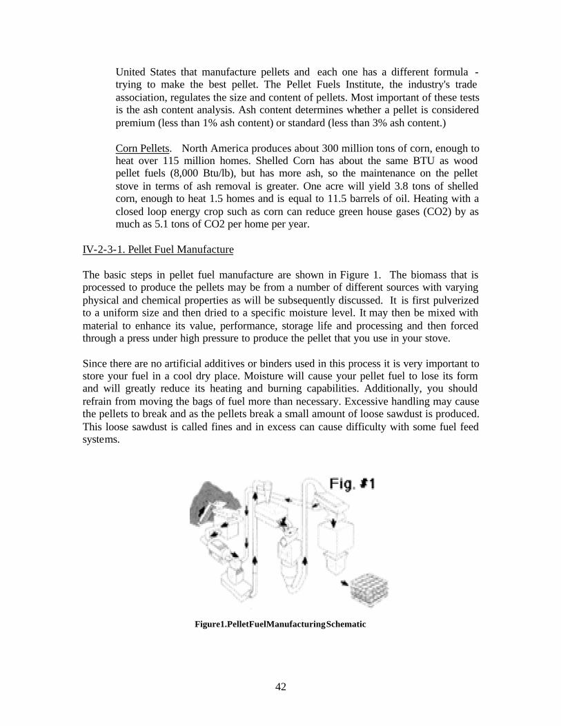
United States that manufacture pellets and each one has a different formula trying to make the best pellet. The Pellet Fuels Institute, the industry's trade association, regulates the size and content of pellets. Most important of these tests is the ash content analysis. Ash content determines whether a pellet is considered premium (less than 1% ash content) or standard (less than 3% ash content.)
Corn Pellets. North America produces about 300 million tons of corn, enough to heat over 115 million homes. Shelled Corn has about the same BTU as wood pellet fuels (8,000 Btu/lb), but has more ash, so the maintenance on the pellet stove in terms of ash removal is greater. One acre will yield 3.8 tons of shelled corn, enough to heat 1.5 homes and is equal to 11.5 barrels of oil. Heating with a closed loop energy crop such as corn can reduce green house gases (CO2) by as much as 5.1 tons of CO2 per home per year.
IV-2-3-1. Pellet Fuel Manufacture
The basic steps in pellet fuel manufacture are shown in Figure 1. The biomass that is processed to produce the pellets may be from a number of different sources with varying physical and chemical properties as will be subsequently discussed. It is first pulverized to a uniform size and then dried to a specific moisture level. It may then be mixed with material to enhance its value, performance, storage life and processing and then forced through a press under high pressure to produce the pellet that you use in your stove.
Since there are no artificial additives or binders used in this process it is very important to store your fuel in a cool dry place. Moisture will cause your pellet fuel to lose its form and will greatly reduce its heating and burning capabilities. Additionally, you should refrain from moving the bags of fuel more than necessary. Excessive handling may cause the pellets to break and as the pellets break a small amount of loose sawdust is produced. This loose sawdust is called fines and in excess can cause difficulty with some fuel feed systems.
Figure1.PelletFuelManufacturingSchematic
42

IV-2-3-2. Fuel Pellet Properties and Specifications
Common Characteristics : Although the chemical constituents and moisture content of different biomass materials vary, the Pellet Fuel Institute (PFI) has identified common characteristics and developed fuel standards. These voluntary industry standards assure as much uniformity in the final product as is possible for naturally grown materials that become processed, but not refined fuel. PFI graded fuel must meet tests for:
• Density; consistent hardness and energy content (minimum 40 pounds/ cubic foot)
• Dimensions; length (1 1/2" maximum) and diameter (1/4"or 5/16") to assure" predictable fuel amounts and to prevent fuel jamming
• Fines; limited amount of sawdust from pellet breakdown to avoid dust while loading and problems with pellet flow during operation (amount of fines passing through 1/8" screen no more than 0.5% by weight)
• Chlorides; limited salt content (no more than 300 parts per million) to avoid stove or vent rusting
• Ash content; important factor in maintenance frequency; premium (less than 1% ash content) or standard (less than 3% ash content)
Standard versus premium grade : All of the measurable characteristics defined by PFI standards are the same for both fuel grades except ash content. Standard grade pellet fuel (up to 3% ash content) is usually derived from materials which result in more residual ash, such as sawdust containing tree bark (which contains more impurities) or agricultural residues like nut hulls. Standard pellets should only be used in stoves designated for their use. Premium grade pellet fuel (less than 1% ash content) is usually produced from hardwood or softwood sawdust containing no tree bark. Ash content varies in premium fuels from about 0.3% in some western softwoods to about 0.7% in eastern hardwoods. Premium pellets, which make up over 95% of current pellet production, can generally be burned in stoves calling for either standard or premium fuel. Increased availability of standard fuel is anticipated as stove designs continue to improve ash tolerance. Ash content determines fuel grade because of its role in maintenance frequency. It is the prime factor that determines maintenance frequency of ash removal from the appliance and venting system. In early pellet stove designs, fuel compatibility was the critical factor that determined whether a stove worked well or not. Fuel grade and specific ash content within a fuel grade are still to be considered, but advances in pellet stove technology are making fuel choice wider and easier. The size of the ash drawer, fuel feed and grate design, proper venting, correct operation and maintenance all play a part in maintenance frequency. The experienced pellet stove professional is the best source of information about stove and fuel compatibility.
Other differences between fuel types and brands : There are a number of variations in pellet fuels that are not included in PFI standards. For example, Btu (heat) content may range from just under 8,000 to almost 9,000 Btu/lb, depending upon species and region of the country. Other characteristics like trace minerals in pellet raw materials vary not only from region to region, but even in close by growing areas. Some trace minerals promote
43
clinkering, the formation of clumps of fused ash that can block air inlets in the burn pot. A fuel's tendency to form clinkers in a stove cannot be predicted by laboratory analysis both because of variations in the raw materials and the different burning conditions that affect the process. Clinkering can increase routine maintenance, but professional recommendations for matching available fuels to stove design can minimize the problem. Pellet mills strive for consistency despite the nature of the raw material. Slight variations in fuel even from bag to bag are inevitable, but the differences are usually insignificant and much smaller than found in the original raw material before processing.
Ash Content Ash content in pellet fuel can be measured by weight and by vo lume using several methods. The most common measurement is ash content by weight. This is the measurement that the Pellet Fuels Institute uses in determining the ash content of the various pellet fuels currently manufactured. This measurement is the total weight of all non-combustibles in a sample of pellets, expressed as a percentage of weight of the total sample, before it is burned. This is an effective measurement, but it does not allow for variances in ash characteristics (i.e., composition and physical properties) of the different species of wood used in manufacturing pellet fuel.
Some wood species have ash characteristics with light, flake-like shapes. This type of ash, while lighter, will have considerably more volume and will not stay in the burn pot and ash containment system as easily. This fly-ash means larger ash deposits throughout the stove, (heat exchanger, ash traps, blowers, exhaust system, etc.) requiring more frequent cleaning of the burn pot and the entire exhaust system.
Simply stated, if we burn equal amounts of two different species of wood pellet fuel, the fuel with a grainy type of ash could fill a quart jar one-quarter full and the fuel with a fluffy type of ash could fill a quart jar completely full. The two samples could still weigh the same or nearly so, whereas, if samples were measured by weight alone, the weight comparisons might indicate both fuels were low ash content fuels. However, we all know that high ash will have a greater impact on the efficiency of the burn in the burn pot by reducing air flow, and require more extensive maintenance than a pellet with a low volume of ash. Additionally, ash collection on the heat exchanger tubes will dramatically reduce the ability of the heat exchanger to transfer the heat from the burning pellets into useable BTUs to heat your home. This difference in ash content measured by volume instead of weight can account for dramatic differences in pellet quality, even though their comparative Pellet Fuel Institute ratings are similar.
Clinkers This term refers to the formation of lava- like pieces of rock in the burn pot of your pellet stove. Clinkers can look like small or large pieces of lava rock. Clinkers can take the shape of the burn pot and actually form air passageways that cause the clinker to look like a honeycomb-type rock formation.
Minerals and salts are absorbed from the soil through the trees root system. When wood waste from the processing of trees into lumber is turned into pellet fuel, these inert minerals and salts remain entrenched in the wood fiber. When these non-combustibles are
44
exposed to the high burning temperatures of the pellet burning appliance, they melt and form together. This process is also known as ash fusion.
The temperature at which non-combustibles liquefy and form together is referred to as the ash fusion temperature. Depending on the type of minerals and salts contained in wood fibers, this temperature can range from 1100 degrees to 2400 degrees Fahrenheit. Recently the industry has observed that several brands of pellet fuel have a salt and mineral composition that enables ash fusion to occur at lower temperatures, causing severe clinkering. High alkali metal content in the pellet lowers the ash fusion temperature. Another side effect of fuels that have higher salt content is the creation of a corrosive atmosphere in the burn chamber, reducing the life expectancy and effectiveness of pellet stoves. If you are dealing strictly with ash fusion, the greatest problem is that you must remove the clinker from the burn pot with a pair of tongs to prevent a reduction in burn efficiency.
Some people relate ash fusion to pellet fuel being "dirty" or containing "dirt." Nothing could be closer, yet further from the truth! Yes, minerals and salts are commonly called dirt, but these are inside the wood fiber itself and no fuel manufacturer is capable of removing silicates (minerals and salts) from inside the wood fibers. This should not be confused with scooping up dirt along with raw materials in the manufacturing process, which if allowed to occur will cause massive clinkering.
Fuel Additives. The use of additives in pellet fuel has drawn attention and criticism. Some manufacturers of pellet fuel use additives in their pellet manufacturing process. Of the many additives used, polyethylene plastic and harsh industrial chemicals are the most common. Polyethylene plastic additives are used by some manufacturers for several reasons. The most important reason plastic additives are used in the pellet manufacturing process is to give additional lubrication to pellet dies. This additional lubrication can improve the production capacity of each pellet mill die by allowing raw material to pass through with less friction and heat. Additionally, polyethylene plastic additives are used to seal the pellet surface and reduce the fines content of the fuel.
Harsh industrial chemical additives are also used by some manufacturers as die lubricants and to reduce fines content by sealing the pellet. An additional reason these additives are used is to control the ash fusion temperature (clinkering) experienced in burning most pellet fuels. The chemical additives raise the ash fusion temperature in an attempt to reduce the amount of clinkering. These chemicals are sometimes used in large industrial facilities to enhance the performance of large steam boilers.
Regarding additives, some manufactures contend that high quality, low dust content pellets can be produced safely in an environmentally friendly manner without the use of polyethylene or chemical additives. The use of additives will draw negative attention to our industry and destroy the confidence our customers place in our industry to keep products safe, natural and environmentally friendly, especially if we have deceived them and not disclosed the use of additives in our pellet products.
45

Fines Content. Fines are a byproduct of the pellet manufacturing process. Each bag of pellet fuel contains residual wood fibers (commonly called dust, fines or partial pellets). We refer to this as fines content. The standard set by the PFI (Pellet Fuels Institute) for fines content in a premium pellet fuel is less than 1 percent by weight. This means for each 40 pounds of pellets, you should receive no more than 0.4 pounds (6.4 ounces) of fines.
Fines in pellet fuel can occur several ways. Fines are generated in the handling and shipping process. There are two ends to each pellet. The ends of the pellet are the most vulnerable to flaking or breaking up, which will create fines in the bag of pellets. Hand ling of pellets during the stacking and un-stacking process may create fines due to pellet ends rubbing together and breaking up. Shipping, binding pallets of pellets with straps to the truck or trailer, walking down the load to tarp and un-tarp each load of pellets and the bumping, bouncing and shifting that occur during the transportation of pellet fuel can cause pellets to break up, resulting in greater fines content in a bag of pellets. Additionally, fines can occur from moisture entering the bag.
Excessive fines can be controlled through proper cleaning of pellets before they are packaged. Pellet manufacturers have their own systems for fines removal before the pellets are sealed in bags. Fines content can be minimized by changing the raw material blends in the manufacturing process. Using aged raw material can give the pellets a deeper brown color and a minimal content of fines. Polyethylene plastic additives can be used as a binding agent to reduce fines. However, various governmental agencies and customers object strongly to burning polyethylene plastic and other harsh chemical additives in a stove designed to clean up the air we breathe and improve our environment.
Residential Pellet Fuel Standards (Source PFI, 1995) The Pellet Fuels Institute (PFI) has established national standards for residential pellet fuel. The fuel quality certification is the responsibility of the pellet manufacturer. Two fuel grades have been established, premium and standard. Five fuel characteristics are prescribed in the grades as shown in the table below. The only difference between the two grades is in the inorganic ash content, with the premium grade requiring the ash to be less than 1% while the standard grade requires less than 3%.
Property Premium Grade Standard Gr ade 1. Bulk Density/Cubic Ft. Not less than 40 lbs. Not less than 40 lbs.
2. Dimensions Diameter ¼ inch to 5/16 inch Diameter ¼ inch to 5/16 inch
Not more than 0.5% by Not more than 0.5% by 3. Fines weight weight
shall pass a 1/8 screen shall pass a 1/8 screen 4. Inorganic Ash Less than 1% Less than 3%
5. Length None longer than 1.5 inches None longer than 1.5 inches
Sodium (salt) may cause unacceptable corrosion if present in elevated levels. Natural wood uncontaminated with salt will have less than 300 ppm of water soluble sodium.
46

Certain fuel made from plywood, particleboard, some agriculture residues, some paper and other materials, and wood contaminated with salt may have elevated sodium levels. Producers should identify sodium level in their guaranteed analysis.
It is recommended that PFI member manufacturers label their product as meeting PFI Standard or Premium Grade. They are asked to disclose the type of material (e.g. wood, paper, agricultural residues). It is also recommended that manufacturers include on their bags the membership logo and in a printed block a guaranteed analysis with at least the following parameters:
Fuel Certification and Testing (source: PFI, 1995)
The pellet fuel industry, through its trade association, Pellet Fuels Institute (PFI) has determined that it shall be the individual fuel producer's responsibility to test and certify their product.
It is recommended that the manufacturers conduct both in-plant and independent laboratory tests of pellet fuel on a regular basis. Independent testing labs operate in most parts of the U.S. and Canada. Some laboratories that have experience in testing pellets are listed below.
Testing labs perform standardized tests according to ASTM procedures. Pellet test descriptions are as follows:
Property Method
Bulk Density ASTM E-873-82 Dimensions Sample and measure Fines Pass over a 1/8 inch screen
Sodium ASTM E-776 Inorganic Ash ASTM D-1 102 (short proximate analysis)
It is recommended that all pellet producers test their fuel regularly by an independent lab for the characteristics covered in the pellet grades. Producers should conduct routine daily in-plant tests for bulk density, fines and pellet dimensions.
TESTING LABS
American Interplex Corp. Laboratories MVTL Laboratories8600 Kanis Road PO Box 1873Little Rock, AR 72204 Bismark, ND 58502Ph: 501/224-5060 Ph: 701/258-9720Fax: 501/224-5072 Fax: 701/258-9724
PSI RADCO(formally Braun Intertech Northwest, Inc.) 3220 East 596 Street PO Box 17126 Long Beach, CA 90805Portland, OR 97217 Ph: 562/272-7231Ph: 503/289-1778 Fax: 503/289-1918
Fax: 562/529-7513
47
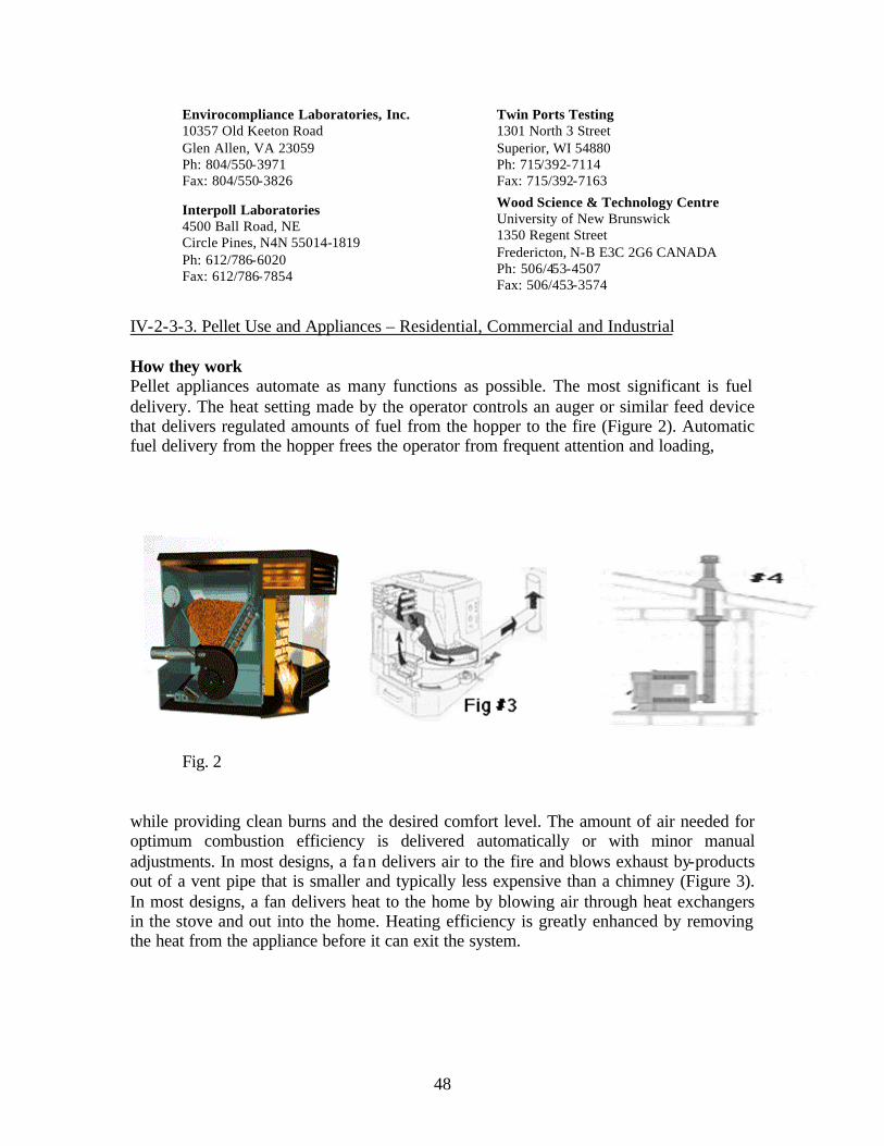
Envirocompliance Laboratories, Inc. Twin Ports Testing 10357 Old Keeton Road 1301 North 3 StreetGlen Allen, VA 23059 Superior, WI 54880Ph: 804/550-3971 Ph: 715/392-7114Fax: 804/550-3826 Fax: 715/392-7163
Interpoll Laboratories Wood Science & Technology Centre
4500 Ball Road, NE University of New Brunswick
Circle Pines, N4N 55014-1819 1350 Regent Street
Ph: 612/786-6020 Fredericton, N-B E3C 2G6 CANADA
Fax: 612/786-7854 Ph: 506/453-4507 Fax: 506/453-3574
IV-2-3-3. Pellet Use and Appliances – Residential, Commercial and Industrial
How they work Pellet appliances automate as many functions as possible. The most significant is fuel delivery. The heat setting made by the operator controls an auger or similar feed device that delivers regulated amounts of fuel from the hopper to the fire (Figure 2). Automatic fuel delivery from the hopper frees the operator from frequent attention and loading,
Fig. 2
while providing clean burns and the desired comfort level. The amount of air needed for optimum combustion efficiency is delivered automatically or with minor manual adjustments. In most designs, a fa n delivers air to the fire and blows exhaust by-products out of a vent pipe that is smaller and typically less expensive than a chimney (Figure 3). In most designs, a fan delivers heat to the home by blowing air through heat exchangers in the stove and out into the home. Heating efficiency is greatly enhanced by removing the heat from the appliance before it can exit the system.
48

Types of pellet appliances Pellet stoves come in a wide range of style, size, and finish that are capable of producing 10,000 to 500,000 Btu/hr. Freestanding pellet stoves (Figure 4) offer great flexibility in installation choices. Supported by a pedestal or legs, they are designed to be installed in almost any living area of the home (restrictions may apply to sleeping areas). Freestanding stoves are placed on a non-combustible floor protector. They are installed a specified distance from combustible surfaces that is usually smaller than that required for comparable cordwood appliances. Fireplace inserts (Figure 5) are installed in existing, working fireplaces. A decorative panel covers the space between the insert and the fireplace opening. Some pellet inserts are approved only for use in masonry fireplaces, while others can also be installed in approved factory-built metal fireplaces. Built- in appliances (Figure 6) are an economical choice that offers homes without an existing fireplace the look of an insert in a fireplace setting. A unit tested and listed as a built in can be boxed in with close clearances to combustible framing. Noncombustible materials like brick can be applied to the area around the front of the unit to give the appearance of a fireplace. A noncombustible floor protector is required, sometimes with spacers to provide an air space under the unit. Pellet furnaces are large units designed to heat an entire house through duct work. They are usually installed in a basement or other nonliving area of the house. Like pellet stoves, furnaces require venting to the outside.
Pellet stoves are also categorized according to their method of delivering fuel. Top feed stoves deliver pellets from a tube or chute above the fire, and bottom feed stoves deliver pellets from behind or beside the burn pot directly to the fire (see Figure 2). There are many variations within these categories, but in general, bottom feed stoves tend to perform better with the wider range of ash content in standard grade fuel because the feeding action moves ash and clinkers away from the burn area. This action helps keep air inlets open and thereby reduces the frequency of cleaning the burn pot. Top feed stoves may have some advantage in overall heating efficiency since pellets remain in the burn pot until they are completely burned, and exhaust gases tend to move slower, allowing improved heat trans fer. Special grates or rotating burn pots in some top feed designs can also move ash and clinkers from the air inlets to reduce maintenance frequency. If only standard grade pellets are available, or if there is a desire to burn a higher ash or special fue l like corn or nut hulls, special attention must be paid to the issue of fuel delivery, ash content, and stove compatibility. Otherwise, design differences are less significant considerations of relative degrees of efficiency and maintenance frequency. This technology is also valuable for non-residential buildings such as municipal buildings hotels, resorts, restaurants, retail stores, offices, hospitals, and schools.
How to select size of unit The wide range of heat output possible with pellet stoves reduces the number of different stove sizes needed for most heating situations. Within the range of pellet stove sizes, choices involve input from different sources. Information from manufacturers is of necessity general in nature given the many variables in climate, home construction, and personal comfort. Btu output and efficiency ratings must be qualified to be useful. Overall efficiency, a measurement of the percentage of the energy available in a fuel that
49

is actually delivered as heat in the home, is more important than combustion efficiency, a measurement of the percentage of available energy that is converted to heat (some of which escapes through the vent). A knowledgeable dealer is the best source of information about sizing. You can help the dealer by providing information about factors that affect stove sizing:
• your intended purpose; primary or backup heat source for the entire house or a selected area
• house size and layout; sketch with room and house size estimate or building plans very helpful
• heating characteristics of your home; insulation and tightness of construction • your idea of comfort; day and night.
Appliance features Stove size, type, and appearance generally begin the process of appliance selection. The choice may then include considerations of performance, convenience, and cost. Operational convenience is affected by a number of design features. Hopper capacity, which ranges from under 40 to over 100 pounds, plays a role in loading frequency. Hopper size should match heating needs on a reasonable loading cycle, typically once daily. The means of adjusting controls affect convenience also. Manually controlled stoves require occasional adjustment of air inlet dampers as the fuel feed rate is changed. Stoves with more sophisticated controls are able to monitor burn conditions and make these adjustments automatically. The choice may focus on the lower cost of manual stoves versus the value of minimal interaction with stove operation. Some owners prefer the reduced attention of automatic air controls while others enjoy more active participation in tending the fire. Features which affect ash tolerance and fuel compatibility may influence both performance and convenience, particularly in regions where fuel grade choice is limited.
50
While many newer stoves perform well with increasingly wider ranges of fuel, some designs are better at extending good performance with longer intervals between routine maintenance. Bottom fuel feeding moves ash and clinkers away from air inlets. Specially designed grates in top feed designs either allow heavier ash and clinkers to fall through to the ash drawer, or they rotate themselves to move ashes and keep air inlets open. In both stove designs, a larger ash drawer reduces ash removal frequency, and grates which can be dumped without stopping operation add convenience. As long as a compatible pellet fuel is available, the issue of ash tolerance is one of convenience, not the acceptability of stove design. Ease of maintenance is enhanced by features that make routine cleaning tasks easier. The heat exchanger can be cleaned by simply moving an external rod handle back and forth on some stoves. Other designs demand a more involved cleaning procedure. Ask the dealer to demonstrate heat exchanger cleaning as well as access to ash traps, receptacles behind the fire chamber designed to separate fly ash from the exhaust. Although pellet stoves are safety tested as a solid fuel heater by an accredited laboratory, stoves safety tested to ASTM Standard E 1509 undergo stringent testing specifically designed for pellet appliances to assure their safety and performance reliability . Other features bring added convenience and enjoyment:
• Automatic ignition. Offers simple, reliable startup. Typically more desirous on stove used intermittently than on one used continuously.
• Remote thermostatic control. Controls heat output based on room temperature. Ensures even temperature from unattended stove regardless of changes in the weather. Discuss with the dealer the merits of thermostats and stove startup design: automatic ignition stoves cycle on and off according to heat demand; manual start stoves keep fire at low setting and return to high.
• Large glass view and air wash system. Offers fire viewing, particularly enjoyable in living area installations. Air wash keeps glass clean by directing warm air over the glass during combustion.
• Imitation log sets (stove manufacturer approved only). Improve aesthetics of the fire. May increase frequency and difficulty of maintenance; ask if removable.
• Blower quietness. A concern in some areas of the house, depending on room use and personal preference.
• Backup power source. Consideration for primary heat stoves in areas subject to frequent power outages. Should automatically switch from utility power to battery and back again.
• Extended warranty for components. Low cost, high value extension of warranty on components (from normal one or two years to as many as five).
About pellet stove dealers
Pellet stoves are not difficult to operate or maintain with a little initial instruction. You may want to ask what owner training materials and services are available before you buy. Support after the sale adds value to the purchase price. Many dealers offer training through stove operation demonstration, "Stove School" classes, newsletters, or by telephone in addition to the instructional manuals and videos provided by manufacturers.
51

Just as with automobiles and other mechanical products, most owners will need professional service. Dealers can provide details of warranty service, including extended warranty plans, as well as regular (usually annual) service. Dealers will discuss a fuel plan with you, detailing what locally available fuels are compatible with your stove and what sources supply them. Most dealers are glad to demonstrate their qualifications by supplying satisfied customer references. Some dealers have taken a nationally administered exam to become certified by the HEARTH Education Foundation.
Shopper's Checklist • Fuel requirements and availability • Ease and expected frequency of routine owner maintenance • Availability and cost of professional service • Dealer's owner training program and materials • Special features like self- igniter system, remote thermostatic control, glass air
wash and imitation logs for fire viewing, ash drawer size • Understanding of heating system requirements and installation plan • Backup power or alternate heat source plan (if important) • Warranty details • Total system and installation cost
Installation, Venting, Maintenance and Use
As you choose the appliance, you will be asked to provide information and make decisions about installation details. Professional guidance in these matters is both helpful in choosing the optimum system for your needs and essential to proper performance and safety. Knowing installation basics can help you communicate your preferences and understand professional recommendations. Note: The following information was prepared by HEARTH Education Foundation, in cooperation with the Hearth Products Association and the Pellet Fuel Institute.
Placement
What factors determine appliance location? For maximum enjoyment and heating effectiveness, a major living area where the family spends leisure hours and which provides heat flow to other areas is usually a strongly preferred location for the stove. The pellet heating professional considers the factors that determine whether installation requirements can be met in the homeowner's preferred location:
• Venting. May be limited by factors like obstructions above vertical venting through the ceiling and roof or by the distance to an outside wall for horizontal venting.
• Outside air for combustion, if needed. Must be drawn from an approved location.
52
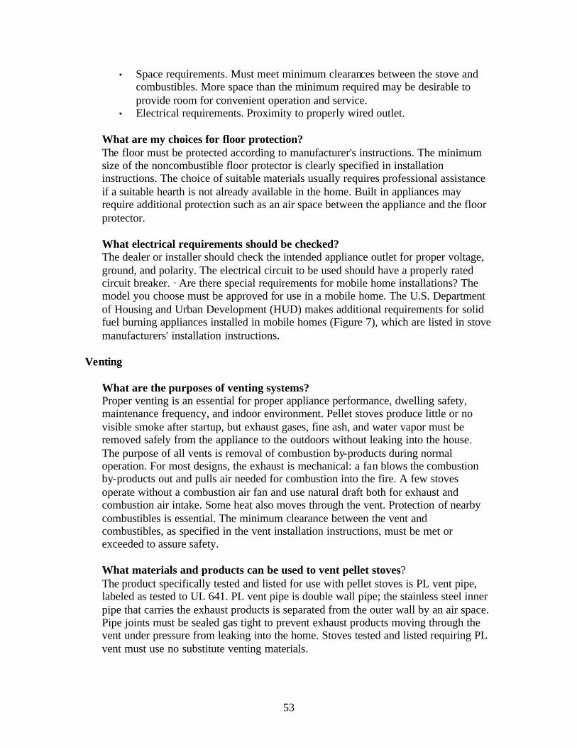
• Space requirements. Must meet minimum clearances between the stove and combustibles. More space than the minimum required may be desirable to provide room for convenient operation and service.
• Electrical requirements. Proximity to properly wired outlet.
What are my choices for floor protection? The floor must be protected according to manufacturer's instructions. The minimum size of the noncombustible floor protector is clearly specified in installation instructions. The choice of suitable materials usually requires professional assistance if a suitable hearth is not already available in the home. Built in appliances may require additional protection such as an air space between the appliance and the floor protector.
What electrical requirements should be checked? The dealer or installer should check the intended appliance outlet for proper voltage, ground, and polarity. The electrical circuit to be used should have a properly rated circuit breaker. · Are there special requirements for mobile home installations? The model you choose must be approved for use in a mobile home. The U.S. Department of Housing and Urban Development (HUD) makes additional requirements for solid fuel burning appliances installed in mobile homes (Figure 7), which are listed in stove manufacturers' installation instructions.
Venting
What are the purposes of venting systems? Proper venting is an essential for proper appliance performance, dwelling safety, maintenance frequency, and indoor environment. Pellet stoves produce little or no visible smoke after startup, but exhaust gases, fine ash, and water vapor must be removed safely from the appliance to the outdoors without leaking into the house. The purpose of all vents is removal of combustion by-products during normal operation. For most designs, the exhaust is mechanical: a fan blows the combustion by-products out and pulls air needed for combustion into the fire. A few stoves operate without a combustion air fan and use natural draft both for exhaust and combustion air intake. Some heat also moves through the vent. Protection of nearby combustibles is essential. The minimum clearance between the vent and combustibles, as specified in the vent installation instructions, must be met or exceeded to assure safety.
What materials and products can be used to vent pellet stoves?The product specifically tested and listed for use with pellet stoves is PL vent pipe, labeled as tested to UL 641. PL vent pipe is double wall pipe; the stainless steel inner pipe that carries the exhaust products is separated from the outer wall by an air space. Pipe joints must be sealed gas tight to prevent exhaust products moving through the vent under pressure from leaking into the home. Stoves tested and listed requiring PL vent must use no substitute venting materials.
53

Venting materials and products that must not be used to vent pellet appliances include:
• Dryer vent • Gas appliance (Type B) vent • PVC (plastic) pipe • Single wall stove pipe (unless clearly approved by the installation manual and
local codes)
Pellet fireplace inserts and freestanding stoves are often vented into existing masonry and factory-built fireplace and woodstove chimneys (Figure 8). The chimney- should be inspected before installation to ensure that it is clean, mechanically sound, and meets local safety code requirements. The appliance manufacturer's installation instructions may require relining the chimney with an approved metal liner, pipe, or PL vent. Vents or grilles on the face of factory-built fireplaces which provide cooling air to the outside jacket of the fireplace must not be blocked. Cleanout access for future maintenance should be considered.
Venting layout options Mechanical Exhaust:
• Sidewall horizontal venting (Figure 9). Invariably the least expensive venting system. Disadvantage of potential smoke spilling into the house in the event of a power outage or component failure, or house depressurization (see discussion of next question).
• Horizontal vent with backup vertical venting (see Figure 10). Preferred horizontal method that avoids venting problems associated with unexpected appliance shutdown.
54

• Vertical venting through the ceiling and roof (Figure 11). Has the advantage of keeping vent gases warm and of providing natural draft to prevent problems in an unexpected shutdown.
• Venting into existing chimney (see Figure 8). Stove manufacturers provide recommendations for venting into masonry and factory-built chimneys, which may include partial or full chimney relining.
• Natural Draft: All vents for appliances designed without mechanical exhaust fans must meet stove manufacturer's requirements for minimum draft and must terminate above the roof.
Vertical (Figure 12) extends up from the stove and penetrates the ceiling and roof. Horizontal and vertical (Figure 13). Extends from the top or back of the appliance, penetrates the wall, turns up to penetrate the eave and roof. · Venting into existing chimney (see Figure 8). Follow manufacturer's recommendations for venting into masonr y and factory-built chimneys, which may include partial or full chimney relining.
Besides appliance requirements, what other factors may be considered in specifying pellet venting systems?
The following factors may play a role in the designation of the venting system:
• Altitude: High altitude installations, generally higher than 2500 feet above sea level, may require special venting options to provide adequate combustion air and/or draft.
• House Pressure: Extremely tight house construction or strong kitchen, bath, or other exhaust fans may create a negative pressure within the home that decreases venting effectiveness. May necessitate an approved outside air source.
• Windy Conditions. Unpredictable effects of high winds or prevailing wind conditions may necessitate the addition of vertical venting extending above the roof and/or special termination caps.
• Cleanout and Maintenance: The venting system must be designed with normal maintenance in mind.
How should pellet venting components be assembled and joined together? Appliance manufacturer's instructions should be followed closely regarding sealing joints and seams, particularly of pressurized mechanical exhaust vents. It is imperative that they be gas tight so that they cannot leak. Proper application of an approved sealant or sealing
55

band is typically required. Appliance manufacturer's instructions for pipe sealing which exceed vent manufacturer's instructions must take precedence. You can get a sense of what heating with pellets involves through an introduction to the principles of operation and the reasons for maintenance that you will come to understand as an experienced operator.
Operation
What's a good starting point for learning to operate a pellet stove? The rule here is "Before all else fails, read the instructions." Operating a pellet" stove is not difficult, but it is a new technology that calls for basic knowledge. Training videos accompany some stoves, and hands on demonstrations by many dealers and installers.
How do I start a fire? Small dry fue l (pellets) and combustion air provided by a fan on most designs make startup easy. Operating instructions provided with the stove give the specific steps to follow. Manual ignition stoves call for the owner to apply an approved gel or solid starter material (no liquids), light the pellets, and monitor the fire to see that the fire catches and the flame gradually grows. On automatic ignition stoves, pushing the start button feeds pellets to the burn pot and heats the self- igniter device.
What if the stove doesn't start properly? A safety device monitors startup and stops fuel feed if operating temperatures are not reached within a specified time period. If startup fails, the operator makes sure that the hopper has fuel, that fuel is feeding, and restarts the stove. Repeated failed lighting cycles indicate the need for maintenance or professional service.
What do I do after the stove starts? After control panel or air inlet adjustments and a quick performance check, the stove is set to provide hours of even, comfortable heat. Stoves equipped with a remote wall thermostat respond to owner setting and room air temperature by cycling on and off or by cycling from a low to high burn, depending on stove startup design.
What are signs of performance problems? Properly operated and maintained pellet stoves experience few, if any problems. Most of pellet stove operation is automatic, but sometimes combustion air adjustment is needed. A lazy, orange, sooty flame or dark smoke coming out of the vent (after startup and before shutdown) may indicate the need for more air. An overactive, "blow torch" flame calls for less air." Performance problems are more likely to be caused by neglected maintenance than by operation. Lazy flame, dark smoke, unusual sooting of glass, unexplained smoke spillage, and reduced heat output all point to the need for maintenance of appliance components and/or the venting system or for remedies for house depressurization. Problems related to mechanical failures usually result in safety switches shutting the appliance down. Appliance shutdowns may, however, indicate nothing more than owner forgetfulness (empty hopper) or hurry (improper startup), or
56

intermittent power failure. Unexplained, repeated appliance shutdowns call for professional advice and service.
How do I shut the stove down? Shutting the stove down is typically a matter of simply setting the control to the Off position according to operating instructions. The fuel feed stops delivering fuel right away, and after the stove cools sufficiently, all motors and blowers cease operation. The stove should NOT be shut down by unplugging the power cord.
What happens in an unexpected shutdown such as a power outage or component failure? Although fuel feed stops in a power outage, the pellets in the burn pot may continue to burn or smolder. The duration of this condition can vary with appliance design from a few minutes to an hour or more. The resulting smoke and hot gases rise, seeking the path of least resistance. If the exhaust vent does not have vertical sections to provide natural draft, smoke may spill into the home (Figure 14).
Maintenance
What are the routine things that I do to keep my stove working right? Routine maintenance tasks are essential to peak stove performance:
• Burn pot (Figure 15). Checked daily and cleaned periodically to keep air inlets open. Frequency of cleaning depends on fuel type, grade, and content.
• Ash drawer (see Figure 15). Emptying recommended before starting new fires and occasionally by interrupting stove operation. Frequency depends on fuel and stove design. Typically once or twice a week, but monthly in some new designs.
• Heat exchanger (Figure 16) On some stoves, simply a matter of moving a rod that scrapes the tubes inside the stove. May require professional service on others.
• Ash traps. Chambers located behind the fire chamber which prevent excess fly ash in the exhaust from exiting the stove. Easily accessed for ash removal by owners in some designs; on others requires professional service.
• Glass. Cleaned with glass cleaner when the glass is completely cool on stoves with effective air wash systems. May require more vigorous methods on others.
• Hopper. Checked for accumulated sawdust materials (fines). Fuel in the hopper and auger tube should be run out occasionally to prevent auger blockage by fines.
57

What are some of the more advanced maintenance tasks? Cleaning the venting system is usually performed by professionals (see below), but can be tackled by the handy stove owner with thorough knowledge and the right equipment. Motors and fans need occasional cleaning and may require lubrication. The wrong lubricant or wrong amount of lubricant can damage components. Some components which call for removal for service require replacement of a gasket . Gaskets for the fire chamber door, ash pan door, and hopper lid (on some designs) may need occasional replacement to assure a tight seal.
What professional maintenance and repair services will I need? Most pellet stove owners depend on professional service for cleaning and preventive maintenance on at least an annual basis. Many dealers offer service plans that offer reduced costs and convenient scheduling. Cleaning and maintenance services usually performed include:
• Emptying ash traps and cleaning exhaust passages behind the fire chamber. • Cleaning and lubricating fans and motors. • Cleaning the hopper and fuel feed system. • Cleaning the heat exchanger system. • Cleaning exhaust pipes and resealing the venting system if needed. • Verifying and adjusting the stove settings with proper gauges and meters. • Mechanical and electric components may eventually wear out and need repair or
replacement.
Many manufacturers now offer low cost, high value extended warranty on electrical components. You can also benefit from professio nal advice that helps you improve stove performance and convenience with operating tips or advice on fuel.
IV-2-4. Pellet Fuel Economics
A. Fuel Comparisons – Energy and Cost
Energy equivalencies and conversion factors:
1 Million Btu (1 MBtu) = 293 kW = 29.9 Boiler Hp = 1,000 lb Steam = 120 lb dry wood = 7 gal. Diesel Oil = 1000 cu.ft. (10 Therms) Natural Gas
Heating with wood can have economic benefits. Consider the comparisons in heating value. As a rule of thumb, a two-ton cord of hard wood yields about the same usable heat as 200 gallons of heating oil, a ton of hard coal, or about 4000 kilowatts of electricity. By comparing the cost of whichever fuel one uses with wood, you can figure the savings obtained by wood-burning. For example, 200 gallons of No. 2 fuel oil at $1.00/gallon costs $200.00. The same usable heat from wood would run $100 (1 cord of wood), a saving of $100! Of course, if you cut your own wood the savings can be even greater.
58

Pellets vs. Cordwood Comparison
Basis of comparison: 1. Wood contains approximately 8500 BTU per pound depending upon wood species and moisture content. 2. Wood (seasoned) has approximately 20% moisture while pellets have approximately 8% moisture.
Therefore:
2000 Lbs of Pellets at 8500 BTU per pound is 17,000,000 BTU per ton
Divide this figure by 80% (the efficiency of the pellet stove) to get 13,600,000 BTU per ton delivered to the home.
One cord of White Oak (oven dry) contains 29,000,000 BTU because the weight (oven dry) of this cord is 3500 lbs even though the heat content is the same per pound (8500 BTU/lb)as pellets. The BTU to home s with stoves of varying efficiency is as shown below.
80% efficient= 23,200,000 BTU into the home 70% ===20,300,000 BTU into the home 60% ===17,400,000 BTU into the home.
Therefore we can see that even in the worst case, a cord of oak is equal to 1 1/3 tons of pellets. In the best case, A cord of wood equals 1 3/4 ton of pellets.
Table IV-7 FUEL COST COMPARISON
FUEL PRICE COST PER MILLION BTUs OF USABLE HEAT
PREMIUM WOOD PELLETS per ton per MM BTUs
6% moisture $140.00 $10.67
8200 BTUs/LB. $150.00 $11.43 $160.00 $12.20
80% efficiency $170.00 $12.95
$180.00 $13.71 $190.00 $14.48
PROPANE per gallon per MM BTUs
90,000 BTUs/gallon $1.00 $13.88 $1.20 $16.66
80% efficiency $1.40 $19.43
59

ELECTRIC 3415 BTUs/kwh
95% efficiency
OIL #2
138,000 BTUs/gallon
80% efficiency
NATURAL GAS 100,000 BTUs/therm
80% efficiency
COAL
12,000 BTUs/lb.
75% efficiency
FIREWOOD
air dried 25% MOISTURE 20 MM BTUs 65% efficiency
$1.60 $22.21 $1.80 $24.98
$2.00 $27.76 per KWH per MM BTUs $0.06 $18.48
$0.08 $24.64 $0.10 $30.80 $0.12 $36.96
$0.14 $43.12 $0.16 $49.28 per gallon per MM BTUs
$0.80 $7.24 $1.00 $9.05 $1.20 $10.86
$1.40 $12.67 $1.60 $14.48 $1.80 $16.29
per MCF per MM BTUs $.60 $7.50 $.80 $10.00
$1.00 $12.50 $1.20 $15.00 $1.40 $17.50
$1.60 $20.00 per ton per MM BTUs $120.00 $6.66
$140.00 $7.77 $160.00 $8.88 $180.00 $9.99
$200.00 $11.11 $220.00 $12.27 per cord per MM BTUs
$90.00 $6.92 $110.00 $8.46 $130.00 $10.00
$150.00 $11.53 $170.00 $13.08 $190.00 $14.61
Efficiency Rating is based on newer modern appliances. Older heating appliances may be far less efficient therefore increasing cost per MMBTU.
Pellet Cost
The selling price of pellets currently ranges anywhere from $120-200 per ton and averages $150. Price varies by region, availability, and season, just like other heating
60

fuels. Because bags of pellets stack and store easily, many prudent customers take advantage of lower off season prices and ensure their winter fuel supply by buying early.
Selling price, of course, is only a part of the cost picture. The primary issue is the cost of energy, which is measured in dollars per million British thermal units ($/MM Btu). Pellets purchased at the average $150 per ton and burned in a typical pellet stove cost about $11.50 per million Btu, a figure that is less than the cost of electric heat and competitive with average energy costs of some other fuels (see fuel cost chart, put in table, for comparisons at other prices). While tables and charts assume average appliance efficiencies and fuel costs, real world experiences vary widely. The actual cost of heating a home must take into account the insulation and tightness of the home, its size and layout, the level of comfort desired, and local climate. Other economic factors impacting energy costs, though hard to quantify, are also worth consideration. Biomass pellets are a renewable source of energy which reduce the use of dwindling fossil fuels with their greenhouse gas emissions, often imported from foreign countries. Every ton of waste material used in pellets reduces the rising costs associated with waste disposal.
Made from sawdust and wood chips waste materials from furniture making and other wood manufacturing processes, pellets are simply trees saved from the landfill. At an average price of $150 a ton, a $450 yearly investment in pellets will heat the average North American home. This places pellet heat, on a value-per-dollar scale, just slightly behind black gold (given current oil prices), substantially ahead of electric heat and increasingly on par with natural gas. Moreover, pellet fuel has not ridden the wave of market fluctuation the way oil and natural gas have. In 1990, a 40-pound bag of pellets cost $3, and we found the same price today at retail stores. Typically, pellet costs have not even kept pace with inflation, which actually means that your $3 bag is a much better buy now than it was ten years ago.
The cost of pellet fuel may depend on the geographic region where it is sold, and the current season. It costs about the same as cord wood and less than some other fuels. ((Pellet fuel is estimated to be only about one-third the cost of electricity.)) That could mean a large savings over the years.
A pellet cost study estimate has been performed to determine the economic feasibility of pellet manufacturing plant on the Umatilla Indian Reservation. The results are summarized in Table IV-8 below. Three different cases were examined with Case A being the base case while Case B and C examine the effect of inflating the base case assumptions by 10% and 20% respectively. The base case is for a plant that receives virgin and recyclable wood at a delivered cost of $20/ton and turns it into commercial grade bagged pellet fuel at a rate of 3tons/hr (6,000 ton/yr) that sells for $100/ton f.o.b. The base case shows a 20% after taxes annual return on investment. The base case annual revenues are $600,000 and production cost of $ 428,537 ($71.42/ton).
61

Table IV-8. Wood Pellet Manufacturing Cost Estimate
(3 ton/hr, 6,000 ton/yr capacity)
Case A Case B Case C dollars, $ dollars, $ dollars, $
Fixed Capital Costs buildings (2) 116,000 127,600 140,360 chipper 125,000 137,500 151,250 hammer mill 50,000 55,000 60,500 pellet mill 250,000 275,000 302,500 sizing 25,000 27,500 30,250 bagging 40,000 44,000 48,400
subtotal 606,000 666,600 733,260
Direct Manuf. Costs feedstock 120,000 132,000 145,200 utilities 60,600 66,660 73,326 labor, admin., mgt. 145,000 159,500 175,450 maintenance & repair 18,180 19,998 21,998 supplies 2,727 3,000 3,300 laboratory charges 9,000 9,900 10,890
subtotal 355,507 391,058 430,163
Indirect Manuf. Costs overhead 58,000 63,800 70,180 local taxes 0 0 0 insurance 3,030 3,333 3,666 depreciation 54,800 60,280 66,308
subtotal 61,030 67,133 73,846
General Expenses R&D 6,000 6,600 7,260 advertising & sales 6,000 6,600 7,260
subtotal 12,000 13,200 14,520
Total Production Cost 428,537 471,391 518,530 Revenues 600,000 600,000 600,000 Net annual profit 171,463 128,609 81,470 Income taxes, 50% NP 85,732 64,305 40,735 Net profit after tax 85,732 64,305 40,735 Annual Rate of Return 20.0% 13.6% 7.9%
B. The Pellet Fuel Industry
Pellet mills across the country receive, sort, grind, dry, compress, and bag wood and other biomass waste products into a conveniently handled fuel (Figure 1). Today, over sixty pellet mills across North America produce in excess of 610,000 tons of fuel per year, a figure that has more than doubled in the last five years. Pellets are available for purchase at stove dealers, nurseries, building supply stores, feed and garden supply stores,
62
and some discount merchandisers. Pellets are usually packaged in forty pound bags and sold by the bag or by the ton (fifty bags on a shipping pallet). Some mills offer twenty pound bags for easier handling.
C. Marketing Factors
Countries introducing renewable fuel initiatives include Great Britain, Ireland, South Africa, Scandinavia, U.S.A., Canada.
California (USA) is dedicating a little less than 1 percent of every electric bill to supporting research as well as programs for green power; the fund is expected total about $540 million by 2002.
Nearly all the 600,000 pellet stoves operating in North America require current to run the heat fans and pellet feeders. This would represent only a conditional annoyance were it not for the fact that just over 50% of pellet stove owners use the appliance as their primary source of heat. Throw in an ice storm of the kind that left huge portions of Vermont, New Hampshire and southeastern Canada without power last winter and you have invited a potentially home-abandoning situation. As a result, the pellet stove industry has not seen anything like the robust, Y2K-fear-driven conventional woodstove sales. "Eighty percent of the people who look at a pellet stove are worried about its grid dependency," reports Mark Drisdelle of Dell Point Technologies Inc., a pellet stove manufacturer out of Montreal, Canada. "They are more than a little hesitant to make a $2,000 investment in a primary source of heat if it isn't flexible enough to function without the grid if necessary."
Advantages of pellets
The first appeal of pellets is their convenience. Bags of pellets stack compactly and store easily. A ton of pellets can be stacked in an area as small as four feet wide, long, and high, an area about half the space needed for a cord of wood. Pellets are also convenient because they load easily and cleanly into the stove hopper. Loading the hopper is normally required only once a day and may be even less frequent when the stove is used on low settings. The small size of pellets allows for precisely regulated fuel feed. In turn, combustion air can be regulated easily for optimum burn efficiency since the amount of fuel in the burn pot is predictable and consistent. High combustion efficiency is also due to the uniformly low moisture content of pellets (consistently below 10% compared to 20 to 60% moisture content in cordwood). Uniformly low moisture, controlled fuel batches, and precisely regulated combustion air means high heat output and a low level of unwanted emissions. Other environmental benefits besides clean burns result from the use of pellet fuels. As a biomass fuel, pellets offer the advantages of sustainable energy supplies through renewable raw materials. In addition, pellets are a by-product, not a primary user, of these renewable materials. Using pellets also helps reduce the costs and problems of waste disposal. In 1993-94, more than 6.5 million cubic yards of waste were diverted from landfills and converted to home heating in the form of pellets. As part of
63

the tradition of the hearth, pellet burning offers the enjoyment of fire viewing and active participation in providing winter comfort in the home.
IV-2-4. Regulatory and Environmental Issues
Pellet appliances are subject to the EPA emission standards for new wood burning stoves. New stoves must be certified by the manufacture as meeting these standards which is achieved by their participation in the EPA Stove certification program. In general the particulate level is extremely low because the moisture has been extracted, and the feed mechanism is regulated to ensure the correct fuel to air ratio.
IV-2-4-1Emissions
One way we can help address sustainability is to use a fuel from renewable sources. Renewable energy sources continue to play an increasingly important role in our future energy mix. Many countries have introduced renewable energy initiatives to reduce their dependence of fossil fuels which contributes to greenhouse gas emissions the major cause of global warming.
The term “renewable energy” refers to several energy sources which have little in common except they do not deplete existing resources. Renewable energy sources include biomass, hydro, solar, earth and waste energy.
Pellet fuel is classified as biomass and is one of the safest, cleanest ways to heat.
The U.S. Environmental Protection Agency is proposing tough new regulations for particulate matter. They estimate that lowering emissions to meet the proposed standards would save $8 to $14 mostly in health related costs, for every dollar spent on air pollution controls.
Pellet fuelled stoves offer the lowest particulate matter (pm) emissions of all solid fuels, 1.2 gm per hr. while a fireplace with wood has emissions of 47.gm per hr. The most energy efficient wood stove has emissions of 6 gm per hour.
64

Source: B.C Pellet Fuel Association
Emissions Comparisons
Acid Equivalents Emitted Carbon Monoxide Emissions per Quad of Heat Delivered
Particulate Matter (5G) Emmissions Greenhouse Gas Carbon Equivalent per Quad of Heat Delivered
Source: Pinnecale Pellet Inc.
IV-2-5. References
Oregon Department of Energy, 2003, “Biomass Resource Assessment and Utilization in Eastern Oregon.”
65

IV-3. Bio-Diesel Fuel
The solution to environmental degradation and energy crises is conservation and utilization of renewable forms of energy sources, for which biodiesel leads the pack.
IV-3-1 Conversion Process
Although straight vegetable oil can be used as fuel substitute for diesel engines, early biodiesel researchers discovered that such fuel was not especially good, unless the oil is heated or transformed such that its viscosity will be comparable to diesel fuel, or the engine is equipped with pre-combustion chamber. Faced with the prospect of having to modify millions of engines worldwide, researchers in the late 1970s and 1980s opted to modify the vegetable-oil fuel instead, hence, the transesterification process. Basically, transesterification is a chemical process that uses an alcohol and application of heat to react with the triglycerides contained in vegetable oil and animal fats to produce biodiesel (or alkyl esters) and glycerin (Cruz, 1992). Transesterification process was discovered in 1937, a Belgian patent was granted to G. Chavanne of the University of Brussels for the use of palm oil ethyl ester. The fuel was utilized in a commercial passenger bus operating between Brussels and Lovain (Knothe, 2001). Transesterification involves breaking every oil molecule (triglyceride) into three fatty acid chains and a separate glycerine molecule. Alcohol is added (e.g., me thanol, ethanol, isopropanol or butanol) during the process, so each of the fatty acid chains attaches to one of the new alcohol molecules. In theory, three alcohol molecules are needed per triglyceride molecule, as reflected in Figure IV-3-1 below.
66

TRADITIONAL TRANSESTERIFICATION H HEAT H
CH3+ CH3 CH3 +
CH3H CATALYST H
1 triglyceride + 3 alcohol = 3 esters + 1 glycerol
(R1, R2, & R3 represents the fatty acid hydrocarbons)
.
H-C-OOCR1 -OH CH3-OOCR1 H-C-OH H-C-OOCR2 -OH -OOCR2 H-C-OH H-C-OOCR3 -OH CH3-OOCR3 H-C-OH
Figure IV 3.1 . Transesterification Process to Produce Biodiesel
The production of biodiesel, or alkyl esters is a well known and practiced chemical reaction which has recently been reviewed by Ma and Hanna (1999). There are fo ur basic routes which are listed below along with the transesterification reaction.
• Base catalyzed transesterification of the oil with alcohol, • Direct acid catalyzed esterification of the oil with methanol • Conversion of the oil to fatty acids, and then to alkyl esters with acid
catalysis. • Enzymatic transesterification with lipase
Small-scale production using methanol and base catalyst (potassium hydroxide) has extensively used by homebrewers in the US, and in developing countries (e.g., Philippines, Bulga ria, India, Paraguay), as shown in Figure IV 3.2. Athough transesterification requires the addition of heat, the cruzesterification process has eliminated the addition of heat and mixing time is drastically reduced to 30 minutes reaction time, and fuel produced is not sweetened, just filtered (Cruz, 2001a; Cruz, 2001b; Cruz 2002, Santos, et al, 2002, Zamfirov, et al 2002; and Cruz, 2004).
67
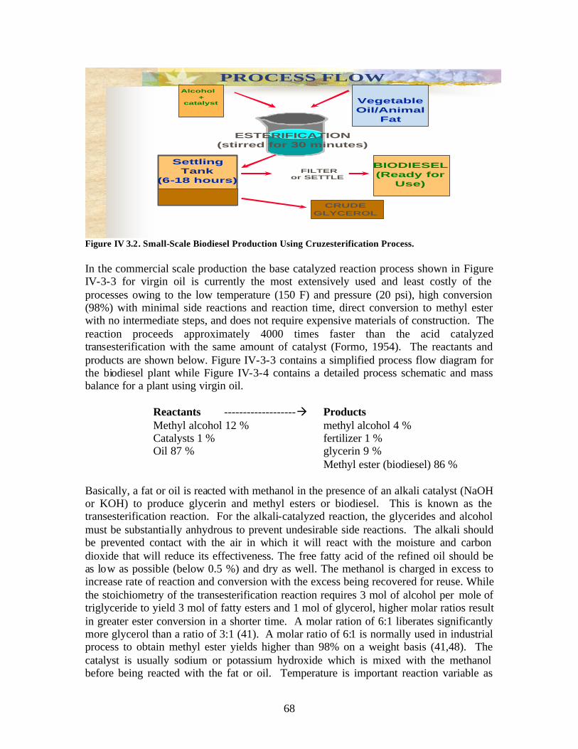
PROCESS FLOW Alcohol
+ catalyst Vegetable
Oil/Animal Fat
ESTERIFICATION (stirred for 30 minutes)
Settling Tank
BIODIESEL (Ready for
Use)
FILTER or SETTLE
CRUDE GLYCEROL
(6-18 hours)
Figure IV 3.2. Small-Scale Biodiesel Production Using Cruzesterification Process.
In the commercial scale production the base catalyzed reaction process shown in Figure IV-3-3 for virgin oil is currently the most extensively used and least costly of the processes owing to the low temperature (150 F) and pressure (20 psi), high conversion (98%) with minimal side reactions and reaction time, direct conversion to methyl ester with no intermediate steps, and does not require expensive materials of construction. The reaction proceeds approximately 4000 times faster than the acid catalyzed transesterification with the same amount of catalyst (Formo, 1954). The reactants and products are shown below. Figure IV-3-3 contains a simplified process flow diagram for the biodiesel plant while Figure IV-3-4 contains a detailed process schematic and mass balance for a plant using virgin oil.
Reactants -------------------� Products Methyl alcohol 12 % methyl alcohol 4 % Catalysts 1 % fertilizer 1 % Oil 87 % glycerin 9 %
Methyl ester (biodiesel) 86 %
Basically, a fat or oil is reacted with methanol in the presence of an alkali catalyst (NaOH or KOH) to produce glycerin and methyl esters or biodiesel. This is known as the transesterification reaction. For the alkali-catalyzed reaction, the glycerides and alcohol must be substantially anhydrous to prevent undesirable side reactions. The alkali should be prevented contact with the air in which it will react with the moisture and carbon dioxide that will reduce its effectiveness. The free fatty acid of the refined oil should be as lo w as possible (below 0.5 %) and dry as well. The methanol is charged in excess to increase rate of reaction and conversion with the excess being recovered for reuse. While the stoichiometry of the transesterification reaction requires 3 mol of alcohol per mole of triglyceride to yield 3 mol of fatty esters and 1 mol of glycerol, higher molar ratios result in greater ester conversion in a shorter time. A molar ration of 6:1 liberates significantly more glycerol than a ratio of 3:1 (41). A molar ratio of 6:1 is normally used in industrial process to obtain methyl ester yields higher than 98% on a weight basis (41,48). The catalyst is usually sodium or potassium hydroxide which is mixed with the methanol before being reacted with the fat or oil. Temperature is important reaction variable as
68

well. For the transesterification of refined soybean oil with methanol (6:1) using 1% NaOH, three different temperatures were used (Freedman et al., 1984). After 0.1 h, ester yields were 94, 87 and 64% for 60, 45 and 32°C, respectively. After 1 h, ester formation was identical for the 60 and 45°C runs and only slightly lower for the 32°C run.
In the case where used cooking oil is employed, pretreatment is required to deal with the free fatty acid (FFA) content in the oil if FFA exceeds 5%.. The pretreatment required consists of an esterifcation reactor, glycerin washing column and methanol distillation column. This adds complexity and cost over the process using virgin oil. Hence, a trade-off for using inexpensive used oil which has been investigated by Zhang et al. (2003).
The specifications for the biodiesel product are given in the Table IV.3.1 below. It should be apparent from these specifications that considerable laboratory support with accompanying expense is required to certify the biodiesel for retail sales.
Table IV.3.1. Biodiesel Specifications
Property ASTM Method Limits Units Flash point 93 100.0 min Degree C Water & sediment 2709 0.05 max Vol.% Carbon residue 4530 0.050 max Wt.% Sulfated ash 874 0.020 max Wt.% Kinematic viscosity@40C 445 1.9-6.0 mm2/sec sulfur 5453 0.05 max Wt. % cetane 613 40 min. Cloud point 2500 By customer Degree C Copper corrosion 130 No. 3 max. Acid number 664 0.80 max. mg KOH/g Free glycerin 6584 0.020 max. Wt. % Total glycerin 6584 0.240 max. Wt. %
69

Catalyst QualityPurification Methanol
Recovery ControlCatalyst Mixing
Methanol
Recycled Methanol
Vegetable Oil,Used Cooking Oil, Transesterification Animal Fats
Crude BioDiesel
Phase Re-Neutralization MethanolNeutralizing Neutralization Separation RecoveryAcid
Figure IV.3.43Commercial Biodiesel Process Schematic
Methyl Ester
Pharmaceutical Glycerin
Glycerin Purification
Crude Glycerin
70

Figure IV 3.4. Complex Commercial Biodiesel Process.Table IV 3.2. Alkali-catalyzed process to produce biodiesel from virgin oils
IV-3-1. Production
Vegetable oils including soy, rapeseed, mustard seed, canola and sunflower, make good biodiesel feedstock, as do animal fasts and used cooking oil from restaurants, known as
71

yellow grease. Yellow mustard, canola and rapeseed are crops particularly well adapted to the dry, sunny interior Northwest. Soybean oil accounts for about 75% of the U.S. crop oil production, with farmers producing about 15 billion pounds annually. Corn is the second- largest source of U.S. crop oil, with about 2 billion pounds of oil produced each year.
Biodiesel can be produced from a wide range of feedstocks: virgin vegetable oils, yellow/brown grease, used fryer oil, animal fats, fish oil and even pond algae. Listed in Table IV2.3 is information of oil yields from various agricultural products (Cruz, 2002).
Table IV.2.3 Oil Yields of Major Oilseeds Worldwide used in Biodiesel Production (Cruz, 2002). COMMON NAME LATIN NAME AVERAGE OIL YIELD
LBS/AC KG/HA LITERS/HA GALS/ACRE Palm oil Elais guineensis 4452 5000 5435 581 Coconut Cocos nucifera 2012 2260 2457 263 Jatropha Jatropha curcas 1416 1590 1728 185 Rapeseed, Industrial Brassica napus 890 1000 1087 116 Canola Brassica napus, B. rapa 579 650 707 76 Peanut Arachis hypogaea 792 890 967 103 Sunflower Helianthus annuus 712 800 870 93 Safflower Carthamus tinctorius 583 655 712 76 Soybean Glycine max 334 375 408 44 Hemp Caanavis sativa 272 305 332 35 Corn Zea mays 129 145 158 17 Cashew nut Anacardium occidentali 132 148 161 17 Oat Avena sativa 163 183 199 21 Palm Erythea salvadorensis 168 189 205 22 Lupine Lupinus albus 174 195 212 23 Rubber seed Hevea brasilienses 193 217 236 25 Kenaf Hibiscus cannabinus 205 230 250 27 Calendula Calendula officinales 228 256 278 30 Cotton Gossypum hirsutum 243 273 297 32 Coffee Coffea arabica 344 386 420 45 Linseed/Flaxseed Linum usitatissimum 846 950 1033 110 Hazelnut Coryllus avellana 361 405 440 47 Euphorbia Euphorbia lagascae 392 440 478 51 Pumpkin seed Cucubita pepo 400 449 488 52 Coriander Coriandrum sativum 401 450 489 52 Mustard Brassica alba 846 950 1033 110 Crambe Crambe abyssinica 524 589 640 68 Camelina Camelina sativa 436 490 533 57 Sesame Sesamum indicum 521 585 636 68 Gourd Cucurbita foetidissima 592 665 723 77 Rice Oriza sativa 620 696 757 81 Tung oiltree Aleurites fordii 703 790 859 92 Cocoa Theobroma cacao 768 863 938 100 Opium poppy Papaver somniferum 871 978 1063 114
72

Olive Olea europaea 907 1019 1108 118 Piassava Attalea funifera 990 1112 1209 129 Gopher plant Euphorbia lathyris 996 1119 1216 130 Castor bean Ricinus communis 1058 1188 1291 138 Bacuri Platonia insignis 1066 1197 1301 139 Pecan Carya illinoensis 1340 1505 1636 175 Jojoba Simondsia chinensis 1360 1528 1661 178 Babassu palm Orbignya martiana 1372 1541 1675 179 Macadamia nut Macadamia terniflora 1680 1887 2051 219 Brazil nut Bertholletia excelsa 1790 2010 2185 234 Avocado Persea americana 1974 2217 2410 258 Oiticia Licania rigada 2244 2520 2739 293 Buriti palm Mauritia flexuosa 2442 2743 2982 319 Pequi Caryocar brasiliense 2797 3142 3415 365 Macauba palm Acrocomia aculeata 3361 3775 4103 439
NOTES: 1. There are over 350 species of oleaginous crops (oil-bearing plants) with thousands of subspecies. 2. Many of the species/subspecies produce more in tropical climates and are harvested once a year. 3. Conversion used for oil density was 920 g/liter. 4. Biodiesel yield is estimated as the same as oil yield.
Although palm oil has the greatest oil yield (over 5,000 kg/hectare), worldwide use as biodiesel is only 1%. Rapeseed leads the pack at 84%, followed by sunflower at 13%, other oilseeds and soybean oil are also at 1% (Korbitz, 1999).
Vegetable oils including soy, rapeseed, mustard seed, canola and sunflower, make good biodiesel feedstock, as do animal fats and used cooking oil from restaurants, known as yellow grease. Yellow mustard, canola and rapeseed are crops particularly well adapted to the dry, sunny interior Northwest. The chemical properties of some vegetable oils are shown in Table IV-3-4.
Table IV.3.4. Chemical Properties of Selected North American Oilseeds.
Soybean oil accounts for about 75% of the U.S. crop oil production, with farmers producing about 15 billion pounds annually. Corn is the second- largest source of U.S. crop oil, with about 2 billion pounds of oil produced each year.
73

IV-3-2. Biodiesel Economics
There are two aspects of the cost of biodiesel, the costs of raw material (fats and oils) and the cost of processing. The cost of raw materials accounts for 60 to 75% of the total cost of biodiesel fuel (Krawczyk, 1996). The use of used cooking oil can lower the cost significantly. However, the quality of used cooking oils can be bad (Murayama, 1994). Studies are needed to find a cheaper way to utilize used cooking oils to make biodiesel fuel. Kreutzer (1984) has pointed out several choices, first removing free fatty acids from used cooking oil before transesterification, using acid catalyzed transesterification, or using high pressure and temperature
It has been pointed out (NREL, 1998; HySEE, 1995) that biodiesel made from rapeseed oil is very expensive, due mostly to the high cost of rapeseed oil. Rapeseed oil is a commodity and has higher valued uses than biodiesel; therefore, its price is largely set by those other markets. This makes it difficult to make biodiesel from rapeseed oil for less than $3.00/gal. However, the basis of NREL’s assumptions for feedstock is refined virgin oil from edible rapeseed (more popularly known as canola), and possible income from meal after extracting the oil from the oilseed and crude glycerin are excluded (Cruz 2001; Cruz, 2002; Santos, et al, 2002; and Zamfirov, et al, 2002). It should be pointed out that process-wise, extraction of oil from soybean is the most expensive. Because of massive subsidies in the US, cost of soybean oil has been made artificially low, an examp le of which is introduced through USDA’s Commodity Credit Corporation’s U.S. Bioenergy Program in late 2004, and the original visions of the National Biodiesel Board (Pahl, 2005). It should be also noted that worldwide use of rapeseed oil as biodiesel feedstock is 84%, while soybean is only 1% (Korbitz, 1999).
Several economic feasibility scenarios have been presented (NREL, 1998) to deal with the high cost of virgin oil feedstock.
• Technology options are currently available to effectively process biodiesel with free fatty acids up to 5%.
• Although technology to handle 10%-15% levels of free fatty acids in the feedstock are available, they are fewer in number and need additional optimization. Furthermore, the technologies to process 10%-15% levels of free fatty acid are not commercially available.
• Most used restaurant grease is below 15% free fatty acid, and with technology to process them, these materials are now viable feedstocks for biodiesel production.
• Beef tallows and waste frying oils are less expensive than soybean oil, and could represent an effective option to reduce the cost of biodiesel as well as extending the supply of biodiesel.
An NREL (1998) report providing an empirical overview reflects the volatility of market prices for crop and waste oils as well as petroleum diesel. The total U.S. supply of crop and waste oil, about 28 billion gallons, is only a fraction of the U.S. annual demand for transportation diesel fuel. Furthermore, the price of diesel fuel (about $.60/gal) is much lower than crop oil prices, which range from $1.73/gal to $4.85/gal. The market price for
74

animal fats and waste grease ranges between $1.19/gal to $1.29/gal, which is less than the price of crop oils but still significantly higher than petroleum diesel. Given the prevailing market prices for these feedstocks, their use for biodiesel will be limited to niche markets where premium prices are paid for fuels with preferred environmental qualities. Table IV-3-5 below gives Wall Street Journal commodity quantity prices for March 1, 2005.
Table IV.3.5. Commodity Prices Commodity Price, 3/1/05 Price, 3/1/04 Soy bean oil, FOB IL $ 0.2304/lb $ 0.3569/lb Tallow, FOB Chicago $ 0.165/lb $ 0.16/lb Lard, Chicago $ 0.175/lb $ 0.252/lb Grease, Chicago $ 0.152/lb $ 0.142/lb Diesel, 0.05S, NY harbour $ 1.496/gal $ 0.9917/gal
The results of a number of economic evaluations for production are shown in the Table IV-3-6 below.
Table IV.3.6 . Economic evaluations for biodiesel production plants
At present, the high cost of biodiesel is the major obstacle to its commercialization. Biodiesel usually costs over US$0.5/l, compared to US$0.35/l for petroleum based diesel (Y. Zhang, et. al., 2003). It is reported that the high cost of biodiesel is mainly due to the cost of virgin vegetable oil (Krawczyk, 1996; Connemann and Fischer, 1998). For example, in the United States, soybean oil was sold on average for $0.36/l in June 2002 (Chemical Market Reporter, 2002). Therefore, it is not surprising that biodiesel produced from pure soybean oil costs much more than petroleum-based diesel. The use of waste cooking oil instead of virgin oil to produce biodiesel is an effective way to reduce the raw material cost because it is estimated to be about half the price of virgin oil (Supple et al., 1999). In addition, using waste cooking oil could also help to solve the problem of waste oil disposal (Wiltsee, 1998).
75
However, biodiesel production at small-scale or village- level was very competitive based on actual production experience by Cruz (2004) over a 15 year period of biodiesel production through the “cruzesterification” process in the US and countries like the Philippines, Bulgaria, and India. Because no heat was added during the processs, biodiesel was unwashed but filtered, and the worth of crude glycerin was included, biodiesel was produced at less than $2.00 per gallon using tropical oilseeds (coconut, palm oil, physic nut, etc). Biodiesel using used cooking/frying oil was less than $1.00 per gallon when the oil was free, and less than $2.00 per gallon when the yellow grease was bought from oil recyclers (Cruz, 2002; Santos, et al, 2002; and Zamfirov, et al, 2002).
Zhang et. al., (2003) have performed a detailed analysis of the technological and economic aspects of biodiesel from virgin and used cooking oils. The analyis was based on a biodiesel production rate of 8000 tonnes/yr. Four flowsheets for continuous alkali-and acid-catalyzed processes using virgin vegetable oil or waste cooking oil as the raw material were designed and simulated. The process flowsheet for the base catalyzed case for neat cooking oil is shown in Figure. All four processes proved to be feasible for producing a high quality biodiesel product and a top-grade glycerin by-product under reasonable operating conditions. However, each process had its limitations. The alkali-catalyzed process using virgin oil was the simplest with the least amount of process equipment but had a higher raw material cost than other processes. Despite the reduced raw material cost in us ing waste cooking oil, it was the most complex process with the greatest number of equipment pieces because of the addition of a pretreatment unit for free fatty acids removal. The acid catalyzed process using waste cooking oil had less equipment pieces than process the base catalyzed process, but the large methanol requirement resulted in more and larger transesterification reactors, as well as a larger methanol distillation column. Methanol distillation was carried out immediately following transesterifcation to reduce the load in downstream units in the process but more pieces of equipment made from stainless steel material were necessary than in the base catalyzed processes. The acid-catalyzed process with used cooking oil had the same merits and limitations as process that for virgin cooking oil. However, the addition of hexane and methanol/water solvents increased the number of process equipment pieces and sizes of some separation units in the process. In brief, for process simplicity, the alkali-catalyzed process using virgin vegetable oil was recommended over the others. However, if raw material cost is of concern, the acid-catalyzed process using waste cooking oil is a relatively simple process and proved to be a competitive alternative to the base catalyzed processes.
Zhang et al. (2003) economic study results are shown in Table IV.3.7 and IV.3.8 below where Process I and II are for base catalyzed process using virgin and used cooking oil while Processes III and IV are for acid catalyzed process using virgin and used cooking oil.
76

Table IV. 3.7 Economic Study Using Case 1.
Case 1 assumes 85 wt.% glycerin
77

Table IV.3.8 Economic Considerations for Case 1
Case 1 assumes 85 wt.% glycerin
On the basis of the economic assessment of four continuous alkali- and acid-catalyzed processes using virgin oil or waste cooking oil as the raw material, the following conclusions were made. The alkali-catalyzed process using virgin oil (process I) had the lowest total capital investment because of the relatively small sizes and carbon steel construction of most of the process equipment. For a plant producing 8000 tonne/year biodiesel, the total capital investment in process I was approximately half of that in the other processes. Process I thus requires the least initial investment when building a biodiesel plant. Raw material costs account for a major portion of the total manufacturing cost. Thus, reduction of the raw material cost should be the .rst step in optimizing the total manufacturing cost. Vir gin oil costs approximately 2–3 times more than waste cooking oil indicating that use of virgin oil leads to a substantial increase in total manufacturing cost. As a result, although process I had the lowest cost requirement for
78

building a biodiesel plant; it had a high manufacturing cost, off-setting any economic advantage in terms of return on investment or biodiesel break-even price.
When waste oil of low cost was used as the raw material, alkali-catalyzed process II required a pretreatment unit to reduce the content of free fatty acids. The cost associated with this pretreatment unit, including the cost for extra solvent, more than balanced the credit of using waste oil. This led to a reduced economic feasibility for process II. The acid-catalyzed system was insensitive to free fatty acids and no pretreatment unit was required. Accordingly, the acid-catalyzed processes to produce biodiesel from waste cooking oil (processes III and IV) had lower total manufacturing costs than the alkali-catalyzed process, so that the acid-catalyzed process would cost less to operate. Glycerine was a valuable by-product, which could add an appreciable credit to reduce the total manufacturing cost by approximately 10% for a plant with 8000 tonne/year biodiesel capacity. Based on after-tax rate of return and break-even price of biodiesel, the acid-catalyzed processes III and IV were economically competitive alternatives to the alkali process for biodiesel production. Sensitivity analyses of different processes for biodiesel production showed that plant capacity, the price of waste cooking oil and the price of biodiesel were the major factors affecting the economic feasibility of the biodiesel production.
Withers and Noordam (1996) concluded from an economic feasibility analysis using canola oil that a gallon o biodiesel still costs more than a gallon of petroleum oil and that except for specialized uses, a less expensive feedstock will be needed to make biodiesel a competitive fuel.
NREL (1998) reported on the engineering/economic study of a biodiesel production from soybeans based on community-based plants. The residual cost of biodiesel was $1.26/gal. This assumes that farmers produce soybeans, hire the local plant to process them, and then use the fuel and high protein feed on their own farms. The study also assumes that farmers value soybeans at $5.60/bu and high-energy meal byproduct at $220/ton. If meal value is $240, then residual biodiesel cost is $0.62/gal. Instead of processing vegetable oils into biodiesel, farmers may be financially better off to sell the oil on the open market. In this analysis, marketing margins, profit, risk charges, and other business costs were not included. The study concludes with the statement that the “overall feasibility of a community based plant is highly dependent on a combination of factors and therefore each community’s conditions would need to be considered before investing in a biodiesel plant.”
IV-3-3. Environmental Issues
It is well established that biodiesel affords for CI engines a substantial reduction in SOx emissions and considerable reductions in CO, hydrocarbons, soot, and particulate matter (PM). There is a slight increase in NOx emissions, which can be positively influenced by delaying the injection timing in engines (22). Additives termed cetane improvers are know to reduce NOx emissions in petrodiesel and can also be used in biodiesel and presumably would have the same effect in biodiesel.
79

Biodiesel may best fit within defined areas where the use of cleaner burning alternate fuels is required, or where the other benefits of biodiesel are important. In such areas consumers may be willing or mandated to pay a premium price for biodiesel.
NREL (1998) reported that as early as the 1970s, investigators reported that long chain fatty acids, either free or combined, comprise about 80% of the grease fraction in sewage. Grease has been found to make up 23% to 52% of the total organic fraction in sewage. Therefore, it is important to examine the biodegradability of biodiesel fuels and their biodegradation rates in natural waters in case they enter the aquatic environment during the course of their use or disposal. Also with this loading in sewage research to examine the recycle and use of grease would seem to be in order.
Results of an engine exhaust emissions evaluation of a Cummins L10E when fueled with a biodiesel blend have been reported (NREL, 1998). The results were in general agreement with biodiesel studies that have been conducted on other unmodified two- and four-stroke engines. As the concentration of the biodiesel blend increased, the L10 engine produced lower levels of THC, CO, and PM exhaust emissions. The NOx increased. The addition of 20% heavy alkylates to B20 provided reductions in CO, NOx, and PM. THC emissions were unchanged. The L10 engine, while fueled with B20 or B30, produced power during the FTP that was equal to power produced when it was fueled with baseline diesel fuel. NOx emissions on the L10 engine, when fueled with B20, can be successfully reduced below that of baseline diesel fuel by either retarding injection timing or by replacing 20% of the diesel fuel of the B20 blend with heavy alkylates.
Regarding spills and the release of biodiesel to the environment, it is generally agreed that biodiesel is friendlier, being less toxic and more rapidly degraded in the environment.
IV-3-4. Bio-Diesel Market
The National Biodiesel Board (NBB, 2005) reports current production capacity, which includes dedicated biodiesel plants and oleochemical companies producing biodiesel, is estimated to be about 150 million gallons per year. But, with many new biodiesel projects in various stages of development, industry capacity could double over the next 12-18 months.
The USDA estimates the U.S. soybean crop to exceed 2.9 billion bushels in 2004, more than 4 billion gallons of potential biodiesel production. Although there are many uses for soybeans and soybean oil, an excess inventory of more than one billion pounds of soybean oil exists in the market. That’s the equivalent of 133 million gallons of biodiesel, which is more than four times the current production level estimates. Additionally, estimates show more than 2.5 billion pounds of recycled cooking oil are produced annually, with approximately 100 million gallons worth of production that could be used to meet biodiesel demand.
80

Based on the USDA baseline estimates for future soybean production, over a five year time period the biodiesel tax incentive could add almost $1 billion directly to the bottom line of U.S. farm income. In addition, the provisions will significantly benefit the U.S. economy and could increase U.S. gross output by almost $7 billion.
Appendix A provides a list of national biodiesel producers and marketers while appendix B provides a list of biodiesel distributors in the Pacific Northwest and California. Biodiesel can be purchased as pure biodiesel (B100) or a blend containing 20% biodiesel (B20).
Figure IV-3-5 below shows current and proposed biodiesel production plants as of December, 2004 while the table in Appendix IV-3-7 gives the company names. This data reveals there are currently no operating commercial scale biodiesel plants in the Pacific Northwest.
Figure IV-3-f below shows the distribution of biodiesel distributors in the U.S. Appendix A shows distributors in the states of WA, OR, CA, ID and NV. Note the heavy concentration of distributors in the Midwest, soybean belt.
81

Figure IV. 3. 6 . Biodiesel distributors
Marketing Issues
The petroleum industry routinely uses pour point (PP) and cloud point (CP) to characterize low-temperature properties of diesel fuels. For blends containing as little as 10 volume % esters, both PP and CP are significantly affected. From the practical standpoint of cold-flow properties, blending methyl esters with middle distillates need be addressed.
At present, European and some U.S. engine manufacturers are using the iodine value as an indicator of oxidative stability of biodiesel. The iodine value measures the total number of double bonds in the fatty acid chain without respect as to how they are distributed among or within the chains or the impact of the double bonds on fuel stability related properties.
There are indeed compatibility issues of neat biodiesel and biodiesel blends with materials commonly encountered in storage and fuel systems. Storage of neat biodiesel have shown property changes in elastomers, and coating of metal (brass and copper) coupons with corrosive properties when stored with biodiesel blends. After 3 months of storage, several samples showed sediment formation and fuel discoloration.
82

There have been some studies that suggest the engine oil is cleaner than if the engine were operated on diesel fuel. The engines were exceptionally clean and no sludge- like deposits were noted in engine.
A study (NREL, 1998) using soybean oil/diesel fuel blends showed reduction in PM, THC, and CO while increasing NOX emissions. The optimum blend of biodiesel and diesel fuel, based on the trade-off of PM decrease and NOX increase, was a 20%/80% biodiesel/diesel- fuel blend.
Based on the results from the Cummins L10 Injectors Depositing Test, the use of 20% biodiesel blended with various petrodiesel fuels increases injector deposits. However, adding commercially available detergency additive can reduce the deposit formation to the equivalent level experienced with neat petrodiesel. Further testing is required to procure an additive that can be blended with the petrodiesel and biodiesel mixture to reduce deposits levels to within the passing range on the L10 Injector Depositing Test.
Fleet managers are aware of biodiesel, but seemed unaware of their ability to meet mandates by purchasing biodiesel FFVs and operating the vehicles on conventional petroleum diesel. Biodiesel FFVs can be presented to state fleet managers as a way to meet mandates and avoid the purchase of AFVs with price premiums. Biodiesel has been demonstrated in dozens of fleets nationwide
It has been pointed out (NREL, 1998) that additional biodiesel laboratories are needed to perform the laboratory testing that will be needed to perform all the National Biodiesel Board fuel quality testing for certification to the retail market.
Recent research has shown that operability problems may develop when fuels systems powered by methyl esters are exposed to ambient temperatures near freezing (0ºC). The work supports earlier conclusions regarding improving the low-temperature operability of methyl esters--effective approaches should focus on reducing cloud point.
IV-3-5. Bio-Diesel Incentive Programs and Tax Credits
Although a series of important legislative and regulatory initiatives helped propel biodiesel to its current status as the fastest-growing renewable fuel in the United States, Pahl (2005) pointed out that a number of initiatives stand out as major biodiesel milestones: the ASTM Standards (ASTM D-6751), the Energy Policy Act (EPAct) of 1992, the approval of EPA for biodiesel as clean fuel, several Executive Orders, and the Energy Bill (still pending).
The approval of ASTM Standard D-6751 in December 2001 has made biodiesel as boon to producers. It assured them that the fuel meet a specifications to meet quantitative and qualitative standards. The Energy Policy Act as amended in 2001 made biodiesel, even at 20% or B20 as one of the means of compliance options for fleets. Hence, fleets can use diesel vehicles to meet a portion of their alternative-fuel-vehicle (AFV) requirements.
83

With EPA’s approval, using biodiesel or blends of biodiesel can meet sulfur requirements: on-road vehicles sulfur mandate is 500ppm currently to 15ppm in 2006; and off-road sulfur mandates is 500ppm in 2007 and 15ppm in 2010. Furthermore, using 1% biodiesel to petrodiesel can increase 65% lubricity, thereby use of sulfur for that purpose can be reduced drastically. Several Executive Orders (EO) have been issued that have substantial impacts on the biodiesel industry. EO 13134 (by Clinton in 1999) called for increased use of farm products, and EO 13149 (Clinton in 2000) called for 20% cut in petroleum use by Federal fleets.
The Energy Bill (still pending) will allow tax incentives of $0.01 per 1% of biodiesel up to $0.20. Subsidies for soybean biodiesel producers range from $1.50 to $2.50 per gallon. Several States ha ve approved initiatives, (Minnesota mandated at least B2 in all diesel vehicles and Illinois has provided tax exemptions on biodiesel blends and provided $15M grants for facilities construction, modification, or retrofitting of renewable energy plants). The State of Oregon currently has seven initiative bills that will benefit the production and utilization of biodiesel.
The federal government needs to take the lead encouraging biodiesel use from multiple sources. It is imperative that the federal government takes the lead in the transition from fossil fuel reliance to a diverse energy portfolio. Federal State, municipal, and other large fleet operators need the ability to earn credits by using biodiesel in their fleets.
The biodiesel tax incentive is a federal excise tax credit that equates to one penny per percent of biodiesel in a fuel blend made from agricultural products and one-half penny per percent for recycled oils. Hence for pure biodiesel the tax credit is $1.00 per gallon for pure biodiesel produced from virgin renewable feedstocks and $0.50 per gallon from used renewable feedstocks, e.g., used cooking oil and grease. The incentive is taken at the blender level, meaning petroleum distributors, and passed on to the consumer. Thus, for B20, the incentive amounts to 20 cents per gal and $1.00 for B100. The tax is designed to reduce the differential between petroleum and bio-based diesel.
IV-3-6. References (Bio-Diesel) Bender, M., 1999. Economic feasibility review for community-scale farmer cooperatives for biodiesel. Bioresour. Technol. 70, 81–87.
Biodiesel Research Progress 1992–1997, K. Shaine Tyson, Editor April 1998 · NREL/TP-580-24433
Campbell, CJ (1998), “Running Out of Gas”, in The National Interest, Number, 51 Spring 1998, pp 47-55.
Clean Energy Research Institute (1990), “External Costs of Fossil Fuels”, University of Miami.
Consumer Reports (1996), “ Turning Up the Heat”, in Consumer Reports, Sept. 1996, pp 38-44.
Cruz, R.O. (1992), “Process Development and Evaluation of Rapeseed Biodiesel”, In: Progress Report, Agricultural Engineering Dept, University of Idaho, Moscow, Idaho.
Cruz, R.O. (2001a). Biodiesel: A Simple Answer to a Global Environmental Degradation Problem and the Energy Crises. Paper presented at Eco-Informa 2001, Argonne National Laboratory, Chicago, Illinois.
84

Cruz, R.O. (2001b). Coconut Biodiesel: A Simple Response to Ease Environmental Degradation Problem and the Energy Crises. Paper presented at National Conference on Renewable Energy (Oct. 22-24, 2001), Asian Development Bank, Metro Manila, Philippines.
Cruz, R.O. (2002). Biodiesel: One of the Simple Responses to the Energy Crises, Environmental Degradation Problems and for Indigenous Peoples Sustainability. Paper presented at Bioenergy 2002 - 10th
Biennial Conference, Boise, Idaho.
Cruz, R.O. (2002), Compilation of EcoEnergy International, LLC Activities, Moscow, Idaho.
Cruz, R.O. (2004). “Strategic Approaches Towards Sustainable Development in Southern Leyte Through Renewables and Environmentally Friendly Technologies”. A lecture conducted at Maasin City, Philippines, ( Aug.24, 2004).
Dunn, R.O.; Bagby, M.O. (1996). “Low-Temperature Filterability Properties of Alternative Diesel Fuels from Vegetable Oils.” Proceedings of the Third Liquid Fuel Conference; September 15-17, 1996. St. Joseph, MI: The American Society of Agricultural Engineers, pp. 95-103.
Fangrui Ma and Milford A. Hanna, Biodiesel production: a review, Bioresource Technology 70 (1999) 1±15
Feuge, R.O. and Grose, T., Modification of vegetable Oils. VII. Alkali Catalyzed Interesterification of peanut oil with ethanol. J. Am. Oil Chem. Soc., 26, 97-1`02 (1949)De, B.K., et.al, Enzymeatic Synthesis of Fatty Alcohol esters by Alcoholysis, J. Am. Oil Chem. Soc., 76, 451-53 (1999).
Formo , M.W., Ester Reactions of Fatty Materials, J. Am. Oil Chem. Soc., 31, 548-559 (1954)
Freedman, B., Pryde, E.H., Mounts, T.L., 1984. Variables affecting the yields of fatty esters fromtransesterified vegetable oils. JAOCS 61, 1638-1643.
Frisby, J.C. and L.G. Schumacher (1992). Biodiesel Fuel. M.U. Guide G1990.
Goering, C.E., Schwab, A.W., Daugherty, M.J., Pryde, E.H., Heakin, A.J., 1982a. Fuel properties of eleven oils. Trans. ASAE 25, 14721483.
Gordon, D (1991), “Steering a New Course: Transportation, Energy, and the Environment”, Island Press, Washington, DC.
Holmberg, W.C.; Gavett, E.E.; Merrill, P.N.; Peeples, J.E. (1993). “National SoyDieselDevelopment Board Standards for Biodiesel” Proceedings of the First Biomass Conference of the Americas: Energy, Environment, Agriculture, and Industry, vol. II, August 30-September 2, Burlington, VT. Golden: The National Renewable Energy Laboratory, pp. 876-890.
HySEE, 1995, in NREL Biodiesel Research Progress: 1992-1997, Final Report: HySEE Preliminary Processing and Screening, Making and Testing a Biodiesel Fuel Made from Ethanol and Waste French-Fry Oil. July 1995.
Klare, M. (2001), “Resource Wars: The New Landscape of Global Conflict”, Metropolitan Books, New York.
Korbitz, W. (1999). “New Trends in Developing Biodiesel Worldwide”, Austrian Biofuels Institute, Vienna, Austria.
85

Knothe, G (2001), “Historical Perspectives on Vegetable Oil-Based Diesel Fuels”, Inform: International News on Fats, Oils and Related Materials 12:1104, AOCS, Champaign, Illinois.
Krawczyk, T., 1996. Biodiesel : Alternative fuel makes inroads but hurdles remain. INFORM 7, 801-829. John Wiley & Sons, New York, p. 99.
Kreutzer, U.R., 1984. Manufacture of fatty alcohols based on natural fats ans oils. JAOCS 61, 343-348.
Moore, M. (2004). “Fahrenheit 9/11”, A Documentary Film on the Justification of the 2003 War on Iraq, Hollywood, CA.
Murayama, T., 1994. Evaluating vegetable oils as a diesel fuel. INFORM 5, 1138-1145. National Biodiesel Board, 2005
National Priorities Project (2005). Cost of War – as of April 17, 2005. Northampton, MA.
Nelson, R.G., Howell, S.A., Weber, J.A., 1994. Potential feedstock supply and costs for biodiesel production. In: Bioenergy_94, Proceedings of the Sixth National Bioenergy Conference. Reno/Sparks, Nevada.
NREL, 1998, Biodiesel Research Progress: 1992-1997.
Noordam, M., Withers, R., 1996. Producing biodiesel from canola in the inland northwest: an economic feasibility study. Idaho Agricultural Experiment Station Bulletin No. 785. University of Idaho College of Agriculture, Moscow, Idaho, p. 12.
Pahl, G. (2005). Biodiesel – Growing a New Energy Economy. Chelsea Green Publishing Company, White River Junction, VT. Pp 188-206.
Peterson, C.L.; Haines, H.; Chase, C. (1993). Rapeseed and Safflower Oils as Diesel Fuels. Proceedings of the First Biomass Conference of the Americas: Energy, Environment,Agriculture, and Industry, vol. II, August 30-September 2, Burlington, VT.
Peterson, C.L.; Reece, D.C. “Emissions Tests with an On-Road Vehicle Fueled with Methyl and Ethyl Esters of Rapeseed Oil.” ASAE Paper # 946532. Presented at the 1994 ASAE International Winter Meeting, Atlanta GA, 13-16 December.
Ramsey, Clark (1998), “Challenge to Genocide: Let Iraq Live”, International Action Center, New York, NY.
Santos, G.A., G.B. Baylon, and R.O. Cruz, 2002. Pilot Production and Demonstration of Cruzesterified Coconut Biodiesel. Paper presented at Bioenergy 2002 - 10th Biennial Conference, Boise, Idaho.
Sheehan, J. et.al., An Overview of Biodiesel and Petroleum Diesel Life Cycles. Reprot of NREL and US DOE, Task No. BF886002, May 1998.
Tickell, Joshua and Kaia Tickell (1999), “From the Fryer to the Fuel Tank ”, Green Teach Publishing, Sarasota, FL.
Weber, J.A.; Johannes, K. (1996). “ Biodiesel Market Opportunities and Potential Barriers” Proceedings of the Third Liquid Fuels Conference, September 15-17, Nashville, TN. Liquid Fuels and Industrial Products from Renewable Resources, pp. 350-357.
Withers, R. V.; Noordam, M. (1996). “Biodiesel from Canola: An Economic Feasibility Analysis.” Proceedings of the Third Liquid Fuels Conference, September 15-17, Nashville, TN. Liquid Fuels and Industrial Products from Renewable Resources, pp. 366-375.
86

Yergin, D. (1991), “The Prize: The Epic Quest for Oil, Money and Power”, Simon and Schuster Books, New York.Zamfirov, N.Y., M.Z. Pavlova, D.Y. Zamfirov, and R.O. Cruz, 2002. Production and Utilization of Biodiesel and By-products in Bulgaria. Paper presented at Bioenergy 2002 - 10th Biennial Conference, Boise, Idaho.
Zhang, Y. , M.A. Dube, D.D. McLean, and M. Kates Biodiesel production from waste cooking oil: 1. Process design and technological assessment, Bioresource Technology 89 (2003) 1–16.
87
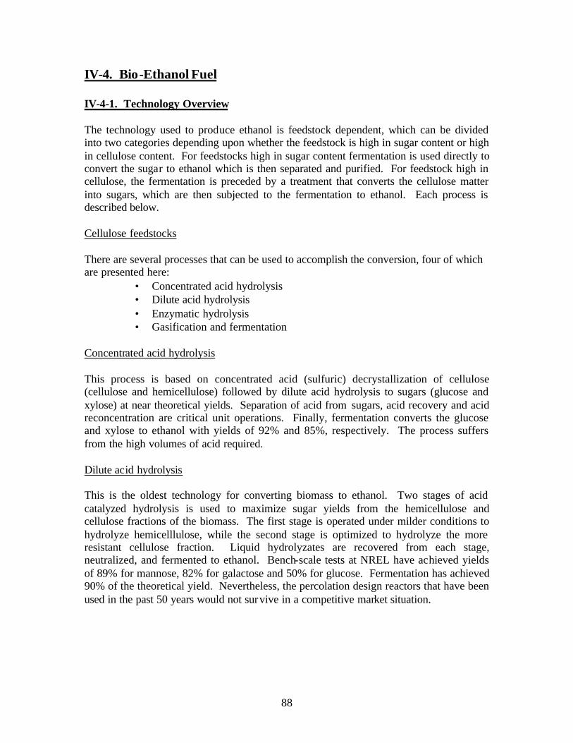
IV-4. Bio-Ethanol Fuel
IV-4-1. Technology Overview
The technology used to produce ethanol is feedstock dependent, which can be divided into two categories depending upon whether the feedstock is high in sugar content or high in cellulose content. For feedstocks high in sugar content fermentation is used directly to convert the sugar to ethanol which is then separated and purified. For feedstock high in cellulose, the fermentation is preceded by a treatment that converts the cellulose matter into sugars, which are then subjected to the fermentation to ethanol. Each process is described below.
Cellulose feedstocks
There are several processes that can be used to accomplish the conversion, four of which are presented here:
• Concentrated acid hydrolysis • Dilute acid hydrolysis • Enzymatic hydrolysis • Gasification and fermentation
Concentrated acid hydrolysis
This process is based on concentrated acid (sulfuric) decrystallization of cellulose (cellulose and hemicellulose) followed by dilute acid hydrolysis to sugars (glucose and xylose) at near theoretical yields. Separation of acid from sugars, acid recovery and acid reconcentration are critical unit operations. Finally, fermentation converts the glucose and xylose to ethanol with yields of 92% and 85%, respectively. The process suffers from the high volumes of acid required.
Dilute acid hydrolysis
This is the oldest technology for converting biomass to ethanol. Two stages of acid catalyzed hydrolysis is used to maximize sugar yields from the hemicellulose and cellulose fractions of the biomass. The first stage is operated under milder conditions to hydrolyze hemicelllulose, while the second stage is optimized to hydrolyze the more resistant cellulose fraction. Liquid hydrolyzates are recovered from each stage, neutralized, and fermented to ethanol. Bench-scale tests at NREL have achieved yields of 89% for mannose, 82% for galactose and 50% for glucose. Fermentation has achieved 90% of the theoretical yield. Nevertheless, the percolation design reactors that have been used in the past 50 years would not sur vive in a competitive market situation.
88

Enzymatic hydrolysis
In this process hydrolysis accomplished with cellulose enzymes and fermentation steps are combined which eliminated on of the process unit operations and avoids the problem of product inhibition associated with enzymes when the steps are separate. The high cost of cellulose enzymes is a key barrier to economical production of bioethanol from lignocellulosic material.
In Canada, Iogen Corportaion is constructing the first commercial scale cellulose ethanol plant using an enzymatic process. The plant is to produce fermentable sugars from 50 tons of wheat straw per week and be fully operational by 2005.
Gasification and Fermentation In this process the biomass is gasified to produce a synthesis gas (H2, CO, CO2) which is converted into ethanol with anaerobic bacteria. Figure IV-4-1 below shows this process.
Figure IV-4-1 Process Flow Diagram from Cellulosic Biomass.
89
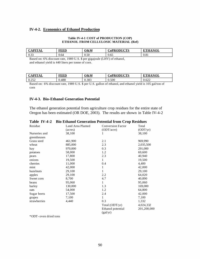
IV-4-2. Economics of Ethanol Production
Table IV-4-1 COST of PRODUCTION (COP) ETHANOL FROM CELLULOSIC MATERIAL (Ref)
CAPITAL FEED O&M CoPRODUCTS ETHANOL 0.33 0.64 0.50 0.65 0.81 Based on: 6% discount rate, 1989 U.S. $ per gigajoule (LHV) of ethanol, and ethanol yield is 440 liters per tonne of corn.
CAPITAL FEED O&M CoPRODUCTS ETHANOL 0.252 0.488 0.383 0.500 0.622 Based on: 6% discount rate, 1989 U.S. $ per U.S. gallon of ethanol, and ethanol yield is 105 gal/ton of corn
IV-4-3. Bio-Ethanol Generation Potential
The ethanol generation potential from agriculture crop residues for the entire state of Oregon has been estimated (OR DOE, 2003). The results are shown in Table IV-4-2
Table IV-4-2 Bio Ethanol Generation Potential from Crop Residues Residue
Nurseries and greenhouses Grass seed wheat hay potatoes pears onions cherries mint hazelnuts apples Sweet corn beans barley oats Sugar beets grapes strawberries
*ODT- oven dried tons
Land Area Planted Conversion Factor Total (acres) (ODT/acre) (ODT/yr) 38,100 1 38,100
461,900 2.1 969,990 885,000 2.3 2,035,500 970,000 0.3 291,000 58,000 1.2 69,600 17,800 2.3 40,940 19,500 1 19,500 11,000 0.4 4,400 42,000 1 42,000 29,100 1 29,100 29,100 2.2 64,020 8,700 4.7 40,890 95,060 1 95,060 130,000 1.3 169,000 54,000 1.2 64,800 17,500 2.4 42,000 7,100 1 7,100 4,440 0.3 1,332
Total (ODT/yr) 4,024,332 Ethanol potential 201,200,000 (gal/yr)
90

IV-4-4. Incentive Programs and Tax Credits
Federal fuel tax discount for ethanol gasoline blend
In 1978, Congress enacted a law to eliminate the $0.04 per gallon fuel excise tax on blends of 10 percent ethanol and 90 percent gasoline. Because ethanol comprises only 10 percent of the fuel blend, the effective subsidy to the 200-proof ethanol component is $0.40 per gallon. The exemption for ethanol blends increased to $0.06 from 1987 to 1990, but since 1990 has remained at $0.054. In 1998, Congress extended the federal fuel tax exemption until 2008, but the rate of the incentive decreased to $0.053 in 2001, and is scheduled to decrease further to $0.052 in 2004, and to $0.051 in 2005.
A 1980 Minnesota law reduced the state fuel tax on gasoline containing at least 10 percent ethanol by $0.04 per gallon. The fuel tax credit (usually called the blender’s credit) was reduced over a period of years and finally phased out entirely in 1997. The blender’s tax credit reduced revenues deposited in the highway user trust fund. In 1983, the fuel tax on gasoline purchased for use in government vehicles or for school transportation was reduced by $0.08 per gallon. This credit also reduced revenues for highway construction and maintenance, and was repealed in 1998.
Producer payments In 1986, the legislature created the “ethanol development fund” as a way to pay producers for ethanol produced. The original payment schedule was $0.15 per gallon of ethanol. The authorized amount has changed several times but typically has been $0.20 per gallon. Each plant is generally eligible for payments for ten years from the time a plant, or a plant expansion, comes on line, but not more than $3,000,000 per plant per year. The producer payment program is currently closed to new applicants, and payments to all plants are scheduled to terminate in 2010. The payment rate from 2004 to 2010 will be $0.19 per gallon.
Oxygenate mandate A 1991 law established mandatory use of oxygenated gasoline in air quality non-attainment counties after October 31, 1995. It also extended the mandate statewide after October 31, 1997. Later amendments of the law moved the oxygenate mandate up to 1992. In 1996, a further modification created exception to the statewide oxygenate mandate for motor sports racing, airports, marinas, motorcycles, off-road vehicles, small engines, and collector vehicles.
91

IV-5. Solar Energy
Solar energy is a renewable energy source that is clean and sustainable. In nature, solar energy is used in a process of photosynthesis to provide the energy needed to sustain life and is a vital part of the food chain. From the air we breathe, the plants and animals we eat, to the fuels we burn, solar energy has been an important part of man’s existence. Today, we can use the solar energy produced from the sun to either directly produce electricity in photovoltaic panels, or by using the energy in the form of heat and hot water. In order to better understand the potential energy from this resource, we have to evaluate the amount of energy, in what forms it can be used, how we can convert it into other forms, and a cost analysis to use this renewable energy source.
IV-5-1. Solar Resource
The Umatilla Indian Reservation lies to the east of the Cascade Range and 260 miles from the Pacific Ocean, and as such is in the rain shadow of the Cascade Mountains. The annual precipitation the reservation receives varies from 10-30 inches depending upon the location. The bulk of this occurs during the winter months as shown in Table IV-5-1 for the lower elevations located on the western portion of the Umatilla Indian Reservation.
Table IV-5-1 Average monthly and Annual precipitation in the Pendleton area in inches Jan Feb Mar Apr May Jun Jul Aug Sep Oct Nov Dec Ann 1.51 1.14 1.16 1.04 0.99 0.64 0.35 0.53 0.59 0.86 1.58 1.63 12.02
.
Likewise, most of the cloud cover also comes during the winter months as shown in Table IV-5-2. It is to be noted that the Pendleton Area data may substantially under estimate the irradiance on the UIR where the eastern portion of the UIR is at about 4000 feet elevation and above the inversion that often occurs for several weeks during the winter months. Thus the solar energy received on a substantial portion of the UIR may exceed the reported average for this area of 4.5-5.5 kWh/m2/day of solar radiation assuming the solar collectors are flat plate, fixed collectors, facing south with latitude tilt
92
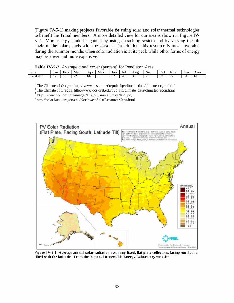
3
(Figure IV-5-1) making projects favorable for using solar and solar thermal technologies to benefit the Tribal members. A more detailed view for our area is shown in Figure IV-5-2. More energy could be gained by using a tracking system and by varying the tilt angle of the solar panels with the seasons. In addition, this resource is most favorable during the summer months when solar radiation is at its peak while other forms of energy may be lower and more expensive.
Table IV-5-2 Average cloud cover (percent) for Pendleton Area Site Jan Feb Mar Apr May Jun Jul Aug Sep Oct Nov Dec Ann Pendleton 82 80 72 66 61 52 26 33 40 57 77 84 61
1 The Climate of Oregon, http://www.ocs.orst.edu/pub_ftp/climate_data/climateoregon.html 2 The Climate of Oregon, http://www.ocs.orst.edu/pub_ftp/climate_data/clima teoregon.html
http://www.nrel.gov/gis/images/US_pv_annual_may2004.jpg 4 http://solardata.uoregon.edu/NorthwestSolarResourceMaps.html
Figure IV-5-1 Average annual solar radiation assuming fixed, flat plate collectors, facing south, and tilted with the latitude. From the National Renewable Energy Laboratory web site.
93

IV-5-2. Solar Technologies
Solar energy can be used in several forms. Some are more expens ive than others, but may have a high pay-back over a period of time. The energy of the sun can either be used directly, or indirectly to produce electricity. The direct forms of solar energy include “passive solar”, and “solar thermal.” An indirect use of the sun’s energy is the production of electricity with photovoltaic panels.
(Source: University of OregonFigure IV-5-1 Average annual solar radiation for the Pacific NW. Solar Radiation Monitoring Laboratory).
IV-5-2-1. Passive Solar
Passive Solar Heating in a home is a process where the design of the home is integral into trapping enough heat during the day to offset the cost of heating the home with other means. There are big payoffs in energy efficiency, thermal comfort, and conservation. However, the home must be properly oriented, have the right overhangs and shading, balanced window orientation and glazing with a thermal mass to store the heat, and the home should have good insulation and ventilation (Figure IV-5- 3). These are features that are best incorporated into a home during its construction.
94

This would be a viable option for future construction on the Umatilla Reservation, but it may be difficult and expensive to try to retrofit existing homes to meet these requirements. One of the recommendations from this report would be that any future development on the reservation, both domestic and industrial, considers the use of passive solar technologies in their design. Existing plans for these types of homes are readily available and the construction costs may not be more than a standard home. The big pay-off would be to the individual home owner with a lower yearly energy bill and to the earth. The challenge would be to get HUD housing and the Tribe to adopt the plans and to accept an energy efficient home as a standard design.
A passive solar home with overhangs to shade in the summer but allow sun in during the winter. Figure IV-5-3 .
A thermal mass slowly re-radiates the sun's energy during the night.
IV-5-2-2. Solar Thermal
Another way to use the sun’s energy economically is with sola r thermal process. A solar thermal system makes use of the warmth absorbed by the “flat plate” solar collector to heat water or another working fluid. Solar thermal energy is heat energy obtained by exposing a collecting device, usually made from a large, flat, insulated box with one or more glass covers, to the rays of the sun. Inside the boxes or tubes are dark colored metal plates that absorb heat or infrared energy (Figure IV-5-4). Air or liquid as the heat transfer fluid flows through a pipe system within the collectors and is warmed by heat absorbed in the plates. This system is good for providing household hot water. It is generally sized for use in an individual home rather than for industrial applications. 83% of households in Israel were using solar collectors by 1994.
95

Figure IV-5-4 . A flat plate solar collector for producing domestic hot water
An active solar thermal system is one where the exchange fluid is actively pumped from the storage tank through the collectors and back into the tank (Figure IV-5-5) 1 . An electronic controller, a small pump, valves and other components are needed for proper operation and for the ability to service the system. A heat exchanger is used between the hot fluid, and the domestic home water supply. Some systems will directly pump the domestic water supply through the solar thermal panels, but there is a danger of the water freezing at night or in the winter when the temperature drops and the sun isn’t out to heat the water. In cold climates or where freezing temperatures occur on a regular basis during the winter, a heat exchange system uses anti- freeze such as a non-toxic glycol solution to prevent damage to the collection system. On average, water heating comprises 14-18% of the home owner’s energy use2,3. These systems do not produce electricity directly, but they will save the homeowner money since other heat sources are not used to heat the domestic water supply. The home owner could see an even greater savings in their energy bill if the hot water is used as space-heating (or hydronic floor heating) for their home.
1 Marken, C. and Olson, K, 2003, SDHW Installation Basics Part 2: Closed Loop Antifreeze, Home Power #95, page 42-49. Also in: http://www.homepower.com/files/sdhwinstallparttwo95-42.pdf 2 http://www.eere.energy.gov/windandhydro/windpoweringamerica/pdfs/small_wind/small_wind_or.pdf 3 http://www.eere.energy.gov/femp/pdfs/FTA_solwat_heat.pdf
96

Figure IV-5-5 Parts of a typical solar domestic hot water system
Another way to get the energy of the sun into the working fluid for storage is with a concentrating solar reflector. The fluid flows through a tube mounted within a parabolic trough-shaped concentrator that reflects and concentrates the light back onto the receiver tube running through the focal point of the mirrored surface (Figure IV-5-6). This process is similar to how some solar cookers work. The transfer fluid can be heated to as much as 570°F (299°C) but is usually antifreeze or water for domestic water-heating systems. The hot water in the tube can then be stored in a hot water tank in a process similar to the flat plate collectors mentioned above. Parabolic-trough systems require a tracking system to keep them focused toward the sun to maximize the solar gain. They are also best suited to areas with high direct solar radiation. Parabolic-trough collectors
97

generally run unattended with minimal operation and maintenance requirements. These systems particularly benefit from economies of scale, so are generally used for larger systems such as for industrial and commercial applications4.
Figure IV-5-6 A concentrating solar reflector for producing hot water for domestic or commercial use.
There are several advantages and disadvantages to solar thermal systems which are itemized below.
Advantages:
• Solar thermal energy makes use of a renewable natural resource which is readily available in most parts of the world.
• Solar energy used by itself creates no carbon dioxide or other green house gases or toxic emissions.
• The heated fluid can be stored in insulated tanks, allowing energy to be used during brief cloudy or overcast periods.
• Use of solar thermal energy to heat water or generate electricity will help reduce the state's use of imported fossil fuels and hydroelectric resources.
• Oregon State offers tax incentives to offset the cost of buying and installing a solar thermal device which supplies hot water for single family homes or multi-unit residential buildings.
• Solar water heaters are an established technology, readily available on the commercial market, and simple enough to build, install and maintain by yourself.
4 http://www.eere.energy.gov/buildings/info/components/waterheating/solarhot.html
98

Disadvantages:
• Solar thermal systems are not cost-effective in areas which have long periods of cloudy weather or short daylight hours. Efficiency is also reduced by atmospheric haze or dust.
• In cooler climates, freezing can damage collecting system components, such as pipes, and have to be protected by using an anti- freeze solution in them.
• These systems only work with sunshine and do not operate at night or in inclement weather. However, storage of hot water for domestic or commercial use is simple, using insulated hot water tanks.
For the Umatilla Reservation, producing hot water from the sun would be one of the most economical forms of solar thermal energy for domestic use. If the solar thermal systems are large enough, they can also heat the home via radiant floor heating. This would further reduce the home’s energy usage. A solar thermal system may also be a good option to help lower the energy costs where the Tribe uses large volumes of hot water such as at the CTUIR’s Wildhorse Resort and Casino.
IV-5-2-3. Solar Photovoltaic
Photovoltaics, also known as PV, are panels or modules comprised of a series of solar cells that directly convert sunlight into clean solar electricity. The solar cells are made of thin layers of material, usually silicon, which absorbs the sunlight. The layers, after treatment with special compounds, have either too many or too few electrons. When light strikes a sandwich of the different layers, electrons start flowing and results in an electric current. A metal grid around the individual solar cells directs the electric currents into wires that lead to the power controls (Figure IV-5-7)5.
Diagram of a photovoltaic cellFigure IV-5-7
5 http://www.fsec.ucf.edu/pvt/pvbasics/index.htm
99

To get the most power out of the solar modules, the incidence of light should be at right angles to the face of the solar cells at solar noon. Solar noon is the time when the sun is the highest point in the sky. Thus, in the Northern Hemisphere for best results, the solar modules need to be mounted towards the true South, facing the sun and avoiding shade. Due to the sun changing its position in the sky with the seasons, the angle of tilt of these solar modules could be changed manually four times a year to get up to 10 percent more
6power . However, this additio nal gain may be small compared to the overall power produced from the panels if adjusting these panels is considered too difficult. Thus, the panels are usually set to the degrees of the latitude of the location where the panels are mounted. Alternatively, the panels could be angled to the local degrees of latitude plus 15 degrees to maximize the energy that would be produced from the winter sun when the energy demand may be the largest. If a solar tracker is used to follow the daily path of the sun from east to west, the user could see an additional 25 to 35 percent more power out of the PV panels during the day. However, the cost of installing a tracker may not be as economical as installing additional solar panels to produce that much more power. This is especially true if the homeowner has eight or fewer solar panels7
There are several advantages and disadvantages to a small-scale photovoltaic system for the home 8 which are listed below.
Advantages:
• Working photovoltaic systems are mechanically simple; there are no moving parts in PV cells so the cells need no maintenance other than periodic cleaning.
• PV cells have a long life with 20 to 25 year manufacturer guarantees. • PV cells generate direct-current electricity which can be stored in batteries
and used in a wide range of voltages depending on the configuration of the battery bank.
• The production of electricity by the photovoltaic process is quiet and produces no carbon dioxide or toxic fumes.
• Use of photovoltaics as a renewable source of ele ctricity will help reduce the state's use of imported fossil fuels and keep water in the river for the fish.
• Photovoltaics allow the use of electric lights and other equipment in isolated areas where connections to utility power lines are expensive or not available.
• Most electric appliances operate on alternating current, although some appliances are made to operate on direct current. Highly efficient and reliable inverters (which change PV-generated direct current electricity into the alternating current used in most homes and buildings) are now available at a reasonable cost.
• Oregon State offers tax incentives for the purchase and installation of photovoltaic and other solar equipment.
6 http://www.homepower.com/files/pvangles.pdf7 http://www.homepower.com/files/pvangles.pdf 8 http://www.hawaii.gov/dbedt/ert/pv_hi.html#anchor349152
100

• Photovoltaic systems are an established technology, readily available on the commercial market, and simple enough to install and maintain by the homeowner.
Disadvantages:
• Photovoltaic-produced electricity is presently more expensive than power supplied by utilities.
• Photovoltaic cells must have light to create electricity. Shade from clouds, trees or nearby buildings reduces the output from a PV system. Batteries must be used to store electricity for use during non-sunlight hours.
• PV systems which are connected to utility lines must provide power which is compatible with that of the utility and may require special interconnection equipment.
• Batteries need periodic maintenance and replacement. • Some of the materials used in the manufacturing of PV panels are toxic. • The PV panels may take up a large surface area depending on power needs.
Due to the cloud cover and inversions in this area during the winter, domestic use of only a PV system may not be practical or economic for most home owners. However, if this system is paired with other renewable energy sources such as wind to produce a hybrid system, it may be able to produce all the power the average home would need. This system is also ideal to offset homes or businesses that have high energy demands during the summer months.
IV-5-2-4. Concentrating Solar Energy
Another way to get energy from the sun into a form that can be used in the home is by focusing or concentrating the suns energy and applying this heat energy into an engine that then turns an alternator to produce electricity. The components to this system are few and relatively simple in design9.
A parabolic, mirror-covered satellite dish or “concentrator” reflects the heat of the sun back up to a small area. Since the sun’s energy is focused on this area, it is concentrated and can reach 1,200 degrees Fahrenheit or more. This energy can be used by an external combustion (Stirling) engine, for example, that uses heat to drive the engine (Figure IV5- 8).
9 http://www.energylan.sandia.gov/sunlab/overview.htm#dish
101

Figure IV-5-8 A Concentrating Solar Reflector uses the heat of the sun to run a Stirling Engine that generates electricity.
A Stirling engine is an “external” combustion engine. The heat energy expands a gas within the engine that drives a piston to make mechanical power. This gas is then diverted to another part of the engine where it cools, contracts, and the process begins again. These engines are sealed and have half the moving parts of a regular internal combustion engine. The Stirling engine uses the mechanical power to drive a generator that produces electricity.
Currently, these solar concentrating power systems are being developed to produce between 10 and 25 kilowatts of power for remote locations. However, since this is a green power system, it has high efficiencies, and uses “conventional” construction methods, these systems are expected to compete with other distributed power generation methods both on and off-grid. This is especially true in sunny locations like the Southwest U.S. However, they may also compete with photovoltaics in other locations like on the Umatilla Indian Reservation. The Stirling engine can be configured to run on other types of conventional fuels which makes it idea to use as a hybrid system. The Stirling engine may use water or other fluids to keep part of the engine cool. As a bi-product, this fluid would be used to produce domestic hot water for the home. Thus, one of these concentrating solar power systems serves the same role as both PV panels and a solar thermal system.
A variation on producing electricity from the sun with concentrating or focusing the sun comes from the Parabolic Trough. As was mentioned above, the trough heats up a fluid passing through a pipe at the focal point. However, instead of that pipe carrying water for domestic hot water, it could carry oil or liquid sodium. High temperatures (greater
102

than 392°F [200°C]) are produced with a large array10. This fluid then produces steam that drives a generator to produce the electricity. These systems are typically larger and more in line with industrial scale production of electricity. As such, this may not be practical on this reservation. In addition, during periods in the winter when the western portion of the reservation area has frequent inversion layers, very little if any power would be produced.
IV-5-3. Solar Economics
A typical home uses approximately 9400 kilowatt-hours (kWh) of electricity per year (about 780 kWh per month). Before choosing a renewable energy system for domestic or industrial use, the first approach would be to make the home more energy efficient, thus reducing the overall energy consumption. This would also be one of the most economical approaches to energy conservation. Replacing old appliances like refrigerators, furnaces, air conditioners, washers, and dryers, and freezers with modern, “Energy Star” compliant devices helps greatly in reducing the home energy bill.
IV-5-3-1. Passive Solar Economics
A Passive Solar home does not necessarily have to cost more than a non-solar home. However, it would take a concerted effort with HUD housing to find a design that is suitable for Tribal Members on the reservation. In general, a passive solar home can save the homeowners 40 percent on their electric bills with no increase in the construction costs11. One “expense” associated with a passive solar home would be the training that is associated with a construction crew and contractor on the process of building a passive solar home. This “training” would be as simple as orienting the long side of the house to receive the most sunlight, facing south in the north hemisphere, and placing most (50 percent) of the windows on this side. Additionally, overhangs would be built over the windows to shade them in the summer so the home doesn’t overheat. Many existing plans can already be used as a passive solar home if the home is oriented correctly.
Doug Boleyn, a professional engineer with Cascade Solar Consulting, has been monitoring the energy savings from a 2,500 square foot, two-story passive solar home built to 1974 energy standards. He has shown12, even without thermal storage in the home, that a passive solar home with 50 percent of the windows on the south side would save 15% or 3005 kWh over 4 winter seasons of 628 heating (sunny) days. A modern constructed, insulated and oriented home would save even more. This is with no additional cost in construction.
http://www.eere.energy.gov/build ings/info/components/waterheating/solarhot.html
11 Hayes, C., Reman, R., Still, S., 2004, Green Techniques & Solar Energy are Good for Business, in Green & Solar Homes Oregon a Comprehensive Guide to Green & Solar Building, p. 82.12 Boleyn, Doug, 2004, An Engineer’s Look at Measured Passive Solar Savings, in Green & Solar Homes Oregon a Comprehensive Guide to Green & Solar Building, p. 15.
103
10

IV-5-3-2. Solar Thermal Economics
A solar thermal system cost approximately 1/3rd to 1/4th that of a photovoltaic system depending on the type of solar thermal system installed. As an example summarized in Table 3, an inexpensive batch heater system could cost approximately $1,400 if the homeowner installed these themselves. Table 4 presents another example of solar domestic hot water system economics.13 A professionally installed Solar Domestic Hot Water system should cost, on average, between $2,000 and $3,000.
Table IV-5- 3 Solar Thermal Example 1 Item
AAA Solar heater, batch Shipping Valves, piping, etc. Total
$900 $400 $100 $1,400
Cost
Table IV-5-4 Solar Thermal Example 2 Item
Mor-Flow/American solar tanks, 120 gal 2 SunEarth EP-40 4x10 ft. collectors 1 Goldline GL-30 controllers with display 2 Grundfos pumps, various sizes 1 Heat exchanger 1 Solenoid valves Misc. electrical, insulation, & ducting 1 flow gauges 1 Temperature gauges 1 Tempering valve Total
$982.00 $1826.00 $320.00 $300.00 $125.00 $175.00 $500.00 $100.00 $20.00 $30.00 $4,378.00
Cost
Oregon Department of Energy and the Energy Trust of Oregon offer tax credits of up to $1,500 and rebates up to $1,000 for a solar water heating system. This is nearly half the cost of a solar thermal system14. Dollar for dollar, a solar water heating system for the home is five time more cost effective than a PV system. Additionally, a solar thermal system can be easily adapted to fit into exiting homes.
IV-5-3-3. Photovoltaic Economics
Use of photovoltaic systems in U.S. is a growing market. The growth rate is currently at 25% annually. This 25% rate is projected by DOE to be sustainable annually until at least 2020. However, this rate is low compared to overseas use of photovoltaics. For
13 Adapted from Sweetman, D., 2004, Solar Heating Three in One, HomePower issue 101, pages 72-78. 14 Patterson, John, 2004, “A Revolution in Solar Hot Water” in 2004 Green & Solar Homes Oregon – a comprehensive guide to green & solar building, p. 39.
104

example, in Japan, their use of photovoltaics has a growth rate of 63%. Worldwide, PV shipments grew by 32 percent in 2003 and an even larger growth was reported in 200415.
Currently, solar cells available on the open market have efficiencies of 15%-18%. This is how much of the available energy that strikes the panels is converted into electricity. Contractor installed systems cost about $10/watt or $10,000 per kW. A homeowner could build a PV system themselves; but due to the potential electrical hazard, a contractor should be consulted before final connection to their home. This is especially true if the system is grid-tied. One factor that adds to the cost of a PV system is whether it is connected to the electrical grid or not and whether the home system will use batteries to store power. The size of the system will also directly affect the cost.
Several examples of components and cost analysis for several PV systems are given below taken from Home Power magazine. Actual costs will vary depending on equipment brands, labor, location, size, etc. These costs also do not reflect rebates and tax credits which can be substantial.
Table IV-5-5 Photovoltaic System Grid-tied, 3792 Watts
System Components Cost 24 Kyocera 158 PV modules & shipping $12,010 2 Xantrex STXR-2500-UPG inverters $2,000 Rack, hardware, & concrete $767 Misc. electrical $313 240 Struts, A1200 HS-10-PG $290 Wire, #10 $103 8 MC cable extensions, 10 ft. $64 Auger rental $53 Stainless hardware $37 Total System $15,637
Table IV-5-6 Photovoltaic System Grid-tied, battery backup, 2,400 Watt System Components Cost 20 AstroPower 120-watt PV modules $15,700 Labor $5,390 Xantrex SW4048 inverter $3,250 Xantrex PC250 power center $1,495 8 Concorde batteries, 12 V, 100 AH $1,264 5 AstroPower 4-AP-1206 mounts $750 Two Seas battery box $408 Transfo rmer, 120 to 240 VAC $360 TriMetric battery monitor $328 Subpanel & breakers $285 5 junction boxes $264 Conduit & wire $230
15 Schwartz, J, 2005 What’s Going On – The Grid? A New Generation of Grid-Tied PV Inverters, Home Power issue 106, pages 26 -32.
105

Combiner box, 10 lug $229 Xantrex GFI option $149 Cable to stage, 30 ft. $133 Hardware for mount $125 Utility disconnect switch $120 Xantrex inverter conduit box $85 2 inverter cables $72 6 Battery interconnect cables $72 System manual (Solar Works) $25 Battery temperature probe $24 10 Fuses, 15 A $10 2 Cable Lugs $3 System Total $30,771
Table IV-5-7 Photovoltaic System Off Grid, 960 Watts System Components Cost 8 Kyocera KC120 PV modules $3,512 Xantrex SW4024 inverter $2,499 Generac 04389-1 generator $2,275 Wattsun AZ-125 dual-axis tracker $1,926 8 Rolls S-530 batteries $1,592 Misc. wire, cable, & conduit $447 Concrete for tracker $425 Load centers, breakers, & disconnects $400 Xantrex T240 autotransformer $289 Xantrex DC250 DC disconnect $241 Xantrex TM500 battery monitor $191 Pulse TCB combiner box $181 PV tracker pole $179 24 Water Miser battery caps $168 Xantrex C60 charge controller $161 Battery box materials $157 8 Battery cables $136 2 Inverter cables $94 DC breaker $50 DC lightning arrestor $35 AC lightning arrestor $35 CD 60 PV array breaker $30 Stainless battery hardware $23 4 Compression lugs $20 Freight $16 Total System $15,081
106

Table IV-5-8 Photovoltaic System Off Grid, 5,328 Watts System Components Cost 32 Photowatt PW 1000 PV modules $12,800 48 Surrette S-530 batteries $8,640 16 Sharp ND-L3E1U PV modules $6,900 2 Trace SW5548 inverters $5,900 Honda EM 6000 propane generator $2,650 Pulse PC 500 power center/charge controller $1,450 PV roof mounts, pipe, & materials $800 Battery cables $459 3 Pulse combiner boxes $375 Trace TM500 battery monitor $300 Installation, done by owner $0 Total System $40,274
The PV systems listed above, are typical of what a homeowner would expect to pay and the amount of power they could get from the system. There are opportunities on the Umatilla Indian Reservation for an even larger system. For example, the CTUIR Tamástslikt Cultural Center could use a solar car port to help offset some of their electrical needs. The Tribe’s golf course could power a fleet of electric golf carts with energy from a PV system. Even some of the street lights around the Wildhorse Casino could be converted into a solar lighting system with individual solar panels on each light.
A 30 KW solar car port application for the Tamástslikt Cultural Institute was investigated in the course of this work. The economics are presented in Table IV-5-9 where actual costs were quoted by SunWize Technologies, Inc.
Table IV-5-9 Photovoltaic System Grid-tied, 30 Kilowatts System Components Cost 30 kW ( AC ) grid tied solar carport system. $232,200.00 Electrical Installation , Prices set on a case by case basis $12,500.00 Structure Installation, Prices set on a case by case basis $35,000.00 Per Diem and Travel Expenses, Prices set on a case by case basis $10,000.00 O&M Manual Preparation, Prices set on a case by case basis $2,200.00 Engineering, Prices set on a case by case basis $7,500.00 Soils Test $4,000.00 Misc Electrical Parts $2,000.00 Total System $305,400.00
There are funding opportunities for the Tribes and Tribal members to help offset some of the costs for installing a grid-tied PV system. For homeowners and builders interested in generating their own electricity with solar electric (PV) systems, Energy Trust offers financial incentives as well as service and support. Incentives are up to $10,000 for homes and $15,000 for businesses. When combined with federal and state tax credits, the total cost of these systems can be lowered by 50% or more16.
“Free Cash Available to Help You Save Energy” in 2004 Green & Solar Homes Oregon – a comprehensive guide to green & solar building, p. 40-41.
107
16

For Tribal members who live on the reservation and do not have a tax liability, they may still receive a benefit in the form of a cash payment of 95% of the tax credit amount for a PV system by using a “Pass-through Option” where the tax liability is transferred to an Oregon business or resident who does have a tax liability.
IV-5-3-4. Concentrating Solar/Parabolic Trough Economics
In the southwestern United States, there is sufficient sunlight for parabolic trough collector systems to operate about 30% to 35% of the time. The systems will generally be most cost effective if sized so that on the best summer days they are just able to meet the hot water demands — that is, there is no excess capacity. Such a system can provide about 50% to 80% of annual water heating needs without fuel cost or pollution and with minimal operation and maintenance expense. Parabolic-trough collector systems can provide hot water at a levelized cost of $6 to $12 per million Btu for most southwestern areas. For this part of the country, the solar incidence is just over half of that of the southwestern U.S. (Figure IV-5-1). Thus the efficiencies would not be as great and/or the size of a system would have to be larger. However, these systems would work well during the summer months when the solar incidence is the highest.
Industrial Solar Technology (IST) of Golden, Colorado, was the sole manufacturer of parabolic-trough solar water heating systems. IST has an Indefinite Delivery/Indefinite Quantity (IDIQ) contract with FEMP to finance and install parabolic-trough solar water heating on an Energy Savings Performance Contract (ESPC) basis for any federal facility that requests it and for which it proves viable. Many facilities have used ESPCs and found them highly advantageous. For an ESPC project, the facility does not pay for any of the up-front costs, including design, capital equipment, installation or maintenance directly. Instead, they pay a share of the realized energy savings. This would be one way this reservation could benefit from this technology. Energy Concepts Company and Solar Kinetics/SOLOX appear to have also produced trough systems17.
For large systems the parabolic-trough collectors can be lower cost than flat-plate collectors. A typical system will reduce the need for conventional water heating by about two-thirds, eliminating the cost of electricity or fossil fuel and the environmental impacts associated with their use18. To make effective use of tracking systems and of the much higher temperatures that can be generated by a concentrating system, it is most cost effective to build a large system that will be used continuously. Typically, 3600 square feet of collectors (able to produce about 7500 gallons of hot water per day) would be the minimum size for a viable project. A parabolic collector array of this size would require land area of approximately 1130 square feet or an area of about 35’x35’19. Parabolic-trough solar water heating is therefore an effective technology for serving large facilities that operate 7-days-a-week and have a steady need for hot-water. An example of where
17 http://www.eere.energy.gov/femp/pdfs/FTA_solwat_heat.pdf page 24.18 http://www.eere.energy.gov/femp/pdfs/FTA_solwat_heat.pdf 19 http://www.energy.wsu.edu/ftp-ep/pubs/renewables/solar_coll_renew.pdf
108

this may be needed on the Umatilla Indian Reservation includes the Tribe’s motel, casino and truck plaza with its restraint facilities. The Wildhorse Motel’s laundry facility and swimming pool would especially benefit. Pool systems will often pay for themselves in just a few years and extend the pool season for the guests.
IV-5-3-5. Concentrating Solar/Stirling Engine Economics
The potential of solar electric power in the Southwest U. S. is comparable in scale to the hydropower resource of the Northwest. A desert area 10 by 15 miles could provide 20,000 MW of power, while the electricity needs of the entire U. S. could theoretically be met by an area 100 miles on a side. Concentrating Solar Power (CSP) was conceived as a means to harness this energy to provide large-scale, domestically secure, and environmentally friendly electricity20.
Early commercial trough plants produced power for about 35¢/kWh (in 2001 dollars) in niche markets. As continuing R&D improved plant performance and O&M costs and economies-of-scale for larger plants kicked in, power from the most recent plants dropped to about 11¢/kWh, the lowest-cost solar power in the world. While the costs of new plants built with advanced technologies may initially be slightly higher than this, they will drop rapidly with the construction and successful operation of the first few plants, demonstrating a learning curve similar to that seen at the SEGS plants and resulting in costs below 8¢/kWh within 5 years. Industry's trough technology roadmap lays out a detailed strategy to combine technology advances in receivers, reflectors and structures, thermal storage, and plant optimization to reduce costs to less than 5¢/kWh by 2015, making CSP fully competitive in global mega-markets21 (Figure IV-5-10).
Figure IV-5-10 Concentrating Solar Projected Costs
20 http://www.energylan.sandia.gov/sunlab/research.htm 21 http://www.energylan.sandia.gov/sunlab/research.htm
109

Of all solar technologies, dish/engine systems have demonstrated the highest solar-to-electric conversion efficiency (29.4%), and therefore have the potential to become one of the least expensive sources of renewable energy. They out-performed all other solar-to-electric generating systems by a factor of two, yet have comparable start-up costs. System installed costs, altho ugh currently over $12,000/kW for solar-only prototypes could approach $1,400/kW for hybrid systems in mass production. This relatively low-cost potential is, to a large extent, a result of dish/engine system’s inherent high efficiency.
The modularity of dish/engine systems allows them to be deployed individually for remote applications, or grouped together for small-grid (village power) or end-of- line utility applications. Dish/engine systems can also be hybridized with a fossil fuel to provide dispatchable power. This technology is in the engineering development stage and technical challenges remain concerning the solar components and the commercial availability of a solarizable engine22. Stirling engines, used with the reflective dish, are a leading candidate for dish/engine systems because their external heating makes them adaptable to concentrated solar flux and because of their high efficiency.
The environmental impacts of dish/engine systems are minimal. Stirling engines are known for being quiet, relative to internal combustion gasoline and diesel engines, and even the highly recuperated Brayton engines are reported to be relatively quiet. The biggest source of noise from a dish/Stirling system is the cooling fan for the radiator. Emissions from dish/engine systems are also quite low. Other than the potential for spilling small amounts of engine oil or coolant or gearbox grease, these systems produce no effluent when operating with solar energy. Even when operating with fossil fuel, the steady flow combustion systems used in both Stirling and Brayton systems result in extremely low emission levels 23. Satellite dish antennas have already been accepted by the public for aesthetic reasons. At a nominal maximum direct normal solar insolation of 1000 W/m , a 25-kW dish/Stirling system’s concentrator has a diameter of approximately 10 meters.
Over the next 5 to 10 years, only evolutionary advances are expected. The economic viability of dish/engine technology will be greatly enhanced if an engine capable of being “solarized” (i.e., integrated with solar energy) is introduced for another application. With the costs and risks of the critical power conversion unit significantly reduced, only the concentrator, receiver, and controls would remain as issues. Given the operational experience and demonstrated durability and reliability of the remaining solar components, as well as the cost and performance capabilities of dish/engine technology, commercialization may appear attractive to some developers and investors. The modularity of dish/engine systems will help facilitate their introduction. Developers can evaluate prototype systems without the risks associated with multi-megawatt installations.
Dish/engine systems are not now commercially available, except as engineering prototypes. Solar thermal dish/engine technologies are still considered to be in the
22 http://www.energylan.sandia.gov/sunlab/PDFs/solar_dish.pdf 23 http://www.energylan.sandia.gov/sunlab/PDFs/solar_dish.pdf
110

engineering development stage. Assuming the success of current dish/engine joint ventures, these systems could become commercially available in the next 2 to 4 years. Since they are not readily available now, it would not be in the CTUIR’s best interest to purchase the components for one unless it is for research and development purposes; not for power production. A potential market opportunity would be in the production of small-scale solar concentrating dishes to produce electricity for the individual home owners.
IV-5-4. Solar Recommendations
One recommendation from this feasibility study would be that any future housing, Business Park, or Government Building should incorporate a passive solar design to offset energy needs and benefit the environment that the Tribe depends upon.
One recommendation from this feasibility report is that a solar thermal system should be purchased for the installation as a demonstration project. An individual’s home, the Tribe’s longhouse, or a business would need to have records on their energy usage requirements for production of hot water and their overall energy usage. These records would then be used for comparison after a solar thermal system was installed. This would give the economics and rate of return on the investment for this project.
Another recommendation would be that any future development or construction for the infrastructure of the Tribe (such as a Government Building) should also incorporate a solar thermal system. This not only would save money in the long-term, but it would also be beneficial to the environment.
As a recommendation from this feasibility study, the Tribe should seek grant money to set up a demonstration PV system. Opportunities for this demonstration project include Tribal buildings such as the Tamástslikt Cultural Institute, Mission Market, the Tribe’s Longhouse, or even an individual’s home where tours and classes could be given on the benefits of a PV system. Once again, records on energy usage of the home or business would be needed before and after the system installation to be used as a comparison for the economics and rate of return on the investment for this project.
111
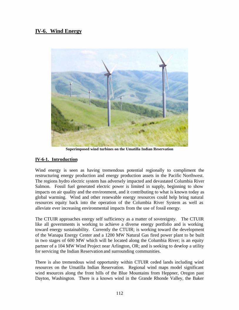
IV-6. Wind Energy
Superimposed wind turbines on the Umatilla Indian Reservation
IV-6-1. Introduction
Wind energy is seen as having tremendous potential regionally to compliment the restructuring energy production and energy production assets in the Pacific Northwest. The regions hydro electric system has adversely impacted and devastated Columbia River Salmon. Fossil fuel generated electric power is limited in supply, beginning to show impacts on air quality and the environment, and it contributing to what is known today as global warming. Wind and other renewable energy resources could help bring natural resources equity back into the operation of the Columbia River System as well as alleviate ever increasing environmental impacts from the use of fossil energy.
The CTUIR approaches energy self sufficiency as a matter of sovereignty. The CTUIR like all governments is working to achieve a diverse energy portfolio and is working toward energy sustainability. Currently the CTUIR; is working toward the development of the Wanapa Energy Center and a 1200 MW Natural Gas fired power plant to be built in two stages of 600 MW which will be located along the Columbia River; is an equity partner of a 104 MW Wind Project near Arlington, OR; and is seeking to develop a utility for servicing the Indian Reservation and surrounding communities.
There is also tremendous wind opportunity within CTUIR ceded lands including wind resources on the Umatilla Indian Reservation. Regional wind maps model significant wind resources along the front hills of the Blue Mountains from Heppner, Oregon past Dayton, Washington. There is a known wind in the Grande Rhonde Valley, the Baker
112

Area and south of the Wallowa Mountains. Many these areas are near a very crowded transmission system that travels west to east across the ceded lands to Brownlee Dam that delivered to Idaho Power and Light. Other areas with suspected wind resources are currently stranded away from existing transmission infrastructure.
CTUIR electricity consumption peaks at about 3.5 MW in August and January the hottest and coldest part of the year. The community is growing has specific economic development and energy goals including utility development and in the future may consume as much a 10 MW. Initially the CTUIR believes it is feasible to produce 20% of their current energy needs from renewable sources. Energy self sufficiency and sustainability are ultimately a goal of energy independence and sovereignty. This portion of the renewable energy feasibility study considers wind energy throughout the Columbia Basin but focuses on wind assessment within the boundaries of the Umatilla Indian Reservation.
Figure IV-6-1 Wind speed at 50 meters above the Umatilla Indian Reservation and CTUIR ceded lands.
113

VI-6-2. Wind Development – National, Regional and Local
VI-6-2-1. National Wind Development
It is estimated that the US has enough wind resources to generate 3500 gigawatts (GW) of wind power, and has installed only 2.6 GW. Most installed wind power capacity is located in western and mid-western states. North Dakota alone has a large enough wind resource to have met one-third of total national energy consumption. Three states: North Dakota, South Dakota, and Minnesota could have met three-fourth of US 1990 electricity needs (Green Power Market Group). Tremendous technical progress has been made in the design, siting, installation, operation, and maintenance of power-producing wind machines (turbines). These improvements have led to higher wind conversion efficiencies and lower electricity production costs. The cost of a kW-hour (kWh) from a new wind turbine is now between $0.03-$0.06, with some windy areas offering power possibly below .03 at the generation site (costs to the end customer vary) (Green Power Marketing Group). Further information can be found at www.thegreenpowergroup.org.
Since wind currently provides less than 1% of our Nations energy it is seen as having immense growth potential. Although wind is intermittent the existing electrical power generation and transmission infrastructure can be configured to accommodate this viability. The Department of Energy has developed a wind resource map for the United States. Goldman Sachs, the global investment banking and securities firm has invested in wind projects. Many other countries have also invested significant resources into wind. Europe has the goal of 17,000 MW installed by 2007.
The States of California, Texas and Minnesota are leading the United States in wind in installed capacity. California only has meager wind resources but leads the nation. Minnesota’s wind energy development is supported by state legislation in which wind production is being used to offset the storage of nuc lear waste. As fossil fuels are nonrenewable, finite energy resource expected to be largely depleted by the end of the 21st
century, causing environmental problems many state governments and utilities are aggressively diversifying their energy portfolio. In one presentation attended as part of this research effort a Pacific Power Marketing manager explained the utility has conservatively estimated that many natural gas sources have moved beyond their peak and over half the resource is gone sparking an initiative to use wind to help balance gas consumption..
The Intertribal Council on Energy Policy (Intertribal Coup) has taken the lead on wind development issues in Indian country. Based in the Great Plains where very significant amount of wind resources are known to exist. As an organization they have been instrumental in educating, disseminating information, policy analysis and assisting members to get involved in wind and power production issues. As an Indian entity they have taken the lead in national energy policy in Indian country. They primarily address issues within the Western Area Power Administration (WAPA) but are involved in analysis of national energy policy and Indian country (i.e. “The Energy Bill”); seeking
114

transferable production tax credits for Native American Projects; and energy independence for Indian Country, www.energyindependenceday.org.
IV-6-2-2. Regional Wind Development
There is significant wind development and energy speculation within the region. It is estimated that the Pacific Northwest has the potential to generate 133,000 average megawatts (MW) or more of electricity from wind (RNP 2002). It has been estimated that Oregon has the potential 4,900 aMW of electricity production from wind (RNP 2002).
There are infrastructure constraints to wind energy development in the region. Transmission is a major constrain, both load capacity and lines. The BPA proposed McNary-John Day transmission line of 160 miles will be required to move large quantities of electricity generated on the UIR to markets. An upgrade of this nature may be as much as 95 million dollars (Schienbien 2004). In order to supply the tribal needs distribution system upgrades will be needed as well.
Several wind projects listed below are operational on the Columbia Plateau including one that provides electricity to Pacific Northwest customers.
• Vancycle Canyon 25 MW of Vestas 660 kW since 1998.
• Klondike Wind Project (24MW) is owned by Pacific Power Marketing (PPM) Energy with a 20 year power purchase agreement with BPA. Uses 16 variable speed and pitch 1.5MW General Electric Turbines. Today 75 more MW are being installed.
• Condon Wind Project (49.8MW), Condon Oregon is owned by Goldman and Sachs and Sea west Northwest Asset Holding LLC (25%) with a 20 year power purchasing agreement with BPA. Project consists of eighty three, 600kw Mitsubishi Wind turbines.
• Nine Canyon Wind Project (66 MW) near Kennewick Washington is owned and operated by energy northwest. Power is sold to nine project investors primarily Public Utility Districts. This project employs Bonus 1.3 MW wind turbines.
• Stateline Wind project (300 MW+ ) is located on the ridges above the CTUIR’s ancient travel route through Van Cycle Canyon to the Columbia River 20 miles from the Mission, Oregon. Developed in 2001 and 2002. This development is owned by Florida Power and Light (FPL). Pacific Power Marketing bought the entire out put and has a 25 year power purchase agreement with BPA for some of that power. This project consists of 454 Vestus 660kw wind turbines.
• Foote Creek I (41.4 MW) is located in Wyoming is owned by PacifiCorp and Eugene Water and Electric Board. This project was built in 1996. BPA has a 25
115
year power purchasing agreement for 25 years to purchase 37% of the power. Sixty nine 600kw Mitsubishi wind turbines.
• Foote Creek II (1.8 MW) is a 3 turbine addition also built in 1996 to Foote Creek I also located in Wyoming is owned by Foote Creek II LLC and operated by Seawest Wind Power. BPA has a 15 year power purchase agr eement. Three 600kw Mitsubishi Heavy Industries Wind Turbines.
There are several other proposed projects within the region and others being investigated. These include but are not limited to Zintel (50 MW) Foote Creek III and IV; Rock River (50 MW); Evanston; Fossil Gulch (10 MW); and Combine Hills (41 MW).
IV-6-2-3. Federal Government
The CTUIR has a long term relationship with the federal government and its agents. The Department of Energy is the primary agent for energy issues however there are increasing overlaps in funding opportunities in renewable energy from between federal government programs in particular between DOE, the Department of Interior and Department of Agriculture. The CTUIR has benefited from DOE’s partnerships with Native America. Indian people represent less than 1 percent of the U.S. Population. The Federal Government has responsibility to assist tribes and sustainability in Indian country could be a way the U.S Government demonstrates a positive fiduciary relationship.
The National Renewable Energy Laboratory is very progressive in providing assistance and hands on training in renewable energy development. This renewable feasibility study is one of many examples of the assistance to American Indian Tribes provided by NREL’s Tribal Energy Program. The CTUIR has benefited from funding, training, consultation and technical assistance from NREL including the Wind Energy Applications Training Symposium and hope to be able to utilize NREL’s anemometer loan program for the next phase of the work. The CTUIR benefited from the DOE National Laboratory system, receiving wind energy development technical assistance from DOE’s Pacific Northwest National Laboratory. Tribes need to find ways to work together to ensure success of the program.
The CTUIR is continually involved in energy and natural resources issues surrounding the operation of Columbia River Hydro-system and has built a strong partnership with the USDOE Bonneville Power Administration. Institutionally BPA has a leadership role in the regions energy future. They have been instrumental in the development of wind projects in the Pacific Northwest and have invested directly into several of the aforementioned wind projects through power purchasing agreements.
BPA is continually involved in strategic planning that includes conservation and renewable energy issues. All potential energy development including wind in the region is directly tied to BPA’s operation of the hydro system and transmission capacity. All large scale electrical energy development in the Pacific Northwest is limited by the federal governments aging infrastructure that was established predominately to get hydro
116
electricity to customers. Commercial wind of scale was not realized at the time the regions transmission was developed therefore not a factor in building the Pacific Northwest energy infrastructure over the last century. The region now has the opportunity to look at wind as reinvestment and redesign of the regions aging infrastructure.
The CTUIR has begun to participate more directly in BPA’s regional dialogue and other discussions about efficiency, renewable energy, and conservation. BPA is focusing on fostering markets for renewable energy (BPA 2004). BPA is currently delivering 325 MW of installed wind energy through 37 northwest utilities (BPA 2004). In addition Bonneville personnel have provided key information and opportunities in assisting Tribes. BPA has directly assisted in the acquisition of a 50 meter wind monitoring tower with multilevel instrumentation which will be deployed in the next phase of the CTUIR renewable development.
IV-6-2-4. Oregon State
The Oregon Office of Energy has established the Oregon Wind Working Group (OWWG). Although the CTUIR is unable at this time to participate actively with this group the CTUIR has benefited immensely from information and contacts stimulated by this groups activities. Some of the goals of the OWWG expressed in it’s “action plan for Achieving Strategic Objectives” are
• to improve opportunities for small (<20 MW) wind projects • to evaluate renewable portfolio standards • to streamline the permitting process • to work with stake holders by developing and providing information on all phases
of wind development • to work to reduce transmission limitations • to assist in the development of more locally owned small wind farms • to provide adequate wind measuring equipment and technical support.
Oregon has also developed specific legislation and an Oregon Business Energy Tax Credit. Wind energy and tax credits are authorized by ORS 469.185 to 469.225 OAR 330-090-0105 to 330-090-0150 (for ORS 469.185; 315.354; 315.356.
To qualify for these state incentive programs 1) you must be a trade business, or rental property owner that pays taxes for a business site in Oregon, 2) you must own or be the contract buyer of the business, 3) The equipment must be used by you or leased to another person or business in Oregon. In addition there is a pass through option for nonprofit organizations. The Tribes status as a sovereign government negates the benefit of these state incentive programs.
117
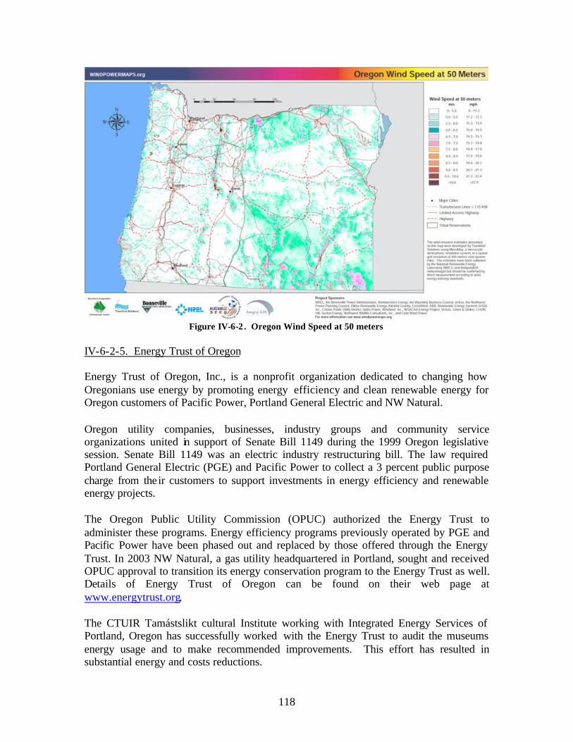
Oregon Wind Speed at 50 metersFigure IV-6-2 .
IV-6-2-5. Energy Trust of Oregon
Energy Trust of Oregon, Inc., is a nonprofit organization dedicated to changing how Oregonians use energy by promoting energy efficiency and clean renewable energy for Oregon customers of Pacific Power, Portland General Electric and NW Natural.
Oregon utility companies, businesses, industry groups and community service organizations united in support of Senate Bill 1149 during the 1999 Oregon legislative session. Senate Bill 1149 was an electric industry restructuring bill. The law required Portland General Electric (PGE) and Pacific Power to collect a 3 percent public purpose charge from the ir customers to support investments in energy efficiency and renewable energy projects.
The Oregon Public Utility Commission (OPUC) authorized the Energy Trust to administer these programs. Energy efficiency programs previously operated by PGE and Pacific Power have been phased out and replaced by those offered through the Energy Trust. In 2003 NW Natural, a gas utility headquartered in Portland, sought and received OPUC approval to transition its energy conservation program to the Energy Trust as well. Details of Energy Trust of Oregon can be found on their web page at www.energytrust.org.
The CTUIR Tamástslikt cultural Institute working with Integrated Energy Services of Portland, Oregon has successfully worked with the Energy Trust to audit the museums energy usage and to make recommended improvements. This effort has resulted in substantial energy and costs reductions.
118

IV-6-2-6. Washington State
Washington State University has taken a lead on establishing a Washington Wind Working Group. Many people in the region including those from the State of Washington attend the Oregon and Idaho wind working groups. Washington has several wind projects up and running and several more being planned. Industry and utilities have set the pace for development in wind power although Washington State Department of Natural Resources has expressed an interest in using State trust lands for wind. Some of the CTUIR ancestral homelands and trust land is in the State of Washington. The Tribe’s usual and accustomed area extends well into the south eastern portion of the state.
Figure IV-6-3 Washington Wind Speed at 50 meters
IV-6-2-7. Utilities
Pacific Power is looking to diversify its energy portfolio to include renewable sources. Aside from seeking viable sources of renewable energy they contribute to the Oregon Energy Trust which empowers ratepayers or consumers to seek energy conservation and renewable options for their energy needs including providing the option for net metering. Pacific Power provides services to the Umatilla Indian Reservation and has transmission and distribution capacity as well as the Round up Sub-Station located on the western boundary of the Reservation. PacifiCorp does purchase wind power and is purchasing the output of the 104 mw Columbia Wind Energy project. Part of the success of this project in completing a Power Purchase Agreement with PacifiCorp is the availability of transmission from the generation site to the energy trading hub along the Bonneville
119
system at the John Day Dam (the so-called “Big C.”) Transmission from that hub east to the Reservation is constrained, and new transmission access is reportedly not available.
Umatilla Electric Cooperative (UEC) is a rural electricity cooperative that relies on the regions affordable hydro electric power. They are also a member of PGNC that allows them to buy power on the open market as rates may dictate. They do provide the option for their customers to buy green power on the open market but at his time are reluctant to develop wind energy as their origination is the hydro system. They retain the first right to federal hydro system. Umatilla Electric Cooperative has stated that they would allow net meter billing (purchasing excess power from a wind generation facility located at an existing load) so long as the wind generator would pay for incremental costs of monitoring wind on their system, and for any necessary integration facilities. These costs would need to be determined through the load study and interconnection agreement process. The load study would need to be paid by the developer, not by the utility. They provide distribution to customers on the Umatilla Indian Reservation and maintain the existing infrastructure which includes a 10MW substation at Mission served directly by USDOE-BPA and another located on the reservation border at Pendleton.
Energy Northwest is a public power joint operating agency founded in 1957 that includes the membership of 17 Public Utility Districts and Municipalities. They have a vision of meeting the needs of the rate payers in the Pacific Northwest. They operate the regions only nuclear power plant and Nine Canyon south of Kennewick, Washington within the CTUIR ceded homelands. The wind farm uses Bonus1.3 MW wind turbines. They are involved in several renewable energy projects including solar, and biomass. They have developed a corporate focus on the development of energy projects with renewable being the current focus. Their infrastructure does not service the Umatilla Indian Reservation but they represent local expertise in wind project development. Energy Northwest wind/renewable projects represents a local wind energy resource that the CTUIR may be able participate through equity partnerships especially as the CTUIR seeks to realized its utility development goals.
Florida Power and Light Energy (FPLE) is among the largest and fastest-growing electric utilities in the United States. In 2003, the company’s average number of customer accounts grew by more than 97,000, or 2.4 percent, to more than 4.1 million (www.fpl.com). FPLE in partnership with Pacific Power Marketing (PPM) has developed the nations largest wind farm along the state line border between Washington and Oregon. This area is located immediately north of the Umatilla Indian Reservation along an ancient travel route to the Columbia River within the homelands of the CTUIR. The raw power is utilized by PPM to develop and shape green energy products to customers. The project sells 90 MW to BPA, 175 MW to Seattle City and Light, and 20 MW to Eugene Water & Electric Board (EW&EB). Their infrastructure does not serve the Umatilla Indian Reservation, however the CTUIR have been actively involved in the cultural resources management of the Stateline wind farm project, gaining tremendous experience in the process.
120

Idaho Power is involved in generation, purchase, transmission, distribution, and sales of electricity, serving over 20,000 square miles of Idaho and Eastern Oregon. They rely heavily on hydro-power on the Snake River. There are incentives in Idaho for renewable and small scale projects. Through state of Idaho rules, Idaho Power provides net metering opportunities. They are also involved in the development of the Fossil Gulc h Wind project near Hagerman, Idaho. They receive energy from Bonneville in La Grande Oregon and serve customers within the CTUIR ceded lands and usual and accustomed areas. They are seeking a project in eastern Oregon on the Grande Ronde Valley. It is unknown if they would be interested in a wind project at the CTUIR up wind of their service area.
IV-6-3. Wind Energy Economics and Incentives
Recent advances in wind energy technology have made wind energy more viable than ever before. The cost of electrical energy production from wind has fallen about 80% since the early 1980’s. Real costs are about 4-6 cents per kilowatt hour. Wind development requires financing, transmission, infrastructure, and wind quality. With effort and ambition it takes approximately 3 years if not longer to get a wind project from concept to reality. Estimated cost for a 250 kW turbine can range from $200,000-$300,000 or more. It is too early to estimate potential power production, total project cost, and cost savings without knowing more about the quality of the wind at these sites.
The most economical wind projects require a wind capacity factor of 30 percent or more and at least 35 towers that can produce 25 MW or more. It costs approximately one and a half million dollars MW per installed 1 MW wind turbines. The U.S. Congress has extended for one year through December 2005 the wind energy production tax credit to assist in the growth of the wind industry. The continuation of that credit is very important to provide wind an opportunity to exist in the subsidized environment of energy production. Currently people are working to extend this for five years and other are seeking a tribal energy credit. Oregon does provide personal and business tax credits for renewable energy projects and has assisted in long term low costs financing, and technical advice.
Currently one of the biggest issues in financing wind projects is the value of the dollar on the international market. Currently the value of the Danish currency makes the purchase of Bonus and Vestas wind turbines with U.S. dollars less competitive. Because of the exchange rate the Mitsubishi and General Electric wind turbines are more economical. This is unfortunate because of the known local performance and experience has been with the Danish wind turbines. General Electric turbines have established a strong reputation for performance. This does however create an opportunity and incentive for other wind turbine manufactures and customers to get good high performance products on line. The price of steel is also up 40% making production of turbines more expensive. Rising fuel costs also make transportation more costly.
If all social and environmental impacts of energy production were included in economic evaluation, wind would be among the cleanest and most cost effective sources of energy.
121

Wind though is an intermittent source of energy and seems to make the most sense when coupled with another energy source in order to level its intermittence. As the technology continues to improve and the full benefit of using wind energy becomes acknowledged we anticipate utilities adding more to there energy mix.
IV-6-4. Environmental Attribute Value
The following discussion is based entirely upon the work and material of the Inter Tribal Council on Utility Policy (Intertribal Coup). The extra cost that may be incurred by the production, transport and use of wind electrical energy is subsidized by Green Tag buyers. Green Tags can be sold into a Cap and trade CDM or other Carbon Market Programs in effect placing a quality value on the way the electricity is produced with the lest environmentally friendly, sustainable, less polluting have a greats value. Thus in effect allows energy producers to continue to pollute over the regulatory cap at other sites by buying the tags to become ‘clean on paper.” Or they can be sold to downwind supporters of renewable energy, retired, and taken out of market circulation. Essentially though the green tags or carbon credits have value and can aid in the financing of renewable projects. There are also negative characteristics of this public policy.
Tribally owned projects are not eligible for Federal Production Tax Credits (PTC) or the Renewable Energy Production incentives (REPI) or other tax based state incentives because of their special status as sovereign governments. PTC requirements penalize private partners in a tribal joint venture by limiting the credit. A Tribal Tradable Energy Production Incentive (TEPI) has been proposed as a means to level the playing field. (Intertribal Coup).
Wind turbines do create several revenue sources. Renewable incentives again are penalized in the current rules which need to be revised for Indian country. Wind projects do produce grid compatible (generic) electrical energy which can be transported and used anywhere. Wind projects may also take advantage of the net metering program the many states and utilities offer. There has been some discussion of whether a green project by Tribes may have some additional value over non-tribal green projects and thus the product might be worth more.(Intertribal Coup).
Perhaps one of the best incentives is the ability to utilize wind energy in agricultural areas. Much of the Umatilla Indian Reservation lies in a rural area where agriculture and silviculture on prevalent and agricultural is especially prevalent on the North Reservation where part of the CTUIR where high quality wind resources have been identified. Farmers are able to grow crops around the towers as the foot print is relatively small (510%, Nelson) and infrastructure can be buried below ground. This may also benefit the management of CRP or CREP lands taken out of production. Some lands that are part of these conservation measures on the UIR are known to be in the vicinity of good wind resources. As there is also non-Indian land ownership within the agricultural areas of the reservation there may be opportunities for partnerships or cooperatives.
122

Over the past several years, CTUIR has met numerous times with staff from BPA, local utilities, wind developers, and NREL regarding potential wind development on the Reservation. The following summary draws on these discussions.
IV-6-4-1. Power Purchase
Once the wind resource has been assessed and the interconnection costs identified, the developer can begin to estimate the cost of the wind power, and can begin to market the project at that price. The transmission assets determine to a large degree what the available market is for wind power.
Wind projects are financially viable when a Power Purchase Agreement (PPA) will finance the costs of a project. Before a PPA can be reached, a wind developer has to determine:
• Wind quality (how much power can be generated) • Interconnection agreement (how the power would be integrated into the existing
generation and distribution system) • Power purchase agreement (who will buy the power) • Project development costs and project financing
Prior to the feasibility study on a wind project, a potential wind deve loper needs to: • Work with meteorologist to install met towers in potential site locations • Collect and analyze wind data for at least one year • Establish potential power sales and price potential • Identify potential subsidies for project financing • Work with local utility to determine line load capacity
There are two general options for both interconnection and power sales: commercial, in which power is sold on the market and distributed over the grid to end customers; and distributed generation, in which power is generated at or near the site at which it will be used.
IV-6-4-2. Commercial Generation
Wind is still prohibitively expensive in comparison to non-renewable sources of energy, and the federal wind and state incentives makes wind projects feasible. Transmission capacity is a significant challenge for any commercial scale wind projects on the Umatilla Indian Reservation. Capacity on the Bonneville system between north of John Day or west of McNary (BPA, January 2004) is constrained. Reportedly there is no excess capacity on the 230 kV BPA line that crosses the Reservation, but the customers who have purchased the capacity on that line (Idaho Power and Light and Oregon Trail Electric Cooperative) could choose to purchase power from a CTUIR commercial wind project instead of from the BPA system. Reportedly, neither utility has any requirement to purchase wind power and has not expressed interest in doing so.
123

A load study is an analysis performed by a utility to determine how the utility could transmit the power over its own infrastructure, and is required prior to a utility signing an interconnection agreement with a wind (or other energy) developer. Load studies can be prohibitively expensive for small wind development .
Prior to requesting a load study, a wind developer needs to know how much wind they would be generating and when. This information has to be based on meteorological data but also needs to take into account the proposed turbine size and its known name plate capacity.
New commercial scale wind generation facility on the Reservation would need to include the costs of new transmission facilities to a trading hub before it could secure a power purchase agreement, unless existing customers on the BPA 230 kV line agreed to purchase power as describe above. At roughly $1 million/mile for new transmission construction, this requirement adds significantly to the difficulty of developing viable new wind generation on a commercial scale, and highlights the benefits of identifying generation sites with good wind potential that are adjacent to transmission routes with excess capacity.
IV-6-4-3. Distributed Generation
Wind generation on the Reservation could also be used for distributed generation. Two models seem viable. A wind turbine near a major power user such as the tribes resort or proposed light industrial park is one example. Or similar to the way other nations approach to distributed energy by using commercial wind farms to support local energy needs in surrounding communities rathe r than sold to end users that require wheeling energy long distance with charges. Power purchase agreements is another. The former would require very little transmission development the latter would require some infrastructure upgrades.
For example, a wind turbine located at the site of a power user such as Wildhorse Resort could generate power for that user, reducing the amount of power that the Resort would otherwise need to purchase off of the grid system. Regulated utilities such as PacifiCorp also support net meter billing, or the sales of excess power back to the grid. PacifiCorp is obligated to purchase this power at the avoided cost, or the cost they would otherwise pay to purchase power, even if the generation cost is higher than the avoided cost. Since PacifiCorp relies on a variety of generation facilities including coal, natural gas, and hydro, the avoided cost at $0.03/kilowatt is likely to be lower than the cost of wind production.
One option for wind development on the Reservation is production of power at the loads themselves, so that distribution is not required. Ideally, these facilities would be located at or near the largest electrical loads on the Reservation to maximize economies of scale. These loads would include the mission governmental complex, Mission housing, and the Wildhorse Resort. The quality of wind is not known at any of these sites, but is estimated at Class 2 (“Marginal”), according to NWSEED maps.
124

The final option for CTUIR is to construct and operate our own distribution system on the Reservation. This would require “overbuilding” existing UEC and/or PacifiCorp facilities, and obtaining both right of way and environmental clearance.
IV-6-4-4. Developing Wind Power on the Reservation
For commercial wind projects to move forward on the Umatilla Indian Reservation here must be some level of commitment by the Board of Trustees to seek information necessary for such a project. Amongst other things this means approving the research necessary for wind data gathering and completing applications and issuing the appropriate permits. The Tribe must also have an understanding of the CTUIR’s energy needs, customers it would serve, and infrastructure limitations.
Prior to any decision the CTUIR needs to systematically place anemometers at locations where there is an energy need and suspected wind resources. Based on wind reference maps the CTUIR has potential for large scale commercial wind projects or small scale projects sited near load demands.
The lack of transmission capacity on the Reservation means that commercial wind development would require significant upgrades or construction of new transmission facilities to a market. The cost of this new facility makes this type of development economically challenging, since the cost of the transmission facilities would price the power beyond the ability of available subsidies to compensate for high generation costs relative to the market. As market conditions change, this calculation will change.
IV-6-5. Wind Resources
IV-6-5-1. Preliminary Wind Assessment on the Umatilla Indian Reservation
In a project sponsored by the NREL, BPA, the Northwest Sustainable Energy for Economic Development (NWSEED) and the Northwest Cooperative Development Center (NWCDC) conducted and assessment and evaluation of wind speeds throughout the Pacific Northwest including the Umatilla Indian Reservation. The estimates have been validated by NREL and independent meteorologist. The work however “needs to be validated by direct measurement according to wind energy standards.” The model provides estimated wind speeds at 50 meters above the surface and serve as a tool for preliminary assessments of wind energy resources and planning and site selection for wind energy monitoring.
CTUIR DOSE estimate of the wind energy resources on the UIR is based on DOE Northwest SEED wind energy mapping project. The DOSE are comfortable with the analysis and effort that went into preparing the base map. From the NW SEED project map we have estimated there are 29 square kilometers (11 sq. miles) of class 4 wind speed at 50 meters of greater than or equal to 15.7 mph on the Umatilla Indian
125
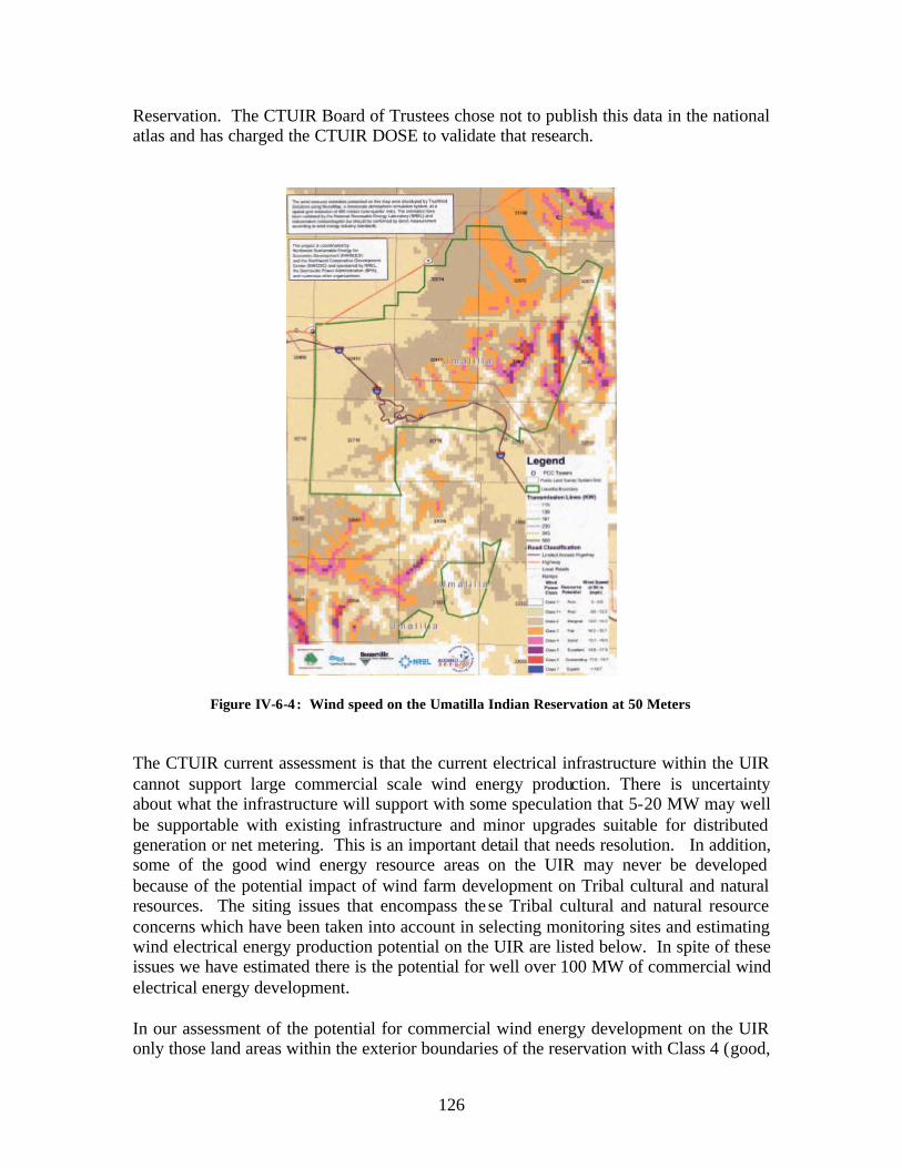
Reservation. The CTUIR Board of Trustees chose not to publish this data in the national atlas and has charged the CTUIR DOSE to validate that research.
Figure IV-6-4 : Wind speed on the Umatilla Indian Reservation at 50 Meters
The CTUIR current assessment is that the current electrical infrastructure within the UIR cannot support large commercial scale wind energy production. There is uncertainty about what the infrastructure will support with some speculation that 5-20 MW may well be supportable with existing infrastructure and minor upgrades suitable for distributed generation or net metering. This is an important detail that needs resolution. In addition, some of the good wind energy resource areas on the UIR may never be developed because of the potential impact of wind farm development on Tribal cultural and natural resources. The siting issues that encompass the se Tribal cultural and natural resource concerns which have been taken into account in selecting monitoring sites and estimating wind electrical energy production potential on the UIR are listed below. In spite of these issues we have estimated there is the potential for well over 100 MW of commercial wind electrical energy development.
In our assessment of the potential for commercial wind energy development on the UIR only those land areas within the exterior boundaries of the reservation with Class 4 (good,
126

15.7-16.8 mph @ 50m) or better wind were considered, although Class three areas have also been considered for potential development in other areas. The CTUIR intends to validate the projected data for the whole reservation starting with the locations with the strongest wind resource and development potential. Although the models are considered excellent references, validation is very important as the models are models and not reality. Furthermore, a substantial portion of the high potential areas contain complex terrain, which are more difficult to model. Several areas on the Umatilla Indian Reservation show high potential for wind energy development and have been prioritized for direct assessment.
Some of the potential wind resource areas are not near transmission lines, impact wildlife habitat, or are at known cultural resources sites. Much of the wind potential is on Cabbage Hill and associated ridges above 2000 feet in elevation. This includes big game winter range; this includes root gathering and hunting areas utilized by the tribes since time immemorial. These issues do not prevent the CTUIR from investigating wind potential but they will be factors and in these areas. CTUIR conditional use permits are required for all scientific research. Currently only investigative endeavors are allowed by permit, actual wind development would require amendment to the CTUIR Land Use Planning Code.
IV-6-5-2. Anemometer Siting Criteria
The CTUIR’s Department of Science and Engineering working with other Tribal programs developed anemometer siting criteria with fourteen criteria to be considered. These are not prioritized except for the presence of wind. The anemometer siting criteria have also taken into consideration, the next step beyond gathering wind energy data for the UIR, i.e., commercial development, distributed generation.
1) Wind – The current DOE wind energy map will be used to help evaluate the most likely locations to find this resource.
2) Elevation – Generally the higher the elevation the greater the wind resources. In addition, the foothills of the Blue Mountains commonly have periodic winter time inversions. Siting above this stagnant air will be important in achieving a good turbine capacity factor. Elevation will also affect wind density
3) Transmission – what is the proximity of the transmission lines to the wind resource. Also what are those transmission lines capable of carrying and existing commitments?
4) Accessibility – Does the CTUIR own access to the area/site? And how easy will it be to install anemometers, gather data, and provide repairs and maintenance?
5) Visibility- Although more relevant to wind power towers would wind development cause visibility issues?
127

6) Wildlife and Fisheries- What species are present and possible impacts of anemometers on habitat? Further on, what would be the impact of wind turbines and the wind farm with supporting infrastructure on species and habitat? An avian survey would be required.
7) Cultural Resources – Cultural Resources Inventories are required to identify potential impacts of ground disturbing activities on known or potentially unknown cultural resources.
8) Ownership- Not only does the CTUIR own interests but whom else has interest in lands potentially affected by investigation or access to instruments.
9) Topography – The shape of the landscape has a direct influence on wind including affecting turbulence and channeling wind.
10) Aspect – The towers should be sited where they will capture predominate wind characteristics during the majority of the year. As an example, an east west trending ridge may capture more wind then a north south trending ridge (or vice versa).
11) Vegetation - Plants are often an indicator of wind and can also have an impact on wind such as trees causing turbulence.
12) Economics - Of scale and costs. Although developing these criteria are designed to ultimately identify project and minimize costs economic realities also drive project development.
13) Strategic placement of regional survey-Anemometers will be placed to verify regional wind map and to determine metrological, and climate data reservation wide.
14) End User- This will determine the size of the project. Will the project be for commercial or residential use? Who will purchase and use the power?
Visibility
Currently the CTUIR has one major known visibility issue. During the development of the Tamástslikt Cultural Institute the view shed of Cabbage Hill and the Umatilla River Canyon are built into the design of the interpretive center as part of the experience. Some of the areas where good wind energy is known are within the view of the Wildhorse Resort. It is intended to use the anemometer experience to further the community’s conversation about wind development and identify all potential impacts.
Cultural Resources
All wind projects on Cabbage Hill or the ridges extending from the western slopes of the Blue Mountains would impact known cultural resources and wildlife habitat such as root fields, hunting areas, and Big Game winter range. Site specific surveys will ensure
128

protection of archaeological sites however the potential impact to traditional use areas would need to occur.
Wildlife
Technology has improved over time making wind towers and wind turbines safer for wildlife especially for avian and bat species. Appropriate avian and wildlife studies would need to be conducted. Another main concern identified would be the impacts of transmission lines and infrastructure on wildlife. Again appropriate research and surveys would be necessary to assess potential impacts.
Land Ownership
Land ownership on the Umatilla Indian Reservation like many reservations is complex. Land ownership is fractionated and checker boarded due to the Slater and later the Dawes Allotment Acts in which non Indians own lands on the Umatilla Indian Reservation. Further due to limited land availability many Tribal allotments are owned by many different Tribal members ranging from one owner to over forty owners. The Tribe does own full interest in some lands and some lands are in trust however these are not necessarily where the wind resource is located. All land owners in areas where the wind model shows the highest potential have been identified. Land ownership is identified as allotments and Trust lands managed by the BIA, Tribal Fee managed by the CTUIR and Fee lands owned by non Indians. Each have slightly different regulatory processes and drivers.
IV-6-5-3. Infrastructure
Infrastructure related to wind is also a major issue. Although we have two utilities Umatilla Electric Cooperative and Pacific Power as well as the Bonneville Power Administration with distribution and transmission lines crossing and serving the reservation these lines are purported as being at capacity, are aging, and may not be close to the most desirable wind resource locations. Lines to substations and transformers would be required to accommodate the electrical engineering requirements of a commercial wind farm. These factors add significantly to the costs of wind development.
Currently the primary transmission line that crosses the reservation is a BPA 230 kV line from McNary to Brownlee. An upgrade of this line is estimated to cost $600,000 per mile. There is another BPA line that runs parallel to the one through the UIR through Walla Walla that hub at the McNary substation. This line is further from the Reservation and would require the CTUIR to construct a low voltage line of 66 kV or less to deliver power from the wind farm.
Even so the CTUIR DOSE is responsible to validate the wind map. The DOSE has developed a systematic strategy to begin the process of gathering data to test the current wind development maps. Using the anemometer siting criteria has allowed the DOSE to
129

systematically prioritize locations where to erect reference towers and supporting instrumentation. Land ownership and control perhaps being the most decisive criteria.
IV-6-6. Wind Monitoring Feasibility
Potential wind energy areas are identified on the map. The DOSE has first concentrated on areas with class 4 or better wind speed combined with the other 13 siting criteria to identify potential monitoring sites. The DOSE did perform several reconnaissance field trips on the reservation for monitoring site selection where GPS location and other information was gathered. These areas were compared with land ownership maps. All selected monitoring sites are owned by multiple tribal member land owners.
To simplify research the reservation was divided into study areas. Each study area will ultimately have a meteorological reference tower and satellite towers. Study areas include the North Reservation, Umatilla River, Cabbage Hill, The Wildhorse Resort, Squaw Creek Southeast, Tutuilla flats, South reservation and two off reservation locations Wanaket and Rainwater Ranch. Tutuilla Flats and South Reservation are modeled to only have minimal potential however they will be investigated in the future. A strategy for monitoring the off reservation sites has yet to be developed.
The need for reference towers goes beyond that for wind monitoring to include research purposes related to atmospheric monitoring, open burning and smoke management and visibility issues related to air quality and EPA work on the UIR. Some sites may be able to meet multiple purpose use, thus extending limited resources.
IV-6-6-1. Study Areas The study areas for wind energy development are listed below as well as shown in Figure IV-6-5 and in more detail through IV-6-9
1) North Reservation Township 3North Range 34East Sections: 1,2, 11,12,13,14 Township 3North Range 35East Sections: 5, 6, 7,8,9,10,11, 13, 14, 15, 16, 17, 18, 19, 20, 21, 22, 23
2) Umatilla River Township 3 North Range 34 East Sections: 33, 34, 35, 36 Township 3 North Range 35 East Sections: 29, 30, 31, 32
3) Cabbage Hill Township 2North Range 34East Sections: 33,34,35,36 Township 2North Range 35East Sections: 31,32,33,34. Township 1North Range 34East Sections: 1,2,3,4,5 Township 1North Range 35East Sections: 5,6
4) Squaw Creek SoutheastTownship 1 North Range 35 East Sections: 1,2,3,11,10
5) Wildhorse Resort (meteorological, air quality, and scientific research platform planned
130

6) Tutuilla Flats (future research)
7) South Reservation (future research)
Off reservation
8) Wanapa/Wanaket, McNary, Oregon – The CTUIR own a trust allotment in a 195 acre parcel net to the Port of Umatilla Industrial Park. This land is part of the Wanapa energy Center along the Columbia River. It is in close proximity to Ninemile Canyon, WA and the OR/WA Stateline Project but is not located at such favorable elevation. There is CTUIR interest in assessing wind at this site. There is also possibility for distributed generation to the Port of Umatilla industrial park and state of Oregon correctional Facilities.
9) Rainwater Ranch, Dayton, WA - This is a 8441 acres restored for wildlife Habitat that includes, timber, rangeland, eight miles of spawning habitat in Columbia County, Washington along the front hills of the Blue Mountains similar to the Umatilla Indian Reservation. There are suspected class 3 and 4 winds at this location It is unknown at this time whether wind could be developed here and used to benefit or consistent with wildlife conservation or that the CTUIR would like to pursue it.
In Squaw Creek southeast there are no Trust allotments along the ridge top. Here there is good wind and potential access to transmission. A site will need to be determined and land owners will have to be contacted prior to selecting a reference tower location in this vicinity.
Three meteorological reference tower locations on the Umatilla Indian Reservation were identified as primary reference locations. All of these areas have approximate class four or better wind speeds. The primary criterion was the projected presence of wind. The secondary consideration for selecting these locations was CTUIR controlled ownership. The CTUIR land use code allows for conditional use permits for scientific research. Meteorological reference towers may serve other environmental monitoring uses and may be installed and utilized for longer time periods and for other scientific research.
Reference Tower locations
1) North Reservation: North of the Umatilla River in along the south west edges of Reservation Mountain at approximately 2100‘ MSL, Communications Tower Township 1North, Range 34 East, Sec. 2 Predominately Agricultural area with trust and tribal allotments.
131

2) Umatilla River. North of the Umatilla River at T3N R34 East Sec 35. Elevation, ranges between 1800 and 2400 feet MSL. It is unknown if this area is under the same inversion layers like the deeper valleys. This area is predominately agricultural with trust allotments.
3) Cabbage Hill: South of the Umatilla River on the top of Cabbage Hill above 3800’ MSL in elevation. Township 3North, Range 35 East, Section 17. Emergency operations tower will serve as reference tower which will serve as a research hub to investigate Kanine and Telephone ridges.
4) Squaw Creek: South East of Squaw Creek Overlook. At this time no land within exclusive tribal control for a reference tower has been identified. This area would also serve as research hub for Gibbon Ridge.
In addition to these reference locations the DOSE using the regional wind map as a guide has identified supplementary suitable locations for additional anemometers and additional spatial analysis within areas of interests. Most of these are owned by multiple Tribal members. The selected allotments listed do not represent a complete list of allotments but those where it is scientifically desirable and where access may be secured to erect anemometers.
132

Specific land owner information is available at the CTUIR. There is also considerable non-Indian ownership in the vicinity of some of the study areas. This is especially true of land ownership in the northern reservation where there is more extensive agriculture than the other areas.
IV-6-6-2. Wind Monitoring Strategy
During the feasibility phases it was clearly identified that we will need wind measuring instruments as such the DOSE began to explore anemometer loan programs. Fortunately a 50 meter tower with an NRG system previously used at the Whidbey Island Naval base was identified by BPA and loaned to the CTUIR. The CTUIR has recently erected a 180 foot communication tower on top of Cabbage Hill located at 1North, 34 East in Section 2. These two towers will be used as long term reference towers in which the CTUIR will put wind instruments at three different on each tower. The communication tower is immobile and will be a permanent wind reference point. The fifty meter NRG system tower will be erected on the northern reservation area on Trust land located at 3North, 35 East in section 17. These reference towers will provide wind speed and direction, temperature, barometric pressure, vertical wind speed, and precipitation.
The DOSE plan is to acquire smaller towers through loan programs to gather supplemental data to identify the best locations for wind tower micro siting and continued wind analysis with goal of identifying possible wind tower sites where hub height anemometers will need to be installed and validation of wind energy map.
Instruments need to be checked and calibrated prior to operation. A Quality Assurance and Quality Control plan will be developed to ensure that data is gathered and managed properly. Data will be gathered at each site using data loggers. The anemometer data will be routinely collected from the monitoring instruments and analyzed by DOSE personnel. Monitoring and data process will follow the QA/QC Plan and validated by an experience meteorologist or other properly trained individual. Data will be reported to partners in the project and NREL but at this time the CTUIR does not wish Umatilla Indian Reservation Data to be put into the public domain.
Data analysis will consist of both meteorological as well as energy potential analysis. Data will consist of descriptive information and maps, correlations of data to known turbine dimensions, engineering characteristics, and layouts, relevant power curves. Data analysis will also include correlation of data from smaller towers with data provided from the long term reference sites. Such information should help us to assess the seasonal, diurnal, turbulence, spatial variations of wind characteristics, wind shear analysis, and information to project long term wind characteristics.
The two initially selected study areas are believed to provide the best opportunities for anemometer siting and potential also for economic development.
133
The North Reservation site is more removed from transmission but is located in agricultural lands with deep soils. The north reservation is the southern extent of the Palouse soil formation created as the result of ice age floods. The soil units are described as being Palouse silt loam on 1-7 percent slopes. This will need to be considered when determining how to anchor meteorological towers. If the wind energy is determined viable, transmission, transformers, inter-ties, and other engineering improvement would be required. Major upgrades to tie into existing substations and new transmission are needed. Underground transmission could be developed to tie in with the UEC Mission substation. This would require approximately 15-20 miles of transmission.
Cabbage Hill and associated ridges are located near the largest transmission line currently available. The landscape is characterized by shallow soils above basalt and is designated as big game winter range. This area does have forested areas consisting of lodge pole pine, ponderosa, pine and mixed conifer. Anemometers would be sited within “scab” meadows along the ridges. These meadows are extensively utilized by the Tribe for root and other plant procurement. These shallow soils and basalt bedrock will need to be considered prior to erecting meteorological stations. If the resources are determined viable for economic development transmission line, transformers, inter-ties and other engineering improvements would be necessary. Transmission of approximately 9-12 miles to the BPA Round-up Substation (T2N R32E Sec. 18) on the Goad Road or the UEC Mission Substation (T. 2N, R33E, Sec. 4) may be necessary. Other alternatives will be explored in due course of CTUIR renewable energy development effort.
IV-6-6. Conclusions and Recommendations
The Confederated Tribes of the Umatilla Indian Reservation has a viable wind resource that has not been fully quantified. In addition there are transmissio n and distribution challenges that would need addressed prior to or as part of any wind project development. Some of the CTUIR’s wind resources is located in areas with cultural or natural resources significance. Although wind is accepted and promoted by the CTUIR it is unknown with such preliminary information whether General Council would support such an endeavor on the reservation or where on the reservation. It is suggested that the CTUIR BOT adopt policy supporting the research and development of renewable resources on the Umatilla Indian Reservation. There fore the following technical actions are recommended to gather the information necessary to make an informed decision.
• The CTUIR DOSE continues to move forward to validate the wind map and assess wind speeds and power potential on the reservation looking at potential for both distributed generation and/or commercial potential.
• The CTUIR DOSE completes the CTUIR land use planning conditional use permit applications for selected meteorological sites and begin discussions with the bureau of Indian Affairs for sites under their jurisdiction..
• That the CTUIR DOSE coordinate with the CTUIR Department of Natural Resources and Department of Economic Development in developing proposals to gather all appropriate data relevant to environmental conditions, natural resources, cultural resources, and economics
134

Outside the realm of this study the CTUIR should consider other options for CTUIR investments in wind energy that should be examined include:
• Purchasing wind power directly from PacifiCorp through “Blue Sky” program as available
• Investing in other Tribal wind projects • Investing in additional non Indian wind developments
135

IV-6-7. References
American Wind Energy Association, Wind Energy Fact Sheet “Wind Energy and Birds.”
American Wind Energy Association, Wind Energy Fact Sheet “Facts about Wind Energy and Noise.”
Bonneville Power Administration, 2004 Annual Report.
Columbia River Inter Tribal Fish Commission, 2001“Draft” Energy Vision for the Columbia River, Prepared by Tom Foley consultants and the CRITFC, Portland Oregon.
Federal Energy Technology Center, 1999 Distributed Degeneration: Securing America’s Future with Reliable Flexible Power, USDOE Office of Fossil Energy, Federal Technology Center.
Green Power Marketing Group, n.d. Internet Home Page Wind Energy Overview. On file CTUIR.
Harvest Land Cooperative, 2002 Wind Power Electrical Generation in a Cooperative System, Grant application submitted to the USDA Rural Development program.
Johnson, Jeff, “Blowing Green,” Chemical and Engineering News, Alternative Energy Section, February 24 2003.
Kolstrud, David, Locally Owned Energy Projects “From Conception to Completion” Steps involved. Presentation prepared for Harvesting Clean Energy 4th Annual Conference.
Oregon Office of Energy, 2003, Oregon Wind Working Groups Action Plan for Achieving Its Strategic Objectives.
Oregon Administrative Rules, OAR 330 -090-0105 to 330-090-0150 (for ORS 469.185; 315.354; 315.356.
Schienbein, La wrence, 2004, Transmission Access for Wind-generated Electricity, DOE funded Technology Assistance Agreement: 04-37 CTUIR.
USDOE NREL, Wind Energy Resource Map, May, 2001, U.S. Department of Energy, National Renewable Energy Laboratory
Union of Concerned Scientists, Fact Sheet, “Farming the Wind: Wind Power and Agriculture.
United Stated Department of Interior BIA, 2004, Wanapa Energy Center Final Environmental Impact Statement
USDA Soil Conservation Service, 1985 Soil Survey of Umatilla County Area, Oregon.
USDOE, 2001, Small Wind Electric Systems, A U.S. Consumers Guide, DOE/GO -102001-1293. USDOE NREL.
2002, Wind Power for Municipal Utilities. Wind and Hydropower Technologies Program. Office of Energy Efficiency and Renewable Energy.
Renewable Northwest Project, 2002(rev),Wind Power Fact Sheet
136

Klickitat County Wind Energy Resource Assessment, Klickitat County Energy Overlay Environmental Impact Statement.
Energy Northwest, 2003 Energy Northwest Power Project Development Presentation
Energy Northwest, 2003 Fact Sheet, “Renewable Energy and Environmental Programs
Nelson, Vaughn, “Wind Energy and Wind Turbines,” Alternative Energy Institue, West Texas A&M University, Canyon, TX 79016.
137

Final Report DOE-Funded Technology Assistance - Agreement: 04-37 Confederated Tribes of the Umatilla Indian Reservation (CTUIR) Task Title: Transmission System Access for Wind-generated Electricity
Prepared by: Lawrence Schienbein, Ph.D. Staff Engineer Pacific Northwest National Laboratory
Following is the activities statement from the Agreement document:
PNNL is to “provide advice about access to, and capacity limitations of, the electrical transmission system on the Umatilla Indian Reservation.”
1.0 Present Transmission System Lines
The primary transmission access line that crosses the Reservation is Bonneville Power Administration (BPA) line B (1). This is a 230 kV line. BPA's publicly available planning information identifies it as being part of the proposed "Pacific Northwest - Idaho Reinforcement Phase II (McNary-Brownlee). However, the best information that we have is that BPA cannot fully fund the project (about 160 miles of new 230 kV line that would effectively double the capacity) and that it is seeking third-party financial participation. BPA postponed the project indefinitely until third party financing can be arranged.
Transmission line B (5), which runs parallel to B (1), connects indirectly to the McNary hub (requir ing use of the existing transmission line from Walla Walla to McNary) and may be an option for delivering wind power generated electricity. However it is farther from the high wind ridges, as we understand the locations, and would require that CTUIR construct a much longer lower voltage line (66 kV or less) to deliver power from the wind farm to a substation where it connects to the BPA transmission line. (See also Section 2.0.)
The McNary - John Day reinforcement proposed by BPA, which we believe is essential for delivering power from the CTUIR wind power project to customers on the West Coast, is also officially on hold. BPA is seeking private financing for that upgrade.
The latest cost estimate for the McNary-Brownlee upgrade is about $95 million for 160 miles, or about $600,000 per mile ($6000/MW-mile). If the CTUIR were to construct an approximately 40 mile segment of the 230 KV upgrade from the Reservation wind farm’s substation to McNary, the cost would be about $25 million. The capacity of this upgrade would be about 200 MW, possibly 250 MW. Therefore, in principle, about 100 to 150 MW of capacity would be available to lease to third parties, should the CTUIR’s needs for wind power be limited to 100 MW.
Based on a wind farm “all up” project cost of about $100 million for 100 MW wind farm and, if the wind resource tapped by the wind farm is well above average (“exceptional” - perhaps a capacity factor approaching 0.4) as there is some reason to believe, the additional $25 million investment in the transmission line to McNary may still make the project feasible. The very recent reinstatement by Congress of the federal production tax credit (currently $0.018/kWh), which runs for 10 years for approved projects, certainly encourages pursuing the CTUIR wind farm if the CTUIR or a third party group that may finance and own the wind farm (depending on how CTUIR structures the deal) can qualify.
138

The cost and implementation of the McNary-John Day reinforcement is more problematic. Our latest information indicates that the estimated cost for this 500 kV proposed upgrade is about $170 million. Based on 80 miles of line and an estimated capacity of 1250 MW, the cost is about $1700/MW-mile. While certainly a lot less costly in these terms than the lower voltage line discussed previously, the CTUIR would only require 100 MW of this capacity, based on our best information. Furthermore, as previously stated, this upgrade could not move forward without partners prepared to pick up the remaining costs. Assuming that a partnership could be put together, the CTUIR portion, based on simply prorating the capacity, would be $13.6 million.
Again , this adder to the project cost may not kill the 100 MW power plant project economics. In simple terms, the total adder for transmission upgrades to bring the CTUIR wind farm’s power to the “West Side” and California power markets would be about $40 million (or about 30% of the total costs associated with the 100 MW wind farm). A part of that cost could be offset by selling capacity access (possibly to BPA?) for a large part of the 40 mile 230 kV McNary upgrade segment discussed above. Whether and when that would be possible is very much guesswork at this stage.
On the other hand, the cost of the transmission upgrades supports a hard look at a much larger wind power installation on the CTUIR lands to take advantage of the economies of scale inherent in the wind farm itself and the transmission upgrades. For example, the transmission upgrade part of the cost could shrink to only about 20% of the total cost if the wind farm peak capacity could be increased to 250 MW ($250 million, or possibly less) for the wind farm and power collection system. $25 million additional would be required for the 230 kV upgrade from the wind farm to McNary and $34 million for the CTUIR portion of the McNary-John Day reinforcement.
Very recent public information from BPA (November 2004 Newsletter) concerning five new wind farms in Oregon and Washington is appended. The statements in the third and last paragraph concerning available transmission capacity have been underlined, as they are of particular relevance.
2.0 On-Site Lower Voltage Power Transmission and Substation Requirements
A utility scale wind power plant constructed on the CTUIR Reservation will require that one or more, lower voltage transmission lines (wind farm power “collector” lines, so to speak) be constructed to connect the wind farm to the existing BPA transmission line(s). These would typically be overhead lines, to minimize cost. In addition, one or more CTUIR-provided voltage step-up and power switching substations will need to be constructed where the “collector” lines meet the BPA high voltage transmission system. The “collector” lines would typically be at a voltage of 66 kV or less.
In order to provide the CTUIR with estimates of the cost of these lines and the substations, and to minimize their cost, it would be highly beneficial to know the currently proposed specific locations of wind turbine groups. For example, if the wind farm is made up of several fairly widely dispersed turbine clusters, there would be a need for several collector lines and possible several substations. In addition, under that scenario, several connections might be required to both BPA transmission lines that cross and are near to the Reservation. That work would be part of the project feasibility study that would also include, but not be limited to, the wind resource
139

assessment, environmental assessment, proposed turbine micrositing and output estimates, access roads, construction logistics, turbine size selection and so on.
3.0 Notes on Assumptions, Conclusions and Further Work
All of the preceding estimates are very approximate and based on the best information that we have and constrained by the limited resources available to fund our work on this task.
Also, as we have discussed, PNNL, because of its status as a National Laboratory, cannot provide independent opinions concerning the reports, conclusions, consultant opinions and other information that the CTUIR may have or have had access to regarding current BPA transmission capacity and capacity constraints that bear directly on the CTUIR’s interest in wind farm development and delivering wind generated electric power to customers. We would be pleased, however, to approach BPA with the objective of obtaining their full and favorable cooperation in reviewing, discussing and assessing relevant transmission line loads and possible constraints. We believe that this could be highly beneficial to the CTUIR’s interest in developing the wind farm. For example a detailed “time of day” and seasonal transmission line loading analysis done in conjunction with forecast “time of day” (on a 365 day a year basis) power delivery from the wind farm may show that the transmission line upgrade capacity requirements could be greatly reduced. This capacity assessment work would require a separate contract.
As we have discussed, PNNL is well equipped to assist the CTUIR in moving forward with its current wind power plant project feasibility assessment. Furthermore we can provide significant expert independent support to the CTUIR as planning, engineering, financing, construction and commissioning materialize. Our discussions to date have included the various specific areas where either PNNL (or Battelle Pacific Northwest Division, as appropriate) can provide support to the CTUIR. As previously stated, we would be very pleased to provide further specifics and to meet with CTUIR staff and the Board of Trustees on that subject and on the results of the work reported here.
140
Appendix A
Regional Update on Wind Energy in the Pacific Northwest By Bonneville Power Administration
November 2004 Newsletter
Here in the Northwest as much as 800 megawatts of new wind-generated energy could hit the region's electrical gr id by the end of 2005. Steve Enyeart, TBL customer service engineer, says, "Planning, environment, design and construction may be faced with some interesting challenges in the coming months if we are going to meet the schedules proposed by the developers wanting to take advantage of the tax credit."
Enyeart said that the 800 MW could come from five new wind farms in Oregon and Washington that are nearly ready to go. That could mean $500 million to $900 million in new investment in the region.
To interconnect those five, BPA must build three new substations, all funded by the wind developers. "In order to meet developers' schedules, we have to begin building those substations by next March and complete them by November," Enyeart said. He estimated that could add up to $20 million worth of work for BPA. Another developer has recently suggested BPA rebuild 14 miles of the Goshen-Palisades transmission line in Idaho to connect a proposed wind plant near Idaho Falls to PacifiCorp's system.
"All these projects mean close coordination with our environmental staff," said Rick Yarde, environmental protection specialist. "We're working with TBL to streamline schedules and focus our environmental studies on the impacts of those proposed interconnections." One way of streamlining is by doing facilities designs and environmental studies simultaneously rather than sequentially.
Yarde says the sudden crush of work will be challenging as wind developers revive proposals that have been lingering in the request queue. "Even if BPA has no money or construction involved, we still have to study the impacts of an interconnection," Yarde said.
In the Power Business Line, customer account executive Debra Malin foresees an increasing number of requests for network wind integration service and storage and shaping services, but she says, "We're ready for such requests."
Most of the interconnection studies are nearly complete, and environmental studies for the five Northwest projects are underway. However, there are still transmission capacity and operational issues. Enyeart says there is no available transmission capacity to sell in most of the corridors serving the new wind plants. "Nearly all these new projects will initially depend on nonfirm transmission to get their power to market," he said. Even with the successful completion of the proposed McNary-John Day 500-kilovolt transmission line, additional firm transmission wouldn't be available in the primary corridor until Spring 2007 at the earliest.
141

DRAFTDRAFTDRAFTDRAFTDRAFTDRAFTDRAFTDRAFT
V. Renewable Energy Vision
A White Paper
Prepared by:Confederated Tribes of the Umatilla Indian Reservation
Department of Science & Engineering
June 9, 2005
Energy, just as air, water and food is an essential natural resource. All these resources are connected and interdependent. All living things depend upon some form of energy for survival. Our sun is believed to be the primary source of most of this energy. Without the sun warming the earth, it’s temperature would be continuously below -100 oF, which would make life as we know it impossible. Plants also depend upon the light energy from the sun to perform photosynthesis, to live, and grow and reproduce. For the most part, other livings things depend upon the plants for food and the oxygen they produce. The sun causes the wind to blow and moves water from the oceans to the mountains to fill the streams which are used among many other things to produce electricity. It is estimated that the sun has been providing 1.42E21 calories per day (5.64E18 Btu/da; 6.89E10 MW) of power to the earth surface for the last few billion years. A vast amount of this energy (power x time) has been stored in the chemical compounds in plants, animals, trees, coal, petroleum, oil shale and natural gas. These forms of the sun’s supplied energy in conjunction with modern technology used to discover, recover, transpose and transport it to users in suitable forms allows us to heat and light our homes, cook our foods, power our automobiles, trucks, trains and planes, produce and transport electricity, run our industries and businesses and much more. Clearly, things would not be the same without abundant, reliable and reasonably inexpensive forms of energy. It is this energy that fueled the industrial revolution and in our opinion is a key ingredient to being a powerful nation.
The renewable energy vision for the Confederated Tribes of the Umatilla Indian Reservation (CTUIR) is one that seeks a balance with natural and cultural resources. An energy vision that meets the energy needs of the community, that is sustainable and consistent with the cultural values and ancestral teachings of the tribe. The CTUIR way of life has been intimately entwined with the once abundant natural resources of the Columbia River Plateau. This ancient lifestyle relied on moving in tune to the natural seasonal availability of gifts from the creator. Respect for the environment was paramount, to not take without giving, to not use and abuse to consider the holistic impact of contemporary actions to future generations. A lifestyle based on conducting our life in a respectful, sustainable manner, walking lightly on the earth.
142
Many businesses and energy technologies of today do not hold this as a primary guiding philosophy and it is evident in the United States energy infrastructure. The CTUIR have suffered tremendously from the impact of the regions hydroelectric system on natural and cultural resources. Most of our current energy utilization technologies are leaving a large footprint and are not sustainable as practiced. Estimates are provided that the fossil fuels (coal, oil and natural gas) which provide the backbone of the nation’s energy will not be able to keep-up with demands in the next 20-50 years. The large environmental insult from their utilization has left essentially all of the air, water, land and foods contaminated with their byproducts. In some cases too, well recognized human health impact levels associated with food contamination is known which has been linked to energy using technologies, i.e., mercury in fish. Renewable energy can assist in balancing, reducing, and conserving our fossil fuel consumption, reducing pollution, saving water, and improving the communities quality of life.
The CTUIR shall work to provide lowest practical environmental impact, reliable and sustainable forms of affordable energy options for its people. Community energy sustainability and energy independence is a matter of sovereignty. With the eminent loss of fossil fuels in this century it is essential that the CTUIR be directly involved in the development of the new energy economy. It is equally important that the CTUIR understand itself as an energy entity and seek to develop a diverse portfolio of energy sources. The CTUIR needs to be intimately involved in the reshaping and redesign of the regions energy infrastructure and ensure that a more equitable balance between energy production and consumption with natural and cultural resources. Energy consumption and use will be forced to change. The CTUIR needs to be proactively involved in keeping in step with changes and making well planned investments ahead of the changing energy curve.
Some Energy Considerations and First Steps.
CTUIR shall develop an over all energy policy. This policy should include provisions that plan and strategize to move from an energy customer to energy independence where it secures and supplies its energy in the forms compatible with culture and community values and in forms with the least environmental impact to air, water, land and food. This plan recognizes the long-term need for moving from an essentially fossil based energy production and consumption organization, to improving efficacy, conserving energy, and utilizing renewable and sustainable energy sources. In concert with this effort the CTUIR will be developing energy capabilities so that it has the staff to effectively plan, manage and operate its energy program. The CTUIR will promote, practice and demonstrate that diverse renewable sources of energy are good for us all. As an initial effort the CTUIR will seek 20% of its energy from renewable sources.
In as much as energy is an essential and powerful natural resource, integral to the circle of life, the CTUIR will factor energy into all its policy and decision making activities. As an example, when land acquisitions are being contemplated, consideration should be given to what energy needs, energy potential and energy resources the land possess. Does the land have wind, sola r, geothermal, hydro, or other energy resources? In the
143
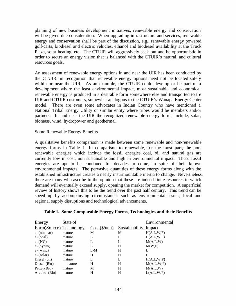
planning of new business development initiatives, renewable energy and conservation will be given due consideration. When upgrading infrastructure and services, renewable energy and conservation sha ll be part of the discussion, e.g., renewable energy powered golf-carts, biodiesel and electric vehicles, ethanol and biodiesel availability at the Truck Plaza, solar heating, etc. The CTUIR will aggressively seek-out and be opportunistic in order to secure an energy vision that is balanced with the CTUIR’s natural, and cultural resources goals.
An assessment of renewable energy options in and near the UIR has been conducted by the CTUIR, in recognition that renewable energy options need not be located solely within or near the UIR. As an example, the CTUIR could develop or be part of a development where the least environmental impact, most sustainable and economical renewable energy is produced in a desirable form somewhere else and transported to the UIR and CTUIR customers, somewhat analogous to the CTUIR’s Wanapa Energy Center model. There are even some advocates in Indian Country who have mentioned a National Tribal Energy Utility or similar entity where tribes would be members and/or partners. In and near the UIR the recognized renewable energy forms include, solar, biomass, wind, hydropower and geothermal.
Some Renewable Energy Benefits
A qualitative benefits comparison is made between some renewable and non-renewable energy forms in Table I. In comparison to renewable, for the most part, the nonrenewable energies which include the fossil energies coal, oil and natural gas are currently low in cost, non sustainable and high in environmental impact. These fossil energies are apt to be continued for decades to come, in spite of their known environmental impacts. The pervasive quantities of these energy forms along with the established infrastructure creates a nearly insurmountable inertia to change. Nevertheless, there are many who ascribe to the opinion that these are indeed finite resources in which demand will eventually exceed supply, opening the market for competition. A superficial review of history shows this to be the trend over the past half century. This trend can be speed up by accompanying circumstances such as environmental issues, local and regional supply disruptions and technological advancements.
Table I. Some Comparable Energy Forms, Technologies and their Benefits
Energy State of Environmental Form(Source) Technology Cost ($/unit) Sustainability Impact e- (nuclear) mature M M H(A,L,W,F) e (coal) mature L L H(A,L,W,F) e (NG) mature L L M(A,L,W) e (hydro) mature L H M(W,F) e (wind) mature L-M H L e (solar) mature H H L Diesel (oil) mature L L H(A,L,W,F) Diesel (Bio ) immature H H M(A,L,W,F) Pellet (Bio) mature M H M(A,L,W) Alcohol (Bio) mature H H L(A,L,W,F)
144

Alcohol (NG) mature M L H(A,L,W,F) Heat (solar) mature M H L Hydrogen (NG) mature M L H(A,L,W,F) Hydorgen (Bio) mature H H M Hydrogen(hydro) mature H H M
L- low, M-medium, H-high, A-air, L- land, W-water, F-food, e—electricity, NG-natural gas, Bio-biomass.
145

VI. Business Development Planning
The business plan for each of the renewable energy sources investigated in this study, wind, solar, and biomass is discussed below while a schedule that estimates the timing for their development is shown in Table II at the end of this section.
VI-1. Wind Energy Business Plan
The wind energy business plan consists of capabilities development, wind monitoring and staged commercial development. An estimate of the time schedule for these elements of the plan is shown in Table II at the end of this section. The plan recognizes there are a number of essential elements and ways to go about developing wind energy including the following which in themselves may not be sufficient to secure the necessary funding.
1. A multi year high-quality wind resource assessment that includes at least one year of monitoring data in potential commercial wind production areas.
2. A long-term lease or easement agreement with the landowner 3. A land use permit and/or conditional use permits, if required, from the CTUIR,
local, state, or federal agencies 4. An interconnection and wheeling agreement with the local transmission or
distribution provider5. A power purchase agreement with a creditworthy buyer.
The wind energy business plan recognizes and addresses these elements as described below including developing partnerships to jump-start the program while we continue to build internal capabilities and secure the necessary on reservation wind monitoring data. The immediate goal is to develop sufficient wind energy capacity to make the CTUIR electrical energy independent. Wind is a natural resource that can be developed to bolster economic growth and stability for the CTUIR as well as provide jobs.
IV-1-1. Capabilities Development
The capabilities development has begun with this feasibility study. Staff have attended a number of wind energy workshops, training sessions, becoming familiar with the technology and economics of wind energy development. Further capabilities will be gained as the CTUIR renewable energy program matures and wind energy projects are undertaken by the CTUIR.
IV-1-2. Wind Monitoring
CTUIR staff have considerable meteorological monitoring experience and wind monitoring training. The CTUIR has planned to undertake a multiple year wind monitoring effort on the Umatilla Indian Reservation to map the CTUIR’s wind energy resources, verify existing wind energy maps, an locate areas of the UIR with the best commercial wind development potential. The planned monitoring effort seeks to
146
implement the result and recommendations of this assessment and feasibility study. Support for the monitoring effort is anticipated to be secured through government grants, anemometer loan programs, and Tribal funding.
IV-1-3. Staged Commercial Wind Development
The plan is to undertake staged development approach for wind electrical generation. Capacity will be built over a several year effort as shown in the schedule in Table II. The components of the staged development plan include explore partnerships, self-sufficiency (3 MW), 10-fold scale increase to 30 MW, and 60 MW farm. This feasibility assessment has indicated that the Umatilla Indian Reservation has over 150 MW wind energy development potential from good and better wind energy fields so the upper limit on commercial wind development may be far greater than planned at this time.
The CTUIR has met with a number of wind energy developers regarding partnerships and these opportunities will continue to be actively pursued and investigated. One outcome of these meetings has been the formation of a joint venture with Columbia Energy Partners in the 104 MW wind energy development project near Arlington, Oregon. The Arlington wind energy project is off the UIR, which underscores the ability of the CTUIR to enter into wind energy development nearly anywhere in the world. Hence, if the wind potential on the UIR does not prove out or other obstacles impede wind development such as lack of transmission capacity, the CTUIR can look elsewhere to engage in wind energy development until local conditions are favorable for development on the UIR. The joint venture with Columbia Energy Partners effectively jump-starts CTUIR’s effort to develop renewable energy sources.
VI-2. Bio-Pellet Fuel Business Plan
A biomass pellet fuel manufacturing facility will be located at the CTUIR Waste Transfer Station (WTS) or the adjacent Coyote light industrial park. The plant will use biomass feedstock suitable (meet specifications) for combustion fuel that can be used to manufacture commercial grade fuel pellets. Some of the feedstock will be used/recycled wood waste brought into the WTS for disposal. It is also anticipated that feedstock will be available from the reservation, local National forests, the USDI Bureau of Land Management local agriculture and from the CTUIR’s forestry efforts. An ancillary component of the business plan is to work with the local National Forests through the USFS Healthy Forests and Prescribed Fire Programs to secure feedstock for bio-pellet manufacture. In addition, the EPA will be implementing the Federal Air Rules for Indian Reservations on the UIR in 2007 where open burning will be regulated and alternatives to open burning sought. Separating and recycling wood waste at the WTS will defray the cost of operating the CTUIR WTS associated with the transport and tipping fee of waste to a Tribal Environmental Recovery Facility (TERF, Bonnie Burke, Manager). The TERF uses 3 trailers per week (75,000 lbs/trailer) provided by Pendleton Sanitation to transport MSW to Finley Butte Landfill. The tipping fee is $50/ton.
147

Cost estimates have been made of a pellet manufacturing plant located at the WTS which are presented in the report section IV-2-4 on Bio-pellet Fuel economics. The economic estimate shows a 20% after taxes annual return on investme nt for a plant producing 6,000 tons/yr of bio-pellets. The fix capital cost of the plant is estimated to be $ 606,000 with $600,000 in annual revenues and a pellet production cost of about $75/ton.
The development plan consists of securing the funding, bid letting for process design and plant construction, and plant construction. Various funding opportunities will be investigated including state and federal grants with Tribal matching. A schedule for the bio-pellet plant development is shown in Table II.
VI-3. Bio-Diesel Fuel Development Plan
The elements of the bio-diesel development plan are presented below while the accompanying schedule is shown in Table II.
VI-3-1. Develop B-20 and B-100 sales capability at the Arrowhead Travel Plaza.
Initially the bio-diesel for the Arrowhead travel Plaza would be purchased from existing manufactures/distributors. But overtime the capability to manufacture and supply bulk quantities (5,000 gal and more) of bio-diesel to meet the Truck Stop and other anticipated growing needs would be developed by the CTUIR.
Bio-diesel sales capacity at the Truck Stop will require installation of a tank and pump at CTUIR’s existing Arrowhead Truck Stop. The cost estimate shown in Table I below for expanding the capacity of the fueling stations is based on information provided by Eastern Oregon Petroleum and Northwest Pump Co. The cost estimate is based on installing added delivery and sales equipment to an already existing site, the Arrowhead Travel plaza owned and operated by the CTUIR. Specifically, this estimate entails installing a two product storage tank (6,000/gal each), two product lines, and a single multi-product dispenser. It does not include fuel controllers, tank monitors, or canopy and registers as it is assumed the site would already possess this equipment and that this new equipment would be added to an already functional site. The construction or installation of a self-serve cardlock bio-diesel dispensing station would require more equipment and the cost would go up. It must be recognized that each site or station is unique with different equipment needs, distance from tanks, island and canopy requirements, etc., and therefore individual cost estimates need be developed. Nevertheless, this cost estimate provides a reliable estimate of expanding the existing Truck Stop capacity to offer bio-diesel fuel option to its customers. This relatively low capital investment would allow the CTUIR to introduce this renewable energy option into the area, test market bio-diesel in the area, and examine, demand and customer satisfaction. The approach is viewed as a low-risk approach since the infrastructure could be readily converted over to conventional petroleum fuel product sales at Arrowhead that have been increasing at about 10% per year, should such a venture untenable.
148

Table I. Cost Estimate ($) or Adding Bio-diesel Sales Capacity Arrowhead Truck Stop
12,000 Gallon DWII Storage Tank Split 6K & 6K $20,235.00 Multi Product Single Hose Encore Dis penser $11,948.00 ¾ HP Turbines (2) $1,925.00 Pisces Flex Pipe DW (350’) $3,161.00 Pisces Containment Pipe (350’) $1,019.00 Vents (2) $ 270.00 Tank Sumps and Turbine Accessories $1,850.00 Dispenser Sump and Accessories $1,945.00 Leak Detection Probes for Veeder Root $2,200.00 Pipe Fittings and Hardware $ 400.00 Gilbarco D-Box $ 745.00 Excavation $9,900.00 Trucking $1,920.00 Pea Gravel and ¾ Minus Fill Material $4,060.00 Concrete and Flat Work $19,460.00 Installation and Labor $15,180.00 Electrical $4,500.00 Contingency (20%) $19,800.00
Total $120,518.00
IV-3-2. Develop CTUIR Bio-diesel Manufacture and Delivery Capacity.
This would be a phased- in capacity development effort. A portion of this capacity building has already been accomplished under this contract. The CTUIR has developed through selective hiring, staff expertise in bio-diesel manufacture, chemical and process engineering, analytical chemistry, crop science and quality control that can support bio-diesel development efforts. Equipment has been purchased and staff trained for small-scale (50 gal) batch process manufacture of biodiesel from virgin plant and used cooking oils. Initially this capacity could be used to provide bio-diesel to a portion of the CTUIR’s fleet of government vehicles and CTUIR’s diesel powered farm machinery. The batch production capacity could be increase to meet staged conversion of the fleet of government vehicles from fossil fuel to bio-diesel. The expense of this would be relatively modest in the beginning, but with an capacity and demand increase over time, the manufacture would be increased to not only serve the CTUIR’s fleet of vehicles but also supply the demand of the Arrowhead Truck Plaza. Cost details of this planned scaleup are not available at this time which would eventually lead to a continuous bio-diesel manufacturing plant.
IV-3-3. Bio-diesel Market Development.
In addition to the previously described initial bio-mass marketing plan we would expand the market by securing commitments and contracts to purchase bio-diesel from various government agencies in the area. This marketing would be undertaken to provide the underpinnings to secure the backing to build a large-scale bio-diesel manufacture plant in our area. There are a number of state and federal government vehicle fleets in the area that could potentially be served including the Hanford Site in the Tri-Cities Washington.
149
The Arrowhead Truck Stop, being located along the major east-west interstate (I-84) through Oregon can potentially market to government agencies at considerable distance that travel the Interstate which opens up a huge potential market. This marketing should be enhanced by the federal government mandate to use 20% renewable energy in fleet vehicles by 2005 and the State of Oregon’s renewable energy initiative.
In 1998 Congress passed legislation allowing federally mandated fleets to use Biodiesel B20 in place of alternative fuel vehicle (AFV) purchases as a method of complying with EPAct requirements. Today Biodiesel is a more valuable compliance tool than ever. Under Executive Order 13149, all Federal Agencies with a fleet of 20 or more vehicles must reduce their annual petroleum consumption at least 20% by 2005. This Order expressly mandates petroleum reduction. The petroleum consumption guideline stipulates that 50% of the fuel used in AFV must be some form of alternative fuel. These government incentives along with the B20 advantages described below should help develop the CTUIR’s market share for bio-diesel
Some B20 Advantages
• EPAct credits: Fleets earn immediate EPAct credits for fuel purchases and one additional credit for every 2,250 gallons of B20 used. The incremental cost of EPAct credits for Biodiesel represents typical savings of 60-90% over purchasing AFVs.
• Cleaner and Healthier: As the only alternative fuel to have successfully completed both Tier I and Tier II Health Effects Testing under the Clean Air Act, B20 is proven to reduce harmful emissions associated with cancer, birth defects and heart disease. Renewable B20 emits fewer air pollutants, greenhouse gasses, is less toxic than table salt and is completely biodegradable.
• Cost Effective Integration: B20 integrates with your current fueling infrastructure and will power any standard diesel vehicle. B20 and petro-diesel are interchangeable, enabling drivers to travel greater distances without refueling concerns.
• Engine Performance: B20’s higher cetane content and higher flashpoint translate into excellent engine performance, safety and fuel economy. As a result of recent reduction in diesel fuel sulfur content, uncertainties have arisen regarding lubricity retention. B20 replaces this lost lubricity.
B20 Availability
In section IV-3-7 a table of bio-diesel producers and marketers is provided. Additional, current information on bio-diesel availability can be found through the National Biodiesel Board. The World Energy Alternatives at www.worldenergy.net is a leading provider of bio-diesel.
150

VI-4. Bio-Ethanol Fuel Development Plan
The bio-ethanol fuel development plan is essentially the same as the bio-diesel in that the initial effort would be to get gasohol sales capability at the CTUIR’s Arrowhead truck Stop. This will entail installation of the infrastructure, principally a tank and pump at the existing truck stop. The preliminary estimate of cost of adding gasohol capacity to the Arrowhead Truck Stop would be similar to that for adding bio-diesel which has been presented in Table I, pp. 162 that is need to be installed (i.e., $ 120,500 for 12,000 duel tank capacity). The gasohol would be secured and delivered to Arrowhead by a regional gasohol supplier.
Over the long term the CTUIR will work locally and regionally with county, state and federal agencies and the farm community to promote ethanol crop production, an ethanol manufacturing plant and ethanol fuel sales.
VI-5. Solar Energy Development Plan
The solar energy business development plan which includes solar photovoltaics and solar thermal is opportunistic based. In general solar is viewed less favorable than other renewable and non-renewable energy forms available on the UIR for reasons previously discussed including climate conditions, solar constant and costs. Nevertheless there are certain conditions where solar looks as though it could compete with other energy sources but these are very case specific and will require individual analysis. There are a number of situations, particularly where remoteness, accessibility, and lack of existing energy delivery infrastructure seem to allow solar to compete with other energy sources. The plan is to watch for these situations to arise and perform periodic review and assessment of the applicability of solar energy use. This will entail coordination with the other CTUIR Departments and Programs to identify those opportunities to apply solar as well as maintaining a pulse on government incentive programs and evolving technology that may lower the cost and expand the applicability of solar energy, allowing it to better compete in the energy market place. The substantial CTUIR wildlife and fisheries programs afford some specific opportunities where applications are in remote location that solar may have the best chance to penetrate the energy market and provide the CTUIR with the opportunity and experience to initiate some solar energy projects.
151

Table II. Ten Year Renewable Energy Development Schedule
Assessment & Feasibility Study
Wind Capabilities DevelopmentWind MonitoringStaged Commercial Develop.
Explore PartnershipsSelf-sufficiency (3 MW)30 MW
60 MW
Biomass Bio-diesel
Production Capabilities & Scaleup B-20 @ Arrowhead B-100 Distributorship
Bio-ethanol Alcohol @ Arrowhead
Bio-pellets Secure Funding Process Design Bids & Constuction
Solar Photovoltaics Solar
1 2 3 4 5 6 7 8 9 10 YEAR
152
IV-2-6. Pellet Fuel Appendices
IV-2-6-1. Pellet Fuel Manufactures
Canada
Granules Combustibles Energex, Inc.3891, Presidént KennedyLac-Mégantic, QC, G6B 3B8Phone: 819-583-5131Fax: 819-583-5862
BC Pellet Fuel Manufacturers Association Box 2929Prince George, B.C. Canada V2N 4T7 Telephone 250-963-7220 or 250-563-8833Email [email protected]
Pellet Flame Inc. (Manufacturer; 40-50,000 tons/yr production cap.) Contact: John Swaan / Paige Anderson [email protected] Telephone 1-250-963-7220 Fax 1-250-963-7909 PO Box 2929, Prince George, BC Canada V2N 4T7 http://www.pelletflame.com/
Pinnacle Pellet (Manufacturer) Contact: Jim Swaan / Rob Swaan / Bruce Brigden [email protected] Telephone 250-747-1714 Fax 250-747-1712 4252 Dog Prairie Road, Quesnel, BC, Canada V2J 6K9 http://www.pinnaclepellet.com/
Premium Pellet (Manufacturer: production-60,000 tons/yr; cap. 100,00 tons/yr ) Contact: Norm Avison [email protected] Telephone 250-567-2111, Fax 250-567-2044 PO Box 125, Vanderhoof, BC, Canada V0J 3A0 http://www.premiumpellet.com
Princeton Co-Generation Corp. (Manufacturer)Contact: Gary Johnston/ Dean Johnston [email protected] 250-295-6940, Fax 250-295-6943Box 2440, Princeton, BC,Canada V0X 1W0
B.C. Pellet Fuel Manufacturers AssociationBox 2929, Prince George, B.C. Canada V2N 4T7President - John Swaan [email protected] President - Bruce Brigden [email protected] President - Gary Johnston [email protected] /Treasurer - Paige Anderson [email protected]
153

Pellet Manufactures, U.S.
New England Wood Pellets 141 Old Sharon Road Jaffrey, NH 03452 (603) 532-9400 Fax: (603) 532-9401
Allegheny Pellet Corporation P. O. Box 183 Youngsville PA 16371 Phone: 814-563-4358 Fax: 814-563-3120 E-Mail: [email protected]
Energex Pellet Fuel, Inc. (Cap. 120,000 tons/yr) 20 Airpark Road PO Box 5399 West Lebanon, New Hampshire 03784 Phone: 603-298-7007 Fax: 603-298-7888
Bear Mountain Forest Products P.O. Box 70 Cascade Locks OR 97014 Call (541) 374-8844 Fax: (541) 374-8837 email at [email protected] http://www.bmfp.com
Member Residential-Pellet Fuel Plants Currently in Operation
East
Company Location Phone Contact Allegheny Pellet Corp. Youngsville, PA 814/563-4358 Ron Leofsky
Associated Harvest Co. Lafargeville, NY 315/658-2926 Glenn Walldroff Dry Creek Products, Inc. Arcade, NY 585/492-2990 Greg Palmer Energex American Pellets, Inc. Mifflintown, PA 800/373-5538 Bruce Lisle
Energex Pellet Fuel W. Lebanon, NH 800/373-5538 Darryl Rose Hamer Pellet Fuel Co. Kenova, WV 304/453-6381 Lori Hamer Lignetics of West Virginia Glenville, WV 800/689-7102 John Moore
New England Wood Pellet Co. Jaffrey, NH 603/532-5723 Steve Walker Pennwood Products East Berlin, PA 717/259-9551 Brian Markle Wood Pellets Co. Summerhill, PA 814/495-9335 Donna Nolan
South
154

Company Location Phone Contact Fiber Resources, Inc. Pine Bluff, AR 870/535-1759 J. R. Weaver
Midwest
Company Location Phone Contact
Marth Wood Shaving Supply Marathon, WI 715/842-9200 Jerry Natzke Pennington Seed Inc. Greenfield, MO 800/658-0410 Keith Hankins Pope & Talbot/Heartland Spearfish, SD 800/940-6037 Everett Follette
Vulcan Wood Prducts Vulcan, MI 906/563-8995 Bob Kordus
West
Company Location Phone Contact Bear Mountain Forest Products Cascade Locks, OR 541/374-8844 Bob Sourek CNZ Corporation Sheridan, WY 307/672-9797 Orrin Connell
Eureka Pellet Mills Missoula, MT 800/322-9980 Derek Nelson Forest Energy Corp. Show Low, AZ 800/246-3192 Rob Davis Golden Fire Brownsville, OR 541/466-3134 Leola Dooney
Lignetics of Idaho Sandpoint, ID 208/263-0564 Ken Tucker Manke Lumber Co. Tacoma, WA 206/572-6252 Milt Farvour Mt. Taylor Machine, LLC Milan, NM 505/287-9469 G Matthew Allen
Simmons Densified Fuels, Inc. Yakima, WA 509/453-6008 Ron Simmons West Oregon Wood Products Columbia City, OR 503/397-6707 Christopher Sharron
Canada
Company Location Phone Contact Advanced Wood Technology Fredericton, NB 506/444-7125 Michael O'Donnell
Cubex, Inc. Papineauville, PQ 819/427-5105 Stewart McIntosh Dansons Marketing Group Edmonton, AB 780/443-6537 Jeff Thiessen Energex Pellet Fuel Lac-Meganic, PQ 800/373-5538 Bruce Lisle
La Crete Sawmills Ltd La Crete, AB 780/928-2292 John Unger Lakewood Industries Ear Falls, ON 807/222-3616 Richard Robinson Lang's Dehy, Ltd Palmerston, ON 519/343-3353 Ken Martin
Les Granules Comfort St. Paulin, PQ 819/268-3478 Manon Bournival Pellet-Flame Prince George, BC 250/963-7220 John Swaan Pinnacle Pellet Quesnel, BC 250/747-1714 Rob or Jim Swaan
Premium Pellet Vanderhoof, BC 250/567-2111 Norm Avison Princeton Co-Generation Corp. Princeton, BC 888/307-7878 Dean Johnston Shaw Resources Shubenacadie, NS 902/883-2220 Greg Gillespie
155

Process Engineered Fuel
Company Location Phone Contact Fulghum Fibrefuels Savannah, GA 912/691-0607 John Colquitt
Fuel Manufacturer Links
Company Website
Advanced Wood Technology
Allegheny Pellet Corp.Bear Mountain Forest Products
www.hearth.com/goldenfire www.woodpelletfuels.com www.bmfp.com
Dansons Marketing Group
Dry Creek Products, Inc.Energex Pellet Fuel
www.dansons.com www.drycreekproducts.com www.energex.com
Energex Pellet Fuel www.energex.com Fiber Resources, Inc. www.heatresource.com Forest Energy Corp. www.forestenergy.com
Fulghum Fibrefuels www.fulghumfibrefuels.com Hamer Pellet Fuel Co. www.hamerpellet.com Les Granules Comfort www.granuleslg.com
Lignetics of Idaho
Lignetics of West Virginia
Manke Lumber Co.
www.lignetics.com www.lignetics.com www.mankelumber.com
Marth Wood Shaving Supply www.marthwood.com New England Wood Pellet Co. www.pelletheat.com Pellet-Flame www.pelletflame.com
Pinnacle PelletPrinceton Co-Generation Corp.Shaw Resources
www.pinnaclepellet.com www.eaglevalleypellets.com www.shawresources.ca
Vulcan Wood Prducts www.vulcanwoodproducts.com West Oregon Wood Products www.wowpellets.com
IV-2-6-2. Associations:
Pellet Fuels Institue1601 North Kent Street, Suite 1001 Arlington, VA 22209 Tel: (703) 522-6778 Fax: (703) 522-0548 Email: [email protected]
156

IV-2-6-3. PELLET APPLIANCE MANUFACTURERS
COMPANY NAME PHONE CONTACT LOCATION TRADE NAME
Aladdin Hearth Products 509/684-3745 Dan Henry Colville, WA Quadra-Fire
American Energy 320/587-6565 Mike Haefner Hutchinson, MN Country Side Systems APR Industries, Ltd. 204/452-9907 Raj Pandey Winnipeg, MB Kozi
Breckwell Hearth 541/683-3210 Ron Crasilneck Eugene, OR Breckwell Products CCI Marketing 800/456-8606 Clearfield, UT Jamestown
Cool Country Enterprises 317/568-3704 Mike Smith Indianapolis, IN
Dellpoint Technologies 514/331-6212 Mark Drisdelle Blainville, Quebec
Distinctive Hearth 724/695-2430 Konrad Mayr Oakdale, PA Wega/Integra Products Empire Products, Inc. 909/399-3355 Ron Toler Monteclair, CA Easyfire
Energex Pellet Fuel 603/298-7007 Darryl Rose West Lebanon, Prometheus NH
England Stove Works 804/929-0120 Hudson Carroll Monroe, VA Englander
Even Temp (Mendota 402/728-5255 Bob Robinson Waco, NE Traeger, St. CroixDiv)Harman Stove Company 717/362-9080 Dane Harman Halifax, PA Pellet Pro
Heat, Inc. 541/988-3533 Bud Bitler Springfield, OR Altair
Lennox Hearth Products 714/521-7302 Susan Herndon Fullerton, CA Advantage / Whitfield
Sherwood Industries 250/652-6080 Alan Murphy Victoria, BC EnviroFire
Tarm, USA, Inc. 800-782-9927 Lloyd Nichols Lyme, NH
Thelin Company 916/273-1976 Jay Thelin Nevada City,CA Parlour & Gnome
Travis Industries 425/827-9505 Allen Kirkland, WA Avalon/Lopi Atemboski
United States Stove Co. 423/837-2100 Rodger South Pittsburg, Paragon Castleberry TN
Winrich International 414/857-7800 Jacob Wiener Bristol, WI Perfecta Corp.
Pellet Appliance Manufacturer's Web Site Links
Company Web Site
Aladdin Hearth Products www.aladdinhearth.com
American Energy Systems www.magnumfireplace.com
APR Industries www.kozistoves.com
157

Breckwell www.breckwell.com
Dell Point Technologies www.pelletstove.com
Distinctive Hearth Products www.austroflammus.com
Empire Products, Inc. www.empireproductsinc.com
Energex Pellet Fuel www.energex.com
England Stove Works www.englanderstoves.com
Harman Stove Company www.harmanstoves.com
Lennox Hearth Products www.whitfield.com
Sherwood Industries www.cvcprod.ca/sherwood
Tarm, USA, Inc. www.woodboilers.com
Thelin Company www.thelinco.com
Travis Industries www.hearth.com/travis
Winrich International Corp. www.winrich.com
IV-2-6-4. Miscellaneous Information
SPECIES EASE OF STARTING
COALING QUALITIES
SPARKS FRAGRANCE HEATING CLASS*
Apple Poor Excellent Few Excellent 2 Ash Fair Good Few Slight 2 Beech Poor Good Few Slight 1 Birch White Good Good Moderate Slight 2 Cherry Poor Excellent Few Excellent 2 Cedar Excellent Poor Many Good 3 Elm Fair Good Very Few Fair 2 Hemlock Good Low Many Good 3 Hickory Fair Excellent Moderate Slight 1 Locusts Black Poor Excellent Very Few Slight 1 Maple Sugar Poor Excellent Few Good 1 Oak Red Poor Excellent Few Fair 1 Pine Excellent Poor Moderate Good 3 *1 IS BEST
Species Density (lbs per cubic ft)
Weight Per Cord (lbs)
BTU's Per Cord (millions)
Recoverable BTU's per Cord (Millions)
Units needed to produce 1 Million BTU's
Hickory 50.9 4327 27.7 19.39 0.052
East. Hophornbeam 50.2 4267 27.3 19.11 0.052
Apple 48.7 4100 26.5 18.55 0.054
158

White Oak 47.2 4012 25.7 17.99 0.056
Sugar Maple 44.2 3757 24 16.8 0.060
Red Oak 44.2 3757 24 16.8 0.060
Beech 44.2 3757 24 16.8 0.060
Yellow Birch 43.4 3689 23.6 16.52 0.061
White Ash 43.4 3689 23.6 16.52 0.061
Hackberry 38.2 3247 20.8 14.56 0.069
Tamarack 38.2 3247 20.8 14.56 0.069
Paper Birch 37.4 3179 20.3 14.21 0.070
Cherry 36.7 3121 20 14 0.071
Elm 35.9 3052 19.5 13.65 0.073
Black Ash 35.2 2992 19.1 13.37 0.075
Red Maple 34.4 2924 18.7 13.09 0.076
Boxelder 32.9 2797 17.9 12.53 0.080
Jack Pine 31.4 2669 17.1 11.97 0.084
Norway Pine 31.4 2669 17.1 11.97 0.084
Hemlock 29.2 2482 15.9 11.13 0.090
Black Spruce 29.2 2482 15.9 11.13 0.090
Ponderosa Pine 28 2380 15.2 10.64 0.094
Aspen 27 2290 14.7 10.29 0.097
White Pine 26.3 2236 14.3 10.01 0.100
Balsam Fir 26.3 2236 14.3 10.01 0.100
Cottonwood 24.8 2108 13.5 9.45 0.106
Basswood 24.8 2108 13.5 9.45 0.106
159

IV-3-7. Bio Diesel Appendices
IV-3-7-1. Current and Proposed Biodiesel Production Plants
Company City State Status Ag Environmental Products Sergeant Bluff IA Active Ag Services, Inc. Huffton SD Active American Bio-Fuels LLC Bakersfield CA Active Biodiesel Industries Las Vegas NV Active Biodiesel of Las Vegas Las Vegas NV Active Biodiesel of Mississippi, Inc. Nettleton MS Active Bio-Energy Systems, LLC Vallejo CA Active Columbus Foods Chicago IL Active Corsicana Technologies, Inc. Corsicana TX Active Environmental Alternatives Brooklyn NY Active Griffin Industries Cold Spring KY Active Huish Detergents Pasadena TX Active Imperial Western Products Coachella CA Active Missouri Better Bean Bunceton MO Active Pacific Biodiesel Kahului HI Active Pacific Biodiesel Honolulu HI Active
160
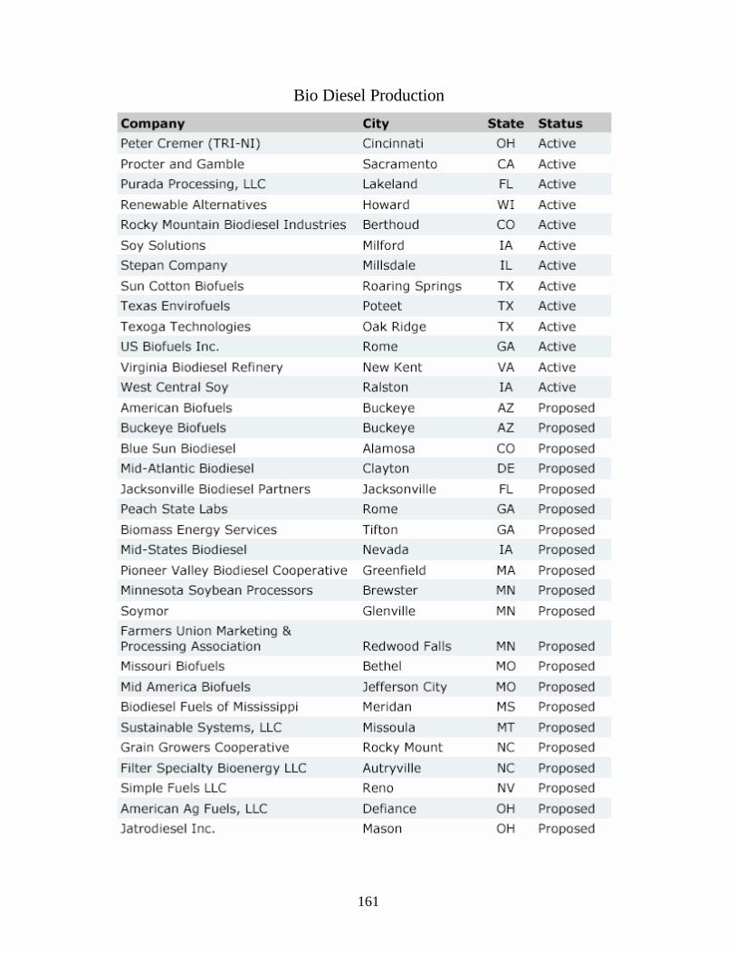
Bio Diesel Production
161

IV-3-7-2. NBB-Member Fuel Producers/Marketers
Ag Environmental Products, Omaha, NE Peter Cremer N.A.; Cincinnati, OH Phone: (800) 599-9209 -- (402) 492-3316 Phone: (513) 471-7200 Contact: Steve Nogel Contact: Mack Findley
e-mail: [email protected] e-mail: [email protected] http://www.soygold.com http://www.cremer-gruppe.com
American Biofuels, North Hills, CA The Procter & Gamble Co.; Cincinnati, OH
Phone: (818) 893-1550 Phone: (513) 626-5351 Contact: William L. "Stretch" Fowler Contact: Scott Kadish mailto:[email protected] email: [email protected]
http://www.pg.com
Baker Commodities; Los Angeles, CA Stepan Company; Northfield, IL PH: (323) 268-2801 Phone: (847) 446-7500
FAX: (323) 264-9862 Contact: Jeff Nelson Contact: Fred Wellons e-mail: [email protected] [email protected] http://www.stepan.com
www.bakercommodities.com
Biodiesel Industries; Santa Barbara, CA West Central Soy; Ralston, IA Phone: 805-683-8103 Phone: (712) 667-3200
Contact: Russ Teall Contact: Don Irmen e-mail: [email protected] e-mail: [email protected] http://www.pipeline.to/biodiesel/ http://www.soypower.net
Corsicana Technologies, Inc., Corsicana, West Central; Ralston, IA TX Phone: (913) 884-8521 Phone: (903) 874-9565 Contact: Gary Haer
Contact: Tom Kowalski mailto:[email protected] e-mail: [email protected] http://www.soypower.net http://www.corsicanatech.com
Filter Specialty Bioenergy, LLC.; World Energy Alternatives; Chelsea, MA Fayetteville, NC Phone: 617.889.7300 Phone: (910) 567-5474 Order Line: (888) 785-8373
Contact: Charles Jackson Contact: Gene Gebolys e-mail: [email protected] e-mail: [email protected]
http://www.worldenergy.net
162

Griffin Industries; Cold Spring, KY Phone: (800) 743-7413
Contact: Hart Moore [email protected] http://www.griffinind.com
Biotane Fuels Imperial Western Products; Coachella, CA Contact: Tom Prokop
Bob Clark [email protected] http://www.biotanefuels.com
Soy Solutions, Ruthven, IA Phone: (712) 338-2223 Contact: Lon Peterson
[email protected] http://www.farmerscoopelev.com
Renewable Alternatives; Green Bay, WI Phone: (920) 217-3548 Contact: Kelly Maloney
Virginia Biodiesel Refinery; Kilmarnock,
VA Phone: (804) 435-1126 Contact: Doug Faulkner
Biodiesel of Las Vegas, Inc., Las Vegas, NV
Phone: (805) 542-0836 Contact: Ben Kulick [email protected]
http://www.3cbiodiesel.com
Environmental Alternatives; Brooklyn, NY
Phone: (718) 972-2156 Contact: Bob Lindenbaum [email protected]
World Energy Alternatives; Nevada City, CA
Phone: (530) 478-9196 Contact: Graham Noyes http://www.worldenergy.net
Archer Daniels Midland; Decatur, IL Phone: (217) 451-6348 Contact: Peter Reimers
http://www.admworld.com e-mail: [email protected]
Gulf Hydrocarbon; Houston, Texas Phone: (800) 834-0202 or (713) 523-7755 Fax: (713) 523.7758
Contact: Jess Hewitt [email protected] http://www.gulfhydrocarbon.com
Grain Growers Cooperative; Rocky Mount, NC Phone: (252) 446-7100
Contact: Sam Lee Jr. [email protected]
US Biofuels Inc; Rome, GA
Phone: (706) 291-4829 Contact: Greg Hopkins [email protected]
Bio-energy Systems; Vallejo, CA Phone: (707) 649-9100
Contact: Jacques Sinoncelli [email protected]
Missouri Better Bean; Bunceton, MO Phone: (660) 427-5444
Contact: Steve Nappier [email protected]
\
163

IV-3-7-3. Biodiesel Distributors in Oregon, Washington, Nevada California and Idaho
Biodiesel distributors in Oregon
Business Name/Location Contact Phone Blend
Albina Fuel Steve Corah 800-888-5048 B20 & 3246 NE Broadway B1 Portland, OR 97232
Hays Oil Co. Steve Hays 541-772-2321 ALL 1890 S. Pacific Hwy Medford, OR 97501
SeQuential Biofuels Ian Hill 541-485-7994 1355 West 1st Ave. Eugene, OR 97402
SeQuential Biofuels Tomas 503-978-3210 All 11330 NW St. Helens Rd Endicott Portland, OR 97231
StarOilco Mark Fitz 503-283-1256 All 232 NE Middlefield Road Portland, OR 97211
Bio-Diesel distributors in Washington
Business Name/Location Contact Phone Blend
Albina Fuel Steve Corah 360-693- B20 & B1 1112 West 7th 4731 Vancouver, WA 98666
Associated Petroleum Frank Pupo, Jr. 253-627- All Products 6179 2320 Milwaukee Way Tacoma, WA 98421
Fuelwerks.com Dan Freeman 206-783- B100 912 NW 50th Street 5728 Seattle, WA 98199
Future Fuels, Inc Peter Diaz 360 480-6452 All 5347 75th Ct SW Olympia, WA 98512
Imagine Energy, Inc Morgan Roose & Nick 206-963- B100 220 Olympic Drive SE Rohrbach 3835 Bainbridge Island, WA 98110
IPS Charlie Meyer 360 378-4430 B100
164

315 Carter Ave. Friday Harbor, WA 98250
Mead Biofuel Marty Mead 360-376- All 4855
Eastsound, WA 98245
Pacific Fluids LLC Mark Tegen 253-284-2244 Port of Tacoma Road 4302 Tacoma, WA 98421
Petro Card Jim Pederson 800-950- All 730 Central Ave. S. 3835 Kent, WA 98032
Pettit Oil Company Sheryl Wiley 253-627- All 1701 Commerce St. 6430 Tacoma, WA 98402
PNEC Mitch Johnson 253-475- All 3037 Center Street 7600 Tacoma, WA 98409
Rainier Petroleum Brad Roberson 206-613- All Corporation 1449 1711 - 13th Avenue SW Seattle, WA 98134
Seaport Petroleum Randall Thomas 206-971- B2, B5, 7800 Detriot Ave SW 7999 B20,B100 Seattle, WA 98106
SeaPort Petroleum Nina Jahne 206-971- All 7800 Detroit Ave SW 7999 Seattle, WA 98106
Shilshole Bay Fuel Dock 206-783- B100 7029 Seaview Ave. NW 7555 Seattle, WA 98117
SoundBiodiesel.com Sam Bryant 360-675- B100 2255 Cove Drive 8252 Oak Harbor, WA 98277
Young Electric Tom Young 509-946- B100 1838 McPherson Avenue 6728 Richland, WA 99352
Bio-Diesel Distributors in CA
Business Name/Location Contact Phone Blend
ApolloPower Dave Lommen 831-421-0234 B100 Santa Cruz, CA 95063
Bay Area Diablo Petroleum Gail Paquette 925-228-2223 B100
165

3575 Pacheco Blvd Martinez, CA 94553
Bio-Friendly Fuel Partners Eric Johnson 925 964-0080 B20, B100
Danville, CA 94526
Cool Fuel, Inc. Christina Hicks 562-259-0100 B20 & up 7201 Rosecrans Avenue Paramount, CA 90723
Cross Petroleum Jimm Cross 530-221-2588 B-100 6920 Lockheed Dr. Redding, CA 96049
CytoCulture Internationa, Inc. Jill Heshmati 510-233-6660 B100 249 Tewksbury Avenue Pt. Richmond, CA 94801
General Petroleum George Hopwood 310-356-2626 B20, B100 19501 South Santa Fe Avenue Rancho Dominguez, CA 90221
General Petroleum Hope Bowles 805-229-1219 B20, B100 3815 Vineyard Avenue Oxnard, CA 93030
Golden Gate Biodiesel Pat O'Keefe 800-244-4516 B2 and up 501 Shell Avenue Martinez, CA 94553
Golden Gate Biodiesel Pat O'Keefe 800-244-4516 B2 & up 820 26th Street Paso Robles, CA 93446
Golden Gate Biodiesel Pat O'Keefe 800-244-4516 B2 & up 8285 Brentwood Boulevard Brentwood, CA 94513
Golden Gate Biodiesel Pat O'Keefe 800-244-4516 B2 & up 1300 Canal Boulevard Richmond, CA 94806
Golden Gate Biodiesel Pat O'Keefe 800-244-4516 B2 & up 1020 Terven Avenue Salinas, CA 93905
Golden Gate Biodiesel Pat O'Keefe 800-244-4516 B2 & up 950 Stockton Avenue San Jose, CA 95110
Ifuel-ITL Incorporated Mary Rohrer 909-277-3160 All 8330 South Atlantic Avenue Cudahy, CA 90201
ii Fuels LLC Ericaka Zenz 714-960-2978 All 7621 Park Forest Drive Huntington Beach, CA 92648
Lee Escher Oil Co., Inc. Jim Combs 760-398-2051 B2 & up 85-119 Avenue 50 Coachella, CA 92236
166

Napa Valley Petroleum, Inc Dave Massey 707-252-6888 All 257 South Kelly Rd American Canyon, CA 94503
Pacific Biofuel Ray Newkirk 831-459-6774 B100 1601 Jarvis Rd Santa Cruz, CA 95065
Party Central Phil Chapman 925-689-9595 B100 1785 Montrose Drive Concord, CA 94519
Pinnacle Petroleum, Inc. Janice Kaufman 949-551-3835 B20, B100 1500 East Pacific Coast Hwy, Ste. F Seal Beach, CA 90740
Plavan Petroleum Inc. Tony Campbell 858-348-2581 All 10635 Scripps Ranch Blvd., Ste. F San Diego, CA 92132
San Francisco Petroleum Rod Martin 707-586-2765 All 4290 Santa Rosa Avenue Santa Rosa, CA 95407
San Francisco Petroleum Rod Martin 707-586-2765 Any 4290 Santa Rosa Avenue Santa Rosa, CA 95407
San Francisco Petroleum, Co. Doug Seames or Barry Viles 415-621-5226 B2 & up 2121 Third Street San Francisco, CA 94107
Supreme Oil Co. Kym Clift 619-542-5020 Any blend 7525 Metropolitan Drive, Ste 304 San Diego, CA 92108
T.W. Brown Oil C., Inc Ted Brown 805-339-2355 B20 B100 1457 Fleet Ave. Ventura, CA 93003
The Soco Group Angus McDonald 800-458-2711 B20 , B100 4915 Mercury Street San Diego, CA 92111
Yokayo Biofuels Kumar Plocher 877-806-0900 B100 150 Perry Street Ukiah, CA 95482
Bio-Diesel Distributors in ID
None
167

Bio-Diesel Distributors in NV
Business Name/Location Contact Phone Blend
Haycock Petroleum Gary Weinberg 702-382-1620 B20, B100 Las Vegas, NV 89015
Total Energy Products Ed Anderson 928-445-0510 B20, B100 Las Vegas, NV 89015
Western Energetix Norma McCusker 775-689-1234 B20, B100 655 West Stanford Way Sparks, NV 89431
168

169