Response History Made…International Participants Join … · submersible centrifugal offloading...
23
Response History Made…International Participants Join in United Effort to Improve Heavy Viscous Oil Marine Response Technology Commander Michael Drieu Lieutenant Commander Peter C. Nourse, PE Chief of Response Special Projects Officer U.S. Coast Guard District Eight (mor) Response Systems Team 500 Poydras St.. Ocean Engineering Division G-SEC-2C New Orleans, LA 70130 U.S. Coast Guard Headquarters 2100 Second St. S.W. Ron MacKay Washington, DC 20593 Senior Response Officer, Charlottetown Rescue, Safety and Environmental Resp. David Cooper, P. Eng. 1 Queen St., P.O. Box 1236 Science Applications International Corp. Charlottetown, PE, C1A 7M8 Canada 335 River Road South Ottawa, ON, K1A 0H3 Canada Flemming Hvidbak flemingCo environmental aps Craig O. Moffat Ajstrup Mosevej 8 GPC/PCCI ESSM Base DK-9381 Sulsted Denmark NWS Cheatham Annex Warehouse #12 Williamsburg, Virginia 23185-5830 James Mackey Hyde Marine, Inc. 28045 Ranney Parkway Cleveland, OH 44145-1144 Abstract The Joint Viscous Oil Pumping System (JVOPS) Workshop was conducted in Houma, LA, USA from 01 – 15 December 2003. The Workshop was planned and executed by the JVOPS Workgroup, a multi-national group of engineers, scientists, pollution response equipment manufacturers and first responders dedicated to improving heavy viscous oil response worldwide. The purpose of the Workshop was to improve the first-response systems of the U.S. and Canadian Coast Guards, the U.S. Navy Supervisor of Salvage, and the international response industry through the evaluation of such systems in a simulated response scenario of extreme viscosity and pumping distance conditions. Marine environmental disasters such as M/V KUROSHIMA (Alaska, 1997), T/B MORRIS J. BERMAN (Puerto Rico, 1994), M/V NEW CARISSA (Oregon, 1999), T/V ERIKA (France, 2001), T/V BALTIC CARRIER (Denmark, 2002), USS JACOB LUCKENBACK (California, 2002), and T/V PRESTIGE (Spain, France, 2002) have demonstrated the limitations of traditional lightering methods, and that innovative techniques are required to offload extremely viscous product. Water lubrication technologies applied to traditional positive-displacement pumps have shown great promise. However, U.S. and Canadian Coast Guard testing of these technologies previous to the JVOPS Workshop had never before combined the simultaneous pumping challenges of both extreme viscosity and long distance. The Workshop targeted testing in the critical 200,000-500,000+ cSt range and pumping distances up to 450 meters. In addition to testing U.S. (DESMI DOP-250) and Canadian Coast Guard (GT-185) pump systems; Framo (Norway) and Lamor (Finland) also had tests conducted on their systems. Technical reports will be public documents.
Transcript of Response History Made…International Participants Join … · submersible centrifugal offloading...

Response History Made…International Participants Join in United Effort to Improve Heavy Viscous Oil Marine Response Technology
Commander Michael Drieu Lieutenant Commander Peter C. Nourse, PE Chief of Response Special Projects Officer U.S. Coast Guard District Eight (mor) Response Systems Team 500 Poydras St.. Ocean Engineering Division G-SEC-2C New Orleans, LA 70130 U.S. Coast Guard Headquarters 2100 Second St. S.W. Ron MacKay Washington, DC 20593 Senior Response Officer, Charlottetown Rescue, Safety and Environmental Resp. David Cooper, P. Eng. 1 Queen St., P.O. Box 1236 Science Applications International Corp. Charlottetown, PE, C1A 7M8 Canada 335 River Road South Ottawa, ON, K1A 0H3 Canada Flemming Hvidbak flemingCo environmental aps Craig O. Moffat Ajstrup Mosevej 8 GPC/PCCI ESSM Base DK-9381 Sulsted Denmark NWS Cheatham Annex Warehouse #12 Williamsburg, Virginia 23185-5830 James Mackey Hyde Marine, Inc. 28045 Ranney Parkway Cleveland, OH 44145-1144 Abstract The Joint Viscous Oil Pumping System (JVOPS) Workshop was conducted in Houma, LA, USA from 01 – 15 December 2003. The Workshop was planned and executed by the JVOPS Workgroup, a multi-national group of engineers, scientists, pollution response equipment manufacturers and first responders dedicated to improving heavy viscous oil response worldwide. The purpose of the Workshop was to improve the first-response systems of the U.S. and Canadian Coast Guards, the U.S. Navy Supervisor of Salvage, and the international response industry through the evaluation of such systems in a simulated response scenario of extreme viscosity and pumping distance conditions. Marine environmental disasters such as M/V KUROSHIMA (Alaska, 1997), T/B MORRIS J. BERMAN (Puerto Rico, 1994), M/V NEW CARISSA (Oregon, 1999), T/V ERIKA (France, 2001), T/V BALTIC CARRIER (Denmark, 2002), USS JACOB LUCKENBACK (California, 2002), and T/V PRESTIGE (Spain, France, 2002) have demonstrated the limitations of traditional lightering methods, and that innovative techniques are required to offload extremely viscous product. Water lubrication technologies applied to traditional positive-displacement pumps have shown great promise. However, U.S. and Canadian Coast Guard testing of these technologies previous to the JVOPS Workshop had never before combined the simultaneous pumping challenges of both extreme viscosity and long distance. The Workshop targeted testing in the critical 200,000-500,000+ cSt range and pumping distances up to 450 meters. In addition to testing U.S. (DESMI DOP-250) and Canadian Coast Guard (GT-185) pump systems; Framo (Norway) and Lamor (Finland) also had tests conducted on their systems. Technical reports will be public documents.

Findings will be used to implement improvements to the systems tested, and to response systems worldwide. JVOPS Workshop Background The Joint Viscous Oil Pumping System (JVOPS) Workshop was conducted at the Cenac Towing Inc. facility in Houma, LA from 01 – 15 December 2003. The Workshop was the culmination of over three years of planning by The JVOPS Workgroup – a volunteer group headed by representatives of the Canadian and U.S. Coast Guards and including pollution responders, engineers, scientists and equipment manufacturers. The purpose of the JVOPS Workshop was to improve heavy viscous oil pumping techniques and technology as applied to marine response. The application of special mechanical techniques to improve heavy viscous oil transfer has been chronicled in detail (Hvidbak, 2003). The positive displacement Archimedes’ screw (PDAS) pump design has been the traditional standard for the transfer of heavy oils in the oil spill response industry. The PDAS pumps best handle heavy viscous oils while minimizing the risk of the creation of emulsion when oil and water are pumped together. However, even these pumps are challenged when transferring extremely viscous oils such as bitumen or very cold heavy oils. In 1999, the work of Bitor, the Canadian Coast Guard (CCG) and Environment Canada (EC) demonstrated that floating bitumen at 2 to 3 million centistokes (cSt.) viscosity could be recovered by mechanical feeder skimmers, and that the standard PDAS pumps of the CCG response inventory were unable to transfer such product without a flow enhancing technique (Cooper and Hvidbak, 2000). Flow Enhancing Techniques The four types of flow enhancement techniques are defined by Hvidbak, as:
a. Bulk Heating – heating of the entire volume of oil to decrease its viscosity. This method may not always be an option as is the case for free-floating skimmers or storage tanks without heating facility.
b. Local Bulk Heating – the placement of a special heating coil wrapped
around the transfer pump or placed in front of its intake; steam supplied to the coils reduces the viscosity of the oil adjacent to the pump, permitting enhanced product inflow into the pump.
c. Discharge Side Annulus Ring Water Injection – the placement of a water
injection flange of special design on the discharge side of the pump. The flange geometry allows metered water to enter the discharge side of the pump at such a velocity and orientation that it creates a water sleeve around the heavy viscous oil. The high friction between viscous oil and hose wall is replaced by much lower friction between water and hose wall, which significantly reduces pressure loss in the hose and allows much greater flow rates and longer pumping distance. In effect, once the material is pushed into the hose, it moves through like water.

d. Inlet Side Annulus Ring Steam/Hot Water Injection – the placement of a water injection flange on the inlet side of the pump through which steam or very hot water is injected to heat up the pump intake, pump and product within immediate vicinity. The technique enhances inflow to the pump and provides lubrication and low friction through both pump and discharge hose.
Previous Work in the Area of Flow Enhancements to Heavy Viscous Oil Pumping Technology The use of flow enhancing techniques to facilitate the pumping of heavy viscous oils is not new. Such techniques were first employed in the 1950’s when the heavy oil industry investigated the use of annular water injection to improve the transfer of heavy viscous crude oil through pipelines. The technique was adapted for use on the discharge side of submersible centrifugal offloading pumps by Framo in the 1990s. The U.S. Coast Guard (USCG) and U.S. Navy Supervisor of Salvage started working with annular water lubrication on the discharge side of a PDAS pumps and organized the first heavy viscous oil Workshop in Seattle, WA, in September 1999. The full-scale testing conclusively showed reductions in system pressures of up to 10-12 times when pumping viscous products. These tests further determined that the water lubrication was effective for hose lengths of at least 450 meters (Moffatt, 1999). This work led to the creation of the USCG Viscous Oil Pumping System (VOPS), a flow enhancement to the USCG’s standard PDAS pump, the DESMI DOP-250, which employs annulus ring water injection to the discharge side of the pump. Shortly thereafter in 2001 in Denmark, Bitor and Ro-Clean DESMI performed breakthrough testing in extreme viscosity pumping by transferring cold bitumen at 3 million cSt 20 meters at 45 m3/h using a DESMI DOP-250 pump with a flemingCo inlet side steam/hot water injection ring (Hvidbak 2001). In 2002, the Canadian Coast Guard (CCG) and Environment Canada (EC) in conjunction with flemingCo environmental took the USCG work a step further and through testing determined that the combination of inlet and outlet side steam/hot water injection could increase the performance of the GT-185 PDAS pump system 40 times when pumping bitumen of 2 million cSt. (Cooper et. al., 2002). Increased Environmental Threat In 2000, the U.S. Coast Guard released a report stating that by 2020, the number of freight vessels carrying crude oil will double in size and number. Cruise ships carry as much as 5,000,000 gallons of heavy fuel oil. Although consumption and thus transportation of such products are on the rise, there are other emerging threats to the environment regarding heavy viscous oils. The Institute for the Analysis of Global Security indicates that future terrorist activities will likely target symbols of economic dominance such as refineries, pipelines and gas facilities. Additionally, it cites that there are increasing signs of collusion between terror and maritime piracy. New International maritime standards for port security in response to potential maritime threats combined with increased maritime use of heavy oils drives the requirement to advance heavy oil recovery technology.

The JVOPS Workgroup: United Efforts in Heavy Viscous Oil Pumping Initiatives Work on the improvement of heavy viscous oil recovery technology in the USCG and CCG had proceeded on parallel courses during this time with no technological cross-connect. While the USCG tests pumped product through hoses up to 450 meters long, the oil used had only a viscosity of up to 27,000 cSt. The CCG had pumped bitumen with viscosity of more than 2,000,000 cSt., but had not attempted to transfer it further than 11 meters. In early 2002, Canadian and U.S. Coast Guard engineers formed the Joint Viscous Oil Pumping System (JVOPS) Workgroup. The chief goal of the Workshop would be to determine the operational envelopes of the response lightering systems of international inventories when subjected to extreme viscosities and pumping distances, and in so doing, determine how to improve them. Flemming Hvidbak of flemingCo environmental (Sulsted, DK) was selected as the project Lead Engineer due to his recent heavy viscous oil pumping work with the U.S and Canadian Coast Guards. The event was advertised internationally. Any and all response agencies or companies were free to participate. Project funding was ensured by establishing a voluntary matrix of project component sponsorship costs to be allocated amongst the participants. The JVOPS Workshop JVOPS Workshop Goals The methods and techniques to achieve the goals were documented in the Technical Approach Strategy (TAS) and later the project Test Plan. In brief, the primary goals were:
a. Determine the maximum operational pumping distance for U.S. Coast Guard pump systems when pumping product of at least 200,000 cSt. viscosity oil using up to 450 meters of 150 mm (6”) hose.
b. Determine the maximum operational pumping distance for Canadian Coast Guard pump systems when pumping product of at least 500,000 cSt. viscosity oil using up to150 meters of 150 mm (6”) hose.
c. Determine the optimal water lubrication combinations and percentages for subject pump systems.
d. Determine the operational capabilities of participating manufacturers’ pump systems and flow enhancing equipment.
e. Investigate local bulk steam heating at the inlet of subject pumps. f. Test a revised-design Annular Water Injection Flange (AWIF); (Discharge
Side Annulus Ring Water Injection) g. Investigate the reestablishment of water lubrication following pump system
shutdown. h. Verify hydraulic pressures and flows vs. pump capacities to determine
pump horsepower efficiency envelopes for pump systems. The viscosity of goal “a.” was to simulate a heavy bunker or No. 6 fuel oil when subjected to cold ambient temperatures of seawater during maritime disaster. The viscosity of goal “b.” was to simulate the extreme viscosity of bitumen.

The concept of Workshop testing and test support activities were well thought out in advance and documented in the Test Plan. Figs. 2 and 3 show the sequence of major events during testing. Although the main theme of the Workshop was data acquisition, there was additional value to the Workshop. Participants learned about and gained more experience with their pump systems. The combinations of extreme viscosity and pumping distance, coupled with the infrastructure required to support such a test inherently resembled an actual marine heavy viscous oil recovery response. Additionally, Canadian and U.S. Coast Guard personnel labored to set up and maintain operation of their pump systems under challenging conditions similar to those encountered in a real-world maritime response. Pump Systems Tested Two pump systems from the U.S. and Canadian Coast Guard’s response inventory, and pumps from Lamor, (Finland) and Framo (Norway) were tested. The models and salient characteristics of the various tested pumps are displayed in Table 1. Table 1 Test Pumps and their Characteristics
Pump Manufacturer Type Capacity
(m3/hr)
Weight (kg)
Max. Standard Discharge Press 2
(bar) DOP-250 Desmi
(Denmark) PDAS 62.5 (100)1 75 10
GT-A 50 Lamor (Finland)
PDAS 50 (62.5) 47 12
TK-125 Framo (Norway)
Double-Screw
52 86 25
GT-185 (with prototype heavy duty plate wheel)
G. Terling AB (Sweden). Brand owned by Lamor
PDAS 27 (45)1 81 7
1 Capacity with high-torque version of hydraulic motor used in JVOPS Workshop testing. Parenthesis value is capacity with standard hydraulic motor. 2 All pumps were in the JVOPS Workshop tested up to 12 bar. The Desmi DOP-250 pump is the standard lightering pump of the U.S. Coast Guard. The GT-185 pump is the standard lightering pump of the Canadian Coast Guard. See Fig. 1 for photos of tested pumps. Due to the high viscosity of the test product, the Desmi DOP-250, the GT-185, and the Lamor GT-A 50 pumps were fitted with higher torque hydraulic motors and all four pumps were fitted with flow enhancement devices. The DOP-250 was fitted with a Danfoss OMTS 315 motor, a U.S. Coast Guard VOPS discharge side Annular Water Injection Flange (AWIF), and a flemingCo type inlet side AWIF. The GT-185 was fitted with Ross ME 15 hydraulic motor, a high pressure/high temperature plate wheel, and flemingCo type inlet and outlet AWIFs. The Lamor GT-A 50 was fitted with a Danfoss OMTS 200 hydraulic motor. The GT-A 50 pump has a flemingCo inlet-side AWIF, which is built into the casing of the pump, and was also fitted with a flemingCo discharge side AWIF. The

Framo TK-125 pump was equipped with a Framo discharge side AWIF and a 10 mm water injection tube on the inlet. See Fig. 1. JVOPS Workshop Chief Challenges - Test Facility, Test Product, and Viscosity Control The JVOPS Workshop was conducted at the Cenac Towing, Inc. facility in Houma, Louisiana, USA. Cenac Towing is the fifth largest towing company in the U.S. and had offered the use of their facility at no cost to the JVOPS project. The company maintains a genuine, active interest in promoting heavy viscous oil pumping technology. However, perhaps the greatest challenge of this project was obtaining a test product, which would be suitable to achieve Workshop goals. The product would have to meet both the target viscosity of the U.S. Coast Guard portion of tests (200,000 cSt.) and the target viscosity of the Canadian Coast Guard portion of tests (500,000 cSt.). In Spring 2003, the Workgroup located a heavy crude bitumen from the Japan Canada Oil Sands Project near Fort McMurray, Alberta. Workgroup viscosity testing showed that the product should achieve close to target viscosities during Houma’s Winter months. 500 barrels of the product were secured and shipped via railroad to Louisiana and three heated oil tank trucks handled local transportation to the test facility. The product’s viscosity curve is shown in Fig. 2. Figure 1. The Pumps Tested at the JVOPS Workshop. Clockwise from left-top: Canadian
Coast Guard GT185, Lamor GT-A 50, U.S. Coast Guard Desmi DOP-250, and Framo TK-125. The arrows denote the inlet and outlet water lubrication devices within or attached to each pump.
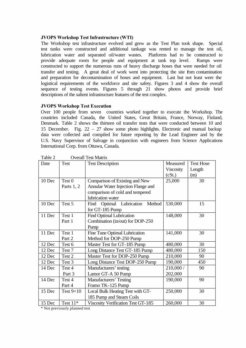
JVOPS Workshop Test Infrastructure (WTI) The Workshop test infrastructure evolved and grew as the Test Plan took shape. Special test tanks were constructed and additional tankage was rented to manage the test oil, lubrication water and separated oil/water wastes. Platforms had to be constructed to provide adequate room for people and equipment at tank top level. Ramps were constructed to support the numerous runs of heavy discharge hoses that were needed for oil transfer and testing. A great deal of work went into protecting the site from contamination and preparation for decontamination of hoses and equipment. Last but not least were the logistical requirements of the workforce and site safety. Figures 3 and 4 show the overall sequence of testing events. Figures 5 through 21 show photos and provide brief descriptions of the salient infrastructure features of the test complex. JVOPS Workshop Test Execution Over 100 people from seven countries worked together to execute the Workshop. The countries included Canada, the United States, Great Britain, France, Norway, Finland, Denmark. Table 2 shows the thirteen oil transfer tests that were conducted between 10 and 15 December. Fig. 22 – 27 show some photo highlights. Electronic and manual backup data were collected and compiled for future reporting by the Lead Engineer and by the U.S. Navy Supervisor of Salvage in conjunction with engineers from Science Applications International Corp. from Ottawa, Canada. Table 2 Overall Test Matrix Date Test
Test Description Measured
Viscosity (cSt.)
Test Hose Length (m)
10 Dec Test 0 Parts 1, 2
Comparison of Existing and New Annular Water Injection Flange and comparison of cold and tempered lubrication water
25,000 30
10 Dec Test 5 Find Optimal Lubrication Method for GT-185 Pump
530,000 15
11 Dec Test 1 Part 1
Find Optimal Lubrication Combination (in/out) for DOP-250 Pump
148,000 30
11 Dec Test 1 Part 2
Fine Tune Optimal Lubrication Method for DOP-250 Pump
141,000 30
12 Dec Test 6 Master Test for GT-185 Pump 480,000 30 12 Dec Test 7 Long Distance Test GT-185 Pump 480,000 150 12 Dec Test 2 Master Test for DOP-250 Pump 210,000 90 12 Dec Test 3 Long Distance Test DOP-250 Pump 190,000 450 14 Dec Test 4
Part 3 Manufacturers’ testing Lamor GT-A 50 Pump
210,000 / 202,000
90
14 Dec Test 4 Part 4
Manufacturers’ Testing Framo TK-125 Pump
190,000 90
15 Dec Test 9+10 Local Bulk Heating Test with GT-185 Pump and Steam Coils
250,000 30
15 Dec Test 11* Viscosity Verification Test GT-185 260,000 30 * Not previously planned test

Bitumen Viscosity vs. Temperature Dec 03Analysis performed on Brookfield DVII+ Rotary Viscometer
w/Small Sample Adaptor spindle #27 @ Shear Rate of .07 sec^(-1)
20000400006000080000
100000120000140000160000180000200000220000240000260000280000300000320000340000360000380000400000420000440000460000480000500000520000540000560000580000600000
15 16 17 18 19 20 21 22 23 24 25 26 27 28 29 30 31 32 33 34 35
Temperature Degree C
Ce
nti
sto
ke
s
Figure 2. Viscosity Curve For the JVOPS Test Produc

Figure 3. General Test Layout for USCG Tests and Sequence of Events: Water Lubrication Control Stand (WLCS) and Water Lubrication Injection Tanks (1) provide water at various temperatures and flow percentages to the Test Pump in the USCG Test Tank (2). The Test Pump (2) pumps product through the instrumented test hose circuit (3). The test hose circuit length can be varied seamlessly during pumping by engaging the Swift Hose Add-on System (SHAS) manifold (4). This adds sequential lengths of test hose upwards to 1500’. Drum Filling (6) weighs the product flow to determine actual product flow rate. Product is pumped out of the 200 Barrel Collection Tank (5) by the pump (7) onto the Brush Skimmer (8) and into the Baker Tank (9), which is the source of 200,000 centistoke test product. The Brush Skimmer delivers pure test product back to the Baker Tank (9) by allowing the injected water to gravity flow through it and into the Oily Water Collection Tank (10). The USCG Test Tank (2) is fed more test product from (as needed) from the Baker Tank (9) by the pump (12). Temperature and resulting viscosity is maintained within Baker Tank (9) by the Chiller System (11) which feeds cold water to the nozzles on the Baker Tank.
1
2
3
4
5
6
7
9
11
12 10

Figure 4. General Test Layout for Canadian Coast Guard Tests and Sequence of Events: Layout and sequence similar to USCG Testing. Major differences are that smaller 70 Barrel Canadian Coast Guard Test Tank (1) contains 500,000 centistoke test product (vs. 200,000 centistoke test product) and is not fed product by the Baker Tank. Also, (2) a Belt Skimmer (vs. Brush Skimmer) is used to gravity separate injected water from test product.
1
2

Figure 5. The Baker (Backup) Tank. It was shaded prior to testing, then insulated just prior to and during testing. Test Product was re-circulated within for 2 months prior to actual testing. A water sprinkler system was installed (under insulation) to enhance evaporative cooling. Nine temperature probes within were monitored on a daily basis before and during testing. .
Figure 6. Shading and Water Cooling of the Canadian Coast Guard Test Tank. A sprinkler system enhanced evaporative cooling. Two temperature probes were monitored daily. Tank was insulated just before testing.
Figure 7. The USCG Test Tank (foreground) and Canadian CG Test Tank (background) From Atop the Baker Tank. Once the Test Product assimilated to the average ambient temperatures and resulting target viscosities were achieved, insulation was added to the tanks in November to maintain viscosities.

Figure 8. The U.S. Navy Steam Generator. This provided steam supply for water lubrication and steam coil devices.
Figure 9. Water Lubrication Injection Tanks. Shown (background) is tank with boiling water supply for Water Lubrication Control Stand (WLCS).
Figure 10. The Chiller System. This was essential to maintain target viscosities for both USCG and CCG Test Products. The system was closed-loop ensuring no oil contamination of the bayou or ground.
Figures 11 and 12. The Swift Hose Add-on System (SHAS). This device was specially designed for use only on this project. Its purpose was to seemlessly increase the length of discharge test hose by locking in sequential lengths of test hose during testing without disrupting the water lubrication phenomena . Use of this device significanly reduced the amount of test hose required for each test thereby reducing on-site hose decontamination time. Figure 11 shows the SHAS mounted for USCG Testing. Figure 12 shows the SHAS in use.

Figure 13. Water Lubrication Control Stand (WLCS). This device was specially designed for the Workshop. Its purpose was to quickly change lube water temperature, accurately control flow rate, and collect data on flow rate, temperature and pressure of lubrication water during testing. The operator could switch between two inlet lube water sources and two outlet lube water sources and control the flow rate delivered to the water lubrication devices on a test pump. The overall water lubrication system consisted of three insulated and temperature controlled tanks, four continuously operating pumps with pressure relief valves, water delivery hoses and the WLCS. A High Capacity Boiler and Chiller were used to control water temperature.
Figure 14: The Lamor Brush Skimmer. This heavy oil skimmer was provided as in-kind services by the Lamor Corporation of Finland to return test product from the test hose circuits back into the Baker Tank. It essentially separated the water added to the test product during water lubrication from the heavy product so that it could be reused for further testing.
Figure 15: The Data Acquisition Suite. Data Acquisition was provided jointly by the U.S. Navy Supervisor of Salvage and Scientific Applications International Corporation of Ottawa, Canada.

Figures 16 and 17. U.S. Navy Pig Launcher (left) and Catcher (right). The Pig Laucher is a simple device consisting of a “Y” pipe into which is fed compressed air to push the pig. Pigging was successfully executed to clean test hose circuits following all tests at 120 psi. The Pig Catcher is a simple aluminum box which catches the pig on the far end of the test hose. The one shown here was modified to drain the pushed product into the 200 BBL tank below.
Figures 20 and 21. Canadian and U.S. Coast Guardsmen Work Together to Prepare Pumps for Testing.
Figure 18. Loading the Scraper Pig Figure 19. Pre-Testing Training. Significant amounts of training were conducted prior to actual testing.

Figures 22 and 23. Lubricated Flow. Shown is the The Water Lubrication “Ring” Surrounding the Heavy Viscous Product During USCG Testing
Figure 25. The SHAS and ERE Belt Skimmer. The Environmental Recovery Equipment (ERE) Skimmer sat atop the CCG Test Tank and separated lubrication water from the returning Test Product for follow on tests.
Figure 26 (left). U.S. Navy Steam Coil Around GT-185 Pump.
Figure 24. Pure product flow without water lubrication. The effects of water lubrication cannot be overstated.

JVOPS Test Results The magnitude of data retrieved during the many tests will together with a comprehensive analysis be disclosed in the Final Report. This will be available as a public document in summer 2004. However, for the purpose of this presentation, several of the most remarkable results have been extracted and are presented. Reference is made to the test identification numbers. in Table 2. Pre-Testing Some pre-tests (Tests 0, 1, and 5) were executed at both test lines, primarily to evaluate which lubrication water percentages and temperatures to use. The pumping distances were 20.6 m (CCG) and 32.3 m (USCG). It appeared, however, that the water lubrication worked so well that differences in performance between different temperatures and water injection rates were marginal over these short pumping distances. Nevertheless the decision was made to use 4% in and 4% out combinations as the “best”, even though testing had revealed that as low as 2% in and out might be as efficient, at least once the fully lubricated flow had been established After two USCG pre-tests on 25,000 cSt oil at 41 ºC water (Test 0) where only outlet lubrication was applied, it was determined that a re-designed outlet lubrication flange for the USCG VOPS DOP-250 pumps, with a claimed more uniform distribution of the lube water around the oil core, did not perform better than the original VOPS flange. In the same test 18 ºC water seemed to lubricate slightly better than 33.5 ºC water (closer to that of the oil), but to avoid complicated chilling and control of the cold lube water, the decision was made to use ambient temperature water (about 16 ºC) as “cold” water for the main tests. Hot lube water would be in the 85 to 99 ºC range. The main tests involved oil at about 21 ºC (USCG test line, 200,000 cSt) and 16 ºC (CCG test line, 500,000 cSt). The viscosity vs. temperature curve can be seen in Fig.2. Test Procedures Each test involved several different combinations of water injection % and cold vs. hot water, which was controlled by the specially developed Water Lubrication Control Stand (WLCS). Switching from one mode to the other could be done without interrupting the pumping process. It should be noted that the test procedure as per the Test Plan required that the expectedly best lube method always be initiated first, followed by the next best etc., and with baseline run (no lubrication) last. The ranking was based on findings in the previous extreme viscosity pump tests in Denmark and Canada. The purpose of this procedure was to avoid unnecessary contamination of the inner hose wall prior to the next run. The alternative would have been to use new clean hoses for each run, but this was not an option due to time constraints and because hose cleaning costs would be exceedingly expensive. Likewise to save time and hose cleaning, the switch from the Master Tests to long distance testing was carried out using the Swift Hose Add-on System (SHAS), which made it possible to add on new hose sections without interrupting the pumping and water lubrication processes. See Figs. 11 and 12.

To facilitate establishing and maintaining the annulus water lubrication ring all test hoses were primed with about 100 liters of water prior to any oil transfer. The water would be pushed in front of the oil through the hose to ensure wetting of the inner hose wall. This procedure is important for responders to observe. Selected Test Results Data analysis has not been 100% completed at the time of writing this paper but some key preliminary results are presented in Tables 3 to 6. Key data like hose length, viscosity, lube water %, lube water temperature, pump capacity, and pump pressure should provide a clear understanding of how successfully the pumping of oil at these high viscosities was carried out. A tool to be used in the evaluation of the tested pump systems is the Performance Improvement Factor (PIF), which was defined by the project Lead Engineer. PIF = Pressure drop(no lube) / Pressure drop(with lube) x Capacity(with lube) / Capacity(no lube) As special variant of the PIF is used where in-flow to the pump and not pressure is the limiting factor in baseline testing without water lubrication (See Table 3). Table 3 displays some of the test runs with the CCG GT-185 pump, which had been equipped with a re-designed high pressure/high temperature plate wheel, in addition to the water injection devices and high torque motor. The first two runs from Test 5 show hot water in and out percentages as low as 1.7 % and 1.7 % without influencing the already very low pressure drop. The runs of Tests 6 and 7, Master Test and long distance testing, show proportionality in pump pressure going from 20.6 m (Test 5) to 32.4 m, but a remarkable lack of proportionality going from 32.4 m. to 152.4 m. The phenomenon is still being reviewed. Our best theory to explain this event is that the annulus water ring stabilizes and gets closer to ideal over time when pumping this very viscous oil. Table 3 Tests with GT-185 w. flemingCo inlet and outlet AWIFs Test/Hose length Test#/(m)
Viscosity cSt
Inlet lube water % / ºC
Outlet lube water % / ºC
Calculated capacity m3/h
Drum-fill capacity m3/h
Pump pressure* bar
PIF value**
5 / 20.6 530,000 4 / 81 4 / 81 26.8 26.1 0.4 >1100 5 / 20.6 530,000 1.7 / 80 1.7 / 80 27.5 23.4 0.4 >1100 6 / 32.4 480,000 4 / 98 4 / 19 26.6 27 0.6 >1700 7 / 152.4 480,000 4 / 98 4 / 19 26.6 25.5 0.9 >8000 7 / 152.4 480,000 4 / 97 none 26.6 26.6 0.8 >8000 11 / 32.4 260,000 4 / 93 4 / 35 24.1 25.7 0.4 n/a * Note that a static lift of 1.5 m or 0.15 bar has not been deducted to show the true pressure drop in the hose and fittings (does not apply to Table 11 test on 260 k cSt oil that was carried out in the USCG test tank). **PIF: A dedicated baseline test was not carried out, but it was recorded that it took 65 minutes to fill a 30 m long 6” hose without any water lube (0.5 m3/h). The pump pressure and power consumption were very low since the sole limiting factor was the pump’s inability to drag in the viscous oil without aid from hot water injection on the inlet side. The capacity would therefore not be expected to increase even if hose length was shortened to 1 meter. PIF values are therefore estimated only and are based on test hose length (baseline set to 1 m) and capacity increase. PIF GT-185 = test hose length / 1m x capacity (w. lube) / capacity (no lube).

The second run of test 7 shows excellent performance when hot water is injected on the inlet side of the pump only. Test 11 was carried out as test 6 but with oil of significantly lower viscosity in search of a relationship between viscosity and pressure drop. As can be seen the pressure drops from 0.6 to 0.4 bar going from 480 k cSt to 260 k cSt. This is a relative reduction of 33 %, but if measured under real world conditions, the difference would not be noticeable. Figure 27 Discharge of 480,000 cSt oil and lube water in 150 m test with GT-185 Table 4 contains selected test runs from testing in the 200 k cSt range with the USCG VOPS DOP-250 pump. Table 4 Tests with DOP-250 w. flemingCo inlet AWIF / USCG/Navy outlet AWIF Test/Hose length Test#/(m)
Viscosity cSt
Inlet lube water % / ºC
Outlet lube water % / ºC
Calculated capacity m3/h
Drum-fill capacity m3/h
Pump pressure bar
PIF value
0 / 32.3 25,000 n/a 3 / 29 79 n/a 0.3 n/a 1 / 32.3 145,000 0 0 19 18 11.9 n/a 1 / 32.3 148,000 4 / 99 4 / 26 60 60 0.4 94 2 / 92.3 210,000 0 0 5.9 n/a 12.5 n/a 2 / 92.3 210,000 4 / 99 4 / 18 58.2 57.3 0.5 246 2 / 92.3 210,000 4 / 99 4 / 18 55 54.1 1.2 97 3 / 452.3 190,000 4 / 97 4 / 19 59 n/a 4.1* 152 * ** 3 / 452.3 190,000 6 / 18 0 60.7 58,4 3.0 214 ** * Electronic data shows that the pressure was still dropping at time of reading ** PIF calculation with factor 5 incorporated for 5 times longer hose length. Not exact because of slightly lower viscosity, but still a good indication The first row is from Test 0 and shows a run on 25,000 cSt oil using the standard USCG outlet AWIF and applying 3% cold-tempered lube water. Second row is the baseline run (no lube) of Test 1, which should be compared with the run in row 3 from the same test

(4% hot water on the inlet and 4% cold water on the outlet). Note the drastic reduction in pump pressure while at the same time increasing the capacity more than 3 times. The performance improvement factor (PIF) between these test runs is 94. The examples from Test 2 (Master Test) in lines 4 and 5 show baseline testing and a run with 4% hot inlet and 4% cold outlet lube water. Note again the dramatic improvement. A factor 25 reduction in pump pressure while simultaneously increasing the capacity almost 10 times give a PIF value of 246! In Test 2 it was further verified that re-establishing the annulus water lubrication ring after the baseline testing (here simulating an unintended pump stop and break down of water ring) was not possible using cold water, but was successfully accomplished using 4% hot inlet and 4% hot outlet water. This is important knowledge for responders. The third run shown from Test 2 is a repetition of the test just above, but this time with the test hose inner walls contaminated with sticky oil after the baseline testing. Note the increased – but still very low pump pressure, as well as the reduced PIF. This was a very important run since it better than the run above reflects real world conditions where clean hoses only can be expected the very first time they are used in a response situation. The last two rows in Table 4 are runs from the long distance testing with 452.3 m hose length. This testing was conducted immediately after completion of Test 2 without stopping, using the SHAS to add on 360 meters of hose. For comparison with the 92.3 m testing, the last listed Test 2 run should be used since this run also was with a contaminated hose. There is an unexpected lack of proportionality between hose length and pump pressure, although not as significant as in the results with the GT-185. Most surprising from an initial evaluation of data is the only 13% power increase going from 92.3 to 452.3 m hose. The small power increase could indicate that a large amount of the consumed power was used to rotate the pump in the viscous oil, i.e. to overcome friction inside the pump. Table 5 shows test results with the Lamor GT-A 50 pump from the Manufacturers’ testing, which used the same setup as USCG Master Test (Test 2). Table 5 Test with Lamor GT-A 50 w. flemingCo inlet and outlet AWIFs Test/Hose length Test#/(m)
Viscosity cSt
Inlet lube water % / ºC
Outlet lube water % / ºC
Calculated capacity m3/h
Drum-fill capacity m3/h
Pump pressure bar
PIF value
4.3 / 92.6 202,000 0 0 4.5 6.1 11.9 n/a 4.3 / 92.6 210,000 4 / 98 4 / 98 46.7 42.7 0.6 * 206 4.3 / 92.6 210,000 4 / 99 4 / 14 45.7 40.5 0.6 ** 201 4.3 / 92.6 210,000 4 / 14 4 / 14 44.8 43.2 2.8 42 * Electronic data shows that the pressure trend was still slightly downwards at time of reading ** Electronic data shows that the pressure trend was still slightly upwards at time of reading The first row shows the baseline test run without lube water. It should be noted that the calculated capacity based on hydraulic flow reading may be too low, based on the drum-fill

data, which is very precise at low pumping rates. Further the drum-fill capacity correlates best with the baseline capacity for the DOP-250 (Table 5). In fact, with the same pump pressure, the baseline capacity must be the same since only the pressure determines how much oil can be pushed through a hose of a given length when the viscosity is about the same. For consistency, PIFs have been calculated using the calculated capacity for all pumps. Rows 2 to 4 represent different combinations of lube water, with hot in/hot out probably being the best combination since the pressure curve was still dropping at time of reading. The cold in / cold out combination performed significantly different from similar tests with the other pumps. The phenomenon is still being studied, but one reason could be that this test used the coldest “cold” lube water of all tests. Another reason could be that the Lamor pump has small dimensions compared to the delivered capacity. The pump is about half the size of a DOP-250, dimension wise and standard capacity wise, but it delivered about 80% of the DOP-250 capacity during this test. Small inner dimensions and thereby smaller cavities and less open structure must be considered to cause more friction and less optimal conditions for establishing close-to-perfect water lubrication. The larger GT-A 115 pump of similar size as the DOP-250 would probably have offered more ideal conditions friction and lubrication wise. Table 6 shows test results with the Framo TK-125 double screw pump from the so called Manufacturers’ testing, which used the same setup as USCG Master Test (Test 2). This was the longest and most time consuming test. The test started with numerous attempts to make the pump drag in the oil and to establish water lubrication. Low rpm as well as high rpm and several water lubrication combinations were tried. It was throughout the test observed that there was visually very little correlation between apparent pumping rate and what came out of the discharge end of the test hose. It was not possible to complete any of the test runs in their entirety, but the registered results have been inserted to provide a picture of the performance. Table 6 Framo TK-125 w. 10 mm inlet injection tube and Framo discharge AWIF Test/Hose length Test#/(m)
Viscosity cSt
Inlet lube water % / ºC
Outlet lube water % / ºC
Calculated capacity m3/h
Drum-fill capacity m3/h
Pump pressure bar
PIF value
4.4 / 92.1 190,000 0 0 5.7* n/a 2.8 n/a 4.4 / 92.1 190,000 7 / 95 7 / 94 51.8 12.3 (24%) 0.4 60 4.4 / 92.1 190,000 7 / 98 7 / 19 51.8 12.3 (24%) 0.7 35 * Calculated capacity does not correlate to other baseline tests. Actual product flow must have been approx. 25% of this value, determined by the pump pressure. Has been used in PIF calculation. Note: No test runs were completed due to time constraints. The results clearly indicate that even though the pump never pumped more than 24% of the apparent capacity based on hydraulic flow, the pressure reduction and capacity increases were achieved when using water injection. However, this performance improvement was only when hot water was applied at the inlet. Attempts were made to lubricate the inlet with cold water, but immediately the pump pressure rose and in effect caused the pressure relief valve on the power pack to activate (about 220 bar). This again turned the hydraulic

flow to the pump almost to 0. There were several signs of a hydraulic motor with too little torque for the task. The inlet opening of the TK-125 seems to be too small for this type of oil. In addition the cavities inside the pump are relatively small, and the screws rotate tight against each other. This develops very high friction with this type of oil, unless the oil is accompanied by hot water. Unfortunately this type of pump is for design reasons not suitable for water pumping and with inlet water injection it cannot be avoided that the pump sometimes must pump pure water. The TK-125 double screw pump with its water injection devices as tested may not be suitable for oil at these high viscosities. One of the last tests that were carried out was Test 10 where local bulk heating coils were used without and in conjunction with water lubrication. The data are still undergoing analysis and are not yet ready for publication. The results will be presented in the final report. JVOPS Workshop Conclusions The JVOPS Workshop was a great success with significant positive results reducing hose pressure and increasing flow rates to a degree that must be considered groundbreaking. Never before had so diverse a group of marine pollution responders worked together to improve heavy viscous oil lightering technology under extreme conditions of viscosity and pumping distance. General Test Observations. The Final Report will present Conclusions based on completed analysis of the test data but the following General Observations can be made: • The tests in the 20, 30, 90, 150, and 450 m hose length ranges indicated no requirement
for additional lube water when increasing the pumping distance. • The three PDAS pumps tested, DOP-250, GT-185 and GT-A 50, with their respective
water injection devices, can be considered most suitable for pumping oil at these high viscosities.
• Based on the obtained results there is reason to expect that other PDAS pump sizes, using the best water lubrication combination, will perform reasonably proportionally.
• There is also reason to expect that larger pumps, with larger internal cavities, should perform relatively better as long as hydraulic motors of sufficiently high torque are installed.
• The recorded pump performance data, initial calculations on increased power consumption for increased hose length, and the maximum allowed power input to the hydraulic motors, indicate that: • The GT-185 should be able to deliver this 500,000 cSt oil at nearly full capacity
through up to 225 m of 150 mm (6”) hose. • The DOP-250 and the GT-A 50 should be able to deliver this 200,000 cSt oil at
nearly full capacity through up to 800 m of 150 mm (6”) hose. • Cross calculations for the GT-185 on 200 k cSt oil and for the DOP-250 and GT-A
50 on 500 k cSt oil have not yet been made but will be part of the final report.

• Although it is not covered in this paper, many very valuable lessons were learned
and new techniques used for cleaning the hundreds of meters of heavily contaminated discharge hose. Developments include a unique diesel flush and pigging technique that could be used in future by responders. More information is available from the JVOPS Workgroup members.
JVOPS Workshop Follow on Work A strategy was developed prior to the Workshop to establish a near-term final goal for the joint work throughout 2004 and beyond with milestones at significant points. Remaining milestones include:
• Issue Final Report (Public Document) (Summer 2004)
• Improvement of Existing U.S. and Canadian Coast Guard Viscous Oil Pumping Systems (VOPS) based upon Final Report recommendations (2005)
• Continued R&D for flow enhancement technology for pumping very viscous oils in
an Arctic Environment
• Continued R&D to explore alternative pumping enhancement methods other than injection lubrication for very viscous oils
The challenge in improving existing VOPS’s will be to implement mechanical improvements while keeping the overall system manageable by the operating personnel. Acknowledgements Special acknowledgements are due to Cenac Towing of Houma, LA. The use of their facility and services in-kind for the Project venue are most heartily appreciated by the JVOPS Workgroup. This project, what will surely be a breakthrough in response technology, would not have happened without their support. Special acknowledgements are also due to the Oil Spill Response Institute (OSRI) of Cordova, AK and Alaska Clean Seas of Prudhoe Bay, AK. The support provided by both organizations was a key in completing the JVOPS Workshop. References Hvidbak, F., flemingCo environmental. (2003). Positive Displacement Archimedes’ Screw Pumps and Flow Enhancing Techniques. Essential Tools in Response to Spills of Heavy Oil and Bitumen. Proceedings of the 26th Artic and Marine Oil spill Program Technical Seminar. Moffatt, C., GPC, U.S. Coast Guard and U.S. Navy, 1999. Testing of the U.S. Coast Guard Viscous Oil Pumping System (VOPS Prototype) at the MMS OHMSETT Test Facility, Earle, NJ, November 1999. USCG/US Navy/GPC Technical Report 19

Suggested Additional Reading Cooper, D. (2001). Heavy Oil / Orimulsion Pumping Annular Ring Evaluation V1.01 – Final Report, Science Applications International Corporation (SAIC Canada) Environmental Technologies Program. SAIC Canada, Tech. Report No. B187-328, B365-000, Pages 1-26. Cooper, D., Hvidbak, F, Mitchell, T, (2002). Pumping Extremely Viscous Oil Using A Modified GT – 185. Emergency Engineering Technologies Office – Environment Canada, Canadian Coast Guard Fisheries and Oceans – Final Report, Science Applications International Corporation (SAIC Canada) Environmental Technologies Program. SAIC, Canada. Tech. Report No. B187-427, B431-000, Pages 1-26. Cooper, D., MacKay, R. (2001). Assisted Pumping of Extremely Viscous Oils. Proceedings of the 24th Artic and Marine Oil spill Program (AMOP) Technical Seminar, Environment Canada, Ottawa, Ontario, Vol. 1, pages 373-386. Cooper, D., SAIC Canada, Hvidbak, F., flemingCo, (2000). Evaluation of Mechanical Recovery Devices for Spills of Orimulsion®. SAIC Canada Technical Report, 2000. Drieu, M., Loesch, R. (2000). Learning from the Tough Ones: U.S. Coast Guard Viscous Oil Pumping Improvements. Proceedings of the 23rd Arctic and Marine Oil spill Program Technical Seminar. Vol. 1. Pages 415-428. Drieu, M., Nourse, P. (2002). The U.S. Coast Guard Viscous Oil Pumping System (VOPS): Through Successful Partnership Amongst the U.S. Coast Guard (USCG), U.S. Navy and Maritime Industry. International Maritime Organization Third Research and Development Forum on High Density Oil Spill Response Proceedings. IMO, London. Pages 445-448. Drieu, M., Nourse, P, MacKay, R, Cooper D, Hvidbak, F. (2002). Latest Update of Tests and Improvements to Coast Guard Viscous Oil Pumping System (VOPS) (2002), International Oil Spill Conference 2003 Proceedings. Hvidbak, F., flemingCo environmental. (2001). The Development and Test of Techniques for Emergency Transfer of Extreme Viscosity Oil. Proceedings of the 24th Artic and Marine Oil spill Program Technical Seminar, Environment Canada, Ottawa, Ontario. Vol. 1, pages 339-356. Hvidbak, F., flemingCo environmental. (2001). Bitumen Pump Transfer Test at DESMI 2001-02-20 to 03-01, Bitor (PDVSA) Technical Report.