
Pompe Framo
175
Framo Mounting Instruction Main contents 1 Introduction 1401-0001-401 2 Location on board 1401-0002-401 3 Equipment handling - Storage at yard 1401-0003-401 4 Installation of submerged cargo pumps 1401-0004-401 5 Installation/Storage of portable equipment 1401-0005-401 6 Installation of submerged ballast pumps 1401-0006-401 8 Installation Installation of Installation of hydraulic Installation of hydraulic power Installation of hydraulic power unit, Installation of hydraulic power unit, closed Installation of hydraulic power unit, closed loop Installation of hydraulic power unit, closed loop system 1401-0034-4 9 Installation of electrical equipment 1401-0009-401 10 Yard equipment 1401-0010-401 12 Install ation of deck mounted car go heat exc hangers 1401-0012- 401 14 Installation of submerged tank cleaning pumps 1401-0026-4 17 Hydraulic piping 1401-0017-401 18 Cargo piping 1401-0018-401 19 Hydraulic oils - Oil filling - Flushing 1401-0019-401 20 Framo commissioning - Testing 1401-0020-401 June 2003
-
Upload
sorescu-radu-vasile -
Category
Documents
-
view
1.345 -
download
124
Transcript of Pompe Framo
7/16/2019 Pompe Framo
http://slidepdf.com/reader/full/pompe-framo 1/175
Framo
Mounting Instruction
Main contents
1 Introduction 1401-0001-401
2 Location on board 1401-0002-401
3 Equipment handling - Storage at yard 1401-0003-401
4 Installation of submerged cargo pumps 1401-0004-401
5 Installation/Storage of portable equipment 1401-0005-401
6 Installation of submerged ballast pumps 1401-0006-401
8InstallationInstallation ofInstallation of hydraulicInstallation of hydraulic powerInstallation of hydraulic power unit,Installation of hydraulic power unit, closedInstallation of hydraulic power unit, closed loopInstallation of hydraulic power unit, closed loopsystem
1401-0034-4
9 Installation of electrical equipment 1401-0009-401
10 Yard equipment 1401-0010-401
12 Installation of deck mounted cargo heat exchangers 1401-0012-40114 Installation of submerged tank cleaning pumps 1401-0026-4
17 Hydraulic piping 1401-0017-401
18 Cargo piping 1401-0018-401
19 Hydraulic oils - Oil filling - Flushing 1401-0019-401
20 Framo commissioning - Testing 1401-0020-401
June 2003
7/16/2019 Pompe Framo
http://slidepdf.com/reader/full/pompe-framo 2/175
Framo
Mounting Instruction
Introduction
No. 1401-0001-4
Feb-2000
1 Framo documentation
2 Ordering new parts - Return of parts
3 Addresses
CONTENTS
7/16/2019 Pompe Framo
http://slidepdf.com/reader/full/pompe-framo 3/175
Framo Mounting Instruction
INTRODUCTION
No.1401-0001-4
Feb-2000
Page 2 of 4
1 FRAMO DOCUMENTATION
The Framo documentation consists of instructions and drawings for installation, operation and
service. This documentation is our property. It is not to be traced, copied or published without our
written consent, nor to be misused in any way.
Framo Mounting Instruction is the general requirements to the yards for handling and installation
of a Framo cargo pumping system, and it contains general instructions for handling, storage and
installation of Framo equipment, in addition to design and installation of the hydraulic piping
system.
It is based upon practical experience from installation of high pressure hydraulic systems in co-
operation with yards and owners all over the world. Kindly follow the instructions carefully to ensure
a successful installation and a well functioning cargo pumping system. Please make special
attention to the following:
Think safety during design:- Appropriate location of equipment.
- Sufficient service space.
- Appropriate lifting equipment for maintenance and repair of installed equipment.
- Appropriate marking of noisy areas.
Think safety during installation:- Use of correct and approved lifting equipment.
- Be aware of foreign voltage from interfaced equipment and switch off the main
switch before any work on electrical equipment.
- Hydraulic oil (on mineral oil base) has a flash point between 180-230°C,
and any leakage must not come in contact with heated surfaces.- Hydraulic pipe connections, flanges, valves etc. must not be located above
or close to heated surfaces.
Think cleanliness during installation:- Maintain a high standard of cleanliness at all times.
- Keep pipes and components clean and protected during the whole production- and
installation period.
Others:
- Do not paint mechanical parts of switches (valve shutdown switches, or equal), manometers,level gauges or similar equipment, or flexible rubber elements (flexible hoses, dampers etc.)
- Never weld on Framo equipment without special agreement.
The instructions are also based upon the authorities' requirements. These are however revised
from time to time, and it is therefore necessary to keep oneself informed about the alterations and
discrepancies between the different national authorities and classification societies.
If drawings are sent to Framo for information or comments, yard must call attention to eventual
deviation from Framo Mounting Instruction by giving remarks on the drawings.
7/16/2019 Pompe Framo
http://slidepdf.com/reader/full/pompe-framo 4/175
Framo Mounting Instruction
INTRODUCTION
No.1401-0001-4
Feb-2000
Page 3 of 4
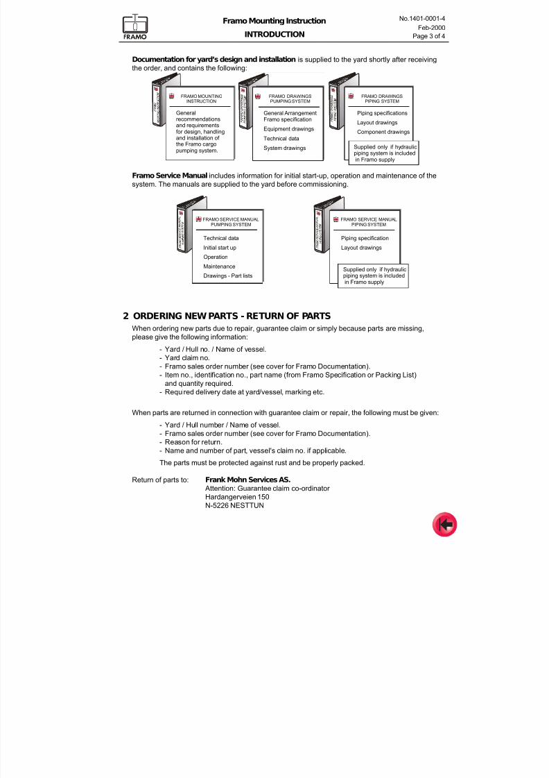
Documentation for yard’s design and installation is supplied to the yard shortly after receiving
the order, and contains the following:
Framo Service Manual includes information for initial start-up, operation and maintenance of the
system. The manuals are supplied to the yard before commissioning.
FRAMO MOUNTINGINSTRUCTION
FRAMO DRAWINGSPUMPING SYSTEM
FRAMO DRAWINGSPIPING SYSTEM
Generalrecommendationsand requirementsfor design, handlingand installation of the Framo cargopumping system.
General ArrangementFramo specification
Equipment drawings
Technical data
System drawings
Piping specifications
Layout drawings
Component drawings
Supplied only if hydraulicpiping system is includedin Framo supply
FRAMO SERVICE MANUALPUMPING SYSTEM
FRAMO SERVICE MANUALPIPING SYSTEM
Technical data
Initial start up
Operation
Maintenance
Drawings - Part lists
Piping specification
Layout drawings
Supplied only if hydraulicpiping system is includedin Framo supply
2 ORDERING NEW PARTS - RETURN OF PARTS
When ordering new parts due to repair, guarantee claim or simply because parts are missing,
please give the following information:
- Yard / Hull no. / Name of vessel.
- Yard claim no.
- Framo sales order number (see cover for Framo Documentation).
- Item no., identification no., part name (from Framo Specification or Packing List)
and quantity required.- Required delivery date at yard/vessel, marking etc.
When parts are returned in connection with guarantee claim or repair, the following must be given:
- Yard / Hull number / Name of vessel.
- Framo sales order number (see cover for Framo Documentation).
- Reason for return.
- Name and number of part, vessel's claim no. if applicable.
The parts must be protected against rust and be properly packed.
Return of parts to: Frank Mohn Services AS. Attention: Guarantee claim co-ordinator
Hardangerveien 150
N-5226 NESTTUN
7/16/2019 Pompe Framo
http://slidepdf.com/reader/full/pompe-framo 5/175
Framo Mounting Instruction
INTRODUCTION
No.1401-0001-4
Feb-2000
Page 4 of 4
3 ADDRESSES
Sales Department
FRANK MOHN A/S Telephone: (47) 55 99 90 00
P.O. Box 98 Slåtthaug Telefax: (47) 55 99 93 80
N-5851 BERGEN, Norway E-Mail: [email protected]
Internet: www.framo.com
Project Management
The Project Department is totally responsible for every order on Framo Cargo Pumping
System. To handle each individual order, a Project manager in the Project Department will be
appointed. The Project manager is the main contact during the project- and installation period.
If the order contains hydraulic- or cargo piping, this part of the order will be handled by thePiping Department which will handle the engineering, documentation and supply of piping.
A Project engineer in the Piping Department will be appointed accordingly.
Checking of the installation during commissioning and follow-up during the guaratee period is
handled by the Service Department. A Project engineer at the Service Department will be
appointed, and will be the main contact during the commissioning and guarantee period.
Contact addresses:
Project DepartmentFRANK MOHN FUSA AS Telephone: (47) 55 99 96 00
P.O. Box 10 Telefax: (47) 55 99 97 84
N-5641 FUSA, Norway E-Mail: [email protected]
Piping Department
FRANK MOHN FLATØY A/S Telephone: (47) 55 99 94 00
Flatøy Telefax: (47) 55 99 95 84
N-5918 FREKHAUG, Norway E-Mail: [email protected]
Service Department
FRANK MOHN SERVICES AS Telephone: (47) 55 99 92 00
P.O. Box 44 Slåtthaug After 1600 hrs.: (47) 90 99 00 06
N-5851 BERGEN, Norway Telefax: (47) 55 99 93 82
E-Mail: [email protected]
7/16/2019 Pompe Framo
http://slidepdf.com/reader/full/pompe-framo 6/175
Framo
Mounting Instruction
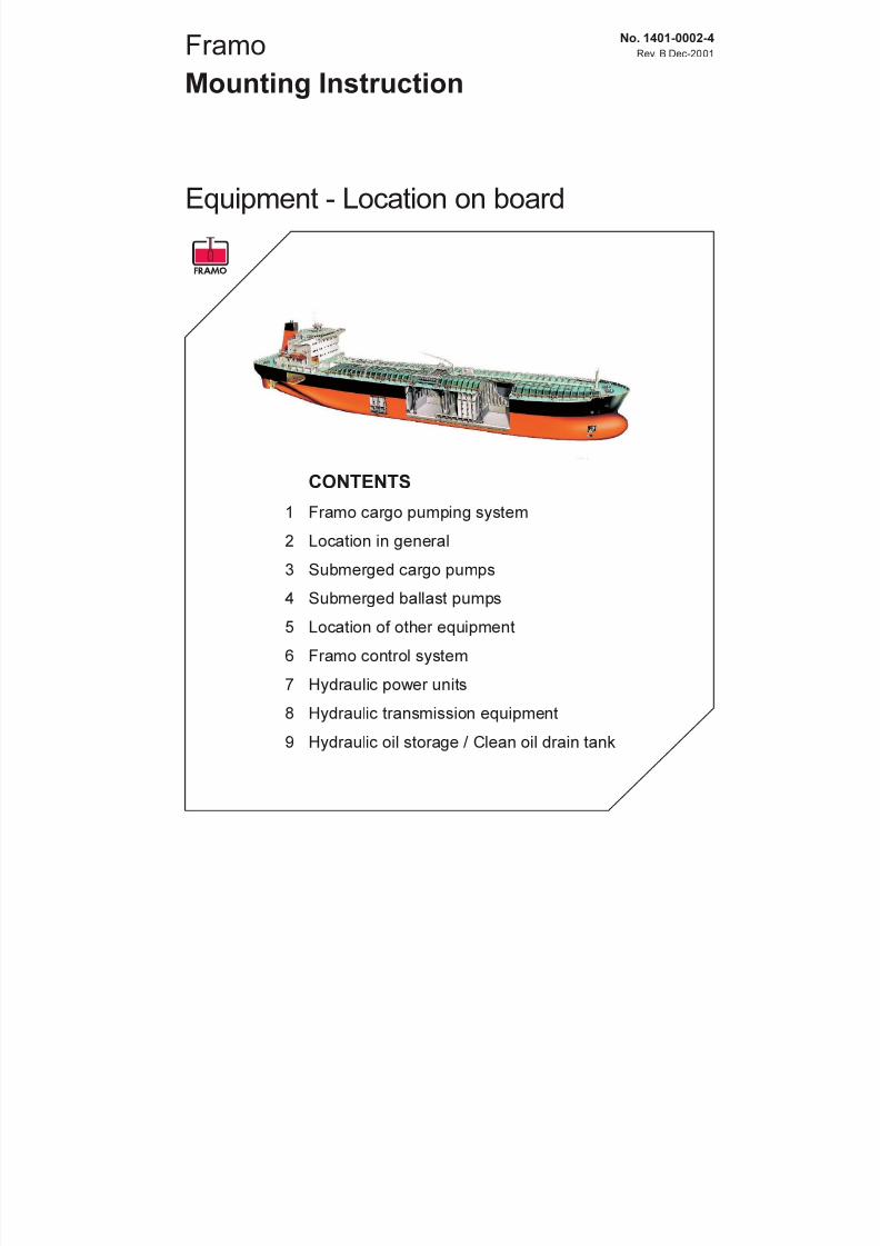
Equipment - Location on board
No. 1401-0002-4
Rev. B Dec-2001
CONTENTS
1 Framo cargo pumping system
2 Location in general
3 Submerged cargo pumps
4 Submerged ballast pumps
5 Location of other equipment
6 Framo control system
7 Hydraulic power units
8 Hydraulic transmission equipment
9 Hydraulic oil storage / Clean oil drain tank
7/16/2019 Pompe Framo
http://slidepdf.com/reader/full/pompe-framo 7/175
Framo Mounting Instruction
EQUIPMENT - LOCATION ON BOARD
No.1401-0002-4
Rev.B Dec-2001
Page 2 of 8
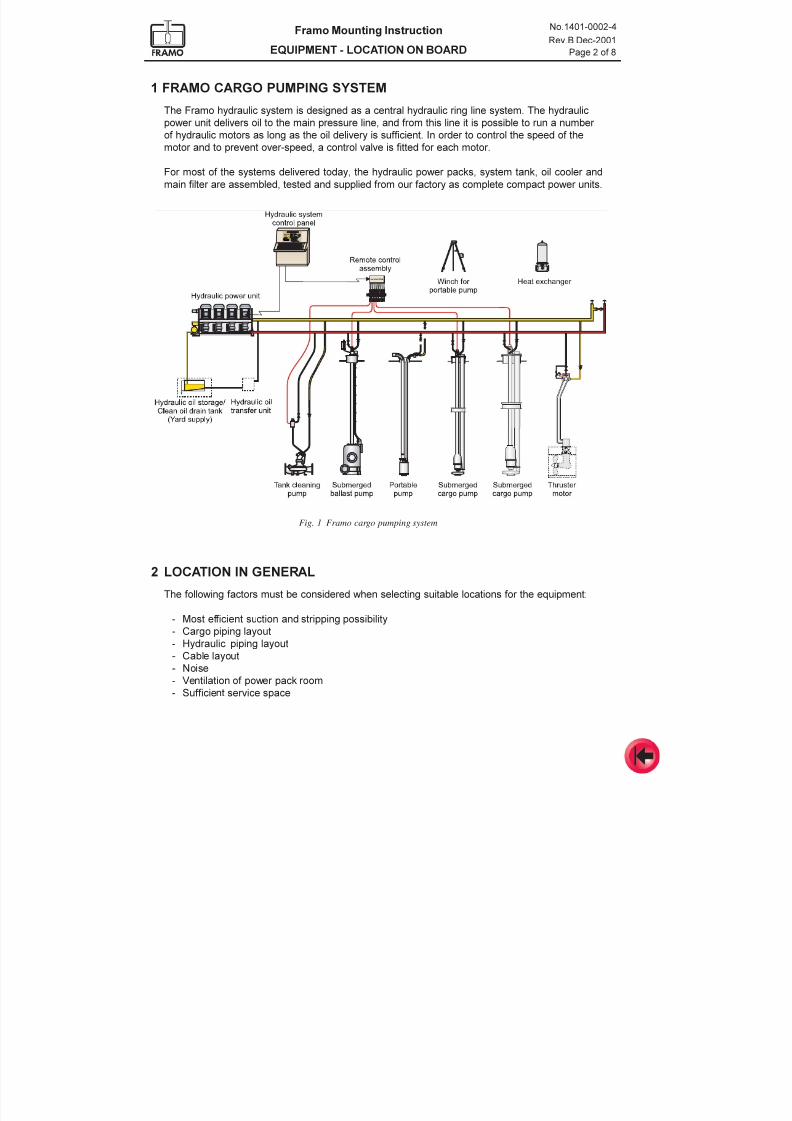
The Framo hydraulic system is designed as a central hydraulic ring line system. The hydraulic
power unit delivers oil to the main pressure line, and from this line it is possible to run a number
of hydraulic motors as long as the oil delivery is sufficient. In order to control the speed of themotor and to prevent over-speed, a control valve is fitted for each motor.
For most of the systems delivered today, the hydraulic power packs, system tank, oil cooler and
main filter are assembled, tested and supplied from our factory as complete compact power units.
1 FRAMO CARGO PUMPING SYSTEM
Fig. 1 Framo cargo pumping system
2 LOCATION IN GENERAL
The following factors must be considered when selecting suitable locations for the equipment:
- Most efficient suction and stripping possibility
- Cargo piping layout
- Hydraulic piping layout
- Cable layout
- Noise
- Ventilation of power pack room
- Sufficient service space
7/16/2019 Pompe Framo
http://slidepdf.com/reader/full/pompe-framo 8/175
Framo Mounting Instruction
EQUIPMENT - LOCATION ON BOARD
No.1401-0002-4
Rev.B Dec-2001
Page 3 of 8
C pipestackL
Bulkhe
ad
Cargo valve
Cargo pipeFlexible clamp
Location of bracketsfor lower support ring
Position of suction well
Clearance betweensuction bellmouth and well
Pipestack parallelto bulkhead
High pressure pipe
Service valves
Low pressure pipe
Local control valve
Exhaust trap
Stripping pipe
Valve for drop line
Drop line
Location of bracketfor intermediate support
Stripping valve
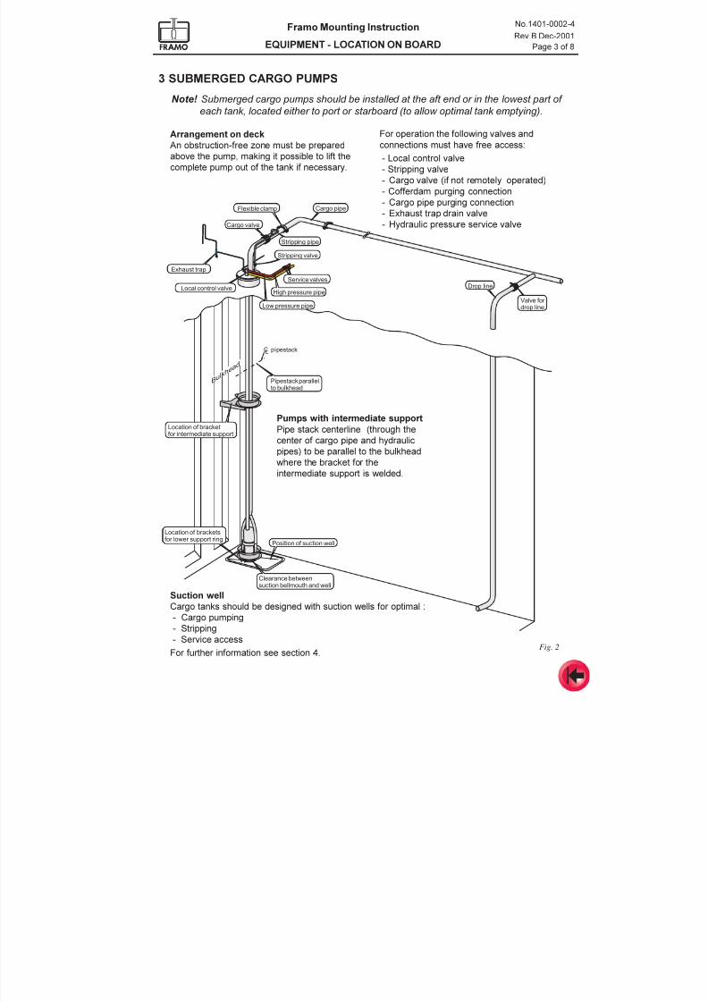
3 SUBMERGED CARGO PUMPS
Note! Submerged cargo pumps should be installed at the aft end or in the lowest part of
each tank, located either to port or starboard (to allow optimal tank emptying).
Fig. 2
Arrangement on deck
An obstruction-free zone must be prepared
above the pump, making it possible to lift the
complete pump out of the tank if necessary.
For operation the following valves and
connections must have free access:
- Local control valve
- Stripping valve
- Cargo valve (if not remotely operated)
- Cofferdam purging connection
- Cargo pipe purging connection
- Exhaust trap drain valve
- Hydraulic pressure service valve
Pumps with intermediate support
Pipe stack centerline (through the
center of cargo pipe and hydraulic
pipes) to be parallel to the bulkhead
where the bracket for the
intermediate support is welded.
Suction well
Cargo tanks should be designed with suction wells for optimal :
- Cargo pumping- Stripping
- Service access
For further information see section 4.
7/16/2019 Pompe Framo
http://slidepdf.com/reader/full/pompe-framo 9/175
Framo Mounting Instruction
EQUIPMENT - LOCATION ON BOARD
No.1401-0002-4
Rev.B Dec-2001
Page 4 of 8
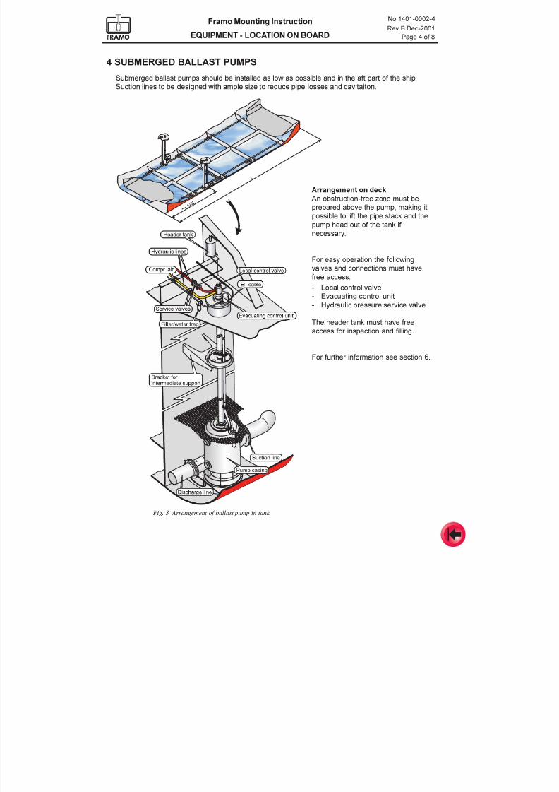
4 SUBMERGED BALLAST PUMPS
Submerged ballast pumps should be installed as low as possible and in the aft part of the ship.
Suction lines to be designed with ample size to reduce pipe losses and cavitaiton.
Arrangement on deck
An obstruction-free zone must be
prepared above the pump, making it
possible to lift the pipe stack and the
pump head out of the tank if
necessary.
For easy operation the following
valves and connections must have
free access:
- Local control valve
- Evacuating control unit- Hydraulic pressure service valve
The header tank must have free
access for inspection and filling.
For further information see section 6.
Fig. 3 Arrangement of ballast pump in tank
7/16/2019 Pompe Framo
http://slidepdf.com/reader/full/pompe-framo 10/175
Framo Mounting Instruction
EQUIPMENT - LOCATION ON BOARD
No.1401-0002-4
Rev.B Dec-2001
Page 5 of 8
5 LOCATION OF OTHER EQUIPMENT
- Hydraulic driven pumps on deck, see section 7.
- Hydraulic driven thruster motor, see section 11.
- Deck mounted cargo heat exchangers, see section 12.- Submerged cargo heat exchangers, see section 13.
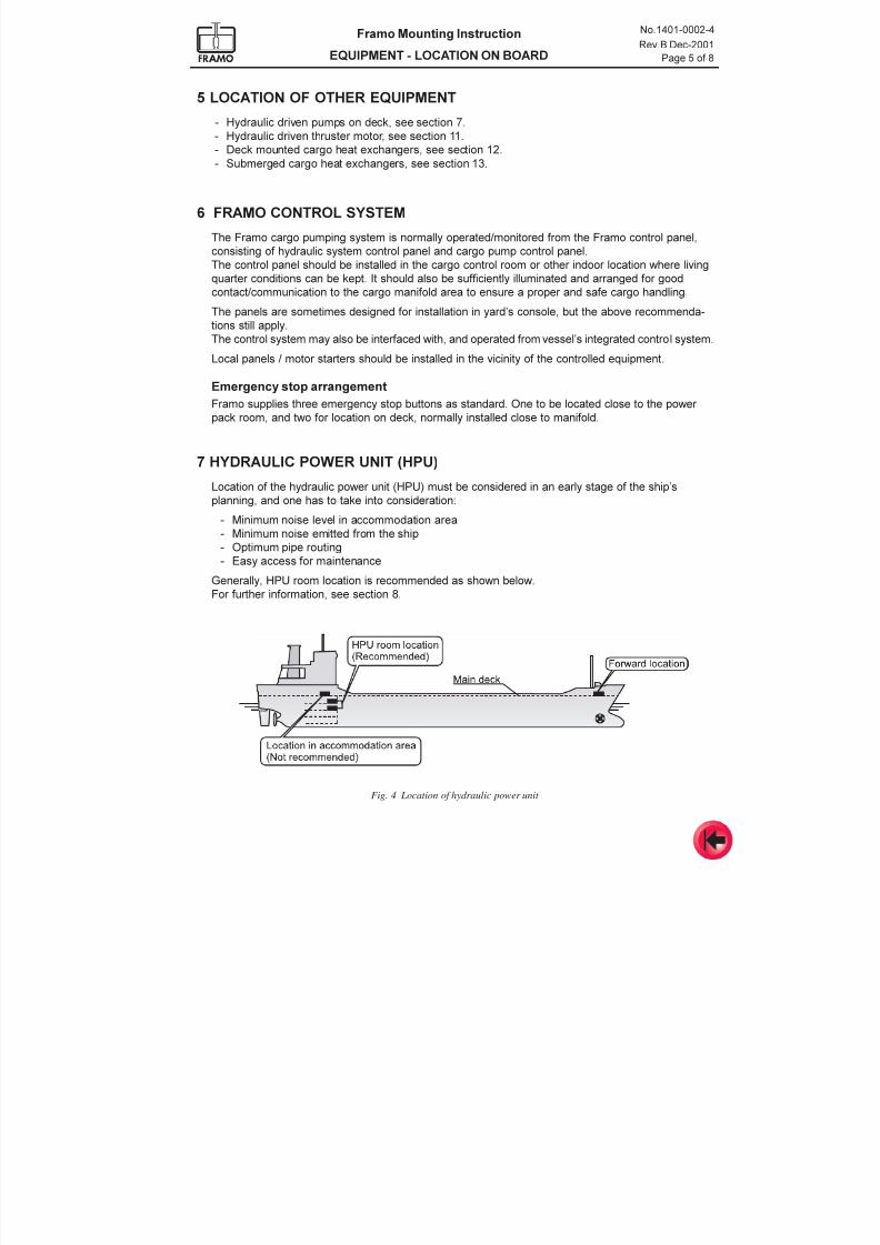
7 HYDRAULIC POWER UNIT (HPU)
Location of the hydraulic power unit (HPU) must be considered in an early stage of the ships
planning, and one has to take into consideration:
- Minimum noise level in accommodation area
- Minimum noise emitted from the ship
- Optimum pipe routing
- Easy access for maintenance
Generally, HPU room location is recommended as shown below.
For further information, see section 8.
6 FRAMO CONTROL SYSTEM
The Framo cargo pumping system is normally operated/monitored from the Framo control panel,
consisting of hydraulic system control panel and cargo pump control panel.
The control panel should be installed in the cargo control room or other indoor location where living
quarter conditions can be kept. It should also be sufficiently illuminated and arranged for good
contact/communication to the cargo manifold area to ensure a proper and safe cargo handling.
The panels are sometimes designed for installation in yards console, but the above recommenda-tions still apply.
The control system may also be interfaced with, and operated from vessels integrated control system.
Local panels / motor starters should be installed in the vicinity of the controlled equipment.
Emergency stop arrangement
Framo supplies three emergency stop buttons as standard. One to be located close to the power
pack room, and two for location on deck, normally installed close to manifold.
Fig. 4 Location of hydraulic power unit
7/16/2019 Pompe Framo
http://slidepdf.com/reader/full/pompe-framo 11/175
Framo Mounting Instruction
EQUIPMENT - LOCATION ON BOARD
No.1401-0002-4
Rev.B Dec-2001
Page 6 of 8
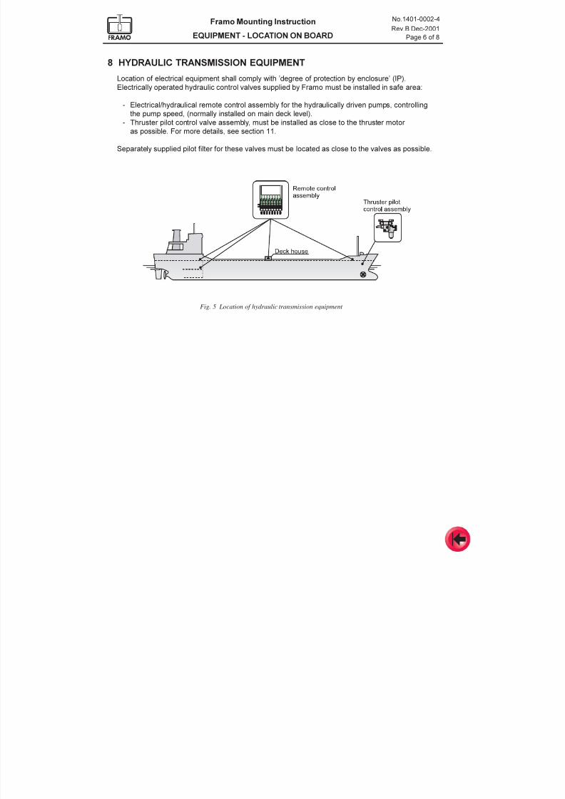
8 HYDRAULIC TRANSMISSION EQUIPMENT
Location of electrical equipment shall comply with degree of protection by enclosure (IP).
Electrically operated hydraulic control valves supplied by Framo must be installed in safe area:
- Electrical/hydraulical remote control assembly for the hydraulically driven pumps, controlling
the pump speed, (normally installed on main deck level).
- Thruster pilot control valve assembly, must be installed as close to the thruster motor
as possible. For more details, see section 11.
Separately supplied pilot filter for these valves must be located as close to the valves as possible.
Fig. 5 Location of hydraulic transmission equipment
7/16/2019 Pompe Framo
http://slidepdf.com/reader/full/pompe-framo 12/175
Framo Mounting Instruction
EQUIPMENT - LOCATION ON BOARD
No.1401-0002-4
Rev.B Dec-2001
Page 7 of 8
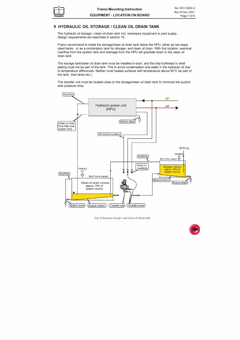
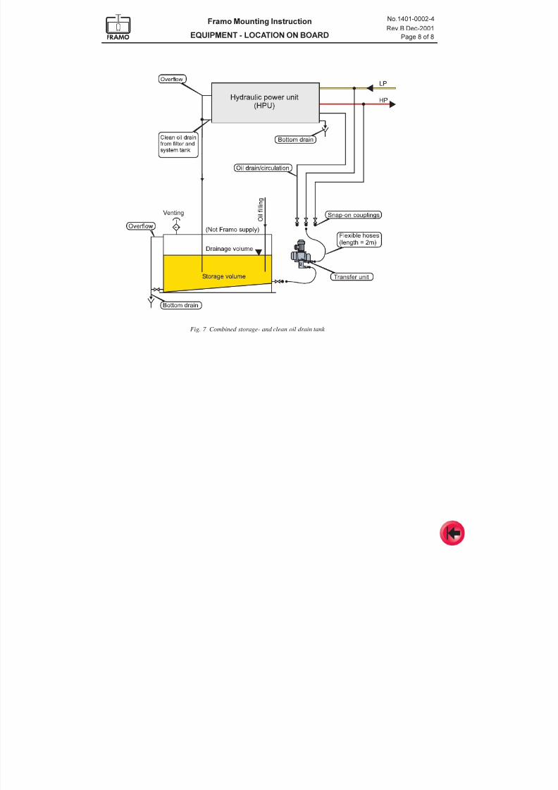
9 HYDRAULIC OIL STORAGE / CLEAN OIL DRAIN TANK
The hydraulic oil storage / clean oil drain tank incl. necessary equipment is yard supply.
Design requirements are described in section 10.
Framo recommend to install the storage/clean oil drain tank below the HPU, either as two sepa-
rated tanks, or as a combination tank for storage- and clean oil drain. With this location, eventual
overflow from the system tank and drainage from the HPU will gravitate down to the clean oil
drain tank.
The storage tank/clean oil drain tank must be installed in-door, and the ship bulkhead or shell
plating must not be part of the tank. This to avoid condensation and water in the hydraulic oil due
to temperature differences. Neither must heated surfaces with temperature above 60°C be part of
the tank, (fuel tanks etc.).
The transfer unit must be located close to the storage/clean oil drain tank to minimise the suction
side pressure drop.
Fig. 6 Separate storage- and clean oil drain tank
7/16/2019 Pompe Framo
http://slidepdf.com/reader/full/pompe-framo 13/175
Framo Mounting Instruction
EQUIPMENT - LOCATION ON BOARD
No.1401-0002-4
Rev.B Dec-2001
Page 8 of 8
Fig. 7 Combined storage- and clean oil drain tank
7/16/2019 Pompe Framo
http://slidepdf.com/reader/full/pompe-framo 14/175
Framo
Mounting Instruction
Equipment handling - Storage at yard
No. 1401-0003-4
Feb-2000
1 Goods receival
2 Preservation, packing and marking
3 Handling of Framo equipment3.1 Handling of power units
3.2 Handling of submerged cargo- and ballast pumps
3.3 Handling of heat exchanger
3.4 Handling of portable equipment
4 Storage at yard4.1 Storage in dry and clean conditions
4.2 Warehouse storage
4.3 Outdoor storage
CONTENTS
7/16/2019 Pompe Framo
http://slidepdf.com/reader/full/pompe-framo 15/175
Framo Mounting Instruction
EQUIPMENT HANDLING - STORAGE AT YARD
No.1401-0003-4
Feb-2000
Page 2 of 9
1 GOODS RECEIVAL
Immediately after receipt of equipment, please check that the supply corresponds to the packing
list. Any missing items must be reported to Frank Mohn Fusa AS without delay.
The equipment should be carefully inspected for transportation damage. Damages should be
recorded, photographed, witnessed and reported to carriers and to Frank Mohn Fusa AS.
2 PRESERVATION, PACKING AND MARKING
Preservation
Stainless steel components are pickled, cleaned and ready for installation.
Mild steel components are protected against corrosion by means of priming or painting outside andprotecting oil inside. The preserving oil is mixable with the hydraulic oil, and will give sufficient
protection for about 1 year provided that the blank flanges are kept on.
Un-primed mild steel seal faces are normally protected by a removable corrosion preventive
coating (Tectyl).
Packing and marking
Generally most of the Framo components are packed in plastic-covered wooden boxes.
Electrical equipment
like electrical cabinets, starters and control panels have also silica gel inside for protection againstmoisture. Ventilation openings and cable entrances on electrical motors are in addition covered by
fire resistant tarpaulin.
Power units
are normally covered by plastics and shipped in containers. If they are shipped on open flat racks,
they are covered by light tarpaulin (reinforced plastic) in addition to the plastics.
Submerged cargo- and ballast pumps
are supported by special wooden racks. If the length is more than 14 meters they are split in two
sections to simplify handling and transport.
Smaller pump units, deck trunks etc.
are fastened on pallets and covered by plastics.
The deck trunks seal faces are protected by plywood.
Prefabricated pipes
are packed on transport racks with wooden frames and covered by plastics.
7/16/2019 Pompe Framo
http://slidepdf.com/reader/full/pompe-framo 16/175
Framo Mounting Instruction
EQUIPMENT HANDLING - STORAGE AT YARD
No.1401-0003-4
Feb-2000
Page 3 of 9
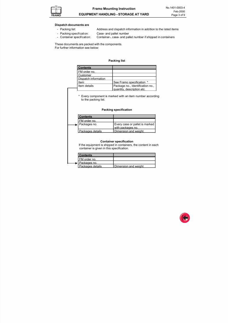
Packing list
Contents
FM order no.
Customer
Dispatch informationItem See Framo specification *
Item details Package no., Identification no.,quantity, description etc.
* Every component is marked with an item number accordingto the packing list.
Packing specification
Contents
FM order no.Packages no. Every case or pallet is marked
with packages no.
Packages details Dimension and weight
Container specificationIf the equipment is shipped in containers, the content in eachcontainer is given in this specification.
Contents
FM order no.Packages no.Packages details Dimension and weight
Dispatch documents are
- Packing list: Address and dispatch information in addition to the listed items
- Packing specification: Case- and pallet number
- Container specification: Container-, case- and pallet number if shipped in containers
These documents are packed with the components.
For further information see below:
7/16/2019 Pompe Framo
http://slidepdf.com/reader/full/pompe-framo 17/175
Framo Mounting Instruction
EQUIPMENT HANDLING - STORAGE AT YARD
No.1401-0003-4
Feb-2000
Page 4 of 9
3 HANDLING OF FRAMO EQUIPMENT
Even if the components used in Framo Cargo Pumping Systems are of rigid construction, they
should always be handled with care. Never step or climb on the equipment.
Be careful not to destroy or remove the transport protection before final installation onboard.Lifting, lowering and handling in general should be done slowly and carefully to avoid damage to
motor bearings caused by vibration and shocks.
Note! Handling information given on the package must be strictly followed.
Stainless steel components must not be in direct contact with mild steel.
3.1 Handling of power units
General info
The power units are equipped with 4 lifting lugs. All of them must be used when lifting. Normally, a
lifting device with 4 slings of equal length can be used to lift the power unit. Avoid contact between
exposed parts of the power unit and the lifting slings.
If special lifting tools are required, these are supplied by Framo together with the power unit.
Note! Forklift must never be used to lift the power unit.
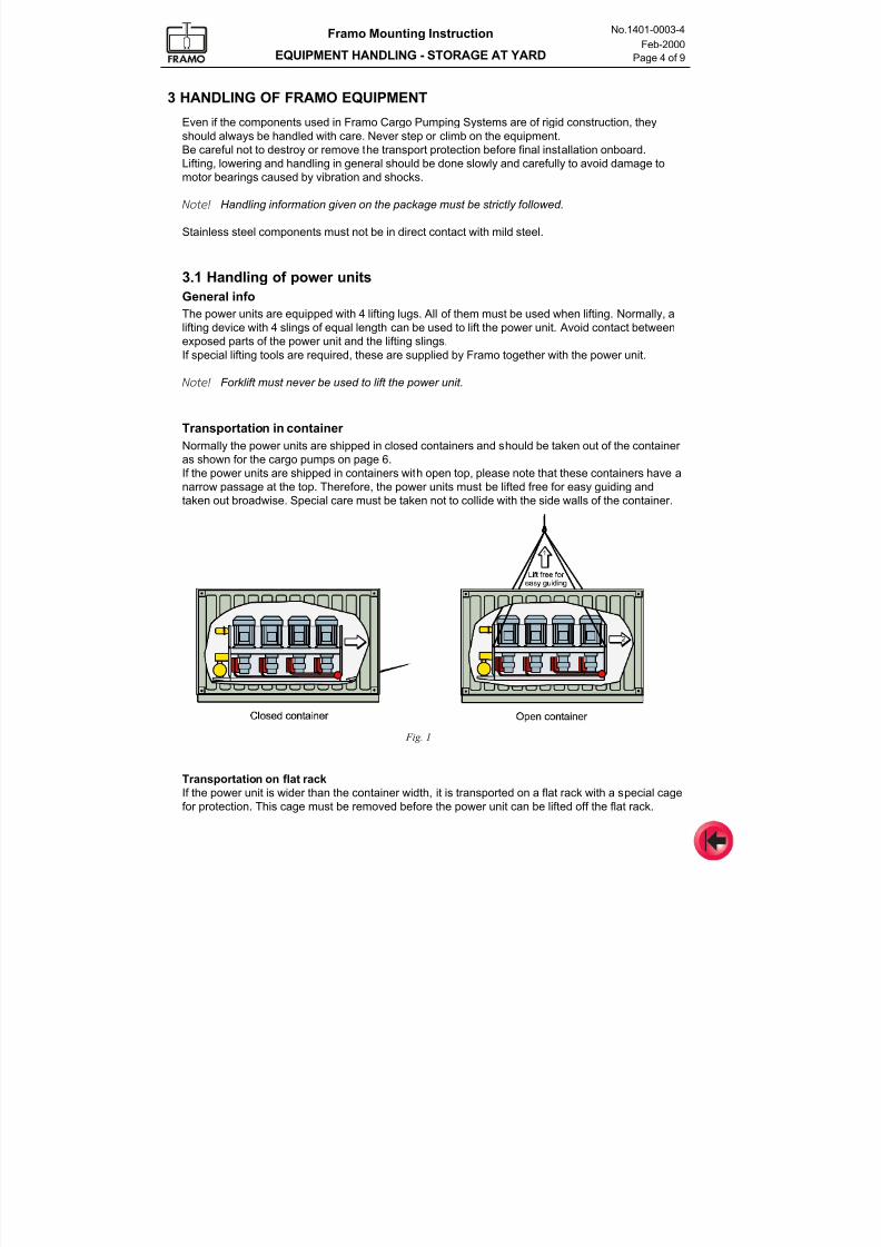
Transportation in container
Normally the power units are shipped in closed containers and should be taken out of the container
as shown for the cargo pumps on page 6.If the power units are shipped in containers with open top, please note that these containers have a
narrow passage at the top. Therefore, the power units must be lifted free for easy guiding and
taken out broadwise. Special care must be taken not to collide with the side walls of the container.
Fig. 1
Transportation on flat rack
If the power unit is wider than the container width, it is transported on a flat rack with a special cage
for protection. This cage must be removed before the power unit can be lifted off the flat rack.
7/16/2019 Pompe Framo
http://slidepdf.com/reader/full/pompe-framo 18/175
Framo Mounting Instruction
EQUIPMENT HANDLING - STORAGE AT YARD
No.1401-0003-4
Feb-2000
Page 5 of 9
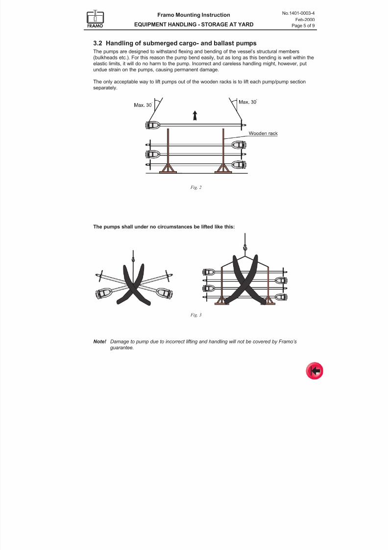
3.2 Handling of submerged cargo- and ballast pumps
The pumps are designed to withstand flexing and bending of the vessel’s structural members
(bulkheads etc.). For this reason the pump bend easily, but as long as this bending is well within the
elastic limits, it will do no harm to the pump. Incorrect and careless handling might, however, put
undue strain on the pumps, causing permanent damage.
The only acceptable way to lift pumps out of the wooden racks is to lift each pump/pump section
separately.
The pumps shall under no circumstances be lifted like this:
Note! Damage to pump due to incorrect lifting and handling will not be covered by Framo’sguarantee.
Fig. 2
Fig. 3
7/16/2019 Pompe Framo
http://slidepdf.com/reader/full/pompe-framo 19/175
Framo Mounting Instruction
EQUIPMENT HANDLING - STORAGE AT YARD
No.1401-0003-4
Feb-2000
Page 6 of 9
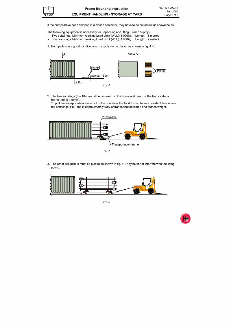
If the pumps have been shipped in a closed container, they have to be pulled out as shown below.
The following equipment is necessary for unpacking and lifting (Framo supply):
- Two softslings. Minimum working Load Limit (WLL): 5 000kg. Length: 18 meters
- Four softslings. Minimum working Load Limit (WLL): 1 000kg. Length: 2 meters
1. Four pallets in a good condition (yard supply) to be placed as shown in fig. 4 - 6.
2. The two softslings (L = 18m) must be fastened on the horizontal beam of the transportation
frame and to a forklift.
To pull the transportation frame out of the container the forklift must have a constant tension on
the softslings. Pull load is approximately 60% of transportation frame and pumps weight.
3. The other two pallets must be placed as shown in fig. 6. They must not interfere with the lifting
points.
Fig. 4
Fig. 5
Fig. 6
7/16/2019 Pompe Framo
http://slidepdf.com/reader/full/pompe-framo 20/175
Framo Mounting Instruction
EQUIPMENT HANDLING - STORAGE AT YARD
No.1401-0003-4
Feb-2000
Page 7 of 9
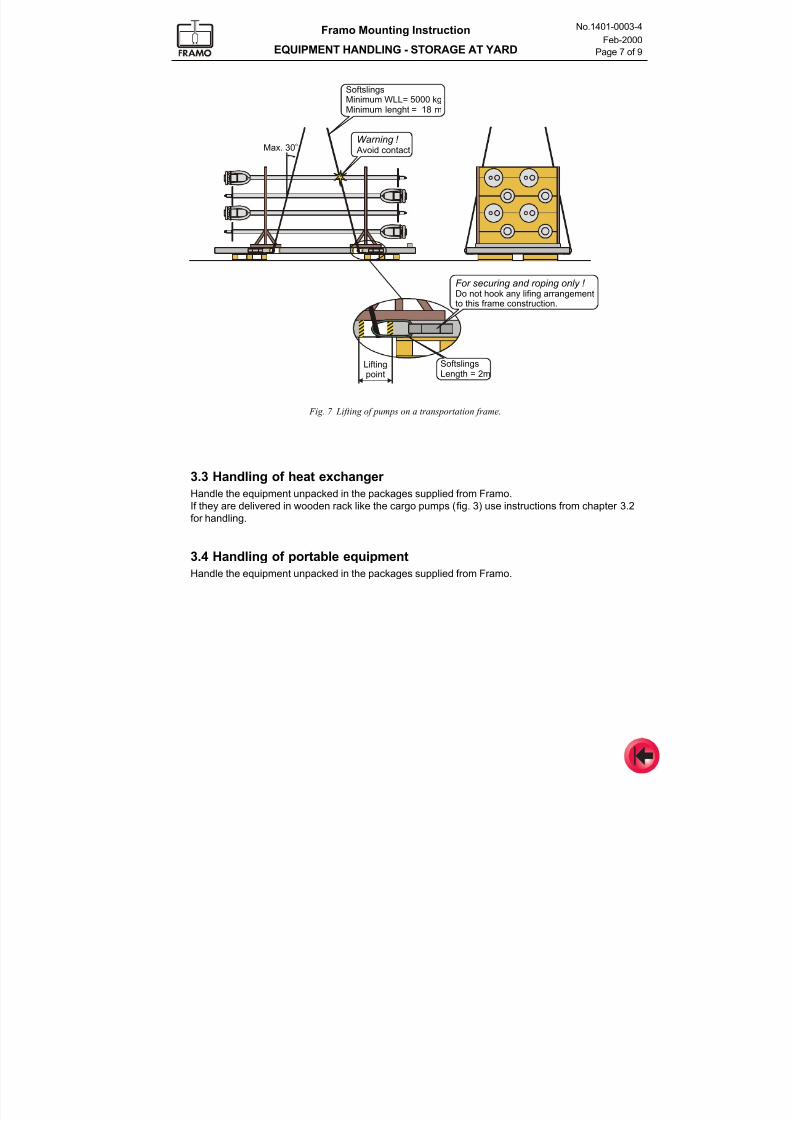
Fig. 7 Lifting of pumps on a transportation frame.
3.3 Handling of heat exchanger
Handle the equipment unpacked in the packages supplied from Framo.
If they are delivered in wooden rack like the cargo pumps (fig. 3) use instructions from chapter 3.2
for handling.
3.4 Handling of portable equipmentHandle the equipment unpacked in the packages supplied from Framo.
Max. 30o
Liftingpoint
SoftslingsMinimum WLL= 5000 kgMinimum lenght = 18 m
For securing and roping only ! Do not hook any lifing arrangementto this frame construction.
Warning ! Avoid contact
SoftslingsLength = 2m
7/16/2019 Pompe Framo
http://slidepdf.com/reader/full/pompe-framo 21/175
Framo Mounting Instruction
EQUIPMENT HANDLING - STORAGE AT YARD
No.1401-0003-4
Feb-2000
Page 8 of 9
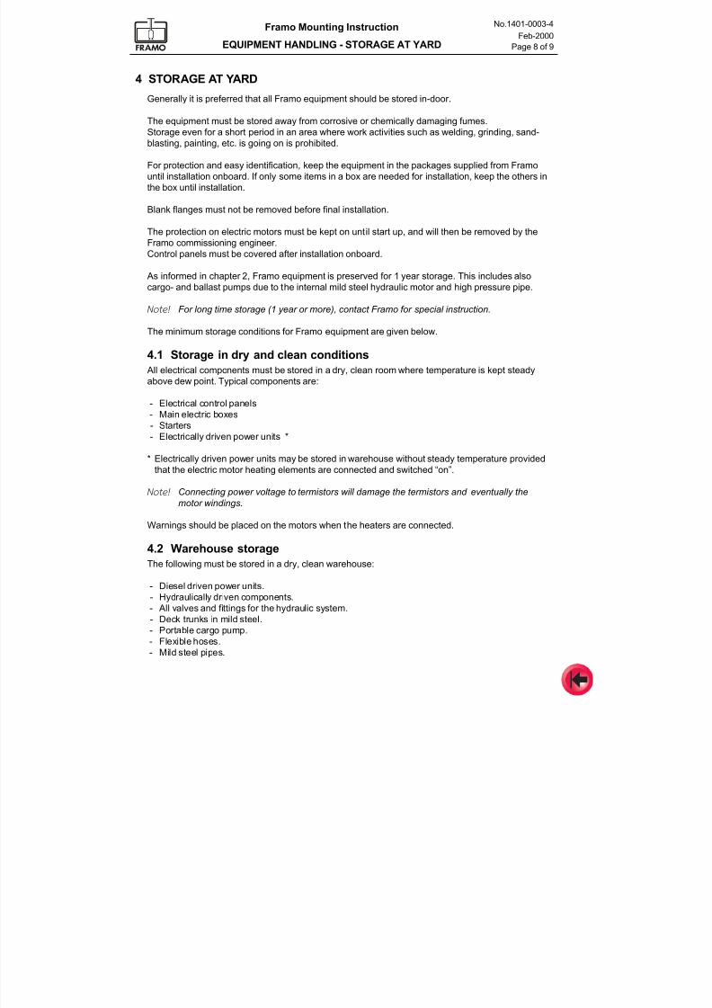
4 STORAGE AT YARD
Generally it is preferred that all Framo equipment should be stored in-door.
The equipment must be stored away from corrosive or chemically damaging fumes.Storage even for a short period in an area where work activities such as welding, grinding, sand-
blasting, painting, etc. is going on is prohibited.
For protection and easy identification, keep the equipment in the packages supplied from Framo
until installation onboard. If only some items in a box are needed for installation, keep the others in
the box until installation.
Blank flanges must not be removed before final installation.
The protection on electric motors must be kept on until start up, and will then be removed by the
Framo commissioning engineer.
Control panels must be covered after installation onboard.
As informed in chapter 2, Framo equipment is preserved for 1 year storage. This includes also
cargo- and ballast pumps due to the internal mild steel hydraulic motor and high pressure pipe.
Note! For long time storage (1 year or more), contact Framo for special instruction.
The minimum storage conditions for Framo equipment are given below.
4.1 Storage in dry and clean conditions
All electrical components must be stored in a dry, clean room where temperature is kept steadyabove dew point. Typical components are:
- Electrical control panels
- Main electric boxes
- Starters
- Electrically driven power units *
* Electrically driven power units may be stored in warehouse without steady temperature provided
that the electric motor heating elements are connected and switched “on”.
Note! Connecting power voltage to termistors will damage the termistors and eventually the
motor windings.
Warnings should be placed on the motors when the heaters are connected.
4.2 Warehouse storage
The following must be stored in a dry, clean warehouse:
- Diesel driven power units.
- Hydraulically driven components.
- All valves and fittings for the hydraulic system.
- Deck trunks in mild steel.- Portable cargo pump.
- Flexible hoses.
- Mild steel pipes.
7/16/2019 Pompe Framo
http://slidepdf.com/reader/full/pompe-framo 22/175
Framo Mounting Instruction
EQUIPMENT HANDLING - STORAGE AT YARD
No.1401-0003-4
Feb-2000
Page 9 of 9
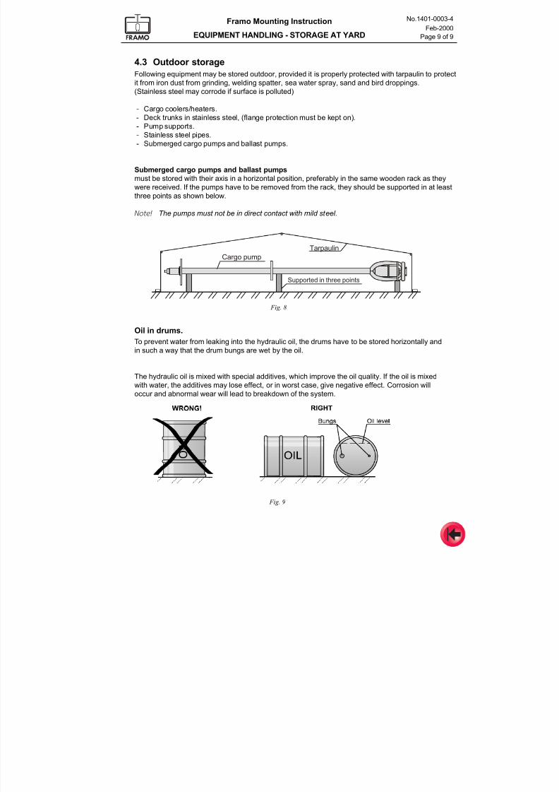
4.3 Outdoor storage
Following equipment may be stored outdoor, provided it is properly protected with tarpaulin to protect
it from iron dust from grinding, welding spatter, sea water spray, sand and bird droppings.
(Stainless steel may corrode if surface is polluted)
- Cargo coolers/heaters.
- Deck trunks in stainless steel, (flange protection must be kept on).
- Pump supports.
- Stainless steel pipes.
- Submerged cargo pumps and ballast pumps.
Submerged cargo pumps and ballast pumps
must be stored with their axis in a horizontal position, preferably in the same wooden rack as they
were received. If the pumps have to be removed from the rack, they should be supported in at least
three points as shown below.
Note! The pumps must not be in direct contact with mild steel.
Tarpaulin
Cargo pump
Supported in three points
Fig. 8
Oil in drums.
To prevent water from leaking into the hydraulic oil, the drums have to be stored horizontally and
in such a way that the drum bungs are wet by the oil.
The hydraulic oil is mixed with special additives, which improve the oil quality. If the oil is mixed
with water, the additives may lose effect, or in worst case, give negative effect. Corrosion will
occur and abnormal wear will lead to breakdown of the system.
Fig. 9
7/16/2019 Pompe Framo
http://slidepdf.com/reader/full/pompe-framo 23/175
Framo
Mounting Instruction
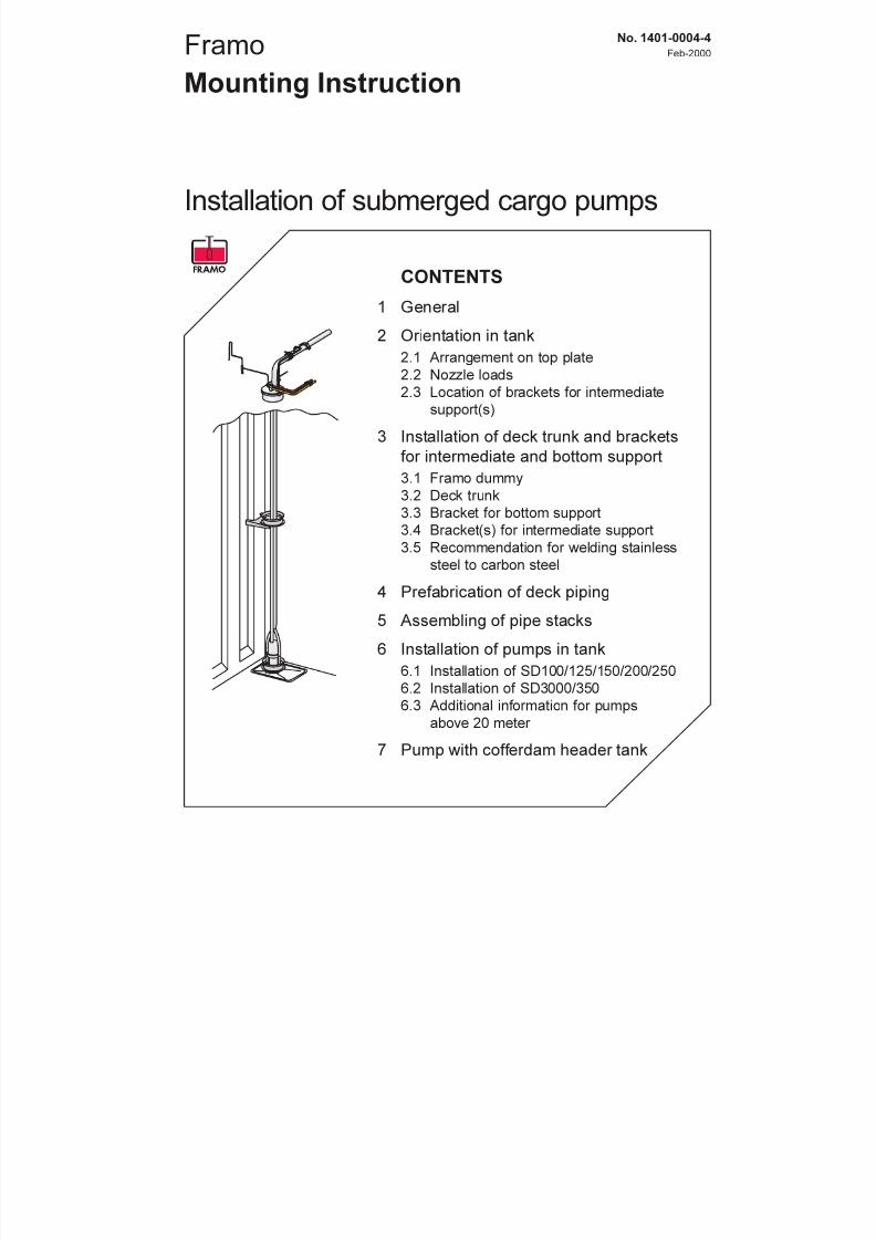
Installation of submerged cargo pumps
No. 1401-0004-4
Feb-2000
CONTENTS
1 General
2 Orientation in tank
2.1 Arrangement on top plate
2.2 Nozzle loads
2.3 Location of brackets for intermediate
support(s)
3 Installation of deck trunk and brackets
for intermediate and bottom support3.1 Framo dummy
3.2 Deck trunk
3.3 Bracket for bottom support
3.4 Bracket(s) for intermediate support
3.5 Recommendation for welding stainless
steel to carbon steel
4 Prefabrication of deck piping
5 Assembling of pipe stacks
6 Installation of pumps in tank
6.1 Installation of SD100/125/150/200/250
6.2 Installation of SD3000/350
6.3 Additional information for pumps
above 20 meter
7 Pump with cofferdam header tank
7/16/2019 Pompe Framo
http://slidepdf.com/reader/full/pompe-framo 24/175
Framo Mounting Instruction
INSTALLATION OF SUBMERGED CARGO PUMPS
No.1401-0004-4
Feb-2000
Page 2 of 22
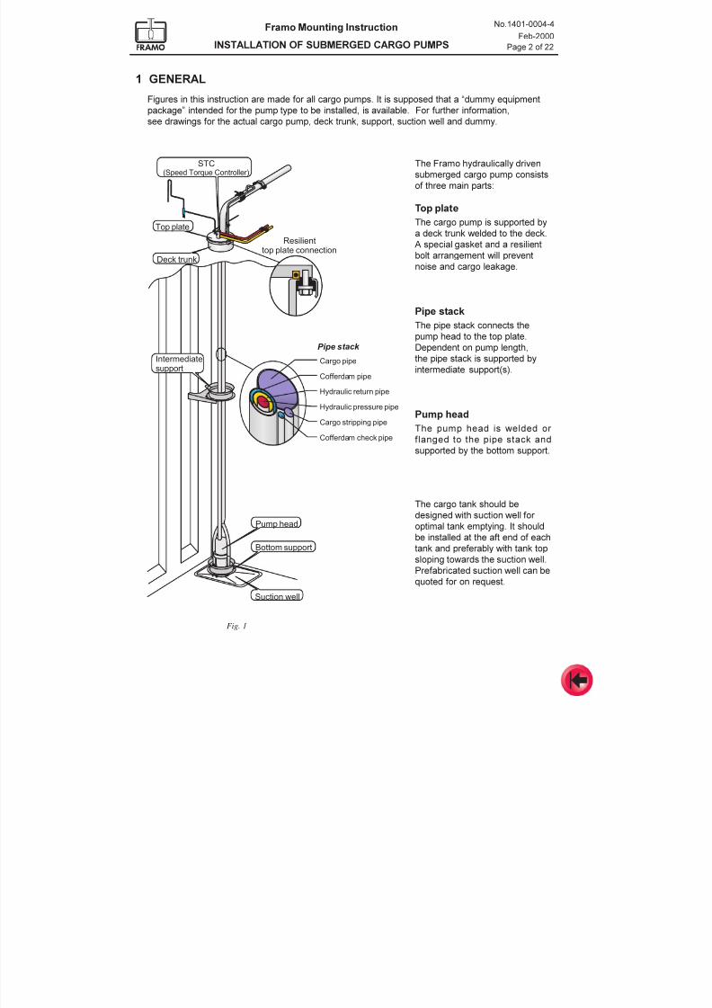
1 GENERAL
Figures in this instruction are made for all cargo pumps. It is supposed that a dummy equipment
package intended for the pump type to be installed, is available. For further information,
see drawings for the actual cargo pump, deck trunk, support, suction well and dummy.
Fig. 1
Hydraulic return pipe
Cofferdam pipe
Cargo stripping pipe
Cofferdam check pipe
Hydraulic pressure pipe
P ipe stac k
Cargo pipe
Resilient
top plate connectionDeck trunk
Top plate
Pump head
STC(Speed Torque Controller)
Intermediatesupport
Suction well
Bottom support
The Framo hydraulically driven
submerged cargo pump consists
of three main parts:
Top plate
The cargo pump is supported by
a deck trunk welded to the deck.
A special gasket and a resilientbolt arrangement will prevent
noise and cargo leakage.
Pipe stack
The pipe stack connects the
pump head to the top plate.
Dependent on pump length,
the pipe stack is supported by
intermediate support(s).
Pump head
The pump head is welded or
flanged to the pipe stack and
supported by the bottom support.
The cargo tank should be
designed with suction well for
optimal tank emptying. It should
be installed at the aft end of each
tank and preferably with tank top
sloping towards the suction well.
Prefabricated suction well can be
quoted for on request.
7/16/2019 Pompe Framo
http://slidepdf.com/reader/full/pompe-framo 25/175
Framo Mounting Instruction
INSTALLATION OF SUBMERGED CARGO PUMPS
No.1401-0004-4
Feb-2000
Page 3 of 22
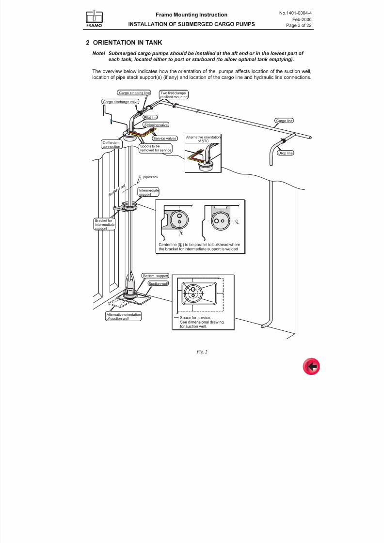
2 ORIENTATION IN TANK
Note! Submerged cargo pumps should be installed at the aft end or in the lowest part of
each tank, located either to port or starboard (to allow optimal tank emptying).
The overview below indicates how the orientation of the pumps affects location of the suction well,
location of pipe stack support(s) (if any) and location of the cargo line and hydraulic line connections.
Fig. 2
Drop line
Cargo line
Cargo stripping line
Pilot line
Stripping valve
Intermediatesupport
Bottom support
Alternative orientationof suction well Space for service.
See dimensional drawingfor suction well.
Bracket for intermediatesupport
Suction well
C pipestackL
Bulkh
ead
CL
LCenterline (C ) to be parallel to bulkhead wherethe bracket for intermediate support is welded
CL
Cofferdamconnection
Cargo discharge valve
Spools to beremoved for service
Service valves Alternative orientationof STC
Two first clampsresilient mounted
7/16/2019 Pompe Framo
http://slidepdf.com/reader/full/pompe-framo 26/175
Framo Mounting Instruction
INSTALLATION OF SUBMERGED CARGO PUMPS
No.1401-0004-4
Feb-2000
Page 4 of 22
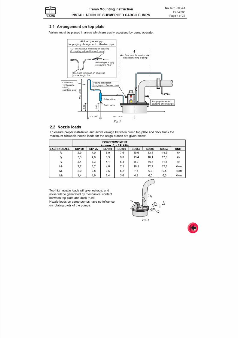
2.1 Arrangement on top plate
Valves must be placed in areas which are easily accessed by pump operator.
Fig. 3
Air/inert gas supplyfor purging of cargo and cofferdam pipe
Flex. hose with snap on couplings(normal length 2m)
Air/inert gas supplypressure 6-7 bar
1/2” closing valve with snap-on coupling(1 coupling included for each pump)
Exhaust trap
Purging connection(purging of cofferdam pipe)
Purging connection(purging of cargo pipe)
Drain valve
Cofferdamventing pipeND15,stainless steel
5 0 0
Min. 500 Min. 1500
5 0 0
M i n
. 2
0 0 0
Free area for service,installation/lifting of pump
2.2 Nozzle loads
To ensure proper installation and avoid leakage between pump top plate and deck trunk the
maximum allowable nozzle loads for the cargo pumps are given below:
Z
MF
M F
M F
ZZ
YY
X XY
X
Too high nozzle loads will give leakage, and
noise will be generated by mechanical contact
between top plate and deck trunk.
Nozzle loads on cargo pumps have no influence
on rotating parts of the pumps.
Fig. 4
)25&(6020(17DSSUR[[$3,
($&+12==/( 6' 6' 6' 6' 6' 6' 6' 81,7
) Ã
N1
) Ã
N1
) Ã
N1
0 Ã
N1P0
Ã
N1P
0 Ã
N1P
7/16/2019 Pompe Framo
http://slidepdf.com/reader/full/pompe-framo 27/175
Framo Mounting Instruction
INSTALLATION OF SUBMERGED CARGO PUMPS
No.1401-0004-4
Feb-2000
Page 5 of 22
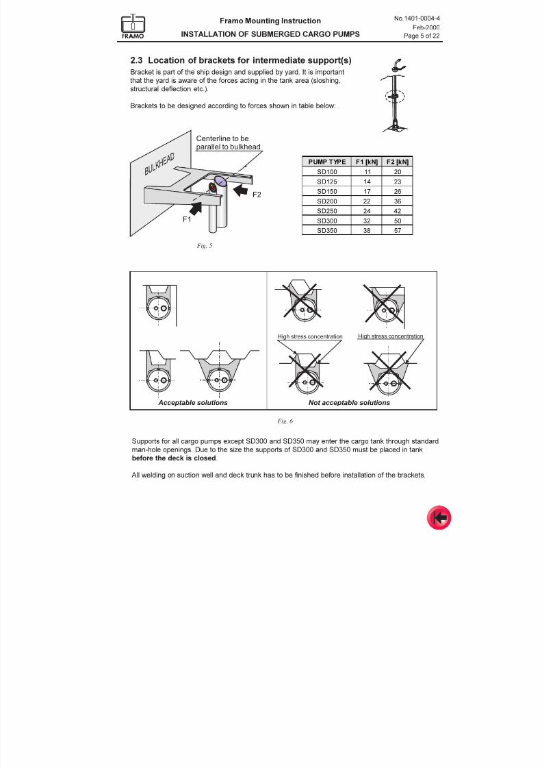
2.3 Location of brackets for intermediate support(s)
Bracket is part of the ship design and supplied by yard. It is important
that the yard is aware of the forces acting in the tank area (sloshing,
structural deflection etc.).
Brackets to be designed according to forces shown in table below:
F1
Centerline to beparallel to bulkhead
F2
High stress concentration
Not acceptable solutions Acceptable solutions
High stress concentration
38037<3( )>N1@ )>N1@
6'
6'
6'
6'
6'
6'
6'
Fig. 5
Fig. 6
Supports for all cargo pumps except SD300 and SD350 may enter the cargo tank through standard
man-hole openings. Due to the size the supports of SD300 and SD350 must be placed in tank
before the deck is closed.
All welding on suction well and deck trunk has to be finished before installation of the brackets.
7/16/2019 Pompe Framo
http://slidepdf.com/reader/full/pompe-framo 28/175
Framo Mounting Instruction
INSTALLATION OF SUBMERGED CARGO PUMPS
No.1401-0004-4
Feb-2000
Page 6 of 22
Deck trunk
Lower edgeof top plate
L
C
T B
S
A 1
A p p r o x
.
5 0
- 1 0 0 m m
A 2
H
Intermediate support
Suction wellbottom
Lower edge of intermediate support
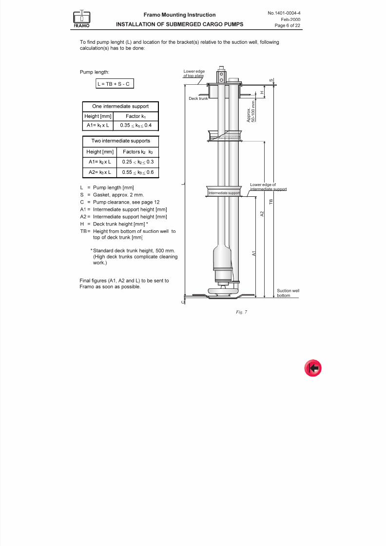
To find pump lenght (L) and location for the bracket(s) relative to the suction well, following
calculation(s) has to be done:
Pump length:
L = TB + S - C
7ZRLQWHUPHGLDWHVXSSRUWV
+HLJKW>PP@ )DFWRUVN! Ã Ã Ã Ã
N"
$N! Ã
[/ N! Ã
$N" Ã
[/ N" Ã
2QHLQWHUPHGLDWHVXSSRUW
+HLJKW>PP@ )DFWRUN
$N Ã
[/ N Ã
L = Pump length [mm]
S = Gasket, approx. 2 mm.
C = Pump clearance, see page 12 A1 = Intermediate support height [mm]
A2 = Intermediate support height [mm]
H = Deck trunk height [mm] *
TB= Height from bottom of suction well to
top of deck trunk [mm]
*Standard deck trunk height, 500 mm.
(High deck trunks complicate cleaning
work.)
Final figures (A1, A2 and L) to be sent to
Framo as soon as possible.
Fig. 7
7/16/2019 Pompe Framo
http://slidepdf.com/reader/full/pompe-framo 29/175
Framo Mounting Instruction
INSTALLATION OF SUBMERGED CARGO PUMPS
No.1401-0004-4
Feb-2000
Page 7 of 22
Support dummy
Top plate dummy
Adjustment screwsfor deck trunk height
Brackets for locationof flange connections
Measuring pipe
(one or several sets)
Support dummy
Distance plate
Measuring tape
Laser
Fig. 8a Framo dymmy
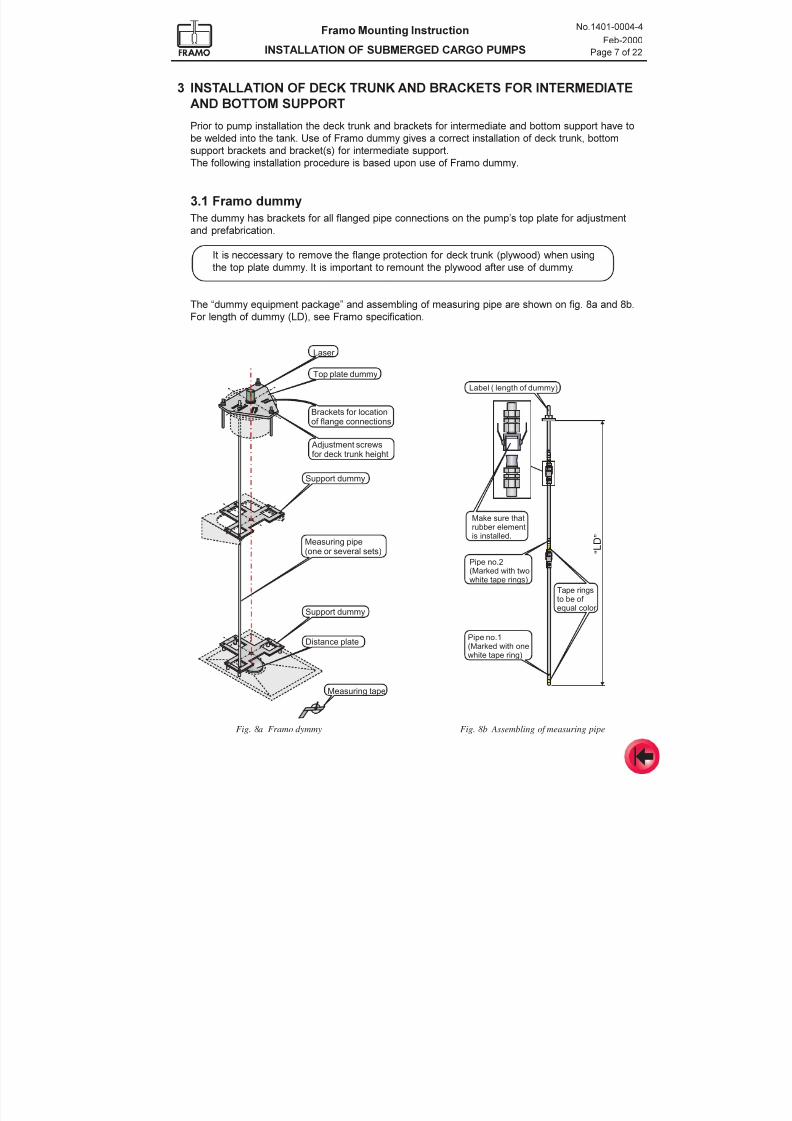
3 INSTALLATION OF DECK TRUNK AND BRACKETS FOR INTERMEDIATE
AND BOTTOM SUPPORT
Prior to pump installation the deck trunk and brackets for intermediate and bottom support have to
be welded into the tank. Use of Framo dummy gives a correct installation of deck trunk, bottomsupport brackets and bracket(s) for intermediate support.
The following installation procedure is based upon use of Framo dummy.
3.1 Framo dummy
The dummy has brackets for all flanged pipe connections on the pumps top plate for adjustment
and prefabrication.
It is neccessary to remove the flange protection for deck trunk (plywood) when using
the top plate dummy. It is important to remount the plywood after use of dummy.
The dummy equipment package and assembling of measuring pipe are shown on fig. 8a and 8b.
For length of dummy (LD), see Framo specification.
“ L D ”
Label ( length of dummy)
Make sure thatrubber elementis installed.
Pipe no.2(Marked with twowhite tape rings)
Pipe no.1(Marked with onewhite tape ring)
Tape ringsto be of equal color
Fig. 8b Assembling of measuring pipe
7/16/2019 Pompe Framo
http://slidepdf.com/reader/full/pompe-framo 30/175
Framo Mounting Instruction
INSTALLATION OF SUBMERGED CARGO PUMPS
No.1401-0004-4
Feb-2000
Page 8 of 22
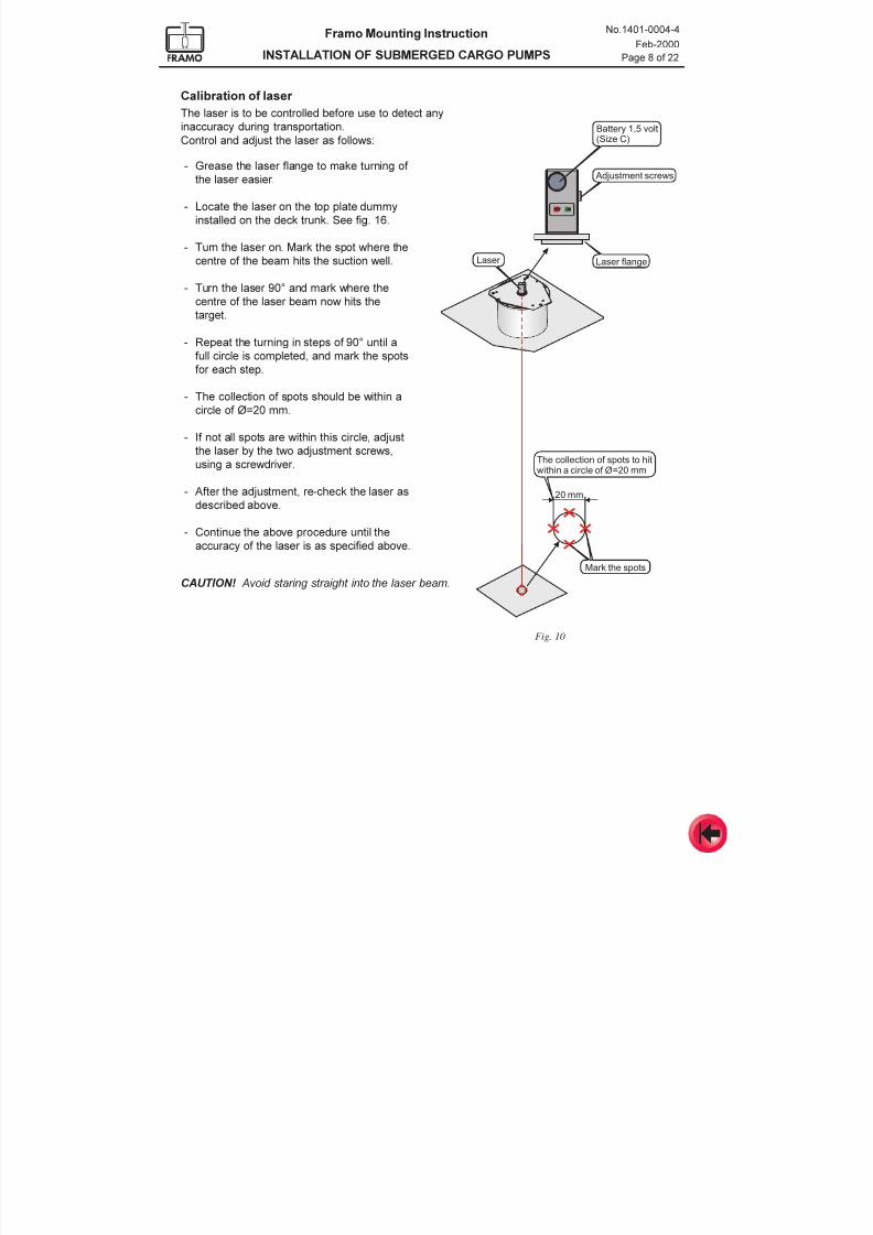
Calibration of laser
The laser is to be controlled before use to detect any
inaccuracy during transportation.
Control and adjust the laser as follows:
Fig. 10
Laser
Mark the spots
20 mm
OFF ON
Battery 1,5 volt(Size C)
Adjustment screws
Laser flange
The collection of spots to hitwithin a circle of Ø=20 mm
- Grease the laser flange to make turning of
the laser easier.
- Locate the laser on the top plate dummy
installed on the deck trunk. See fig. 16.
- Turn the laser on. Mark the spot where the
centre of the beam hits the suction well.
- Turn the laser 90° and mark where the
centre of the laser beam now hits thetarget.
- Repeat the turning in steps of 90° until a
full circle is completed, and mark the spots
for each step.
- The collection of spots should be within a
circle of Ø=20 mm.
- If not all spots are within this circle, adjust
the laser by the two adjustment screws,
using a screwdriver.
- After the adjustment, re-check the laser as
described above.
- Continue the above procedure until the
accuracy of the laser is as specified above.
CAUTION! Avoid staring straight into the laser beam.
7/16/2019 Pompe Framo
http://slidepdf.com/reader/full/pompe-framo 31/175
Framo Mounting Instruction
INSTALLATION OF SUBMERGED CARGO PUMPS
No.1401-0004-4
Feb-2000
Page 9 of 22
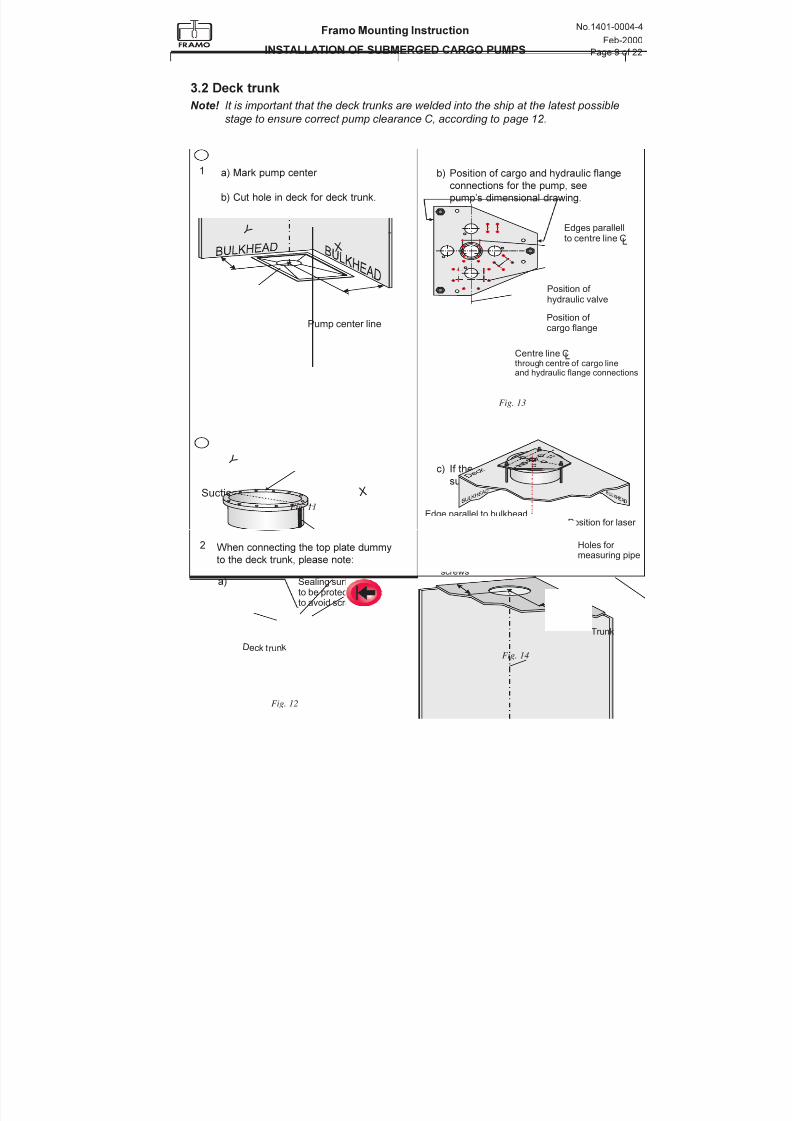
3.2 Deck trunk
Note! It is important that the deck trunks are welded into the ship at the latest possible
stage to ensure correct pump clearance C, according to page 12.
a) Mark pump center
b) Cut hole in deck for deck trunk.
X
Y
X
Y
Suction well
Pump center line
b) Position of cargo and hydraulic flange
connections for the pump, see
pumps dimensional drawing.
c) If the pump has intermediate
support(s):
Sealing surface hasto be protected in order to avoid scratches.
Welding seam must notbe orientated in ship'stransverse direction
Dec k tr un k
Position of cargo flange
Centre line Cthrough centre of cargo lineand hydraulic flange connections
Position of hydraulic valve
Edges parallellto centre line CL
L
1
2
Edge parallel to bulkheadwhere the intermediatesupport bracket shallbe welded
Adjustmentscrews
Holes for
measuring pipe
Position for laser
Trunk
Fig. 11
Fig. 12
Fig. 13
Fig. 14
a)
When connecting the top plate dummy
to the deck trunk, please note:
7/16/2019 Pompe Framo
http://slidepdf.com/reader/full/pompe-framo 32/175
Framo Mounting Instruction
INSTALLATION OF SUBMERGED CARGO PUMPS
No.1401-0004-4
Feb-2000
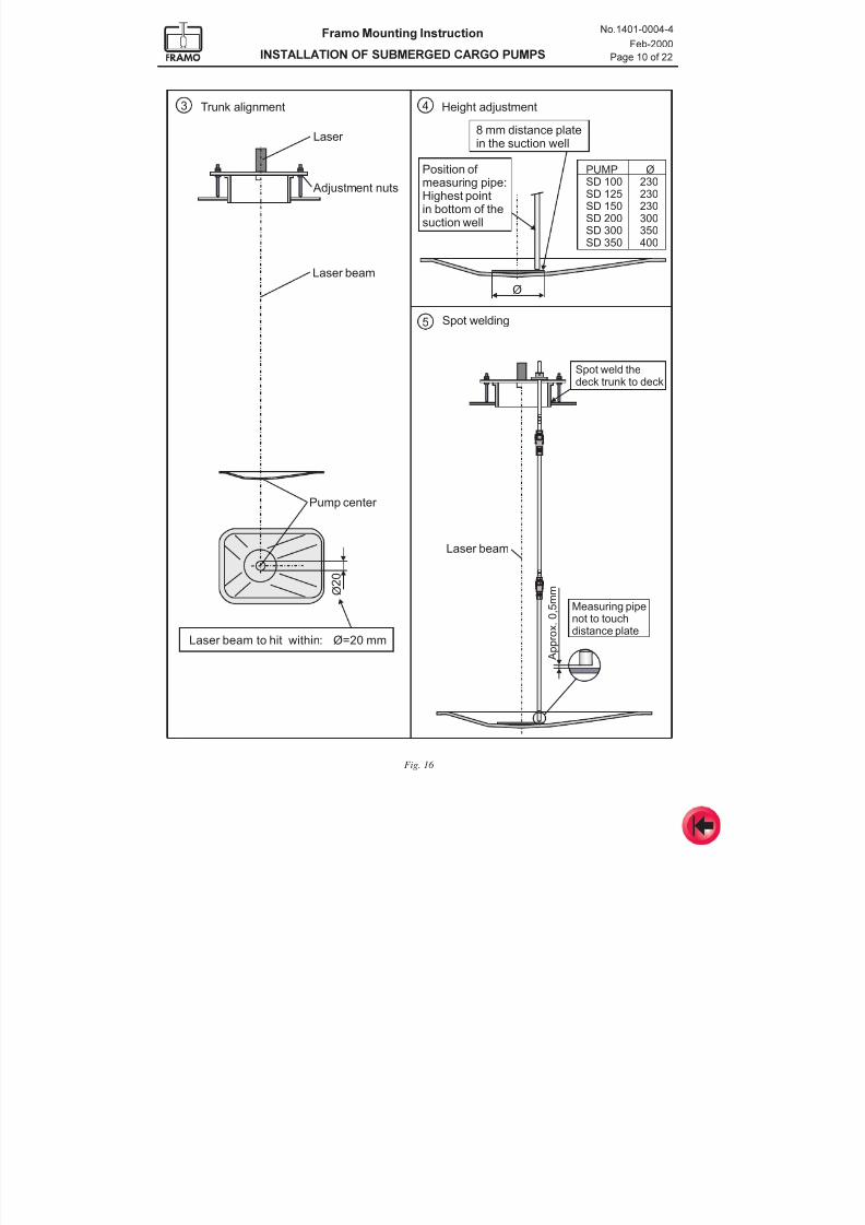
Page 10 of 22
8 mm distance platein the suction well
Position of measuring pipe:Highest pointin bottom of thesuction well
Ø
4
5
3
A p p r o x
. 0
, 5 m m
Laser beam
Spot weld thedeck trunk to deck
Measuring pipenot to touchdistance plate
Laser beam
Pump center
Laser
Trunk alignment Height adjustment
Spot welding
PUMPSD 100SD 125SD 150SD 200SD 300SD 350
Ø230230230300350400
Adjustment nuts
Laser beam to hit within: Ø=20 mm
Ø 2 0
Fig. 16
7/16/2019 Pompe Framo
http://slidepdf.com/reader/full/pompe-framo 33/175
Framo Mounting Instruction
INSTALLATION OF SUBMERGED CARGO PUMPS
No.1401-0004-4
Feb-2000
Page 11 of 22
Ruler
R
T B
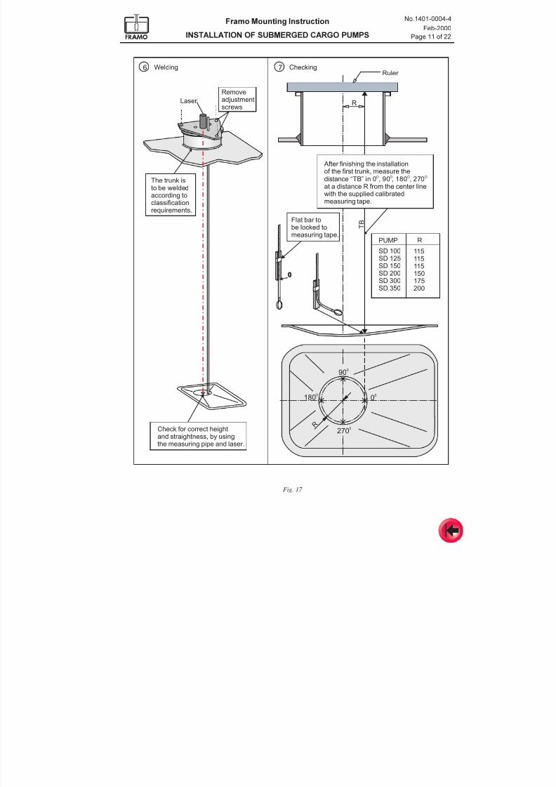
After finishing the installationof the first trunk, measure thedistance “TB” in 0 , 90 , 180 , 270at a distance R from the center line
with the supplied calibratedmeasuring tape.
O O O O
Laser
Removeadjustmentscrews
Welding Checking
PUMP
Flat bar tobe locked tomeasuring tape.
SD 100SD 125SD 150SD 200SD 300SD 350
R
R
115115115150175
200
The trunk isto be welded
according toclassificationrequirements.
Check for correct heightand straightness, by usingthe measuring pipe and laser.
6 7
1800
900
00
2700
0
Fig. 17
7/16/2019 Pompe Framo
http://slidepdf.com/reader/full/pompe-framo 34/175
Framo Mounting Instruction
INSTALLATION OF SUBMERGED CARGO PUMPS
No.1401-0004-4
Feb-2000
Page 12 of 22
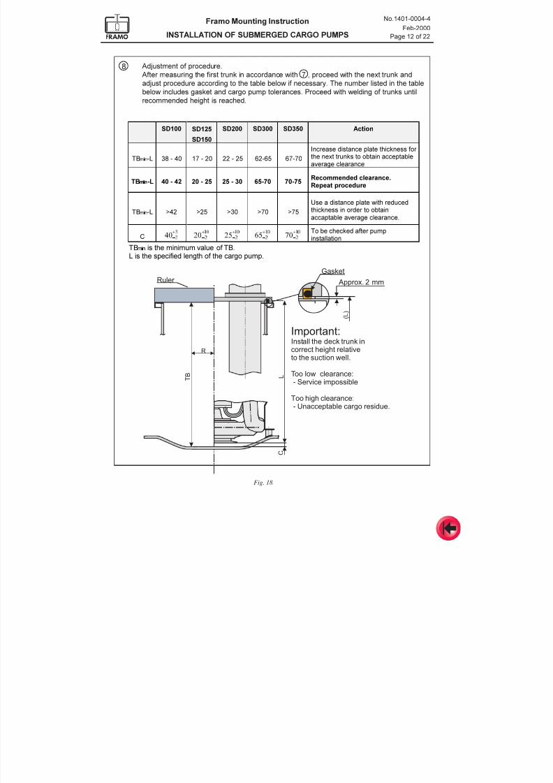
Adjustment of procedure.
After measuring the first trunk in accordance with 7 , proceed with the next trunk and
adjust procedure according to the table below if necessary. The number listed in the table
below includes gasket and cargo pump tolerances. Proceed with welding of trunks until
recommended height is reached.
6' 6'
6'
6' 6' 6' $FWLRQ
7% v
/
,QFUHDVHGLVWDQFHSODWHWKLFNQHVVIRUWKHQH[WWUXQNVWRREWDLQDFFHSWDEOHDYHUDJHFOHDUDQFH
7%P L Q
/ 5HFRPPHQGHGFOHDUDQFH5HSHDWSURFHGXUH
7% v
/ ! ! ! ! !
8VHDGLVWDQFHSODWHZLWKUHGXFHGWKLFNQHVVLQRUGHUWRREWDLQDFFDSWDEOHDYHUDJHFOHDUDQFH
&
+
-
Ã
+
-
+
-
+
-
+
-
7REHFKHFNHGDIWHUSXPSLQVWDOODWLRQ
à à à 7%P L Q
LVWKHPLQLPXPYDOXHRI7%/LVWKHVSHFLILHGOHQJWKRIWKHFDUJRSXPS
T B
Approx. 2 mm
Gasket
C
R
L
( L )
Important:Install the deck trunk incorrect height relativeto the suction well.
Too low clearance:- Service impossible
Too high clearance:- Unacceptable cargo residue.
Ruler
8
Fig. 18
7/16/2019 Pompe Framo
http://slidepdf.com/reader/full/pompe-framo 35/175
Framo Mounting Instruction
INSTALLATION OF SUBMERGED CARGO PUMPS
No.1401-0004-4
Feb-2000
Page 13 of 22
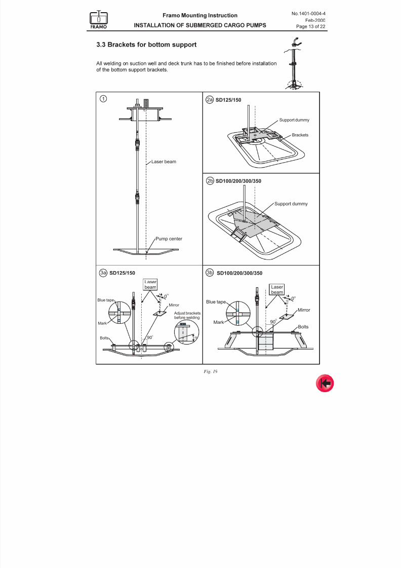
3.3 Brackets for bottom support
All welding on suction well and deck trunk has to be finished before installation
of the bottom support brackets.
1
3a 3b
2b
2a
Laser beam
Laser beam
Blue tape
Mark
Bolts
Mirror
Adjust bracketsbefore welding
90O
O0
SD125/150
SD100/200/300/350
a
Pump center
SD125/150
Support dummy
Brackets
Support dummy
Blue tape
MarkBolts
O
O
0
90
SD100/200/300/350
Laser beam
Mirror
Fig. 19
7/16/2019 Pompe Framo
http://slidepdf.com/reader/full/pompe-framo 36/175
Framo Mounting Instruction
INSTALLATION OF SUBMERGED CARGO PUMPS
No.1401-0004-4
Feb-2000
Page 14 of 22
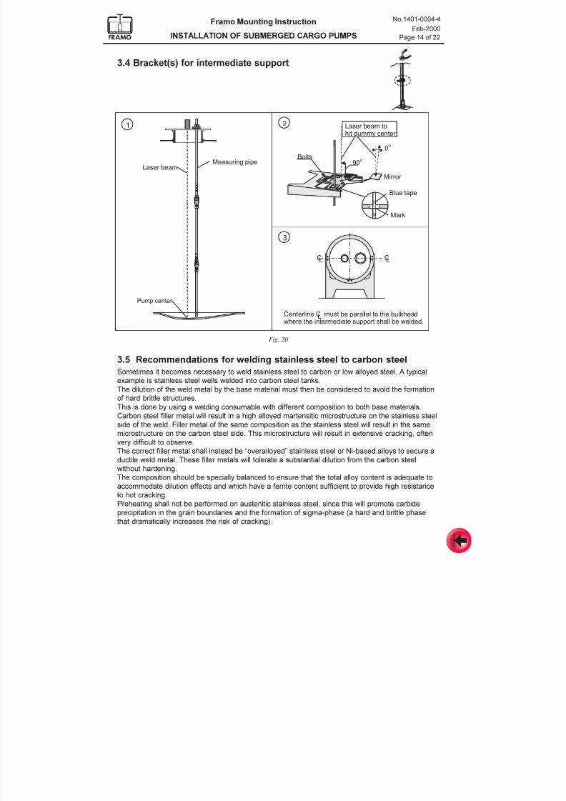
3.4 Bracket(s) for intermediate support
90O
0O
Laser beam tohit dummy center
Mirror
CC LL
Centerline C must be parallel to the bulkheadwhere the intermediate support shall be welded.
L
Laser beamMeasuring pipe
Pump center
1 2
3
Blue tape
Bolts
Mark
Fig. 20
3.5 Recommendations for welding stainless steel to carbon steel
Sometimes it becomes necessary to weld stainless steel to carbon or low alloyed steel. A typical
example is stainless steel wells welded into carbon steel tanks.
The dilution of the weld metal by the base material must then be considered to avoid the formation
of hard brittle structures.This is done by using a welding consumable with different composition to both base materials.
Carbon steel filler metal will result in a high alloyed martensitic microstructure on the stainless steel
side of the weld. Filler metal of the same composition as the stainless steel will result in the same
microstructure on the carbon steel side. This microstructure will result in extensive cracking, often
very difficult to observe.
The correct filler metal shall instead be overalloyed stainless steel or Ni-based alloys to secure a
ductile weld metal. These filler metals will tolerate a substantial dilution from the carbon steel
without hardening.
The composition should be specially balanced to ensure that the total alloy content is adequate to
accommodate dilution effects and which have a ferrite content sufficient to provide high resistance
to hot cracking.Preheating shall not be performed on austenitic stainless steel, since this will promote carbide
precipitation in the grain boundaries and the formation of sigma-phase (a hard and brittle phase
that dramatically increases the risk of cracking).
7/16/2019 Pompe Framo
http://slidepdf.com/reader/full/pompe-framo 37/175
Framo Mounting Instruction
INSTALLATION OF SUBMERGED CARGO PUMPS
No.1401-0004-4
Feb-2000
Page 15 of 22
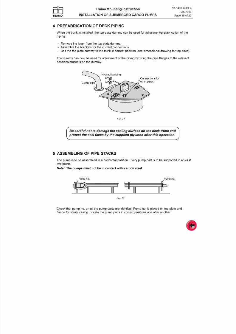
4 PREFABRICATION OF DECK PIPING
When the trunk is installed, the top plate dummy can be used for adjustment/prefabrication of the
piping.
- Remove the laser from the top plate dummy.
- Assemble the brackets for the current connections.
- Bolt the top plate dummy to the trunk in correct position (see dimensional drawing for top plate).
The dummy can now be used for adjustment of the piping by fixing the pipe flanges to the relevant
positions/brackets on the dummy.
Hydraulic piping
Connections for
other pipesCargo pipe
Be careful not to damage the sealing surface on the deck trunk and
protect the seal faces by the supplied plywood after this operation.
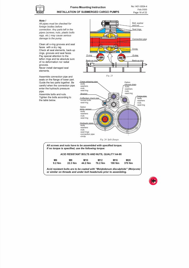
5 ASSEMBLING OF PIPE STACKS
The pump is to be assembled in a horizontal position. Every pump part is to be supported in at least
two points.Note! The pumps must not be in contact with carbon steel.
Check that pump no. on all the pump parts are identical. Pump no. is placed on top plate and
flange for volute casing. Locate the pump parts in correct positions one after another.
Pump no. Pump no.
Fig. 22
Fig. 21
7/16/2019 Pompe Framo
http://slidepdf.com/reader/full/pompe-framo 38/175
Framo Mounting Instruction
INSTALLATION OF SUBMERGED CARGO PUMPS
No.1401-0004-4
Feb-2000
Page 16 of 22
All screws and nuts have to be assembled with specified torque.
If no torque is specified, use the following torque:
ACID RESISTANT BOLTS AND NUTS, QUALITY A4-80
M6 M8 M10 M12 M16 M20
9.2 Nm 22.3 Nm 44.2 Nm 76.2 Nm 190 Nm 370 Nm
Acid resistant bolts are to be coated with Molybdenum disculphide (Molycote)
or similar on threads and under bolt heads/nuts prior to assembling.
Note !
All pipes must be checked for
foreign bodies before
connection. Any parts left in the
pipes (screws, nuts, plastic boltsrags, etc.) may cause serious
damage to the pump.
Clean all o-ring grooves and seal
faces with a dry rag.
Check all seal elements, back-up
rings, grooves and seal faces.
Pay special attention to the
teflon rings and be absolute sure
of no deformation nor radial
grooves.
Never install damaged seal
elements.
Assemble connection pipe and
seals on the flange of lower part.
Guide the two parts together. Be
careful when the connection pipe
enter the hydraulic pressure
pipe.
Assemble bolts and nuts.
Tighten the bolts according to
the table below.
Circlip
Bolt, washer and nut
Seal rings
Connection pipe
O-ring O-ring
Back-up ring Back-up ring
Cargo stripping pipe-bolts
-nuts-seal ring
-washers
Bracket
Cofferdam check pipe-socket bolts-seal ring
Optiontemp. sensor -bolts-washers-nuts-seal ring
Hydraulic pipes-bolts-washers-nuts
-seal rings-connection pipe-circlip
Cargo pipe
-bolts-washers-nuts-seal ring
Optionvacuum drain-bolts
-nuts-seal ring
-washers
Fig. 23
Fig. 24 Split flanges
7/16/2019 Pompe Framo
http://slidepdf.com/reader/full/pompe-framo 39/175
Framo Mounting Instruction
INSTALLATION OF SUBMERGED CARGO PUMPS
No.1401-0004-4
Feb-2000
Page 17 of 22
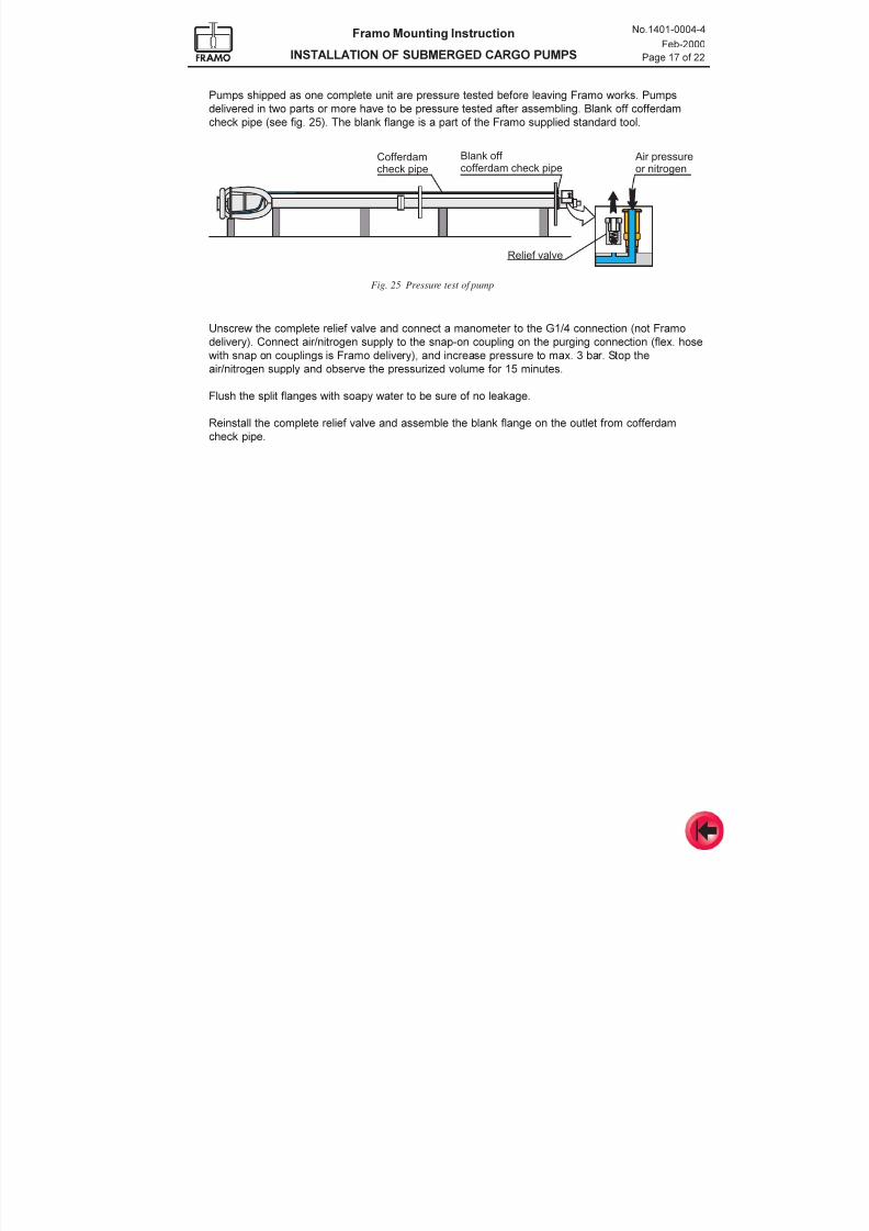
Unscrew the complete relief valve and connect a manometer to the G1/4 connection (not Framo
delivery). Connect air/nitrogen supply to the snap-on coupling on the purging connection (flex. hose
with snap on couplings is Framo delivery), and increase pressure to max. 3 bar. Stop the
air/nitrogen supply and observe the pressurized volume for 15 minutes.
Flush the split flanges with soapy water to be sure of no leakage.
Reinstall the complete relief valve and assemble the blank flange on the outlet from cofferdam
check pipe.
Air pressureor nitrogen
Relief valve
Blank off cofferdam check pipe
Cofferdamcheck pipe
Pumps shipped as one complete unit are pressure tested before leaving Framo works. Pumps
delivered in two parts or more have to be pressure tested after assembling. Blank off cofferdam
check pipe (see fig. 25). The blank flange is a part of the Framo supplied standard tool.
Fig. 25 Pressure test of pump
7/16/2019 Pompe Framo
http://slidepdf.com/reader/full/pompe-framo 40/175
Framo Mounting Instruction
INSTALLATION OF SUBMERGED CARGO PUMPS
No.1401-0004-4
Feb-2000
Page 18 of 22
6 INSTALLATION OF PUMPS IN TANK
The Framo cargo pumps have two different resilient arrangements on top plate. Installation of each
arrangement is described separately.
Preparations:
Welding, sandblasting and grinding must be finished and tank must be
properly cleaned before installation of pump in tank.
For carbon steel tanks, also coating must be finished before installation.
Pickling
Pickling will be required prior to installation if the pump has been exposed to iron dust during
storage or corroded surfaces/spots are detected. Framo recommend Avesta Pickling Paste or
equal types for stainless steel.Follow the manufacturers procedure for pickling before starting the work.
Blank flanges
Blank flanges and seals on top plate shall be left until connection of the pump to the vessels piping
systems. The blank flanges on the pumps suction opening and the protection around the pump
shaft shall be removed only by the Framo service engineer before water is filled into the tank.
Transport securing (Only on pumps with vacuum stripping pipe)
The steel wire on lower vacuum stripping pipe shall also be removed by the Framo service engineer.
Special tools required for installations are supplied by Framo in the toolbox.
See tool list for descriptions.
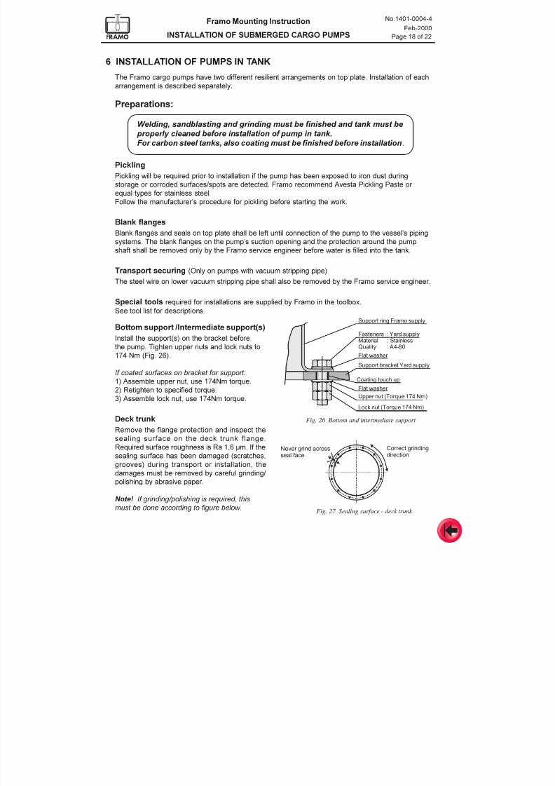
Fig. 27 Sealing surface - deck trunk
Bottom support /Intermediate support(s)
Install the support(s) on the bracket before
the pump. Tighten upper nuts and lock nuts to
174 Nm (Fig. 26).
If coated surfaces on bracket for support:
1) Assemble upper nut, use 174Nm torque.
2) Retighten to specified torque.3) Assemble lock nut, use 174Nm torque.
Deck trunk
Remove the flange protection and inspect the
sealing surface on the deck trunk flange.
Required surface roughness is Ra 1,6 µm. If the
sealing surface has been damaged (scratches,
grooves) during transport or installation, the
damages must be removed by careful grinding/
polishing by abrasive paper.
Note! If grinding/polishing is required, this
must be done according to figure below.
Fig. 26 Bottom and intermediate support
Correct grindingdirection
Never grind acrossseal face
Support ring Framo supply
FastenersMaterialQuality
: Yard supply: Stainless: A4-80
Support bracket Yard supply
Upper nut (Torque 174 Nm)Flat washer
Coating touch up
Flat washer
Lock nut (Torque 174 Nm)
7/16/2019 Pompe Framo
http://slidepdf.com/reader/full/pompe-framo 41/175
Framo Mounting Instruction
INSTALLATION OF SUBMERGED CARGO PUMPS
No.1401-0004-4
Feb-2000
Page 19 of 22
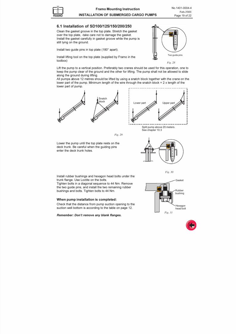
6.1 Installation of SD100/125/150/200/250
Clean the gasket groove in the top plate. Stretch the gasket
over the top plate, -take care not to damage the gasket.
Install the gasket carefully in gasket groove while the pump is
still lying on the ground.
Install two guide pins in top plate (180° apart).
Install lifting tool on the top plate (supplied by Framo in the
toolbox)
Lift the pump to a vertical position. Preferably two cranes should be used for this operation, one to
keep the pump clear of the ground and the other for lifting. The pump shall not be allowed to slide
along the ground during lifting.
All pumps above 12 metres should be lifted by using a snatch block together with the crane on the
lower part of the pump. Minimum length of the wire through the snatch block = 2 x length of thelower part of pump.
Two guide pins
Lower part Upper part
Split pump above 20 meters.See chapter 10.3
Snatchblock
Lower the pump until the top plate rests on the
deck trunk. Be careful when the guiding pins
enter the deck trunk holes.
Install rubber bushings and hexagon head bolts under the
trunk flange. Use Loctite on the bolts.
Tighten bolts in a diagonal sequence to 44 Nm. Remove
the two guide pins, and install the two remaining rubber
bushings and bolts. Tighten bolts to 44 Nm.
When pump installation is completed:
Check that the distance from pump suction opening to the
suction well bottom is according to the table on page 12.
Remember: Dont remove any blank flanges.
Fig. 28
Fig. 30
Fig. 31
Fig. 29
Rubber bushing
Hexagonhead bolt
Gasket
7/16/2019 Pompe Framo
http://slidepdf.com/reader/full/pompe-framo 42/175
Framo Mounting Instruction
INSTALLATION OF SUBMERGED CARGO PUMPS
No.1401-0004-4
Feb-2000
Page 20 of 22
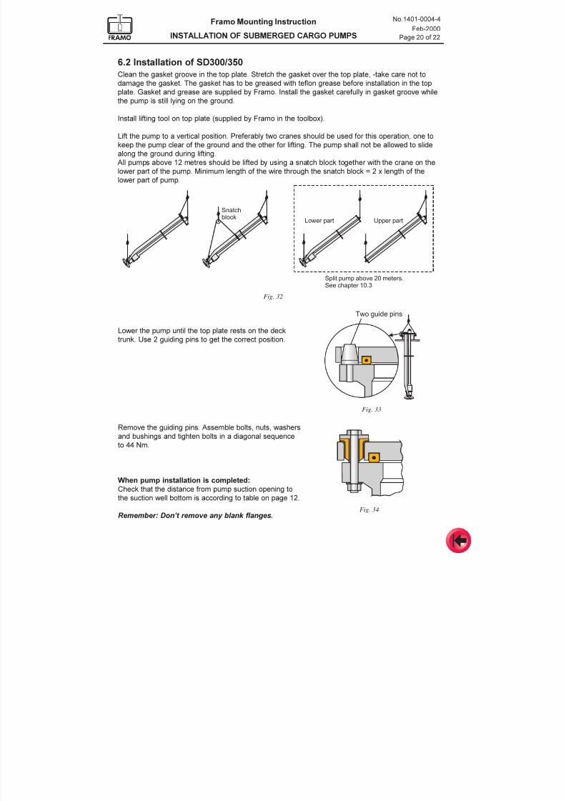
6.2 Installation of SD300/350
Clean the gasket groove in the top plate. Stretch the gasket over the top plate, -take care not to
damage the gasket. The gasket has to be greased with teflon grease before installation in the top
plate. Gasket and grease are supplied by Framo. Install the gasket carefully in gasket groove while
the pump is still lying on the ground.
Install lifting tool on top plate (supplied by Framo in the toolbox).
Lift the pump to a vertical position. Preferably two cranes should be used for this operation, one to
keep the pump clear of the ground and the other for lifting. The pump shall not be allowed to slide
along the ground during lifting.
All pumps above 12 metres should be lifted by using a snatch block together with the crane on the
lower part of the pump. Minimum length of the wire through the snatch block = 2 x length of the
lower part of pump.
Lower part Upper part
Split pump above 20 meters.See chapter 10.3
Snatchblock
Lower the pump until the top plate rests on the deck
trunk. Use 2 guiding pins to get the correct position.
Remove the guiding pins. Assemble bolts, nuts, washers
and bushings and tighten bolts in a diagonal sequence
to 44 Nm.
When pump installation is completed:
Check that the distance from pump suction opening to
the suction well bottom is according to table on page 12.
Remember: Dont remove any blank flanges.
Two guide pins
Fig. 33
Fig. 34
Fig. 32
7/16/2019 Pompe Framo
http://slidepdf.com/reader/full/pompe-framo 43/175
Framo Mounting Instruction
INSTALLATION OF SUBMERGED CARGO PUMPS
No.1401-0004-4
Feb-2000
Page 21 of 22
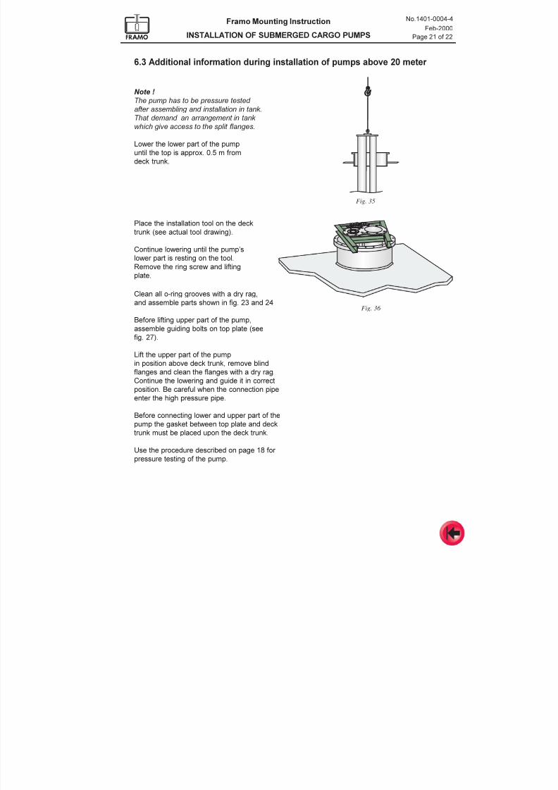
6.3 Additional information during installation of pumps above 20 meter
Lower the lower part of the pump
until the top is approx. 0.5 m from
deck trunk.
Place the installation tool on the deck
trunk (see actual tool drawing).
Continue lowering until the pumps
lower part is resting on the tool.
Remove the ring screw and lifting
plate.
Clean all o-ring grooves with a dry rag,and assemble parts shown in fig. 23 and 24
Before lifting upper part of the pump,
assemble guiding bolts on top plate (see
fig. 27).
Lift the upper part of the pump
in position above deck trunk, remove blind
flanges and clean the flanges with a dry rag.
Continue the lowering and guide it in correct
position. Be careful when the connection pipeenter the high pressure pipe.
Before connecting lower and upper part of the
pump the gasket between top plate and deck
trunk must be placed upon the deck trunk.
Use the procedure described on page 18 for
pressure testing of the pump.
Fig. 35
Fig. 36
Note !
The pump has to be pressure tested
after assembling and installation in tank.
That demand an arrangement in tank
which give access to the split flanges.
7/16/2019 Pompe Framo
http://slidepdf.com/reader/full/pompe-framo 44/175
Framo Mounting Instruction
INSTALLATION OF SUBMERGED CARGO PUMPS
No.1401-0004-4
Feb-2000
Page 22 of 22
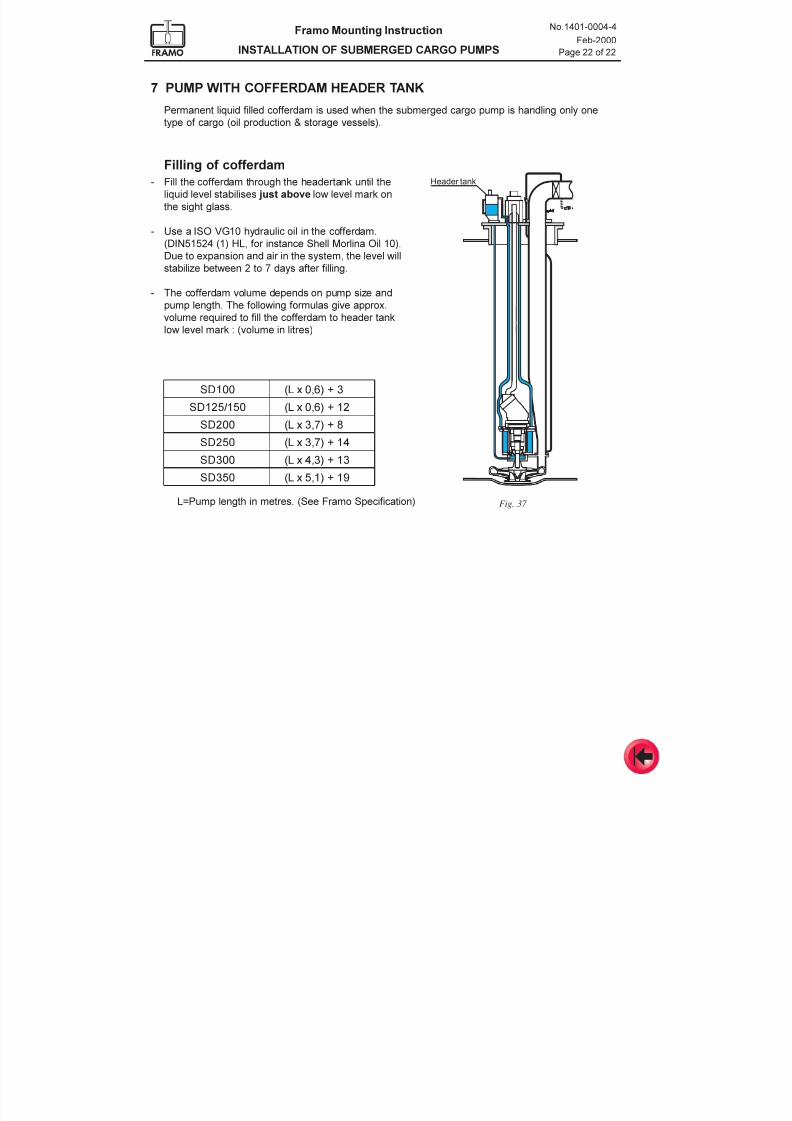
7 PUMP WITH COFFERDAM HEADER TANK
Permanent liquid filled cofferdam is used when the submerged cargo pump is handling only one
type of cargo (oil production & storage vessels).
Filling of cofferdam
- Fill the cofferdam through the headertank until the
liquid level stabilises just above low level mark on
the sight glass.
- Use a ISO VG10 hydraulic oil in the cofferdam.
(DIN51524 (1) HL, for instance Shell Morlina Oil 10).
Due to expansion and air in the system, the level will
stabilize between 2 to 7 days after filling.
- The cofferdam volume depends on pump size and
pump length. The following formulas give approx.
volume required to fill the cofferdam to header tank
low level mark : (volume in litres)
001DS 3+)6,0xL(
051/521DS 21+)6,0xL(
002DS 8+)7,3xL(
052DS 41+)7,3xL(
003DS 31+)3,4xL(
053DS 91+)1,5xL(
L=Pump length in metres. (See Framo Specification)
Header tank
Fig. 37
7/16/2019 Pompe Framo
http://slidepdf.com/reader/full/pompe-framo 45/175
Framo
Mounting Instruction
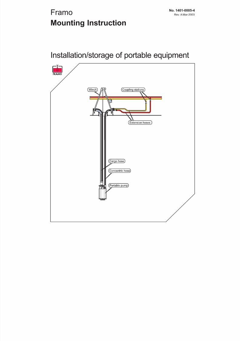
Installation/storage of portable equipment
No. 1401-0005-4
Rev. A Mar-2003
7/16/2019 Pompe Framo
http://slidepdf.com/reader/full/pompe-framo 46/175
Framo Mounting Instruction
INSTALLATION OF PORTABLE EQUIPMENT
No.1401-0005-4
Rev. A Mar-2003
Page 2 of 3
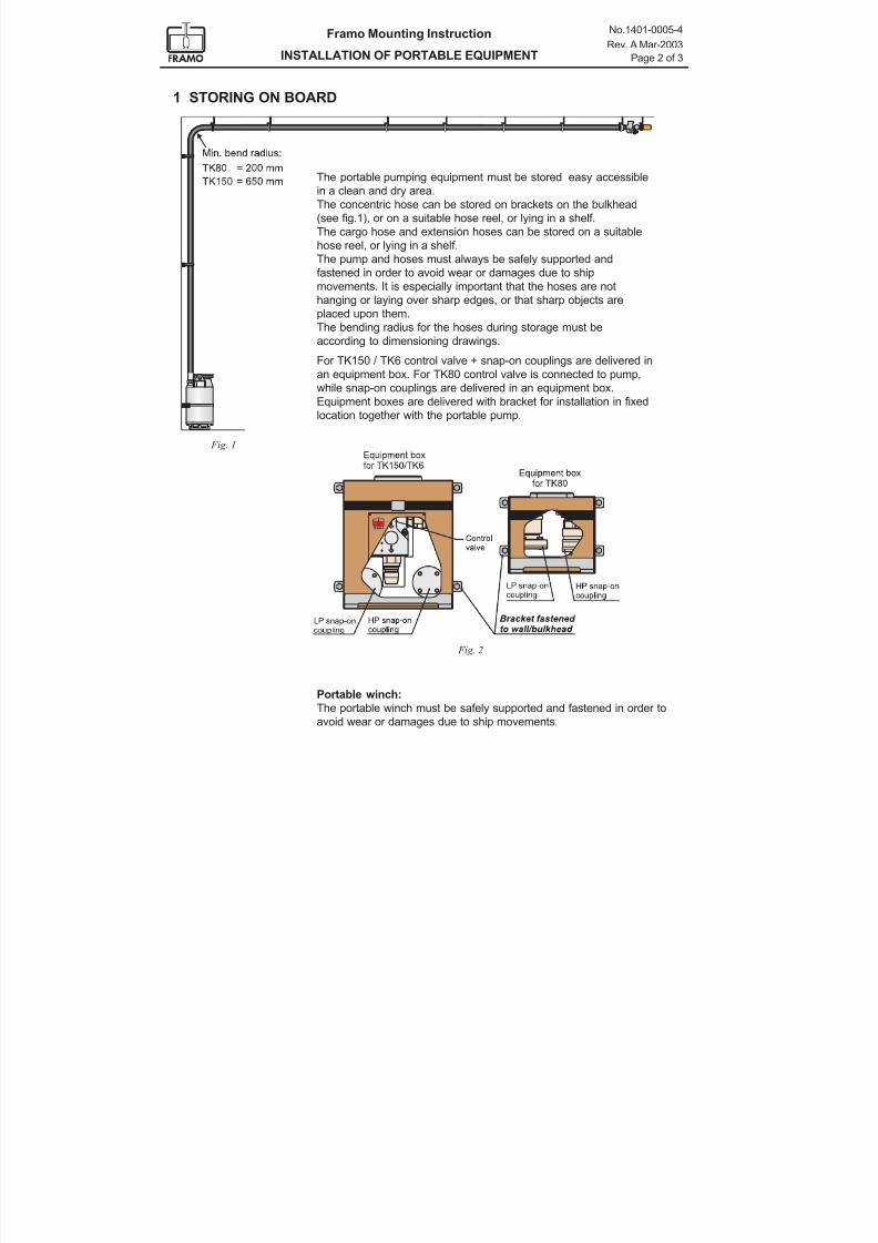
1 STORING ON BOARD
The portable pumping equipment must be stored easy accessible
in a clean and dry area.
The concentric hose can be stored on brackets on the bulkhead
(see fig.1), or on a suitable hose reel, or lying in a shelf.
The cargo hose and extension hoses can be stored on a suitable
hose reel, or lying in a shelf.
The pump and hoses must always be safely supported and
fastened in order to avoid wear or damages due to ship
movements. It is especially important that the hoses are not
hanging or laying over sharp edges, or that sharp objects are
placed upon them.
The bending radius for the hoses during storage must be
according to dimensioning drawings.
For TK150 / TK6 control valve + snap-on couplings are delivered in
an equipment box. For TK80 control valve is connected to pump,
while snap-on couplings are delivered in an equipment box.
Equipment boxes are delivered with bracket for installation in fixed
location together with the portable pump.
Fig. 1
Portable winch:
The portable winch must be safely supported and fastened in order to
avoid wear or damages due to ship movements.
Fig. 2
7/16/2019 Pompe Framo
http://slidepdf.com/reader/full/pompe-framo 47/175
Framo Mounting Instruction
INSTALLATION OF PORTABLE EQUIPMENT
No.1401-0005-4
Rev. A Mar-2003
Page 3 of 3
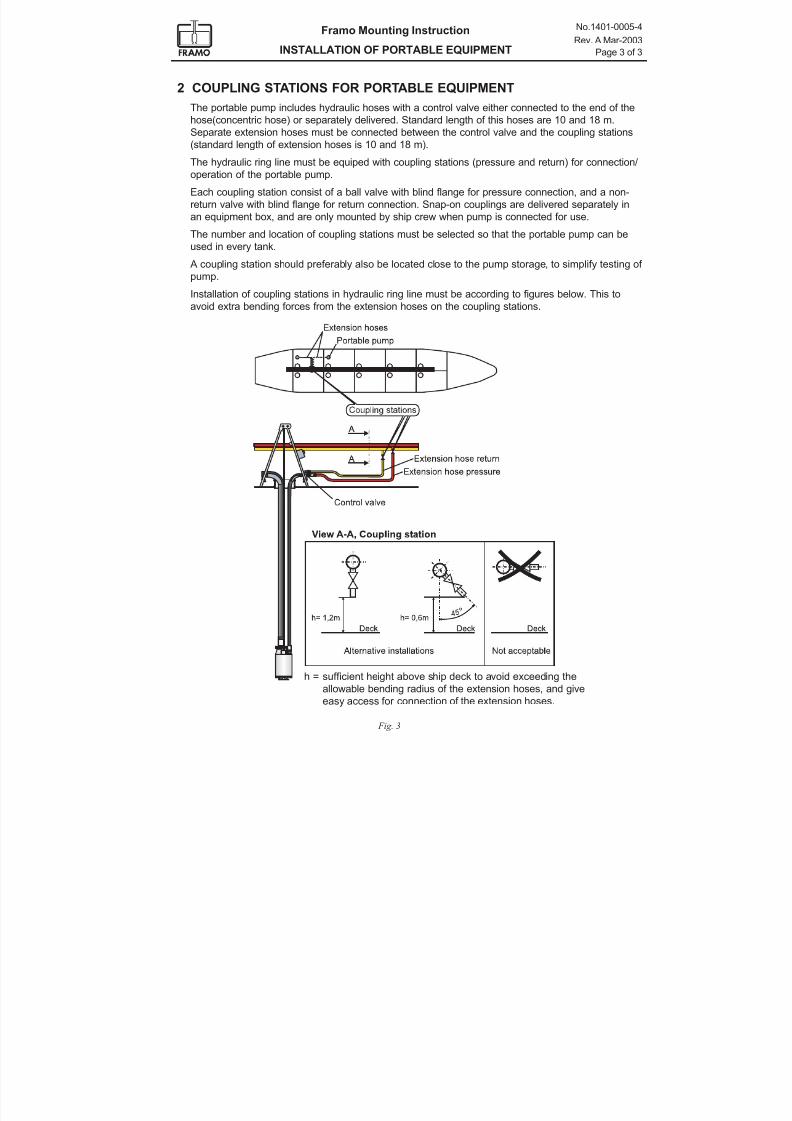
h = sufficient height above ship deck to avoid exceeding the
allowable bending radius of the extension hoses, and giveeasy access for connection of the extension hoses.
2 COUPLING STATIONS FOR PORTABLE EQUIPMENT
The portable pump includes hydraulic hoses with a control valve either connected to the end of the
hose(concentric hose) or separately delivered. Standard length of this hoses are 10 and 18 m.
Separate extension hoses must be connected between the control valve and the coupling stations
(standard length of extension hoses is 10 and 18 m).
The hydraulic ring line must be equiped with coupling stations (pressure and return) for connection/
operation of the portable pump.
Each coupling station consist of a ball valve with blind flange for pressure connection, and a non-
return valve with blind flange for return connection. Snap-on couplings are delivered separately in
an equipment box, and are only mounted by ship crew when pump is connected for use.
The number and location of coupling stations must be selected so that the portable pump can be
used in every tank.
A coupling station should preferably also be located close to the pump storage, to simplify testing of
pump.
Installation of coupling stations in hydraulic ring line must be according to figures below. This to
avoid extra bending forces from the extension hoses on the coupling stations.
Fig. 3
7/16/2019 Pompe Framo
http://slidepdf.com/reader/full/pompe-framo 48/175
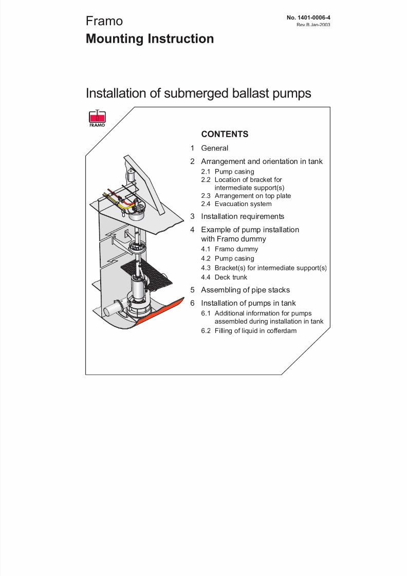
Framo
Mounting Instruction
Installation of submerged ballast pumps
No. 1401-0006-4
Rev.B Jan-2003
CONTENTS
1 General
2 Arrangement and orientation in tank
2.1 Pump casing
2.2 Location of bracket for intermediate support(s)
2.3 Arrangement on top plate
2.4 Evacuation system
3 Installation requirements
4 Example of pump installation
with Framo dummy
4.1 Framo dummy
4.2 Pump casing
4.3 Bracket(s) for intermediate support(s)
4.4 Deck trunk
5 Assembling of pipe stacks
6 Installation of pumps in tank
6.1 Additional information for pumpsassembled during installation in tank
6.2 Filling of liquid in cofferdam
7/16/2019 Pompe Framo
http://slidepdf.com/reader/full/pompe-framo 49/175
Framo Mounting Instruction
INSTALLATION OF SUBMERGED BALLAST PUMPS
No.1401-0006-4
Rev.B Jan-2003
Page 2 of 23
Figures in this procedure are made general for all types of submerged ballast pumps. It is assumed
that a “dummy equipment package” intended for the pump type to be installed, is available. For
further information, see drawings for the actual ballast pump, deck trunk, intermediate support anddummy.
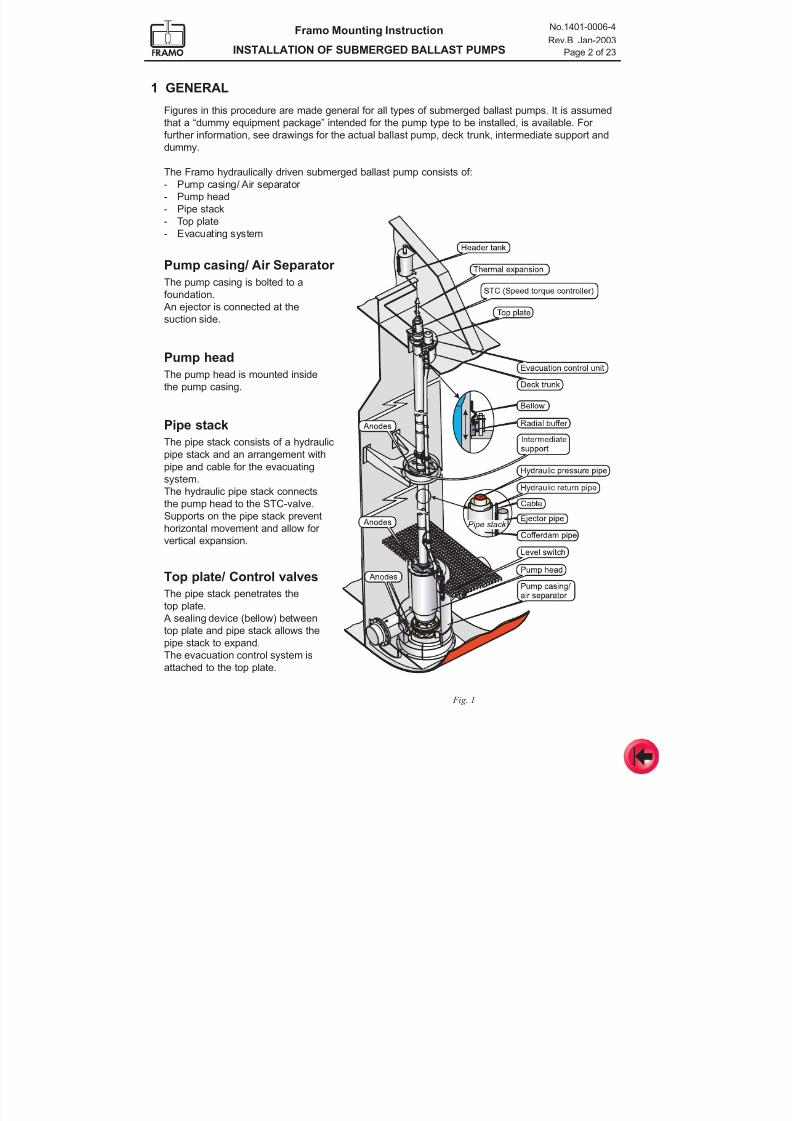
The Framo hydraulically driven submerged ballast pump consists of:
- Pump casing/ Air separator
- Pump head
- Pipe stack
- Top plate
- Evacuating system
1 GENERAL
Fig. 1
Pump casing/ Air Separator
The pump casing is bolted to a
foundation.
An ejector is connected at the
suction side.
Pump head
The pump head is mounted inside
the pump casing.
Pipe stack
The pipe stack consists of a hydraulic
pipe stack and an arrangement with
pipe and cable for the evacuating
system.
The hydraulic pipe stack connects
the pump head to the STC-valve.
Supports on the pipe stack prevent
horizontal movement and allow for
vertical expansion.
Top plate/ Control valves
The pipe stack penetrates the
top plate.
A sealing device (bellow) between
top plate and pipe stack allows the
pipe stack to expand.
The evacuation control system is
attached to the top plate.
7/16/2019 Pompe Framo
http://slidepdf.com/reader/full/pompe-framo 50/175
Framo Mounting Instruction
INSTALLATION OF SUBMERGED BALLAST PUMPS
No.1401-0006-4
Rev.B Jan-2003
Page 3 of 23
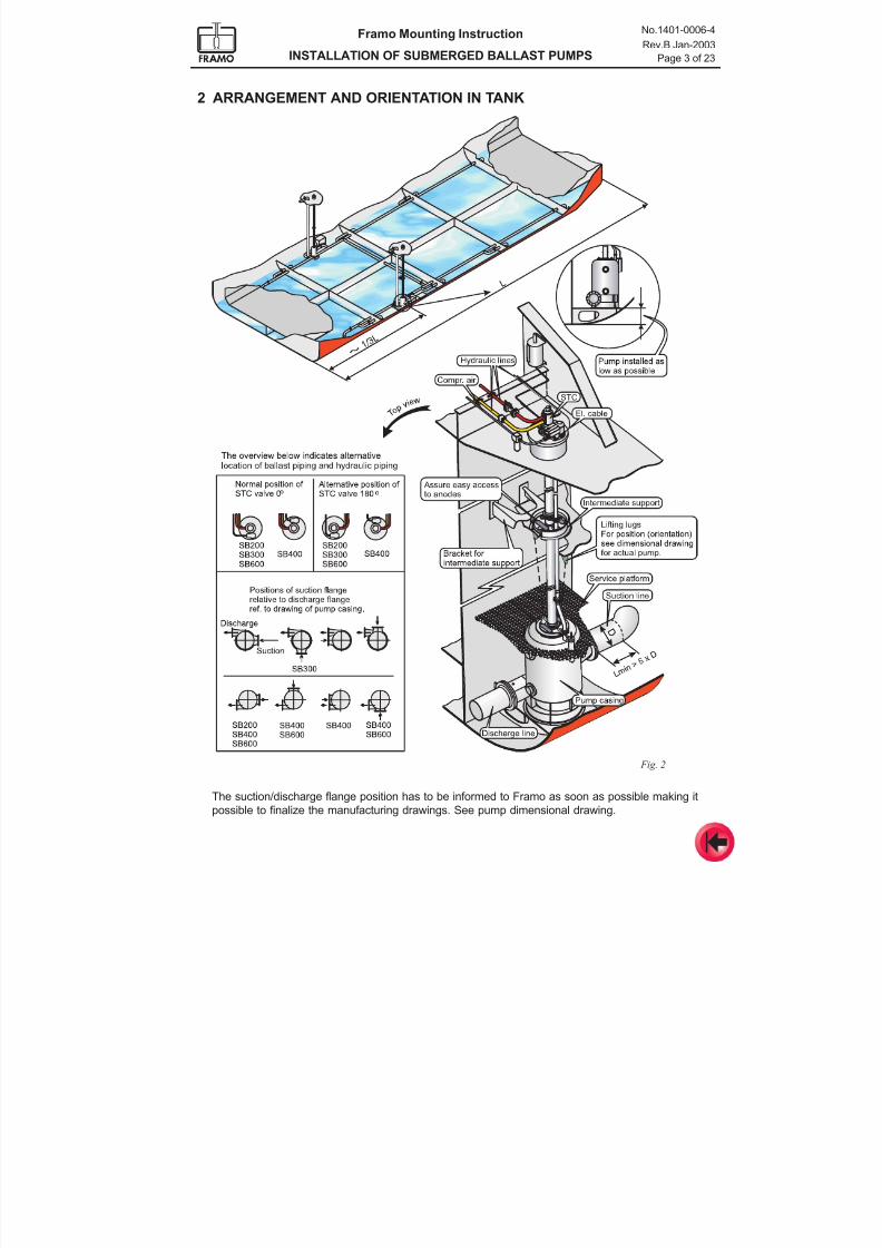
2 ARRANGEMENT AND ORIENTATION IN TANK
Fig. 2
The suction/discharge flange position has to be informed to Framo as soon as possible making it
possible to finalize the manufacturing drawings. See pump dimensional drawing.
7/16/2019 Pompe Framo
http://slidepdf.com/reader/full/pompe-framo 51/175
Framo Mounting Instruction
INSTALLATION OF SUBMERGED BALLAST PUMPS
No.1401-0006-4
Rev.B Jan-2003
Page 4 of 23
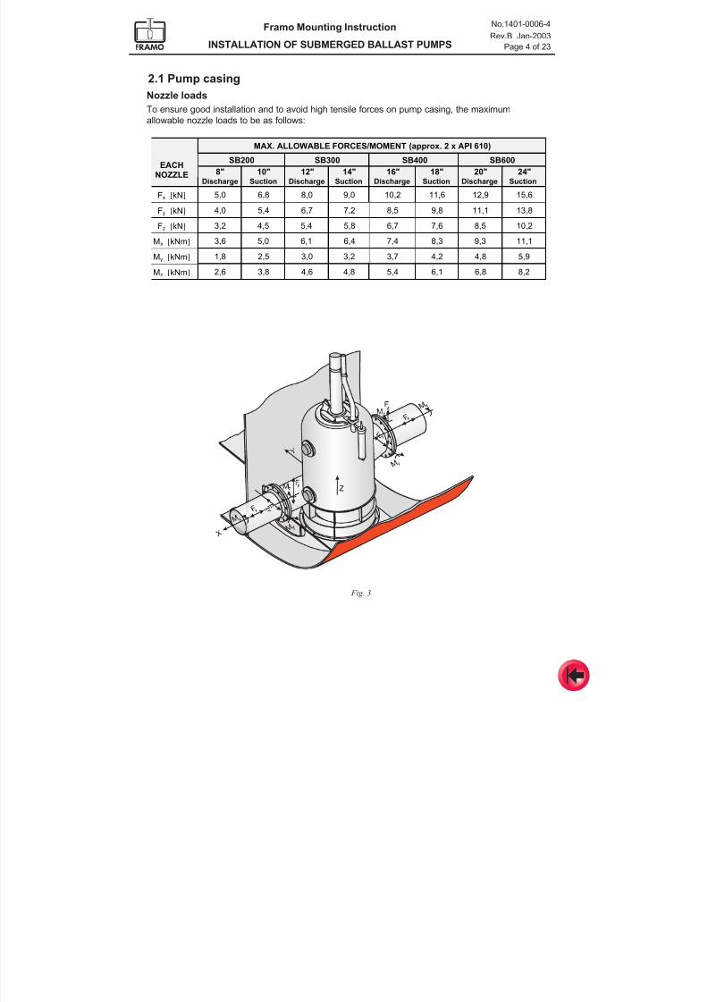
2.1 Pump casing
Nozzle loads
To ensure good installation and to avoid high tensile forces on pump casing, the maximum
allowable nozzle loads to be as follows:
Fig. 3
MAX. ALLOWABLE FORCES/MOMENT (approx. 2 x API 610)
SB200 SB300 SB400 SB600
8" 10" 12" 14" 16" 18" 20" 24"EACH
NOZZLEDischarge Suction Discharge Suction Discharge Suction Discharge Suction
Fx [kN] 5,0 6,8 8,0 9,0 10,2 11,6 12,9 15,6
Fy [kN] 4,0 5,4 6,7 7,2 8,5 9,8 11,1 13,8
Fz [kN] 3,2 4,5 5,4 5,8 6,7 7,6 8,5 10,2
Mx [kNm] 3,6 5,0 6,1 6,4 7,4 8,3 9,3 11,1
My [kNm] 1,8 2,5 3,0 3,2 3,7 4,2 4,8 5,9
Mz [kNm] 2,6 3,8 4,6 4,8 5,4 6,1 6,8 8,2
7/16/2019 Pompe Framo
http://slidepdf.com/reader/full/pompe-framo 52/175
Framo Mounting Instruction
INSTALLATION OF SUBMERGED BALLAST PUMPS
No.1401-0006-4
Rev.B Jan-2003
Page 5 of 23
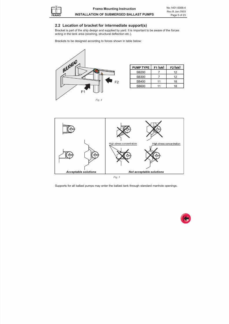
2.2 Location of bracket for intermediate support(s)
Bracket is part of the ship design and supplied by yard. It is important to be aware of the forces
acting in the tank area (sloshing, structural deflection etc.).
Brackets to be designed according to forces shown in table below:
Supports for all ballast pumps may enter the ballast tank through standard manhole openings.
Fig. 4
Fig. 5
PUMP TYPE F1 [[[[kN]]]] F2 [[[[kN]]]]
SB200 7 12
SB300 7 12
SB400 11 18
SB600 11 18
7/16/2019 Pompe Framo
http://slidepdf.com/reader/full/pompe-framo 53/175
Framo Mounting Instruction
INSTALLATION OF SUBMERGED BALLAST PUMPS
No.1401-0006-4
Rev.B Jan-2003
Page 6 of 23
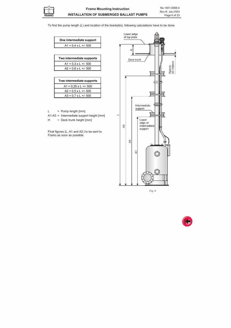
To find the pump length (L) and location of the bracket(s), following calculations have to be done:
L = Pump length [mm]
A1-A3 = Intermediate support height [mm]
H = Deck trunk height [mm]
Final figures (L, A1 and A2 ) to be sent to
Framo as soon as possible.
One intermediate support
A1 = 0,4 x L +/- 500
Two intermediate supports
A1 = 0,3 x L +/- 500
A2 = 0,6 x L +/- 500
Tree intermediate supports
A1 = 0,25 x L +/- 500
A2 = 0,5 x L +/- 500
A3 = 0,7 x L +/- 500
Fig. 6
7/16/2019 Pompe Framo
http://slidepdf.com/reader/full/pompe-framo 54/175
Framo Mounting Instruction
INSTALLATION OF SUBMERGED BALLAST PUMPS
No.1401-0006-4
Rev.B Jan-2003
Page 7 of 23
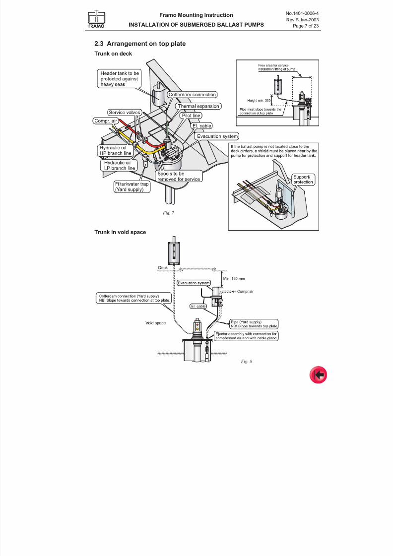
2.3 Arrangement on top plate
Trunk on deck
Fig. 7
Fig. 8
Trunk in void space
7/16/2019 Pompe Framo
http://slidepdf.com/reader/full/pompe-framo 55/175
Framo Mounting Instruction
INSTALLATION OF SUBMERGED BALLAST PUMPS
No.1401-0006-4
Rev.B Jan-2003
Page 8 of 23
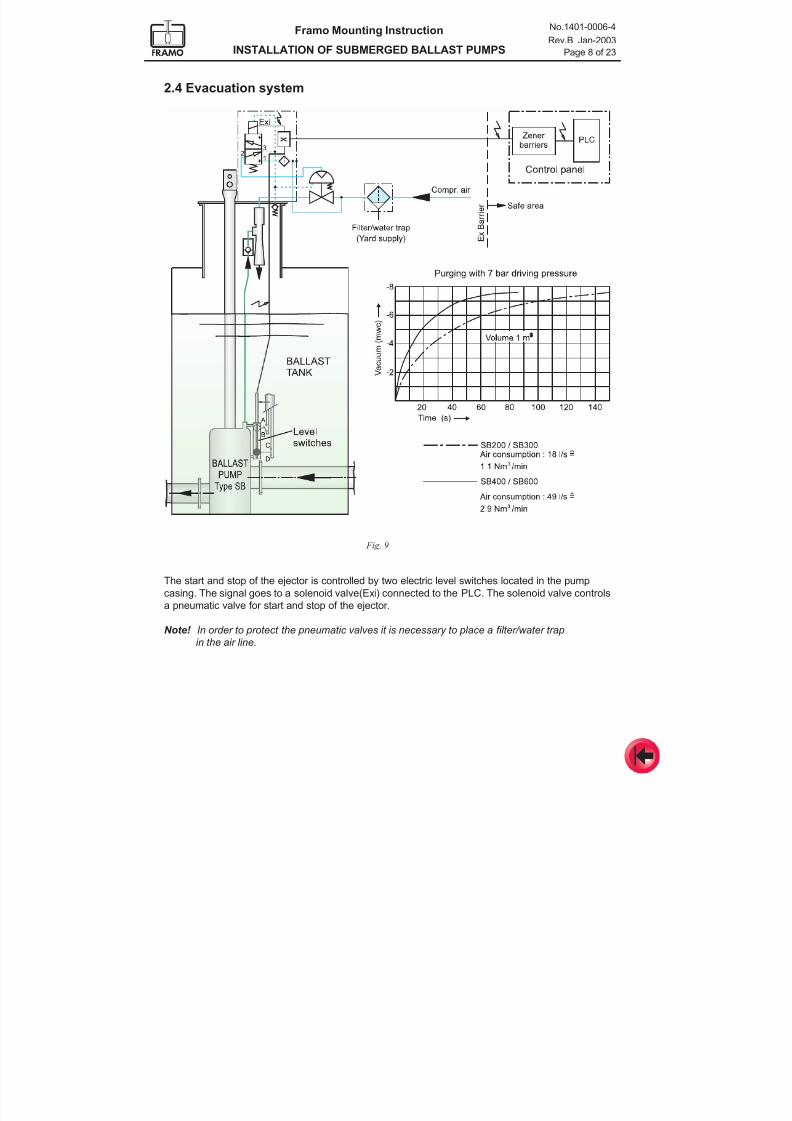
2.4 Evacuation system
The start and stop of the ejector is controlled by two electric level switches located in the pump
casing. The signal goes to a solenoid valve(Exi) connected to the PLC. The solenoid valve controls
a pneumatic valve for start and stop of the ejector.
Note! In order to protect the pneumatic valves it is necessary to place a filter/water trap
in the air line.
Fig. 9
7/16/2019 Pompe Framo
http://slidepdf.com/reader/full/pompe-framo 56/175
Framo Mounting Instruction
INSTALLATION OF SUBMERGED BALLAST PUMPS
No.1401-0006-4
Rev.B Jan-2003
Page 9 of 23
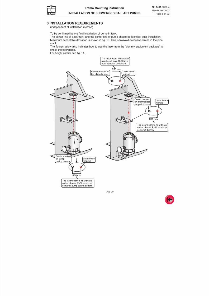
3 INSTALLATION REQUIREMENTS(independent of installation method)
To be confirmed before final installation of pump in tank.
The center line of deck trunk and the center line of pump should be identical after installation.Maximum acceptable deviation is shown in fig. 10. This is to avoid excessive stress in the pipe
stack.
The figures below also indicates how to use the laser from the “dummy equipment package” to
check the tolerances.
For height control see fig. 11.
Fig. 10
7/16/2019 Pompe Framo
http://slidepdf.com/reader/full/pompe-framo 57/175
Framo Mounting Instruction
INSTALLATION OF SUBMERGED BALLAST PUMPS
No.1401-0006-4
Rev.B Jan-2003
Page 10 of 23
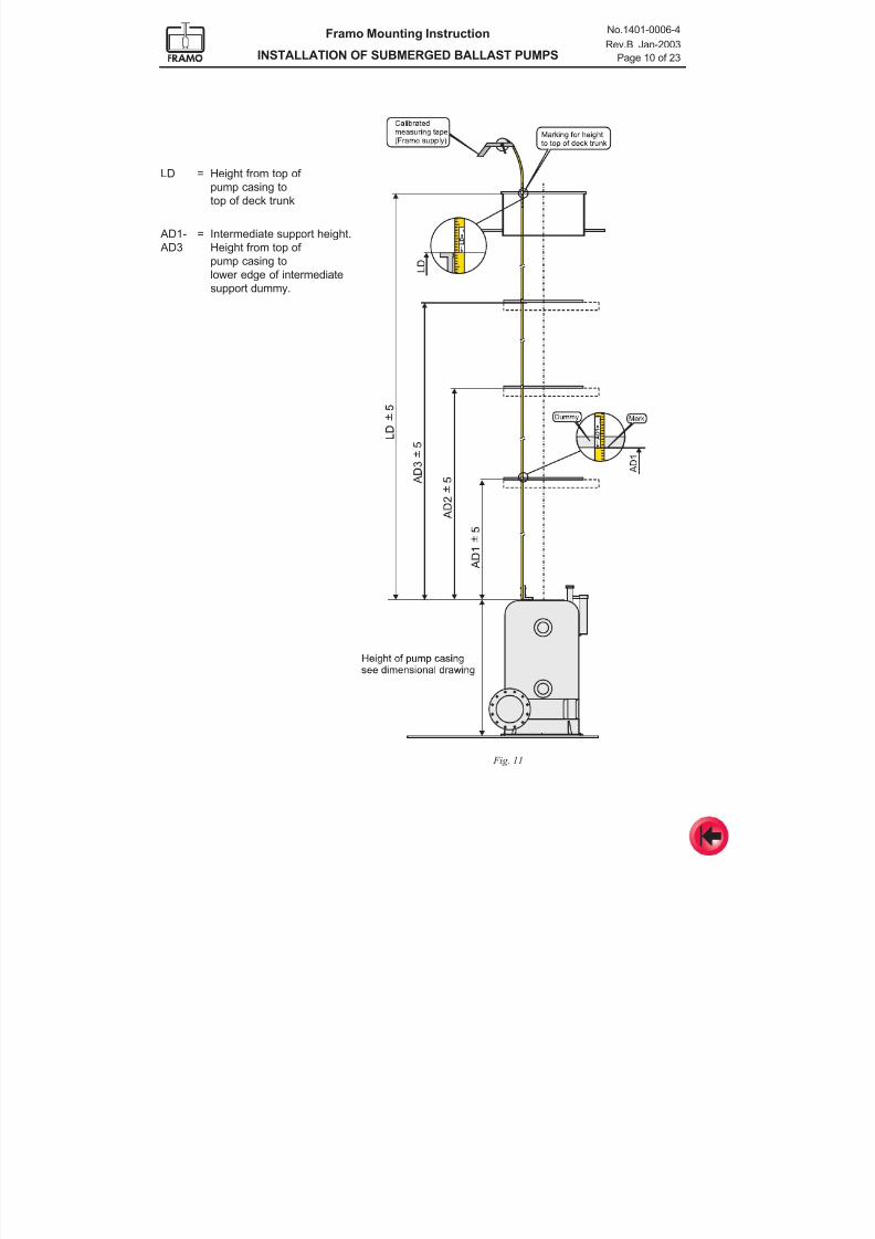
Fig. 11
LD = Height from top of
pump casing to
top of deck trunk
AD1- = Intermediate support height.
AD3 Height from top of
pump casing to
lower edge of intermediate
support dummy.
7/16/2019 Pompe Framo
http://slidepdf.com/reader/full/pompe-framo 58/175
Framo Mounting Instruction
INSTALLATION OF SUBMERGED BALLAST PUMPS
No.1401-0006-4
Rev.B Jan-2003
Page 11 of 23
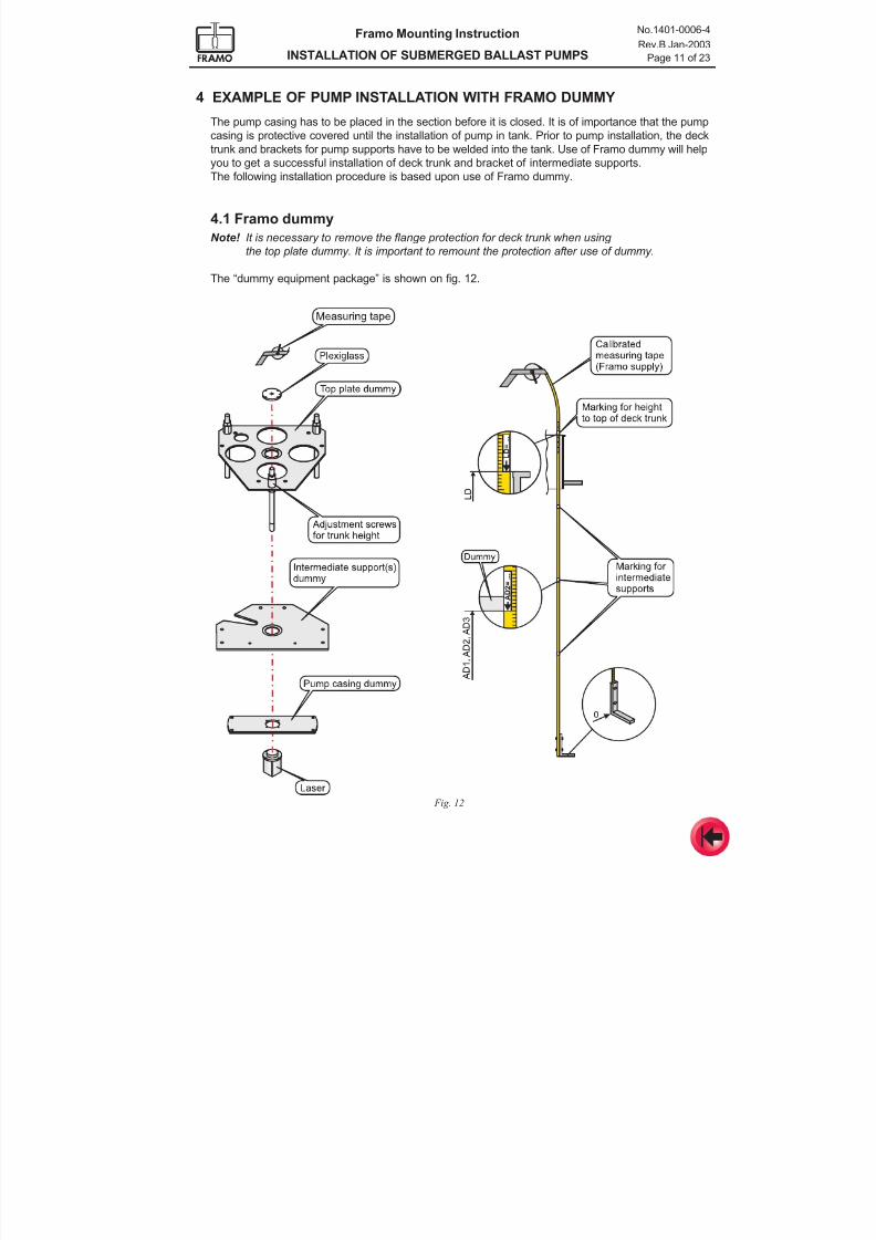
4 EXAMPLE OF PUMP INSTALLATION WITH FRAMO DUMMY
The pump casing has to be placed in the section before it is closed. It is of importance that the pump
casing is protective covered until the installation of pump in tank. Prior to pump installation, the deck
trunk and brackets for pump supports have to be welded into the tank. Use of Framo dummy will helpyou to get a successful installation of deck trunk and bracket of intermediate supports.
The following installation procedure is based upon use of Framo dummy.
4.1 Framo dummy
Note! It is necessary to remove the flange protection for deck trunk when using
the top plate dummy. It is important to remount the protection after use of dummy.
The “dummy equipment package” is shown on fig. 12.
Fig. 12
7/16/2019 Pompe Framo
http://slidepdf.com/reader/full/pompe-framo 59/175
Framo Mounting Instruction
INSTALLATION OF SUBMERGED BALLAST PUMPS
No.1401-0006-4
Rev.B Jan-2003
Page 12 of 23
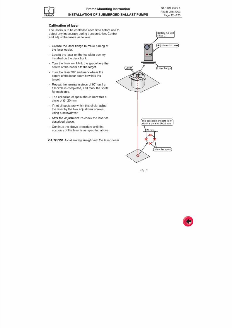
Calibration of laser
The lasers is to be controlled each time before use to
detect any inaccuracy during transportation. Control
and adjust the lasers as follows:
Fig. 13
- Grease the laser flange to make turning of
the laser easier.
- Locate the laser on the top plate dummy
installed on the deck trunk.
- Turn the laser on. Mark the spot where the
centre of the beam hits the target.
- Turn the laser 90° and mark where the
centre of the laser beam now hits the
target.
- Repeat the turning in steps of 90° until a
full circle is completed, and mark the spots
for each step.
- The collection of spots should be within a
circle of Ø=20 mm.
- If not all spots are within this circle, adjust
the laser by the two adjustment screws,
using a screwdriver.
- After the adjustment, re-check the laser as
described above.
- Continue the above procedure until the
accuracy of the laser is as specified above.
CAUTION! Avoid staring straight into the laser beam.
7/16/2019 Pompe Framo
http://slidepdf.com/reader/full/pompe-framo 60/175
Framo Mounting Instruction
INSTALLATION OF SUBMERGED BALLAST PUMPS
No.1401-0006-4
Rev.B Jan-2003
Page 13 of 23
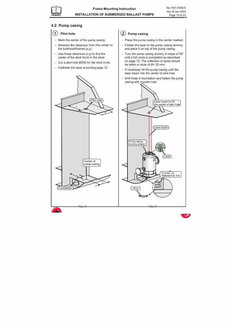
4.2 Pump casing
Fig. 14
1
- Mark the center of the pump casing.
- Measure the distances from this center to
the bulkhead/frames (x,y).
- Use these distances (x,y) to find the
center of the deck trunk in the deck.
- Cut a pilot hole Ø250 for the deck trunk.
- Calibrate the laser according page 12.
Pilot hole 2
Fig. 15
- Place the pump casing in the center marked.
- Fasten the laser to the pump casing dummy
and place it on top of the pump casing.
- Turn the pump casing dummy in steps of 90°
until a full circle is completed as described
on page 12. The collection of spots should
be within a circle of Ø= 20 mm.
- If necessary tilt the pump casing until the
laser beam hits the center of pilot hole.
- Drill holes in foundation and fasten the pump
casing with counter nuts.
Pump casing
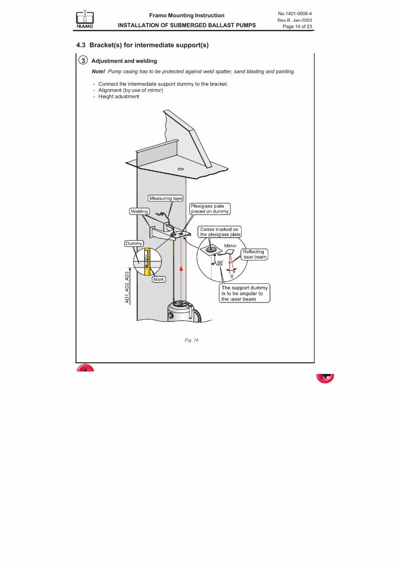
7/16/2019 Pompe Framo
http://slidepdf.com/reader/full/pompe-framo 61/175
Framo Mounting Instruction
INSTALLATION OF SUBMERGED BALLAST PUMPS
No.1401-0006-4
Rev.B Jan-2003
Page 14 of 23
4.3 Bracket(s) for intermediate support(s)
Fig. 16
Note! Pump casing has to be protected against weld spatter, sand blasting and painting.
- Connect the intermediate support dummy to the bracket.
- Alignment (by use of mirror)
- Height adustment
3 Adjustment and welding
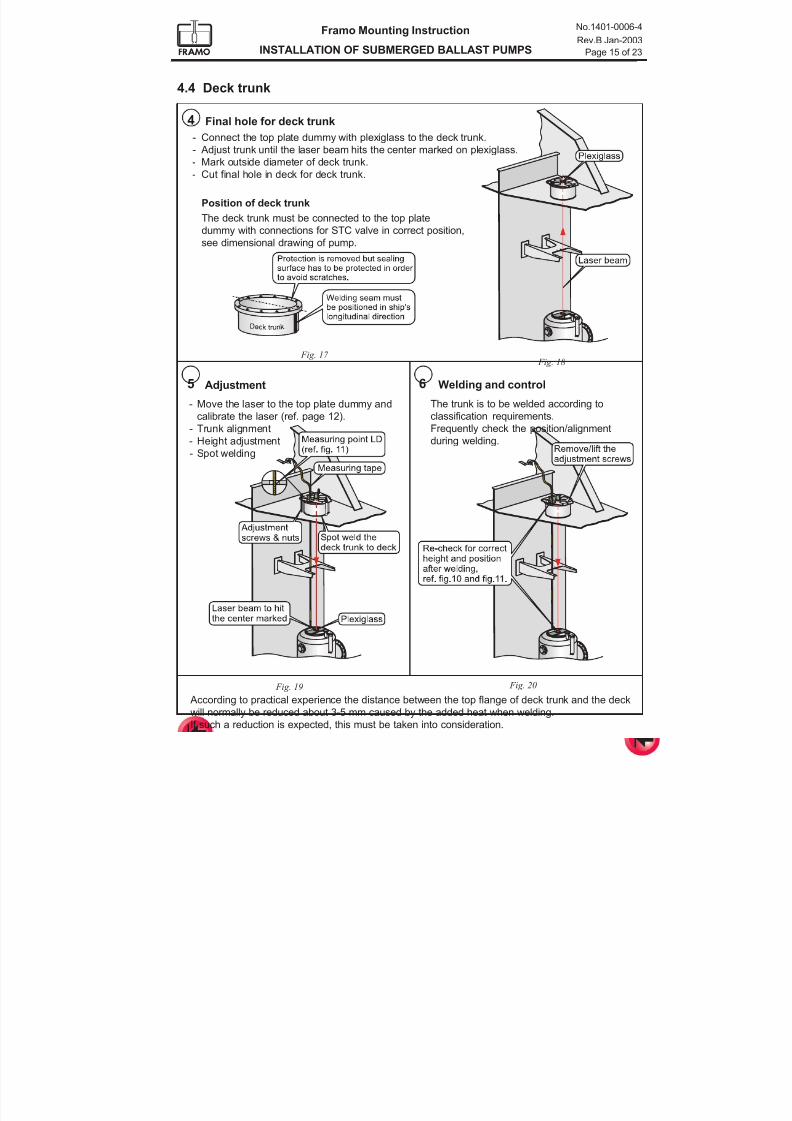
7/16/2019 Pompe Framo
http://slidepdf.com/reader/full/pompe-framo 62/175
Framo Mounting Instruction
INSTALLATION OF SUBMERGED BALLAST PUMPS
No.1401-0006-4
Rev.B Jan-2003
Page 15 of 23
- Move the laser to the top plate dummy and
calibrate the laser (ref. page 12).- Trunk alignment
- Height adjustment
- Spot welding
5 6 Welding and control
The trunk is to be welded according to
classification requirements.Frequently check the position/alignment
during welding.
Adjustment
Fig. 19 Fig. 20
Fig. 18
Position of deck trunk
The deck trunk must be connected to the top plate
dummy with connections for STC valve in correct position,
see dimensional drawing of pump.
- Connect the top plate dummy with plexiglass to the deck trunk.- Adjust trunk until the laser beam hits the center marked on plexiglass.
- Mark outside diameter of deck trunk.
- Cut final hole in deck for deck trunk.
4 Final hole for deck trunk
4.4 Deck trunk
Fig. 17
According to practical experience the distance between the top flange of deck trunk and the deck
will normally be reduced about 3-5 mm caused by the added heat when welding.
If such a reduction is expected, this must be taken into consideration.
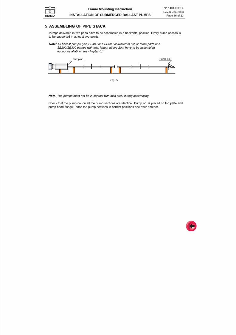
7/16/2019 Pompe Framo
http://slidepdf.com/reader/full/pompe-framo 63/175
Framo Mounting Instruction
INSTALLATION OF SUBMERGED BALLAST PUMPS
No.1401-0006-4
Rev.B Jan-2003
Page 16 of 23
5 ASSEMBLING OF PIPE STACK
Pumps delivered in two parts have to be assembled in a horizontal position. Every pump section is
to be supported in at least two points.
Note! All ballast pumps type SB400 and SB600 delivered in two or three parts and
SB200/SB300 pumps with total length above 20m have to be assembled
during installation, see chapter 6.1.
Fig. 21
Note! The pumps must not be in contact with mild steel during assembling.
Check that the pump no. on all the pump sections are identical. Pump no. is placed on top plate and
pump head flange. Place the pump sections in correct positions one after another.
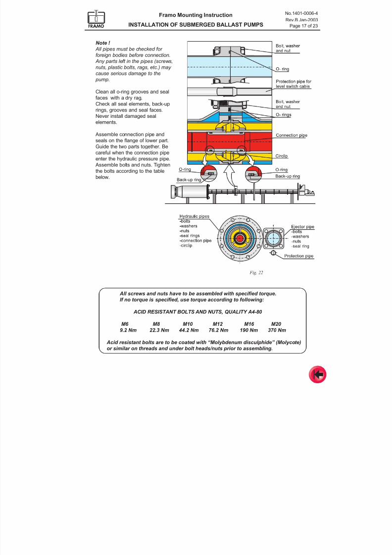
7/16/2019 Pompe Framo
http://slidepdf.com/reader/full/pompe-framo 64/175
Framo Mounting Instruction
INSTALLATION OF SUBMERGED BALLAST PUMPS
No.1401-0006-4
Rev.B Jan-2003
Page 17 of 23
Note !
All pipes must be checked for
foreign bodies before connection.
Any parts left in the pipes (screws,
nuts, plastic bolts, rags, etc.) may cause serious damage to the
pump.
Clean all o-ring grooves and seal
faces with a dry rag.
Check all seal elements, back-up
rings, grooves and seal faces.
Never install damaged seal
elements.
Assemble connection pipe and
seals on the flange of lower part.
Guide the two parts together. Be
careful when the connection pipe
enter the hydraulic pressure pipe.
Assemble bolts and nuts. Tighten
the bolts according to the table
below.
All screws and nuts have to be assembled with specified torque.
If no torque is specified, use torque according to following:
ACID RESISTANT BOLTS AND NUTS, QUALITY A4-80
M6 M8 M10 M12 M16 M20
9.2 Nm 22.3 Nm 44.2 Nm 76.2 Nm 190 Nm 370 Nm
Acid resistant bolts are to be coated with “Molybdenum disculphide” (Molycote)or similar on threads and under bolt heads/nuts prior to assembling.
Fig. 22
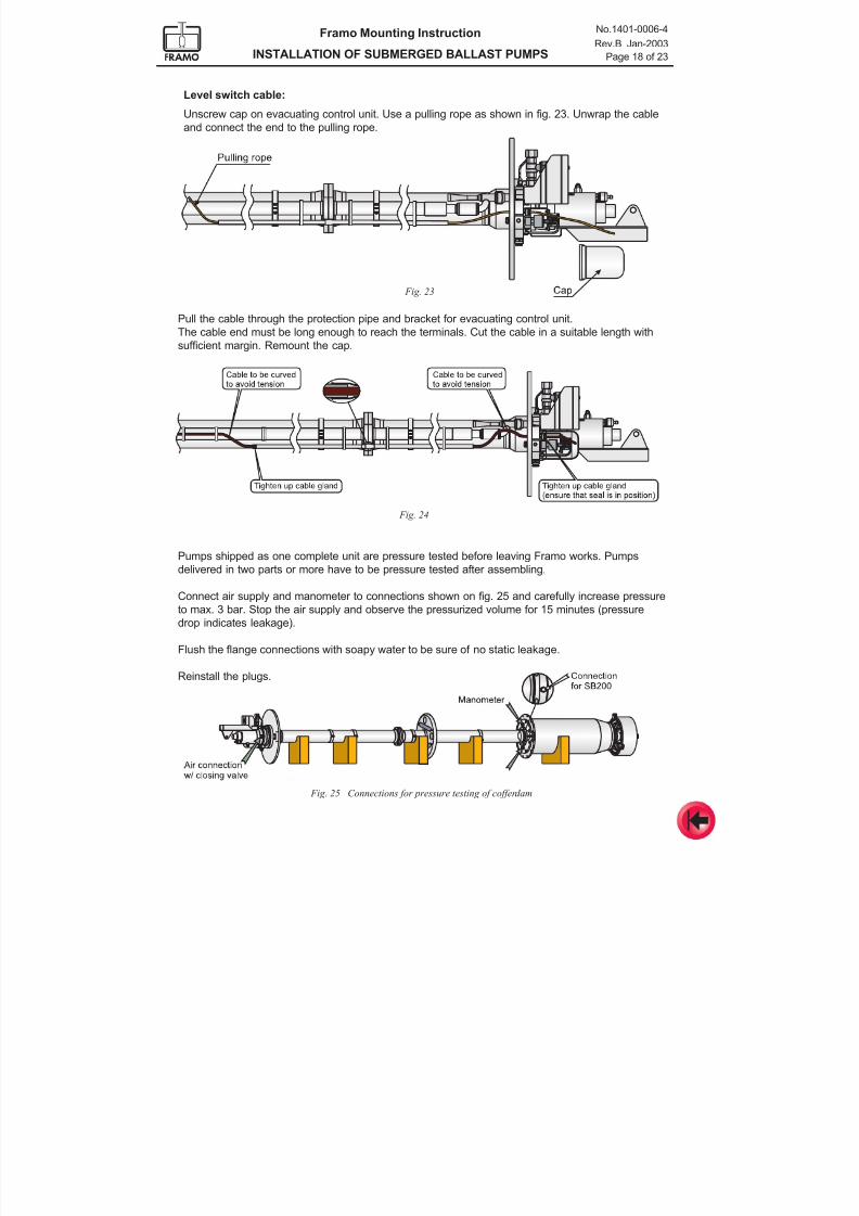
7/16/2019 Pompe Framo
http://slidepdf.com/reader/full/pompe-framo 65/175
Framo Mounting Instruction
INSTALLATION OF SUBMERGED BALLAST PUMPS
No.1401-0006-4
Rev.B Jan-2003
Page 18 of 23
Level switch cable:
Unscrew cap on evacuating control unit. Use a pulling rope as shown in fig. 23. Unwrap the cable
and connect the end to the pulling rope.
Fig. 24
Pumps shipped as one complete unit are pressure tested before leaving Framo works. Pumps
delivered in two parts or more have to be pressure tested after assembling.
Connect air supply and manometer to connections shown on fig. 25 and carefully increase pressureto max. 3 bar. Stop the air supply and observe the pressurized volume for 15 minutes (pressure
drop indicates leakage).
Flush the flange connections with soapy water to be sure of no static leakage.
Reinstall the plugs.
Fig. 25 Connections for pressure testing of cofferdam
Pull the cable through the protection pipe and bracket for evacuating control unit.
The cable end must be long enough to reach the terminals. Cut the cable in a suitable length with
sufficient margin. Remount the cap.
Fig. 23
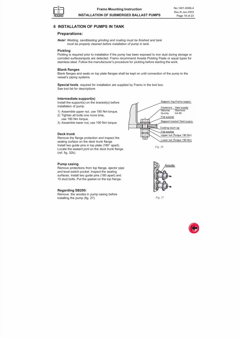
7/16/2019 Pompe Framo
http://slidepdf.com/reader/full/pompe-framo 66/175
Framo Mounting Instruction
INSTALLATION OF SUBMERGED BALLAST PUMPS
No.1401-0006-4
Rev.B Jan-2003
Page 19 of 23
PicklingPickling is required prior to installation if the pump has been exposed to iron dust during storage or
corroded surfaces/spots are detected. Framo recommend Avesta Pickling Paste or equal types for
stainless steel. Follow the manufacturer’s procedure for pickling before starting the work.
Blank flangesBlank flanges and seals on top plate flanges shall be kept on until connection of the pump to the
vessel’s piping systems.
Special tools required for installation are supplied by Framo in the tool box.
See tool list for descriptions.
6 INSTALLATION OF PUMPS IN TANK
Preparations:
Note! Welding, sandblasting grinding and coating must be finished and tank must be properly cleaned before installation of pump in tank.
Fig. 26
Fig. 27
Intermediate support(s)Install the support(s) on the bracket(s) before
installation of pump.
1) Assemble upper nut, use 190 Nm torque.
2) Tighten all bolts one more time,
use 190 Nm torque.
3) Assemble lower nut, use 190 Nm torque.
Deck trunkRemove the flange protection and inspect the
sealing surface on the deck trunk flange.
Install two guide pins in top plate (180° apart).
Locate the sealant joint on the deck trunk flange
(ref. fig. 32b).
Pump casing
Remove protections from top flange, ejector pipeand level switch pocket. Inspect the sealing
surfaces. Install two guide pins (180 apart) and
10 stud bolts. Put the gasket on the top flange.
Regarding SB200:Remove the anodes in pump casing before
installing the pump (fig. 27).
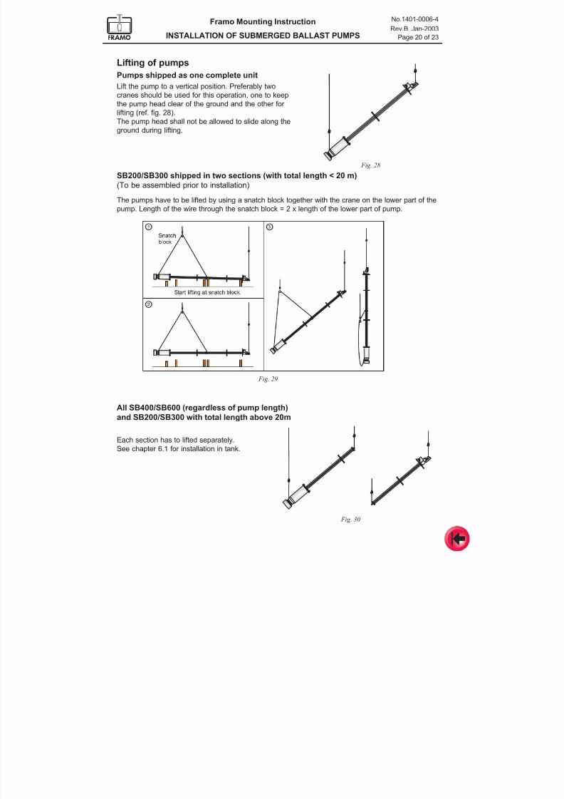
7/16/2019 Pompe Framo
http://slidepdf.com/reader/full/pompe-framo 67/175
Framo Mounting Instruction
INSTALLATION OF SUBMERGED BALLAST PUMPS
No.1401-0006-4
Rev.B Jan-2003
Page 20 of 23
Lifting of pumps
Pumps shipped as one complete unit
Lift the pump to a vertical position. Preferably two
cranes should be used for this operation, one to keepthe pump head clear of the ground and the other for
lifting (ref. fig. 28).
The pump head shall not be allowed to slide along the
ground during lifting.
Fig. 28
Fig. 29
SB200/SB300 shipped in two sections (with total length < 20 m)
(To be assembled prior to installation)
The pumps have to be lifted by using a snatch block together with the crane on the lower part of thepump. Length of the wire through the snatch block = 2 x length of the lower part of pump.
Fig. 30
All SB400/SB600 (regardless of pump length)
and SB200/SB300 with total length above 20m
Each section has to lifted separately.
See chapter 6.1 for installation in tank.
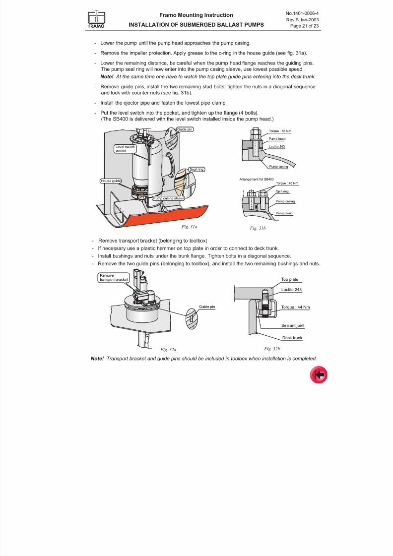
7/16/2019 Pompe Framo
http://slidepdf.com/reader/full/pompe-framo 68/175
Framo Mounting Instruction
INSTALLATION OF SUBMERGED BALLAST PUMPS
No.1401-0006-4
Rev.B Jan-2003
Page 21 of 23
Fig. 32a
- Remove transport bracket (belonging to toolbox)
- If necessary use a plastic hammer on top plate in order to connect to deck trunk.
- Install bushings and nuts under the trunk flange. Tighten bolts in a diagonal sequence.
- Remove the two guide pins (belonging to toolbox), and install the two remaining bushings and nuts.
Fig. 32b
- Lower the pump until the pump head approaches the pump casing.
- Remove the impeller protection. Apply grease to the o-ring in the house guide (see fig. 31a).
- Lower the remaining distance, be careful when the pump head flange reaches the guiding pins.
The pump seal ring will now enter into the pump casing sleeve, use lowest possible speed. Note! At the same time one have to watch the top plate guide pins entering into the deck trunk.
- Remove guide pins, install the two remaining stud bolts, tighten the nuts in a diagonal sequence
and lock with counter nuts (see fig. 31b).
- Install the ejector pipe and fasten the lowest pipe clamp.
- Put the level switch into the pocket, and tighten up the flange (4 bolts).
(The SB400 is delivered with the level switch installed inside the pump head.)
Fig. 31a Fig. 31b
Note! Transport bracket and guide pins should be included in toolbox when installation is completed.
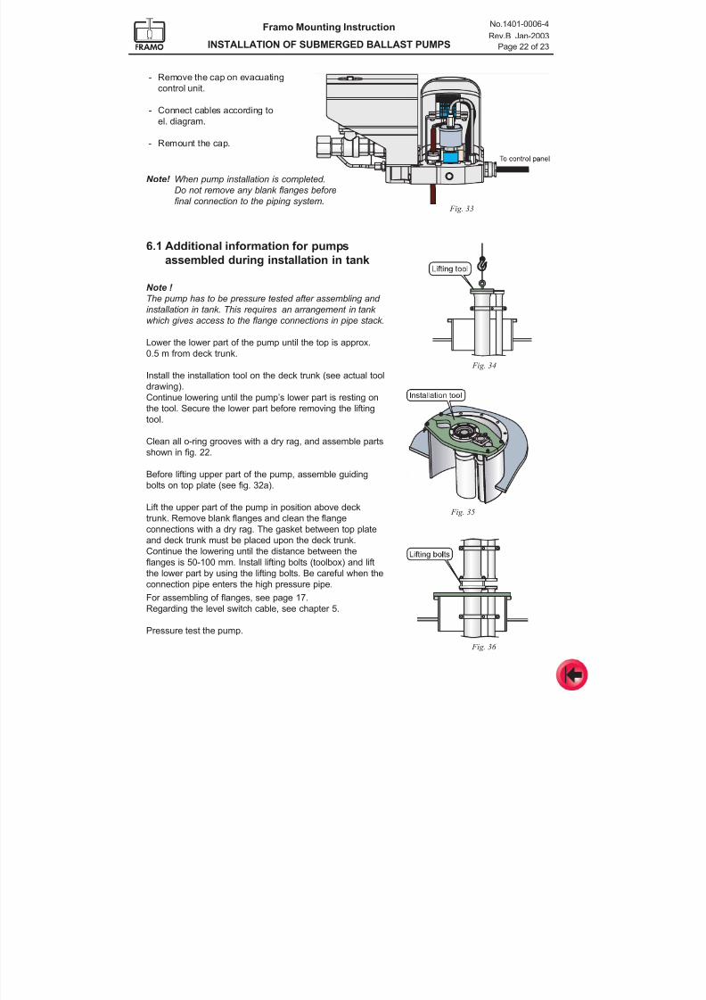
7/16/2019 Pompe Framo
http://slidepdf.com/reader/full/pompe-framo 69/175
Framo Mounting Instruction
INSTALLATION OF SUBMERGED BALLAST PUMPS
No.1401-0006-4
Rev.B Jan-2003
Page 22 of 23
6.1 Additional information for pumpsassembled during installation in tank
Note !
The pump has to be pressure tested after assembling and
installation in tank. This requires an arrangement in tank
which gives access to the flange connections in pipe stack.
Lower the lower part of the pump until the top is approx.
0.5 m from deck trunk.
Install the installation tool on the deck trunk (see actual tool
drawing).
Continue lowering until the pump’s lower part is resting on
the tool. Secure the lower part before removing the lifting
tool.
Clean all o-ring grooves with a dry rag, and assemble parts
shown in fig. 22.
Before lifting upper part of the pump, assemble guiding
bolts on top plate (see fig. 32a).
Lift the upper part of the pump in position above deck
trunk. Remove blank flanges and clean the flange
connections with a dry rag. The gasket between top plate
and deck trunk must be placed upon the deck trunk.
Continue the lowering until the distance between the
flanges is 50-100 mm. Install lifting bolts (toolbox) and lift
the lower part by using the lifting bolts. Be careful when the
connection pipe enters the high pressure pipe.
For assembling of flanges, see page 17.
Regarding the level switch cable, see chapter 5.
Pressure test the pump.
Fig. 34
Fig. 35
- Remove the cap on evacuating
control unit.
- Connect cables according to
el. diagram.
- Remount the cap.
Note! When pump installation is completed.
Do not remove any blank flanges before
final connection to the piping system. Fig. 33
Fig. 36
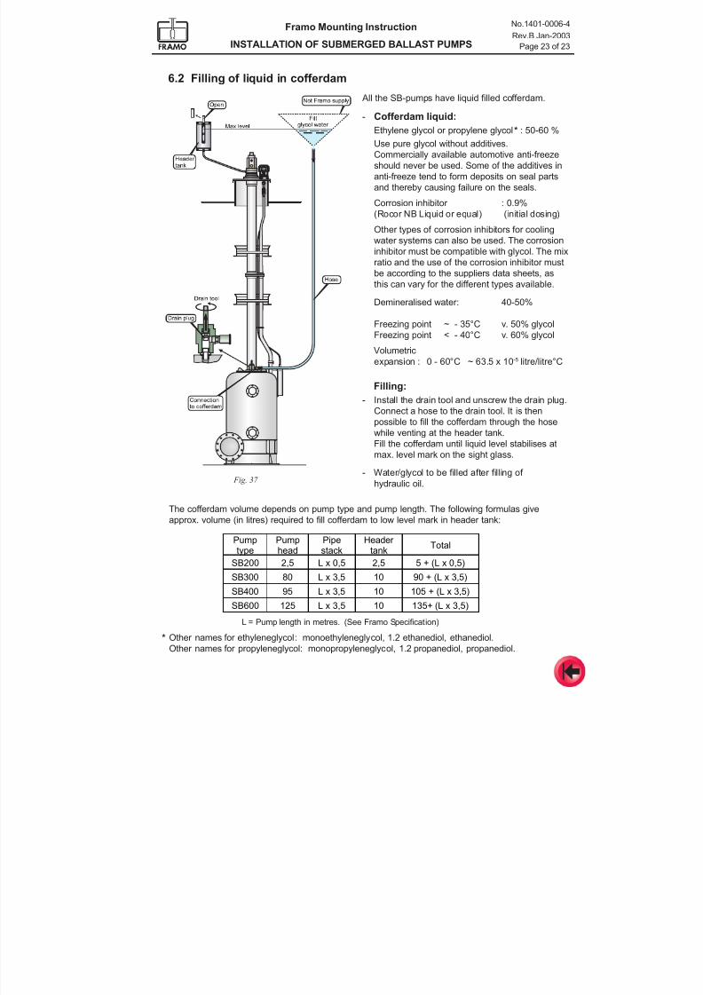
7/16/2019 Pompe Framo
http://slidepdf.com/reader/full/pompe-framo 70/175
Framo Mounting Instruction
INSTALLATION OF SUBMERGED BALLAST PUMPS
No.1401-0006-4
Rev.B Jan-2003
Page 23 of 23
6.2 Filling of liquid in cofferdam
L = Pump length in metres. (See Framo Specification)
Pumptype
Pumphead
Pipestack
Header tank
Total
SB200 2,5 L x 0,5 2,5 5 + (L x 0,5)
SB300 80 L x 3,5 10 90 + (L x 3,5)
SB400 95 L x 3,5 10 105 + (L x 3,5)
SB600 125 L x 3,5 10 135+ (L x 3,5)
Fig. 37
The cofferdam volume depends on pump type and pump length. The following formulas give
approx. volume (in litres) required to fill cofferdam to low level mark in header tank:
All the SB-pumps have liquid filled cofferdam.
- Cofferdam liquid:
Ethylene glycol or propylene glycol* : 50-60 %
Use pure glycol without additives.
Commercially available automotive anti-freeze
should never be used. Some of the additives in
anti-freeze tend to form deposits on seal parts
and thereby causing failure on the seals.
Corrosion inhibitor : 0.9%
(Rocor NB Liquid or equal) (initial dosing)
Other types of corrosion inhibitors for cooling
water systems can also be used. The corrosion
inhibitor must be compatible with glycol. The mix
ratio and the use of the corrosion inhibitor must
be according to the suppliers data sheets, as
this can vary for the different types available.
Demineralised water: 40-50%
Freezing point ~ - 35°C v. 50% glycol
Freezing point < - 40°C v. 60% glycol
Volumetric
expansion : 0 - 60°C ~ 63.5 x 10⁻⁵ litre/litre°C
Filling:
- Install the drain tool and unscrew the drain plug.
Connect a hose to the drain tool. It is then
possible to fill the cofferdam through the hose
while venting at the header tank.
Fill the cofferdam until liquid level stabilises at
max. level mark on the sight glass.
- Water/glycol to be filled after filling of
hydraulic oil.
* Other names for ethyleneglycol: monoethyleneglycol, 1.2 ethanediol, ethanediol.
Other names for propyleneglycol: monopropyleneglycol, 1.2 propanediol, propanediol.
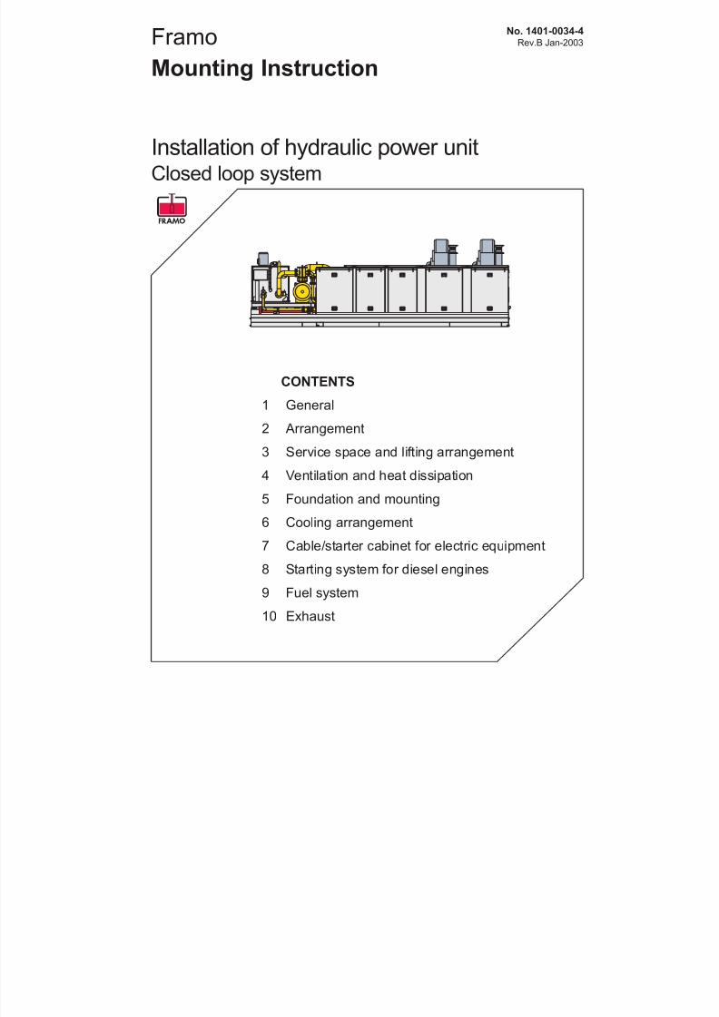
7/16/2019 Pompe Framo
http://slidepdf.com/reader/full/pompe-framo 71/175
Framo
Mounting Instruction
No. 1401-0034-4Rev.B Jan-2003
Installation of hydraulic power unitClosed loop system
CONTENTS
1 General
2 Arrangement
3 Service space and lifting arrangement
4 Ventilation and heat dissipation
5 Foundation and mounting6 Cooling arrangement
7 Cable/starter cabinet for electric equipment
8 Starting system for diesel engines
9 Fuel system
10 Exhaust
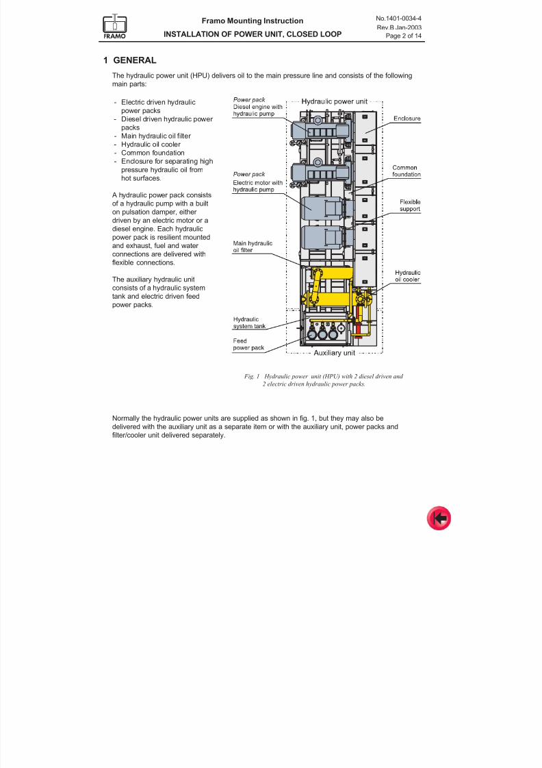
7/16/2019 Pompe Framo
http://slidepdf.com/reader/full/pompe-framo 72/175
Framo Mounting Instruction
INSTALLATION OF POWER UNIT, CLOSED LOOP
No.1401-0034-4
Rev.B Jan-2003
Page 2 of 14
1 GENERAL
The hydraulic power unit (HPU) delivers oil to the main pressure line and consists of the following
main parts:
Fig. 1 Hydraulic power unit (HPU) with 2 diesel driven and
2 electric driven hydraulic power packs.
Normally the hydraulic power units are supplied as shown in fig. 1, but they may also be
delivered with the auxiliary unit as a separate item or with the auxiliary unit, power packs and
filter/cooler unit delivered separately.
- Electric driven hydraulic
power packs
- Diesel driven hydraulic power
packs
- Main hydraulic oil filter
- Hydraulic oil cooler
- Common foundation
- Enclosure for separating high
pressure hydraulic oil from
hot surfaces.
A hydraulic power pack consists
of a hydraulic pump with a built
on pulsation damper, either
driven by an electric motor or a
diesel engine. Each hydraulic
power pack is resilient mounted
and exhaust, fuel and water
connections are delivered with
flexible connections.
The auxiliary hydraulic unit
consists of a hydraulic system
tank and electric driven feed
power packs.
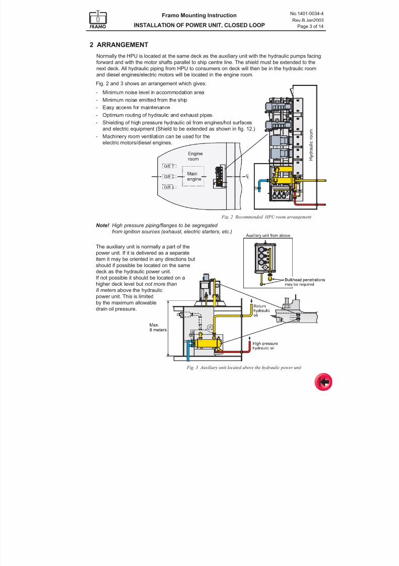
7/16/2019 Pompe Framo
http://slidepdf.com/reader/full/pompe-framo 73/175
Framo Mounting Instruction
INSTALLATION OF POWER UNIT, CLOSED LOOP
No.1401-0034-4
Rev.B Jan2003
Page 3 of 14
2 ARRANGEMENT
Normally the HPU is located at the same deck as the auxiliary unit with the hydraulic pumps facing
forward and with the motor shafts parallel to ship centre line. The shield must be extended to the
next deck. All hydraulic piping from HPU to consumers on deck will then be in the hydraulic roomand diesel engines/electric motors will be located in the engine room.
Fig. 3 Auxiliary unit located above the hydraulic power unit
The auxiliary unit is normally a part of the
power unit. If it is delivered as a separate
item it may be oriented in any directions but
should if possible be located on the same
deck as the hydraulic power unit.
If not possible it should be located on ahigher deck level but not more than
8 meters above the hydraulic
power unit. This is limited
by the maximum allowable
drain oil pressure.
Fig. 2 Recommended HPU room arrangement
Fig. 2 and 3 shows an arrangement which gives:
- Minimum noise level in accommodation area
- Minimum noise emitted from the ship
- Easy access for maintenance
- Optimum routing of hydraulic and exhaust pipes.
- Shielding of high pressure hydraulic oil from engines/hot surfaces
and electric equipment (Shield to be extended as shown in fig. 12.)
- Machinery room ventilation can be used for the
electric motors/diesel engines.
Note! High pressure piping/flanges to be segregated
from ignition sources (exhaust, electric starters, etc.)
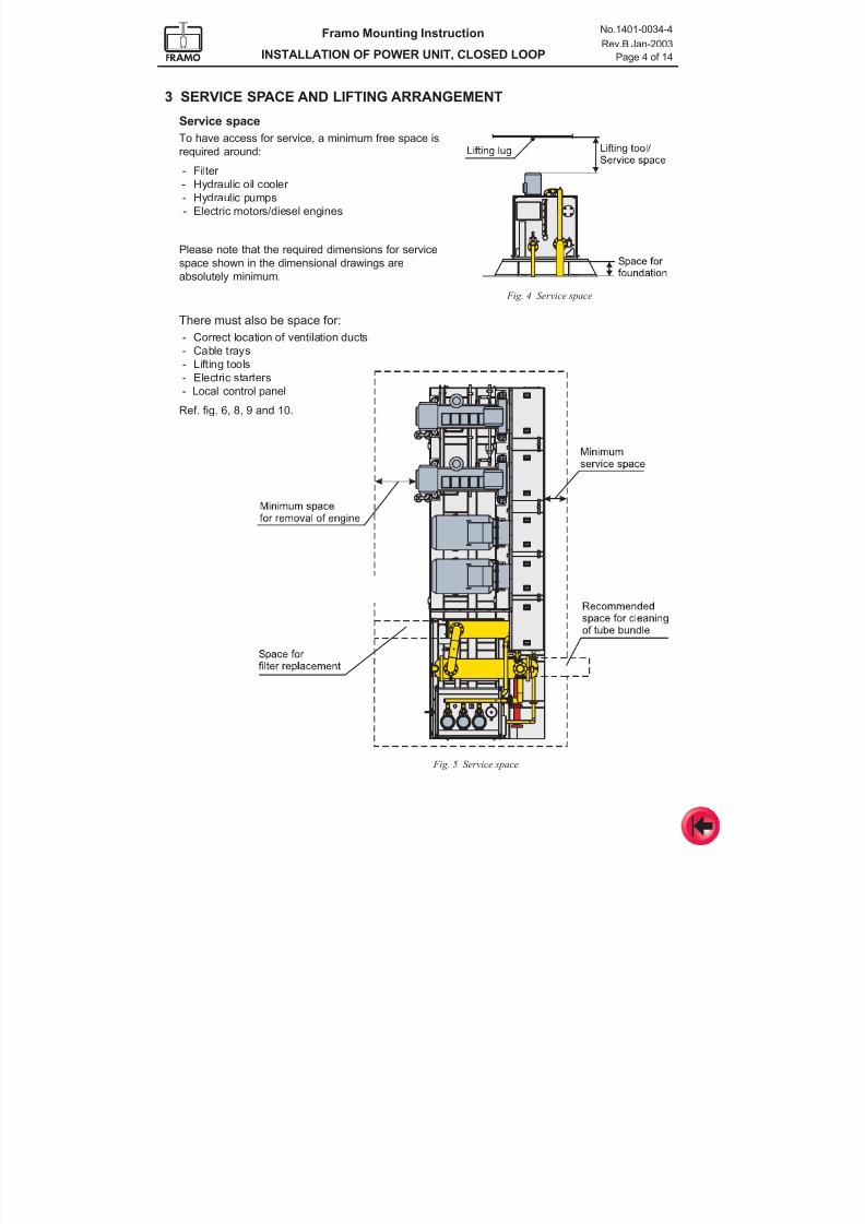
7/16/2019 Pompe Framo
http://slidepdf.com/reader/full/pompe-framo 74/175
Framo Mounting Instruction
INSTALLATION OF POWER UNIT, CLOSED LOOP
No.1401-0034-4
Rev.B Jan-2003
Page 4 of 14
3 SERVICE SPACE AND LIFTING ARRANGEMENT
Fig. 4 Service space
Fig. 5 Service space
Service space
To have access for service, a minimum free space is
required around:
- Filter
- Hydraulic oil cooler
- Hydraulic pumps
- Electric motors/diesel engines
Please note that the required dimensions for service
space shown in the dimensional drawings are
absolutely minimum.
There must also be space for:
- Correct location of ventilation ducts
- Cable trays
- Lifting tools
- Electric starters
- Local control panel
Ref. fig. 6, 8, 9 and 10.
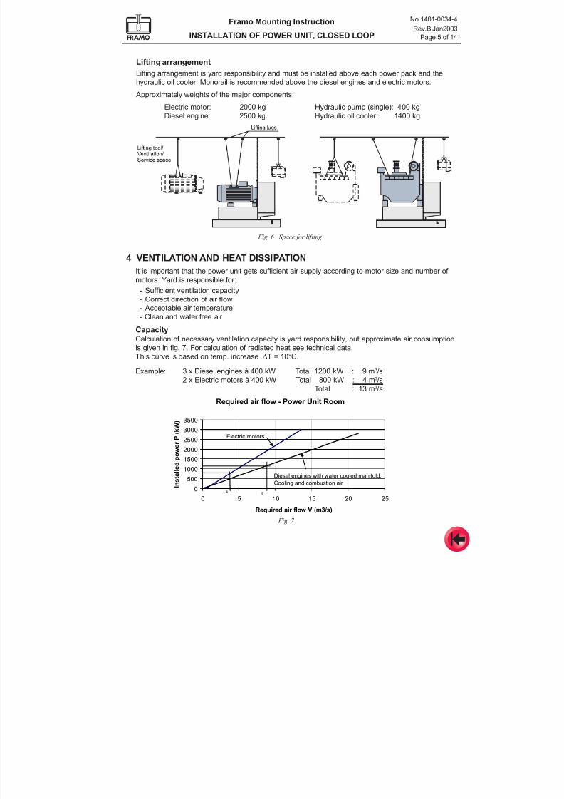
7/16/2019 Pompe Framo
http://slidepdf.com/reader/full/pompe-framo 75/175
Framo Mounting Instruction
INSTALLATION OF POWER UNIT, CLOSED LOOP
No.1401-0034-4
Rev.B Jan2003
Page 5 of 14
Required air flow - Power Unit Room
0
500
1000
1500
2000
2500
3000
3500
0 5 10 15 20 25
Required air flow V (m3/s)
I n s t a l l e d p o w e r P ( k W )
Electric motors
Diesel engines with water cooled manifold.
Cooling and combustion air
49
4 VENTILATION AND HEAT DISSIPATION
It is important that the power unit gets sufficient air supply according to motor size and number of
motors. Yard is responsible for:
- Sufficient ventilation capacity
- Correct direction of air flow
- Acceptable air temperature
- Clean and water free air
CapacityCalculation of necessary ventilation capacity is yard responsibility, but approximate air consumption
is given in fig. 7. For calculation of radiated heat see technical data.
This curve is based on temp. increase ∆T = 10°C.
Fig. 6 Space for lifting
Lifting arrangement
Lifting arrangement is yard responsibility and must be installed above each power pack and the
hydraulic oil cooler. Monorail is recommended above the diesel engines and electric motors.
Approximately weights of the major components:
Electric motor: 2000 kg Hydraulic pump (single): 400 kg
Diesel engine: 2500 kg Hydraulic oil cooler: 1400 kg
Example: 3 x Diesel engines à 400 kW Total 1200 kW : 9 m3/s
2 x Electric motors à 400 kW Total 800 kW : 4 m3/s
Total : 13 m3/s
Fig. 7
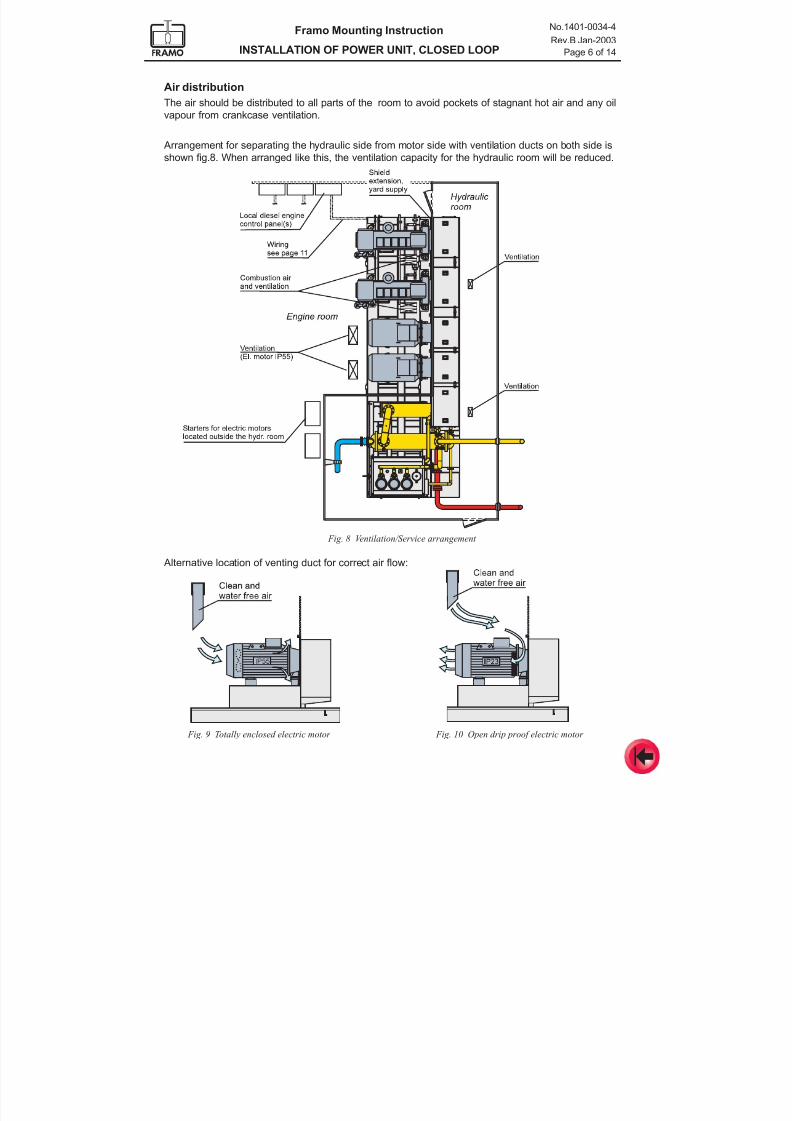
7/16/2019 Pompe Framo
http://slidepdf.com/reader/full/pompe-framo 76/175
Framo Mounting Instruction
INSTALLATION OF POWER UNIT, CLOSED LOOP
No.1401-0034-4
Rev.B Jan-2003
Page 6 of 14
Fig. 8 Ventilation/Service arrangement
Fig. 9 Totally enclosed electric motor Fig. 10 Open drip proof electric motor
Alternative location of venting duct for correct air flow:
Air distribution
The air should be distributed to all parts of the room to avoid pockets of stagnant hot air and any oil
vapour from crankcase ventilation.
Arrangement for separating the hydraulic side from motor side with ventilation ducts on both side is
shown fig.8. When arranged like this, the ventilation capacity for the hydraulic room will be reduced.
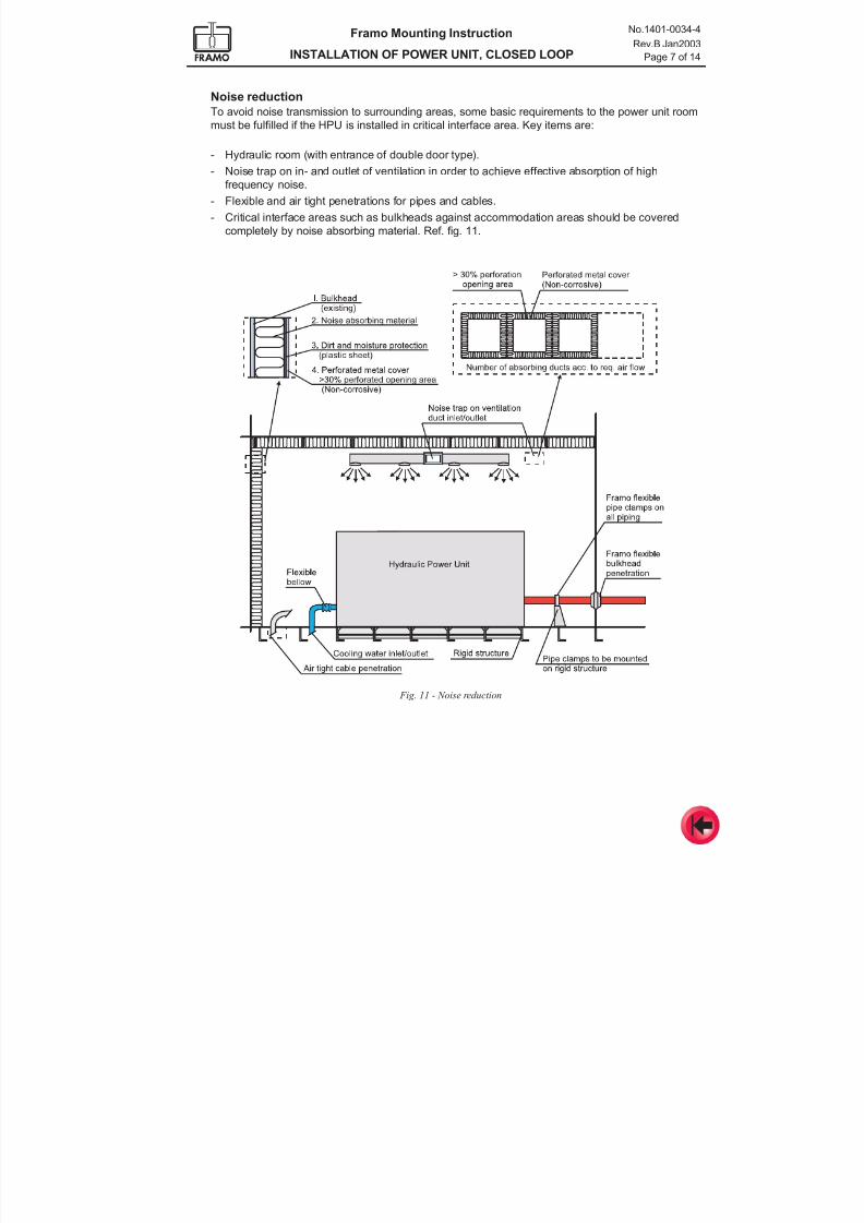
7/16/2019 Pompe Framo
http://slidepdf.com/reader/full/pompe-framo 77/175
Framo Mounting Instruction
INSTALLATION OF POWER UNIT, CLOSED LOOP
No.1401-0034-4
Rev.B Jan2003
Page 7 of 14
Noise reduction
To avoid noise transmission to surrounding areas, some basic requirements to the power unit room
must be fulfilled if the HPU is installed in critical interface area. Key items are:
- Hydraulic room (with entrance of double door type).
- Noise trap on in- and outlet of ventilation in order to achieve effective absorption of high
frequency noise.
- Flexible and air tight penetrations for pipes and cables.
- Critical interface areas such as bulkheads against accommodation areas should be covered
completely by noise absorbing material. Ref. fig. 11.
Fig. 11 - Noise reduction
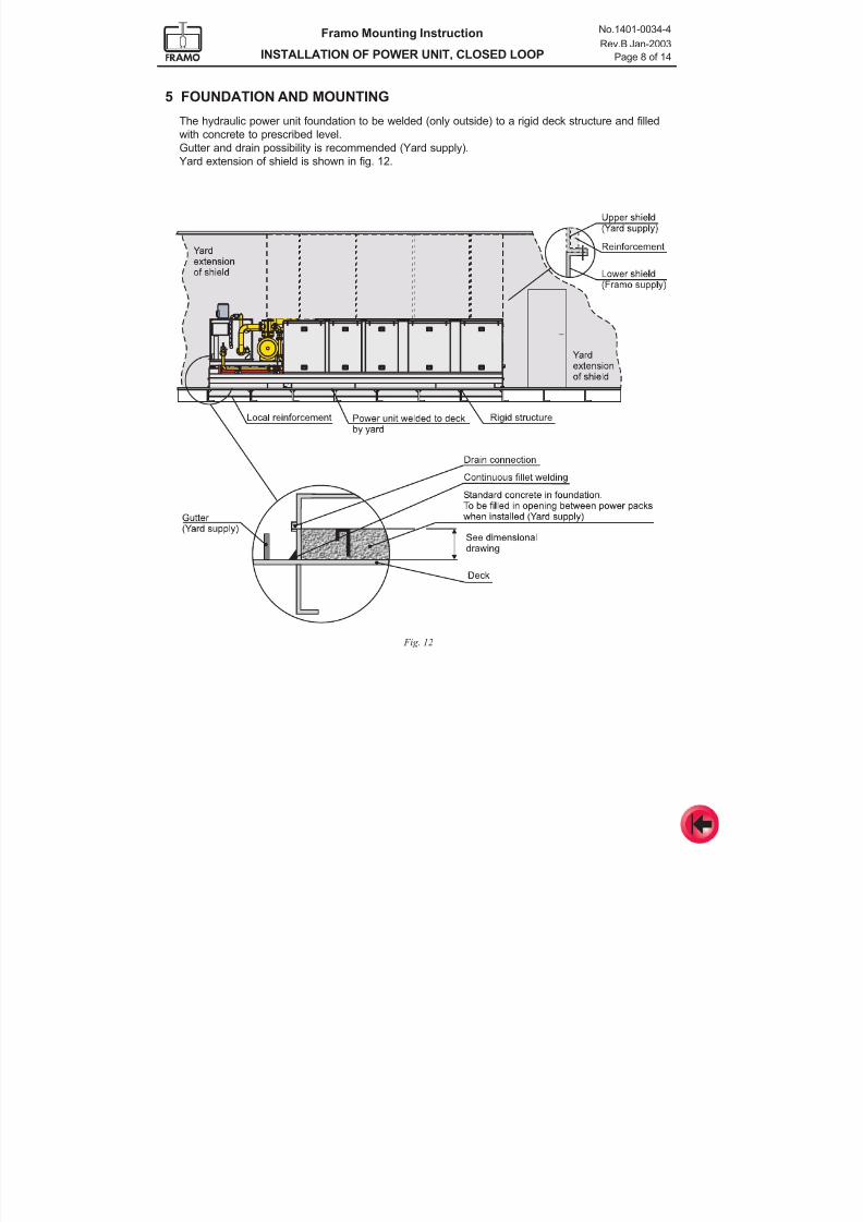
7/16/2019 Pompe Framo
http://slidepdf.com/reader/full/pompe-framo 78/175
Framo Mounting Instruction
INSTALLATION OF POWER UNIT, CLOSED LOOP
No.1401-0034-4
Rev.B Jan-2003
Page 8 of 14
5 FOUNDATION AND MOUNTING
The hydraulic power unit foundation to be welded (only outside) to a rigid deck structure and filled
with concrete to prescribed level.
Gutter and drain possibility is recommended (Yard supply).Yard extension of shield is shown in fig. 12.
Fig. 12
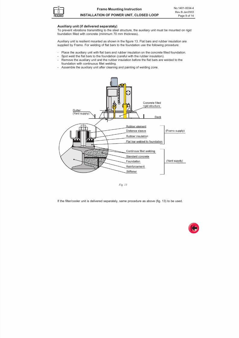
7/16/2019 Pompe Framo
http://slidepdf.com/reader/full/pompe-framo 79/175
Framo Mounting Instruction
INSTALLATION OF POWER UNIT, CLOSED LOOP
No.1401-0034-4
Rev.B Jan2003
Page 9 of 14
Auxiliary unit (if delivered separately)To prevent vibrations transmitting to the steel structure, the auxiliary unit must be mounted on rigid
foundation filled with concrete (minimum 70 mm thickness).
Auxiliary unit is resilient mounted as shown in the figure 13. Flat bars and rubber insulation aresupplied by Framo. For welding of flat bars to the foundation use the following procedure:
- Place the auxiliary unit with flat bars and rubber insulation on the concrete filled foundation.
- Spot weld the flat bars to the foundation (careful with the rubber insulation).
- Remove the auxiliary unit and the rubber insulation before the flat bars are welded to the
foundation with continuous fillet welding.
- Assemble the auxiliary unit after cleaning and painting of welding zone.
Fig. 13
If the filter/cooler unit is delivered separately, same procedure as above (fig. 13) to be used.
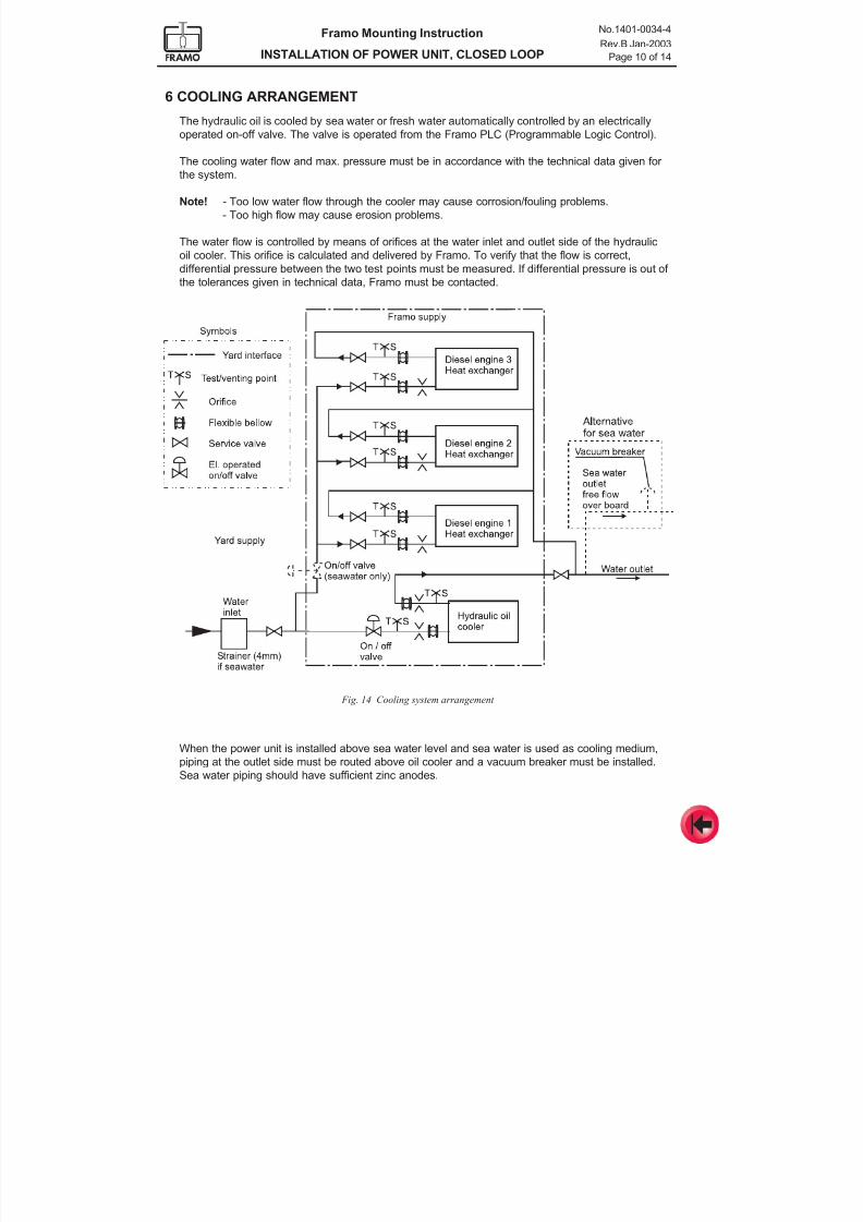
7/16/2019 Pompe Framo
http://slidepdf.com/reader/full/pompe-framo 80/175
Framo Mounting Instruction
INSTALLATION OF POWER UNIT, CLOSED LOOP
No.1401-0034-4
Rev.B Jan-2003
Page 10 of 14
6 COOLING ARRANGEMENT
The hydraulic oil is cooled by sea water or fresh water automatically controlled by an electrically
operated on-off valve. The valve is operated from the Framo PLC (Programmable Logic Control).
The cooling water flow and max. pressure must be in accordance with the technical data given for
the system.
Note! - Too low water flow through the cooler may cause corrosion/fouling problems.
- Too high flow may cause erosion problems.
The water flow is controlled by means of orifices at the water inlet and outlet side of the hydraulic
oil cooler. This orifice is calculated and delivered by Framo. To verify that the flow is correct,
differential pressure between the two test points must be measured. If differential pressure is out of
the tolerances given in technical data, Framo must be contacted.
When the power unit is installed above sea water level and sea water is used as cooling medium,
piping at the outlet side must be routed above oil cooler and a vacuum breaker must be installed.
Sea water piping should have sufficient zinc anodes.
Fig. 14 Cooling system arrangement
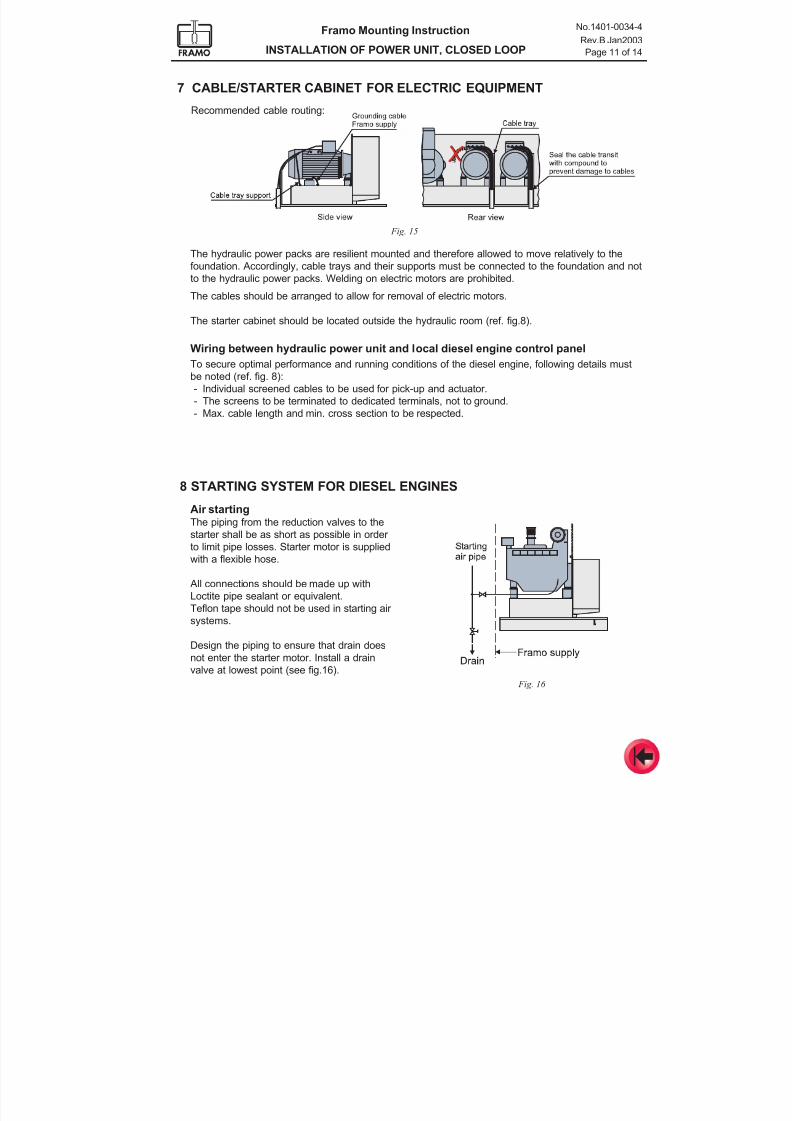
7/16/2019 Pompe Framo
http://slidepdf.com/reader/full/pompe-framo 81/175
Framo Mounting Instruction
INSTALLATION OF POWER UNIT, CLOSED LOOP
No.1401-0034-4
Rev.B Jan2003
Page 11 of 14
7 CABLE/STARTER CABINET FOR ELECTRIC EQUIPMENT
Recommended cable routing:
Fig. 15
The hydraulic power packs are resilient mounted and therefore allowed to move relatively to the
foundation. Accordingly, cable trays and their supports must be connected to the foundation and not
to the hydraulic power packs. Welding on electric motors are prohibited.
The cables should be arranged to allow for removal of electric motors.
The starter cabinet should be located outside the hydraulic room (ref. fig.8).
Wiring between hydraulic power unit and local diesel engine control panel
To secure optimal performance and running conditions of the diesel engine, following details must
be noted (ref. fig. 8):
- Individual screened cables to be used for pick-up and actuator.
- The screens to be terminated to dedicated terminals, not to ground.
- Max. cable length and min. cross section to be respected.
8 STARTING SYSTEM FOR DIESEL ENGINES
Air startingThe piping from the reduction valves to the
starter shall be as short as possible in order
to limit pipe losses. Starter motor is supplied
with a flexible hose.
All connections should be made up with
Loctite pipe sealant or equivalent.
Teflon tape should not be used in starting air
systems.
Design the piping to ensure that drain does
not enter the starter motor. Install a drain
valve at lowest point (see fig.16).
Fig. 16
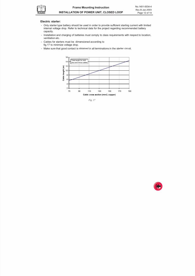
7/16/2019 Pompe Framo
http://slidepdf.com/reader/full/pompe-framo 82/175
Framo Mounting Instruction
INSTALLATION OF POWER UNIT, CLOSED LOOP
No.1401-0034-4
Rev.B Jan-2003
Page 12 of 14
2
4
6
8
10
12
14
16
70 90 110 130 150 170 190
Cable cross section (mm2, copper)
C a b l e l e n g h t ( m )
Total lenght for both
plus and minus cables
Electric starter:
- Only starter type battery should be used in order to provide sufficient starting current with limited
internal voltage drop. Refer to technical data for the project regarding recommended battery
capacity.
- Installation and charging of batteries must comply to class requirements with respect to location,
ventilation etc.
- Cables for starters must be dimensioned according to
fig.17 to minimize voltage drop.
- Make sure that good contact is obtained in all terminations in the starter circuit.
Fig. 17
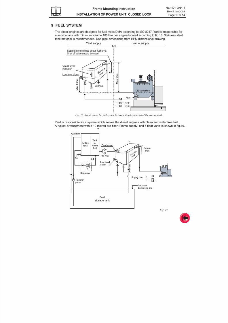
7/16/2019 Pompe Framo
http://slidepdf.com/reader/full/pompe-framo 83/175
Framo Mounting Instruction
INSTALLATION OF POWER UNIT, CLOSED LOOP
No.1401-0034-4
Rev.B Jan2003
Page 13 of 14
9 FUEL SYSTEM
The diesel engines are designed for fuel types DMA according to ISO 8217. Yard is responsible for
a service tank with minimum volume 100 litre per engine located according to fig.18. Stainless steel
tank material is recommended. Use pipe dimensions from HPU dimensional drawing.
Fig. 18 Requirement for fuel system between diesel engines and the service tank.
Yard is responsible for a system which serves the diesel engines with clean and water free fuel.
A typical arrangement with a 10 micron pre-filter (Framo supply) and a float valve is shown in fig.19.
Fig. 19
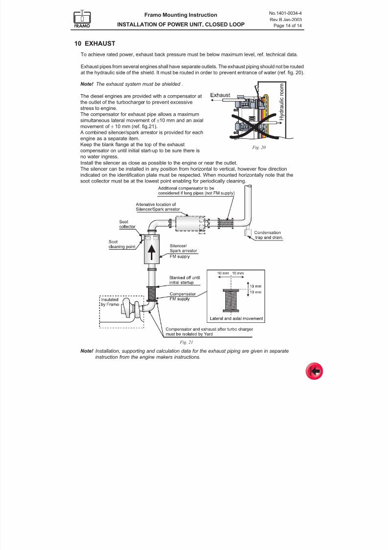
7/16/2019 Pompe Framo
http://slidepdf.com/reader/full/pompe-framo 84/175
Framo Mounting Instruction
INSTALLATION OF POWER UNIT, CLOSED LOOP
No.1401-0034-4
Rev.B Jan-2003
Page 14 of 14
10 EXHAUST
To achieve rated power, exhaust back pressure must be below maximum level, ref. technical data.
Exhaust pipes from several engines shall have separate outlets. The exhaust piping should not be routedat the hydraulic side of the shield. It must be routed in order to prevent entrance of water (ref. fig. 20).
Fig. 21
Note! Installation, supporting and calculation data for the exhaust piping are given in separate
instruction from the engine makers instructions.
Note! The exhaust system must be shielded .
The diesel engines are provided with a compensator at
the outlet of the turbocharger to prevent excessive
stress to engine.
The compensator for exhaust pipe allows a maximum
simultaneous lateral movement of ±10 mm and an axial
movement of ± 10 mm (ref. fig.21).
A combined silencer/spark arrestor is provided for each
engine as a separate item.
Keep the blank flange at the top of the exhaust
compensator on until initial start-up to be sure there is
no water ingress.
Fig. 20
Install the silencer as close as possible to the engine or near the outlet.
The silencer can be installed in any position from horizontal to vertical, however flow direction
indicated on the identification plate must be respected. When mounted horizontally note that the
soot collector must be at the lowest point enabling for periodically cleaning.
7/16/2019 Pompe Framo
http://slidepdf.com/reader/full/pompe-framo 85/175
Framo
Mounting Instruction
Installation of electrical equipment
No. 1401-0009-4 Apr-2000
1 Framo control panel
2 Motor starters2.1 Power pack starter
2.2 Feed pump starter (closed loop system only)
3 Electric motors
4 STC remote control valve
5 Interface to vessel´s integrated control system
6 Preservation
CONTENTS
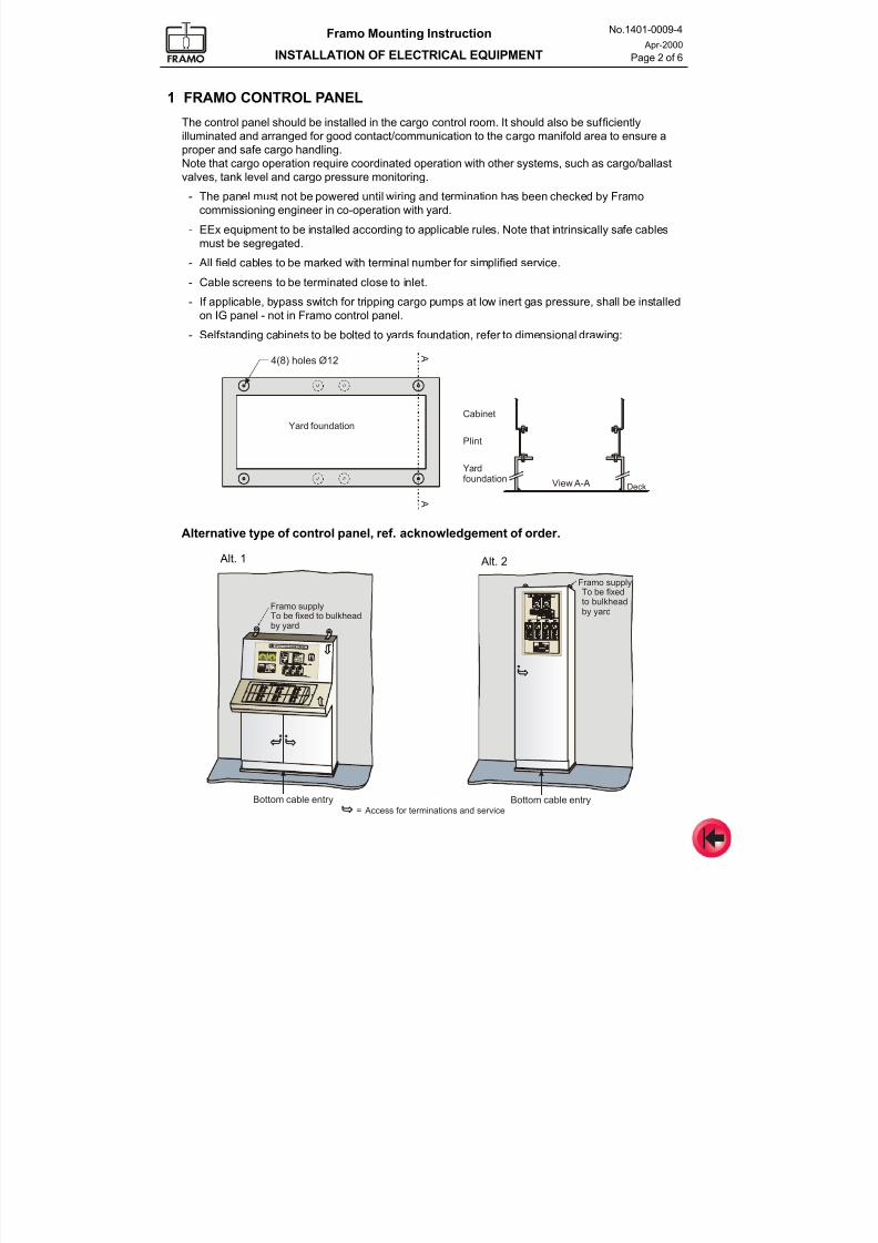
7/16/2019 Pompe Framo
http://slidepdf.com/reader/full/pompe-framo 86/175
Framo Mounting Instruction
INSTALLATION OF ELECTRICAL EQUIPMENT
No.1401-0009-4
Apr-2000
Page 2 of 6
1 FRAMO CONTROL PANEL
The control panel should be installed in the cargo control room. It should also be sufficiently
illuminated and arranged for good contact/communication to the cargo manifold area to ensure a
proper and safe cargo handling.Note that cargo operation require coordinated operation with other systems, such as cargo/ballast
valves, tank level and cargo pressure monitoring.
- The panel must not be powered until wiring and termination has been checked by Framo
commissioning engineer in co-operation with yard.
- EEx equipment to be installed according to applicable rules. Note that intrinsically safe cables
must be segregated.
- All field cables to be marked with terminal number for simplified service.
- Cable screens to be terminated close to inlet.
- If applicable, bypass switch for tripping cargo pumps at low inert gas pressure, shall be installedon IG panel - not in Framo control panel.
- Selfstanding cabinets to be bolted to yards foundation, refer to dimensional drawing:
Alt. 1 Alt. 2
Alternative type of control panel, ref. acknowledgement of order.
Framo supply
Bottom cable entry Access for terminations and service=
Framo supplyTo be fixedto bulkhead
by yardTo be fixed to bulkheadby yard
Bottom cable entry
Cabinet
A
A
Yard foundation
Plint
Yardfoundation
View A-A Deck
4(8) holes Ø12
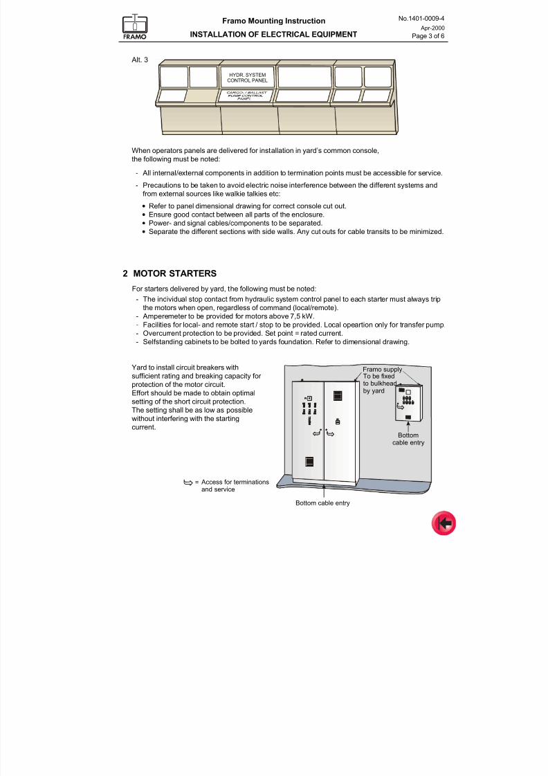
7/16/2019 Pompe Framo
http://slidepdf.com/reader/full/pompe-framo 87/175
Framo Mounting Instruction
INSTALLATION OF ELECTRICAL EQUIPMENT
No.1401-0009-4
Apr-2000
Page 3 of 6
2 MOTOR STARTERS
For starters delivered by yard, the following must be noted:
- The individual stop contact from hydraulic system control panel to each starter must always trip
the motors when open, regardless of command (local/remote).
- Amperemeter to be provided for motors above 7,5 kW.
- Facilities for local- and remote start / stop to be provided. Local opeartion only for transfer pump.
- Overcurrent protection to be provided. Set point = rated current.
- Selfstanding cabinets to be bolted to yards foundation. Refer to dimensional drawing.
Alt. 3
When operators panels are delivered for installation in yard’s common console,
the following must be noted:
- All internal/external components in addition to termination points must be accessible for service.
- Precautions to be taken to avoid electric noise interference between the different systems and
from external sources like walkie talkies etc:
• Refer to panel dimensional drawing for correct console cut out.
• Ensure good contact between all parts of the enclosure.
• Power- and signal cables/components to be separated.
• Separate the different sections with side walls. Any cut outs for cable transits to be minimized.
Framo supply
Bottom cable entry
Bottomcable entry
= Access for terminationsand service
To be fixed
to bulkheadby yard
HYDR. SYSTEMCONTROL PANEL
Yard to install circuit breakers with
sufficient rating and breaking capacity for
protection of the motor circuit.Effort should be made to obtain optimal
setting of the short circuit protection.
The setting shall be as low as possible
without interfering with the starting
current.
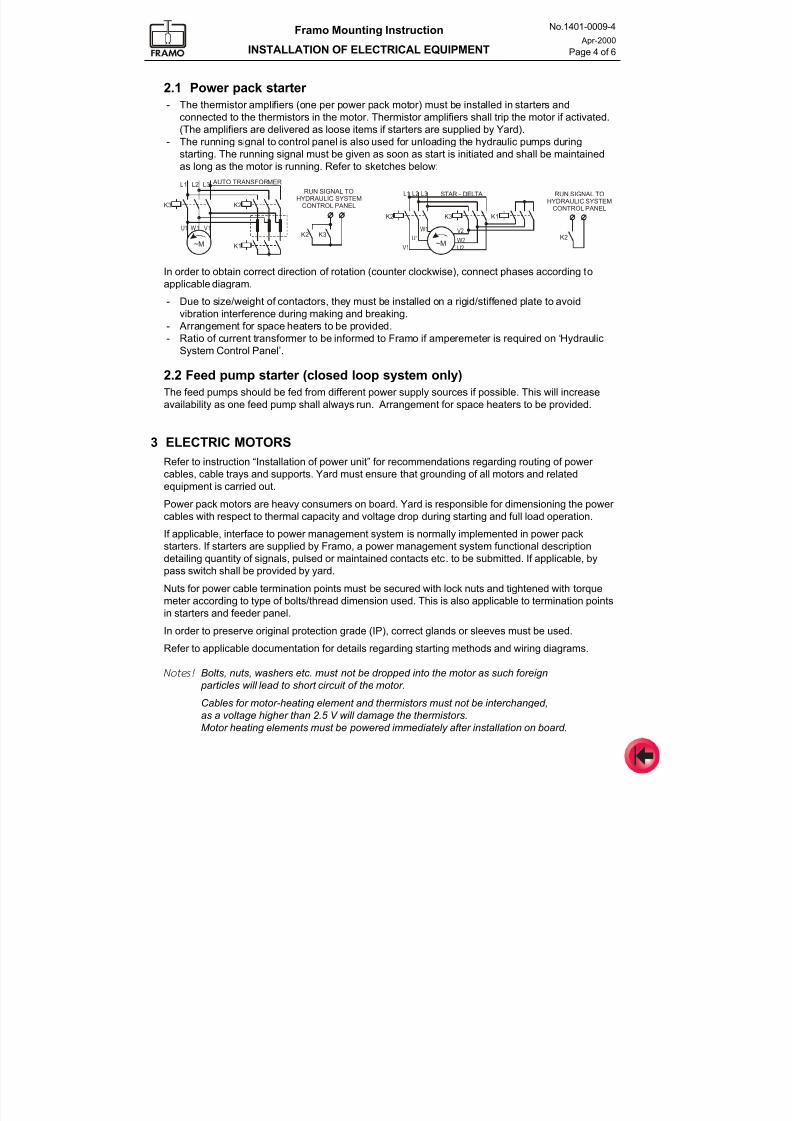
7/16/2019 Pompe Framo
http://slidepdf.com/reader/full/pompe-framo 88/175
Framo Mounting Instruction
INSTALLATION OF ELECTRICAL EQUIPMENT
No.1401-0009-4
Apr-2000
Page 4 of 6
3 ELECTRIC MOTORS
Refer to instruction “Installation of power unit” for recommendations regarding routing of power
cables, cable trays and supports. Yard must ensure that grounding of all motors and related
equipment is carried out.
Power pack motors are heavy consumers on board. Yard is responsible for dimensioning the power
cables with respect to thermal capacity and voltage drop during starting and full load operation.
If applicable, interface to power management system is normally implemented in power pack
starters. If starters are supplied by Framo, a power management system functional description
detailing quantity of signals, pulsed or maintained contacts etc. to be submitted. If applicable, by
pass switch shall be provided by yard.
Nuts for power cable termination points must be secured with lock nuts and tightened with torque
meter according to type of bolts/thread dimension used. This is also applicable to termination points
in starters and feeder panel.
In order to preserve original protection grade (IP), correct glands or sleeves must be used.
Refer to applicable documentation for details regarding starting methods and wiring diagrams.
Notes! Bolts, nuts, washers etc. must not be dropped into the motor as such foreign
particles will lead to short circuit of the motor.
Cables for motor-heating element and thermistors must not be interchanged,
as a voltage higher than 2.5 V will damage the thermistors.
Motor heating elements must be powered immediately after installation on board.
2.1 Power pack starter
- The thermistor amplifiers (one per power pack motor) must be installed in starters and
connected to the thermistors in the motor. Thermistor amplifiers shall trip the motor if activated.
(The amplifiers are delivered as loose items if starters are supplied by Yard).
- The running signal to control panel is also used for unloading the hydraulic pumps duringstarting. The running signal must be given as soon as start is initiated and shall be maintained
as long as the motor is running. Refer to sketches below:
In order to obtain correct direction of rotation (counter clockwise), connect phases according toapplicable diagram.
- Due to size/weight of contactors, they must be installed on a rigid/stiffened plate to avoid
vibration interference during making and breaking.
- Arrangement for space heaters to be provided.
- Ratio of current transformer to be informed to Framo if amperemeter is required on ‘Hydraulic
System Control Panel’.
2.2 Feed pump starter (closed loop system only)
The feed pumps should be fed from different power supply sources if possible. This will increase
availability as one feed pump shall always run. Arrangement for space heaters to be provided.
K3
K2 K3
RUN SIGNAL TOHYDRAULIC SYSTEM
CONTROL PANEL
AUTO TRANSFORMER
STAR - DELTA
L1 L2 L3
U1 W 1 V 1
K2
K1~M
K2
K2
RUN SIGNAL TOHYDRAULIC SYSTEM
CONTROL PANEL
L1 L2 L3
U1 W2
W1 V2
V1 U2
K3 K1
~M
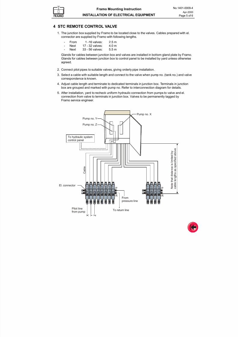
7/16/2019 Pompe Framo
http://slidepdf.com/reader/full/pompe-framo 89/175
Framo Mounting Instruction
INSTALLATION OF ELECTRICAL EQUIPMENT
No.1401-0009-4
Apr-2000
Page 5 of 6
4 STC REMOTE CONTROL VALVE
1. The junction box supplied by Framo to be located close to the valves. Cables prepared with el.
connector are supplied by Framo with following lengths.
- From 1 -16 valves: 2.5 m- Next 17 - 32 valves: 4.0 m
- Next 33 - 56 valves: 5.5 m
Glands for cables between junction box and valves are installed in bottom gland plate by Framo.
Glands for cables between junction box to control panel to be installed by yard unless otherwise
agreed.
2. Connect pilot pipes to suitable valves, giving orderly pipe installation.
3. Select a cable with suitable length and connect to the valve when pump no. (tank no.) and valve
correspondence is known.
4. Adjust cable length and terminate to dedicated terminals in junction box. Terminals in junctionbox are grouped and marked with pump no. Refer to interconnection diagram for details.
5. After installation, yard to recheck uniform hydraulic connection from pumps to valve and el.
connection from valve to terminals in junction box. Valves to be permanently tagged by
Framo service engineer.
El. connector
Pilot linefrom pump
Frompressure line
P P
R R
To return line
X
Cable
Y Z
To hydraulic systemcontrol panel
Notethatdistance
islimitedby
cablelengthsassp
ecifiedabove
Pump no. Y
Pump no. X
Pump no. Z
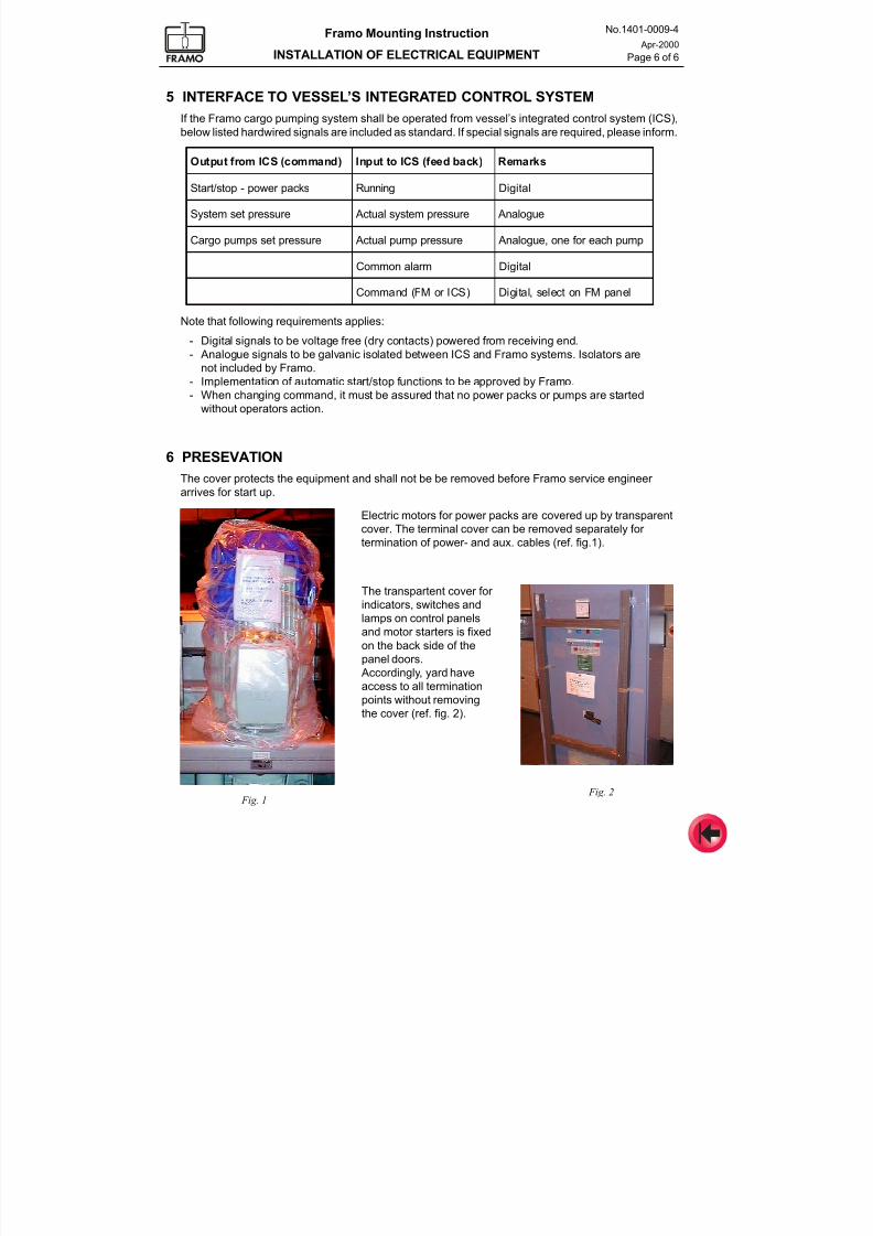
7/16/2019 Pompe Framo
http://slidepdf.com/reader/full/pompe-framo 90/175
Framo Mounting Instruction
INSTALLATION OF ELECTRICAL EQUIPMENT
No.1401-0009-4
Apr-2000
Page 6 of 6
Output from ICS (command) Input to ICS (feed back) Remarks
Start/stop - power packs Running Digital
System set pressure Actual system pressure Analogue
Cargo pumps set pressure Actual pump pressure Analogue, one for each pump
Common alarm Digital
Command (FM or ICS) Digital, select on FM panel
5 INTERFACE TO VESSEL’S INTEGRATED CONTROL SYSTEM
If the Framo cargo pumping system shall be operated from vessel’s integrated control system (ICS),
below listed hardwired signals are included as standard. If special signals are required, please inform.
Note that following requirements applies:
- Digital signals to be voltage free (dry contacts) powered from receiving end.
- Analogue signals to be galvanic isolated between ICS and Framo systems. Isolators are
not included by Framo.
- Implementation of automatic start/stop functions to be approved by Framo.
- When changing command, it must be assured that no power packs or pumps are started
without operators action.
6 PRESEVATIONThe cover protects the equipment and shall not be be removed before Framo service engineer
arrives for start up.
Electric motors for power packs are covered up by transparent
cover. The terminal cover can be removed separately for
termination of power- and aux. cables (ref. fig.1).
Fig. 1 Fig. 2
The transpartent cover for
indicators, switches and
lamps on control panels
and motor starters is fixed
on the back side of the
panel doors.
Accordingly, yard have
access to all termination
points without removing
the cover (ref. fig. 2).
7/16/2019 Pompe Framo
http://slidepdf.com/reader/full/pompe-framo 91/175
Framo
Mounting Instruction
Yard equipment
No. 1401-0010-4
Rev.B Nov-2002
CONTENTS
1 General
2 Hydraulic oil storage / Clean oil drain tank
3 Closing time for cargo valves
4 Hydraulic driven equipmentWinches - Cranes etc.
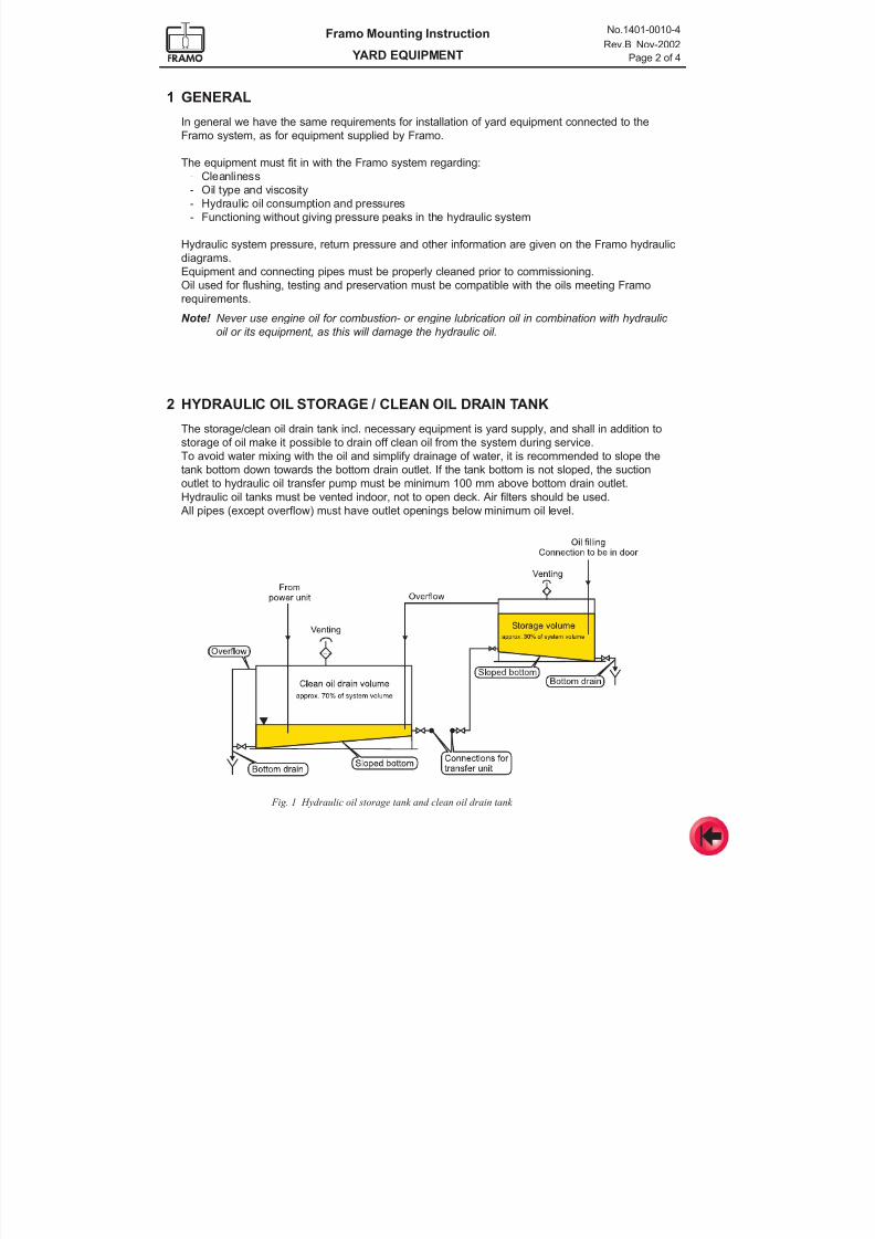
7/16/2019 Pompe Framo
http://slidepdf.com/reader/full/pompe-framo 92/175
Framo Mounting Instruction
YARD EQUIPMENT
No.1401-0010-4
Rev.B Nov-2002
Page 2 of 4
1 GENERAL
In general we have the same requirements for installation of yard equipment connected to the
Framo system, as for equipment supplied by Framo.
The equipment must fit in with the Framo system regarding:
- Cleanliness
- Oil type and viscosity
- Hydraulic oil consumption and pressures
- Functioning without giving pressure peaks in the hydraulic system
Hydraulic system pressure, return pressure and other information are given on the Framo hydraulic
diagrams.
Equipment and connecting pipes must be properly cleaned prior to commissioning.
Oil used for flushing, testing and preservation must be compatible with the oils meeting Framo
requirements.
Note! Never use engine oil for combustion- or engine lubrication oil in combination with hydraulic
oil or its equipment, as this will damage the hydraulic oil.
2 HYDRAULIC OIL STORAGE / CLEAN OIL DRAIN TANK
The storage/clean oil drain tank incl. necessary equipment is yard supply, and shall in addition to
storage of oil make it possible to drain off clean oil from the system during service.
To avoid water mixing with the oil and simplify drainage of water, it is recommended to slope thetank bottom down towards the bottom drain outlet. If the tank bottom is not sloped, the suction
outlet to hydraulic oil transfer pump must be minimum 100 mm above bottom drain outlet.
Hydraulic oil tanks must be vented indoor, not to open deck. Air filters should be used.
All pipes (except overflow) must have outlet openings below minimum oil level.
Fig. 1 Hydraulic oil storage tank and clean oil drain tank
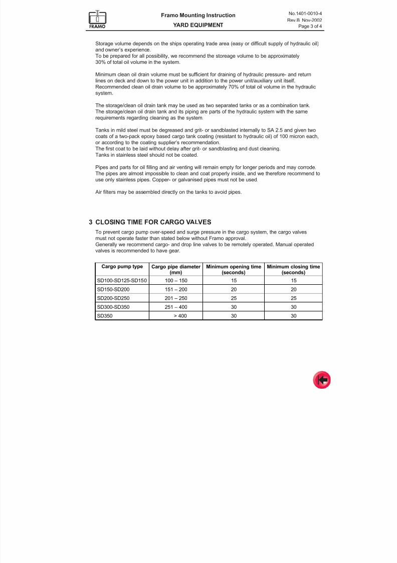
7/16/2019 Pompe Framo
http://slidepdf.com/reader/full/pompe-framo 93/175
Framo Mounting Instruction
YARD EQUIPMENT
No.1401-0010-4
Rev.B Nov-2002
Page 3 of 4
3 CLOSING TIME FOR CARGO VALVES
To prevent cargo pump over-speed and surge pressure in the cargo system, the cargo valves
must not operate faster than stated below without Framo approval.
Generally we recommend cargo- and drop line valves to be remotely operated. Manual operated
valves is recommended to have gear.
Cargo pump type Cargo pipe diameter (mm)
Minimum opening time(seconds)
Minimum closing time(seconds)
SD100-SD125-SD150 100 – 150 15 15
SD150-SD200 151 – 200 20 20
SD200-SD250 201 – 250 25 25
SD300-SD350 251 – 400 30 30
SD350 > 400 30 30
Storage volume depends on the ships operating trade area (easy or difficult supply of hydraulic oil)
and owner’s experience.
To be prepared for all possibility, we recommend the storeage volume to be approximately
30% of total oil volume in the system.
Minimum clean oil drain volume must be sufficient for draining of hydraulic pressure- and return
lines on deck and down to the power unit in addition to the power unit/auxiliary unit itself.
Recommended clean oil drain volume to be approximately 70% of total oil volume in the hydraulic
system.
The storage/clean oil drain tank may be used as two separated tanks or as a combination tank.
The storage/clean oil drain tank and its piping are parts of the hydraulic system with the same
requirements regarding cleaning as the system.
Tanks in mild steel must be degreased and grit- or sandblasted internally to SA 2.5 and given two
coats of a two-pack epoxy based cargo tank coating (resistant to hydraulic oil) of 100 micron each,
or according to the coating supplier’s recommendation.
The first coat to be laid without delay after grit- or sandblasting and dust cleaning.
Tanks in stainless steel should not be coated.
Pipes and parts for oil filling and air venting will remain empty for longer periods and may corrode.
The pipes are almost impossible to clean and coat properly inside, and we therefore recommend to
use only stainless pipes. Copper- or galvanised pipes must not be used.
Air filters may be assembled directly on the tanks to avoid pipes.
7/16/2019 Pompe Framo
http://slidepdf.com/reader/full/pompe-framo 94/175
Framo Mounting Instruction
YARD EQUIPMENT
No.1401-0010-4
Rev.B Nov-2002
Page 4 of 4
4 HYDRAULIC DRIVEN EQUIPMENT – WINCHES, CRANES ETC.
To ensure correct function of the complete system, the yard is responsible for the adaptation of
their equipment connected to the Framo cargo pumping system.
The Framo hydraulic system is operating at constant pressure, and hydraulic oil consumption is not
accepted from any equipment during stand still condition.
In addition to the general requirements, the equipment must comply with the following:
- Separate service valves for each unit’s pressure-, return- and drain line to be included by the
yard, making it possible to do service without stopping the complete system. The valves are to
be installed in the pipelines, not as part of the control valve assembly.
- Manometer test connections must be provided by the yard both on pressure- and return side,
making it possible to do trouble shooting and to check for pressure peaks.
- Air venting valves/plugs must be installed on the highest possible point on both
pressure- and return side of the equipment.
- The equipment must not transmit pressure surges into the system, and must therefore have
possibilities for limiting the response time (flow variation). Accelerating/retarding time from
0 – to maximum and from maximum – to zero oil consumption must be >2,0 seconds.
- The equipment must have a pressure compensated flow limiting valve on the pressure inlet side
to avoid motor over-speed.
- Hydraulic motor housing and shaft sealing system must be designed for a hydraulic return
pressure of minimum 10 bar to avoid separate drain lines.
- Shaft sealing systems must have protection against sea water, air and contaminant intrusion.
- If separate drain lines are installed, drain oil filter with dirty filter indication/alarm to be included
by the yard. Minimum filtration ratio B15
³ 200.
- Separate hydraulic internal reservoirs or drain tanks are not acceptable.
- Generally Framo do not accept hydraulic cylinders connected to the system. For cranes with
hydraulic cylinders, use a separate hydraulic system with a hydraulic motor driven from the
Framo system.
- All equipment must be properly cleaned to meet ISO contamination code 4406 class 15/11 or
better prior to installation. Oil used for cleaning, testing and preservation must be compatible
with the oils meeting Framo requirements.
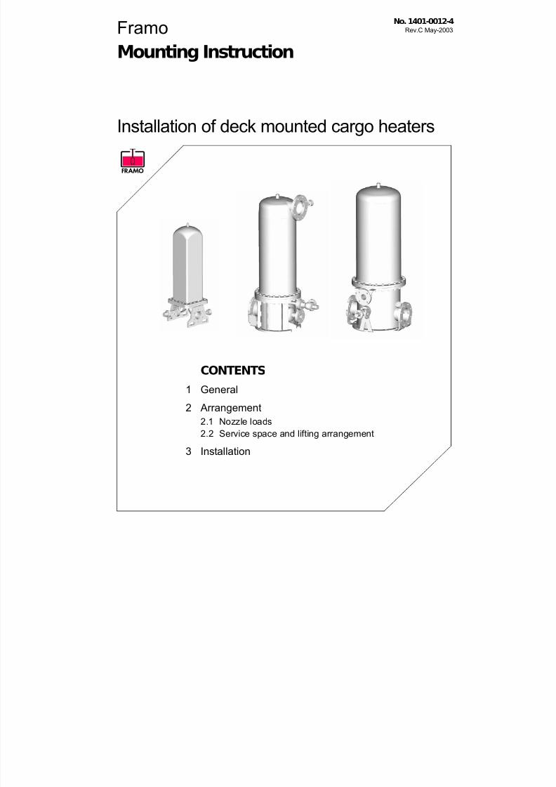
7/16/2019 Pompe Framo
http://slidepdf.com/reader/full/pompe-framo 95/175
Framo
Mounting Instruction
Installation of deck mounted cargo heaters
No. 1401-0012-4Rev.C May-2003
CONTENTS
1 General
2 Arrangement
2.1 Nozzle loads
2.2 Service space and lifting arrangement
3 Installation
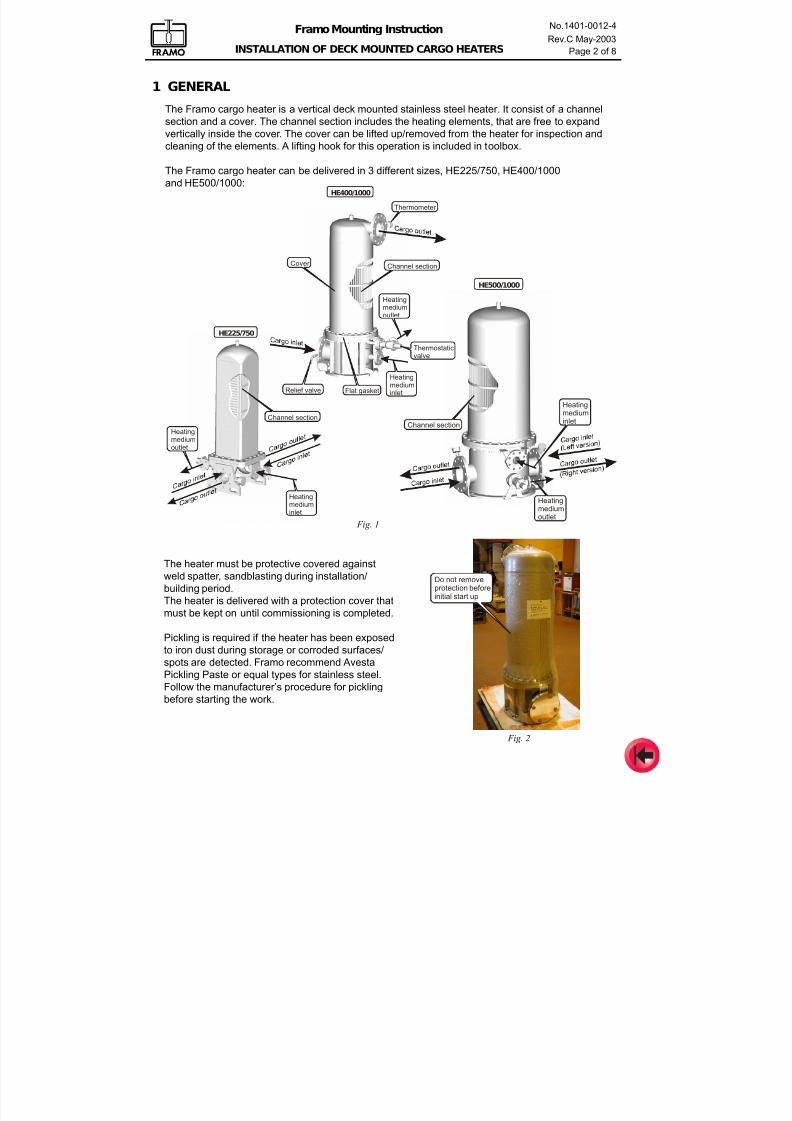
7/16/2019 Pompe Framo
http://slidepdf.com/reader/full/pompe-framo 96/175
Framo Mounting Instruction
INSTALLATION OF DECK MOUNTED CARGO HEATERS
No.1401-0012-4
Rev.C May-2003
Page 2 of 8
Fig. 1
1 GENERAL
The Framo cargo heater is a vertical deck mounted stainless steel heater. It consist of a channel
section and a cover. The channel section includes the heating elements, that are free to expand
vertically inside the cover. The cover can be lifted up/removed from the heater for inspection andcleaning of the elements. A lifting hook for this operation is included in toolbox.
The Framo cargo heater can be delivered in 3 different sizes, HE225/750, HE400/1000
and HE500/1000:
Thermometer
Relief valve
HeatingmediuminletFlat gasket
Cover
Heatingmediumoutlet
Thermostaticvalve
HE400/1000
Channel section
Heating
mediuminlet
Heatingmediumoutlet
HE500/1000
Channel section
HE225/750
Channel section
Heatingmediuminlet
Heatingmediumoutlet
The heater must be protective covered against
weld spatter, sandblasting during installation/
building period.
The heater is delivered with a protection cover that
must be kept on until commissioning is completed.
Pickling is required if the heater has been exposed
to iron dust during storage or corroded surfaces/
spots are detected. Framo recommend Avesta
Pickling Paste or equal types for stainless steel.
Follow the manufacturer’s procedure for pickling
before starting the work.
Do not removeprotection beforeinitial start up
Fig. 2
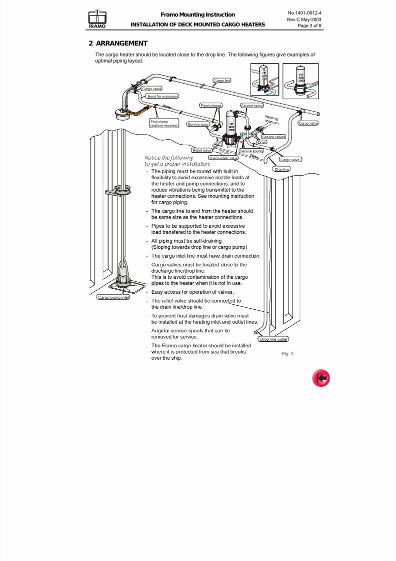
7/16/2019 Pompe Framo
http://slidepdf.com/reader/full/pompe-framo 97/175
Framo Mounting Instruction
INSTALLATION OF DECK MOUNTED CARGO HEATERS
No.1401-0012-4
Rev.C May-2003
Page 3 of 8
Cargo pump inlet
Cargo line
Drop line
Drop line outlet
Thermostatic valve
Service spoolFirst clampresilient mounted
HE
400/
1000
Cargo valve
Cargo valve
Cargo valve
Service valvesDrain
Service spools
HE
500/
1000
Service spoolFixed clamps
Bend for expansion
HE
225/
750
Relief valve
2 ARRANGEMENT
The cargo heater should be located close to the drop line. The following figures give examples of
optimal piping layout.
Fig. 3
Not ice the fo l lowing
to get a proper instal lat ion:
- The piping must be routed with built in
flexibility to avoid excessive nozzle loads at
the heater and pump connections, and to
reduce vibrations being transmittet to the
heater connections. See mounting instruction
for cargo piping.
- The cargo line to and from the heater should
be same size as the heater connections.
- Pipes to be supported to avoid excessive
load transfered to the heater connections.
- All piping must be self-draining.
(Sloping towards drop line or cargo pump)
- The cargo inlet line must have drain connection.
- Cargo valves must be located close to the
discharge line/drop line.
This is to avoid contamination of the cargopipes to the heater when it is not in use.
- Easy access for operation of valves.
- The relief valve should be connected to
the drain line/drop line.
- To prevent frost damages drain valve must
be installed at the heating inlet and outlet lines.
- Angular service spools that can be
removed for service.
- The Framo cargo heater should be installedwhere it is protected from sea that breaks
over the ship.
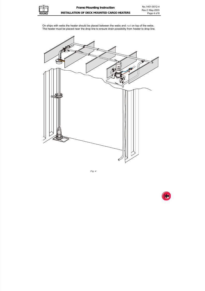
7/16/2019 Pompe Framo
http://slidepdf.com/reader/full/pompe-framo 98/175
Framo Mounting Instruction
INSTALLATION OF DECK MOUNTED CARGO HEATERS
No.1401-0012-4
Rev.C May-2003
Page 4 of 8
HE400/1000
HE
500/
1000
Fig. 4
On ships with webs the heater should be placed between the webs and not on top of the webs.
The heater must be placed near the drop line to ensure drain possibility from heater to drop line.
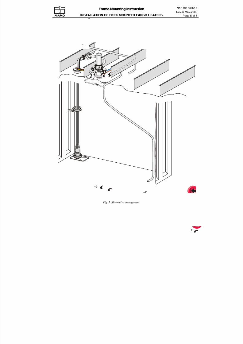
7/16/2019 Pompe Framo
http://slidepdf.com/reader/full/pompe-framo 99/175
Framo Mounting Instruction
INSTALLATION OF DECK MOUNTED CARGO HEATERS
No.1401-0012-4
Rev.C May-2003
Page 5 of 8
HE400/1000
HE
500/
1000
Fig. 5 Alternative arrangement
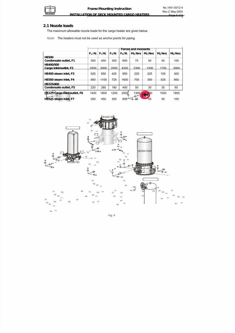
7/16/2019 Pompe Framo
http://slidepdf.com/reader/full/pompe-framo 100/175
Framo Mounting Instruction
INSTALLATION OF DECK MOUNTED CARGO HEATERS
No.1401-0012-4
Rev.C May-2003
Page 6 of 8
2.1 Nozzle loads
The maximum allowable nozzle loads for the cargo heater are given below.
Note! The heaters must not be used as anchor points for piping.
Fig. 6
FZ
MZ
FYMY
FXMX
FYMY
FZ
MZMX FX
FZ
MZFY
MY
FXMX
FY
FZ
FX
MX
MZ
MYFZ
MZ
FYMY
FXMX
F4
F1
F2 F2
F2
F1
F3
F2
FY
FY
FY
FZ
FZ
FZ
FX
FX
FX
MX
MX
MX
MZ
MZ
MZ
MY
MY
MY
FY
FZ
FX
MX
MZ
MY
HE400/1000
HE500/1000
F7F6
F5F6
FZ
MZ
FXMX
FYMY
FZ
MZ
FXMX
FY
MY
FZ
MZ
FXMX
FY
MY
HE250/750
Forces and moments
FX[N] F Y [N] FZ[N] FR[N] MX[Nm] M Y [Nm] Mz[Nm] MR[Nm]
HE500Condensate outlet, F1 350 450 300 650 75 50 50 100
HE400/500Cargo inlet/outlet, F2 2500 3000 2000 4350 2300 1200 1750 3000
HE400 steam inlet, F3 525 650 425 950 225 225 100 300
HE500 steam inlet, F4 900 1100 725 1600 700 350 525 950
HE225/400Condensate outlet, F5 220 280 180 400 50 30 35 65
HE225 Cargo inlet/outlet, F6 1400 1800 1200 2500 1300 700 1000 1800
HE225 steam inlet, F7 350 450 300 650 75 50 50 100
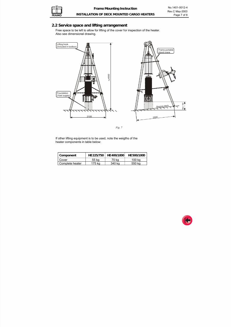
7/16/2019 Pompe Framo
http://slidepdf.com/reader/full/pompe-framo 101/175
Framo Mounting Instruction
INSTALLATION OF DECK MOUNTED CARGO HEATERS
No.1401-0012-4
Rev.C May-2003
Page 7 of 8
2.2 Service space and lifting arrangement
Free space to be left to allow for lifting of the cover for inspection of the heater.
Also see dimensional drawing.
2100 2500
Max.500
4000
S lop ing dec k
Framo portabletripod crane
Foundation(Yard supply)
Lifting hook(included in toolbox)
Fig. 7
If other lifting equipment is to be used, note the weigths of the
heater components in table below:
Component HE225/750 HE400/1000 HE500/1000
Cover 55 kg 70 kg 100 kg
Complete heater 175 kg 340 kg 550 kg
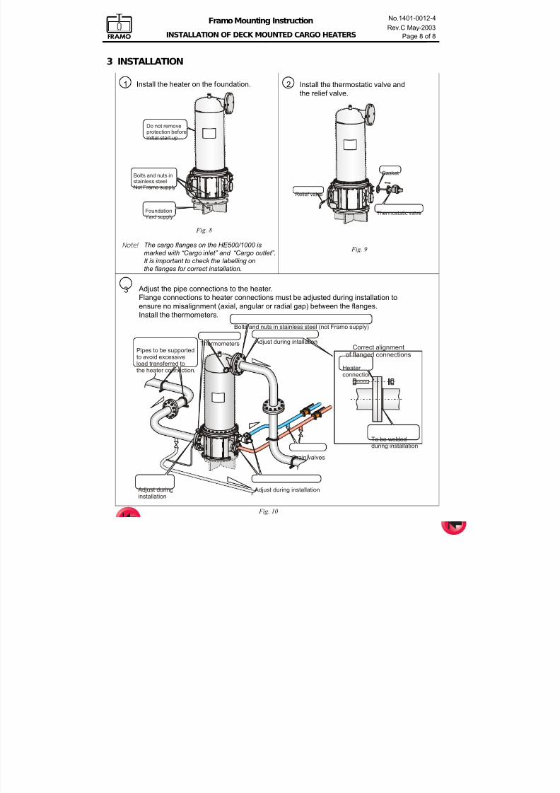
7/16/2019 Pompe Framo
http://slidepdf.com/reader/full/pompe-framo 102/175
Framo Mounting Instruction
INSTALLATION OF DECK MOUNTED CARGO HEATERS
No.1401-0012-4
Rev.C May-2003
Page 8 of 8
FoundationYard supply
Do not removeprotection beforeinitial start up
Bolts and nuts instainless steelNot Framo supply
Thermostatic valve
Relief valve
Gasket
Pipes to be supportedto avoid excessiveload transferred tothe heater connection.
Adjust during installation
Adjust during intallation
Bolts and nuts in stainless steel (not Framo supply)
Drain valves
Correct alignmentof flanged connections
Heater connection
To be weldedduring installation
Adjust duringinstallation
Thermometers
1 Install the heater on the foundation. 2 Install the thermostatic valve and
the relief valve.
3
Fig. 9
Fig. 8
Fig. 10
3 INSTALLATION
Adjust the pipe connections to the heater.
Flange connections to heater connections must be adjusted during installation to
ensure no misalignment (axial, angular or radial gap) between the flanges.
Install the thermometers.
Note! The cargo flanges on the HE500/1000 is
marked with “Cargo inlet” and “Cargo outlet”.
It is important to check the labelling on
the flanges for correct installation.
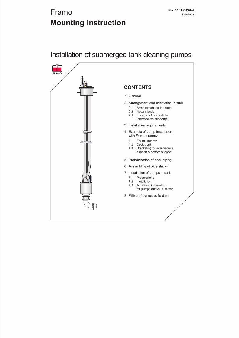
7/16/2019 Pompe Framo
http://slidepdf.com/reader/full/pompe-framo 103/175
Framo
Mounting Instruction
Installation of submerged tank cleaning pumps
No. 1401-0026-4
Feb-2003
CONTENTS
1 General
2 Arrangement and orientation in tank
2.1 Arrangement on top plate
2.2 Nozzle loads
2.3 Location of brackets for
intermediate support(s)
3 Installation requirements
4 Example of pump installation
with Framo dummy
4.1 Framo dummy
4.2 Deck trunk
4.3 Bracket(s) for intermediate
support & bottom support
5 Prefabrication of deck piping
6 Assembling of pipe stacks
7 Installation of pumps in tank
7.1 Preparations
7.2 Installation
7.3 Additional information
for pumps above 20 meter
8 Filling of pumps cofferdam
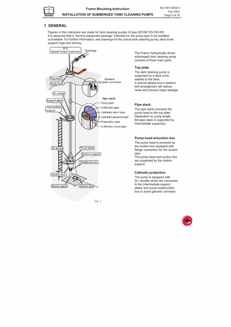
7/16/2019 Pompe Framo
http://slidepdf.com/reader/full/pompe-framo 104/175
Framo Mounting Instruction
INSTALLATION OF SUBMERGED TANK CLEANING PUMPS
No.1401-0026-4
Feb-2003
Page 2 of 19
1 GENERAL
Figures in this instruction are made for tank cleaning pumps of type SD100/125/150-W5.
It is assumed that a “dummy equipment package” intended for the pump type to be installed,
is available. For further information, see drawings for the actual tank cleaning pump, deck trunk,support rings and dummy.
Fig. 1
The Framo hydraulically driven
submerged tank cleaning pump
consists of three main parts:
Top plate
The tank cleaning pump is
supported by a deck trunk
welded to the deck. A special gasket and a resilient
bolt arrangement will reduce
noise and prevent cargo leakage.
Pipe stack
The pipe stack connects the
pump head to the top plate.
Dependent on pump length,
the pipe stack is supported byintermediate support(s).
Pump head w/suction box
The pump head is enclosed by
the suction box equipped with
flange connection for the suction
pipe.
The pump head and suction box
are supported by the bottomsupport.
Cathodic protection
The pump is equipped with
Zn- anodes which are connected
to the intermediate support
plates and pump head/suction
box to avoid galvanic corrosion.
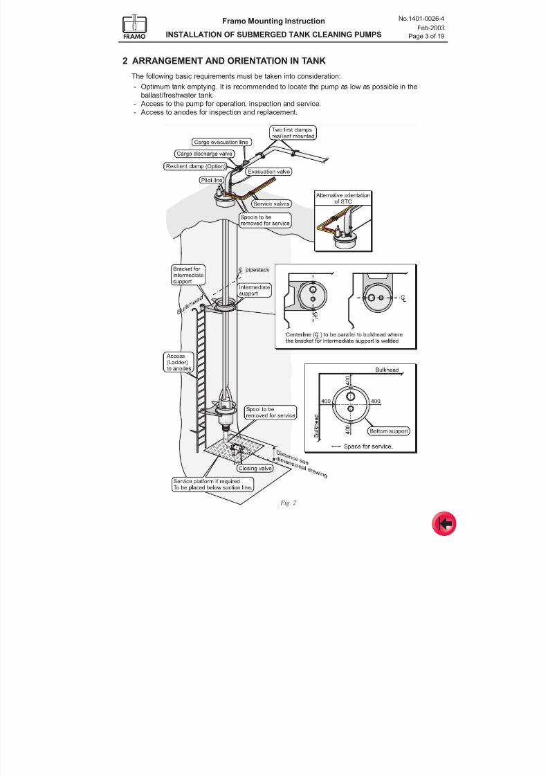
7/16/2019 Pompe Framo
http://slidepdf.com/reader/full/pompe-framo 105/175
Framo Mounting Instruction
INSTALLATION OF SUBMERGED TANK CLEANING PUMPS
No.1401-0026-4
Feb-2003
Page 3 of 19
Fig. 2
2 ARRANGEMENT AND ORIENTATION IN TANK
The following basic requirements must be taken into consideration:
- Optimum tank emptying. It is recommended to locate the pump as low as possible in the
ballast/freshwater tank.- Access to the pump for operation, inspection and service.
- Access to anodes for inspection and replacement.
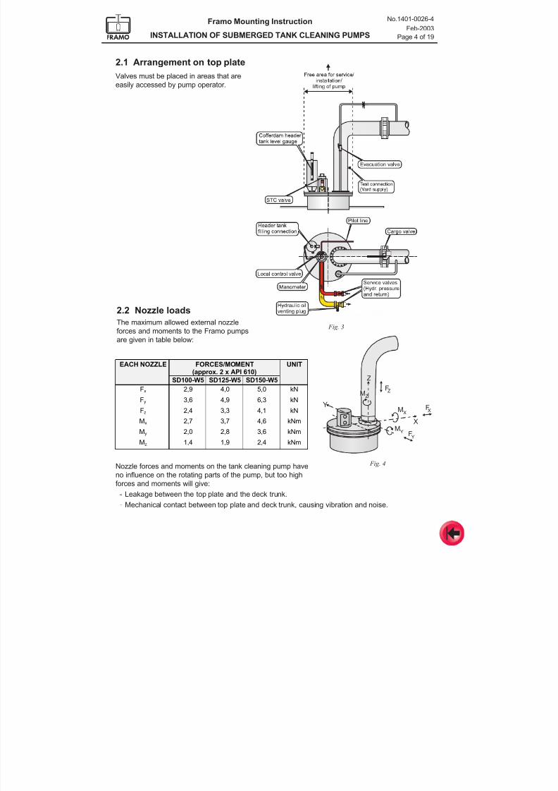
7/16/2019 Pompe Framo
http://slidepdf.com/reader/full/pompe-framo 106/175
Framo Mounting Instruction
INSTALLATION OF SUBMERGED TANK CLEANING PUMPS
No.1401-0026-4
Feb-2003
Page 4 of 19
2.1 Arrangement on top plate
Valves must be placed in areas that are
easily accessed by pump operator.
Fig. 3
2.2 Nozzle loads
The maximum allowed external nozzle
forces and moments to the Framo pumps
are given in table below:
Nozzle forces and moments on the tank cleaning pump have
no influence on the rotating parts of the pump, but too high
forces and moments will give:
- Leakage between the top plate and the deck trunk.
- Mechanical contact between top plate and deck trunk, causing vibration and noise.
Fig. 4
Z
M F
MF
M F
ZZ
YY
X XY
X
EACH NOZZLE FORCES/MOMENT
(approx. 2 x API 610)UNIT
SD100-W5 SD125-W5 SD150-W5
Fx 2,9 4,0 5,0 kNFy 3,6 4,9 6,3 kN
Fz 2,4 3,3 4,1 kN
Mx 2,7 3,7 4,6 kNm
My 2,0 2,8 3,6 kNm
Mz 1,4 1,9 2,4 kNm
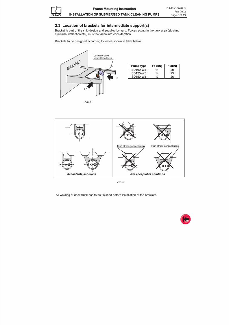
7/16/2019 Pompe Framo
http://slidepdf.com/reader/full/pompe-framo 107/175
Framo Mounting Instruction
INSTALLATION OF SUBMERGED TANK CLEANING PUMPS
No.1401-0026-4
Feb-2003
Page 5 of 19
2.3 Location of brackets for intermediate support(s)
Bracket is part of the ship design and supplied by yard. Forces acting in the tank area (sloshing,
structural deflection etc.) must be taken into consideration.
Brackets to be designed according to forces shown in table below:
Fig. 5
Fig. 6
All welding of deck trunk has to be finished before installation of the brackets.
Pump type F1 (kN) F2(kN)
SD100-W5 11 20SD125-W5 14 23SD150-W5 17 26
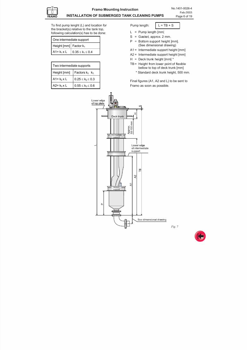
7/16/2019 Pompe Framo
http://slidepdf.com/reader/full/pompe-framo 108/175
Framo Mounting Instruction
INSTALLATION OF SUBMERGED TANK CLEANING PUMPS
No.1401-0026-4
Feb-2003
Page 6 of 19
One intermediate support
Height [mm] Factor k1
A1= k1 x L 0.35 ≤ k1≤ 0.4
Two intermediate supports
Height [mm] Factors k2 k3
A1= k2 x L 0.25 ≤ k2≤ 0.3
A2= k3 x L 0.55 ≤ k3≤ 0.6
To find pump lenght (L) and location for
the bracket(s) relative to the tank top,
following calculation(s) has to be done: L = Pump length [mm]
S = Gasket, approx. 2 mm.
P = Bottom support height [mm].
(See dimensional drawing)
A1 = Intermediate support height [mm]
A2 = Intermediate support height [mm]
H = Deck trunk height [mm] *
TB = Height from lower point of flexible
bellow to top of deck trunk [mm]
* Standard deck trunk height, 500 mm.
Final figures (A1, A2 and L) to be sent to
Framo as soon as possible.
Fig. 7
Pump length: L = TB + S
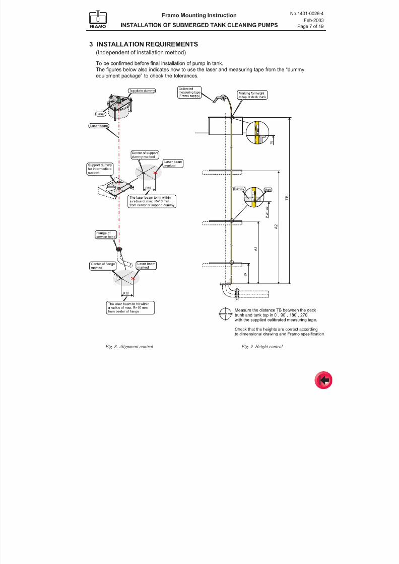
7/16/2019 Pompe Framo
http://slidepdf.com/reader/full/pompe-framo 109/175
Framo Mounting Instruction
INSTALLATION OF SUBMERGED TANK CLEANING PUMPS
No.1401-0026-4
Feb-2003
Page 7 of 19
3 INSTALLATION REQUIREMENTS
(Independent of installation method)
To be confirmed before final installation of pump in tank.
The figures below also indicates how to use the laser and measuring tape from the “dummyequipment package” to check the tolerances.
Fig. 8 Alignment control Fig. 9 Height control
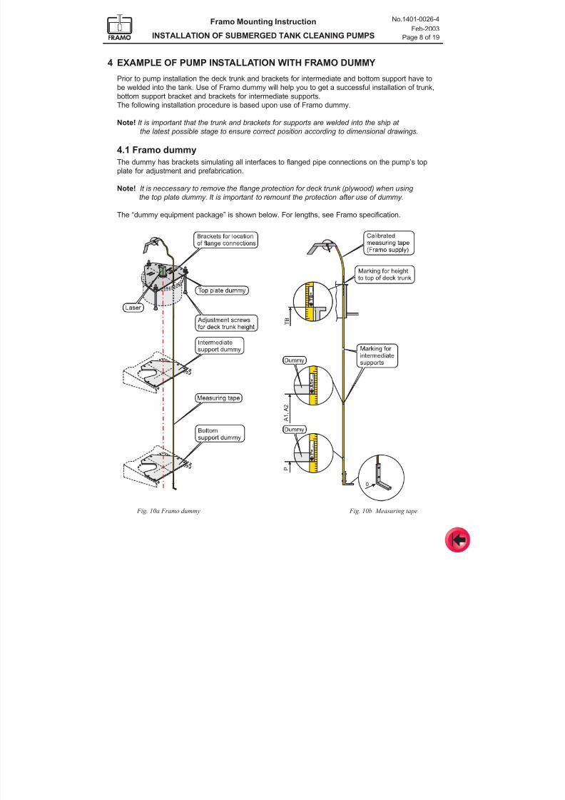
7/16/2019 Pompe Framo
http://slidepdf.com/reader/full/pompe-framo 110/175
Framo Mounting Instruction
INSTALLATION OF SUBMERGED TANK CLEANING PUMPS
No.1401-0026-4
Feb-2003
Page 8 of 19
Fig. 10a Framo dummy
4 EXAMPLE OF PUMP INSTALLATION WITH FRAMO DUMMY
Prior to pump installation the deck trunk and brackets for intermediate and bottom support have to
be welded into the tank. Use of Framo dummy will help you to get a successful installation of trunk,
bottom support bracket and brackets for intermediate supports.The following installation procedure is based upon use of Framo dummy.
Note! It is important that the trunk and brackets for supports are welded into the ship at
the latest possible stage to ensure correct position according to dimensional drawings.
4.1 Framo dummy
The dummy has brackets simulating all interfaces to flanged pipe connections on the pump’s top
plate for adjustment and prefabrication.
Note! It is neccessary to remove the flange protection for deck trunk (plywood) when using
the top plate dummy. It is important to remount the protection after use of dummy.
The “dummy equipment package” is shown below. For lengths, see Framo specification.
Fig. 10b Measuring tape
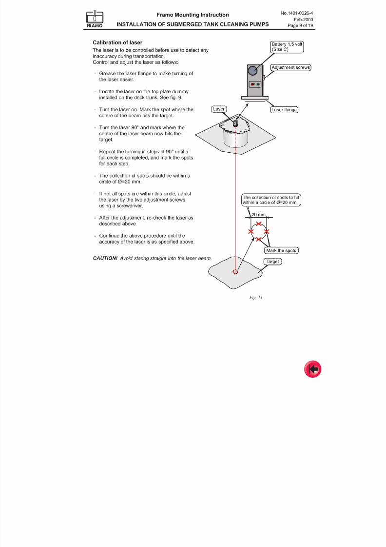
7/16/2019 Pompe Framo
http://slidepdf.com/reader/full/pompe-framo 111/175
Framo Mounting Instruction
INSTALLATION OF SUBMERGED TANK CLEANING PUMPS
No.1401-0026-4
Feb-2003
Page 9 of 19
Calibration of laser
The laser is to be controlled before use to detect any
inaccuracy during transportation.
Control and adjust the laser as follows:
Fig. 11
- Grease the laser flange to make turning of
the laser easier.
- Locate the laser on the top plate dummy
installed on the deck trunk. See fig. 9.
- Turn the laser on. Mark the spot where the
centre of the beam hits the target.
- Turn the laser 90° and mark where the
centre of the laser beam now hits thetarget.
- Repeat the turning in steps of 90° until a
full circle is completed, and mark the spots
for each step.
- The collection of spots should be within a
circle of Ø=20 mm.
- If not all spots are within this circle, adjust
the laser by the two adjustment screws,
using a screwdriver.
- After the adjustment, re-check the laser as
described above.
- Continue the above procedure until the
accuracy of the laser is as specified above.
CAUTION! Avoid staring straight into the laser beam.
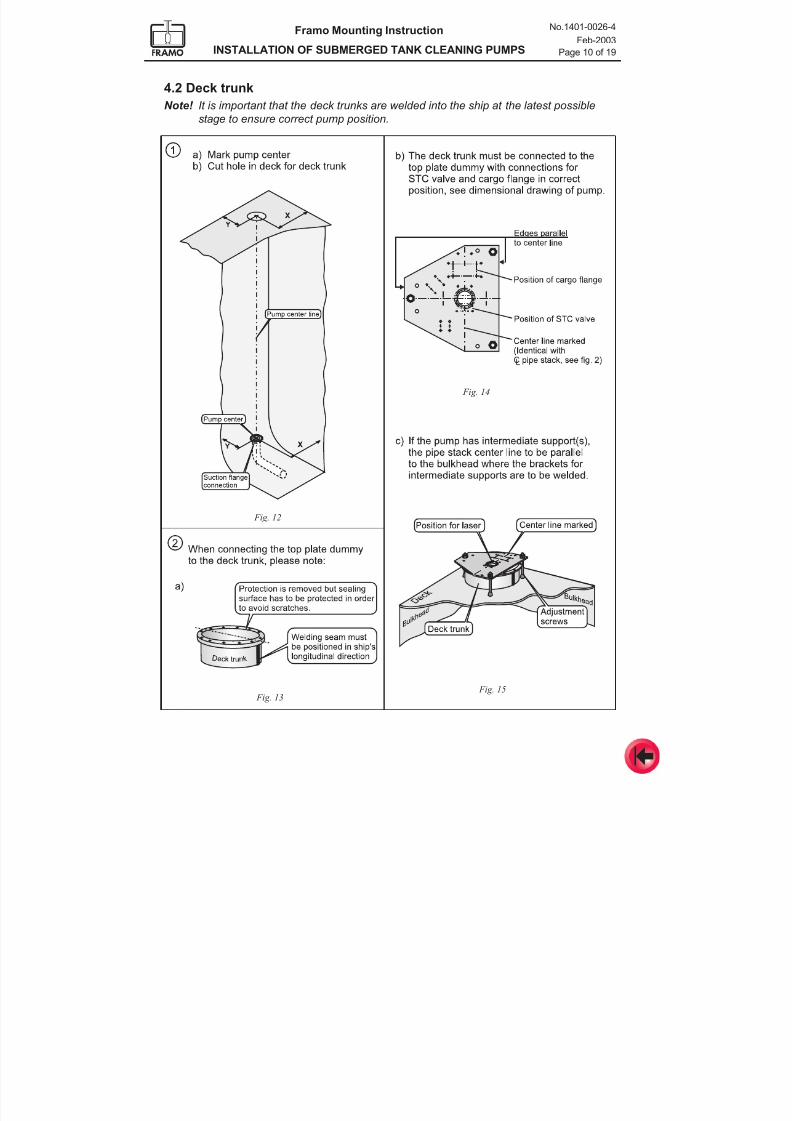
7/16/2019 Pompe Framo
http://slidepdf.com/reader/full/pompe-framo 112/175
Framo Mounting Instruction
INSTALLATION OF SUBMERGED TANK CLEANING PUMPS
No.1401-0026-4
Feb-2003
Page 10 of 19
4.2 Deck trunk
Note! It is important that the deck trunks are welded into the ship at the latest possible
stage to ensure correct pump position.
Fig. 15
Fig. 14
Fig. 12
Fig. 13
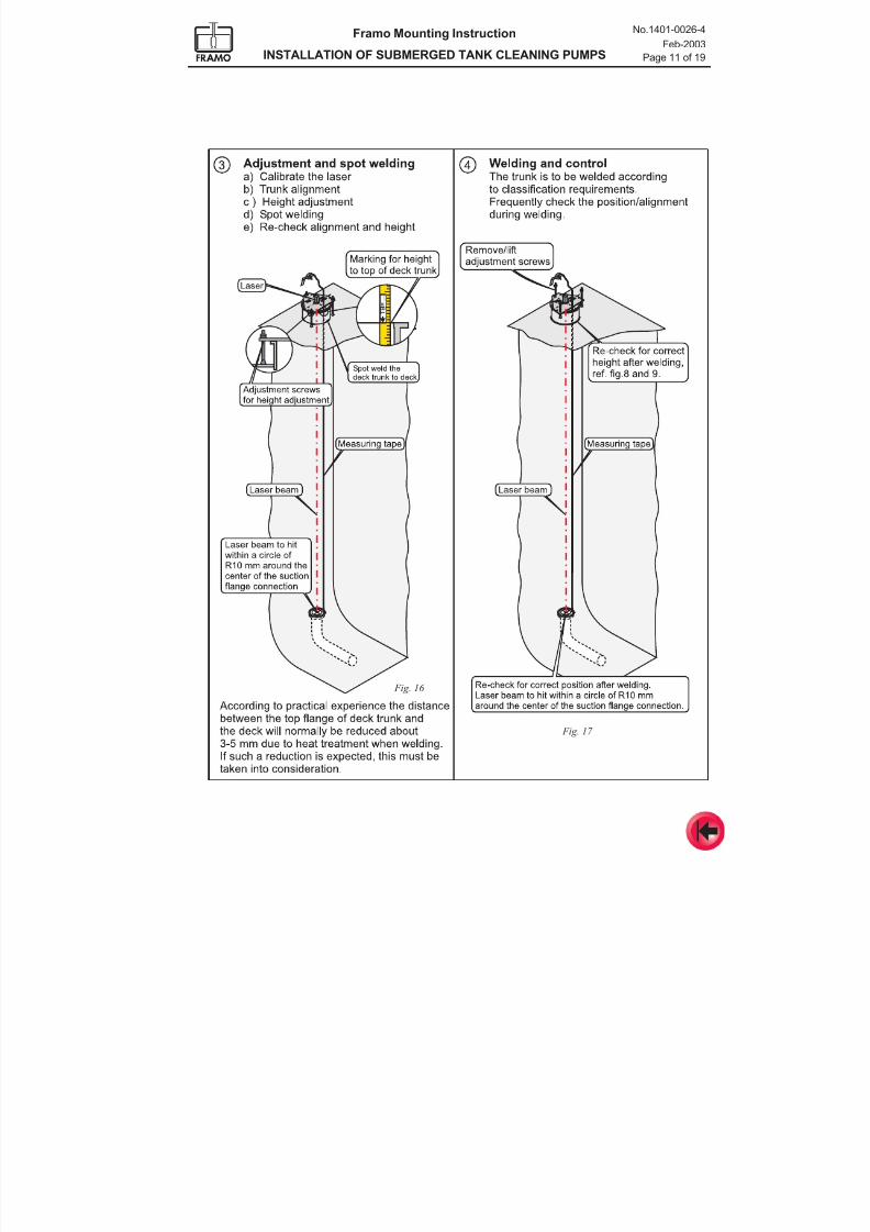
7/16/2019 Pompe Framo
http://slidepdf.com/reader/full/pompe-framo 113/175
Framo Mounting Instruction
INSTALLATION OF SUBMERGED TANK CLEANING PUMPS
No.1401-0026-4
Feb-2003
Page 11 of 19
Fig. 16
Fig. 17
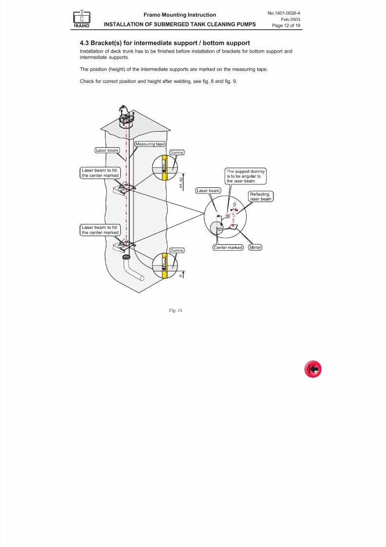
7/16/2019 Pompe Framo
http://slidepdf.com/reader/full/pompe-framo 114/175
Framo Mounting Instruction
INSTALLATION OF SUBMERGED TANK CLEANING PUMPS
No.1401-0026-4
Feb-2003
Page 12 of 19
4.3 Bracket(s) for intermediate support / bottom support
Installation of deck trunk has to be finished before installation of brackets for bottom support and
intermediate supports.
The position (height) of the intermediate supports are marked on the measuring tape.
Check for correct position and height after welding, see fig. 8 and fig. 9.
Fig. 18
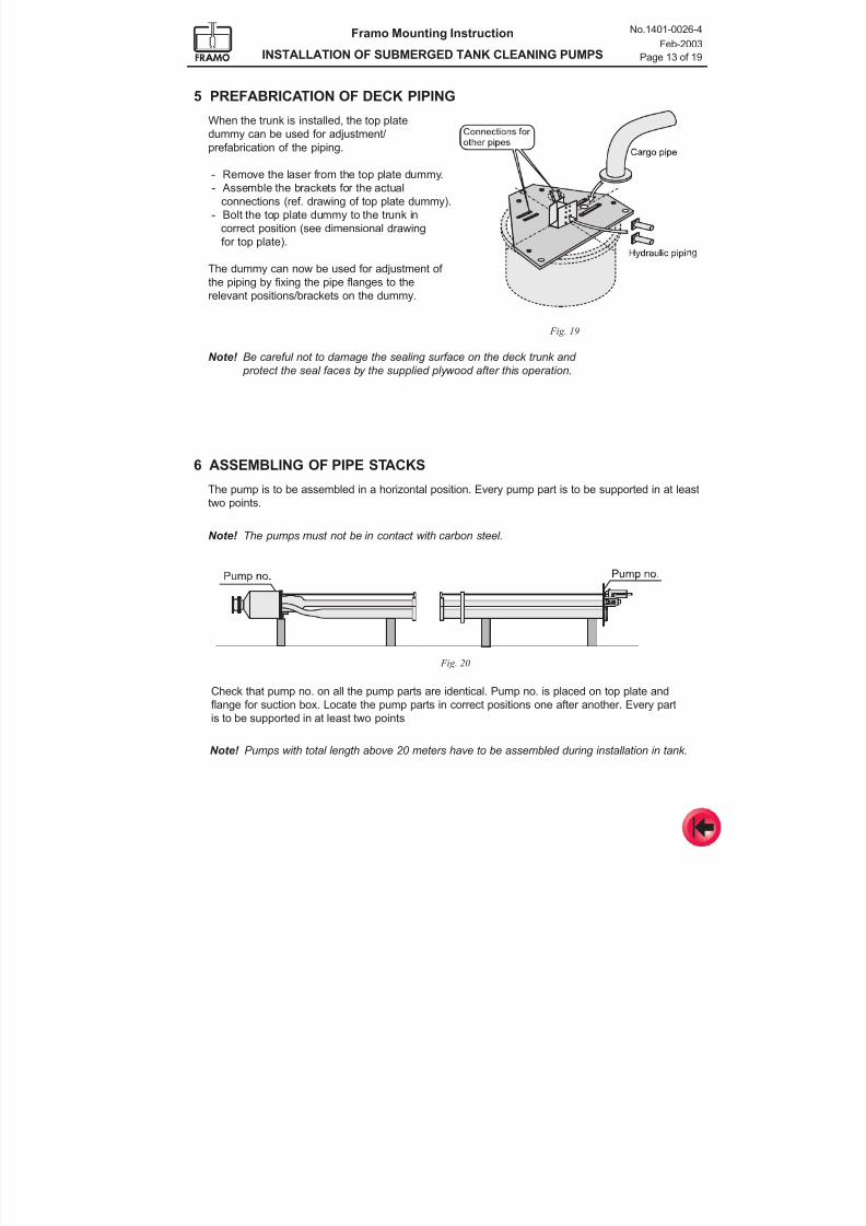
7/16/2019 Pompe Framo
http://slidepdf.com/reader/full/pompe-framo 115/175
Framo Mounting Instruction
INSTALLATION OF SUBMERGED TANK CLEANING PUMPS
No.1401-0026-4
Feb-2003
Page 13 of 19
5 PREFABRICATION OF DECK PIPING
When the trunk is installed, the top plate
dummy can be used for adjustment/
prefabrication of the piping.
- Remove the laser from the top plate dummy.
- Assemble the brackets for the actual
connections (ref. drawing of top plate dummy).
- Bolt the top plate dummy to the trunk in
correct position (see dimensional drawing
for top plate).
The dummy can now be used for adjustment of
the piping by fixing the pipe flanges to the
relevant positions/brackets on the dummy.
6 ASSEMBLING OF PIPE STACKS
The pump is to be assembled in a horizontal position. Every pump part is to be supported in at least
two points.
Note! The pumps must not be in contact with carbon steel.
Fig. 20
Fig. 19
Check that pump no. on all the pump parts are identical. Pump no. is placed on top plate and
flange for suction box. Locate the pump parts in correct positions one after another. Every part
is to be supported in at least two points
Note! Be careful not to damage the sealing surface on the deck trunk and
protect the seal faces by the supplied plywood after this operation.
Note! Pumps with total length above 20 meters have to be assembled during installation in tank.
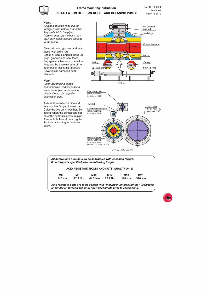
7/16/2019 Pompe Framo
http://slidepdf.com/reader/full/pompe-framo 116/175
Framo Mounting Instruction
INSTALLATION OF SUBMERGED TANK CLEANING PUMPS
No.1401-0026-4
Feb-2003
Page 14 of 19
All screws and nuts have to be assembled with specified torque.
If no torque is specified, use the following torque:
ACID RESISTANT BOLTS AND NUTS, QUALITY A4-80
M6 M8 M10 M12 M16 M20
9.2 Nm 22.3 Nm 44.2 Nm 76.2 Nm 190 Nm 370 Nm
Acid resistant bolts are to be coated with “Molybdenum disculphide” (Molycote)
or similar on threads and under bolt heads/nuts prior to assembling.
Note !
All pipes must be checked for
foreign bodies before connection.
Any parts left in the pipes
(screws, nuts, plastic bolts rags,etc.) may cause serious damage
to the pump.
Clean all o-ring grooves and seal
faces with a dry rag.
Check all seal elements, back-up
rings, grooves and seal faces.
Pay special attention to the teflon
rings and be absolute sure of no
deformation nor radial grooves.
Never install damaged seal
elements.
Note!
When assembling flange
connections in vertical position,
lower the upper pump section
slowly. Do not damage the
connection pipe.
Assemble connection pipe and
seals on the flange of lower part.
Guide the two parts together. Becareful when the connection pipe
enter the hydraulic pressure pipe.
Assemble bolts and nuts. Tighten
the bolts according to the table
below.
Fig. 21
Fig. 22 Split flanges
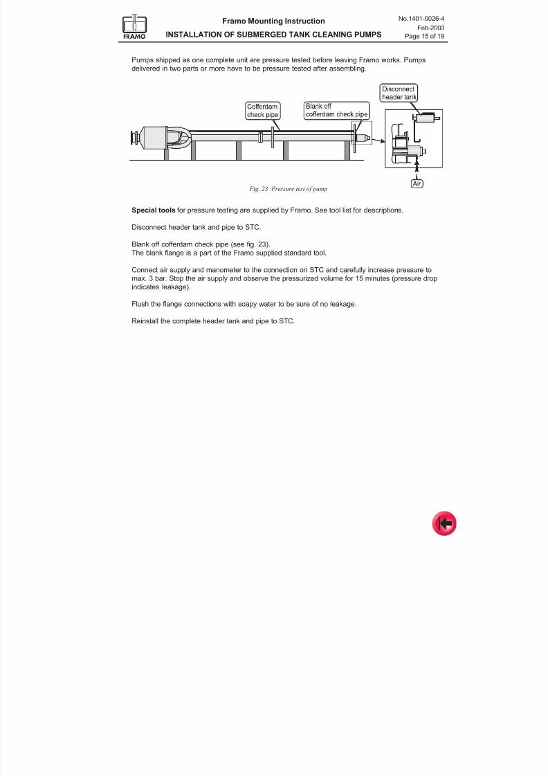
7/16/2019 Pompe Framo
http://slidepdf.com/reader/full/pompe-framo 117/175
Framo Mounting Instruction
INSTALLATION OF SUBMERGED TANK CLEANING PUMPS
No.1401-0026-4
Feb-2003
Page 15 of 19
Pumps shipped as one complete unit are pressure tested before leaving Framo works. Pumps
delivered in two parts or more have to be pressure tested after assembling.
Fig. 23 Pressure test of pump
Special tools for pressure testing are supplied by Framo. See tool list for descriptions.
Disconnect header tank and pipe to STC.
Blank off cofferdam check pipe (see fig. 23).
The blank flange is a part of the Framo supplied standard tool.
Connect air supply and manometer to the connection on STC and carefully increase pressure to
max. 3 bar. Stop the air supply and observe the pressurized volume for 15 minutes (pressure drop
indicates leakage).
Flush the flange connections with soapy water to be sure of no leakage.
Reinstall the complete header tank and pipe to STC.
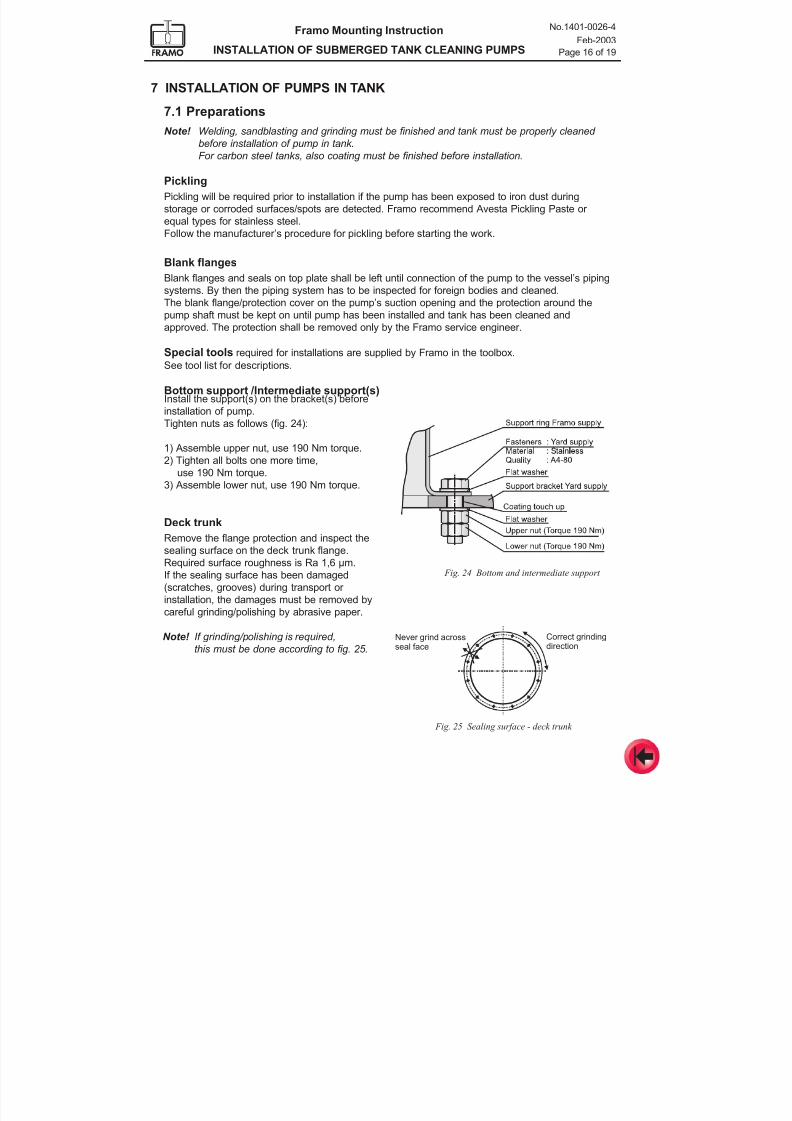
7/16/2019 Pompe Framo
http://slidepdf.com/reader/full/pompe-framo 118/175
Framo Mounting Instruction
INSTALLATION OF SUBMERGED TANK CLEANING PUMPS
No.1401-0026-4
Feb-2003
Page 16 of 19
Fig. 25 Sealing surface - deck trunk
Fig. 24 Bottom and intermediate support
Correct grindingdirection
Never grind acrossseal face
7 INSTALLATION OF PUMPS IN TANK
7.1 Preparations
Note! Welding, sandblasting and grinding must be finished and tank must be properly cleaned
before installation of pump in tank.
For carbon steel tanks, also coating must be finished before installation.
Pickling
Pickling will be required prior to installation if the pump has been exposed to iron dust during
storage or corroded surfaces/spots are detected. Framo recommend Avesta Pickling Paste or
equal types for stainless steel.
Follow the manufacturer’s procedure for pickling before starting the work.
Blank flanges
Blank flanges and seals on top plate shall be left until connection of the pump to the vessel’s pipingsystems. By then the piping system has to be inspected for foreign bodies and cleaned.
The blank flange/protection cover on the pump’s suction opening and the protection around the
pump shaft must be kept on until pump has been installed and tank has been cleaned and
approved. The protection shall be removed only by the Framo service engineer.
Special tools required for installations are supplied by Framo in the toolbox.
See tool list for descriptions.
Bottom support /Intermediate support(s)Install the support(s) on the bracket(s) before
installation of pump.Tighten nuts as follows (fig. 24):
1) Assemble upper nut, use 190 Nm torque.
2) Tighten all bolts one more time,
use 190 Nm torque.
3) Assemble lower nut, use 190 Nm torque.
Deck trunk
Remove the flange protection and inspect the
sealing surface on the deck trunk flange.Required surface roughness is Ra 1,6 µm.
If the sealing surface has been damaged
(scratches, grooves) during transport or
installation, the damages must be removed by
careful grinding/polishing by abrasive paper.
Note! If grinding/polishing is required,
this must be done according to fig. 25.
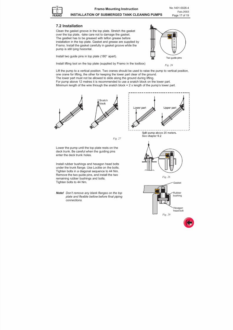
7/16/2019 Pompe Framo
http://slidepdf.com/reader/full/pompe-framo 119/175
Framo Mounting Instruction
INSTALLATION OF SUBMERGED TANK CLEANING PUMPS
No.1401-0026-4
Feb-2003
Page 17 of 19
7.2 Installation
Clean the gasket groove in the top plate. Stretch the gasket
over the top plate, -take care not to damage the gasket.
The gastket has to be greased with teflon grease before
installation in the top plate. Gasket and grease are supplied byFramo. Install the gasket carefully in gasket groove while the
pump is still lying hoizontal.
Install two guide pins in top plate (180° apart).
Install lifting tool on the top plate (supplied by Framo in the toolbox)
Lift the pump to a vertical position. Two cranes should be used to raise the pump to vertical position,
one crane for lifting, the other for keeping the lower part clear of the ground.
The lower part must not be allowed to slide along the ground during lifting.
For pump above 12 metres it is recommended to use a snatch block on the lower part.Minimum length of the wire through the snatch block = 2 x length of the pump’s lower part.
Lower the pump until the top plate rests on the
deck trunk. Be careful when the guiding pins
enter the deck trunk holes.
Install rubber bushings and hexagon head boltsunder the trunk flange. Use Loctite on the bolts.
Tighten bolts in a diagonal sequence to 44 Nm.
Remove the two guide pins, and install the two
remaining rubber bushings and bolts.
Tighten bolts to 44 Nm.
Note! Don’t remove any blank flanges on the top
plate and flexible bellow before final piping
connections.
Fig. 26
Fig. 28
Fig. 29
Fig. 27
Rubber bushing
Hexagonhead bolt
Gasket
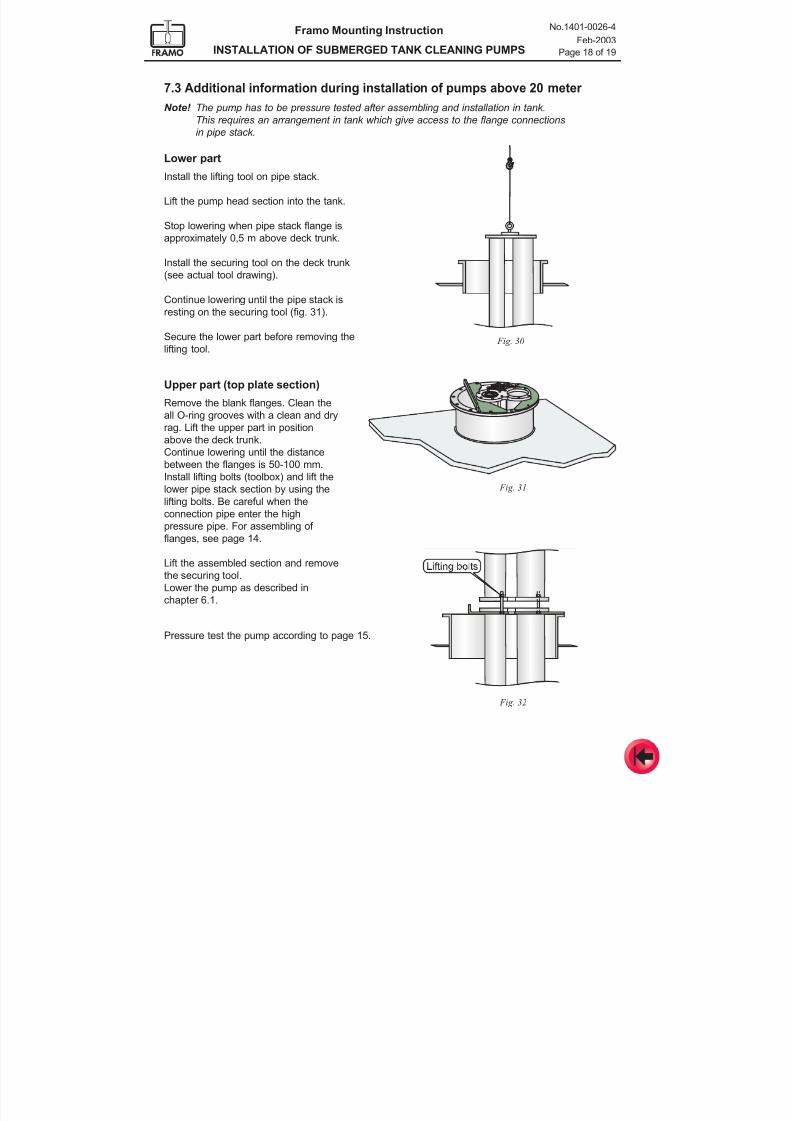
7/16/2019 Pompe Framo
http://slidepdf.com/reader/full/pompe-framo 120/175
Framo Mounting Instruction
INSTALLATION OF SUBMERGED TANK CLEANING PUMPS
No.1401-0026-4
Feb-2003
Page 18 of 19
Fig. 30
Fig. 31
7.3 Additional information during installation of pumps above 20 meter
Note! The pump has to be pressure tested after assembling and installation in tank.
This requires an arrangement in tank which give access to the flange connections
in pipe stack.
Lower part
Install the lifting tool on pipe stack.
Lift the pump head section into the tank.
Stop lowering when pipe stack flange is
approximately 0,5 m above deck trunk.
Install the securing tool on the deck trunk
(see actual tool drawing).
Continue lowering until the pipe stack is
resting on the securing tool (fig. 31).
Secure the lower part before removing the
lifting tool.
Upper part (top plate section)
Remove the blank flanges. Clean the
all O-ring grooves with a clean and dryrag. Lift the upper part in position
above the deck trunk.
Continue lowering until the distance
between the flanges is 50-100 mm.
Install lifting bolts (toolbox) and lift the
lower pipe stack section by using the
lifting bolts. Be careful when the
connection pipe enter the high
pressure pipe. For assembling of
flanges, see page 14.
Lift the assembled section and remove
the securing tool.
Lower the pump as described in
chapter 6.1.
Pressure test the pump according to page 15.
Fig. 32
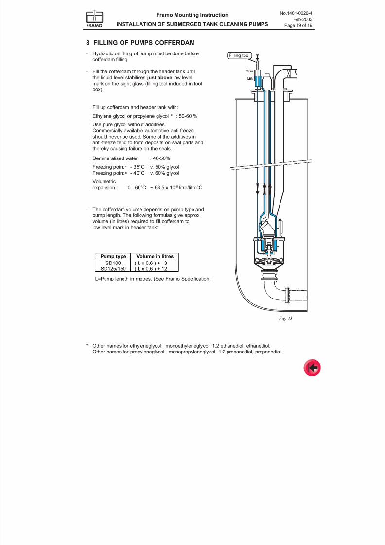
7/16/2019 Pompe Framo
http://slidepdf.com/reader/full/pompe-framo 121/175
Framo Mounting Instruction
INSTALLATION OF SUBMERGED TANK CLEANING PUMPS
No.1401-0026-4
Feb-2003
Page 19 of 19
Pump type Volume in litres
SD100 ( L x 0,6 ) + 3
SD125/150 ( L x 0,6 ) + 12
8 FILLING OF PUMPS COFFERDAM
- Hydraulic oil filling of pump must be done before
cofferdam filling.
- Fill the cofferdam through the header tank until
the liquid level stabilises just above low level
mark on the sight glass (filling tool included in tool
box).
Fill up cofferdam and header tank with:
Ethylene glycol or propylene glycol * : 50-60 %
Use pure glycol without additives.
Commercially available automotive anti-freeze
should never be used. Some of the additives inanti-freeze tend to form deposits on seal parts and
thereby causing failure on the seals.
Demineralised water : 40-50%
Freezing point~ - 35°C v. 50% glycol
Freezing point< - 40°C v. 60% glycol
Volumetric
expansion : 0 - 60°C ~ 63.5 x 10⁻⁵ litre/litre°C
- The cofferdam volume depends on pump type and
pump length. The following formulas give approx.
volume (in litres) required to fill cofferdam to
low level mark in header tank:
L=Pump length in metres. (See Framo Specification)
Fig. 33
* Other names for ethyleneglycol: monoethyleneglycol, 1.2 ethanediol, ethanediol.
Other names for propyleneglycol: monopropyleneglycol, 1.2 propanediol, propanediol.
7/16/2019 Pompe Framo
http://slidepdf.com/reader/full/pompe-framo 122/175
No. 1401-0017-4Rev. A Sep-2002Framo
Mounting Instruction
Hydraulic piping installation
CONTENTS
1 Design
1.1 Optimum hydraulic pipe layout1.2 General requirements 1.3 Detail design 1.4 Branch lines
1.5 Critical length of branch lines1.6 Service spools 1.7 Optimal layout between engine room and deck1.8 Noise reduction 1.9 Pipe qualities and sizes1.10 Flanges and connections1.11 Expansion loops1.12 Venting of pipes1.13 Pilot pipes
2 Fabrication of hydraulic pipes
2.1 Degreasing of carbon steel pipes2.2 Protection of flanges2.3 Bending of pipes2.4 Welding 2.5 Fabrication tolerances 2.6 Non-destructive testing (NDT)2.7 Surface treatment / Pickling / Preservation
3 Installation onboard
3.1 General requirements 3.2 Tightening torques for bolts
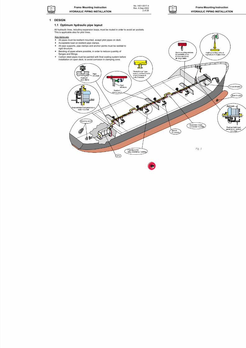
7/16/2019 Pompe Framo
http://slidepdf.com/reader/full/pompe-framo 123/175
No. 1401-0017-4Rev. A Sep-2002
2 of 26
Framo Mounting Instruction
HYDRAULIC PIPING INSTALLATION
Framo Moun
HYDRAULIC PIP
1 DESIGN
1.1 Optimum hydraulic pipe layout
All hydraulic lines, including expansion loops, must be routed in order to avoid air pockets.This is applicable also for pilot lines.
Key items are:
• All pipes must be resilient mounted, except pilot pipes on deck.
• Acceptable load on resilient pipe clamps. • All pipe supports, pipe clamps and anchor points must be welded to
rigid structure.
• Bending of pipes where possible, in order to reduce quantity of flanges and fittings.
• Carbon steel pipes must be painted with final coating system beforeinstallation on open deck, to avoid corrosion in clamping zone.
Fig. 1
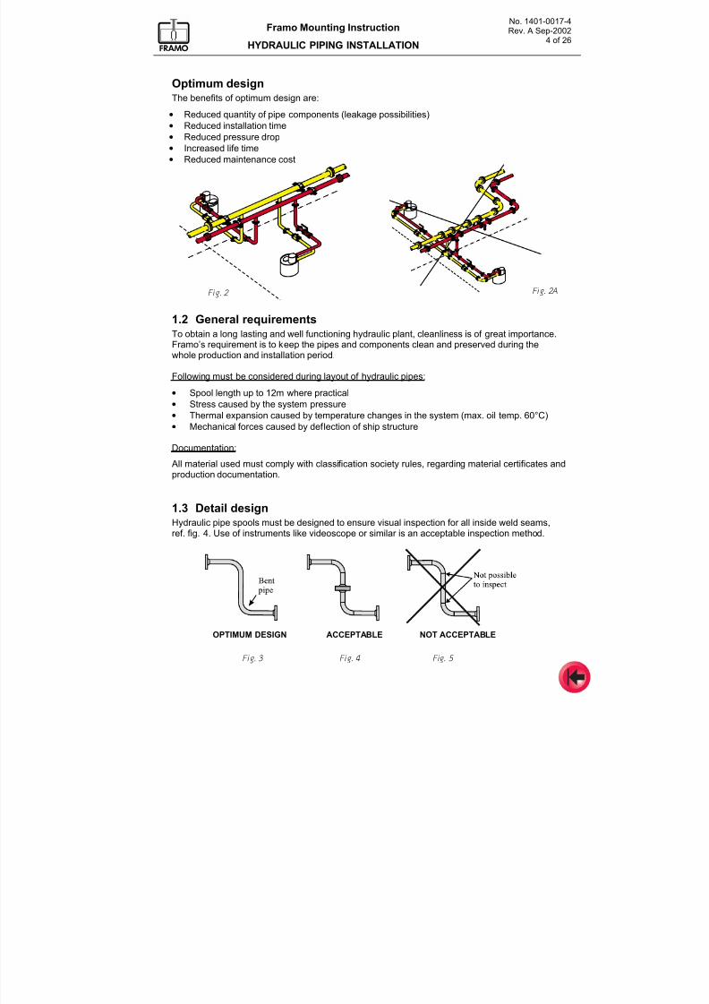
7/16/2019 Pompe Framo
http://slidepdf.com/reader/full/pompe-framo 124/175
No. 1401-0017-4Rev. A Sep-2002
4 of 26
Framo Mounting Instruction
HYDRAULIC PIPING INSTALLATION
Optimum designThe benefits of optimum design are:
• Reduced quantity of pipe components (leakage possibilities)
• Reduced installation time• Reduced pressure drop
• Increased life time
• Reduced maintenance cost
1.2 General requirementsTo obtain a long lasting and well functioning hydraulic plant, cleanliness is of great importance.Framo’s requirement is to keep the pipes and components clean and preserved during thewhole production and installation period.
Following must be considered during layout of hydraulic pipes:
• Spool length up to 12m where practical
• Stress caused by the system pressure
• Thermal expansion caused by temperature changes in the system (max. oil temp. 60°C)
• Mechanical forces caused by deflection of ship structure
Documentation:
All material used must comply with classification society rules, regarding material certificates andproduction documentation.
1.3 Detail designHydraulic pipe spools must be designed to ensure visual inspection for all inside weld seams,ref. fig. 4. Use of instruments like videoscope or similar is an acceptable inspection method.
Fig. 3 Fig. 4 Fig. 5
Fig. 2AFig. 2
OPTIMUM DESIGN ACCEPTABLE NOT ACCEPTABLE
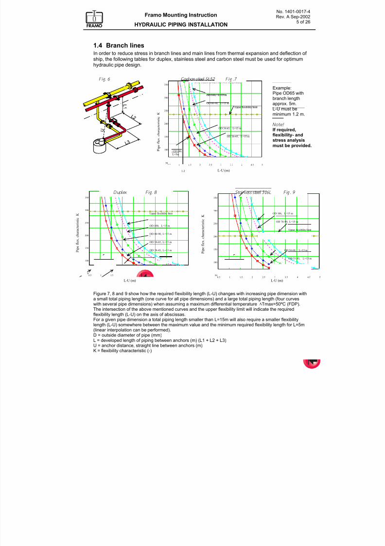
7/16/2019 Pompe Framo
http://slidepdf.com/reader/full/pompe-framo 125/175
No. 1401-0017-4Rev. A Sep-2002
5 of 26
Framo Mounting Instruction
HYDRAULIC PIPING INSTALLATION
1.4 Branch lines
In order to reduce stress in branch lines and main lines from thermal expansion and deflection of ship, the following tables for duplex, stainless steel and carbon steel must be used for optimum
hydraulic pipe design.
Figure 7, 8 and 9 show how the required flexibility length (L-U) changes with increasing pipe dimension witha small total piping length (one curve for all pipe dimensions) and a large total piping length (four curveswith several pipe dimensions) when assuming a maximum differential temperature ∆Tmax=50ºC (FDP).The intersection of the above mentioned curves and the upper flexibility limit will indicate the requiredflexibility length (L-U) on the axis of abscissas.For a given pipe dimension a total piping length smaller than L=15m will also require a smaller flexibilitylength (L-U) somewhere between the maximum value and the minimum required flexibility length for L=5m(linear interpolation can be performed).
D = outside diameter of pipe (mm)L = developed length of piping between anchors (m) (L1 + L2 + L3)U = anchor distance, straight line between anchors (m)K = flexibility characteristic (-)
0.5 1 1.5 2 2.5 3 3.5 4 4.5 550
100
150
200
250
300
350AISI 316L: FLEX ANALYSIS NOT REQUIRED?
0.5 1 1.5 2 2.5 3 3.5 4 4.5 550
100
150
200
250
300
35022Cr DUPLEX: FLEX ANALYSIS NOT REQUIRED?
0
0
j
j
P i p e f l e x . c h a r a c t e r i s t i c
K
P i p e f l e x . c h a r a c t e r i s t i c
KUpper flexibility limit
L-U (m) L-U (m)
OD 100, L=15 m
OD 80-90, L=15 m
OD 54-65, L=15 m
OD 38-45, L=15 m
< OD 106, L=5 m
Upper flexibility limit
OD 106, L=15 m
OD 76-90, L=15 m
OD 54-60, L=15 m
OD 35-45, L=15 m
< OD 106, L=5 m
Duplex Fig. 8 Stainless steel 316L Fi g. 9
0.5 1 1.5 2 2.5 3 3.5 4 4.5 550
100
150
200
250
300
350St 52: FLEX ANALYSIS NOT REQUIRED?
1.2 L-U (m)
Fig. 6 Carbon steel St.52 Fi g .7
P i p e f l e x . c
h a r a c t e r i s t i c
K
Upper flexibility limit
OD 100, L=15 m
OD 80-90, L=15 m
OD 54-65, L=15 m
OD 38-45, L=15 m
<OD100,L=5m
Example:Pipe OD65 withbranch lengthapprox. 5m.L-U must beminimum 1.2 m.
Note! If required,
flexibility- andstress analysis
must be provided.
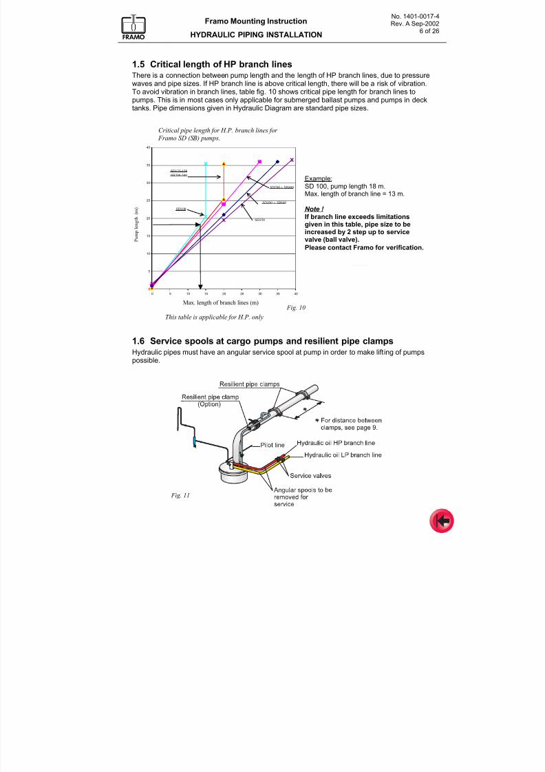
7/16/2019 Pompe Framo
http://slidepdf.com/reader/full/pompe-framo 126/175
No. 1401-0017-4Rev. A Sep-2002
6 of 26
Framo Mounting Instruction
HYDRAULIC PIPING INSTALLATION
1.5 Critical length of HP branch linesThere is a connection between pump length and the length of HP branch lines, due to pressurewaves and pipe sizes. If HP branch line is above critical length, there will be a risk of vibration.
To avoid vibration in branch lines, table fig. 10 shows critical pipe length for branch lines topumps. This is in most cases only applicable for submerged ballast pumps and pumps in decktanks. Pipe dimensions given in Hydraulic Diagram are standard pipe sizes.
1.6 Service spools at cargo pumps and resilient pipe clampsHydraulic pipes must have an angular service spool at pump in order to make lifting of pumpspossible.
Fig. 11
KRITISKE STIKKRØRSLENGDER FOR FRAMO SD(SB) PUMPER , BASERT PÅ SIMULERING
0
5
10
15
20
25
30
35
40
0 5 10 15 20 25 30 35 40
MAX. LENGDE STIKKRØR I METER
P U M P E L E N G D E
I M E T E R
Max. length of branch lines (m)
This table is applicable for H.P. only
P u m p l e n g t h
( m )
Critical pipe length for H.P. branch lines for
Framo SD (SB) pumps.
Example:SD 100, pump length 18 m.Max. length of branch line = 13 m.
Note !
If branch line exceeds limitationsgiven in this table, pipe size to beincreased by 2 step up to servicevalve (ball valve).Please contact Framo for verification.
SD350
SD300 + SB600
SD200 + SB400
SD100
SD125-150
SB200-300
Fig. 10
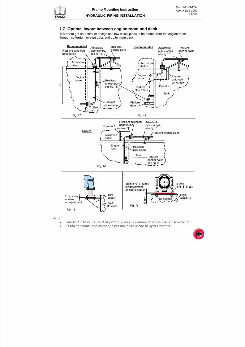
7/16/2019 Pompe Framo
http://slidepdf.com/reader/full/pompe-framo 127/175
No. 1401-0017-4Rev. A Sep-2002
7 of 26
Framo Mounting Instruction
HYDRAULIC PIPING INSTALLATION
1.7 Optimal layout between engine room and deckIn order to get an optimum design and low noise, pipes to be routed from the engine room,through cofferdam or pipe duct, and up to main deck.
Note!
• Length “L” to be as short as poss ib le, and m aximum 8m wi thout expansion bend.
• Resi l ient c lamps and anchor points must be welded to r ig id structure.
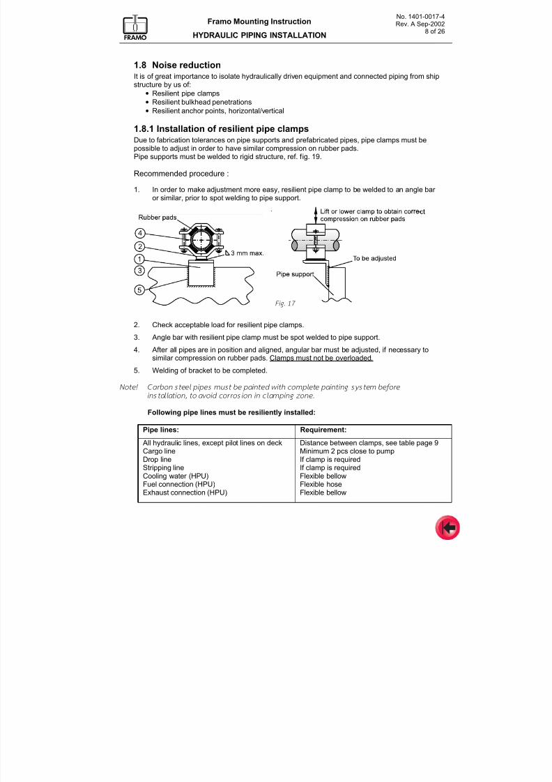
7/16/2019 Pompe Framo
http://slidepdf.com/reader/full/pompe-framo 128/175
No. 1401-0017-4Rev. A Sep-2002
8 of 26
Framo Mounting Instruction
HYDRAULIC PIPING INSTALLATION
1.8 Noise reductionIt is of great importance to isolate hydraulically driven equipment and connected piping from shipstructure by us of:
•
Resilient pipe clamps• Resilient bulkhead penetrations
• Resilient anchor points, horizontal/vertical
1.8.1 Installation of resilient pipe clampsDue to fabrication tolerances on pipe supports and prefabricated pipes, pipe clamps must bepossible to adjust in order to have similar compression on rubber pads.Pipe supports must be welded to rigid structure, ref. fig. 19.
Recommended procedure :
1. In order to make adjustment more easy, resilient pipe clamp to be welded to an angle bar or similar, prior to spot welding to pipe support.
2. Check acceptable load for resilient pipe clamps.
3. Angle bar with resilient pipe clamp must be spot welded to pipe support.
4. After all pipes are in position and aligned, angular bar must be adjusted, if necessary tosimilar compression on rubber pads. Clamps must not be overloaded.
5. Welding of bracket to be completed.
Note! Carbon steel pipes mu st be painted with comp lete paint ing system before instal lat ion, to avoid corros ion in clamping zone.
Following pipe lines must be resiliently installed:
Pipe lines: Requirement:
All hydraulic lines, except pilot lines on deckCargo lineDrop lineStripping lineCooling water (HPU)
Fuel connection (HPU)Exhaust connection (HPU)
Distance between clamps, see table page 9Minimum 2 pcs close to pumpIf clamp is requiredIf clamp is requiredFlexible bellow
Flexible hoseFlexible bellow
Fig. 17
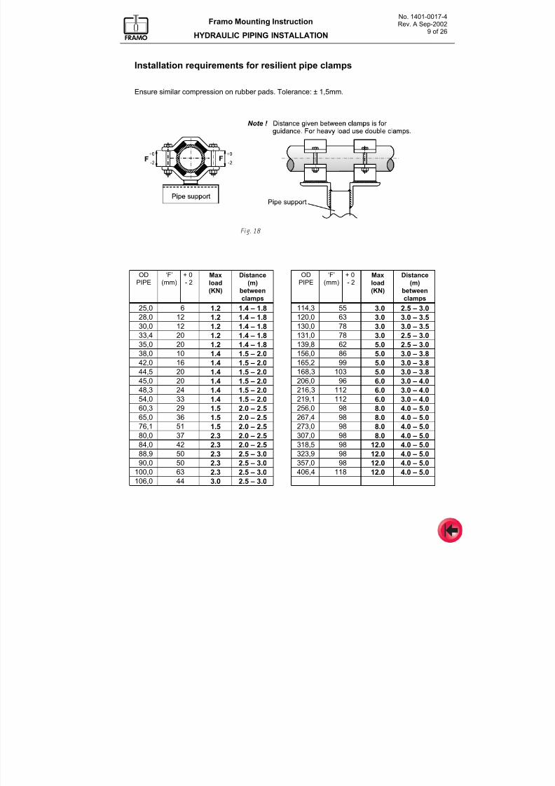
7/16/2019 Pompe Framo
http://slidepdf.com/reader/full/pompe-framo 129/175
No. 1401-0017-4Rev. A Sep-2002
9 of 26
Framo Mounting Instruction
HYDRAULIC PIPING INSTALLATION
Installation requirements for resilient pipe clamps
Ensure similar compression on rubber pads. Tolerance: ± 1,5mm.
ODPIPE
‘F’(mm)
+ 0- 2
Max
load
(KN)
Distance
(m)
betweenclamps
ODPIPE
‘F’(mm)
+ 0- 2
Max
load
(KN)
Distance
(m)
betweenclamps
25,0 6 1.2 1.4 – 1.8 114,3 55 3.0 2.5 – 3.0
28,0 12 1.2 1.4 – 1.8 120,0 63 3.0 3.0 – 3.5
30,0 12 1.2 1.4 – 1.8 130,0 78 3.0 3.0 – 3.5
33,4 20 1.2 1.4 – 1.8 131,0 78 3.0 2.5 – 3.0
35,0 20 1.2 1.4 – 1.8 139,8 62 5.0 2.5 – 3.0
38,0 10 1.4 1.5 – 2.0 156,0 86 5.0 3.0 – 3.8
42,0 16 1.4 1.5 – 2.0 165,2 99 5.0 3.0 – 3.8
44,5 20 1.4 1.5 – 2.0 168,3 103 5.0 3.0 – 3.8
45,0 20 1.4 1.5 – 2.0 206,0 96 6.0 3.0 – 4.0
48,3 24 1.4 1.5 – 2.0 216,3 112 6.0 3.0 – 4.054,0 33 1.4 1.5 – 2.0 219,1 112 6.0 3.0 – 4.0
60,3 29 1.5 2.0 – 2.5 256,0 98 8.0 4.0 – 5.0
65,0 36 1.5 2.0 – 2.5 267,4 98 8.0 4.0 – 5.0
76,1 51 1.5 2.0 – 2.5 273,0 98 8.0 4.0 – 5.0
80,0 37 2.3 2.0 – 2.5 307,0 98 8.0 4.0 – 5.0
84,0 42 2.3 2.0 – 2.5 318,5 98 12.0 4.0 – 5.0
88,9 50 2.3 2.5 – 3.0 323,9 98 12.0 4.0 – 5.0
90,0 50 2.3 2.5 – 3.0 357,0 98 12.0 4.0 – 5.0
100,0 63 2.3 2.5 – 3.0 406,4 118 12.0 4.0 – 5.0
106,0 44 3.0 2.5 – 3.0
Fig. 18
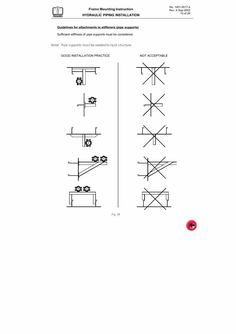
7/16/2019 Pompe Framo
http://slidepdf.com/reader/full/pompe-framo 130/175
No. 1401-0017-4Rev. A Sep-2002
10 of 26
Framo Mounting Instruction
HYDRAULIC PIPING INSTALLATION
Guidelines for attachments to stiffeners (pipe supports)
Sufficient stiffness of pipe supports must be considered.
Note! Pipe supports mu st be welded to r ig id structure.
GOOD INSTALLATION PRACTICE NOT ACCEPTABLE
Fig. 19
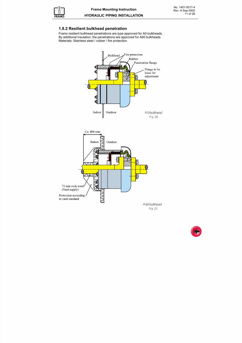
7/16/2019 Pompe Framo
http://slidepdf.com/reader/full/pompe-framo 131/175
No. 1401-0017-4Rev. A Sep-2002
11 of 26
Framo Mounting Instruction
HYDRAULIC PIPING INSTALLATION
1.8.2 Resilient bulkhead penetrationFramo resilient bulkhead penetrations are type approved for A0 bulkheads.By additional insulation, the penetrations are approved for A60 bulkheads.
Materials: Stainless steel / rubber / fire protection.
Fig. 20
Fig. 21
A0-bulkhead
A60-bulkhead
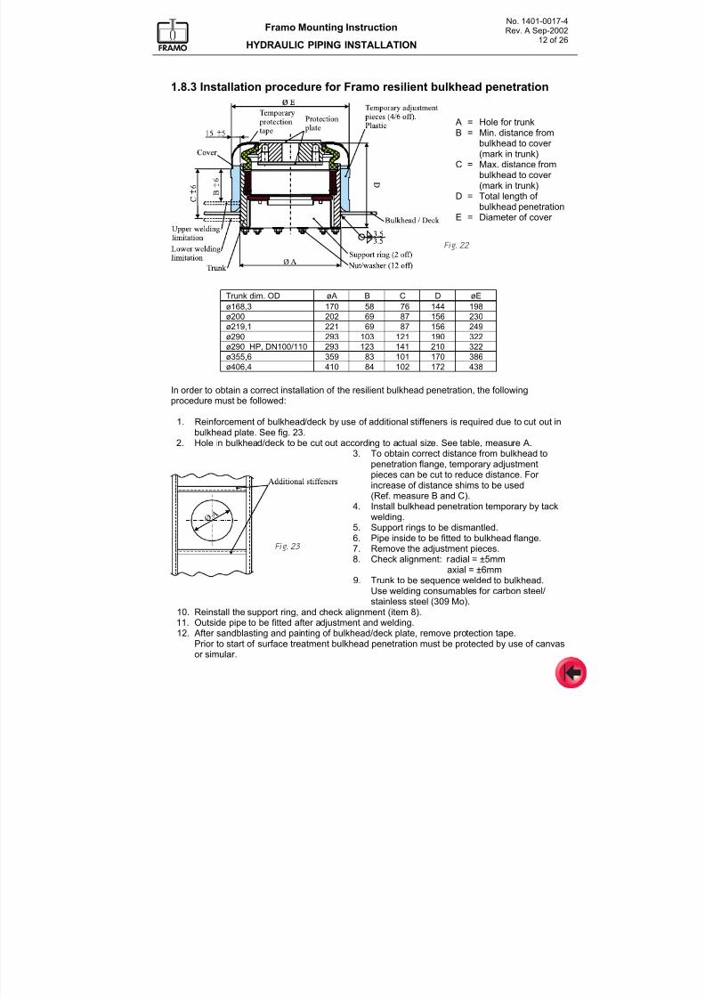
7/16/2019 Pompe Framo
http://slidepdf.com/reader/full/pompe-framo 132/175
No. 1401-0017-4Rev. A Sep-2002
12 of 26
Framo Mounting Instruction
HYDRAULIC PIPING INSTALLATION
1.8.3 Installation procedure for Framo resilient bulkhead penetration
In order to obtain a correct installation of the resilient bulkhead penetration, the followingprocedure must be followed:
1. Reinforcement of bulkhead/deck by use of additional stiffeners is required due to cut out inbulkhead plate. See fig. 23.
2. Hole in bulkhead/deck to be cut out according to actual size. See table, measure A.3. To obtain correct distance from bulkhead to
penetration flange, temporary adjustmentpieces can be cut to reduce distance. For increase of distance shims to be used
(Ref. measure B and C).4. Install bulkhead penetration temporary by tack
welding.5. Support rings to be dismantled.6. Pipe inside to be fitted to bulkhead flange.7. Remove the adjustment pieces.8. Check alignment: radial = ±5mm
axial = ±6mm9. Trunk to be sequence welded to bulkhead.
Use welding consumables for carbon steel/stainless steel (309 Mo).
10. Reinstall the support ring, and check alignment (item8
).11. Outside pipe to be fitted after adjustment and welding.12. After sandblasting and painting of bulkhead/deck plate, remove protection tape.
Prior to start of surface treatment bulkhead penetration must be protected by use of canvasor simular.
Trunk dim. OD øA B C D øE
ø168,3 170 58 76 144 198
ø200 202 69 87 156 230
ø219,1 221 69 87 156 249
ø290 293 103 121 190 322
ø290 HP, DN100/110 293 123 141 210 322
ø355,6 359 83 101 170 386
ø406,4 410 84 102 172 438
Fig. 22
Fig. 23
A = Hole for trunkB = Min. distance from
bulkhead to cover (mark in trunk)
C = Max. distance frombulkhead to cover (mark in trunk)
D = Total length of bulkhead penetration
E = Diameter of cover
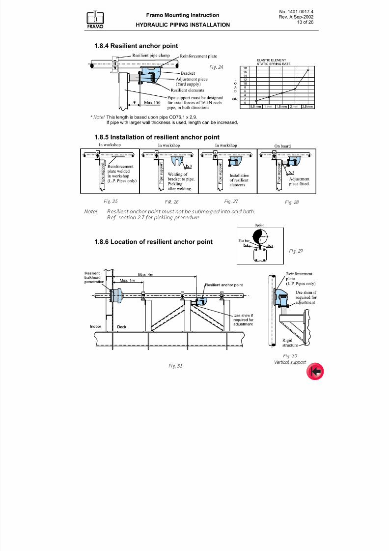
7/16/2019 Pompe Framo
http://slidepdf.com/reader/full/pompe-framo 133/175
No. 1401-0017-4Rev. A Sep-2002
13 of 26
Framo Mounting Instruction
HYDRAULIC PIPING INSTALLATION
1.8.4 Resilient anchor point
1.8.5 Installation of resilient anchor point
Note! Resi l ient anchor point must not be submerged into ac id bath.
Ref. sect ion 2.7 for pick l ing pr ocedure.
1.8.6 Location of resilient anchor point
Fig. 26
Fig. 24
Fig. 28 Fig. 27
Fig. 31
Fig. 25
Vertical support
Fig. 30
* Note! This length is based upon pipe OD76,1 x 2,9.If pipe with larger wall thickness is used, length can be increased.
Fig. 29
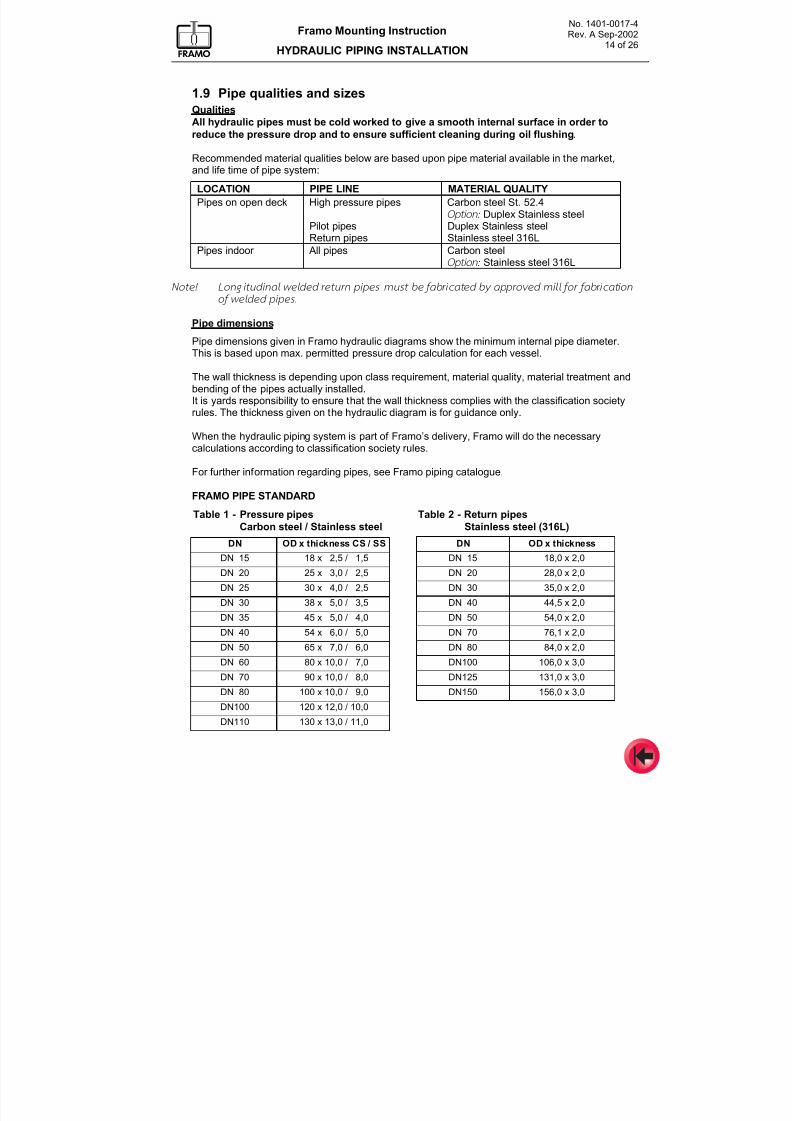
7/16/2019 Pompe Framo
http://slidepdf.com/reader/full/pompe-framo 134/175
No. 1401-0017-4Rev. A Sep-2002
14 of 26
Framo Mounting Instruction
HYDRAULIC PIPING INSTALLATION
1.9 Pipe qualities and sizes
Qualities
All hydraulic pipes must be cold worked to give a smooth internal surface in order to
reduce the pressure drop and to ensure sufficient cleaning during oil flushing.
Recommended material qualities below are based upon pipe material available in the market,and life time of pipe system:
LOCATION PIPE LINE MATERIAL QUALITY
Pipes on open deck High pressure pipes Carbon steel St. 52.4Option: Duplex Stainless steel
Pilot pipes Duplex Stainless steelReturn pipes Stainless steel 316L
Pipes indoor All pipes Carbon steelOption: Stainless steel 316L
Note! Longi tudinal welded return pipes must be fabr icated by approved mi l l for fabr icat ion
of w elded p ipes.
Pipe dimensions
Pipe dimensions given in Framo hydraulic diagrams show the minimum internal pipe diameter.This is based upon max. permitted pressure drop calculation for each vessel.
The wall thickness is depending upon class requirement, material quality, material treatment andbending of the pipes actually installed.It is yards responsibility to ensure that the wall thickness complies with the classification society
rules. The thickness given on the hydraulic diagram is for guidance only.
When the hydraulic piping system is part of Framo’s delivery, Framo will do the necessarycalculations according to classification society rules.
For further information regarding pipes, see Framo piping catalogue.
FRAMO PIPE STANDARD
Table 1 - Pressure pipes
Carbon steel / Stainless steel
Table 2 - Return pipes
Stainless steel (316L)
DN OD x thickness CS / SS DN OD x thickness
DN 15 18 x 2,5 / 1,5 DN 15 18,0 x 2,0
DN 20 25 x 3,0 / 2,5 DN 20 28,0 x 2,0
DN 25 30 x 4,0 / 2,5 DN 30 35,0 x 2,0
DN 30 38 x 5,0 / 3,5 DN 40 44,5 x 2,0
DN 35 45 x 5,0 / 4,0 DN 50 54,0 x 2,0
DN 40 54 x 6,0 / 5,0 DN 70 76,1 x 2,0
DN 50 65 x 7,0 / 6,0 DN 80 84,0 x 2,0
DN 60 80 x 10,0 / 7,0 DN100 106,0 x 3,0
DN 70 90 x 10,0 / 8,0 DN125 131,0 x 3,0
DN 80 100 x 10,0 / 9,0 DN150 156,0 x 3,0DN100 120 x 12,0 / 10,0
DN110 130 x 13,0 / 11,0
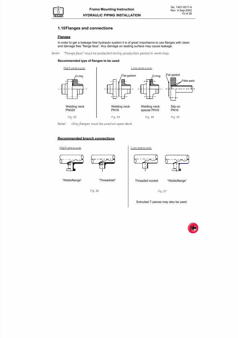
7/16/2019 Pompe Framo
http://slidepdf.com/reader/full/pompe-framo 135/175
No. 1401-0017-4Rev. A Sep-2002
15 of 26
Framo Mounting Instruction
HYDRAULIC PIPING INSTALLATION
1.10 Flanges and connections
Flanges
In order to get a leakage free hydraulic system it is of great importance to use flanges with cleanand damage free “flange face”. Any damage on sealing surface may cause leakage.
Note! “Flange face” must be protected dur ing product ion period in worksho p.
Recommended type of flanges to be used:
High pressure: Low pressure:
O-ring Flat gasket O-ring
Fillet weld
Flat gasket
Welding neck Welding neck Welding neck Slip-onPN320 PN16 special PN16 PN16
Fig. 32 Fig. 33 Fig. 34 Fig. 35
Note! Only f langes must be used on open deck.
Recommended branch connections
High pressure:
“Weldoflange” “Threadolet”
Fig. 36
Low p ressure:
Threaded socket “Weldoflange”
Fig. 37
Extruded T-pieces may also be used.
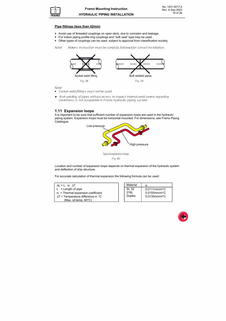
7/16/2019 Pompe Framo
http://slidepdf.com/reader/full/pompe-framo 136/175
No. 1401-0017-4Rev. A Sep-2002
16 of 26
Framo Mounting Instruction
HYDRAULIC PIPING INSTALLATION
Pipe fittings (less than 42mm)
• Avoid use of threaded couplings on open deck, due to corrosion and leakage.
• For indoor piping profile ring couplings and “soft seal” type may be used.
• Other types of couplings can be used, subject to approval from classification society.
Note! Makers instru ct ion mu st be careful ly fol low ed for correct instal lat ion.
Socket weld fitting Butt welded pipes
Fig. 38 Fig. 39
Note!
• Socket weld f i t tings m ust not b e used.
• •• • Butt w eld ing of pipes w i thout access to inspect internal weld seams regard ing
cleanl iness is not acceptable in Framo hydraul ic pip ing system .
1.11 Expansion loops
It is important to be sure that sufficient number of expansion loops are used in the hydraulic
piping system. Expansion loops must be horizontal mounted. For dimensions, see Framo PipingCatalogue.
Low pressure
High pressure
Location and number of expansion loops depends on thermal expansion of the hydraulic systemand deflection of ship structure.
For accurate calculation of thermal expansion the following formula can be used:
∆L = L ⋅ α ⋅ ∆T Material α L = Length of pipe
α = Thermal expansion coefficient
∆T = Temperature difference in °C
(Max. oil temp. 60°C)
St. 52316LDuplex
0,0111mm/m°C
0,0155mm/m°C
0,0135mm/m°C
Typical expansion loops
Fig. 40
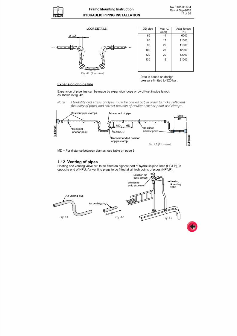
7/16/2019 Pompe Framo
http://slidepdf.com/reader/full/pompe-framo 137/175
No. 1401-0017-4Rev. A Sep-2002
17 of 26
Framo Mounting Instruction
HYDRAULIC PIPING INSTALLATION
LOOP DETAILS: OD pipe Max ∆L(mm)
Axial forces(N)
65
8090
100
120
130
14
1722
25
20
19
6000
1100011000
12000
13000
21000
Fig. 41 (Plan view)
Data is based on designpressure limited to 320 bar.
Expansion of pipe line
Expansion of pipe line can be made by expansion loops or by off-set in pipe layout,as shown in fig. 42.
Note! Flexibi l i ty and stress analysis mu st be carr ied out, in order to make suff ic ient
f lex ib i l i ty of pipes and correct pos i t ion o f res i l ient anchor point and clamps.
MD = For distance between clamps, see table on page 9.
1.12 Venting of pipes
Heating and venting valve arr. to be fitted on highest part of hydraulic pipe lines (HP/LP), inopposite end of HPU. Air venting plugs to be fitted at all high points of pipes (HP/LP).
Fig. 42 (Plan view)
Fig. 43 Fig. 45 Fig. 44
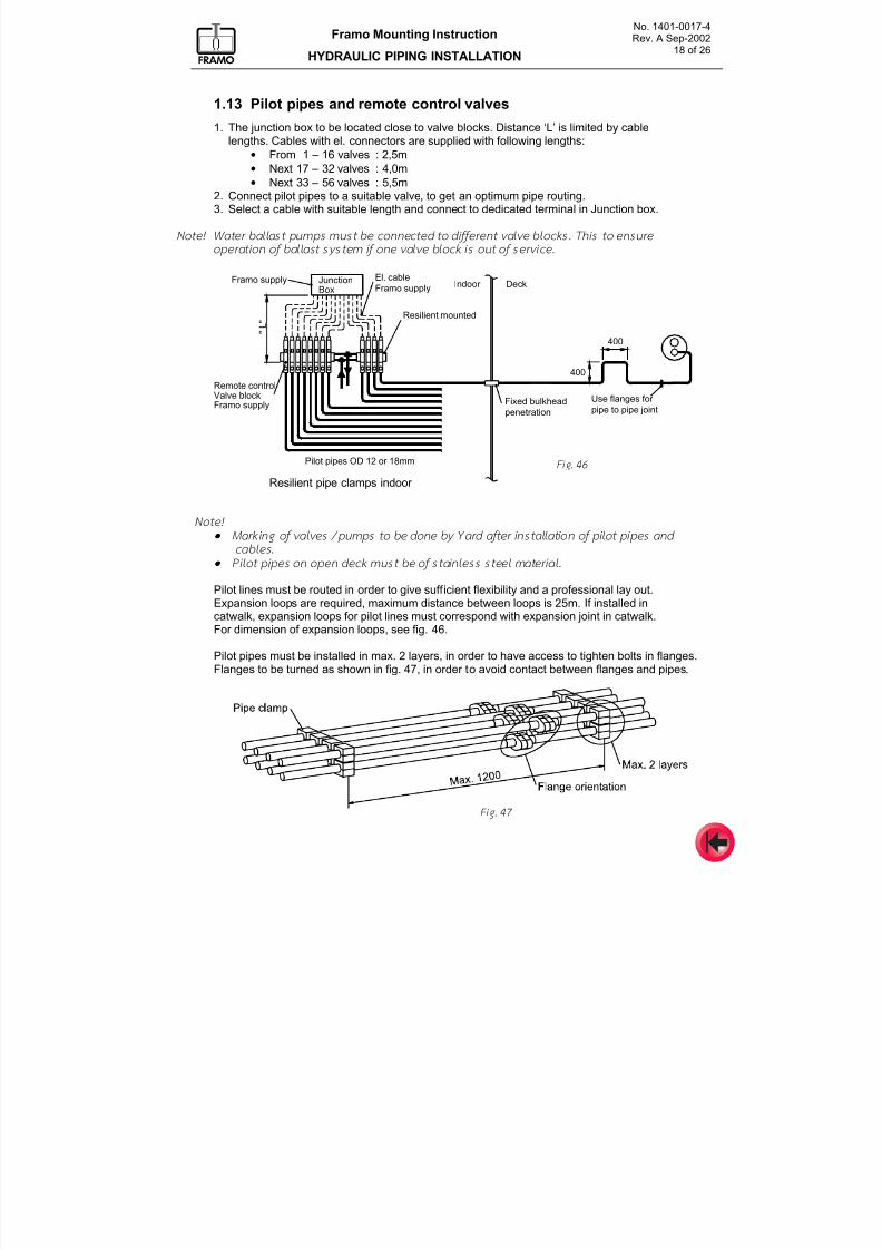
7/16/2019 Pompe Framo
http://slidepdf.com/reader/full/pompe-framo 138/175
No. 1401-0017-4Rev. A Sep-2002
18 of 26
Framo Mounting Instruction
HYDRAULIC PIPING INSTALLATION
1.13 Pilot pipes and remote control valves
1. The junction box to be located close to valve blocks. Distance ‘L’ is limited by cablelengths. Cables with el. connectors are supplied with following lengths:
• From 1 – 16 valves : 2,5m• Next 17 – 32 valves : 4,0m
• Next 33 – 56 valves : 5,5m2. Connect pilot pipes to a suitable valve, to get an optimum pipe routing.3. Select a cable with suitable length and connect to dedicated terminal in Junction box.
Note! Water bal last pumps m ust be connected to dif ferent valve block s. This to ensur e
operat ion of bal last system if on e valve block is ou t of service.
Resilient pipe clamps indoor
Pilot pipes OD 12 or 18mm
Fixed bulkhead
penetration
400
400
Use flanges for
pipe to pipe joint
JunctionBox
Resilient mounted
Indoor DeckEl. cable
Framo supplyFramo supply
" L "
Remote controlValve blockFramo supply
Note!
• •• • Marking of valves / pum ps to be don e by Yard after instal lat ion of p i lot pipes and
cables.
• •• • Pilot pipes on op en deck mus t be of stainless steel material.
Pilot lines must be routed in order to give sufficient flexibility and a professional lay out.Expansion loops are required, maximum distance between loops is 25m. If installed in
catwalk, expansion loops for pilot lines must correspond with expansion joint in catwalk.For dimension of expansion loops, see fig. 46.
Pilot pipes must be installed in max. 2 layers, in order to have access to tighten bolts in flanges.Flanges to be turned as shown in fig. 47, in order to avoid contact between flanges and pipes.
Fig. 46
Fig. 47
Resilient pipe clamps indoor
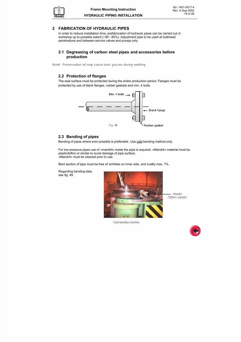
7/16/2019 Pompe Framo
http://slidepdf.com/reader/full/pompe-framo 139/175
No. 1401-0017-4Rev. A Sep-2002
19 of 26
Framo Mounting Instruction
HYDRAULIC PIPING INSTALLATION
2 FABRICATION OF HYDRAULIC PIPESIn order to reduce installation time, prefabrication of hydraulic pipes can be carried out inworkshop up to possible extent (~80 - 85%). Adjustment pipe to be used at bulkhead
penetrations and between service valves and pumps only.
2.1 Degreasing of carbon steel pipes and accessories before
production
Note! Preservat ion oi l may cause toxic gasses durin g welding.
2.2 Protection of flangesThe seal surface must be protected during the entire production period. Flanges must be
protected by use of blank flanges, rubber gaskets and min. 4 bolts.
2.3 Bending of pipesBending of pipes where ever possible is preferable. Use cold bending method only.
For low pressure pipes use of «mandril» inside the pipe is required. «Mandril» material must beplastic/teflon or similar to avoid damage of pipe surface.«Mandril» must be cleaned prior to use.
Bent section of pipe must be free of wrinkles on inner side, and ovality max. 7%.
Regarding bending data,see fig. 49.
Mandril
(Teflon / plastic).
Fig. 48
Cold bending machine
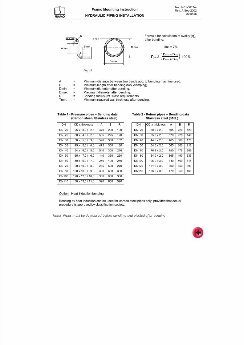
7/16/2019 Pompe Framo
http://slidepdf.com/reader/full/pompe-framo 140/175
No. 1401-0017-4Rev. A Sep-2002
20 of 26
Framo Mounting Instruction
HYDRAULIC PIPING INSTALLATION
A minB min
T min
D max
D min
R
Formula for calculation of ovality (η),
after bending:
Limit = 7%
η = ⋅−
+
æ è ç
ö ø÷ ⋅2 100%
D D
D D
max min
max min
Fig. 49
A = Minimum distance between two bends acc. to bending machine used.
B = Minimum length after bending (tool clamping).Dmin. = Minimum diameter after bending.Dmax. = Maximum diameter after bending.R = Bending radius, ref. class requirements.Tmin. = Minimum required wall thickness after bending.
Table 1 - Pressure pipes – Bending data
(Carbon steel / Stainless steel)
Table 2 - Return pipes – Bending data
Stainless steel (316L)
DN OD x thickness A B R DN OD x thickness A B R
DN 20 25 x 3,0 / 2,5 470 200 100 DN 20 30,0 x 2,0 505 220 120
DN 25 30 x 4,0 / 2,5 505 225 120 DN 30 35,0 x 2,0 570 225 140
DN 30 38 x 5,0 / 3,5 590 300 152 DN 40 44,5 x 2,0 465 300 178
DN 35 45 x 5,0 / 4,0 475 300 180 DN 50 54,0 x 2,0 565 300 216
DN 40 54 x 6,0 / 5,0 540 300 216 DN 70 76,1 x 2,0 790 475 305
DN 50 65 x 7,0 / 6,0 110 360 260 DN 80 84,0 x 2,0 865 490 335
DN 60 80 x 10,0 / 7,0 250 400 240 DN100 106,0 x 3,0 340 600 318
DN 70 90 x 10,0 / 8,0 285 500 270 DN125 131,0 x 3,0 300 650 393
DN 80 100 x 10,0 / 9,0 300 600 300 DN150 156,0 x 3,0 470 850 468
DN100 120 x 12,0 / 10,0 360 650 360
DN110 130 x 13,0 / 11,0 390 650 390
Option: Heat induction bending
Bending by heat induction can be used for carbon steel pipes only, provided that actualprocedure is approved by classification society.
Note! Pipes must be degreased before bending , and pickled after bending.
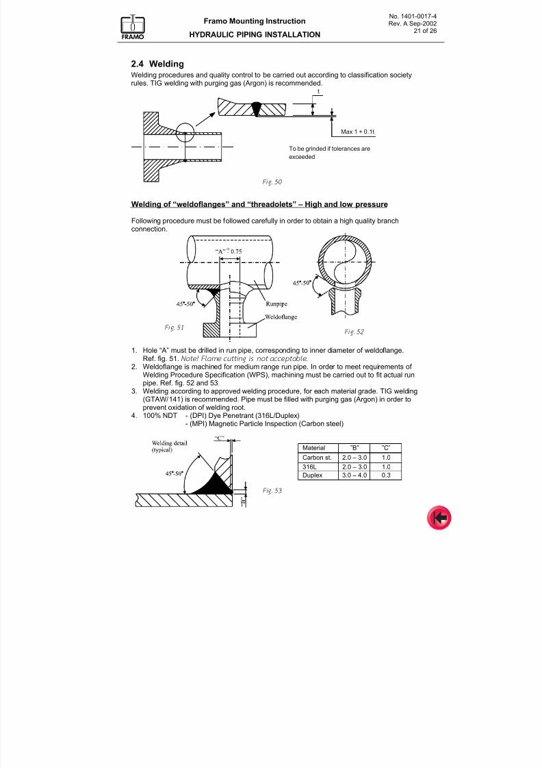
7/16/2019 Pompe Framo
http://slidepdf.com/reader/full/pompe-framo 141/175
No. 1401-0017-4Rev. A Sep-2002
21 of 26
Framo Mounting Instruction
HYDRAULIC PIPING INSTALLATION
2.4 WeldingWelding procedures and quality control to be carried out according to classification societyrules. TIG welding with purging gas (Argon) is recommended.
To be grinded if tolerances are
exceeded
t
Max 1 + 0.1t
Welding of “weldoflanges” and “threadolets” – High and low pressure
Following procedure must be followed carefully in order to obtain a high quality branchconnection.
1. Hole “A” must be drilled in run pipe, corresponding to inner diameter of weldoflange.Ref. fig. 51. Note! Flame cutt ing is not acceptable .
2. Weldoflange is machined for medium range run pipe. In order to meet requirements of Welding Procedure Specification (WPS), machining must be carried out to fit actual runpipe. Ref. fig. 52 and 53.
3. Welding according to approved welding procedure, for each material grade. TIG welding(GTAW/141) is recommended. Pipe must be filled with purging gas (Argon) in order toprevent oxidation of welding root.
4. 100% NDT - (DPI) Dye Penetrant (316L/Duplex)- (MPI) Magnetic Particle Inspection (Carbon steel)
Material ”B” ”C”
Carbon st. 2.0 – 3.0 1.0
316L 2.0 – 3.0 1.0
Duplex 3.0 – 4.0 0.3
Fig. 50
Fig. 51 Fig. 52
Fig. 53
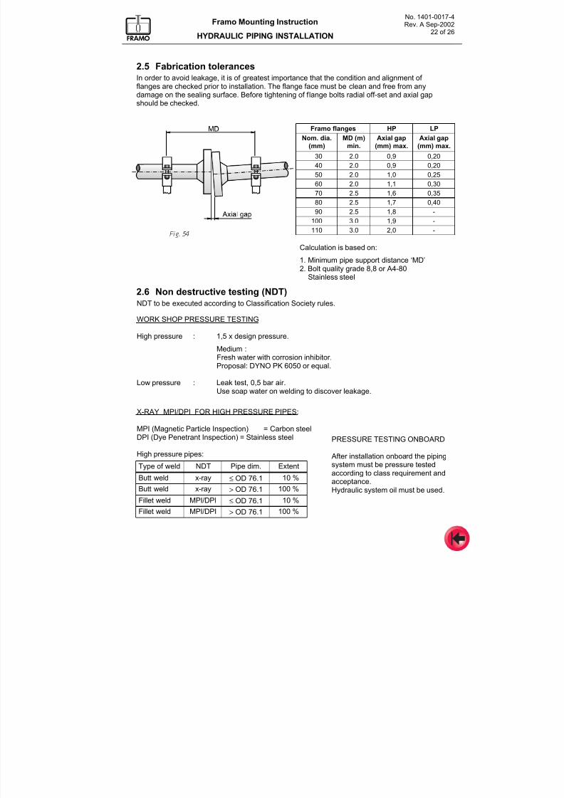
7/16/2019 Pompe Framo
http://slidepdf.com/reader/full/pompe-framo 142/175
No. 1401-0017-4Rev. A Sep-2002
22 of 26
Framo Mounting Instruction
HYDRAULIC PIPING INSTALLATION
2.5 Fabrication tolerancesIn order to avoid leakage, it is of greatest importance that the condition and alignment of flanges are checked prior to installation. The flange face must be clean and free from any
damage on the sealing surface. Before tightening of flange bolts radial off-set and axial gapshould be checked.
Fig. 54
2.6 Non destructive testing (NDT)NDT to be executed according to Classification Society rules.
WORK SHOP PRESSURE TESTING
High pressure : 1,5 x design pressure.
Medium :Fresh water with corrosion inhibitor.Proposal: DYNO PK 6050 or equal.
Low pressure : Leak test, 0,5 bar air.
Use soap water on welding to discover leakage.
X-RAY MPI/DPI FOR HIGH PRESSURE PIPES:
MPI (Magnetic Particle Inspection) = Carbon steelDPI (Dye Penetrant Inspection) = Stainless steel
High pressure pipes:
Type of weld NDT Pipe dim. Extent
Butt weld x-ray ≤ OD 76.1 10 %
Butt weld x-ray> OD 76.1
100 %
Fillet weld MPI/DPI ≤ OD 76.1 10 %
Fillet weld MPI/DPI > OD 76.1 100 %
Framo flanges HP LP
Nom. dia.
(mm)
MD (m)
min.
Axial gap
(mm) max.
Axial gap
(mm) max.
30 2.0 0,9 0,20
40 2.0 0,9 0,20
50 2.0 1,0 0,25
60 2.0 1,1 0,30
70 2.5 1,6 0,35
80 2.5 1,7 0,40
90 2.5 1,8 -
100 3.0 1,9 -
110 3.0 2,0 -
Calculation is based on:
1. Minimum pipe support distance ‘MD’2. Bolt quality grade 8,8 or A4-80
Stainless steel
PRESSURE TESTING ONBOARD
After installation onboard the pipingsystem must be pressure testedaccording to class requirement andacceptance.
Hydraulic system oil must be used.
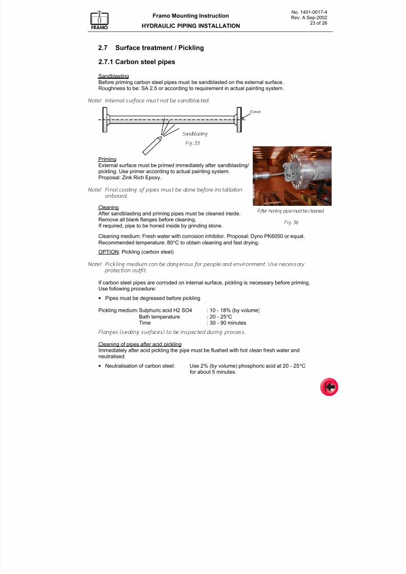
7/16/2019 Pompe Framo
http://slidepdf.com/reader/full/pompe-framo 143/175
No. 1401-0017-4Rev. A Sep-2002
23 of 26
Framo Mounting Instruction
HYDRAULIC PIPING INSTALLATION
2.7 Surface treatment / Pickling
2.7.1 Carbon steel pipes
SandblastingBefore priming carbon steel pipes must be sandblasted on the external surface.Roughness to be: SA 2.5 or according to requirement in actual painting system.
Note! Internal surface mu st not be sandblasted.
PrimingExternal surface must be primed immediately after sandblasting/pickling. Use primer according to actual painting system.Proposal: Zink Rich Epoxy.
Note! Final coat ing of pipes must be done before instal lat ion
onboard.
Cleaning
After sandblasting and priming pipes must be cleaned inside.Remove all blank flanges before cleaning.If required, pipe to be honed inside by grinding stone.
Cleaning medium: Fresh water with corrosion inhibitor. Proposal: Dyno PK6050 or equal.
Recommended temperature: 80°C to obtain cleaning and fast drying.
OPTION: Pickling (carbon steel)
Note! Pickl ing medium c an be dangerous for people and environm ent. Use necessary
protect ion out f i t .
If carbon steel pipes are corroded on internal surface, pickling is necessary before priming.Use following procedure:
• Pipes must be degreased before pickling
Pickling medium: Sulphuric acid H2 SO4 : 10 - 18% (by volume)
Bath temperature : 20 - 25°CTime : 30 - 90 minutes
Flanges (seal ing surfaces) to be inspected dur ing pro cess.
Cleaning of pipes after acid picklingImmediately after acid pickling the pipe must be flushed with hot clean fresh water and
neutralised.
• Neutralisation of carbon steel: Use 2% (by volume) phosphoric acid at 20 - 25°Cfor about 5 minutes.
Fig. 55
Fig. 56
Sandblasting
After honing pipe must be cleaned.
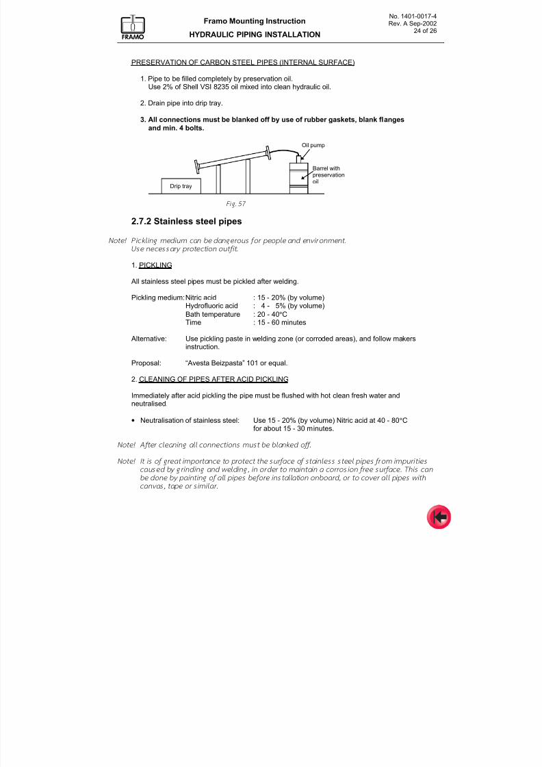
7/16/2019 Pompe Framo
http://slidepdf.com/reader/full/pompe-framo 144/175
No. 1401-0017-4Rev. A Sep-2002
24 of 26
Framo Mounting Instruction
HYDRAULIC PIPING INSTALLATION
PRESERVATION OF CARBON STEEL PIPES (INTERNAL SURFACE)
1. Pipe to be filled completely by preservation oil.Use 2% of Shell VSI 8235 oil mixed into clean hydraulic oil.
2. Drain pipe into drip tray.
3. All connections must be blanked off by use of rubber gaskets, blank flanges
and min. 4 bolts.
Drip tray
Oil pump
Barrel withpreservationoil
Fig. 57
2.7.2 Stainless steel pipes
Note! Pick l ing medium can be dangerous for people and envi ronment .
Use necessary protect ion o utf i t .
1. PICKLING
All stainless steel pipes must be pickled after welding.
Pickling medium: Nitric acid : 15 - 20% (by volume)Hydrofluoric acid : 4 - 5% (by volume)
Bath temperature : 20 - 40°CTime : 15 - 60 minutes
Alternative: Use pickling paste in welding zone (or corroded areas), and follow makersinstruction.
Proposal: “Avesta Beizpasta” 101 or equal.
2. CLEANING OF PIPES AFTER ACID PICKLING
Immediately after acid pickling the pipe must be flushed with hot clean fresh water andneutralised.
• Neutralisation of stainless steel: Use 15 - 20% (by volume) Nitric acid at 40 - 80°Cfor about 15 - 30 minutes.
Note! After cleaning al l conn ect ions mus t be blanked off .
Note! It is of great impor tance to protect the surface of stainless steel pipes from imp uri t ies
caused by grin ding and w elding, in order to maintain a corrosio n free surface. This can
be done by paint ing of al l pipes before instal lat ion on board, or to cover al l pipes with
canvas, tape or simi lar.
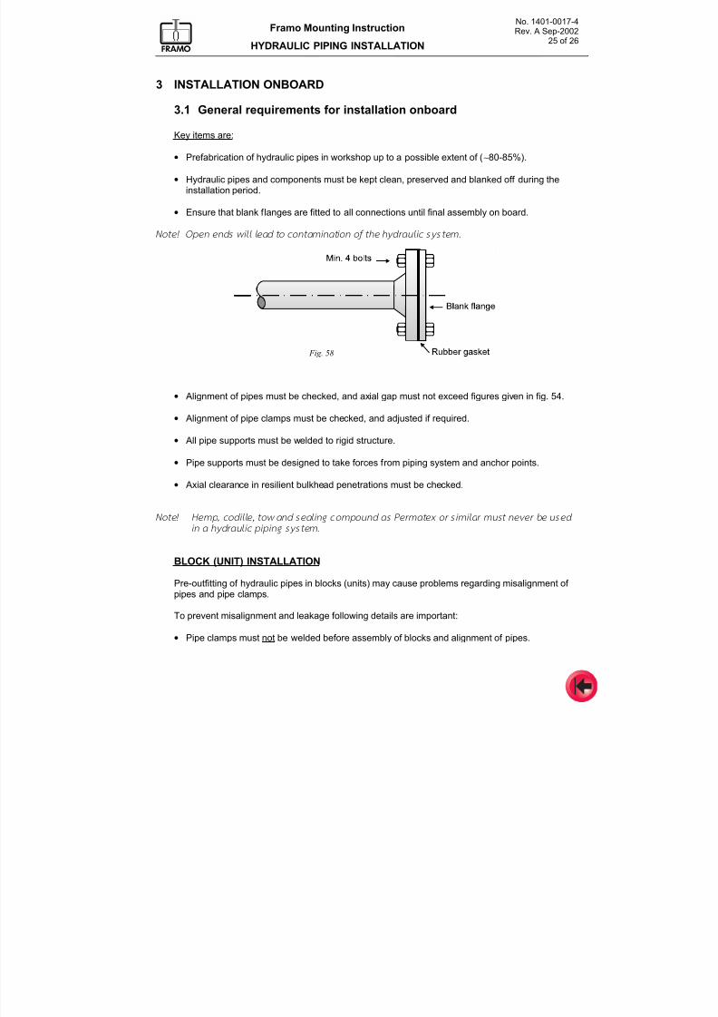
7/16/2019 Pompe Framo
http://slidepdf.com/reader/full/pompe-framo 145/175
No. 1401-0017-4Rev. A Sep-2002
25 of 26
Framo Mounting Instruction
HYDRAULIC PIPING INSTALLATION
3 INSTALLATION ONBOARD
3.1 General requirements for installation onboard
Key items are:
• Prefabrication of hydraulic pipes in workshop up to a possible extent of (∼80-85%).
• Hydraulic pipes and components must be kept clean, preserved and blanked off during theinstallation period.
• Ensure that blank flanges are fitted to all connections until final assembly on board.
Note! Open ends wi l l lead to contamination of the hydraul ic system.
• Alignment of pipes must be checked, and axial gap must not exceed figures given in fig. 54.
• Alignment of pipe clamps must be checked, and adjusted if required.
• All pipe supports must be welded to rigid structure.
• Pipe supports must be designed to take forces from piping system and anchor points.
• Axial clearance in resilient bulkhead penetrations must be checked.
Note! Hemp, codi l le , tow and seal ing comp ound as Permatex or s imi lar must never be used
in a hydraul ic p ip ing system.
BLOCK (UNIT) INSTALLATION
Pre-outfitting of hydraulic pipes in blocks (units) may cause problems regarding misalignment of pipes and pipe clamps.
To prevent misalignment and leakage following details are important:
• Pipe clamps must not be welded before assembly of blocks and alignment of pipes.
Fig. 58
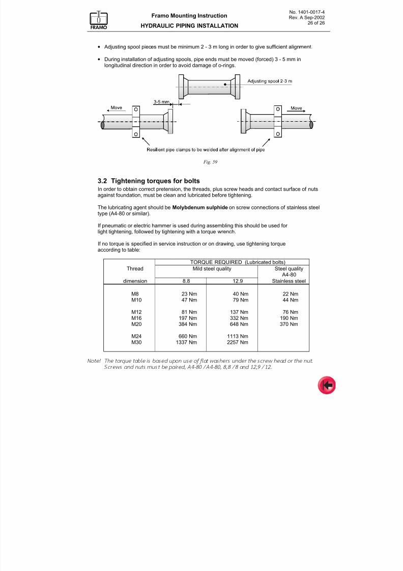
7/16/2019 Pompe Framo
http://slidepdf.com/reader/full/pompe-framo 146/175
No. 1401-0017-4Rev. A Sep-2002
26 of 26
Framo Mounting Instruction
HYDRAULIC PIPING INSTALLATION
• Adjusting spool pieces must be minimum 2 - 3 m long in order to give sufficient alignment.
• During installation of adjusting spools, pipe ends must be moved (forced) 3 - 5 mm inlongitudinal direction in order to avoid damage of o-rings.
Fig. 59
3.2 Tightening torques for boltsIn order to obtain correct pretension, the threads, plus screw heads and contact surface of nutsagainst foundation, must be clean and lubricated before tightening.
The lubricating agent should be Molybdenum sulphide on screw connections of stainless steel
type (A4-80 or similar).
If pneumatic or electric hammer is used during assembling this should be used for light tightening, followed by tightening with a torque wrench.
If no torque is specified in service instruction or on drawing, use tightening torqueaccording to table:
TORQUE REQUIRED (Lubricated bolts)
Thread Mild steel quality Steel quality A4-80
dimension 8.8 12.9 Stainless steel
M8 23 Nm 40 Nm 22 NmM10 47 Nm 79 Nm 44 Nm
M12 81 Nm 137 Nm 76 NmM16 197 Nm 332 Nm 190 NmM20 384 Nm 648 Nm 370 Nm
M24 660 Nm 1113 NmM30 1337 Nm 2257 Nm
Note! The torqu e table is based upon use of f lat wash ers under the screw h ead or the nut.
Screw s and nu ts m us t be pair ed, A4-80 / A4-80, 8,8 / 8 and 12,9 / 12.
7/16/2019 Pompe Framo
http://slidepdf.com/reader/full/pompe-framo 147/175
Framo
Mounting Instruction
CARGO PIPING
No. 1401-0018-4April 2000
CONTENTS
1. General
2. Chemical Carriers
3. Oil Product - and Crude Oil Tankers
4. Self-draining4.1 Cargo deck lines above manifold4.2 Cargo deck lines below manifold4.3 Drain arrangement for manifold
5. Cargo pump stripping arrangement5.1 Vacuum drain arrangement. (Option)
6. Resilient mounting6.1 Resilient pipe clamps
7/16/2019 Pompe Framo
http://slidepdf.com/reader/full/pompe-framo 148/175
Framo Mounting Instruction
CARGO PIPING
No. 1401-0018-4 April-2000
Page 2 of 12
1 GENERAL
This document is intended as a guide with some examples for possible cargo piping on
Chemical carriers, Oil product- and Crude oil tankers. Other design criteria may apply for FSOP’s and OBO’s.
The cargo piping arrangement will depend on type of vessel, cargoes to be carried and number of segregations, but should always be arranged for optimal efficiency regarding loading,discharging, draining and cleaning.
In addition to the different authorities and owner’s requirements, the following main items mustbe considered during design:
- Cargo piping material.- Segregation and a minimum risk of cargo contamination.
- Self-drainage or easy draining of piping and components.- Optimal arrangement and number of valves.- Valves. Type-Material-Operation (remote and/or local operation).- Number of flanges reduced to a minimum.- Easy access for operation and maintenance of equipment.- Service spools for dismantling and maintenance of equipment.- Maximum cargo pressure and equipment design pressure.- Mechanical forces from ship structure.- Anchor points and expansion loops.- Resilient pipe clamps close to the Framo cargo pumps.- Flexibility between Framo cargo pumps and cargo drop line.
From a stripping point of view, an arrangement with the manifolds (crossovers) below cargodeck lines, and with the deck lines sloping against the manifolds is preferred. From a loadingpoint of view, an arrangement with the manifolds above cargo deck lines is preferred.Plus- and minus for the different arrangements are given in page 6, and regardless of manifoldlocation, arrangements should be made to reduce or avoid the drawback of the selecteddesign.
Cargo can be loaded through the Framo submerged cargo pump, but the loadingcapacity/pressure is limited by an anti-rotation brake in the pump, (preventing the impeller fromrotating during loading).Separate cargo drop lines should always be installed to obtain a satisfactory loading rate, and
also to make it possible to by-pass the cargo pump during loading.
For cargo circulation (cargo heating with deck heaters or circulation of cargoes with highcontent of sediments), the drop line outlet in tank should be as far away from the cargo pumpinlet as possible.If limited space on deck, drop lines may be routed inside the cargo tank.
Pressure transducers for remote reading of cargo pressure should preferably be installedbetween the cargo pump and the cargo valve, making it possible to read the cargo pressurewhen the cargo pump is running, even with closed cargo valve.
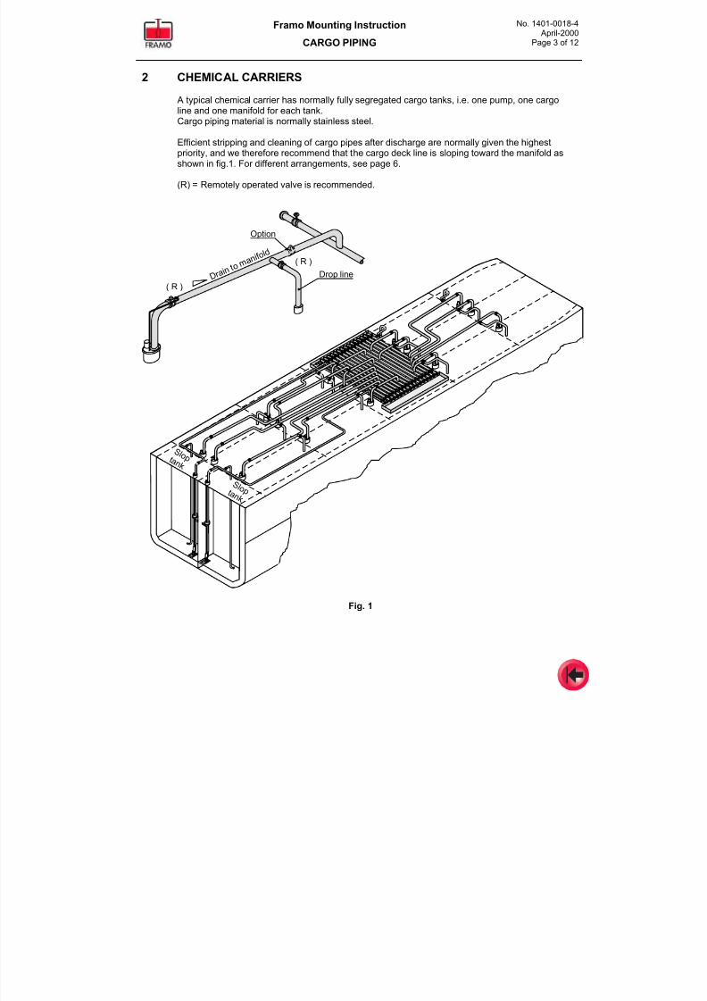
7/16/2019 Pompe Framo
http://slidepdf.com/reader/full/pompe-framo 149/175
Framo Mounting Instruction
CARGO PIPING
No. 1401-0018-4 April-2000
Page 3 of 12
2 CHEMICAL CARRIERS
A typical chemical carrier has normally fully segregated cargo tanks, i.e. one pump, one cargoline and one manifold for each tank.
Cargo piping material is normally stainless steel.
Efficient stripping and cleaning of cargo pipes after discharge are normally given the highestpriority, and we therefore recommend that the cargo deck line is sloping toward the manifold asshown in fig.1. For different arrangements, see page 6.
(R) = Remotely operated valve is recommended.
S l o p t a n k
Drop line D r a i n t o
m a n i f o
l d
( R )
( R )
Option
S l o p t a n k
Fig. 1
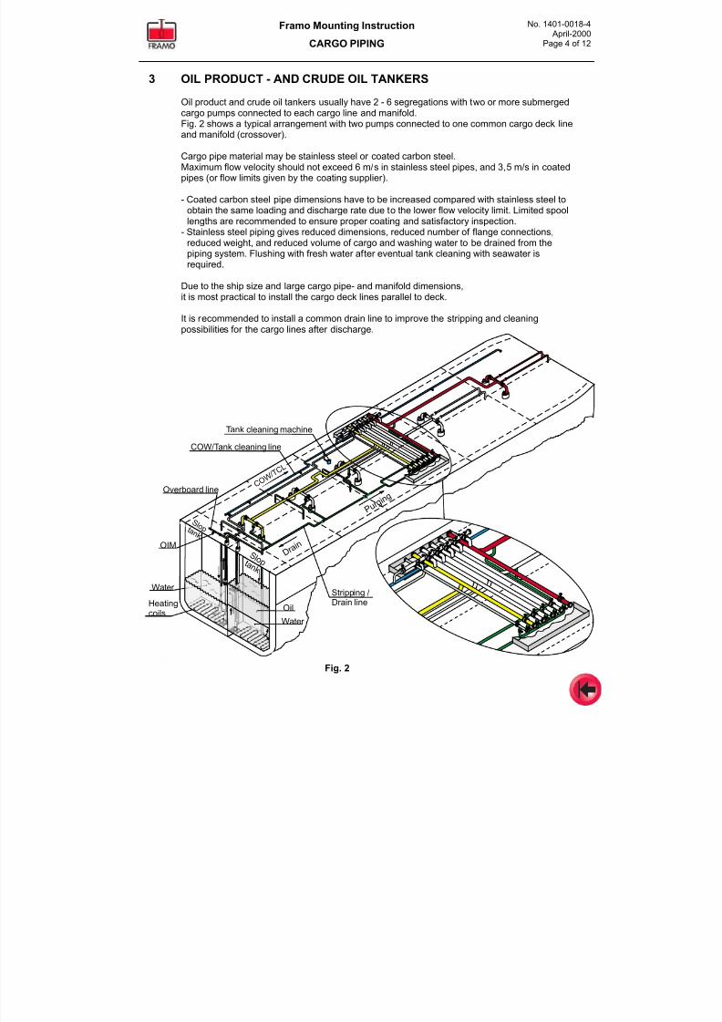
7/16/2019 Pompe Framo
http://slidepdf.com/reader/full/pompe-framo 150/175
Framo Mounting Instruction
CARGO PIPING
No. 1401-0018-4 April-2000
Page 4 of 12
3 OIL PRODUCT - AND CRUDE OIL TANKERS
Oil product and crude oil tankers usually have 2 - 6 segregations with two or more submergedcargo pumps connected to each cargo line and manifold.
Fig. 2 shows a typical arrangement with two pumps connected to one common cargo deck lineand manifold (crossover).
Cargo pipe material may be stainless steel or coated carbon steel.Maximum flow velocity should not exceed 6 m/s in stainless steel pipes, and 3,5 m/s in coatedpipes (or flow limits given by the coating supplier).
- Coated carbon steel pipe dimensions have to be increased compared with stainless steel toobtain the same loading and discharge rate due to the lower flow velocity limit. Limited spoollengths are recommended to ensure proper coating and satisfactory inspection.
- Stainless steel piping gives reduced dimensions, reduced number of flange connections,reduced weight, and reduced volume of cargo and washing water to be drained from the
piping system. Flushing with fresh water after eventual tank cleaning with seawater isrequired.
Due to the ship size and large cargo pipe- and manifold dimensions,it is most practical to install the cargo deck lines parallel to deck.
It is recommended to install a common drain line to improve the stripping and cleaningpossibilities for the cargo lines after discharge.
S l o p t a n k
D r a i n
S l o p t a n k
Overboard line
OIM
Water
Heatingcoils
Water
Oil
P u r g i n g
COW/Tank cleaning line
Tank cleaning machine
C O W /
T C L
Stripping /Drain line
Fig. 2
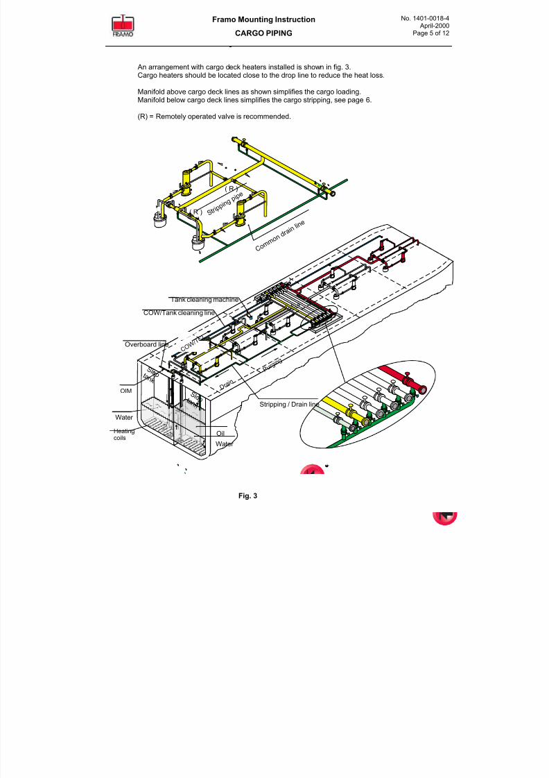
7/16/2019 Pompe Framo
http://slidepdf.com/reader/full/pompe-framo 151/175
Framo Mounting Instruction
CARGO PIPING
No. 1401-0018-4 April-2000
Page 5 of 12
An arrangement with cargo deck heaters installed is shown in fig. 3.Cargo heaters should be located close to the drop line to reduce the heat loss.
Manifold above cargo deck lines as shown simplifies the cargo loading.Manifold below cargo deck lines simplifies the cargo stripping, see page 6.
(R) = Remotely operated valve is recommended.
S l o p t a n k
D r a i n
S l o p t a n k
Overboard line
OIM
Water
Heatingcoils
Water
Oil
Stripping / Drain line
P u r g i n
g
COW/Tank cleaning line
Tank cleaning machine
S t r i p p
i n gp i p e
C o m m
o nd r a i n l i n e
( R )
( R )
C O W /
T C L
Fig. 3
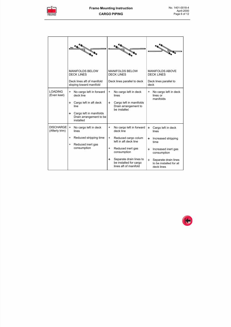
7/16/2019 Pompe Framo
http://slidepdf.com/reader/full/pompe-framo 152/175
Framo Mounting Instruction
CARGO PIPING
No. 1401-0018-4 April-2000
Page 6 of 12
MANIFOLDS BELOWDECK LINES
Deck lines aft of manifoldsloping toward manifold
MANIFOLDS BELOWDECK LINES
Deck lines parallel to deck
MANIFOLDS ABOVEDECK LINES
Deck lines parallel todeck
LOADING(Even keel)
+ No cargo left in forward
deck line
÷÷÷÷ Cargo left in aft deckline
÷÷÷÷ Cargo left in manifoldsDrain arrangement to be
installed
+ No cargo left in deck
lines
÷÷÷÷ Cargo left in manifoldsDrain arrangement tobe installed
+ No cargo left in deck
lines or manifolds
DISCHARGE(Afterly trim)
+ No cargo left in decklines
+ Reduced stripping time
+ Reduced inert gasconsumption
+ No cargo left in forwarddeck line
+ Reduced cargo columleft in aft deck line
+ Reduced inert gasconsumption
÷÷÷÷ Separate drain lines to
be installed for cargolines aft of manifold
÷÷÷÷ Cargo left in decklines
÷÷÷÷ Increased strippingtime
÷÷÷÷ Increased inert gasconsumption
÷÷÷÷ Separate drain linesto be installed for alldeck lines
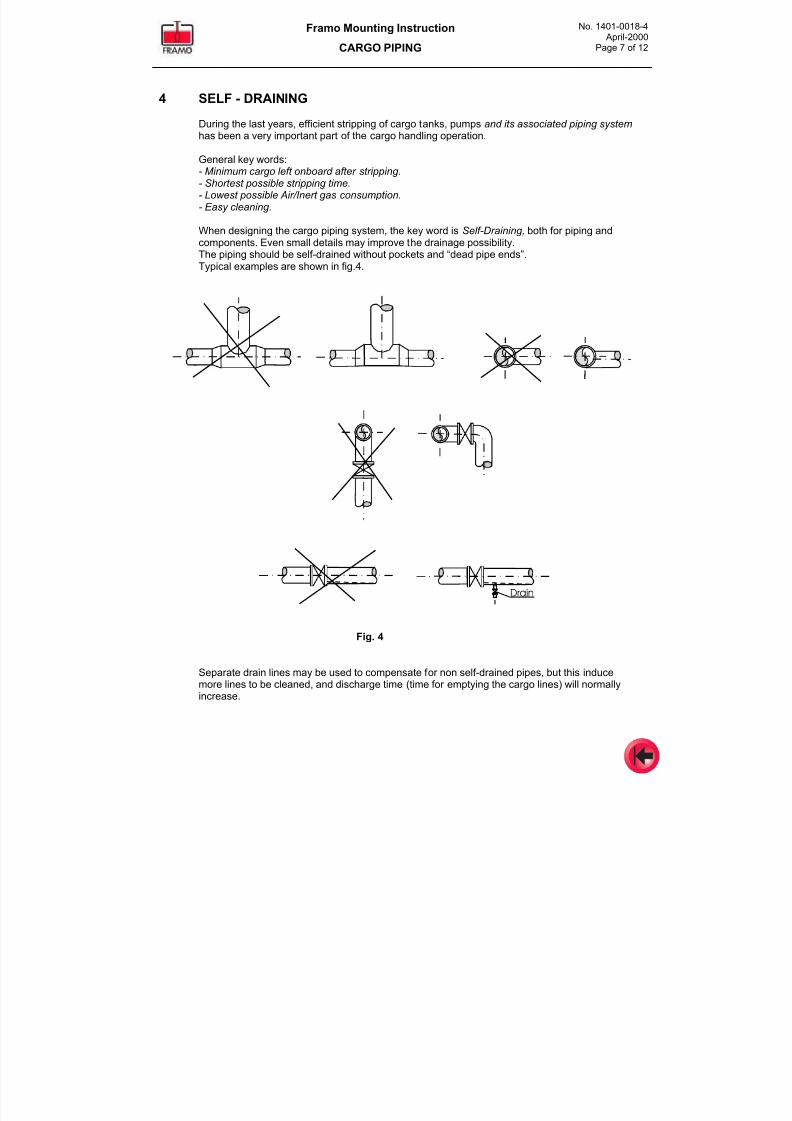
7/16/2019 Pompe Framo
http://slidepdf.com/reader/full/pompe-framo 153/175
Framo Mounting Instruction
CARGO PIPING
No. 1401-0018-4 April-2000
Page 7 of 12
4 SELF - DRAINING
During the last years, efficient stripping of cargo tanks, pumps and its associated piping system
has been a very important part of the cargo handling operation.
General key words:- Minimum cargo left onboard after stripping.- Shortest possible stripping time.- Lowest possible Air/Inert gas consumption.- Easy cleaning.
When designing the cargo piping system, the key word is Self-Draining, both for piping andcomponents. Even small details may improve the drainage possibility.The piping should be self-drained without pockets and “dead pipe ends”.Typical examples are shown in fig.4.
Drain
Fig. 4
Separate drain lines may be used to compensate for non self-drained pipes, but this inducemore lines to be cleaned, and discharge time (time for emptying the cargo lines) will normally
increase.
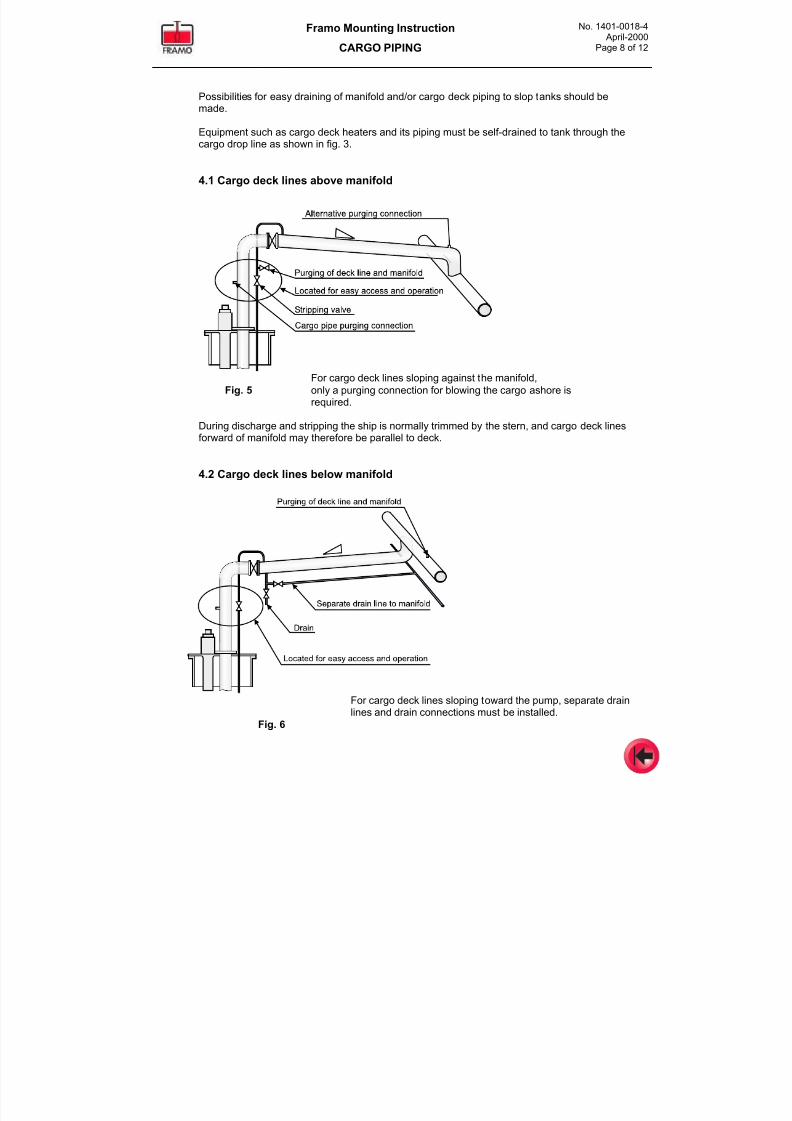
7/16/2019 Pompe Framo
http://slidepdf.com/reader/full/pompe-framo 154/175
Framo Mounting Instruction
CARGO PIPING
No. 1401-0018-4 April-2000
Page 8 of 12
Possibilities for easy draining of manifold and/or cargo deck piping to slop tanks should bemade.
Equipment such as cargo deck heaters and its piping must be self-drained to tank through thecargo drop line as shown in fig. 3.
4.1 Cargo deck lines above manifold
For cargo deck lines sloping against the manifold,
Fig. 5 only a purging connection for blowing the cargo ashore isrequired.
During discharge and stripping the ship is normally trimmed by the stern, and cargo deck linesforward of manifold may therefore be parallel to deck.
4.2 Cargo deck lines below manifold
For cargo deck lines sloping toward the pump, separate drainlines and drain connections must be installed.
Fig. 6
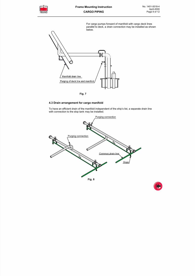
7/16/2019 Pompe Framo
http://slidepdf.com/reader/full/pompe-framo 155/175
Framo Mounting Instruction
CARGO PIPING
No. 1401-0018-4 April-2000
Page 9 of 12
For cargo pumps forward of manifold with cargo deck linesparallel to deck, a drain connection may be installed as shownbelow.
Fig. 7
4.3 Drain arrangement for cargo manifold
To have an efficient drain of the manifold independent of the ship’s list, a separate drain linewith connection to the slop tank may be installed.
Purging connection
Common drain line
Drain
Purging connection
Fig. 8
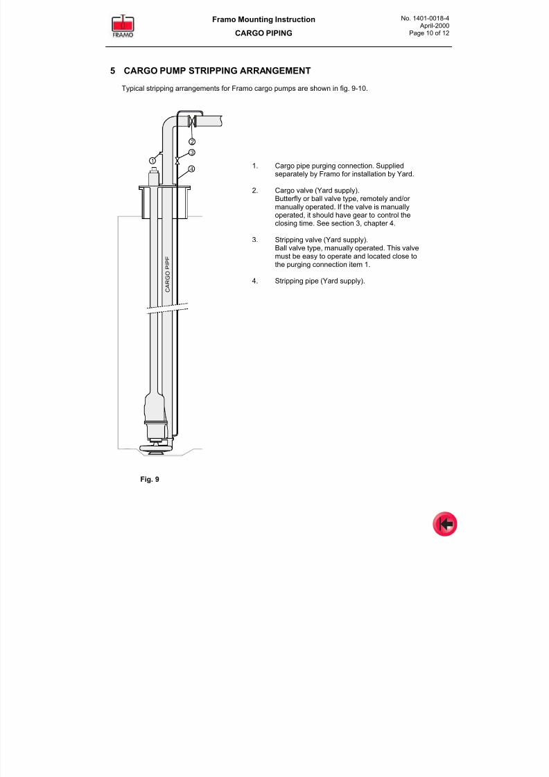
7/16/2019 Pompe Framo
http://slidepdf.com/reader/full/pompe-framo 156/175
Framo Mounting Instruction
CARGO PIPING
No. 1401-0018-4 April-2000
Page 10 of 12
5 CARGO PUMP STRIPPING ARRANGEMENT
Typical stripping arrangements for Framo cargo pumps are shown in fig. 9-10.
1. Cargo pipe purging connection. Suppliedseparately by Framo for installation by Yard.
2. Cargo valve (Yard supply).Butterfly or ball valve type, remotely and/or manually operated. If the valve is manuallyoperated, it should have gear to control theclosing time. See section 3, chapter 4.
3. Stripping valve (Yard supply).Ball valve type, manually operated. This valvemust be easy to operate and located close tothe purging connection item 1.
4. Stripping pipe (Yard supply).
2
3
4
1
C A
R G O
P I P E
Fig. 9
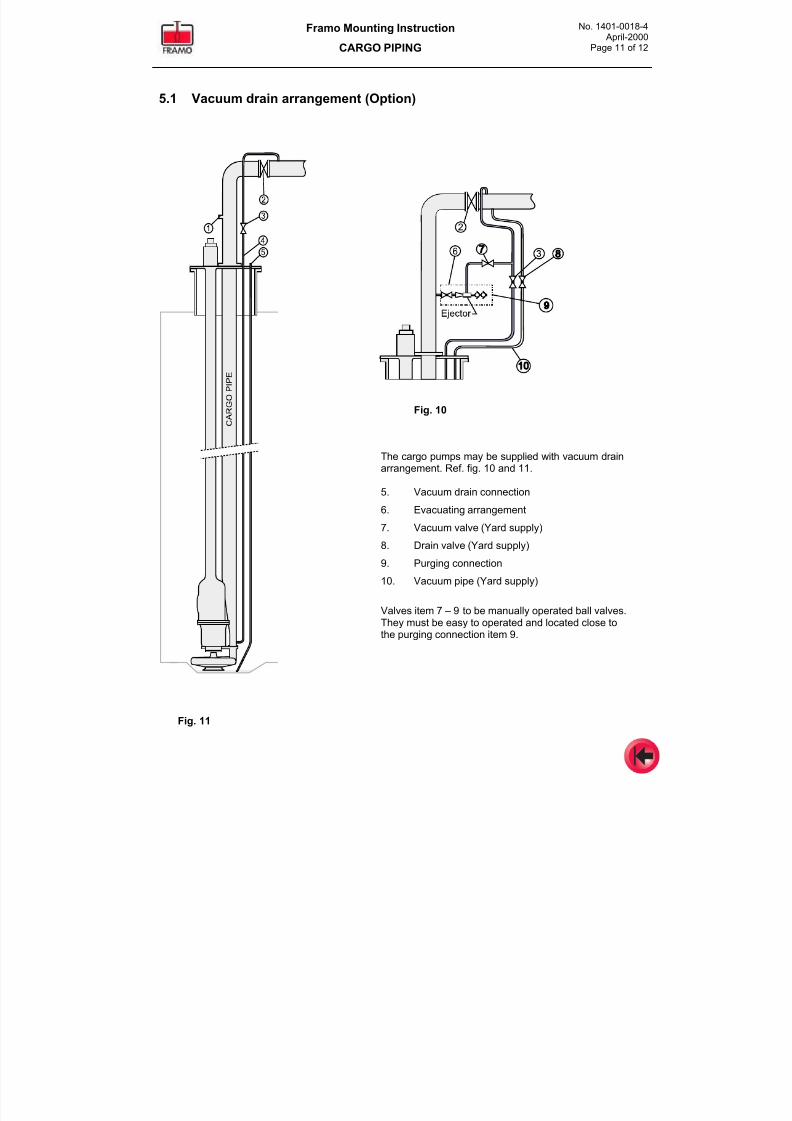
7/16/2019 Pompe Framo
http://slidepdf.com/reader/full/pompe-framo 157/175
Framo Mounting Instruction
CARGO PIPING
No. 1401-0018-4 April-2000
Page 11 of 12
5.1 Vacuum drain arrangement (Option)
Fig. 10
The cargo pumps may be supplied with vacuum drainarrangement. Ref. fig. 10 and 11.
5. Vacuum drain connection
6. Evacuating arrangement
7. Vacuum valve (Yard supply)
8. Drain valve (Yard supply)
9. Purging connection
10. Vacuum pipe (Yard supply)
Valves item 7 – 9 to be manually operated ball valves.They must be easy to operated and located close tothe purging connection item 9.
Fig. 11
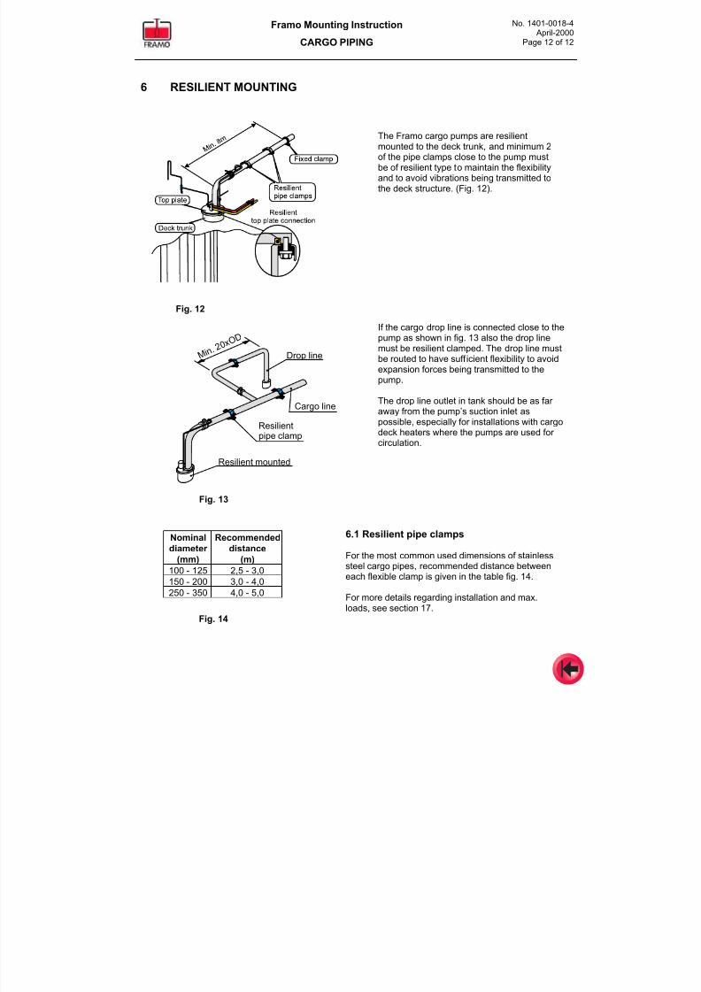
7/16/2019 Pompe Framo
http://slidepdf.com/reader/full/pompe-framo 158/175
Framo Mounting Instruction
CARGO PIPING
No. 1401-0018-4 April-2000
Page 12 of 12
6 RESILIENT MOUNTING
Fig. 12
Fig. 13
6.1 Resilient pipe clamps
For the most common used dimensions of stainlesssteel cargo pipes, recommended distance betweeneach flexible clamp is given in the table fig. 14.
For more details regarding installation and max.loads, see section 17.
Fig. 14
Resilientpipe clamp
Cargo line
Drop line
Resilient mounted
M i n. 2 0
x O D
Nominal
diameter
(mm)
Recommended
distance
(m)
100 - 125 2,5 - 3,0
150 - 200 3,0 - 4,0
250 - 350 4,0 - 5,0
The Framo cargo pumps are resilientmounted to the deck trunk, and minimum 2of the pipe clamps close to the pump mustbe of resilient type to maintain the flexibilityand to avoid vibrations being transmitted tothe deck structure. (Fig. 12).
If the cargo drop line is connected close to thepump as shown in fig. 13 also the drop linemust be resilient clamped. The drop line mustbe routed to have sufficient flexibility to avoid
expansion forces being transmitted to thepump.
The drop line outlet in tank should be as far away from the pump’s suction inlet aspossible, especially for installations with cargodeck heaters where the pumps are used for circulation.
7/16/2019 Pompe Framo
http://slidepdf.com/reader/full/pompe-framo 159/175
Framo
Mounting Instruction
Hydraulic oils - Oil filling
Pressure testing - Flushing
No. 1401-0019-4
Rev.C Dec-2002
CONTENTS
1 Selection of hydraulic oil
2 Cleanliness requirements
3 Leakage- and pressure testing of
piping system
3.1 Leakage testing
3.2 Safety3.3 Pressure testing with hydraulic oil
4 Initial oil filling
4.1 Oil filling before pressure testing
4.2 Oil filling before flushing
5 Flushing
5.1 Flushing procedure
6 Oil filling of components,
circulation and venting
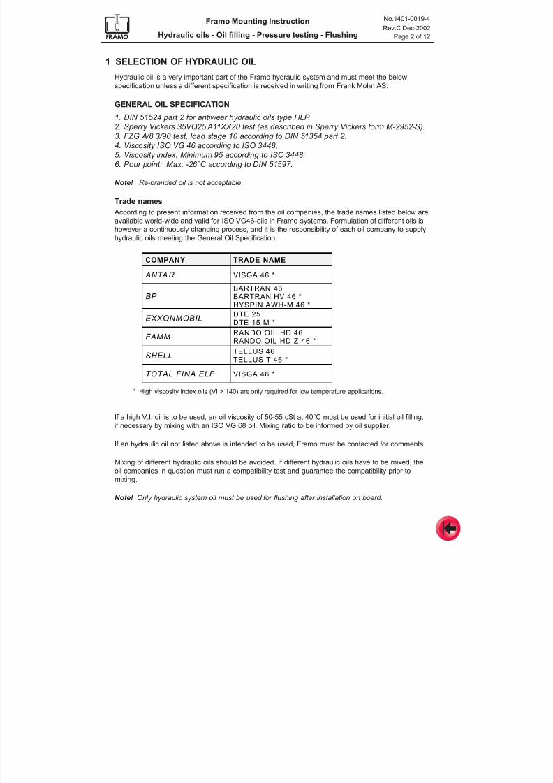
7/16/2019 Pompe Framo
http://slidepdf.com/reader/full/pompe-framo 160/175
Framo Mounting Instruction
Hydraulic oils - Oil filling - Pressure testing - Flushing
No.1401-0019-4
Rev.C Dec-2002
Page 2 of 12
1 SELECTION OF HYDRAULIC OIL
Hydraulic oil is a very important part of the Framo hydraulic system and must meet the below
specification unless a different specification is received in writing from Frank Mohn AS.
GENERAL OIL SPECIFICATION
1. DIN 51524 part 2 for antiwear hydraulic oils type HLP.
2. Sperry Vickers 35VQ25 A11XX20 test (as described in Sperry Vickers form M-2952-S).
3. FZG A/8,3/90 test, load stage 10 according to DIN 51354 part 2.
4. Viscosity ISO VG 46 according to ISO 3448.
5. Viscosity index. Minimum 95 according to ISO 3448.
6. Pour point: Max. -26°C according to DIN 51597.
Note! Re-branded oil is not acceptable.
Trade names
According to present information received from the oil companies, the trade names listed below are
available world-wide and valid for ISO VG46-oils in Framo systems. Formulation of different oils is
however a continuously changing process, and it is the responsibility of each oil company to supply
hydraulic oils meeting the General Oil Specification.
COMPANY TRADE NAME
ANTAR VISGA 46 *
BP BARTRAN 46BARTRAN HV 46 *HYSPIN AWH-M 46 *
EXXONMOBILDTE 25DTE 15 M *
FAMM RANDO OIL HD 46 RANDO OIL HD Z 46 *
SHELLTELLUS 46TELLUS T 46 *
TOTAL FINA ELF VISGA 46 *
* High viscosity index oils (VI > 140) are only required for low temperature applications.
If a high V.I. oil is to be used, an oil viscosity of 50-55 cSt at 40°C must be used for initial oil filling,
if necessary by mixing with an ISO VG 68 oil. Mixing ratio to be informed by oil supplier.
If an hydraulic oil not listed above is intended to be used, Framo must be contacted for comments.
Mixing of different hydraulic oils should be avoided. If different hydraulic oils have to be mixed, the
oil companies in question must run a compatibility test and guarantee the compatibility prior to
mixing.
Note! Only hydraulic system oil must be used for flushing after installation on board.
7/16/2019 Pompe Framo
http://slidepdf.com/reader/full/pompe-framo 161/175
Framo Mounting Instruction
Hydraulic oils - Oil filling - Pressure testing - Flushing
No.1401-0019-4
Rev.C Dec-2002
Page 3 of 12
2 CLEANLINESS REQUIREMENT
High pressure hydraulic pumps, motors and control valves have close tolerances and require clean
hydraulic oil to obtain reliability, good performance and long lifetime.
Contaminated oil will not provide satisfying lubrication and is a leading contributor to reduced
efficiency, excessive down time and increased maintenance costs.
There are three types of possible contamination in hydraulic systems:
- Solid particles Increased wear, reduced oil- and component life time, sticking valves,
unexpected system shut downs.
- Water Reduced lubrication, generating of metal particles to the
system, corrosion, reduced life time for oil and components.
- Air Pressure shocks and serious damage to hydraulic pumps, motors,
piping and other components, loss of oil and oil pollution.
The contamination may enter the system:
- During production and assembling of the system.
- During hydraulic oil filling. (New oil from supplier, refined and blended under “clean” conditions
is not clean).
- Together with the atmospheric air through air venting on the hydraulic tanks.
- By wear and tear generated within the system.
- During service.
To prevent contamination, it is important to maintain a high standard of cleanliness at all
times.
- Keep pipes and components clean and protected during the whole production- and assembling
period.
- The hydraulic oil must always be filtered by using the Framo hydraulic oil transfer unit when oil
is filled into the system from the storage tank.
- Oil filling must be done without mixing air into the oil during oil filling. It is very time-consuming
to get rid of air when it is mixed into the hydraulic oil.
- Hydraulic tanks must be vented indoor and if possible through air filters.- Wear and tear to be prevented by checking the hydraulic oil quality and cleanliness regularly,
and by replacing filter elements when necessary.
- Keep all parts clean during service and assembling. Refill with clean oil, vent and flush carefully
after assembling.
Cleanliness level:
The required cleanliness level is based upon ISO Solid Contaminant Code ISO 4406. The code
was revised during 1999 and are now referring to 3 sizes of particles, 4 - 6 - and 14 micron(c).
(Previous code referred to 5 - and 15 micron).
A typical result according to the revised code will be 18/16/12.Framo will only use the two last digits referring to 6- and 14 micron(c).

7/16/2019 Pompe Framo
http://slidepdf.com/reader/full/pompe-framo 162/175
Framo Mounting Instruction
Hydraulic oils - Oil filling - Pressure testing - Flushing
No.1401-0019-4
Rev.C Dec-2002
Page 4 of 12
The highest level of particles accepted in Framo systems is code 16/12.
Recommended cleanliness level during circulation and flushing is code 15/11 or better.
When reporting a particle count, it must be reported how the particle counting has been carried out:
- According to previous ISO 4406.- According to revised ISO 4406 (1999).
- By optical microscope.
Water content
The water content must be below 300 PPM (0.03 %).
3 LEAKAGE AND PRESSURE TESTING OF PIPING SYSTEM
The hydraulic system must be pressure tested to ensure that it is correctly mounted and not
leaking.
It is recommended to carry out a leakage test of the piping system with clean nitrogen gas at low
pressure before oil filling in order to locate possible leakages in the system without causing oil spill.
For final pressure testing with hydraulic oil, Framo requires the following minimum test pressures:
- Pressure lines: According to the classification society requirement
or at least system pressure + 70 bar.
- Return lines: 11 bar
The Framo commissioning engineer must be informed in due time before pressure testing.
Note! Framo equipment is pressure tested in the factory before shipment and must be
bypassed during testing.
Code
Number of particlesin 1 ml
Particle size acc.to previous code
Particle size acc.to 1999 revision
320 –640 5 micron 6 micron (c)16
12 20 – 40 15 micron 14 micron (c)
160 – 320 5 micron 6 micron (c)15
11 10 -20 15 micron 14 micron (c)
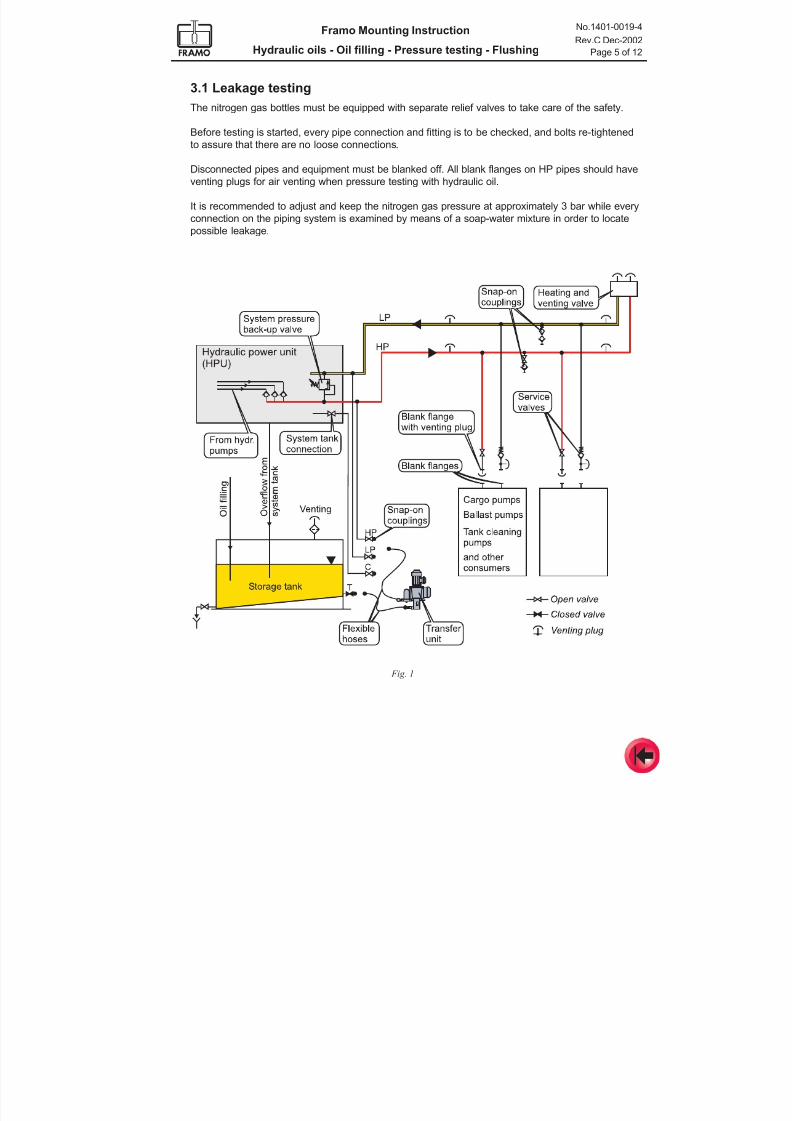
7/16/2019 Pompe Framo
http://slidepdf.com/reader/full/pompe-framo 163/175
Framo Mounting Instruction
Hydraulic oils - Oil filling - Pressure testing - Flushing
No.1401-0019-4
Rev.C Dec-2002
Page 5 of 12
3.1 Leakage testing
The nitrogen gas bottles must be equipped with separate relief valves to take care of the safety.
Before testing is started, every pipe connection and fitting is to be checked, and bolts re-tightened
to assure that there are no loose connections.
Disconnected pipes and equipment must be blanked off. All blank flanges on HP pipes should have
venting plugs for air venting when pressure testing with hydraulic oil.
It is recommended to adjust and keep the nitrogen gas pressure at approximately 3 bar while every
connection on the piping system is examined by means of a soap-water mixture in order to locate
possible leakage.
Fig. 1
7/16/2019 Pompe Framo
http://slidepdf.com/reader/full/pompe-framo 164/175
Framo Mounting Instruction
Hydraulic oils - Oil filling - Pressure testing - Flushing
No.1401-0019-4
Rev.C Dec-2002
Page 6 of 12
3.3 Pressure testing with hydraulic oil
Hydraulic pipes must be pressure tested with hydraulic oil.
Water or other fluids must never be used for pressure testing.
For pressure testing of the pressure lines, a special and cleanpressure testing pump must be used.
Note! The hydraulic power unit must not be used for pressure testing.
3.2 Safety
The hydraulic piping system is under very high pressure during testing.
Every possible action must be taken by the Yard in order to avoid damage both to man and
material.
Note! Before pressure testing is started every person not participating in the pressure
testing itself should be evacuated from exposed areas.
All access to the ship to be marked with signs, for example as shown below.
To have an overview of the hydraulic system there should be one person in charge for the pressure
testing. One person to be looking after the system in the power pack room, one in the pump room
and others on strategic places along the piping system. They must have communication equipment
enabling them to inform the person in charge if a leakage occurs.
Necessary equipment for collecting and removing of hydraulic oil must be available in case of
leakage.
Note! If hydraulic oil is leaking from the piping system during testing, the test pressure
must be set to zero. Leaking oil must be collected immediately and exposed area
cleaned.
The hydraulic oil must be drained out before any repairs are made on the piping system.
Hydraulic oil is slightly toxic, but will not cause bodily harm during normal use according to oil
companies information. However, be aware of that:
- Long lasting contact with the skin may cause skin irritation. Cover the skin or use protecting
cream when working with hydraulic oil.
- Oil into the eyes is normally not dangerous, but painful. Rinse the eye with fresh water for at
least 15 minutes.
- High concentrations of oil mist can irritate the respiratory organs.
7/16/2019 Pompe Framo
http://slidepdf.com/reader/full/pompe-framo 165/175
Framo Mounting Instruction
Hydraulic oils - Oil filling - Pressure testing - Flushing
No.1401-0019-4
Rev.C Dec-2002
Page 7 of 12
For pressure testing of the return lines, the hydraulic oil transfer unit can be used.
Oil must not be filled into the system before the Framo commissioning engineer has inspected and
accepted the cleanliness of the piping system and the associated system- and storage tanks.
If the hydraulic oil cooler and/or main filter box have been supplied separated from the HPU, (for closed systems only) the return line in-between must be checked very carefully before oil filling.
Initial oil filling must be carried out according to chapter 4 and in co-operation with the
Framo commissioning engineer.
It is recommended only to fill oil into the hydraulic pressure lines and start with pressure testing of
these lines. If leakages occur during the test, the oil may simply be transferred to the return side
before repair, by using the hydraulic transfer unit.
Before oil filling, check that:
- All HP service valves (ball valves) are in open position and blanked off in the open end.
- All ball valves on the snap-on coupling stations are in open position, ref. fig.1.
- The system back-up valve is closed in order to reduce the leakage over the valve to a minimum.
For pressures above 315 bar, a small leakage is normal.
- The heating and venting valve is closed. For pilot operated heating and venting valve, HP
service valve to be closed. For test pressures higher than 350 bar, HP service valve to be open
and blanked off in the open end.
After oil filling according to chapter 4, item 4.1, and proper air venting:
- Start the pressure testing pump and adjust the pressure in small steps up to approximately 70
bar. After the pressure is stabilised, hold this pressure while the complete piping system is
checked for leakage.
- Leakage control must be made by visual inspection and by monitoring irregular pressure drops.
Note that normal internal leakage in some hydraulic components might cause a certain pressure
drop during the inspection period.
- The visual inspection of the piping system should be carried out in two steps. First a quick
overview of the system to ensure that there is no major leakage, then every connection has to
be checked for leakage.
- Continue to raise the test pressure in steps up to approximately 150 bar, and check for leakage
as described above.
- Finally, the test pressure is to be adjusted in steps up to max. pressure according to theclassification society requirement or at least system pressure + 70 bar for the pressure line
(ref. page 4). Hold this pressure until the complete piping system is examined for leakage
(minimum 10 minutes or according to the classification society requirement).
When pressure testing of pressure lines is finished, continue to fill the return lines according to
item 4.1. Pressure test the return lines (ref. page 4).
7/16/2019 Pompe Framo
http://slidepdf.com/reader/full/pompe-framo 166/175
Framo Mounting Instruction
Hydraulic oils - Oil filling - Pressure testing - Flushing
No.1401-0019-4
Rev.C Dec-2002
Page 8 of 12
4 INITIAL OIL FILLING
Oil must not be filled into the system before the Framo commissioning engineer has inspected and
accepted the cleanliness of the piping system and the associated system- and storage tanks.
Initial oil filling must be carried out in co-operation with Framo commissioning engineer.
Necessary time for oil filling and venting depends on the system size, but in spite of limited time
schedule, we must emphasise the necessity of using the time needed to fill oil and get air out of the
system by proper venting.
The oil must be filled slowly into the lowest possible connections, making it possible to fill up the
pipings gradually while the air can escape through the open venting connections on the highest
points. It is very time consuming to get rid of air when it is mixed into the hydraulic oil, and mixing
must therefore be avoided.
If possible, the ship should have aft trim if the power unit is located aft, and forward trim if it is
located forward during oil filling and venting.
Venting must be done from all the high points in components and system.
If deck machinery is connected to the system, these are normally the highest points.
Only the hydraulic oil transfer unit should be used for oil filling of the system.
Capacity is given in Technical Data.
4.1 Oil filling before pressure testing
- Fill up the storage tank.- Prepare for pressure testing according to chapter 3.
- Open venting connections on the pressure side highest points.
- Drain off a small quantity of oil from the storage tank for visual check.
- Connect the transfer unit flexible hoses. Suction to T and supply to HP (ref. fig. 1), and
open the valves for oil filling into the HP line.
- Vent the hydraulic oil transfer unit, and check direction of rotation.
- Start the hydraulic oil transfer unit and fill oil into the high pressure line.
- Vent all pressure branch lines when the main pressure line is filled.
- When all the pressure lines are completely filled and vented, stop the transfer pump.
- Let possible air settle for at least 12 hours, then start pump for refilling and venting.
- When all air seems to be out, stop pump and disconnect flexible hoses.
Pressure test the pressure lines according to item 3.3.
When pressure lines are tested, start oil filling into the return lines.
- Open all the venting connections on the return side highest points.
- Connect the transfer unit flexible hoses. Suction to T and supply to LP (ref. fig. 1).
- Vent all return branch lines when the main return line is filled.
- When all the return lines are completely filled and vented, stop the transfer pump.
- Let possible air settle for at least 12 hours, then start pump for refilling and venting.
- When all air seems to be out, stop pump and disconnect flexible hoses.
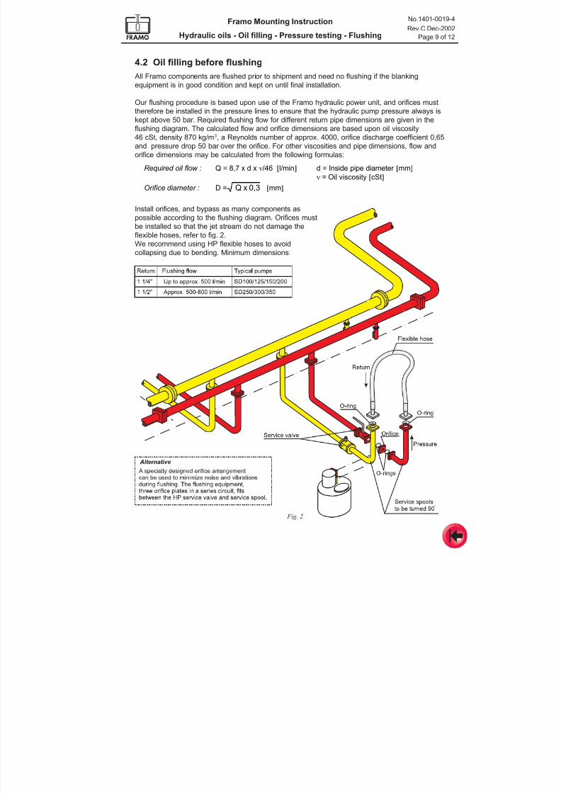
7/16/2019 Pompe Framo
http://slidepdf.com/reader/full/pompe-framo 167/175
Framo Mounting Instruction
Hydraulic oils - Oil filling - Pressure testing - Flushing
No.1401-0019-4
Rev.C Dec-2002
Page 9 of 12
4.2 Oil filling before flushing
All Framo components are flushed prior to shipment and need no flushing if the blanking
equipment is in good condition and kept on until final installation.
Our flushing procedure is based upon use of the Framo hydraulic power unit, and orifices must
therefore be installed in the pressure lines to ensure that the hydraulic pump pressure always is
kept above 50 bar. Required flushing flow for different return pipe dimensions are given in the
flushing diagram. The calculated flow and orifice dimensions are based upon oil viscosity
46 cSt, density 870 kg/m3, a Reynolds number of approx. 4000, orifice discharge coefficient 0,65
and pressure drop 50 bar over the orifice. For other viscosities and pipe dimensions, flow and
orifice dimensions may be calculated from the following formulas:
Fig. 2
Install orifices, and bypass as many components as
possible according to the flushing diagram. Orifices must
be installed so that the jet stream do not damage the
flexible hoses, refer to fig. 2.
We recommend using HP flexible hoses to avoid
collapsing due to bending. Minimum dimensions:
Required oil flow : Q = 8,7 x d x n/46 [l/min] d = Inside pipe diameter [mm]
n = Oil viscosity [cSt]
Orifice diameter : D = 0,3xQ [mm]
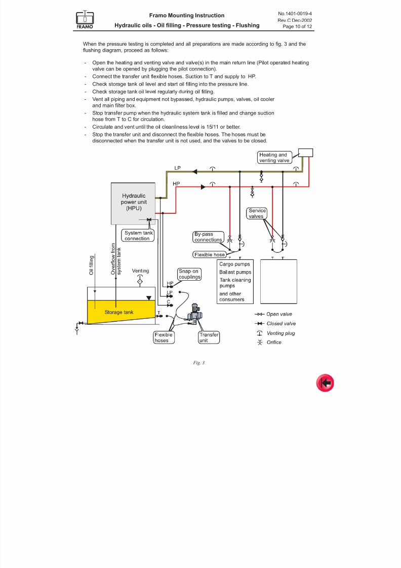
7/16/2019 Pompe Framo
http://slidepdf.com/reader/full/pompe-framo 168/175
Framo Mounting Instruction
Hydraulic oils - Oil filling - Pressure testing - Flushing
No.1401-0019-4
Rev.C Dec-2002
Page 10 of 12
When the pressure testing is completed and all preparations are made according to fig. 3 and the
flushing diagram, proceed as follows:
- Open the heating and venting valve and valve(s) in the main return line (Pilot operated heating
valve can be opened by plugging the pilot connection).- Connect the transfer unit flexible hoses. Suction to T and supply to HP.
- Check storage tank oil level and start oil filling into the pressure line.
- Check storage tank oil level regularly during oil filling.
- Vent all piping and equipment not bypassed, hydraulic pumps, valves, oil cooler
and main filter box.
- Stop transfer pump when the hydraulic system tank is filled and change suction
hose from T to C for circulation.
- Circulate and vent until the oil cleanliness level is 15/11 or better.
- Stop the transfer unit and disconnect the flexible hoses. The hoses must be
disconnected when the transfer unit is not used, and the valves to be closed.
Fig. 3
7/16/2019 Pompe Framo
http://slidepdf.com/reader/full/pompe-framo 169/175
Framo Mounting Instruction
Hydraulic oils - Oil filling - Pressure testing - Flushing
No.1401-0019-4
Rev.C Dec-2002
Page 11 of 12
5.1 Flushing procedure
When all preparations have been made according to item 4.2 and initial start-up of hydraulic power
packs are finished, follow the procedure given below. System pressure to be max. 70 bar.
Main lines
- Start one power pack and run at system pressure of max. 70 bar.
- Open the heating valve (Pilot operated valve can be opened by plugging the pilot connection).
- Run for approximately 5 minutes and take oil sample.
- Stop power pack.
- If cleanliness level is above 16/12, start circulation with jockey pump (for open systems) or
feed pump (for closed systems).
- When cleanliness level is 15/11 or better, start necessary number of power packs for flushing of
main return line. System pressure max. 70 bar. Manually operated heating valve can be kept
open, but pilot operated heating to be turned off and HP service valve to be closed. Open
service valves to necessary number of branch lines to obtain sufficient oil flow.
- Check cleanliness level regularly. If level increases above 16/12, stop flushing and start
circulation to reduce number of particles.- Fill in the Flushing report included in the Framo Commissioning Protocol.
- Flush until cleanliness level 15/11 or better.
- Check flow and temperature according to flushing diagram.
5 FLUSHING
Flushing is the last and final cleaning procedure in order to remove particles that has entered the
system during installation, and to bring the cleanliness of the system oil up to an acceptable level.
All Framo components are flushed prior to shipment and need no flushing if the blanking equipmentis in good condition and kept on until final installation. Use of the Framo hydraulic power unit for
flushing has proven to be the most efficient, time saving and practical procedure to avoid
unnecessary dismantling, oil spillage and possible entrance of contamination during assembling.
It is absolutely necessary that our procedure is followed very carefully if the Framo power
unit is used for flushing. Hydraulic pumps must not run with pressure below 50 bar.
Before starting the main hydraulic pumps for flushing, the hydraulic oil in the system tank must have
cleanliness level 15/11 or better.
An oil sampling procedure is included in the Framo Service Manual.
Note! Initial oil filling and start-up of the system has to be done by the Framo service engineer.
The oil flow must be turbulent in order to remove particles from the inner surface of the pipes and
transport them to the filter. Necessary flushing capacities based upon inside pipe diameters and oil
temperatures are given in the flushing diagram.
Oil flow for each power pack is given in Technical Data for the installation.
Recommended average oil temperature during flushing is 50°C.
The flushing time depends on system size, cleanliness and piping material. Stainless steel pipes
require normally less time for flushing than mild steel pipes.
The following figures may be used as a rough estimate:
- Main lines, 1st sequence: Approx. 6 hours
- Branch lines (each): Approx. 2 hours
- Main lines, 2nd sequence: Approx. 4 hours
7/16/2019 Pompe Framo
http://slidepdf.com/reader/full/pompe-framo 170/175
Framo Mounting Instruction
Hydraulic oils - Oil filling - Pressure testing - Flushing
No.1401-0019-4
Rev.C Dec-2002
Page 12 of 12
6 OIL FILLING OF COMPONENTS, CIRCULATION AND VENTING
All by-passed components, cargo pumps etc. must be filled with oil and vented properly after
flushing to avoid air mixed into the system.
It is very important to get the air out of all components and hydraulic lines instead of having the
oil/air mixture back to hydraulic tank, hydraulic pumps etc.
Note! Oil filling has to be done slowly to let the air escape through the venting connections.
Air in the system is indicated by:
- Back flow to the hydraulic tank during stand still
- Great difference between tank level at low and high system pressure
- Foaming
- Discolorated oil
Please note that Framo is not responsible for damages caused by air in the hydraulic oil, or if the
system has been started without Framo commissioning engineer’s approval.
Branch lines
- Close the heating valve.
- Start necessary number of power packs for the arranged number of branch lines to be flushed
simultaneously.
- Open ball valve to the branch lines and follow the same procedure as for the main lines.- Continue until all branch lines are flushed to cleanliness level 15/11 or better.
Main lines, 2 nd sequence
- Start necessary numbers of power packs for flushing of main return line.
- Open the heating valve and ball valve to necessary number of branch lines to obtain sufficient oil
flow.
- Flush until cleanliness level 15/11 or better.
Pilot pipes and pipes with inside diameter less than 25 mmFor these pipes turbulent flow is not obtainable due to the high pressure drop. It is therefore required
that the pipes are purged with clean nitrogen.
Other methods like “Pigging” (special plugs blown through the pipe by using a special tool) may be
used, but the results depends very much upon pipe material, quality, welding and pipe lengths.
Please contact Frank Mohn Services AS if such methods are considered to be used.
Branch pipes for dry mounted pumps and thruster motors
See separate flushing diagram.
7/16/2019 Pompe Framo
http://slidepdf.com/reader/full/pompe-framo 171/175
Framo
Mounting Instruction
Commissioning - Testing
No. 1401-0020-4
Rev. Oct-2000
CONTENTS
1 General
2 Verification of design and installation procedures
3 Final Check-out and Start-up schedule
4 Final Check-out and Start-up
5 Testing
7/16/2019 Pompe Framo
http://slidepdf.com/reader/full/pompe-framo 172/175
No.1401-0020-4
Rev. Oct-2000
Page 2 of 5
Framo Mounting Instruction
COMMISSIONING - TESTING
1 GENERAL
The commissioning shall ensure that the delivered equipment, installation and its function are in
accordance with the Framo documentation, and to demonstrate the operational capabilities of the
system.The time consumption for commissioning depends on ship type and size, system size, and Yards
progress related to other equipment and parts of the ship which will effect the various activities
related to the Framo cargo pumping system. It is also related to a correct installation according to
Framo requirements.
In general the commissioning is divided in two sequences:
1. Verification of design and installation procedures, (normally not necessary for the 2nd and the
following ships in a series if the Yard personnel responsible for the installation are the same).
2. Final check-out and start-up
2 VERIFICATION OF DESIGN AND INSTALLATION PROCEDURES
The verification part should be a coordination meeting between Yard and Framo to ensure that the
engineering and the actual installation are carried out to both parties satisfaction.
This quality assurance meeting should be held at the Yard at an early stage of the installation. The
following personnel should participate:
From Yard : Outfitting and Design personnel. (It is very important that personnel responsible for
the actual installation on board are present during this meeting).
From Framo : Project manager (Technical dept.) and Project engineer (Service dept.)
Yard and Framo should appoint suitable time for this meeting, and the verification activity should
mainly be focused on:
- Handling and storage of Framo equipment.
- Review technical documentation.
- Location and installation of Framo equipment.
- Location and installation of Yard associated equipment.
- Hydraulic- and cargo piping installation.- Pre-inspection of installed equipment.
- Commissioning progress and schedule (to be worked out).
- Review the practical realization of the final check-out and start-up activities, requirements
for Yard assistance etc.
3 FINAL CHECK-OUT AND START-UP SCHEDULE
During check-out and start-up of the Framo Cargo Pumping System also other equipment on board
will be involved, such as auxiliary machinery and generators, cargo lines and tanks, cargo andballast valve systems etc.
Installation and commissioning of these systems must therefore be incorporated when planning the
various activities and time needed.
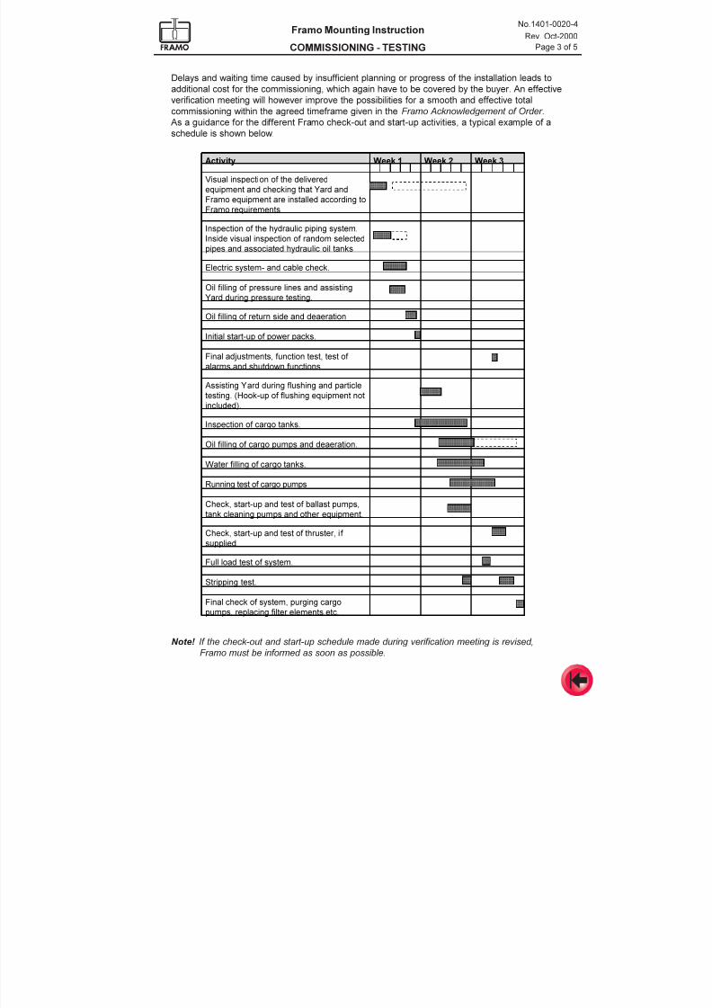
7/16/2019 Pompe Framo
http://slidepdf.com/reader/full/pompe-framo 173/175
No.1401-0020-4
Rev. Oct-2000
Page 3 of 5
Framo Mounting Instruction
COMMISSIONING - TESTING
Note! If the check-out and start-up schedule made during verification meeting is revised,
Framo must be informed as soon as possible.
$FWLYLW\ :HHN :HHN :HHNÃ Ã Ã Ã Ã Ã Ã Ã Ã Ã Ã Ã Ã Ã Ã Ã
9LVXDOLQVSHFWLRQRIWKHGHOLYHUHG
HTXLSPHQWDQGFKHFNLQJWKDW<DUGDQG
)UDPRHTXLSPHQWDUHLQVWDOOHGDFFRUGLQJWR
)UDPRUHTXLUHPHQWV
à à à Ã
,QVSHFWLRQRIWKHK\GUDXOLFSLSLQJV\VWHP
,QVLGHYLVXDOLQVSHFWLRQRIUDQGRPVHOHFWHG
SLSHVDQGDVVRFLDWHGK\GUDXOLFRLOWDQNV
à à à Ã
(OHFWULFV\VWHPDQGFDEOHFKHFN Ã Ã Ã Ã
2LOILOOLQJRISUHVVXUHOLQHVDQGDVVLVWLQJ
<DUGGXULQJSUHVVXUHWHVWLQJ
à à à Ã
2LOILOOLQJRIUHWXUQVLGHDQGGHDHUDWLRQ Ã Ã Ã Ã
,QLWLDOVWDUWXSRISRZHUSDFNV Ã Ã Ã Ã
)LQDODGMXVWPHQWVIXQFWLRQWHVWWHVWRI
DODUPVDQGVKXWGRZQIXQFWLRQVÃ
à à Ã
à à à Ã
$VVLVWLQJ<DUGGXULQJIOXVKLQJDQGSDUWLFOH
WHVWLQJ+RRNXSRIIOXVKLQJHTXLSPHQWQRW
LQFOXGHG
à à à Ã
,QVSHFWLRQRIFDUJRWDQNV Ã Ã Ã Ã
2LOILOOLQJRIFDUJRSXPSVDQGGHDHUDWLRQ Ã Ã Ã Ã
:DWHUILOOLQJRIFDUJRWDQNV Ã Ã Ã Ã
5XQQLQJWHVWRIFDUJRSXPSV Ã Ã Ã Ã
&KHFNVWDUWXSDQGWHVWRIEDOODVWSXPSV
WDQNFOHDQLQJSXPSVDQGRWKHUHTXLSPHQW
à à à Ã
&KHFNVWDUWXSDQGWHVWRIWKUXVWHULI
VXSSOLHG
à à à Ã
)XOOORDGWHVWRIV\VWHP Ã Ã Ã Ã
6WULSSLQJWHVW Ã Ã Ã Ã
)LQDOFKHFNRIV\VWHPSXUJLQJFDUJR
SXPSVUHSODFLQJILOWHUHOHPHQWVHWF
Delays and waiting time caused by insufficient planning or progress of the installation leads to
additional cost for the commissioning, which again have to be covered by the buyer. An effective
verification meeting will however improve the possibilities for a smooth and effective total
commissioning within the agreed timeframe given in the Framo Acknowledgement of Order .
As a guidance for the different Framo check-out and start-up activities, a typical example of aschedule is shown below.
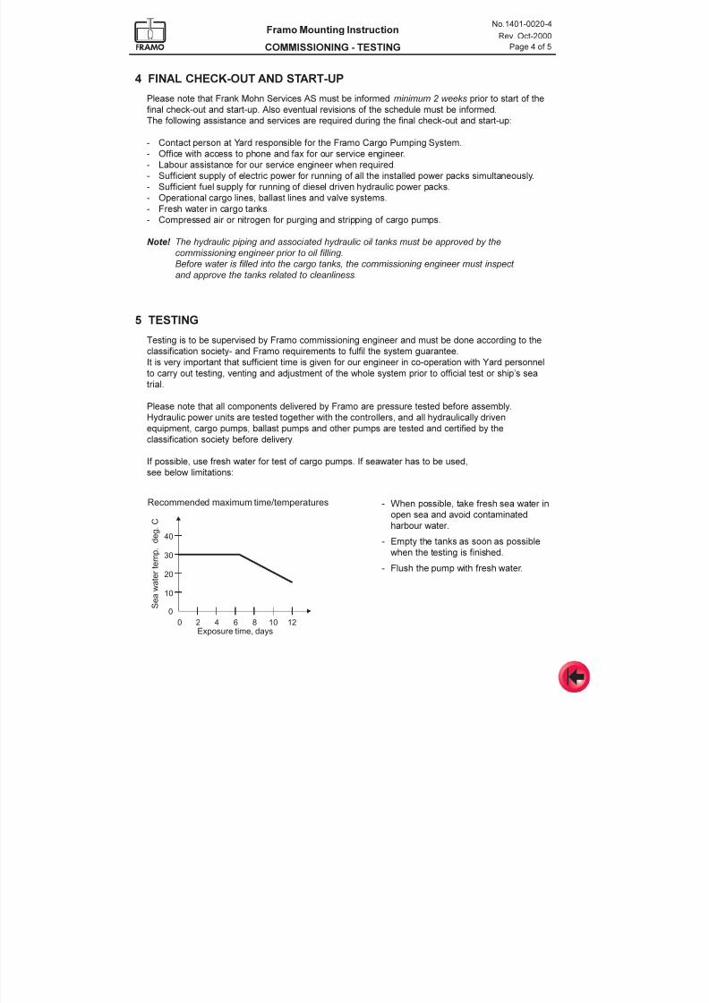
7/16/2019 Pompe Framo
http://slidepdf.com/reader/full/pompe-framo 174/175
No.1401-0020-4
Rev. Oct-2000
Page 4 of 5
Framo Mounting Instruction
COMMISSIONING - TESTING
4 FINAL CHECK-OUT AND START-UP
Please note that Frank Mohn Services AS must be informed minimum 2 weeks prior to start of the
final check-out and start-up. Also eventual revisions of the schedule must be informed.
The following assistance and services are required during the final check-out and start-up:
- Contact person at Yard responsible for the Framo Cargo Pumping System.
- Office with access to phone and fax for our service engineer.
- Labour assistance for our service engineer when required.
- Sufficient supply of electric power for running of all the installed power packs simultaneously.
- Sufficient fuel supply for running of diesel driven hydraulic power packs.
- Operational cargo lines, ballast lines and valve systems.
- Fresh water in cargo tanks.
- Compressed air or nitrogen for purging and stripping of cargo pumps.
Note! The hydraulic piping and associated hydraulic oil tanks must be approved by the
commissioning engineer prior to oil filling.
Before water is filled into the cargo tanks, the commissioning engineer must inspect
and approve the tanks related to cleanliness.
5 TESTING
Testing is to be supervised by Framo commissioning engineer and must be done according to the
classification society- and Framo requirements to fulfil the system guarantee.
It is very important that sufficient time is given for our engineer in co-operation with Yard personnel
to carry out testing, venting and adjustment of the whole system prior to official test or ships seatrial.
Please note that all components delivered by Framo are pressure tested before assembly.
Hydraulic power units are tested together with the controllers, and all hydraulically driven
equipment, cargo pumps, ballast pumps and other pumps are tested and certified by the
classification society before delivery.
If possible, use fresh water for test of cargo pumps. If seawater has to be used,
see below limitations:
- When possible, take fresh sea water in
open sea and avoid contaminated
harbour water.
- Empty the tanks as soon as possible
when the testing is finished.
- Flush the pump with fresh water.
0
0
10
20
30
40
2Exposure time, days
Recommended maximum time/temperatures
S e a w a
t e r
t e m p
. d e g
. C
4 6 8 10 12
7/16/2019 Pompe Framo
http://slidepdf.com/reader/full/pompe-framo 175/175
No.1401-0020-4
Rev. Oct-2000
Page 5 of 5
Framo Mounting Instruction
COMMISSIONING - TESTING
The following tests are required in order to ensure proper function of the system and to issue a
Framo Completion Certificate:
- Hydraulic piping to be pressure tested according to the classification society requirement.
Pressure piping must be tested with a minimum test pressure of System pressure + 70bar. A special (and clean) pressure testing pump has to be used.
Return piping with a minimum test pressure of 11 bar. The hydraulic oil transfer unit can be
used for this test.
- Particle- and water test of the hydraulic oil.
- Acceptance test of alarms and shut down functions.
- Running of Yard equipment connected to the Framo system to ensure that no pressure
shocks are transmitted to the system.
- Running of cargo pumps, ballast pumps and other pumps.
It is recommended to do a stripping test for each cargo pump according to
Marpol 73/78 Water test procedure.
If additional tests are required, test requirements and procedures have to be evaluated and
approved by Framo.