Residential New Construction Mechanical Systems Testing …...Residential New Construction...
41
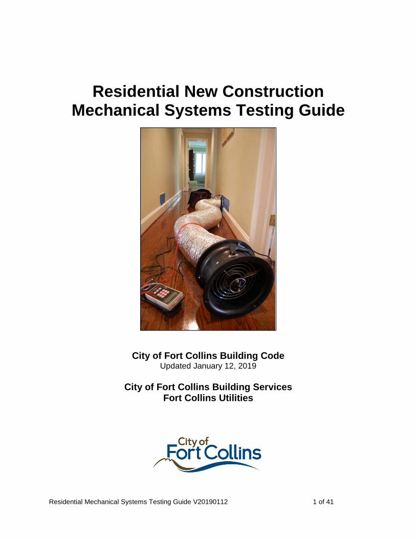
Residential Mechanical Systems Testing Guide V20190112 1 of 41 Residential New Construction Mechanical Systems Testing Guide City of Fort Collins Building Code Updated January 12, 2019 City of Fort Collins Building Services Fort Collins Utilities
Transcript of Residential New Construction Mechanical Systems Testing …...Residential New Construction...
Residential Mechanical Systems Testing Guide V20190112 1 of 41
Residential New Construction Mechanical Systems Testing Guide
City of Fort Collins Building Code Updated January 12, 2019
City of Fort Collins Building Services
Fort Collins Utilities

Residential Mechanical Systems Testing Guide V20190112 2 of 41
Contents
What This Guide Is . . . and Is Not .............................................................................................. 5
Acknowledgements ....................................................................................................................... 5
1.0 Code Performance Testing Requirements ............................................................................ 6
1.1 Heating, Cooling, Ventilation ............................................................................................................. 6
1.2 Combustion Safety .............................................................................................................................. 6
1.3 Submittal Form (single family & muli-family) .................................................................................. 7
1.4 Applicability ....................................................................................................................................... 7
2.0 General Information ............................................................................................................... 7
2.1 Test Equipment ................................................................................................................................... 7
2.2 Volumetric Flow ................................................................................................................................. 7
2.3 Documentation and Accountability .................................................................................................... 8
2.4 General Tips ........................................................................................................................................ 8
2.5 Quality Assurance ............................................................................................................................... 8
3.0 Local Exhaust (Spot Ventilation) Airflow ............................................................................ 8
3.1 Compliance requirements ................................................................................................................... 9
3.2 Test Equipment ................................................................................................................................... 9
3.3 Measuring Bath Fan Airflow .............................................................................................................. 9
3.4 Measuring Kitchen Hood Airflow .................................................................................................... 10
3.5 Measuring Kitchen Hood Makeup Air ............................................................................................. 11
4.0 Whole-Dwelling-Unit Ventilation Airflow .......................................................................... 12
4.1 Compliance Requirements ................................................................................................................ 12
4.2 Referenced Protocols ........................................................................................................................ 13
4.3 Test Equipment ................................................................................................................................. 14
4.4 Measuring Exhaust Airflow – Single Pickup .................................................................................... 14
4.5 Measuring Exhaust Airflow – Multi-Pickup ..................................................................................... 14
4.6 Measuring Supply Airflow – Delivered Through the Furnace Air Handler ..................................... 15
4.7 Measuring Supply Airflow – Independently Ducted ........................................................................ 16
4.8 Measuring Balanced Airflows .......................................................................................................... 16
5.0 Heating + Cooling Duct Leakage ......................................................................................... 17
5.1 Compliance Requirements ................................................................................................................ 17
5.2 Referenced Protocols ........................................................................................................................ 18
5.3 Test Equipment ................................................................................................................................. 18

Residential Mechanical Systems Testing Guide V20190112 3 of 41
5.4 Measuring Total Duct Leakage ......................................................................................................... 18
6.0 Air Handler Static Pressures ............................................................................................... 20
6.1 Test Equipment ................................................................................................................................. 20
6.2 Measuring Static Pressures ............................................................................................................... 20
7.0 Air Conditioner: Airflow Through Indoor Coil ................................................................. 21
7.1 Compliance Requirement ................................................................................................................. 21
7.2 Referenced Protocol .......................................................................................................................... 21
7.3 Test Equipment ................................................................................................................................. 21
7.4 Measuring Air Handler Cooling Airflow .......................................................................................... 22
8.0 Gas Furnace: Manifold Gas Pressure ................................................................................. 24
8.1 Compliance Requirement ................................................................................................................. 24
8.2 Referenced Protocol .......................................................................................................................... 24
8.3 Test Equipment ................................................................................................................................. 24
8.4 Target Manifold Pressure .................................................................................................................. 24
8.5 Measuring and Adjusting Manifold Pressure ................................................................................... 25
9.0 Gas Furnace: Temperature Rise ......................................................................................... 25
9.1 Compliance Requirement ................................................................................................................. 26
9.2 Referenced Protocol .......................................................................................................................... 26
9.3 Test Equipment ................................................................................................................................. 26
9.4 Measuring Temperature Rise ............................................................................................................ 26
10.0 Air Conditioner: Refrigerant Charge ............................................................................... 27
11.0 Room Air Flow .................................................................................................................... 27
12.0 Room Pressure Balance ...................................................................................................... 27
12.1 Compliance Requirement ............................................................................................................... 28
12.2 Referenced Protocol ........................................................................ Error! Bookmark not defined.
12.3 Test Equipment ............................................................................................................................... 28
12.4 Measuring Room Pressure Balance ................................................................................................ 28
13.0 Combustion Safety .............................................................................................................. 29
13.1 Compliance Requirement ............................................................................................................... 29
13.2 Referenced Protocol ........................................................................................................................ 29
13.3 Test Equipment ............................................................................................................................... 29
13.4 Worst-Case CAZ Depressurization Setup ...................................................................................... 30
13.5 Equipment Performance Under Worst-Case CAZ Depressurization .............................................. 31
14.0 System Controls .................................................................................................................. 32
14.1 Compliance Requirement ............................................................................................................... 32

Residential Mechanical Systems Testing Guide V20190112 4 of 41
14.2 Testing Controls .............................................................................................................................. 32
Appendix A: Testing Equipment Useful For Multiple Tests .................................................. 33
15.1 Manometer ...................................................................................................................................... 33
15.2 Air Flow Resistance Meter (Flow Box) .......................................................................................... 34
15.3 Low-Flow Passive Flow Capture Hood .......................................................................................... 35
15.4 Powered Flow Capture Hood .......................................................................................................... 36
15.5 Pitot Tube Anemometer .................................................................................................................. 37
15.6 Airflow Measurement Station (Flow Collar) .................................................................................. 39
15.7 Flow Bag ......................................................................................................................................... 39
Appendix B: Correcting Flow Data for Air Density ................................................................ 40
16.1 Indicated and Volumetric Flow ...................................................................................................... 40
16.2 Air Density Correction Factors (ADCF)......................................................................................... 40

Residential Mechanical Systems Testing Guide V20190112 5 of 41
What This Guide Is . . . and Is Not This document is intended to be a “Cliffs Notes” guide to help you successfully complete the City of Fort Collins code testing requirements and Residential Mechanical Systems Performance Report. The guide includes references to detailed testing protocols, lists allowed test equipment, specifies pass/fail limits and provides reminder/tips for each required test. It is intended to reinforce what is covered in the City’s “Residential Mechanical Systems Testing” training. This guide does not include all the details you need to know to correctly apply all the approved testing protocols or to successfully use all of the allowed testing equipment. For those details you must consult the actual protocols and/or the equipment manufacturers’ operating instructions. This guide is a working document that will be updated with additional information as more experience is gained with the code’s testing requirements. Users are encouraged to direct questions and provide suggestions for improvement to: Brad Smith, [email protected], 970-416-4321
Kim DeVoe, [email protected], 970-221-6749
Acknowledgements The information contained in this guide is compiled from many sources. Many people and organizations have contributed their expertise, directly or indirectly. At the risk of inadvertently missing someone, contributors include: • Residential Energy Services Network (RESNET) • Building Performance Institute (BPI) • The Energy Conservatory • Proctor Engineering Group • Iain Walker, Lawrence Berkeley National Lab • Don Stevens, Panasonic Home + Environment Company • Mike Missimer, Fort Collins Heating & Air • Nick Buike, Group14 Engineering • Robby Schwarz, EnergyLogic • Joe Nagan, Home Building Technology Services • Rob deKieffer, Boulder Design Alliance • John Krigger and Chris Dorsi, Saturn Resource Management
Residential Mechanical Systems Testing Guide V20190112 6 of 41
Design
Test
Build
Is it there?
Does it work?
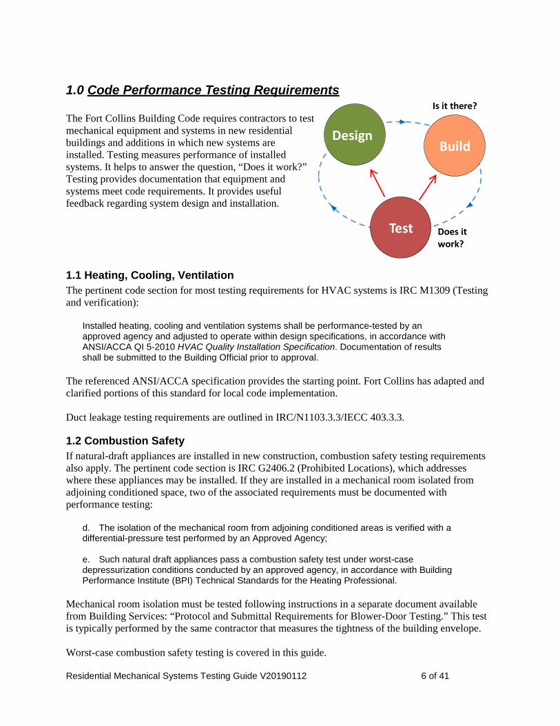
1.0 Code Performance Testing Requirements The Fort Collins Building Code requires contractors to test mechanical equipment and systems in new residential buildings and additions in which new systems are installed. Testing measures performance of installed systems. It helps to answer the question, “Does it work?” Testing provides documentation that equipment and systems meet code requirements. It provides useful feedback regarding system design and installation.
1.1 Heating, Cooling, Ventilation The pertinent code section for most testing requirements for HVAC systems is IRC M1309 (Testing and verification):
Installed heating, cooling and ventilation systems shall be performance-tested by an approved agency and adjusted to operate within design specifications, in accordance with ANSI/ACCA QI 5-2010 HVAC Quality Installation Specification. Documentation of results shall be submitted to the Building Official prior to approval.
The referenced ANSI/ACCA specification provides the starting point. Fort Collins has adapted and clarified portions of this standard for local code implementation. Duct leakage testing requirements are outlined in IRC/N1103.3.3/IECC 403.3.3.
1.2 Combustion Safety If natural-draft appliances are installed in new construction, combustion safety testing requirements also apply. The pertinent code section is IRC G2406.2 (Prohibited Locations), which addresses where these appliances may be installed. If they are installed in a mechanical room isolated from adjoining conditioned space, two of the associated requirements must be documented with performance testing:
d. The isolation of the mechanical room from adjoining conditioned areas is verified with a differential-pressure test performed by an Approved Agency; e. Such natural draft appliances pass a combustion safety test under worst-case depressurization conditions conducted by an approved agency, in accordance with Building Performance Institute (BPI) Technical Standards for the Heating Professional.
Mechanical room isolation must be tested following instructions in a separate document available from Building Services: “Protocol and Submittal Requirements for Blower-Door Testing.” This test is typically performed by the same contractor that measures the tightness of the building envelope. Worst-case combustion safety testing is covered in this guide.
Residential Mechanical Systems Testing Guide V20190112 7 of 41
1.3 Submittal Form Mechanical systems testing results must be submitted using the Residential Mechanical Systems Performance Report, available for download from the City of Fort Collins Building Services web site (www.fcgov.com/energycode). Use the most recent version; check the web site for updates. Sections on each test in this guide are cross-referenced to the companion section in the performance report. Multi-Family projects need only submit the Multifamily Residential Test & Balance form for each building and do not need to submit a separate Residential Mechanical Systems Performance Report for each unit tested although performing the testing on each unit is still required. The bottom line on the performance report is that performance of each measured system must “pass” by meeting a prescribed range, limit or threshold. These targets come from four sources:
(1) A fixed code requirement (Example: local exhaust minimum airflow rates); (2) A fixed testing requirement (Example: maximum room-to-core pressure drop); (3) Equipment manufacturer specifications (Example: furnace heat rise range); (4) The mechanical system design submitted as part of the building permit application (Example:
airflow across the AC evaporator coil). You must have this information at hand while doing the testing. All of the targets of types (3) and (4) should be available in the design submittal. You must provide the date for the design submittal in Section 1 of the performance report. The color code at the top of the first page of the performance report helps guide you through successful completion of the report.
1.4 Applicability To date, testing requirements and protocols have been developed for and apply in full to the most common systems installed in new Fort Collins residential construction: forced-air heating and cooling using gas-fired furnaces and split-system air conditioning sharing the furnace air handler and ductwork. For other system types, check with Building Services for testing requirements.
2.0 General Information
2.1 Test Equipment The description of each test includes a “Test Equipment” subsection. This outlines tools that are allowed and/or likely to be appropriate for the test. Most of this equipment is available from multiple manufacturers. Equipment required for measuring air handler airflow is only available from a single manufacturer, to the authors’ knowledge. Readers are encouraged to contact the authors if they know of other equipment that might serve the needs of the test. Information regarding equipment specific to only one type of required test is located in the section for that particular test. Information regarding equipment that can be used for several of the required tests is located in Appendix A.
2.2 Volumetric Flow For consistency, all airflow rates for both design and testing are based on volumetric flow at 5000’ elevation. Indicated airflow rates registered by the test equipment must generally be converted to volumetric flow by multiplying by a constant, referred to on the performance report as the “Air Density Correction Factor,” abbreviated ADCF. See Appendix B for information.

Residential Mechanical Systems Testing Guide V20190112 8 of 41
2.3 Documentation and Accountability Because many tests can be performed with a variety of testing tools, the performance report generally provides space to record only a subset of the data you must collect to determine whether a system passes or fails each test. You are strongly encouraged to keep a record of all intermediate data so that you can check your own work and, if asked by Building Services, will be able to answer questions about how you performed a test or calculated particular numbers. “Testing Notes” fields are provided in many sections. Use these to document anything unusual or that you think might be needed to help someone repeating the test in the future to understand what you did. Your initials in each section, and signature at the end of the performance report indicates you take accountability for the data contained in those sections. All submitted reports are public records electronically available through citydocs.fcgov.com.
2.4 General Tips • Engage your brain. Know why you’re measuring. Know what you’re measuring. Know the
general range of results you are expecting.
• “If all else fails, read the manual.”
• Calibrate your equipment, following the manufacturer’s schedule.
• Think about where you take a measurement. Will you get an accurate reading?
• Cross-check results with redundant measurements. Use more than one type of tool when practical.
• Accurate airflow measurement is challenging.
• If your test result is right at the edge of compliance, it would be wise to see if adjustments can be made to bring the performance further within the target range.
2.5 Quality Assurance You, the testing contractor, are the most important quality assurance link. It’s very important that you “sniff test” the data your tools are providing, before submitting them in your performance report. Are the numbers reasonable? Do they make sense? If not, why not? Building Services will spot-check testing results and hold testing agencies accountable for the numbers they turn in to document code compliance.
3.0 Local Exhaust (Spot Ventilation) Airflow See Section 2 on Residential Mechanical Systems Performance Report. Bath fans and vented kitchen hoods are classified as “local exhaust” or “spot ventilation.”
Residential Mechanical Systems Testing Guide V20190112 9 of 41
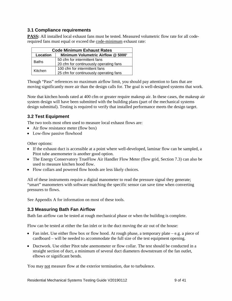
3.1 Compliance requirements PASS: All installed local exhaust fans must be tested. Measured volumetric flow rate for all code-required fans must equal or exceed the code-minimum exhaust rate:
Though “Pass” references no maximum airflow limit, you should pay attention to fans that are moving significantly more air than the design calls for. The goal is well-designed systems that work. Note that kitchen hoods rated at 400 cfm or greater require makeup air. In these cases, the makeup air system design will have been submitted with the building plans (part of the mechanical systems design submittal). Testing is required to verify that installed performance meets the design target.
3.2 Test Equipment The two tools most often used to measure local exhaust flows are: • Air flow resistance meter (flow box) • Low-flow passive flowhood Other options: • If the exhaust duct is accessible at a point where well-developed, laminar flow can be sampled, a
Pitot tube anemometer is another good option. • The Energy Conservatory TrueFlow Air Handler Flow Meter (flow grid, Section 7.3) can also be
used to measure kitchen hood flow. • Flow collars and powered flow hoods are less likely choices. All of these instruments require a digital manometer to read the pressure signal they generate; “smart” manometers with software matching the specific sensor can save time when converting pressures to flows. See Appendix A for information on most of these tools.
3.3 Measuring Bath Fan Airflow Bath fan airflow can be tested at rough mechanical phase or when the building is complete. Flow can be tested at either the fan inlet or in the duct moving the air out of the house:
• Fan inlet. Use either flow box or flow hood. At rough phase, a temporary plate – e.g. a piece of cardboard – will be needed to accommodate the full size of the test equipment opening.
• Ductwork. Use either Pitot tube anemometer or flow collar. The test should be conducted in a straight section of duct, a minimum of several duct diameters downstream of the fan outlet, elbows or significant bends.
You may not measure flow at the exterior termination, due to turbulence.
Code Minimum Exhaust Rates Location Minimum Volumetric Airflow @ 5000’
Baths 50 cfm for intermittent fans 20 cfm for continuously operating fans
Kitchen 100 cfm for intermittent fans 25 cfm for continuously operating fans

Residential Mechanical Systems Testing Guide V20190112 10 of 41
Tips and reminders:
• If tested at rough stage, look for a measured flow that exceeds the minimum requirement by at least 10 cfm so that it will also meet the minimum when the house is complete and the door to the room is closed.
• The finish grille and exterior termination must be installed, even when tested at rough stage.
• When tested at completion, the door to the room in which the exhaust is located must be closed.
• The air handler is turned off.
• If a fan can be operated at multiple speeds (example: bath fan doing double duty for local exhaust and whole-house ventilation), for this test it must be operated at the local exhaust speed setting.
• For all of these instruments, Volumetric flow = ADCF x Indicated flow (Appendix B)
• For exhaust fans not required by code, you can judge Pass/Fail using either of two approaches: − If the designer has specified a flow rate in the design submittal, use that as the target with a
note on the performance report; − If there is no explicit design target, use the code-minimum flow requirement: 50 cfm for
intermittent operation, 20 cfm for continuous operation. If measured exhaust airflow does not comply with the code requirement, investigate the two root causes of low airflow:
• Ductwork with excessive pressure drop. This can be caused by a combination of: − Physical duct length too long − Duct diameter too small − Duct material with high friction. Flex duct, even when pulled straight, has a pressure drop per
unit length equivalent to a smooth duct approximately 1” smaller in diameter; when flex duct is NOT stretched tight, pressure drop is even higher.
− Excessive bends / elbows. Avoid significant turns within several duct diameters of the fan outlet. Use sweeping turns rather than sharp elbows.
− Duct crushed where someone has stepped on it. − Backdraft damper not opening. Check operation of dampers at the fan and at the exterior
termination.
• Fan too small. Pay attention to the flow versus static pressure rating data for the fan. The ductwork and fan work together.
Don’t design too close to the edge; duct pressure drop is more often higher than anticipated. When in doubt, take steps to reduce pressure drop. Consider a fan that allows speed adjustment. Fans with brushless-DC motors (e.g. ECM motors) have built-in controllers that can push flow against higher pressure drop, though this comes with an energy penalty.
3.4 Measuring Kitchen Hood Airflow Airflow must be measured whenever a vented kitchen exhaust system is installed. This section addresses airflow measurement through kitchen hoods. For exhaust systems other than hoods, use procedures described in Section 3.3.

Residential Mechanical Systems Testing Guide V20190112 11 of 41
Generally the only practical time to test is when the house is complete. Exhaust flow may be tested at either the fan inlet or – if accessible – in the duct moving the air out of the house. You may be tempted to measure flow at the exterior termination. This is not allowed because of turbulence at the outlet (due to the geometry of the termination).
• Fan inlet. Tool choices include flow box, flow grid or flow hood (passive or powered). o If the stove has been installed, there won’t be enough space to use a flow hood. o Due to size mismatch between the hood grease trap screens and the measurement device, part
of the intake area may need to be masked off. To get a reasonably accurate measurement, the masking should not exceed 50% of total area (see next bullet).
o The flow box’s maximum airflow capacity = 124 cfm. This means that the flow through some kitchen exhaust systems will exceed the tool’s capacity. In these cases, record the measured pressure signal and make a note on the performance report that the measured flow exceeds the tool’s upper limit and therefore satisfies the code’s minimum flow requirement (100 cfm intermittent).
• Ductwork. Use either Pitot tube anemometer or flow collar. The test should be conducted in a straight section of duct, a minimum of several duct diameters downstream of the fan outlet, elbows, significant bends.
Tips and reminders:
• The grease trap screen(s) and exterior termination must be installed. (If using a flow grid, leave the grease traps in place and don’t make a flow resistance correction; actual flow will be slightly higher than measured flow.)
• Flow is tested on the hood’s highest speed.
• For all of these instruments, Volumetric flow = ADCF x Indicated flow (Appendix B)
• Testing has shown that in microwave oven-integrated hoods, sometimes a significant proportion of the air exhausted is drawn in around the microwave rather than through the intake grille. This means the hood is not operating as intended; provide feedback to the builder. (In cases like this, the flow you can measure through the intake likely won’t hit the minimum 100 cfm.)
Remember that buildings are systems. Kitchen hoods with high airflow may create depressurization levels that could cause natural-draft combustion appliances to spill.
3.5 Measuring Kitchen Hood Makeup Air [To be completed in this guide and on performance report.]

Residential Mechanical Systems Testing Guide V20190112 12 of 41
4.0 Whole-Dwelling-Unit Ventilation Airflow See Section 3 on Residential Mechanical Systems Performance Report. Measured airflow through whole-dwelling-unit ventilation systems (aka “whole-house” ventilation systems, WH ventilation for short) must equal or exceed the code-minimum airflow requirement while not exceeding 120% of the design airflow. The code-minimum requirement is based on the conditioned floor area of the house and number of occupants (represented by number of bedrooms + 1). The design airflow may equal or exceed this minimum. Find both of these references in the mechanical systems design submittal. WH ventilation systems come in three basic configurations – exhaust, supply and balanced. A variety of testing tools and techniques can be applied, depending on the direction of flow, design of the system and access to ductwork and grilles. A key for reliable data is to test where airflow is laminar and well-developed. Airflow can be tested at rough mechanical phase or when the building is complete. In either case the finish grille(s) and exterior termination(s) must be installed. When tested at completion, doors to rooms in which exhausts or supplies are located must be closed. This section also addresses a special case, in which a sub-structural floor exhaust system (typically installed when houses are built on expansive soils, to vent moisture and soil gases from a “deep” crawl space) serves double-duty to meet all or a portion of the WH ventilation requirement. This comes into play when the subfloor exhaust system draws ventilation air from the house (diagram).
4.1 Compliance Requirements PASS: For all systems, measured volumetric flow rate must fall within the range of the code-minimum WH ventilation rate and 120% of the design flow rate. Airflows must be measured at the fan speed at which the system is designed to operate for WH ventilation. Additional requirements apply in two cases: • Balanced systems: the measured supply and exhaust flows must both be within +/- 15% of their
average value. • Sub-structural floor exhaust systems: measured exhaust flow must be within +/- 15% of the
design value for ventilating the space below the floor.
Residential Mechanical Systems Testing Guide V20190112 13 of 41
Examples In the following examples, “cfm” refers to volumetric airflow (i.e. CFM 5000’). Exhaust-only example • Code-minimum airflow requirement = 68 cfm • Design airflow = 82 cfm • Target range: minimum 68 cfm, maximum = 1.2 x 82 = 98 cfm • Measured exhaust airflow: 120 cfm • Compliance: Exhaust airflow FAIL, 120 cfm exceeds the top end of the target range (98 cfm) Balanced system example • Code-minimum airflow requirement = 68 cfm • Design airflow = 82 cfm • Target range for individual flows: minimum 68 cfm, maximum = 1.2 x 82 = 98 cfm • Measured airflows: supply 80 cfm, exhaust 93 cfm • Target range for balanced flows:
− Average of measured supply and exhaust flows = (80 + 93) / 2 = 87 cfm − Minimum = 0.85 x 87 = 74 cfm, maximum = 1.15 x 87 = 100 cfm
• Compliance: − Supply airflow PASS, 80 cfm is within target range for individual flows − Exhaust flow rate PASS, 93 cfm is within target range for individual flows − Balanced flows PASS, both 80 and 93 cfm are within target range for balanced flows
Sub-structural floor example • Code-minimum airflow requirement = 76 cfm • Design airflows:
− Sub-structural floor exhaust, with ventilation air drawn from the house = 47 cfm − Other exhaust ventilation system = 40 cfm − Total design exhaust ventilation = 47 + 40 = 87 cfm
• Target ranges: − Total exhaust airflow: minimum 76 cfm, maximum = 1.2 x 87 = 104 cfm − Sub-structural floor exhaust: minimum = 0.85 x 47 = 40 cfm, maximum = 1.15 x 47 = 54 cfm
• Measured airflows: − Sub-structural floor exhaust = 37 cfm − Other exhaust ventilation system = 48 cfm − Total exhaust airflow = 37 + 48 = 85 cfm
• Compliance: − Total exhaust airflow PASS; 85 cfm is within target range − Sub-structural floor exhaust FAIL; 37 cfm is below the minimum 40 cfm. Something will need
to be changed to boost the flow, while keeping the total exhaust airflow below the maximum limit.
4.2 Referenced Protocols RESNET is in the process of developing protocols for WH ventilation system testing. They are not yet sufficiently evolved to be useful.

Residential Mechanical Systems Testing Guide V20190112 14 of 41
4.3 Test Equipment Any of the following tools can potentially be used, depending on the system type and access: • Air flow resistance meter (flow box) • Low-flow passive flow hood • Powered flow hood • Airflow measurement station (flow collar) • Pitot tube anemometer Subsections below make suggestions on the most appropriate tools for different scenarios. All of these instruments require a digital manometer to read the pressure signal they generate; “smart” manometers with software matching the specific sensor can save time when converting pressures to flows. See Appendix A for information on all of these tools.
4.4 Measuring Exhaust Airflow – Single Pickup When WH ventilation is provided by one or more exhaust fans, see Section 3.3 above. Operate the fan at the speed designed for WH ventilation. Document this in “Testing Notes.” These procedures also apply to the typical sub-structural floor exhaust system. Documentation in “Testing Notes” will help reviewers understand your measurements.
4.5 Measuring Exhaust Airflow – Multi-Pickup In this application, a single, remote-mounted fan draws air from multiple pickup locations. In some cases, a multi-port fan is used, with individual ducts connected to individual exhaust grilles. In others, the fan with a single intake connects to a multi-branch duct system pulling air from multiple grilles. A variation on this theme is a crawl space exhaust fan that draws conditioned air from the house through transfer grilles between house and crawl space, potentially pulling moisture and soil gases from the crawl space as well. This is a common strategy for deep crawl spaces below basement structural floors for houses are built on expansive soils. There are two basic measurement approaches: (1) Measure the total exhaust flow from all pickups; (2) Measure flows through all individual exhaust pickups and sum them. Due to the small magnitude of flows through individual pickups (typically 10 to 30 cfm), the first method will generally produce more accurate results and is preferred when ductwork is accessible for measurements. Operate the fan at the speed designed for WH ventilation. Document this in “Testing Notes.”
Total airflow Measure flow in a section of duct carrying the full system flow. Depending on configuration, this may be performed on either the intake or exhaust side of the fan. Allowed test equipment: • Pitot tube anemometer + digital manometer • Flow collar + digital manometer
Residential Mechanical Systems Testing Guide V20190112 15 of 41
Both approaches require access to ductwork. Pay attention to measurement locations; the test should be conducted in a straight section of duct, a minimum of several duct diameters downstream of the fan outlet, elbows, significant bends. Measuring flow in more than one location is recommended. You may be tempted to measure flow at the building exterior. This is not allowed because of turbulence at the outlet (the termination cap redirects the flow) and potential for wind impacting pressure measurements.
Airflows through individual pickups Use this approach only when exhaust ductwork is not accessible to measure total flow. Allowed test equipment: • Air flow resistance meter (flow box) + digital manometer • Low-flow passive flowhood • Powered flow hood A key for collecting reliable data with each of these tools is to be sure the airflow you’re measuring is within its calibrated range.
4.6 Measuring Supply Airflow – Delivered Through the Furnace Air Handler Because the ventilation supply air is delivered via heating/cooling ducts in this approach, the only place that ventilation flow can be measured is in the intake duct (commonly a 5” to 10” diameter insulated duct).
Forced-air system setup The same basic system setup is used for all tests involving the forced-air heating and cooling system: • All registers open 100%, grilles in place • All interior doors open • Clean furnace filter of the type that will be in place when the house is sold.
Test equipment • Pitot tube anemometer + digital manometer • Flow collar + digital manometer Both approaches require access to ductwork. Pay attention to measurement locations; the test should be conducted in a straight section of duct, a minimum of several duct diameters downstream of the fan outlet, elbows, significant bends. Measuring flow in more than one location is recommended. One measurement location for the flow collar is just inside the rim joist where the intake duct connects to the collar of the intake hood. Temporarily disconnect the duct and insert the collar. This location is not ideal due to the turbulence at the intake but may be the only practical place to measure in some cases. You may be tempted to measure flow at the building exterior. This is not allowed because of turbulence at the inlet (due to the geometry of the termination) and potential for wind impacting pressure measurements. The test must be conducted at the lowest air handler blower speed at which ventilation will be provided. This is most often heating speed. Document the blower speed in “Testing Notes.”

Residential Mechanical Systems Testing Guide V20190112 16 of 41
Set the bypass humidifier damper position consistently with the speed at which you are testing: on heating speed, open the damper (“Winter”); on cooling speed, close it (“Summer”). The temperature of the airflow you are measuring could range from -10F to 95F depending on the season. Correctly applying the ADCF is critical (see Appendix B). Using the volume damper, adjust the air flow in the supply duct to the design airflow at the proper fan speed.
4.7 Measuring Supply Airflow – Independently Ducted There are two basic measurement approaches when a separate fan and ductwork is used to deliver supply air: (1) Measure the total supply flow (before it is split to multiple supply ports); (2) Measure flows through all individual supply ports and sum them. Due to the small magnitude of flows through individual ports (typically 10 to 30 cfm) and the challenge of measuring supply flows, the first method will generally produce more accurate results and is preferred when ductwork is accessible for measurements.
Total airflow Measure flow in a section of duct carrying the full system flow. Depending on configuration, this may be performed on either the intake or exhaust side of the fan. Allowed test equipment: • Pitot tube anemometer + digital manometer • Flow collar + digital manometer Both approaches require access to ductwork. Pay attention to measurement locations; the test should be conducted in a straight section of duct, a minimum of several duct diameters downstream of the fan outlet, elbows, significant bends. Measuring flow in more than one location is recommended. You may be tempted to measure flow at the building exterior. This is not allowed because of turbulence at the outlet (due to the geometry of the termination) and potential for wind impacting pressure measurements.
Airflows through individual supply ports Use this approach only when ductwork is not accessible to measure total flow. Allowed test equipment: • Low-flow passive flowhood • Powered flow hood The key with both tools is to be sure the airflow you’re measuring is within its calibrated range. (Note that a flow box may not be used; it is only designed for measuring exhaust flows.)
4.8 Measuring Balanced Airflows Balanced systems come in a variety of configurations that can combine elements of all of the exhaust-only and supply-only systems. Applicable testing equipment approaches vary accordingly; use the above subsections as your guide. The most common balanced system is liable to be a heat-recovery ventilator (HRV). In the typical configuration you will have access to intake and exhaust ducts on both the indoor air and outdoor air

Residential Mechanical Systems Testing Guide V20190112 17 of 41
sides of the heat exchanger. Flows in both directions must be measured and meet the individual compliance requirements as well; the two must be compared to see if they meet the additional compliance requirement for balanced ventilation. You can measure on either or both sides of the heat exchanger. Typically, the most appropriate tools will be the Pitot tube anemometer or flow collar. Some HRV installers include permanently mounted flow collars in the ductwork near the unit so that flows can readily be checked and re-balanced over time. If necessary, adjust flows using dampers and/or fan speed choices to comply with the code requirements and meet design flow rates.
5.0 Heating + Cooling Duct Leakage See Section 4 on Residential Mechanical Systems Performance Report. Heating and cooling duct leakage must be measured when any portion of the ductwork is located in unconditioned space (IECC R403.3.7). If there is more than one duct system, assess them independently. “Unconditioned space” always includes: (1) Vented attics; (2) “Cold” crawl spaces (outside the thermal envelope – very unusual in new construction); (3) Mechanical rooms isolated in accordance with code requirements regarding natural-draft appliances. Depending on the relationship between thermal boundary and ductwork details, ducts running through floor space above a garage or in other soffits through a garage may be considered to be in conditioned or unconditioned space. To be considered within conditioned space, details approved by Building Services must be used; these details must be clearly documented during design and carried through installation. When there is no clear documentation, treat these ducts as if they’re in unconditioned space and test leakage. If the only ducts in unconditioned space are “jump ducts” that provide pressure relief between rooms, testing is not required. Testing contractors are allowed to submit duct leakage data collected by energy raters, provided the source is documented per the “Duct leakage data source” field on performance report.
5.1 Compliance Requirements IRC N1103.3.3/IECC 403.3.3 defines three different testing scenarios, depending on construction stage and whether or not the air handler is part of the test; see the table below. Only one type of test must be performed on any house; confer with the builder to select the appropriate option. PASS: Measured duct leakage must not exceed the maximum leakage limit.
Test Type Construction Stage Air Handler Maximum Leakage
(CFM25/100 sf) Total leakage Rough Excluded 3 Total leakage Rough Included 4 Total leakage Complete Included 4

Residential Mechanical Systems Testing Guide V20190112 18 of 41
The “100 sf” in the table above refers to square footage of the “conditioned floor area” of the house. It is important to use a standard definition for this area; see the protocol reference below. Do not rely on the square footage numbers listed on plans or building permit applications, as they are often calculated using different approaches. If there are multiple duct systems, apportion the total area based on the parts of the house each serves. Example: The duct leakage in a house with 2500 sf of conditioned area is tested at rough construction. There is a single duct system. The air handler is in place. The test will be for total duct leakage, with the air handler included in the test. The maximum leakage limit is 4 CFM25/100 sf, which means the absolute leakage limit in this house is 4 x (2500/100) = 100 CFM25.
5.2 Referenced Protocols RESNET, Section 803 of Mortgage Industry National Home Energy Rating System Standards (2013) covers duct leakage testing. Applicable sections of this protocol are noted for the two primary types of tests, below. Conditioned floor area is calculated in accordance with ANSI Standard Z765-2013. Energy raters also must use this protocol; look for a match with their reports. The basics:
• Calculate floor areas using exterior dimensions.
• Include the area of all floors within the thermal envelope. Specifically, for areas that sometimes cause confusion: − INclude all conditioned basement floor area, regardless of whether the basement is finished,
unfinished or a combination. − INclude floor area of unfinished spaces within the thermal envelope, such as “bonus rooms.” − EXclude crawl space floor area, even for sealed, conditioned crawl spaces. − EXclude unconditioned basement floor area (very uncommon).
Do not count area of an imaginary upper level floor in rooms with two-story ceilings.
5.3 Test Equipment You will need a duct test rig designed specifically for this application. City staff are aware of two choices: • Retrotec DucTester • The Energy Conservatory DuctBlaster Both test rigs require a micromanometer to read the pressure signal they generate. A “smart” manometer that can be configured to the duct test rig is recommended but not essential. A dual-channel manometer makes the test easier. A static pressure probe is required.
5.4 Measuring Total Duct Leakage Follow instructions in the referenced protocol, focusing on these sections: 803.3 “Protocol for Preparing the Building and the Duct System for a Duct Leakage Test” 803.4 “Installation of the Duct Leakage Testing System” 803.5 “Procedure for Conducting a Total Duct Leakage Test”

Residential Mechanical Systems Testing Guide V20190112 19 of 41
Tips and reminders:
• Refer to manufacturer instructions for details on the duct test rig and manometer settings.
• Open at least one window or exterior door.
• Remove the furnace filter.
• If a ventilation supply duct connects the return plenum to outdoors and there is a motorized damper in the duct, close the damper. Do not close any manual dampers nor seal the outdoor intake.
• Do not seal a combustion air supply connecting to the return plenum.
• There is no need to plug jump ducts or transfer grilles during the test.
• Completely seal the mouth of the test rig to the air handler blower compartment or to a large return. Check for leaks.
• Insert the duct reference pressure tap on the supply side of the ductwork, at least 10’ from the test rig. Orient the tip of the static pressure probe facing into the air stream from the duct test fan.
• If the ducts are leaky, the reference pressure can vary quite a lot throughout the supply ductwork. Consider repeating the test with the pressure tap in a second location and averaging results of the two tests.
• With a dual-port manometer, the general practice is read the duct reference pressure wrt house on one channel and the fan pressure wrt house on the other channel.
• Be sure the manometer is correctly configured for the duct test rig setup, including the constricting ring in use. If the manometer has a “CFM25” option to adjust results to the standard 25 Pa test pressure, the test moves a little faster.
• The RESNET protocol allows duct pressurization or depressurization for this test. The convention in Fort Collins is to pressurize the duct system.
• Always double-check that all supply and return registers are fully blocked after the ductwork is pressurized to 25 Pa. After any adjustments are made to the blocking, re-check the duct reference pressure.
• If the fan pressure is not within the calibrated range of the duct test rig when the duct reference pressure reaches 25 Pa, move to a smaller or larger ring as needed; reconfigure the manometer accordingly.
• It is always a good idea to cross-check the “smart” manometer CFM25 output against the duct test rig’s flow-versus-pressure chart. − The chart shows several indicated flows associated with a given fan pressure, based on the
specific constricting ring in use. − To compare the chart’s flow numbers against the manometer CFM25 output, the reference duct
pressure must = 25 Pa.
• Volumetric flow = ADCF x Indicated flow (Appendix B)
• Remove all materials used to block registers and replace the grilles as necessary. Restore all registers to fully open.
Residential Mechanical Systems Testing Guide V20190112 20 of 41
6.0 Air Handler Static Pressures See Section 5 on Residential Mechanical Systems Performance Report. The performance report provides a diagram with fields to record setup and static pressure data. Measured static pressures provide information useful for diagnosing equipment, AC coil, filter and/or duct system problems. This is not a Pass/Fail test but the data is important for you, the designer and anyone reviewing or repeating the test results.
6.1 Test Equipment • Static pressure probe • Manometer
6.2 Measuring Static Pressures Tips and reminders:
• The same basic system setup is used for all tests involving the forced-air heating and cooling system: − All registers open 100%, grilles in place − All interior doors open − Clean furnace filter of the type that will be in place when the house is sold. − Zone dampers open
• Choose the appropriate fan speed: − If AC equipment is installed, it is recommended to test static pressures at cooling speed,
because of the tie to the cooling airflow measurement that follows. − For multi-stage equipment, record data at high stage. Best practice is to check static pressures
at all stages.
• Set the bypass humidifier damper position consistently with the speed at which you are testing: on heating speed, open the damper (“Winter”); on cooling speed, close it (“Summer”).
• Drill 3/8” holes in the ductwork that can be sealed with inexpensive plastic plugs. Know your equipment and choose locations carefully! Try to coordinate with the installer to provide a test hole and/or install a short riser between the air handler and AC coil
• Measure pressure (with respect to surroundings) at each location shown on the diagram; differential pressures across each component are then calculated. In each general location shown, you’re encouraged to take pressure measurements in different locations to see how they vary and to report representative values.
Air handler specifications include maximum Total External Static Pressure. TESP is the pressure difference that the air handler box is working against (see diagram on performance report). 0.50 IWC is a common specification. This does not represent a limit that can’t be exceeded. Many forced-air systems with an AC coil operate at 0.50 to 0.70 IWC. However high TESP can cause problems. Be most vigilant when measured TESP is greater than 0.70 IWC, notably different than design TESP, and/or when cooling airflow or heating temperature rise are out of range.
Residential Mechanical Systems Testing Guide V20190112 21 of 41
Use TESP in conjunction with the measured airflow through the indoor AC coil to compare against the equipment blower curve. If airflow is low at the connected fan speed and measured TESP, the problem is likely internal to the air handler; check for a dirty heat exchanger and/or blower wheel. Comparing measured static pressure drops across the filter and AC coil against design values can also provide important clues about the condition of those components. Consult manufacturer pressure-flow specifications for filter and AC coil. Also check the static pressure drops measured upstream of the filter and downstream of the AC coil. These represent the resistance to flow of the return and supply duct systems. Are they reasonable? How do they compare with design values? Is a register inadvertently covered with carpet? If the pressure in one branch of the duct system is high, taking pressure measurements at intervals in that side of the ductwork can help you isolate the problem.
7.0 Air Conditioner: Airflow Through Indoor Coil See Section 5 on Residential Mechanical Systems Performance Report. Air conditioner cooling capacity, efficiency and durability are very sensitive to airflow through the indoor coil and refrigerant charge. Airflow must be set prior to measuring/adjusting refrigerant charge. Code only requires cooling airflow to be measured. Recommended best practice is to also check heating airflow.
7.1 Compliance Requirement PASS: Measured airflow through the indoor AC coil rise must be within +/-15% of the cooling design flow specified in the design submittal. The target is the design flow with dry cooling coil. For multi-stage or continuously variable air conditioners, compliance is only required at high-cool stage. Recommended best practice is to check and adjust airflow at all stages.
7.2 Referenced Protocol ACCA Standard 5, HVAC Quality Installation Specification, 2015, Section 4.1.1(a)
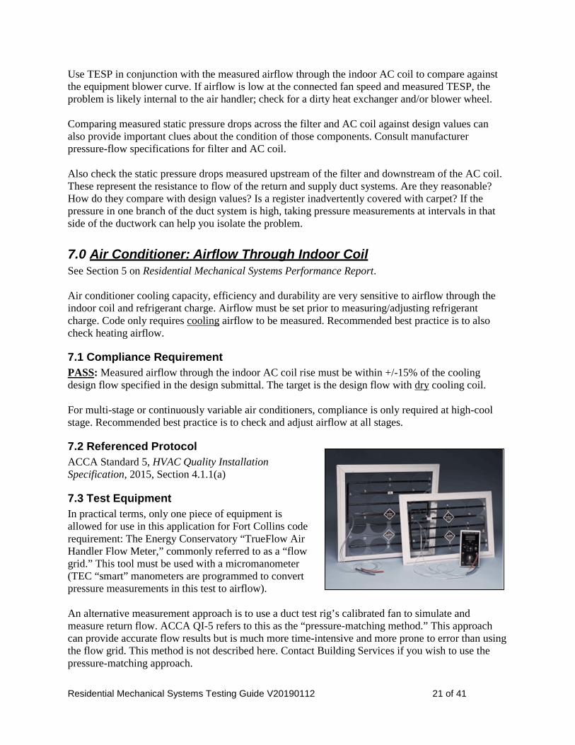
7.3 Test Equipment In practical terms, only one piece of equipment is allowed for use in this application for Fort Collins code requirement: The Energy Conservatory “TrueFlow Air Handler Flow Meter,” commonly referred to as a “flow grid.” This tool must be used with a micromanometer (TEC “smart” manometers are programmed to convert pressure measurements in this test to airflow). An alternative measurement approach is to use a duct test rig’s calibrated fan to simulate and measure return flow. ACCA QI-5 refers to this as the “pressure-matching method.” This approach can provide accurate flow results but is much more time-intensive and more prone to error than using the flow grid. This method is not described here. Contact Building Services if you wish to use the pressure-matching approach.

Residential Mechanical Systems Testing Guide V20190112 22 of 41
7.4 Measuring Air Handler Cooling Airflow The test protocol and flow grid instructions are outlined in detail in the TEC TrueFlow Operation Manual. There are two “Quick Guides” available as well, with condensed instructions for using the flow grid with the two TEC models of “smart” manometers. Tips and reminders:
• The same basic system setup is used for all tests of the forced-air heating and cooling system: − All registers open 100%, grilles in place − All interior doors open − Clean furnace filter of the type that will be in place when the house is sold. − Zone dampers open − Outdoor air intake damper open
• Close the bypass humidifier damper (“Summer” setting) so that all air passes through the air handler.
• Turn off the circuit breaker to the outdoor AC unit. During the winter, this prevents damage to the unit. During the summer, it prevents the coil from becoming wet.
• Operate the air handler at cooling speed.
• It is best to mount the flow grid in the air handler filter slot. If this is a single-return system, taking the airflow measurement at that return register is an option but will not account for any air pulled in through return ductwork leaks nor any air pulled in through an outdoor air intake connected to the return plenum. If you measure at this location, document it in “Testing Notes.”
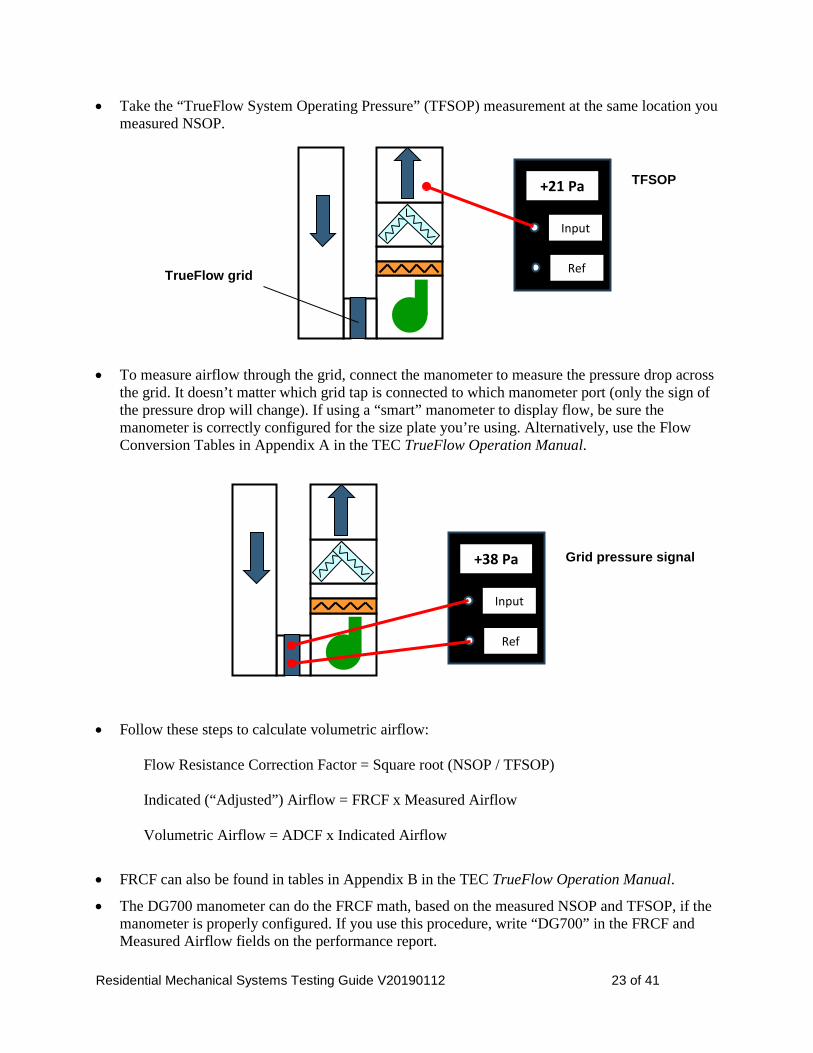
• For the “Normal System Operating Pressure” (NSOP) measurement, install a clean filter of the type that will be in place when the house is sold. Measure at the location shown as SP4 on the air handler diagram on the performance report.
• Install the flow grid: − Turn off the blower and replace the filter with the flow grid. Orient the flow grid with the
diamonds facing into the airflow (away from the blower). − Be sure there is no leakage at the filter slot when the flow grid is installed. If necessary, use
“temporary tape” to complete the seal. − Be sure the flow grid pressure tubes are not pinched where they emerge from the filter slot.
Input
Ref
+25 Pa
Normal filter (clean)
NSOP
Residential Mechanical Systems Testing Guide V20190112 23 of 41
• Take the “TrueFlow System Operating Pressure” (TFSOP) measurement at the same location you measured NSOP.
• To measure airflow through the grid, connect the manometer to measure the pressure drop across the grid. It doesn’t matter which grid tap is connected to which manometer port (only the sign of the pressure drop will change). If using a “smart” manometer to display flow, be sure the manometer is correctly configured for the size plate you’re using. Alternatively, use the Flow Conversion Tables in Appendix A in the TEC TrueFlow Operation Manual.
• Follow these steps to calculate volumetric airflow:
Flow Resistance Correction Factor = Square root (NSOP / TFSOP) Indicated (“Adjusted”) Airflow = FRCF x Measured Airflow Volumetric Airflow = ADCF x Indicated Airflow
• FRCF can also be found in tables in Appendix B in the TEC TrueFlow Operation Manual.
• The DG700 manometer can do the FRCF math, based on the measured NSOP and TFSOP, if the manometer is properly configured. If you use this procedure, write “DG700” in the FRCF and Measured Airflow fields on the performance report.
Input
Ref
+21 Pa TFSOP
TrueFlow grid
Input
Ref
+38 Pa Grid pressure signal

Residential Mechanical Systems Testing Guide V20190112 24 of 41
• ADCF is found in Appendix B of this guide or Table C.1.c in the TEC TrueFlow Operation Manual. (Use 5000’ elevation and the measured return air temperature.)
• When testing is finished, appropriately set the circuit breaker for the outdoor unit. If airflow is lower than the target range, look for high static pressures internal to the air handler, across the filter and AC coil or in the ductwork (see Section 6.0). If you cannot solve the problem by reducing static pressures, you may need to choose a higher speed tap for the blower. If airflow is higher than the target range, first check for disconnected ducts. If necessary, reduce the blower speed. Educate the builder and homeowner about the importance of using an appropriate filter, checking/replacing the filter on a consistent schedule, and leaving all registers open and not blocked by furnishings.
8.0 Gas Furnace: Manifold Gas Pressure See Section 5 on Residential Mechanical Systems Performance Report. In order for a gas furnace to operate safely and efficiently, manifold gas pressure must be within the equipment manufacturer’s specification. Recommended best practice is to also check line pressure coming into the regulator. Low manifold gas pressure is an under-fire situation that can lead to condensation at the heat exchanger. Excessive manifold pressure indicates over-firing that may be associated with incomplete combustion and excessive carbon monoxide generation. Excessive line gas pressure can rupture the manifold in the gas valve. A fringe benefit of checking line pressure is that air can be bled from the gas line, a time saver.
8.1 Compliance Requirement PASS: Measured manifold gas pressure must be within +/-5% of the manufacturer specified target. For multi-stage or continuously variable furnaces, compliance must be demonstrated at high-heat stage. Recommended best practice is to check and adjust pressure at all stages.
8.2 Referenced Protocol ACCA QI 5
8.3 Test Equipment • Digital manometer with pressure probe that screws into the gas valve pressure port. The
manometer must be calibrated for use with natural gas (check the OEM specifications). • Pressure adjustment tool
8.4 Target Manifold Pressure The first challenge is to determine the target manifold gas pressure. Depending on the manufacturer, the target pressure may depend on any or all of following variables:
Residential Mechanical Systems Testing Guide V20190112 25 of 41
• Altitude (5000’ for Fort Collins) • Average gas heat value at altitude (Xcel Energy data for Fort Collins delivery, 2001 through 2010
suggest an average of about 935 Btu/cf) or (de-rate 4 % per 1000 ft. - AFTER 2000 ft.) • Specific gravity of natural gas (Xcel Energy data, 2008, suggest a value of 0.61) • Orifice size Carefully read the details in the manufacturer’s installation manual to determine the target. Pay attention to the footnotes. (If you’re trying to determine the target pressure from the plate on the equipment, also pay attention to all notes.)
8.5 Measuring and Adjusting Manifold Pressure The important starting point is to read and carefully follow furnace manufacturer instructions, which vary from one piece of equipment to another. For example: • Some models of Carrier furnaces require the sealed combustion chamber cover to be removed
while manifold pressure is measured and adjusted. • Lennox Industries states that manifold pressure should not be adjusted on certain models of
modulating furnaces. Steps:
• Determine the target manifold pressure, above.
• Disable furnace power while installing the pressure tap on the low-pressure side of the regulator. Prepare the furnace per manufacturer instructions.
• When the manometer and tap are in place, fire the furnace and read the manifold pressure wrt to the zone in which the equipment is located.
• Adjust the regulator so the manifold pressure is within the target range.
• Turn off the furnace and restore to normal operating state.
9.0 Gas Furnace: Temperature Rise See Section 5 on Residential Mechanical Systems Performance Report. Furnace performance within the OEM specified temperature rise range is a sign that the furnace is operating safely, efficiently and durably. Temperature rise is determined by Btu input and air flow across the heat exchanger. Low temperature rise is associated with some combination of high airflow and/or low manifold gas pressure / firing rate. Condensation on the heat exchanger may result. Delivered air may be uncomfortably cool. High temperature rise is associated with high external static pressure, low airflow and/or high manifold gas pressure / firing rate. Problems with this situation include efficiency loss and shorter equipment lifetime. Temperature rise high enough so that the furnace cycles on the high temperature limit switch is a dangerous situation. Diagnose heat rise problems by measuring gas manifold pressure (Section 8.0), static pressures and air flow.

Residential Mechanical Systems Testing Guide V20190112 26 of 41
Measuring temperature rise on a new piece of equipment, with clean filter and ductwork and all registers open, is the best case for airflow. With occupants potentially closing or blocking registers, and accumulation of dirt on system components, airflow will decrease over time, increasing temperature rise. Therefore it is unwise to leave a new system operating near the top end of the temperature rise range. Educate the builder and homeowner about the importance of using the correct filter, checking/replacing the filter on a consistent schedule and leaving registers open and not blocked by furnishings.
9.1 Compliance Requirement PASS: Measured temperature rise must be within the manufacturer specified range. For multi-stage or continuously variable furnaces, compliance must only be checked at high-heat stage. Recommended best practice is to test and, if necessary, adjust temperature rise at all stages.
9.2 Referenced Protocol ACCA Standard 5, HVAC Quality Installation Specification, 2015, Section 4.5.1(a)ii.
9.3 Test Equipment Thermometer with probe long enough to sample average plenum temperature. A digital thermometer with low-mass thermocouple probe is recommended because response time is quick.
9.4 Measuring Temperature Rise • Be sure the thermometer is accurately calibrated.
• The same basic system setup is used for all tests involving the forced-air heating and cooling system: − All registers open 100%, grilles in place − All interior doors open − Clean furnace filter of the type that will be in place when the house is sold. − Zone dampers open
• Open the bypass humidifier damper (“Winter” setting), consistent with heating season operation.
• Fire the furnace on heating speed. For multi-stage equipment, operate on high stage.
• Let the furnace reach steady state temperature (minimum five minutes).
• Measure supply and return temperatures in locations with well-mixed air that will be representative of what’s entering and exiting the furnace. − Measure supply temperature above the AC coil so that the temperature probe doesn’t “see” the
hot heat exchanger; preferably downstream of the first fitting so that sufficient mixing has occurred.
− The best return temperature measurement location depends on what is being drawn into the return air system in the vicinity of the furnace. If a bypass humidifier is installed, the measurement must be taken well downstream of the point where it intersects the return. If there is an outdoor air intake connected to the return plenum, the measurement must be taken well downstream of that connection. Often the blower compartment is the most appropriate measurement location.

Residential Mechanical Systems Testing Guide V20190112 27 of 41
• Temperature rise = (Supply temperature) – (Return temperature)
• If the measured temperature rise falls within the OEM range but is within 10 F of the top of the allowable range, you are strongly advised to take steps to reduce temperature rise to closer to the middle of the range. If the manifold gas pressure is within range, airflow must be increased. This means reducing pressure drop – through duct or fitting changes or by cleaning dirty components – or increasing fan speed. If the final temperature rise result is within 10 F of the top of the OEM range, check both the “Pass” and “Caution” fields on the performance report.
10.0 Air Conditioner: Refrigerant Charge See Section 6 on Residential Mechanical Systems Performance Report. Refrigerant charge testing is included in the performance test report and testing and reporting is enforced during the warmer months of April - November. Become familiar with OEM instructions for the specific AC equipment you are testing. Additional information will be included in this guide as training is planned.
11.0 Room Air Flow See Section 7 on Residential Mechanical Systems Performance Report. Measurement of air flow delivery to individual rooms is currently not being enforced because (1) accurate measurement of supply air flow is challenging; and (2) the City’s performance focus is first on helping the industry succeed with delivering proper flows at the equipment. For now, there is only a cursory requirement in this regard to reduce the change of careless, significant installation errors. You must verify that all registers are cut through finish materials and moving air. You are encouraged to also perform a quick visual inspection of all ductwork to look for obvious problems such as crushed or kinked runs.
12.0 Room Pressure Balance See Section 7 on Residential Mechanical Systems Performance Report. Pressure imbalances in the house when the forced-air heating/cooling system is running can cause many problems: • Increase infiltration / exfiltration • Push moist indoor air into building assemblies • Pull soil gases into the house • Cause natural-draft combustion appliances to spill • Reduce supply or return flows • Reduce comfort • Create “ghost streaking” on carpet under doorways Testing room pressure balance is the easiest test in this mechanical systems testing suite.
Residential Mechanical Systems Testing Guide V20190112 28 of 41
12.1 Compliance Requirement PASS: Room-to-core pressure difference must be within the range -3 to +3 Pa. This applies to all rooms that include a supply and/or return register that can be isolated from the core of the house by closing a door. Regarding rooms for which questions often arise: • Laundry rooms. If a gas supply is stubbed for a clothes dryer, the laundry room must be tested.
Recommended best practice is to test all laundry rooms for pressure relief. (See information below regarding clothes dryer airflow.)
• Basements. If there is a door that can be closed between main level and basement, pressure drop across the door must be checked.
• Bathrooms. No requirement to test bathrooms.
12.2 Test Equipment The only equipment required is a manometer.
12.3 Measuring Room Pressure Balance • Be sure all registers are fully open.
• Turn off all exhaust fans.
• Close all interior doors.
• During cold weather, if there is air-conditioning, open the circuit breaker serving the outdoor AC unit.
• Operate the air handler on highest speed (typically cooling).
• Stand in the core of the house. At each room subject to the requirement, place a pressure tube under the door and read room pressure wrt core.
• In evaluating Pass/Fail, round to the nearest Pascal.
• When testing is finished, turn the circuit breaker to the outdoor AC unit back on. Rooms that fail may have excessive supply flow or insufficient pressure relief. Typical solutions for relieving pressure include installing / enlarging jumper ducts or transfer grilles. A rule-of-thumb for sizing transfer grilles is 1 square inch of net free area per cfm of airflow. Clothes dryer airflow generally ranges from 150 to 300 cfm, i.e. much higher than typical heating and cooling supply flows. For dryers to operate safely and efficiently when the laundry room door is closed, a substantially larger pressure relief device may be needed. Ideally you can test the pressure balance across the laundry room door with the dryer operating. In a newly completed house, that is often not possible and you’ll have to test using the air handler flow. In that case, look for a pressure drop considerably lower than the 3 Pascal limit.
Residential Mechanical Systems Testing Guide V20190112 29 of 41
13.0 Combustion Safety See Section 8 on Residential Mechanical Systems Performance Report. Combustion safety is critical for health and life safety. 100% of combustion products should always be vented out of the house. If not, they pose a variety of risks, ranging from irritants and water vapor to chronic sickness and death. Today’s tight construction supports larger pressure imbalances than older, leakier houses; even small negative pressures in the vicinity of a natural-draft combustion appliance can cause it to spill exhaust gases into the house. Appliances are tested with the house configured so that pressure in the combustion appliance zone (CAZ) is the most negative that might occur. This is known as “worst-case depressurization testing.” The presumption is that appliances that perform safely under worst-case conditions should perform safely under other operating conditions. (A weak point in a new home test is that a clothes dryer has not yet typically been installed; this large exhaust device will further depressurize the CAZ.) Combustion safety testing is only required when natural-draft appliances are installed. These include any appliances that draw house air for combustion and rely on buoyancy to vent the combustion products. Appliances that must be tested include: • Natural-draft gas water heater • Induced-draft gas furnace • Induced-draft gas boiler • Natural-draft gas fireplace Power-vented, sealed-combustion and direct-vent appliances have no combustion safety test requirement. Gas cooktops and ovens are not required to be tested under the current code. [TBD: Wood-burning fireplaces and stoves]
13.1 Compliance Requirement PASS: Tested appliances must fall within the following three ranges, under worst-case depressurization conditions: • Spillage= 60 seconds or less • Draft = within BPI acceptable draft pressure range • Carbon monoxide (CO) level in undiluted flue gas = 100 ppm or less [check: air-free?] Recommended best practice is that the CO level does not exceed 25 ppm.
13.2 Referenced Protocol Building Performance Institute (BPI) Combustion Safety Test Procedure for Vented Appliances. This protocol was initially written for existing home situations. The description in this section adapts it to apply more specifically to new construction.
13.3 Test Equipment • Timer (watch or cell phone that can measure seconds) • Carbon monoxide measuring device • Micro-manometer • Static pressure probe
Residential Mechanical Systems Testing Guide V20190112 30 of 41
• Smoke pencil or mirror • Thermometer (for outdoor temperature)
13.4 Worst-Case CAZ Depressurization Setup Due to the small pressures involved, this setup will be challenging in windy conditions. Determine which appliances must be tested. For each, determine their CAZ. The steps that follow refer to testing one or more appliances within a particular CAZ.
Initial Setup 1) Close all exterior doors, windows, and fireplace dampers. 2) Set all draft-hooded appliances that must be tested to Pilot. Turn off all other combustion
appliances. 3) With the manometer in the CAZ, connect a tube from outdoors to the Reference port to read CAZ
pressure wrt outdoors. All CAZ pressure measurements below are wrt outdoors.
Baseline Pressure 4) Note the baseline CAZ pressure.
Establish Worst-Case CAZ Depressurization 5) Turn on all exhaust fans. These typically include bath and laundry fans, vented kitchen hood and
clothes dryer if present (a clothes dryer can be simulated with a blower door exhausting 200 cfm from the house). If an active radon system is installed, be sure the radon fan is operating. (Do NOT operate whole-house fans.)
6) Close all interior doors except to rooms where exhaust fans are operating. 7) Note the CAZ pressure. 8) Operate the air handler fan at highest speed; typically “fan-only” or “cooling” setting (if
operating at “cooling” setting when outdoor temperature is below 60 F, first turn off power to the AC outdoor unit).
9) Note the CAZ pressure. If the CAZ pressure became more negative with the air handler fan running, leave it on. If not, turn the air handler fan off.
10) If the mechanical equipment is in a mechanical room or basement with a door, measure CAZ pressure both with the door open and closed; leave the door in whichever position the CAZ pressure is more negative. The house is now in worst-case CAZ depressurization condition.
11) Document the house setup. 12) Calculate and record worst-case net CAZ depressurization.
Net CAZ depressurization = (Worst-case CAZ pressure) – (Baseline CAZ pressure) Example. The baseline CAZ pressure is -2.3 Pa. The worst-case CAZ pressure is -6.7 Pa. Worst-case net CAZ depressurization = -6.7 - (-2.3) = -4.4 Pa
Residential Mechanical Systems Testing Guide V20190112 31 of 41
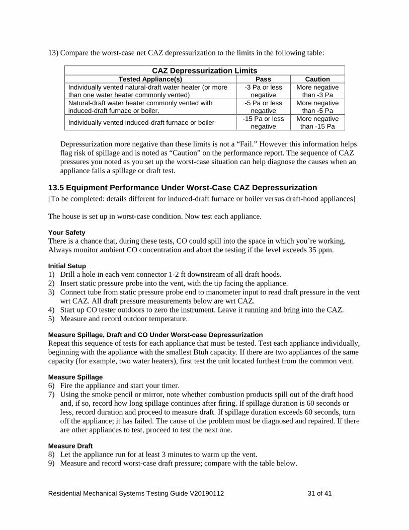
13) Compare the worst-case net CAZ depressurization to the limits in the following table:
Depressurization more negative than these limits is not a “Fail.” However this information helps flag risk of spillage and is noted as “Caution” on the performance report. The sequence of CAZ pressures you noted as you set up the worst-case situation can help diagnose the causes when an appliance fails a spillage or draft test.
13.5 Equipment Performance Under Worst-Case CAZ Depressurization [To be completed: details different for induced-draft furnace or boiler versus draft-hood appliances] The house is set up in worst-case condition. Now test each appliance.
Your Safety There is a chance that, during these tests, CO could spill into the space in which you’re working. Always monitor ambient CO concentration and abort the testing if the level exceeds 35 ppm.
Initial Setup 1) Drill a hole in each vent connector 1-2 ft downstream of all draft hoods. 2) Insert static pressure probe into the vent, with the tip facing the appliance. 3) Connect tube from static pressure probe end to manometer input to read draft pressure in the vent
wrt CAZ. All draft pressure measurements below are wrt CAZ. 4) Start up CO tester outdoors to zero the instrument. Leave it running and bring into the CAZ. 5) Measure and record outdoor temperature.
Measure Spillage, Draft and CO Under Worst-case Depressurization Repeat this sequence of tests for each appliance that must be tested. Test each appliance individually, beginning with the appliance with the smallest Btuh capacity. If there are two appliances of the same capacity (for example, two water heaters), first test the unit located furthest from the common vent.
Measure Spillage 6) Fire the appliance and start your timer. 7) Using the smoke pencil or mirror, note whether combustion products spill out of the draft hood
and, if so, record how long spillage continues after firing. If spillage duration is 60 seconds or less, record duration and proceed to measure draft. If spillage duration exceeds 60 seconds, turn off the appliance; it has failed. The cause of the problem must be diagnosed and repaired. If there are other appliances to test, proceed to test the next one.
Measure Draft 8) Let the appliance run for at least 3 minutes to warm up the vent. 9) Measure and record worst-case draft pressure; compare with the table below.
CAZ Depressurization Limits Tested Appliance(s) Pass Caution
Individually vented natural-draft water heater (or more than one water heater commonly vented)
-3 Pa or less negative
More negative than -3 Pa
Natural-draft water heater commonly vented with induced-draft furnace or boiler.
-5 Pa or less negative
More negative than -5 Pa
Individually vented induced-draft furnace or boiler -15 Pa or less negative
More negative than -15 Pa

Residential Mechanical Systems Testing Guide V20190112 32 of 41
In evaluating Pass/Fail, pay close attention to the sign of the pressure difference. (Example: For outdoor temperature 35 F, draft pressure must be -4 Pa or more negative. -8.5 Pa passes, -3.2 Pa fails.)
* Pass = Measured draft pressure is more negative than the number shown for the outdoor temperature at time of test.
Measure Undiluted Flue Gas CO Level 10) Let appliance run for at least 5 minutes (or until the vent temperature is constant). 11) Insert CO test probe into a location where it samples undiluted flue gases, below the draft hood.
For a conventional gas water heater, sample both sides of the baffle in the internal flue. 12) Measure and record CO concentration in undiluted flue gases. If the CO level is 100 ppm or below, you’re finished testing this appliance. If the CO level is between 25 and 100 ppm, adjustment is strongly recommended to bring it below 25 ppm. If that is not possible, flag the Caution box on the performance report. If the CO level exceeds 100 ppm, the problem must be diagnosed and repaired. If there are other appliances to test, proceed to test the next one (next smallest Btuh capacity or closer to the common vent) under worst-case conditions.
14.0 System Controls See Section 9 on Residential Mechanical Systems Performance Report. Installed system controls for heating, cooling, local exhaust, whole-house ventilation must operate in accordance with design intent, as documented in the mechanical design submittal. This is straightforward with simple systems with a small number of operating modes; more complex as equipment and controls become more sophisticated (e.g. multi-stage equipment, zoned distribution systems).
14.1 Compliance Requirement PASS: Controls for each installed mechanical system in the list in the performance report must operate consistently with design intent.
14.2 Testing Controls [Remainder to be completed]
ACCEPTABLE DRAFT PRESSURES FOR NATURAL-DRAFT GAS APPLIANCES*
Outdoor temperature (F) <20 21-40 41-60 61-80 >80
Minimum draft pressure (Pa) -5 -4 -3 -2 -1

Residential Mechanical Systems Testing Guide V20190112 33 of 41
Appendix A: Testing Equipment Useful For Multiple Tests
15.1 Manometer
Allowed for these tests Almost all of the tests require a manometer.
General information Manometers are the workhorses of the testing toolbox. Manometers measure pressure differences between one point and another. For residential HVAC applications, these pressure differences are often converted to other parameters such as airflow. Manometers are available from several manufacturers. Choices include: • Analog or digital. Digital is the only realistic choice for today’s testing
requirements. • One channel or two channel. Dual channel units are
recommended because they make some tests more convenient / quicker.
• Units. Typical choices for residential HVAC applications are Pascals (Pa) or inches of water column (IWC). Some instruments offer both.
• Precision. 0.1 Pa (0.0004 IWC) accuracy is required for some tests. Manometers measuring to this level of precision are typically known as “micromanometers.”
• Brains. Standard manometers only measure instantaneous pressure differences. “Smart” manometers have built-in microcomputers that allow time averaging and – when paired with other types of measurement tools – convert pressure measurements to other parameters such as air velocity and flow.
• Multi-function. Some manometers add additional capabilities such as temperature measurement.
Reminders / tips
• Always pay close attention to which pressure you are measuring with respect to (wrt) which other pressure. Write it down (e.g. “Vent pressure wrt CAZ”). Part of keeping track is noting the sign of the pressure difference (+ or -). Being diligent about this will make your testing job much easier!
• Unit conversions: − Multiply IWC x 250 to convert to Pa − Multiply Pa x 0.004 to convert to IWC
• “Smart” manometers can save time and reduce error. To take advantage of their capabilities to convert pressure measurements to other parameters, they must be used only with matched equipment (typically from the same manufacturer) and must be correctly set up for the equipment configuration.
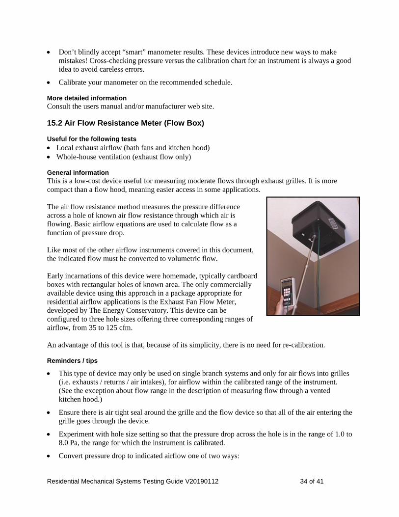
Residential Mechanical Systems Testing Guide V20190112 34 of 41
• Don’t blindly accept “smart” manometer results. These devices introduce new ways to make mistakes! Cross-checking pressure versus the calibration chart for an instrument is always a good idea to avoid careless errors.
• Calibrate your manometer on the recommended schedule.
More detailed information Consult the users manual and/or manufacturer web site.
15.2 Air Flow Resistance Meter (Flow Box)
Useful for the following tests • Local exhaust airflow (bath fans and kitchen hood) • Whole-house ventilation (exhaust flow only)
General information This is a low-cost device useful for measuring moderate flows through exhaust grilles. It is more compact than a flow hood, meaning easier access in some applications. The air flow resistance method measures the pressure difference across a hole of known air flow resistance through which air is flowing. Basic airflow equations are used to calculate flow as a function of pressure drop. Like most of the other airflow instruments covered in this document, the indicated flow must be converted to volumetric flow. Early incarnations of this device were homemade, typically cardboard boxes with rectangular holes of known area. The only commercially available device using this approach in a package appropriate for residential airflow applications is the Exhaust Fan Flow Meter, developed by The Energy Conservatory. This device can be configured to three hole sizes offering three corresponding ranges of airflow, from 35 to 125 cfm. An advantage of this tool is that, because of its simplicity, there is no need for re-calibration.
Reminders / tips
• This type of device may only be used on single branch systems and only for air flows into grilles (i.e. exhausts / returns / air intakes), for airflow within the calibrated range of the instrument. (See the exception about flow range in the description of measuring flow through a vented kitchen hood.)
• Ensure there is air tight seal around the grille and the flow device so that all of the air entering the grille goes through the device.
• Experiment with hole size setting so that the pressure drop across the hole is in the range of 1.0 to 8.0 Pa, the range for which the instrument is calibrated.
• Convert pressure drop to indicated airflow one of two ways:
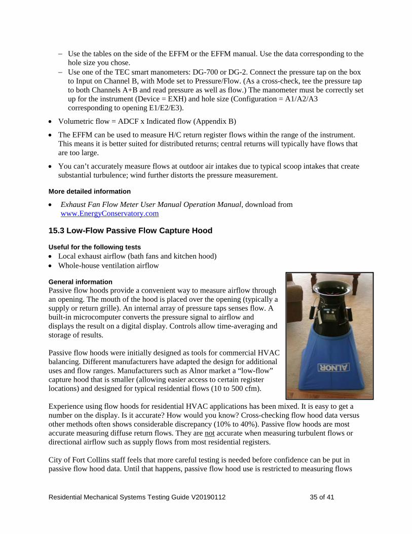
Residential Mechanical Systems Testing Guide V20190112 35 of 41
− Use the tables on the side of the EFFM or the EFFM manual. Use the data corresponding to the hole size you chose.
− Use one of the TEC smart manometers: DG-700 or DG-2. Connect the pressure tap on the box to Input on Channel B, with Mode set to Pressure/Flow. (As a cross-check, tee the pressure tap to both Channels A+B and read pressure as well as flow.) The manometer must be correctly set up for the instrument (Device = EXH) and hole size (Configuration = A1/A2/A3 corresponding to opening E1/E2/E3).
• Volumetric flow = ADCF x Indicated flow (Appendix B)
• The EFFM can be used to measure H/C return register flows within the range of the instrument. This means it is better suited for distributed returns; central returns will typically have flows that are too large.
• You can’t accurately measure flows at outdoor air intakes due to typical scoop intakes that create substantial turbulence; wind further distorts the pressure measurement.
More detailed information
• Exhaust Fan Flow Meter User Manual Operation Manual, download from www.EnergyConservatory.com
15.3 Low-Flow Passive Flow Capture Hood
Useful for the following tests • Local exhaust airflow (bath fans and kitchen hood) • Whole-house ventilation airflow
General information Passive flow hoods provide a convenient way to measure airflow through an opening. The mouth of the hood is placed over the opening (typically a supply or return grille). An internal array of pressure taps senses flow. A built-in microcomputer converts the pressure signal to airflow and displays the result on a digital display. Controls allow time-averaging and storage of results. Passive flow hoods were initially designed as tools for commercial HVAC balancing. Different manufacturers have adapted the design for additional uses and flow ranges. Manufacturers such as Alnor market a “low-flow” capture hood that is smaller (allowing easier access to certain register locations) and designed for typical residential flows (10 to 500 cfm). Experience using flow hoods for residential HVAC applications has been mixed. It is easy to get a number on the display. Is it accurate? How would you know? Cross-checking flow hood data versus other methods often shows considerable discrepancy (10% to 40%). Passive flow hoods are most accurate measuring diffuse return flows. They are not accurate when measuring turbulent flows or directional airflow such as supply flows from most residential registers. City of Fort Collins staff feels that more careful testing is needed before confidence can be put in passive flow hood data. Until that happens, passive flow hood use is restricted to measuring flows

Residential Mechanical Systems Testing Guide V20190112 36 of 41
into a grille: bath fan flow at interior grille, kitchen hood flow at interior grille, whole-house ventilation at intake grilles where flow is laminar/diffuse.
Reminders / tips
• Flow hoods appear simple to use. Just because they give a digital readout of cfm doesn’t mean the result is correct! Flow hoods are often misapplied.
• Ensure there is air tight seal around the grille and the flow device so that all of the air entering the grille goes through the device.
• The flow measurement will typically be most accurate when the grille is centered in mouth of the flow hood.
• You will not be able to access some grilles due to the size of the flow hood.
• Do not take data when the airflow is outside of the hood’s calibrated range.
• Convert indicated airflow to volumetric flow using specific instructions provided by the hood manufacturer. See Appendix B.
• Calibrate your flow hood on the recommended schedule. Plan ahead for the time this will take.
More detailed information Consult the users manual and/or manufacturer web site. A web browser search of: “Accuracy of Flow Hoods in Residential Applications,” LBNL, 2002 will yield pertinent results.
15.4 Powered Flow Capture Hood
Useful for the following tests • Flow measurements at supply or return grilles (heating, cooling,
ventilation)
General information A powered flow hood overcomes some of the limitations described for passive flow hoods. The device incorporates a flow conditioner to straighten the air flow and an adjustable-speed fan that is used to neutralize backpressure. This lets the powered hood accurately measure directional flows. The Energy Conservatory “FlowBlaster” was the first commercially available powered flow hood; the flow hood portion is designed to be paired with a DuctBlaster fan and manometer that many testing technicians may already own. It is calibrated over a range of 10 to 300 cfm supply and return flows. The RetroTec “FlowFinder” powered flow hood measures 6 to 326 CFM in full zero balance mode and up to 503 CFM in compensated mode.
More detailed information FlowBlaster Operation Manual, download from www.EnergyConservatory.com FlowFinder Operation Manual, download from http://www.retrotec.com
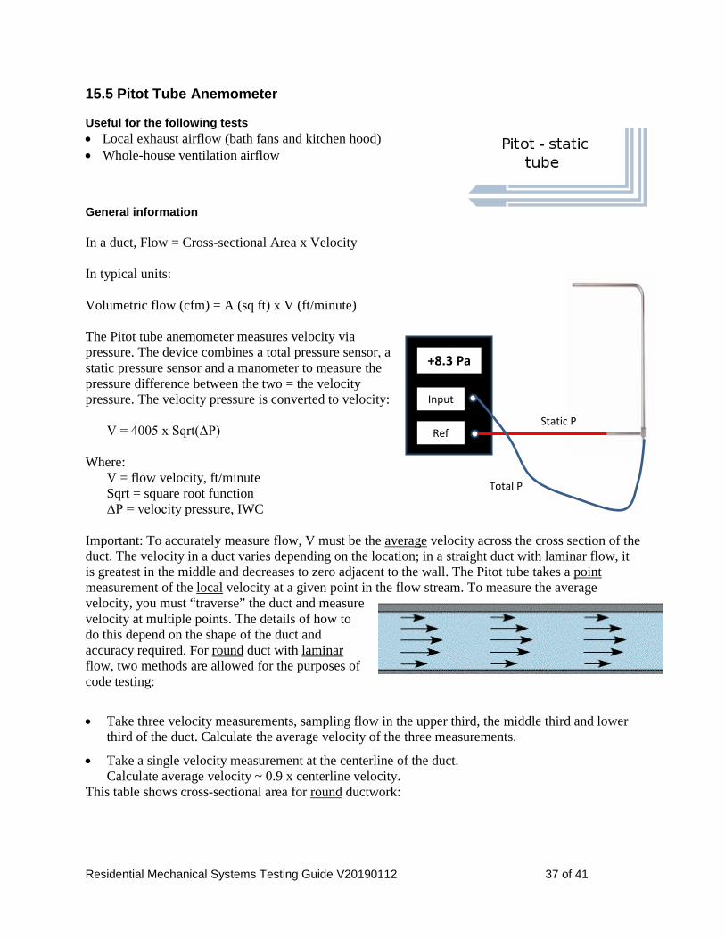
Residential Mechanical Systems Testing Guide V20190112 37 of 41
15.5 Pitot Tube Anemometer
Useful for the following tests • Local exhaust airflow (bath fans and kitchen hood) • Whole-house ventilation airflow
General information In a duct, Flow = Cross-sectional Area x Velocity In typical units: Volumetric flow (cfm) = A (sq ft) x V (ft/minute) The Pitot tube anemometer measures velocity via pressure. The device combines a total pressure sensor, a static pressure sensor and a manometer to measure the pressure difference between the two = the velocity pressure. The velocity pressure is converted to velocity:
V = 4005 x Sqrt(ΔP) Where:
V = flow velocity, ft/minute Sqrt = square root function ΔP = velocity pressure, IWC
Important: To accurately measure flow, V must be the average velocity across the cross section of the duct. The velocity in a duct varies depending on the location; in a straight duct with laminar flow, it is greatest in the middle and decreases to zero adjacent to the wall. The Pitot tube takes a point measurement of the local velocity at a given point in the flow stream. To measure the average velocity, you must “traverse” the duct and measure velocity at multiple points. The details of how to do this depend on the shape of the duct and accuracy required. For round duct with laminar flow, two methods are allowed for the purposes of code testing:
• Take three velocity measurements, sampling flow in the upper third, the middle third and lower third of the duct. Calculate the average velocity of the three measurements.
• Take a single velocity measurement at the centerline of the duct. Calculate average velocity ~ 0.9 x centerline velocity.
This table shows cross-sectional area for round ductwork:
Input
Ref
+8.3 Pa
Static P
Total P

Residential Mechanical Systems Testing Guide V20190112 38 of 41
For rectangular ductwork, traverses must be made across both width and height of the duct. See the reference from Fluke, below. A pitot-tube anemometer has several advantages: • Low cost for the Pitot tube (you’ll have a manometer for other tests) • Only a small hole in the duct is required; no need to disassemble the duct • No calibration is needed.
Reminders / tips
• The ideal location for the traverse in a supply duct is in a straight section of duct with 10 straight equivalent duct diameters upstream, and 3 straight equivalent duct diameters downstream of the traverse plane, although a minimum of 5 duct equivalent diameters upstream and 1 duct equivalent diameter downstream may give adequate results.
When the traverse is located close to the fan, flow conditions are usually more favorable upstream, i.e. on the return side. The traverse on the upstream side should be 0.5 duct equivalent diameters upstream of the fan inlet (per Fluke reference below). You won’t always be able to measure in these locations. Be aware of the impacts of turbulence on your result as you stray from the ideal.
• The probe must be held parallel to the duct, tip facing upstream.
• Don’t forget to use average velocity rather than centerline velocity.
• “Smart” manometers may include built-in functions to do the calculations and read either velocity (FPM) or airflow (CFM). Two manometers with these capabilities are the Fluke 922 and Energy Conservatory DG-700. To use these modes, the manometer must be correctly configured.
• Volumetric flow = ADCF x Indicated flow (Appendix B)
More detailed information
• Consult detailed instructions provided by manufacturers of smart manometers that are designed to be used in a Pitot tube anemometer setup. − The Energy Conservatory DG700 manual, Section 6.5
• Duct traverse instructions for rectangular ducts, using Fluke 922 manometer: www.fluke.com/Fluke/usen/community/fluke-news-plus/ArticleCategories/HVAC/Duct+Traversal.htm
Round duct cross-sectional area
Duct Diameter (inches)
Duct Radius (feet)
Duct Area (ft2)
4 0.167 0.087 5 0.208 0.136 6 0.25 0.196 8 0.33 0.349
10 0.42 0.545
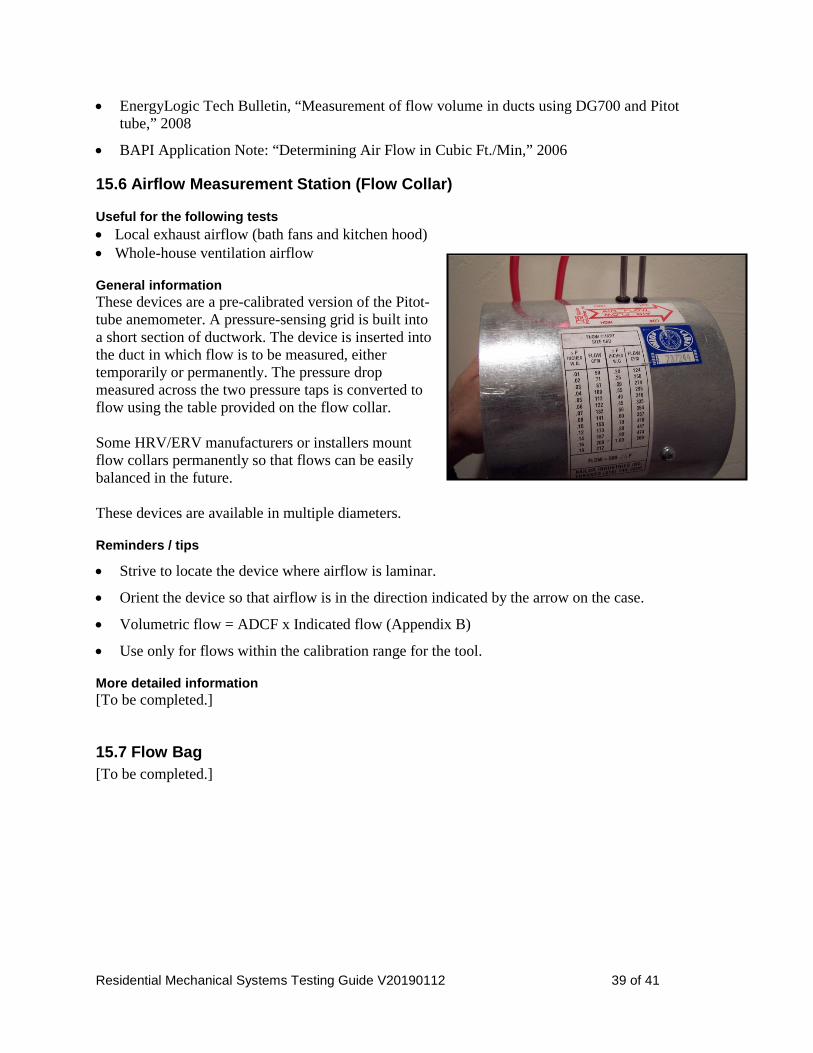
Residential Mechanical Systems Testing Guide V20190112 39 of 41
• EnergyLogic Tech Bulletin, “Measurement of flow volume in ducts using DG700 and Pitot tube,” 2008
• BAPI Application Note: “Determining Air Flow in Cubic Ft./Min,” 2006
15.6 Airflow Measurement Station (Flow Collar)
Useful for the following tests • Local exhaust airflow (bath fans and kitchen hood) • Whole-house ventilation airflow
General information These devices are a pre-calibrated version of the Pitot-tube anemometer. A pressure-sensing grid is built into a short section of ductwork. The device is inserted into the duct in which flow is to be measured, either temporarily or permanently. The pressure drop measured across the two pressure taps is converted to flow using the table provided on the flow collar. Some HRV/ERV manufacturers or installers mount flow collars permanently so that flows can be easily balanced in the future. These devices are available in multiple diameters.
Reminders / tips
• Strive to locate the device where airflow is laminar.
• Orient the device so that airflow is in the direction indicated by the arrow on the case.
• Volumetric flow = ADCF x Indicated flow (Appendix B)
• Use only for flows within the calibration range for the tool.
More detailed information [To be completed.]
15.7 Flow Bag [To be completed.]

Residential Mechanical Systems Testing Guide V20190112 40 of 41
Appendix B: Correcting Flow Data for Air Density Air density varies widely with pressure and temperature. When measuring air flow rates using tools that sense pressure, you must account for these variations. In practice, the most important pressure variable is altitude: 5000’ air has 83% of the density of sea level air.
16.1 Indicated and Volumetric Flow The outputs from tools used for the kinds of measurements described in this guide are considered “Indicated Flow.” The tool registers this result without knowing the density of air passing through it. The Indicated Flow value will vary depending on density. So that design flows and measured flows (and flows measured by different people, at different times, under different conditions) can be compared on an apples-to-apples basis, Indicated Flow must be converted to “Volumetric Flow.” For the purposes of the Fort Collins code, this means converting Indicated Flow, under measurement conditions, to an equivalent flow at the standard air density at 5000 feet, 70 degrees F. To make this conversion, you must have the “Air Density Correction Factor” (ADCF) specific to the tool, altitude and temperature.
Volumetric Flow (CFM 5000’) = ADCF x Indicated Flow (CFM) The tool manufacturer should provide ADCF data. Sometimes it is hard to obtain. Keep reading.
16.2 Air Density Correction Factors (ADCF) The information that follows is what City of Fort Collins staff have been able to compile to date for commonly used tools. There appear to be two sets of ADCF: one for the Alnor LoFlo Balometer, the rest for all the other tools we have encountered to date. In the absence of other information, use the numbers summarized in the table or chart, with references that follow.
5000' Air Density Correction Factors Air Temperature Through Tool (F) Many Flow Tools* Alnor LoFlo Balometer
0 1.023 1.042 10 1.034 1.064 20 1.045 1.087 30 1.056 1.109 40 1.067 1.132 50 1.077 1.155 60 1.088 1.177 70 1.098 1.200 80 1.109 1.223 90 1.119 1.245
100 1.129 1.268 * Pitot tube anemometer; flow collar; The Energy Conservatory flow box, flow grid, DuctBlaster, FlowBlaster
OK to round air temperature to nearest 10F.

Residential Mechanical Systems Testing Guide V20190112 41 of 41
1.00
1.05
1.10
1.15
1.20
1.25
1.30
0 10 20 30 40 50 60 70 80 90 100
Corr
ectio
n Fa
ctor
Air Temperature Through Tool (F)
5000' Air Density Correction Factors
Alnor LoFloBalometer
Many OtherFlow Tools*
* Pitot tube anemometer; flow collar; The Energy Conservatory flow box, flow grid, DuctBlaster, FlowBlaster
OK to round air temperature to nearest 10F.
Alnor 6200 LoFlo Balometer Instructions on converting Indicated Flow to Volumetric Flow are provided in the manual for this passive flow hood, Appendix A: “Correction Factors for Standard Flow Rate to Actual Flow Rate.” The results of applying the equations for 5000’ elevation are summarized in the table and graph above.
“Many other flow tools” Most of the tools to which the other ADCF line applies appear to be based on velocity measurement using Pitot tubes. These include the Pitot tube anemometer; flow collar; The Energy Conservatory flow grid and DuctBlaster. Per Energy Conservatory staff, the same ADCFs also apply to the Energy Conservatory flow box. The basic equation governing the density conversions can be found in an article by Dwyer Instruments: “Calculating Air Velocity from Velocity Pressure” (www.dwyer-inst.com/Products/AirVelocityIntroduction.cfm). The results of applying the equation for 5000’ elevation are summarized in the table and graph above. They are identical to Table C.1.c in The Energy Conservatory TrueFlow Air Handler Flow Meter Operation Manual.