
Research Article Numerical Investigation of Pressure...
12
Research Article Numerical Investigation of Pressure Fluctuation Characteristics in a Centrifugal Pump with Variable Axial Clearance Lei Cao, Zhengwei Wang, Yexiang Xiao, and Yongyao Luo State Key Laboratory of Hydroscience and Engineering and Department of ermal Engineering, Tsinghua University, Beijing 100084, China Correspondence should be addressed to Zhengwei Wang; [email protected] Received 9 December 2015; Revised 22 March 2016; Accepted 5 April 2016 Academic Editor: Jiun-Jih Miau Copyright © 2016 Lei Cao et al. is is an open access article distributed under the Creative Commons Attribution License, which permits unrestricted use, distribution, and reproduction in any medium, provided the original work is properly cited. Clearance flows in the sidewall gaps of centrifugal pumps are unsteady as well as main flows in the volute casing and impeller, which may cause vibration and noise, and the corresponding pressure fluctuations are related to the axial clearance size. In this paper, unsteady numerical simulations were conducted to predict the unsteady flows within the entire flow passage of a centrifugal pump operating in the design condition. Pressure fluctuation characteristics in the volute casing, impeller, and sidewall gaps were investigated with three axial clearance sizes. Results show that an axial clearance variation affects the pressure fluctuation characteristics in each flow domain by different degree. e greatest pressure fluctuation occurs at the blade pressure surface and is almost not influenced by the axial clearance variation which has a certainly effect on the pressure fluctuation characteristics around the tongue. e maximum pressure fluctuation amplitude in the sidewall gaps is larger than that in the volute casing, and different spectrum characteristics show up in the three models due to the interaction between the clearance flow and the main flow as well as the rotor-stator interaction. erefore, clearance flow should be taken into consideration in the hydraulic design of centrifugal pumps. 1. Introduction Unsteady flows in centrifugal pumps are always paid attention to in engineering, which can cause vibration, noise, and even fatigue failure. Pressure fluctuation is one of the most common phenomena of unsteady flows. Considerable inves- tigations [1–12] have been performed on pressure fluctuation characteristics in volute casings and impellers of centrifugal pumps, concluding that blade-tongue interaction plays a dominant role in causing fluctuating main flows, and the influencing factors including flow rate and impeller-tongue gap size have been analyzed. But flows in sidewall gaps, which refer to the space between impeller shrouds and casing covers, are usually ignored. However, Uy and Brennen [13] found that the leakage path had considerable influence on the rotor dynamic force when they did some experiments for centrifugal pumps whose shrouds were in different shapes. Increasing scholars are paying attention to the clearance flows in centrifugal pumps in recent years. Spence and Amaral- Teixeira [14] carried out an unsteady numerical simulation for a double suction pump and thought that the deviation in pressure fluctuations between the numerical and experi- mental results was due to the simplified front shroud in the simulation. Park and Morrison [15] probed into the interac- tion between the back clearance flow and impeller passage flow by calculating the pressure fluctuations in a centrifugal pump with a semiopen impeller. Pei et al. [16–19] claimed the unstable flow in the sidewall gaps could not be ignored for the sake of an accurate calculation and analysis of the pressure fluctuation intensity and turbulence intensity distribution in the entire flow passage of a single-blade centrifugal pump. In addition, the size of the leakage path has certain influence on the main flow field. Radial clearance sizes, usually referring to wear ring sizes, were studied in a centrifugal pump by Liu et al. [20] and they found that the velocity and pressure distribu- tion in the front wear ring was related to its radial dimension. Many scholars [21–24] also experimentally and theoretically discovered that changing the distance between a rotating wall and a stationary wall would make the flow structure between the two walls show different characters. However, Hindawi Publishing Corporation International Journal of Rotating Machinery Volume 2016, Article ID 9306314, 11 pages http://dx.doi.org/10.1155/2016/9306314
Transcript of Research Article Numerical Investigation of Pressure...

Research ArticleNumerical Investigation of Pressure Fluctuation Characteristicsin a Centrifugal Pump with Variable Axial Clearance
Lei Cao, Zhengwei Wang, Yexiang Xiao, and Yongyao Luo
State Key Laboratory of Hydroscience and Engineering and Department of Thermal Engineering,Tsinghua University, Beijing 100084, China
Correspondence should be addressed to Zhengwei Wang; [email protected]
Received 9 December 2015; Revised 22 March 2016; Accepted 5 April 2016
Academic Editor: Jiun-Jih Miau
Copyright © 2016 Lei Cao et al. This is an open access article distributed under the Creative Commons Attribution License, whichpermits unrestricted use, distribution, and reproduction in any medium, provided the original work is properly cited.
Clearance flows in the sidewall gaps of centrifugal pumps are unsteady as well as main flows in the volute casing and impeller,which may cause vibration and noise, and the corresponding pressure fluctuations are related to the axial clearance size. In thispaper, unsteady numerical simulations were conducted to predict the unsteady flows within the entire flow passage of a centrifugalpump operating in the design condition. Pressure fluctuation characteristics in the volute casing, impeller, and sidewall gapswere investigated with three axial clearance sizes. Results show that an axial clearance variation affects the pressure fluctuationcharacteristics in each flow domain by different degree.The greatest pressure fluctuation occurs at the blade pressure surface and isalmost not influenced by the axial clearance variation which has a certainly effect on the pressure fluctuation characteristics aroundthe tongue. The maximum pressure fluctuation amplitude in the sidewall gaps is larger than that in the volute casing, and differentspectrum characteristics show up in the three models due to the interaction between the clearance flow and the main flow as wellas the rotor-stator interaction. Therefore, clearance flow should be taken into consideration in the hydraulic design of centrifugalpumps.
1. Introduction
Unsteady flows in centrifugal pumps are always paid attentionto in engineering, which can cause vibration, noise, andeven fatigue failure. Pressure fluctuation is one of the mostcommon phenomena of unsteady flows. Considerable inves-tigations [1–12] have been performed on pressure fluctuationcharacteristics in volute casings and impellers of centrifugalpumps, concluding that blade-tongue interaction plays adominant role in causing fluctuating main flows, and theinfluencing factors including flow rate and impeller-tonguegap size have been analyzed. But flows in sidewall gaps,which refer to the space between impeller shrouds and casingcovers, are usually ignored. However, Uy and Brennen [13]found that the leakage path had considerable influence onthe rotor dynamic force when they did some experiments forcentrifugal pumps whose shrouds were in different shapes.Increasing scholars are paying attention to the clearance flowsin centrifugal pumps in recent years. Spence and Amaral-Teixeira [14] carried out an unsteady numerical simulation
for a double suction pump and thought that the deviationin pressure fluctuations between the numerical and experi-mental results was due to the simplified front shroud in thesimulation. Park and Morrison [15] probed into the interac-tion between the back clearance flow and impeller passageflow by calculating the pressure fluctuations in a centrifugalpump with a semiopen impeller. Pei et al. [16–19] claimed theunstable flow in the sidewall gaps could not be ignored for thesake of an accurate calculation and analysis of the pressurefluctuation intensity and turbulence intensity distribution inthe entire flow passage of a single-blade centrifugal pump. Inaddition, the size of the leakage path has certain influence onthemain flow field. Radial clearance sizes, usually referring towear ring sizes, were studied in a centrifugal pump by Liu etal. [20] and they found that the velocity and pressure distribu-tion in the front wear ring was related to its radial dimension.Many scholars [21–24] also experimentally and theoreticallydiscovered that changing the distance between a rotatingwall and a stationary wall would make the flow structurebetween the two walls show different characters. However,
Hindawi Publishing CorporationInternational Journal of Rotating MachineryVolume 2016, Article ID 9306314, 11 pageshttp://dx.doi.org/10.1155/2016/9306314

2 International Journal of Rotating Machinery
X
X
Suction pipeBAC
Impeller Y
ZBack blade
Y
Z
Volute casing
X
Front gap
Y
Z
Back sidewall gap
BC1
X
Y
Z
Front gap
Back-blade domain
FC1
X
Y
Z
cf
cb
Figure 1: Geometry of the centrifugal pump.
little research has been done to analyze the influence ofaxial clearance sizes on the unsteady flow characteristics incentrifugal pumps. Therefore, it is meaningful to discuss theeffect of axial clearance sizes on the pressure fluctuations incentrifugal pumps, which will facilitate the optimal designand safe operation of centrifugal pumps.
In this paper, unsteady numerical simulations were car-ried out in the design condition for the entire flow passage ofa centrifugal pump.Three axial clearance sizes were obtainedby moving the impeller along the axial direction.The numer-ical codes were first validated by a model test. Then weanalyzed the pressure fluctuation characteristics in each flowdomain and gave an understanding on how axial clearancesizes influenced the unsteady flows in centrifugal pumps.
2. Numerical Method
2.1. Physical Model and Grid. The centrifugal pump studiedin this paper has a shrouded impeller with nine back bladeson the front shroud, whose basic parameters are given inTable 1. The 3D entire flow passage, including suction pipe,impeller, volute casing, front sidewall gap, and back sidewallgap, was built by the 3D modeling software UG NX 6.0.
The actual front sidewall gap was divided into two domains,the rotating back-blade domain and the stationary front gap(the front gapmentioned below refers to this stationary part),to better predict the flow field affected by the rotating backblades. Figure 1 shows the 3Dviewof the entire computationaldomain and the axial section with partial enlarged views ofthe front clearance and back clearance.The impeller canmovein the axial direction between the front casing cover and theback casing cover; the front axial clearance size 𝑐𝑓 and theback axial clearance size 𝑐𝑏 conform to the expression 𝑐𝑓+𝑐𝑏 =1mm.
Four pump models listed in Table 2 were chosen to benumerically investigated to discuss the correlation betweenaxial clearance sizes and unsteady flow characteristics. M1,M2, and M3 are models with front and back sidewall gaps;M4 is amodel similar toM3but only contains threemain flowdomains, that is, suction pipe, impeller, and volute casing.
Structure grids were generated for all domains exceptimpeller. Unstructured tetrahedron elements were used inimpeller due to its three-dimensional twisted blades. Gridrefinement was processed near the blade surfaces. Steadysimulations were conducted for Model M2 in the designcondition with four different mesh densities, total elementnumber from 0.9 million to 2.0 million. The results with

International Journal of Rotating Machinery 3
Table 1: Basic parameters of the pump.
Parameter ValueImpeller inlet diameter 𝐷0 = 85mmImpeller outlet diameter 𝐷2 = 310mmBlade number 𝑍1 = 3
Blade inlet angle 𝛽1 = 44∘
Blade outlet angle 𝛽2 = 29∘
Blade outlet width 𝐵 = 79.2mmBack-blade number 𝑍2 = 9
Back-blade width (axial direction) 𝑏 = 1.9mmBack-blade inlet angle 𝛽𝑏1 = 19
∘
Back-blade outlet angle 𝛽𝑏2 = 26∘
Volute casing width at impeller outlet 𝐵V = 110mmBlade-tongue gap Δ𝑑 = 0.29𝐷2
Specific speed∗ 𝑛𝑠 = 165
Design flow rate 𝑄0 = 0.08m3/s
Design head 𝐻0 = 11.3m∗Specific speed is defined as 𝑛𝑠 = 3.65𝑛𝑄
1/20 /𝐻3/40 , where n is the rated
rotational speed, r/min. The unit of 𝑛𝑠 is usually ignored.
Table 2: Research models.
Model 𝑐𝑓 (mm) 𝑐𝑏 (mm)M1 0.22 0.78M2 0.42 0.58M3 0.62 0.38M4 None None
1.63 million or more elements had little difference. Thus, thegrid schemewith 1.63million elements was chosen to balancethe calculation accuracy and cost. Grids for the four modelshave similar topological structure, with almost the sameamount of elements in the volute casing, impeller, and suctionpipe; the element amount of sidewall gaps proportionallychanges with the variation of axial clearance sizes. Figure 2shows the grid of back sidewall gap, back-blade domain, andfront gap of Model M2, with partial enlarged views.
2.2. Numerical Method and Boundary Condition. With com-mercial CFD software package ANSYS CFX14.5, we usedReynolds-Averaged Navier-Stokes (RANS) equations to cal-culate the incompressible turbulent flow in the centrifugalpump. For better prediction of flow separation and rota-tional flows, SST 𝑘-𝜔 turbulence model with automatic wallfunction was applied to close the governing equations. Afterchecking timestep independence, the timestepwas set as 1/150of one revolution; that is, the impeller rotates 2.4∘ after eachtimestep. During each timestep, the code keeps running untilthe iteration residual drops to 0.0001.
A total pressure was specified at the suction pipe inletand a mass flow rate was specified at the volute casingoutlet. The impeller and back-blade domain had the samerotational speed, 1000 r/min, and other domains were all setto be stationary. Steady simulations were first carried out
and then the results were used as the initial flow fields forunsteady simulations. In steady simulations, the interfacebetween rotor and stator adopted Frozen Rotor Model, whilein unsteady simulations it used Transient Frozen RotorModel. The Frozen Rotor Model treats the flow from onecomponent to the next by changing the frame of referenceand maintaining the relative position of the components,while the Transient Rotor-Stator Model, which considers allinteraction effects between components that are in relativemotion to each other, updates the transient relative motionbetween the components on each side of the interface everytimestep [25]. Walls were all set as no-slip walls. In frontand back sidewall gaps, the walls contacting front or backshrouds were set as rotational walls that had the same speedof impeller.
Unsteady numerical simulations were processed withdesign flow rate 𝑄0 for models M1, M2, and M3. When thecalculations became stable, we continued the calculation foranother six periods.The data of the last six periods are used toobtain the pump performance. Pressure variations were alsorecorded at several locations within the entire flow passageduring the last six periods. Pressure fluctuations in the volutecasing were studied via Points VC0∼VC8 and in the impellervia Points BP1∼BP5 located on the pressure surface andPointsBS1∼BS5 located on the suction surface. These points areall on the middle section of the volute casing as shown inFigure 3(a). In the front and back sidewall gaps, pressurefluctuations at Points FC1∼FC4 and BC1∼BC4 as shown inFigure 3(b) were analyzed, respectively. The axial and radialpositions of these points are illustrated in Figure 1 (0.15mmaway from the casing cover).
2.3. Validation of Simulation Results. Validation of thenumerical method is conducted by comparing with thecorresponding model test results from Zhang’s master thesis[26]. The model test was conducted in a closed hydraulicmachinery test rig whose essential measuring equipment hasbeen introduced in our previous work [27]. Flow rate wasmeasured by an intelligent electromagnetic flowmeter withan uncertainty of±0.2%.Headwasmeasured by an intelligentdifferential pressure transmitter with an uncertainty of±0.1%.Torque was measured by intelligent torque and rotationalspeed transducer with an uncertainty of±0.1%.The rotationalspeed of the test pump was 1000 r/min as in the simulation.The efficiency was calculated with the time-averaged headand axial power. Meanwhile, pressure data were recordedthrough CGYL-201 high-precision hydraulic pressure fluctu-ation transducers which were flush-mounted on the casingwall at Point VC5.The uncertainty of the pressure transduceris±0.5% and the dynamic response range is from0 to 1500Hz.The experimental sampling frequency was 4096Hz and thesampling duration was 20 s for each condition.
Experimental and numerical results of the efficiency andhead in the design condition are given in Table 3. Whenconsidering sidewall gaps, that is, for M1, M2, and M3, therelative errors are all within 5%, and the error rises as 𝑐𝑓increases.Thismay be related to the complicated flow states inthe front sidewall gaps. Experimental and numerical results

4 International Journal of Rotating Machinery
Figure 2: Grid of the sidewall gaps.
VC0
VC1
VC2
VC3
VC4
VC5 VC6
VC7
VC8
BP3BP1
BP2BP4BP5BS5BS4
BS3BS2BS1
(a)
Tongue
FC1 (BC1)
FC4 (BC4)FC2 (BC2)
FC3 (BC3)
(b)
Figure 3: Distribution of pressure recording points.
exhibit a similar trend: the efficiency and head both drop as 𝑐𝑓increases. In our previous study [27], it has been found that as𝑐𝑓 increases, the interaction between the clearance flow andthe main flow becomes stronger, leading to a decline of thesimulation accuracy.The error would be larger if the sidewall
gaps were ignored in the simulation. The relative error of theefficiency of M4 is over 10% since it does not take volumetriclosses and mechanical losses into account and moreover it ishard to reflect the hydraulic losses caused by the interactionbetween the clearance flow and the main flow.

International Journal of Rotating Machinery 5
Table 3: Comparison of numerical results with experiment results of the pump performance.
Efficiency HeadExperiment
(%)Simulation
(%)Error∗(%)
Experiment(m)
Simulation(m)
Error∗(%)
M1 82.8 83.0 0.24 11.45 11.36 −0.79M2 81.0 82.6 1.98 11.30 11.33 0.44M3 78.3 81.8 4.47 10.88 11.23 3.22M4 78.3 86.7 10.73 10.88 10.34 −4.96∗Error = |simulation result − experiment result|/(experiment result) 100%.
0.48 0.54 0.60 0.66 0.72 0.78 0.84
t (s)
−3
−2
−1
0
1
2
3
ΔH
(m)
VC5_expVC5_sim
(a)
0.48 0.54 0.60 0.66 0.72 0.78 0.84
t (s)
−3
−2
−1
0
1
2
3
ΔH
(m)
VC5_expVC5_sim
(b)
0.48 0.54 0.60 0.66 0.72 0.78 0.84
t (s)
−3
−2
−1
0
1
2
3
ΔH
(m)
VC5_expVC5_sim
(c)
Figure 4: Comparison of the experimental and numerical pressure variations in three models: (a) M1, (b) M2, and (c) M3.
Pressure fluctuation data obtained by the numericalsimulations andmodel test are compared forM1,M2 andM3.Relative pressure was got by subtracting the average pressureof six periods. We take 97% confidence interval for bothnumerical and experimental data to avoid unreliable data.Pressure variations with time are displayed in Figure 4. Thenumerical results show similar patterns as the experimen-tal results except that the predicted peak-peak amplitudesare slightly smaller than the experiment results and thenumerical simulations are not able to predict the small high-frequency undulations. Fast Fourier Transform (FFT) wasconducted for the pressure data and the frequency spectrumsare presented in Figure 5. Numerical results are in high agree-ment with experimental results at dominant frequency, butthe numerical secondary-frequency amplitudes are smallerthan the experimental ones especially at low frequencies.
The comparison shown in Figures 4 and 5 in both externalperformance and pressure fluctuation data demonstratesthat the numerical method used in this paper meets the
accuracy requirement.Then this numericalmethod is appliedto investigate the pressure fluctuation characteristics in thecentrifugal pump with different axial clearance sizes.
3. Results and Discussion
3.1. Pressure Fluctuations in the Main Flow Region
3.1.1. Volute Casing. Unsteady flow in volute casings is alwaysa research hotspot for centrifugal pumps. For this pump,the strongest pressure fluctuation in the volute casing occursaround the tongue, which is consistent with the conclusionsof many previous studies. From Figure 6 (the vertical coordi-nate denotes the ratio of the pressure fluctuation peak-peakamplitude and the corresponding pumphead), the peak-peakamplitude first decreases along the flow direction (counter-clockwise from Point VC7 to Point VC3) and then rises in thediffusing section (from Point VC2 to Point VC0). The blade-tongue interaction affects the flow field in the tongue region

6 International Journal of Rotating Machinery
VC5_expVC5_sim
0.00.10.20.30.40.50.60.70.8
A(m
)
1 2 3 4 5 6 7 8 90 10
f/fn
(a)
VC5_expVC5_sim
0.00.10.20.30.40.50.60.70.8
A(m
)
1 2 3 4 5 6 7 8 90 10
f/fn
(b)
VC5_expVC5_sim
0.00.10.20.30.40.50.60.70.8
A(m
)
1 2 3 4 5 6 7 8 90 10
f/fn
(c)
Figure 5: Comparison of the experimental and numerical frequency spectrum in three models: (a) M1, (b) M2, and (c) M3. 𝑓𝑛 denotesrotating frequency.
VC0 VC1 VC2 VC3 VC4 VC5 VC6 VC7 VC8Position
M1
M2
M3
2
4
6
8
10
12
14
16
Ap-
p(%
)
Figure 6: Peak-peak amplitudes at the points in the volute casing.
and causes stronger pressure fluctuations around the tongue;as the pressure wave propagates away from the tongue, thepressure fluctuation amplitude decreases. An axial clearancevariation has little influence for most points in the volutecasing; as 𝑐𝑓 increases, the peak-peak amplitude only has anevident rise at the points near the tongue, that is, Point VC7and Point VC8.
Via FFT algorithm, we find that the dominant frequencyat every point in the volute casing is all triple rotating fre-quency, that is, blade passing frequency, which again provesthe effect of the blade-tongue interaction. Figure 7 comparesthe frequency spectrum at Point VC7 for the three models.The amplitude at the dominant frequency is nearly not
10 20 30 40f/fn
M3M2
M1
0
1
2
3
4
5
6
7
A(%
)
Figure 7: Frequency spectrum of the pressure fluctuations at PointVC7.
influenced by the axial clearance variation, onlywith a slightlyhigher value in M2. There are rich low-frequency compo-nents at Point VC7 which may be related to the complicatedvortex structures around the tongue, and a larger 𝑐𝑓 leads toricher low-frequency components. The vorticity distributionon the middle section of the pump exhibited in Figure 8 con-firms the above conclusion.The increasing 𝑐𝑓 results in morenonuniform vorticity distribution. It is related to the inter-ference of the front clearance flow to the main flow, whichis particularly severe near the tongue due to the rotor-statorinteraction. A larger 𝑐𝑓 brings more leakage fluid and accord-ingly induces severer disturbance around the tongue [27].
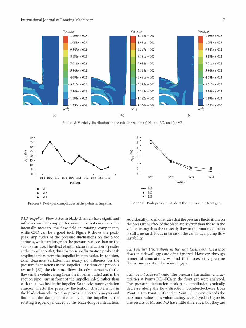
International Journal of Rotating Machinery 7
Vorticity
(s−1)1.550e + 000
1.182e + 002
2.348e + 002
3.515e + 002
4.681e + 002
5.848e + 002
7.014e + 002
8.181e + 002
9.347e + 002
1.051e + 003
1.168e + 003
(a)
Vorticity
(s−1)1.550e + 000
1.182e + 002
2.348e + 002
3.515e + 002
4.681e + 002
5.848e + 002
7.014e + 002
8.181e + 002
9.347e + 002
1.051e + 003
1.168e + 003
(b)
Vorticity
(s−1)1.550e + 000
1.182e + 002
2.348e + 002
3.515e + 002
4.681e + 002
5.848e + 002
7.014e + 002
8.181e + 002
9.347e + 002
1.051e + 003
1.168e + 003
(c)
Figure 8: Vorticity distribution on the middle section: (a) M1, (b) M2, and (c) M3.
BP1 BP2 BP3 BP4 BP5 BS1 BS2 BS3 BS4 BS5Position
M1
M2
M3
0
5
10
15
20
25
30
35
40
Ap-
p(%
)
Figure 9: Peak-peak amplitudes at the points in impeller.
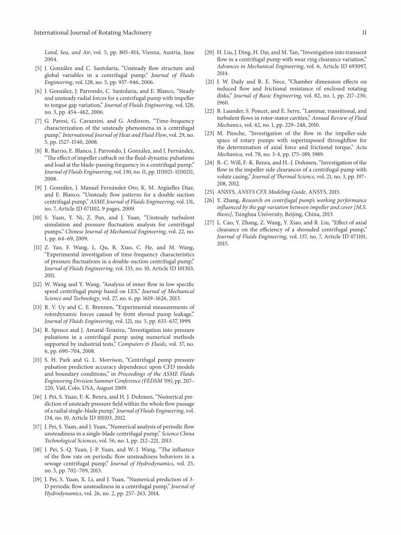
3.1.2. Impeller. Flow states in blade channels have significantinfluence on the pump performance. It is not easy to exper-imentally measure the flow field in rotating components,while CFD can be a good tool. Figure 9 shows the peak-peak amplitudes of the pressure fluctuations on the bladesurfaces, which are larger on the pressure surface than on thesuction surface.The effect of rotor-stator interaction is greaterat the impeller outlet; thus the pressure fluctuation peak-peakamplitude rises from the impeller inlet to outlet. In addition,axial clearance variation has nearly no influence on thepressure fluctuations in the impeller. Based on our previousresearch [27], the clearance flows directly interact with theflows in the volute casing (near the impeller outlet) and in thesuction pipe (just in front of the impeller inlet) rather thanwith the flows inside the impeller. So the clearance variationscarcely affects the pressure fluctuation characteristics inthe blade channels. We also process a spectral analysis andfind that the dominant frequency in the impeller is therotating frequency induced by the blade-tongue interaction.
FC1 FC2 FC3 FC4Position
M1
M2
M3
4
6
8
10
12
14
16
18
Ap-
p(%
)
Figure 10: Peak-peak amplitude at the points in the front gap.
Additionally, it demonstrates that the pressure fluctuations onthe pressure surface of the blade are severer than those in thevolute casing; thus the unsteady flow in the rotating domainis still a research focus in terms of the centrifugal pump flowinstability.
3.2. Pressure Fluctuations in the Side Chambers. Clearanceflows in sidewall gaps are often ignored. However, throughnumerical simulations, we find that noteworthy pressurefluctuations exist in the sidewall gaps.
3.2.1. Front Sidewall Gap. The pressure fluctuation charac-teristics at Points FC1∼FC4 in the front gap were analyzed.The pressure fluctuation peak-peak amplitudes graduallydecrease along the flow direction (counterclockwise fromPoint FC1 to Point FC4) and at Point FC1 it even exceeds themaximumvalue in the volute casing, as displayed in Figure 10.The results of M1 and M3 have little difference, but they are

8 International Journal of Rotating Machinery
Cp
−0.115
−0.015
0.085
0.185
0.285
0.384
0.484
0.584
0.684
0.784
0.884
FC1
FC3
FC2 FC4
(a)
Cp
−0.115
−0.015
0.085
0.185
0.285
0.384
0.484
0.584
0.684
0.784
0.884
(b)
Cp
−0.115
−0.015
0.085
0.185
0.285
0.384
0.484
0.584
0.684
0.784
0.884
(c)
Figure 11: Pressure coefficient distribution on one section of the front gap at the last timestep: (a) M1, (b) M2, and (c) M3.
Table 4: Comparison of the dominant frequencies at the points inthe front gap.
% M1 M2 M3𝑓𝑑/𝑓𝑛 𝑓𝑑/𝑓𝑛 𝑓𝑑/𝑓𝑛
FC1 3 3 3FC2 3 3 3FC3 9 9 9FC4 1/6 9 3𝑓𝑑 is the dominant frequency.
slightly larger than that of M2. Thus the pressure fluctuationintensity does not monotonously go up or down with theincrease of 𝑐𝑓.
The dominant frequencies of the pressure fluctuationsin the front gap are listed in Table 4. In each model, thedominate frequencies are not totally the same for the fourpoints; the dominant frequencies at Point FC4 are alsodifferent for the three models. The clearance flow in the frontgap is disturbed by the rotating component.The blade passing
frequency (3𝑓𝑛) dominates the pressure fluctuation in mostregion, while the back-blade passing frequency (9𝑓𝑛) playsa more important role at some lower regions. At Point FC4in M1, there even exists a frequency of 1/6𝑓𝑛 which may berelated to the combined effect of the impeller blades and backblades. Consider the complexity of the flow states in the frontgap.
Figure 11 displays the pressure coefficient distributionon the section where Points FC1∼FC4 locate. The pressurecoefficient is defined as 𝐶𝑝 = 2(𝑝 − 𝑝inlet)/(𝜌𝑢
22), where
𝑝inlet is the area-averaged pressure at the pump inlet and 𝑢2 isthe velocity at the impeller outlet. The pressure patterns lookglobally similar for the threemodels: the pressure distributionis not circumferentially uniform with evidently higher valuesin the top, which confirms the effect of the uneven flows inthe volute casing. In addition, as 𝑐𝑓 increases, the pressurelevel slightly drops. In each model, 𝐶𝑝 decreases from FC1to FC4 which is consistent with the corresponding pressurefluctuation peak-peak amplitude distribution feature. It indi-cates that the pressure at the top region is not onlywith highervalues but also fluctuating more greatly.

International Journal of Rotating Machinery 9
BC1 BC2 BC3 BC4Position
M1
M2
M3
68101214161820222426
Ap-
p(%
)
Figure 12: Peak-peak amplitudes at the points in the back sidewallgap.
3.2.2. Back Sidewall Gap. The pressure fluctuations in theback sidewall gap evidently differ from those in the front gap.As shown in Figure 12, inM1 the peak-peak amplitudes of thepressure fluctuations at the four points in the back sidewallgap are similar to those in the front gap, while in M2 and M3the peak-peak amplitudes aremuch higher and slightly undu-late along the flow direction (from Point BC1 to Point BC4).
A frequency spectrum analysis indicates that the fourpoints in the back sidewall gap of each model have the samefrequency components. We take Point BC1 as an example toillustrate the effect of the axial clearance variation. Figure 13shows the corresponding frequency spectrum. In M1 thedominant frequency is the blade passing frequency, while inM2 andM3 the dominant frequency is the rotating frequency.Due to the viscous force, the fluid in the back sidewall gapflows with the rotating back shroud. The decreasing backclearance strengthens the viscous effect; thus the pressurefluctuation is weaker in M1. For M2 and M3, the flow fieldsare relatively symmetric owing to the smaller back clearance,and the rotating back shroud contributes to the dominantfrequency (i.e., the rotating frequency). However, inM1 thereis more mass transfer between the back sidewall gap and themain flow domain; thus the pressure wave dominated by theblade passing frequency propagates to the back sidewall gap.
Figure 14 displays the pressure coefficient distributionon the section where Points BC1∼BC4 locate. Compared tothe pressure filed in the front gap, the pressure in the backsidewall gap distributes more evenly along the circumfer-ential direction, and it gradually increases with the radius.Agreeing with the explanation in the last paragraph, thepressure presents more uneven pattern in M1 due to a biggerdistance from the back shroud.
To sum up, the unsteady flow in the entire flow passageof the centrifugal pump is strongly associated with the rotor-stator interaction. The blade-tongue interaction is the mainsource of the pressure fluctuations in the main domains.Meanwhile, the front shroud, back shroud, and back bladesthat rotate with the impeller make the fluid in the sidewallgaps rotate at some degree, which may interact with the mainflow. Flow states in the sidewall gaps are sensitive to the axial
0 10 20 30 40 50 60 70
f/fn
M3
M2
M10123456789
A(%
)
Figure 13: Frequency spectrum of the pressure fluctuations at PointBC1.
clearance size. A variation of the axial clearance affects theunsteady flow characteristics in the sidewall gaps and changesthe level of the interaction between the clearance flow andthe main flow, which leads to different pressure fluctuationfrequencies. Flows in the impeller have no direct contact withclearance flows; thus the pressure fluctuation characteristicsin the blade channels are not obviously affected by theaxial clearance variation. It is meaningful to investigate theunsteady flow characteristics and the origin of the pressurefluctuations by doing numerical simulations for the entireflow passage of a centrifugal pump.
4. Conclusions
In this paper, unsteady numerical simulations were con-ducted in the design condition for a centrifugal pump withthree axial clearance sizes, and the influence of axial clearancevariation on the pressure fluctuation characteristics wasanalyzed for each flow domain. The numerical results ofpump performance and pressure fluctuations with differentaxial clearance sizes all agree well with the experimentalresults. Through spectral analysis for several key points, wefind that the axial clearance variation affects the pressure fluc-tuation characteristics in different flow domains by differentdegrees. Within the entire flow passage, the most intensivepressure fluctuation occurs at the blade pressure surface,which comes from the blade-tongue interaction, and it isalmost not influenced by the axial clearance variation. Therange of pressure fluctuation peak-peak amplitudes in thevolute casing and in the sidewall gaps is mostly similar, butthe maximum amplitude in the sidewall gaps is larger thanthat in the volute casing. Axial clearance sizes certainly affectthe pressure fluctuation characteristics around the tongueand its effect is embodied in the low frequencies. Pressurefluctuation peak-peak amplitudes in the sidewall gaps do notchange monotonously with the increase of the axial clearancesize. In the front gap, the dominant frequency is not thesame value for the four points in each model and also for thesame point in different models. In the back sidewall gap, thelargest back axial clearance leads to a much smaller pressurefluctuation which is related to viscous force from the rotating

10 International Journal of Rotating Machinery
BC1
BC3
BC2 BC4
0.534
0.569
0.604
0.639
0.674
0.709
0.745
0.780
0.815
0.850
0.885
Cp
(a)0.534
0.569
0.604
0.639
0.674
0.709
0.745
0.780
0.815
0.850
0.885
Cp
(b)
0.534
0.569
0.604
0.639
0.674
0.709
0.745
0.780
0.815
0.850
0.885
Cp
(c)
Figure 14: Pressure coefficient distribution on one section of the back sidewall gap at the last timestep: (a) M1, (b) M2, and (c) M3.
back shroud. Overall, clearance flows cannot be ignored andthe axial clearance size has a certain influence on the pressurefluctuation characteristics in main flow domains as well as insidewall gaps. The influence of the axial clearance on bothpump performance and unsteady flow characteristics shouldbe comprehensively considered in the hydraulic design ofcentrifugal pumps.
Competing Interests
The authors declared that there are no competing interestsrelated to this paper.
Acknowledgments
The authors acknowledge the financial support given bythe State Key Program of National Science of China (Grantno. 51439002), Special Funds for Marine Renewable EnergyProjects (Grant no. GHME2012GC02), and State Key
Laboratory of Hydroscience and Engineering (Grant no.2014-KY-05).
References
[1] R. Dong, S. Chu, and J. Katz, “Effect of modification to tongueand impeller geometry on unsteady flow, pressure fluctuations,and noise in a centrifugal pump,” Journal of Turbomachinery,vol. 119, no. 3, pp. 506–515, 1997.
[2] J. Gonzalez, J. Fernandez, E. Blanco, and C. Santolaria, “Numer-ical simulation of the dynamic effects due to impeller-voluteinteraction in a centrifugal pump,” Journal of Fluids Engineering,vol. 124, no. 2, pp. 348–355, 2002.
[3] J. L. Parrondo-Gayo, J. Gonzalez-Perez, and J. Fernandez-Francos, “The effect of the operating point on the pressurefluctuations at the blade passage frequency in the volute of acentrifugal pump,” Journal of Fluids Engineering, vol. 124, no. 3,pp. 784–790, 2002.
[4] M. Kitano, “Numerical study of unsteady flow in a centrifugalpump,” in Proceedings of the ASME Turbo Expo 2004: Power for
International Journal of Rotating Machinery 11
Land, Sea, and Air, vol. 5, pp. 805–814, Vienna, Austria, June2004.
[5] J. Gonzalez and C. Santolaria, “Unsteady flow structure andglobal variables in a centrifugal pump,” Journal of FluidsEngineering, vol. 128, no. 5, pp. 937–946, 2006.
[6] J. Gonzalez, J. Parrondo, C. Santolaria, and E. Blanco, “Steadyand unsteady radial forces for a centrifugal pump with impellerto tongue gap variation,” Journal of Fluids Engineering, vol. 128,no. 3, pp. 454–462, 2006.
[7] G. Pavesi, G. Cavazzini, and G. Ardizzon, “Time-frequencycharacterization of the unsteady phenomena in a centrifugalpump,” International Journal of Heat and Fluid Flow, vol. 29, no.5, pp. 1527–1540, 2008.
[8] R. Barrio, E. Blanco, J. Parrondo, J. Gonzalez, and J. Fernandez,“The effect of impeller cutback on the fluid-dynamic pulsationsand load at the blade-passing frequency in a centrifugal pump,”Journal of Fluids Engineering, vol. 130, no. 11, pp. 1111021–11110211,2008.
[9] J. Gonzalez, J. Manuel Fernandez Oro, K. M. Arguelles Dıaz,and E. Blanco, “Unsteady flow patterns for a double suctioncentrifugal pump,” ASME Journal of Fluids Engineering, vol. 131,no. 7, Article ID 071102, 9 pages, 2009.
[10] S. Yuan, Y. Ni, Z. Pan, and J. Yuan, “Unsteady turbulentsimulation and pressure fluctuation analysis for centrifugalpumps,” Chinese Journal of Mechanical Engineering, vol. 22, no.1, pp. 64–69, 2009.
[11] Z. Yao, F. Wang, L. Qu, R. Xiao, C. He, and M. Wang,“Experimental investigation of time-frequency characteristicsof pressure fluctuations in a double-suction centrifugal pump,”Journal of Fluids Engineering, vol. 133, no. 10, Article ID 101303,2011.
[12] W. Wang and Y. Wang, “Analysis of inner flow in low specificspeed centrifugal pump based on LES,” Journal of MechanicalScience and Technology, vol. 27, no. 6, pp. 1619–1626, 2013.
[13] R. V. Uy and C. E. Brennen, “Experimental measurements ofrotordynamic forces caused by front shroud pump leakage,”Journal of Fluids Engineering, vol. 121, no. 3, pp. 633–637, 1999.
[14] R. Spence and J. Amaral-Teixeira, “Investigation into pressurepulsations in a centrifugal pump using numerical methodssupported by industrial tests,” Computers & Fluids, vol. 37, no.6, pp. 690–704, 2008.
[15] S. H. Park and G. L. Morrison, “Centrifugal pump pressurepulsation prediction accuracy dependence upon CFD modelsand boundary conditions,” in Proceedings of the ASME FluidsEngineeringDivision SummerConference (FEDSM ’09), pp. 207–220, Vail, Colo, USA, August 2009.
[16] J. Pei, S. Yuan, F.-K. Benra, and H. J. Dohmen, “Numerical pre-diction of unsteady pressure field within the whole flow passageof a radial single-blade pump,” Journal of Fluids Engineering, vol.134, no. 10, Article ID 101103, 2012.
[17] J. Pei, S. Yuan, and J. Yuan, “Numerical analysis of periodic flowunsteadiness in a single-blade centrifugal pump,” Science ChinaTechnological Sciences, vol. 56, no. 1, pp. 212–221, 2013.
[18] J. Pei, S.-Q. Yuan, J.-P. Yuan, and W.-J. Wang, “The influenceof the flow rate on periodic flow unsteadiness behaviors in asewage centrifugal pump,” Journal of Hydrodynamics, vol. 25,no. 5, pp. 702–709, 2013.
[19] J. Pei, S. Yuan, X. Li, and J. Yuan, “Numerical prediction of 3-D periodic flow unsteadiness in a centrifugal pump,” Journal ofHydrodynamics, vol. 26, no. 2, pp. 257–263, 2014.
[20] H. Liu, J. Ding, H. Dai, andM. Tan, “Investigation into transientflow in a centrifugal pump with wear ring clearance variation,”Advances in Mechanical Engineering, vol. 6, Article ID 693097,2014.
[21] J. W. Daily and R. E. Nece, “Chamber dimension effects oninduced flow and frictional resistance of enclosed rotatingdisks,” Journal of Basic Engineering, vol. 82, no. 1, pp. 217–230,1960.
[22] B. Launder, S. Poncet, and E. Serre, “Laminar, transitional, andturbulent flows in rotor-stator cavities,” Annual Review of FluidMechanics, vol. 42, no. 1, pp. 229–248, 2010.
[23] M. Piesche, “Investigation of the flow in the impeller-sidespace of rotary pumps with superimposed throughflow forthe determination of axial force and frictional torque,” ActaMechanica, vol. 78, no. 3-4, pp. 175–189, 1989.
[24] B.-C.Will, F.-K. Benra, and H.-J. Dohmen, “Investigation of theflow in the impeller side clearances of a centrifugal pump withvolute casing,” Journal ofThermal Science, vol. 21, no. 3, pp. 197–208, 2012.
[25] ANSYS, ANSYS CFX Modeling Guide, ANSYS, 2015.[26] Y. Zhang, Research on centrifugal pump’s working performance
influenced by the gap variation between impeller and cover [M.S.thesis], Tsinghua University, Beijing, China, 2013.
[27] L. Cao, Y. Zhang, Z. Wang, Y. Xiao, and R. Liu, “Effect of axialclearance on the efficiency of a shrouded centrifugal pump,”Journal of Fluids Engineering, vol. 137, no. 7, Article ID 071101,2015.

International Journal of
AerospaceEngineeringHindawi Publishing Corporationhttp://www.hindawi.com Volume 2014
RoboticsJournal of
Hindawi Publishing Corporationhttp://www.hindawi.com Volume 2014
Hindawi Publishing Corporationhttp://www.hindawi.com Volume 2014
Active and Passive Electronic Components
Control Scienceand Engineering
Journal of
Hindawi Publishing Corporationhttp://www.hindawi.com Volume 2014
International Journal of
RotatingMachinery
Hindawi Publishing Corporationhttp://www.hindawi.com Volume 2014
Hindawi Publishing Corporation http://www.hindawi.com
Journal ofEngineeringVolume 2014
Submit your manuscripts athttp://www.hindawi.com
VLSI Design
Hindawi Publishing Corporationhttp://www.hindawi.com Volume 2014
Hindawi Publishing Corporationhttp://www.hindawi.com Volume 2014
Shock and Vibration
Hindawi Publishing Corporationhttp://www.hindawi.com Volume 2014
Civil EngineeringAdvances in
Acoustics and VibrationAdvances in
Hindawi Publishing Corporationhttp://www.hindawi.com Volume 2014
Hindawi Publishing Corporationhttp://www.hindawi.com Volume 2014
Electrical and Computer Engineering
Journal of
Advances inOptoElectronics
Hindawi Publishing Corporation http://www.hindawi.com
Volume 2014
The Scientific World JournalHindawi Publishing Corporation http://www.hindawi.com Volume 2014
SensorsJournal of
Hindawi Publishing Corporationhttp://www.hindawi.com Volume 2014
Modelling & Simulation in EngineeringHindawi Publishing Corporation http://www.hindawi.com Volume 2014
Hindawi Publishing Corporationhttp://www.hindawi.com Volume 2014
Chemical EngineeringInternational Journal of Antennas and
Propagation
International Journal of
Hindawi Publishing Corporationhttp://www.hindawi.com Volume 2014
Hindawi Publishing Corporationhttp://www.hindawi.com Volume 2014
Navigation and Observation
International Journal of
Hindawi Publishing Corporationhttp://www.hindawi.com Volume 2014
DistributedSensor Networks
International Journal of