MultiView 1000™ Product Presentation Nanonics MultiView 1000™

Lecture#4
RES112E– COMPUTERAIDEDTECHNICALDRAWING2015@ITU
MULTIVIEWPROJECTION
ThisweekYou will learn multi-view projection.The steps to follow are:◦Projections (ISO-E & ISO-A)◦Multi-view drawings◦Views (Basic, Auxiliary, Detailed etc.)◦Sketching 2-D Geometry◦Assignment # 3
RES112E– COMPUTERAIDEDTECHNICALDRAWING2015@ITU

PrinciplesORTHOGRAPHICPROJECTION
RES112E– COMPUTERAIDEDTECHNICALDRAWING2015@ITU

RES112E– COMPUTERAIDEDTECHNICALDRAWING2015@ITU

Projections
RES112E– COMPUTERAIDEDTECHNICALDRAWING2015@ITU
Multi-viewprojection (Orthographicprojections):aredrawnasmultiviewdrawings,whichshowflatrepresentationsofprincipalviewsoftheobject.
Perspectiveprojections aredrawingswhichattempttoreplicatewhatthehumaneyeactuallyseeswhenitviewsanobject.
AxonometricProjections: arethree-dimensionaldrawings,andareofthreedifferentvarieties:Isometric,DimetricandTrimetric.
ObliqueProjections: actuallyshowthefullsizeofoneview.
ParallelProjection isatypeofprojectionwherethelineofsightorprojectorsareparallelandareperpendiculartothepictureplanes.

Theattributesofprojectionmethods
RES112E– COMPUTERAIDEDTECHNICALDRAWING2015@ITU

Whatisorthographic?
RES112E– COMPUTERAIDEDTECHNICALDRAWING2015@ITU
– theplaneuponwhichthefrontalviewisprojected
– theplaneuponwhichthetopviewisprojected
– theplaneuponwhichthesideviewisprojected
Orthographic projection is a method of producing a numberof separate two-dimensional inter-related views, which aremutually at right angles to each other. Using this projection,even the most complex shape can be fully described.

ThewayofcommunicatingideasthateverybodyunderstoodwasaproblemthatfacedGaspardMonge(asanEngineerintheFrenchMilitary).
Hedevisedasystemthatcouldbeusedtocommunicateanobjecttoanyoneacrosstheworld.
Historyoforthographic
RES112E– COMPUTERAIDEDTECHNICALDRAWING2015@ITU
ThissystemiscalledOrthographicProjectionandwasquicklyadoptedbyarmyengineers.

OrthographicProjections
RES112E– COMPUTERAIDEDTECHNICALDRAWING2015@ITU
Orthographic projections aredrawings where the projectors,theobserverorstationpointremainparalleltoeachotherandperpendiculartotheplaneofprojection.
Orthographic projections arefurther subdivided into axonometricprojectionsandmulti-viewprojections.
Effectiveintechnicalrepresentationofobjects.

Projectionsystems
RES112E– COMPUTERAIDEDTECHNICALDRAWING2015@ITU

Orthographicprojection
RES112E– COMPUTERAIDEDTECHNICALDRAWING2015@ITU

Orthographicprojection
RES112E– COMPUTERAIDEDTECHNICALDRAWING2015@ITU

ProjectionSymbols
RES112E– COMPUTERAIDEDTECHNICALDRAWING2015@ITU

RES112E– COMPUTERAIDEDTECHNICALDRAWING2015@ITU

MiterlineOrthographicProjectionutilizesaMiterLinedrawnat45degreeswhichenablesinformationtobeprojectedfromthetopviewtothesideview,andfromthesideviewtothetopview.
RES112E– COMPUTERAIDEDTECHNICALDRAWING2015@ITU

PrinciplesMUTLIVIEWDRAWING
RES112E– COMPUTERAIDEDTECHNICALDRAWING2015@ITU

Whatismultiview?
RES112E– COMPUTERAIDEDTECHNICALDRAWING2015@ITU
InvolvesvisualizationandimplementationoAbilitytoseeanobjectclearlyinthemind’seye.oProcess(steps)ofdrawingtheobject
Anothernamefororthographicprojectionismulti-viewdrawing.Multi-view (multiplanar) projection is a method bywhich the exact shape of an object can berepresented by two or more separate viewsproduced on projection planes that are at rightangles to each other.

oMultiview drawing is classified as a parallel projectiontechnique, because the lines of sight used to view theobject are parallel
oA system that allows you to make a two-dimensionaldrawing of a three-dimensional object.
oThe images are called “views“.
Multiviewdrawing
RES112E– COMPUTERAIDEDTECHNICALDRAWING2015@ITU
FRONTL.SIDE R.SIDE
TOP
BOTTOM
BACK

Thereare9differenttypesofviewsusedforengineeringdrawings,namely
Basicviews
RES112E– COMPUTERAIDEDTECHNICALDRAWING2015@ITU
Auxiliaryview
DetailedviewBottomview
Rearview
Frontview
Topview Sectionview
Left-sideview
Right-sideview

RES112E– COMPUTERAIDEDTECHNICALDRAWING2015@ITU

AlphabetofLines
RES112E– COMPUTERAIDEDTECHNICALDRAWING2015@ITU

Linetypes
RES112E– COMPUTERAIDEDTECHNICALDRAWING2015@ITU
You will draw the centerlines for the circle. Center linesfor holes must be included in all views. A centermark andfour lines extending beyond the four quadrant points areused.
Center Lines
Thecenterlineisusedto:o Showtheaxisofsymmetryofafeatureorparto Indicateapathofmotiono Showthelocationforboltcirclesorother
circularpatterns

Linetypes
RES112E– COMPUTERAIDEDTECHNICALDRAWING2015@ITU
You should follow at least three general practices whendrawing hidden lines to help prevent confusion and tomake the drawing easier to read.
Hidden Lines
o clearly show intersections using intersecting linesegments
o clearly show corners, using intersecting linesegments
o leave a noticeable gap between aligned continuouslines and hidden lines

Adjustinglinteypescale
RES112E– COMPUTERAIDEDTECHNICALDRAWING2015@ITU
LTSCALE determines the relative length of dashesin linetypes such as hidden and center lines.Setting a linetype scale ensures that the lines youdraw are represented properly on the screen andwhen the drawing is plotted.
Command : LTSCALEEnter new linetype scale factor <1.000> : 0.5Regenerating model.Command :

Linetypes
RES112E– COMPUTERAIDEDTECHNICALDRAWING2015@ITU
Widthofslotprojectedintotopview

LinePrecedence
RES112E– COMPUTERAIDEDTECHNICALDRAWING2015@ITU
Different types of lines often align with each other withinthe same view.
Theruleisthatcontinuouslinestakeprecedenceoverhiddenlines,andhiddenlinestakeprecedenceovercenterlines.
Ifyoushowtheshortendsegmentswereacenterlinewouldextend,besuretoleaveagap.

Theorderofprecedenceoflines
RES112E– COMPUTERAIDEDTECHNICALDRAWING2015@ITU
Visible object lines
Hiddenlines
Centerlineorcuttingplaneline
Crosshatch/sectionlines
Dimensionandextensionlines
Breaklines

LinePrecedence
RES112E– COMPUTERAIDEDTECHNICALDRAWING2015@ITU
Continuouslineoverahiddenline
Hiddenlineoveracenterline
Continuouslineoverahiddenline

RES112E– COMPUTERAIDEDTECHNICALDRAWING2015@ITU
You will learn creating section view. The stepsto follow are:◦Cutting plane◦Kind of sectional views (full, half, etc.)◦Section line symbols◦Conventional practice◦Assembly sections◦Creating section views in AutoCAD◦Assignment # 4
Thefollowingweek

TeamMeetingDURATION1HOUR
RES112E– COMPUTERAIDEDTECHNICALDRAWING2015@ITU
RES112E– COMPUTERAIDEDTECHNICALDRAWING2015@ITU
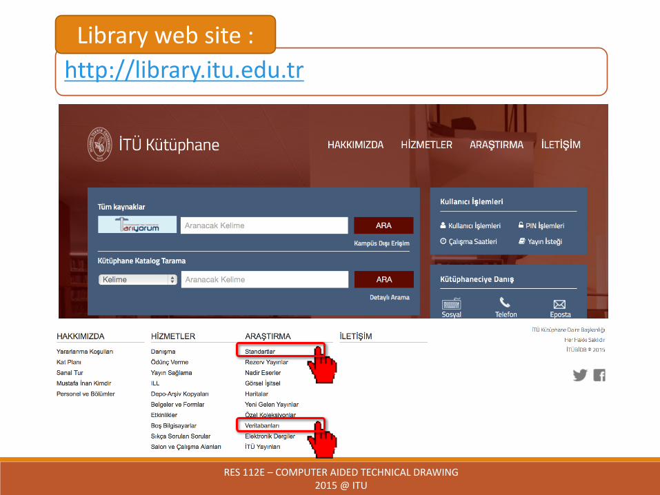
http://library.itu.edu.trLibrarywebsite:

RES112E– COMPUTERAIDEDTECHNICALDRAWING2015@ITU
https://intweb.tse.org.tr/Standard/Standard/StandardAra.aspxTSEwebsite:

RES112E– COMPUTERAIDEDTECHNICALDRAWING2015@ITU
http://online.tpe.gov.tr/EPATENT/servlet/EPreSearchRequestManagerTPEwebsite:

RES112E– COMPUTERAIDEDTECHNICALDRAWING2015@ITU
http://www.epo.org/index.htmlEuropeanPatentOfficewebsite:

Meetingminute
RES112E– COMPUTERAIDEDTECHNICALDRAWING2015@ITU

RES112E– COMPUTERAIDEDTECHNICALDRAWING2015@ITU
Assignment#3
Page
Figure
You will sketch and complete viewsSubmit the assignment on timeUpload file into NINOVA