Republic Of Iraq Ministry Of Electricity General...
26
7-4-2015 Republic Of Iraq Ministry Of Electricity General Directorate of Electrical Power Transmission Upper Euphrates Region Tender /UE/2015 Reconstruction of Ramadi east substation 132/33/11KV &Tikrit South substation 132/33/11KV Design, supply of equipment & materials, training -1-
Transcript of Republic Of Iraq Ministry Of Electricity General...
7-4-2015
Republic Of Iraq
Ministry Of Electricity
General Directorate of Electrical Power
Transmission Upper Euphrates Region
Tender /UE/2015
Reconstruction of Ramadi east substation 132/33/11KV
&Tikrit South substation 132/33/11KV
Design, supply of equipment & materials, training
-1-
7-4-2015
Reconstruction of Ramadi east substation 132/33/11KV
Ramadi East substation location
Iraq-AL-Anbar governorate
Ramadi town
-2-
7-4-2015
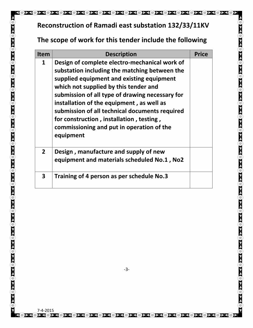
Reconstruction of Ramadi east substation 132/33/11KV
The scope of work for this tender include the following
Item Description Price
1 Design of complete electro-mechanical work of substation including the matching between the supplied equipment and existing equipment which not supplied by this tender and submission of all type of drawing necessary for installation of the equipment , as well as submission of all technical documents required for construction , installation , testing , commissioning and put in operation of the equipment
2 Design , manufacture and supply of new equipment and materials scheduled No.1 , No2
3 Training of 4 person as per schedule No.3
-3-
7-4-2015
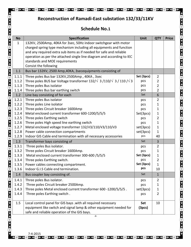
Reconstruction of Ramadi-East substation 132/33/11KV
Schedule No.1
No Specification Unit QTY Price
1
132KV, 2500Amp, 40KA for 3sec, 50Hz indoor switchgear with motor charged spring type mechanism including all equipments and function and any required extra sub items as if needed for safe and reliable operation as per the attached single line diagram and according to IEC standards and MOE requirements Consist the following
1.1 Bus bar 132KV, 2500 Amp,40KA, 3secequipments consisting of
1.1.1 1.1.2 1.1.3 1.1.4
Three poles Bus bar 132KV,2500Amp , 40KA , 3sec Three poles BUS bar Voltage transformer 132/√ 3 /110/√ 3 / 110 /√ 3 Three poles Bus isolator Three poles Bus bar earthing switch
Set (3pcs)
pcs pcs pcs
2 2 2 2
1.2 Line bay consisting of for each Set 6
1.2.1 1.2.2 1.2.3 1.2.4 1.2.5 1.2.6 1.2.7 1.2.8 1.2.9
Three poles Bus isolator Three poles Line isolator Three poles Circuit breaker 1600Amp Metal enclosed current transformer 600-1200/5/5/5 Three poles Earthing switch Three poles High speed line earthing switch Metal enclosed voltage transformer 132/√3/110/√3/110/√3 Power cable connection compartments Indoor GIS Cable end termination with all necessary accessories
pcs pcs pcs
Set(3pcs) pcs pcs
set(3pcs) set(3pcs)
pcs
2 1 1 1 2 1 1 1
40
1.3 Transformer bays consisting of Set 3
1.3.1 1.3.2 1.3.3 1.3.4 1.3.5 1.3.6
Three poles Bus isolator. Three poles Circuit breaker 1600Amp. Metal enclosed current transformer 300-600 /5/5/5 Three poles Earthing switch. Power cables connecting compartment. Indoor G.I.S Cable end termination.
pcs pcs
Set (3pcs)
pcs Set (3pcs)
pcs
2 1 1 2 1
10
1.4 Bus coupler bay consisting of. Set 1
1.4.1 1.4.2 1.4.3 1.4.4
Three poles Bus isolator. Three poles Circuit breaker 2500Amp. Three poles Metal enclosed current transformer 600 -1200/5/5/5 . Three poles Earthing switch .
pcs pcs
set(3pcs) pcs
2 1 1 2
1.5 Local control panel for GIS bays .with all required necessary equipment like switch and signal lamp & other equipment needed for safe and reliable operation of the GIS bays.
Set (3pcs)
10
-4-
7-4-2015
No Specification Unit QTY Price
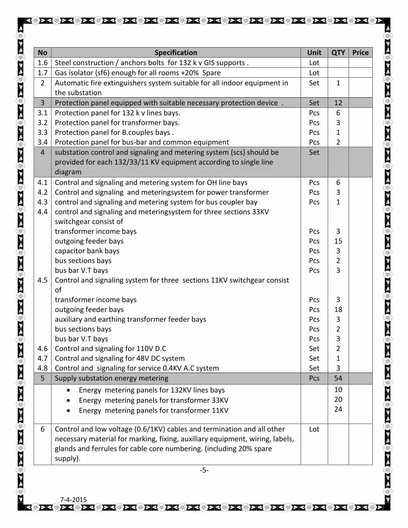
1.6 Steel construction / anchors bolts for 132 k v GIS supports . Lot
1.7 Gas isolator (sf6) enough for all rooms +20% Spare Lot
2 Automatic fire extinguishers system suitable for all indoor equipment in the substation
Set 1
3 Protection panel equipped with suitable necessary protection device . Set 12
3.1 3.2 3.3 3.4
Protection panel for 132 k v lines bays. Protection panel for transformer bays. Protection panel for B.couples bays . Protection panel for bus-bar and common equipment
Pcs Pcs Pcs Pcs
6 3 1 2
4
substation control and signaling and metering system (scs) should be provided for each 132/33/11 KV equipment according to single line diagram
Set
4.1 4.2 4.3 4.4 4.5 4.6 4.7 4.8
Control and signaling and metering system for OH line bays Control and signaling and meteringsystem for power transformer control and signaling and metering system for bus coupler bay control and signaling and meteringsystem for three sections 33KV switchgear consist of transformer income bays outgoing feeder bays capacitor bank bays bus sections bays bus bar V.T bays Control and signaling system for three sections 11KV switchgear consist of transformer income bays outgoing feeder bays auxiliary and earthing transformer feeder bays bus sections bays bus bar V.T bays Control and signaling for 110V D.C Control and signaling for 48V DC system Control and signaling for service 0.4KV A.C system
Pcs Pcs Pcs
Pcs Pcs Pcs Pcs Pcs
Pcs Pcs Pcs Pcs Pcs Set Set Set
6 3 1
3 15 3 2 3
3 18 3 2 3 2 1 3
5 Supply substation energy metering Pcs 54
Energy metering panels for 132KV lines bays
Energy metering panels for transformer 33KV
Energy metering panels for transformer 11KV
10 20 24
6
Control and low voltage (0.6/1KV) cables and termination and all other necessary material for marking, fixing, auxiliary equipment, wiring, labels, glands and ferrules for cable core numbering. (including 20% spare supply).
Lot
-5-
7-4-2015
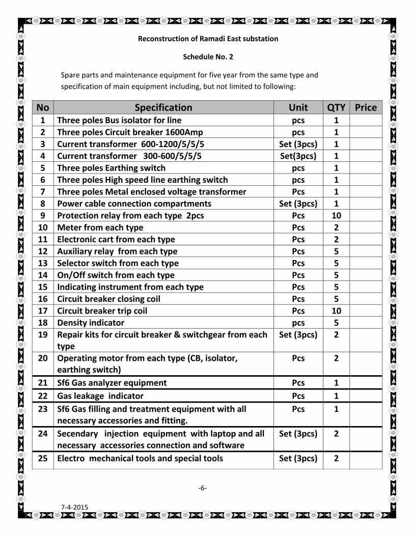
Reconstruction of Ramadi East substation
Schedule No. 2
Spare parts and maintenance equipment for five year from the same type and specification of main equipment including, but not limited to following:
No Specification Unit QTY Price 1 Three poles Bus isolator for line pcs 1
2 Three poles Circuit breaker 1600Amp pcs 1
3 Current transformer 600-1200/5/5/5 Set (3pcs) 1 4 Current transformer 300-600/5/5/5 Set(3pcs) 1
5 Three poles Earthing switch pcs 1 6 Three poles High speed line earthing switch pcs 1
7 Three poles Metal enclosed voltage transformer Pcs 1 8 Power cable connection compartments Set (3pcs) 1
9 Protection relay from each type 2pcs Pcs 10
10 Meter from each type Pcs 2 11 Electronic cart from each type Pcs 2
12 Auxiliary relay from each type Pcs 5 13 Selector switch from each type Pcs 5
14 On/Off switch from each type Pcs 5 15 Indicating instrument from each type Pcs 5
16 Circuit breaker closing coil Pcs 5
17 Circuit breaker trip coil Pcs 10 18 Density indicator pcs 5
19 Repair kits for circuit breaker & switchgear from each type
Set (3pcs) 2
20 Operating motor from each type (CB, isolator, earthing switch)
Pcs 2
21 Sf6 Gas analyzer equipment Pcs 1
22 Gas leakage indicator Pcs 1
23 Sf6 Gas filling and treatment equipment with all necessary accessories and fitting.
Pcs 1
24 Secendary injection equipment with laptop and all necessary accessories connection and software
Set (3pcs) 2
25 Electro mechanical tools and special tools Set (3pcs) 2
-6-
7-4-2015
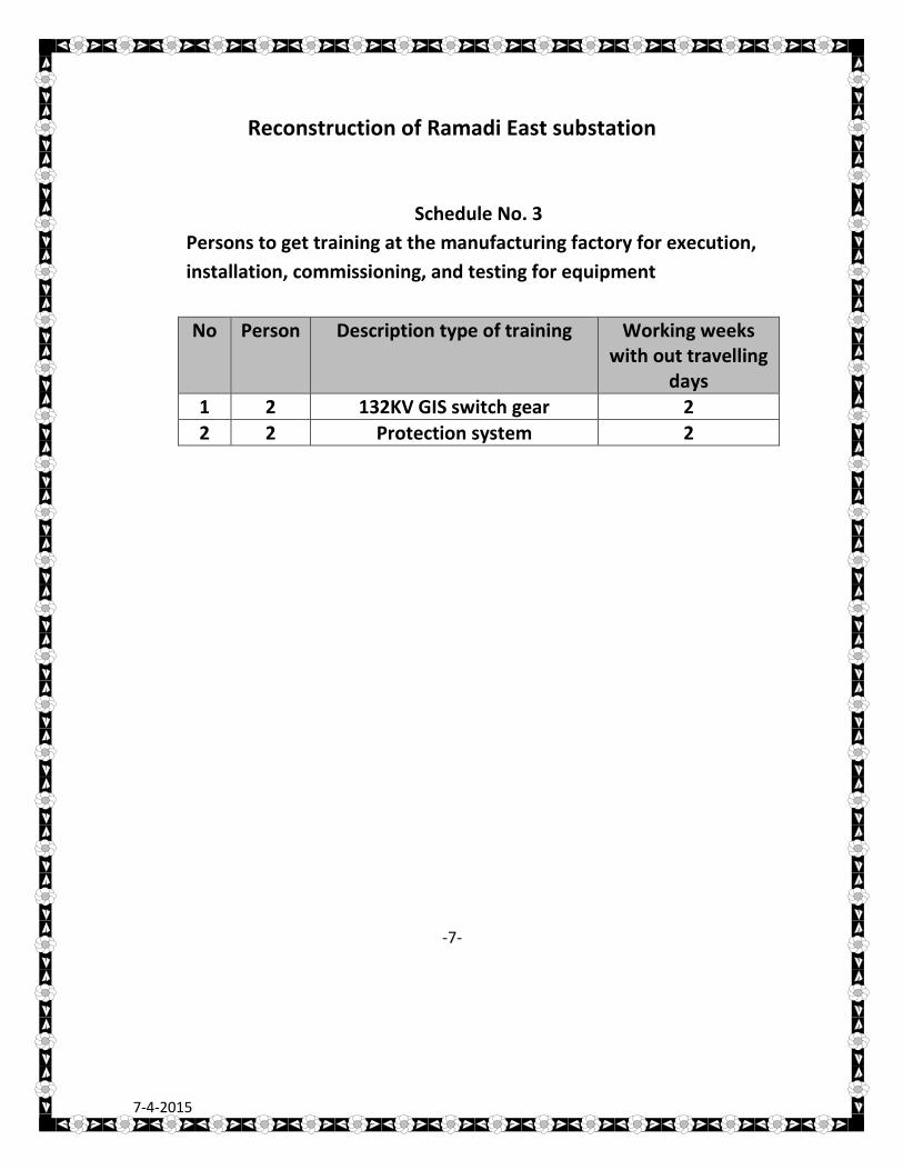
Reconstruction of Ramadi East substation
Schedule No. 3
Persons to get training at the manufacturing factory for execution,
installation, commissioning, and testing for equipment
No Person Description type of training Working weeks with out travelling
days 1 2 132KV GIS switch gear 2
2 2 Protection system 2
-7-
7-4-2015
Tikrit South substation 132/33/11KV
Tikrit South substation location
IRAQ-Salah El-dein governorate
Tikrit town
-8-
7-4-2015
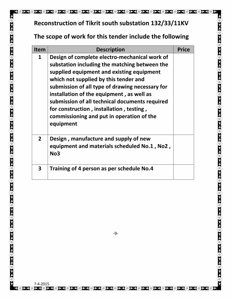
Reconstruction of Tikrit south substation 132/33/11KV
The scope of work for this tender include the following
Item Description Price
1 Design of complete electro-mechanical work of substation including the matching between the supplied equipment and existing equipment which not supplied by this tender and submission of all type of drawing necessary for installation of the equipment , as well as submission of all technical documents required for construction , installation , testing , commissioning and put in operation of the equipment
2 Design , manufacture and supply of new equipment and materials scheduled No.1 , No2 , No3
3 Training of 4 person as per schedule No.4
-9-
7-4-2015
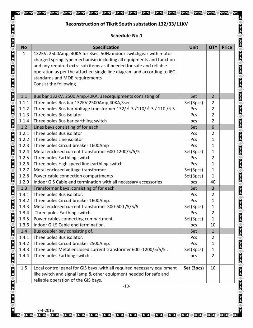
Reconstruction of Tikrit South substation 132/33/11KV
Schedule No.1
No Specification Unit QTY Price
1
132KV, 2500Amp, 40KA for 3sec, 50Hz indoor switchgear with motor charged spring type mechanism including all equipments and function and any required extra sub items as if needed for safe and reliable operation as per the attached single line diagram and according to IEC standards and MOE requirements Consist the following
1.1 Bus bar 132KV, 2500 Amp,40KA, 3secequipments consisting of Set 2
1.1.1 1.1.2 1.1.3 1.1.4
Three poles Bus bar 132KV,2500Amp,40KA,3sec Three poles Bus bar Voltage transformer 132/√ 3 /110/√ 3 / 110 /√ 3 Three poles Bus isolator Three poles Bus bar earthling switch
Set(3pcs) Pcs Pcs pcs
2 2 2 2
1.2 Lines bays consisting of for each Set 6
1.2.1 1.2.2 1.2.3 1.2.4 1.2.5 1.2.6 1.2.7 1.2.8 1.2.9
Three poles Bus isolator Three poles Line isolator Three poles Circuit breaker 1600Amp Metal enclosed current transformer 600-1200/5/5/5 Three poles Earthling switch Three poles High speed line earthling switch Metal enclosed voltage transformer Power cable connection compartments Indoor GIS Cable end termination with all necessary accessories
Pcs Pcs Pcs
Set(3pcs) Pcs Pcs
Set(3pcs) Set(3pcs)
pcs
2 1 1 1 2 1 1 1
40
1.3 Transformer bays .consisting of for each Set 3
1.3.1 1.3.2 1.3.3 1.3.4 1.3.5 1.3.6
Three poles Bus isolator. Three poles Circuit breaker 1600Amp. Metal enclosed current transformer 300-600 /5/5/5 Three poles Earthing switch. Power cables connecting compartment. Indoor G.I.S Cable end termination.
Pcs Pcs
Set(3pcs)Pcs
Set(3pcs)pcs
2 1 1 2 1
10
1.4 Bus coupler bay consisting of. Set 1
1.4.1 1.4.2 1.4.3 1.4.4
Three poles Bus isolator. Three poles Circuit breaker 2500Amp. Three poles Metal enclosed current transformer 600 -1200/5/5/5 . Three poles Earthing switch .
Pcs Pcs
Set(3pcs) pcs
2 1 1 2
1.5 Local control panel for GIS bays .with all required necessary equipment like switch and signal lamp & other equipment needed for safe and reliable operation of the GIS bays.
Set (3pcs) 10
-10-
7-4-2015
No Specification Unit QTY Price
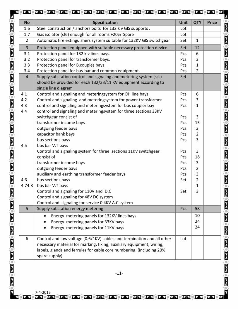
1.6 Steel construction / anchors bolts for 132 k v GIS supports . Lot
1.7 Gas isolator (sf6) enough for all rooms +20% Spare Lot
2 Automatic fire extinguishers system suitable for 132KV GIS switchgear Set 1
3 Protection panel equipped with suitable necessary protection device . Set 12
3.1 3.2 3.3 3.4
Protection panel for 132 k v lines bays. Protection panel for transformer bays. Protection panel for B.couples bays . Protection panel for bus-bar and common equipment.
Pcs Pcs Pcs Pcs
6 3 1 2
4
Supply substation control and signaling and metering system (scs) should be provided for each 132/33/11 KV equipment according to single line diagram
Set
4.1 4.2 4.3 4.4 4.5 4.6 4.74.8
Control and signaling and meteringsystem for OH line bays Control and signaling and meteringsystem for power transformer control and signaling and meteringsystem for bus coupler bay control and signaling and meteringsystem for three sections 33KV switchgear consist of transformer income bays outgoing feeder bays capacitor bank bays bus sections bays bus bar V.T bays Control and signaling system for three sections 11KV switchgear consist of transformer income bays outgoing feeder bays auxiliary and earthing transformer feeder bays bus sections bays bus bar V.T bays Control and signaling for 110V and D.C Control and signaling for 48V DC system Control and signaling for service 0.4KV A.C system
Pcs Pcs Pcs
Pcs Pcs Pcs Pcs Pcs
Pcs Pcs Pcs Pcs Pcs Set
Set
6 3 1
3 15 3 2 3
3 18 3 2 3 2 1 3
5 Supply substation energy metering Pcs 58
Energy metering panels for 132KV lines bays
Energy metering panels for 33KV bays
Energy metering panels for 11KV bays
10 24 24
6
Control and low voltage (0.6/1KV) cables and termination and all other necessary material for marking, fixing, auxiliary equipment, wiring, labels, glands and ferrules for cable core numbering. (including 20% spare supply).
Lot
-11-
7-4-2015
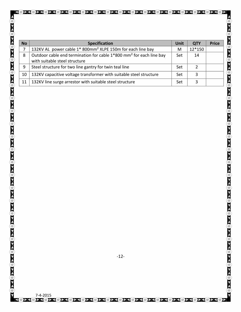
No Specification Unit QTY Price
7 132KV AL power cable 1* 800mm² XLPE 150m for each line bay M 12*150
8 Outdoor cable end termination for cable 1*800 mm² for each line bay with suitable steel structure
Set 14
9 Steel structure for two line gantry for twin teal line Set 2
10 132KV capacitive voltage transformer with suitable steel structure Set 3
11 132KV line surge arrestor with suitable steel structure Set 3
-12-
7-4-2015
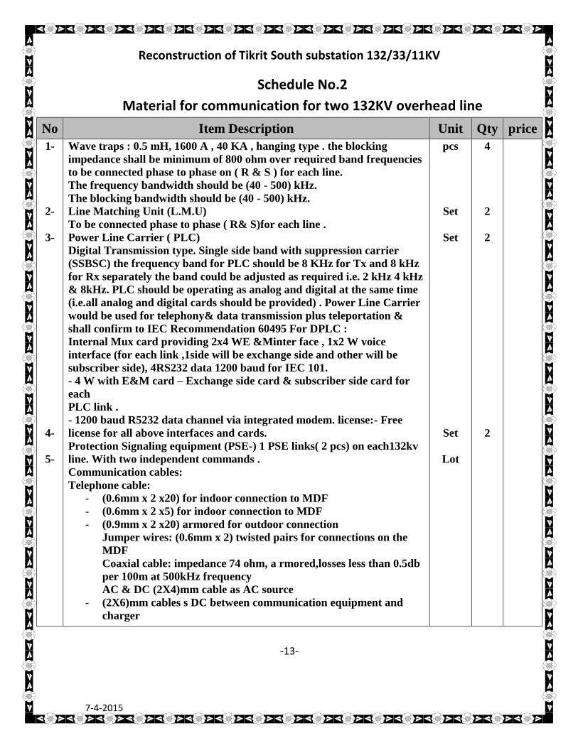
Reconstruction of Tikrit South substation 132/33/11KV
Schedule No.2
Material for communication for two 132KV overhead line
No Item Description Unit Qty price
1-
2-
3-
4-
5-
Wave traps : 0.5 mH, 1600 A , 40 KA , hanging type . the blocking
impedance shall be minimum of 800 ohm over required band frequencies
to be connected phase to phase on ( R & S ) for each line.
The frequency bandwidth should be (40 - 500) kHz.
The blocking bandwidth should be (40 - 500) kHz.
Line Matching Unit (L.M.U)
To be connected phase to phase ( R& S)for each line .
Power Line Carrier ( PLC)
Digital Transmission type. Single side band with suppression carrier
(SSBSC) the frequency band for PLC should be 8 KHz for Tx and 8 kHz
for Rx separately the band could be adjusted as required i.e. 2 kHz 4 kHz
& 8kHz. PLC should be operating as analog and digital at the same time
(i.e.all analog and digital cards should be provided) . Power Line Carrier
would be used for telephony& data transmission plus teleportation &
shall confirm to IEC Recommendation 60495 For DPLC :
Internal Mux card providing 2x4 WE &Minter face , 1x2 W voice
interface (for each link ,1side will be exchange side and other will be
subscriber side), 4RS232 data 1200 baud for IEC 101.
- 4 W with E&M card – Exchange side card & subscriber side card for
each
PLC link .
- 1200 baud R5232 data channel via integrated modem. license:- Free
license for all above interfaces and cards.
Protection Signaling equipment (PSE-) 1 PSE links( 2 pcs) on each132kv
line. With two independent commands .
Communication cables:
Telephone cable:
- (0.6mm x 2 x20) for indoor connection to MDF
- (0.6mm x 2 x5) for indoor connection to MDF
- (0.9mm x 2 x20) armored for outdoor connection
Jumper wires: (0.6mm x 2) twisted pairs for connections on the
MDF
Coaxial cable: impedance 74 ohm, a rmored,losses less than 0.5db
per 100m at 500kHz frequency
AC & DC (2X4)mm cable as AC source
- (2X6)mm cables s DC between communication equipment and
charger
pcs
Set
Set
Set
Lot
4
2
2
2
-13-
7-4-2015
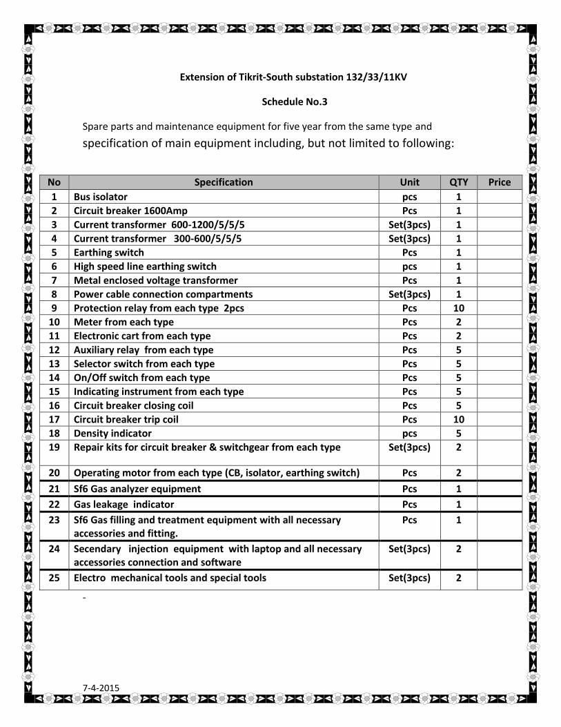
Extension of Tikrit-South substation 132/33/11KV
Schedule No.3
Spare parts and maintenance equipment for five year from the same type and
specification of main equipment including, but not limited to following:
-
No Specification Unit QTY Price
1 Bus isolator pcs 1
2 Circuit breaker 1600Amp Pcs 1
3 Current transformer 600-1200/5/5/5 Set(3pcs) 1
4 Current transformer 300-600/5/5/5 Set(3pcs) 1
5 Earthing switch Pcs 1
6 High speed line earthing switch pcs 1
7 Metal enclosed voltage transformer Pcs 1
8 Power cable connection compartments Set(3pcs) 1
9 Protection relay from each type 2pcs Pcs 10
10 Meter from each type Pcs 2
11 Electronic cart from each type Pcs 2
12 Auxiliary relay from each type Pcs 5
13 Selector switch from each type Pcs 5
14 On/Off switch from each type Pcs 5
15 Indicating instrument from each type Pcs 5
16 Circuit breaker closing coil Pcs 5
17 Circuit breaker trip coil Pcs 10
18 Density indicator pcs 5
19 Repair kits for circuit breaker & switchgear from each type Set(3pcs) 2
20 Operating motor from each type (CB, isolator, earthing switch) Pcs 2
21 Sf6 Gas analyzer equipment Pcs 1
22 Gas leakage indicator Pcs 1
23 Sf6 Gas filling and treatment equipment with all necessary accessories and fitting.
Pcs 1
24 Secendary injection equipment with laptop and all necessary accessories connection and software
Set(3pcs) 2
25 Electro mechanical tools and special tools Set(3pcs) 2
7-4-2015
-14-
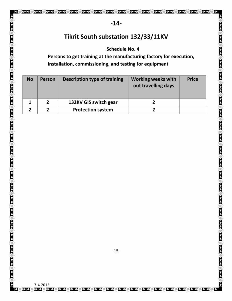
Tikrit South substation 132/33/11KV
Schedule No. 4
Persons to get training at the manufacturing factory for execution,
installation, commissioning, and testing for equipment
No Person Description type of training Working weeks with out travelling days
Price
1 2 132KV GIS switch gear 2
2 2 Protection system 2
-15-
7-4-2015
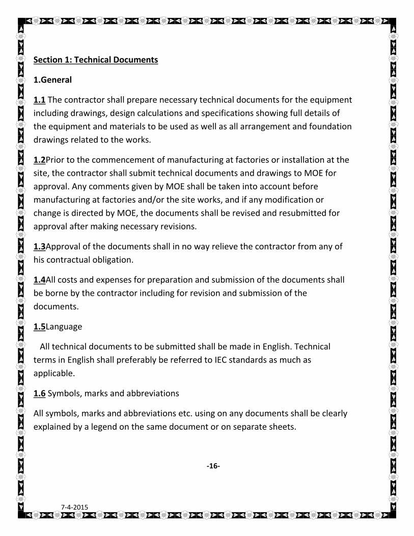
Section 1: Technical Documents
1.General
1.1 The contractor shall prepare necessary technical documents for the equipment
including drawings, design calculations and specifications showing full details of
the equipment and materials to be used as well as all arrangement and foundation
drawings related to the works.
1.2Prior to the commencement of manufacturing at factories or installation at the
site, the contractor shall submit technical documents and drawings to MOE for
approval. Any comments given by MOE shall be taken into account before
manufacturing at factories and/or the site works, and if any modification or
change is directed by MOE, the documents shall be revised and resubmitted for
approval after making necessary revisions.
1.3Approval of the documents shall in no way relieve the contractor from any of
his contractual obligation.
1.4All costs and expenses for preparation and submission of the documents shall
be borne by the contractor including for revision and submission of the
documents.
1.5Language
All technical documents to be submitted shall be made in English. Technical
terms in English shall preferably be referred to IEC standards as much as
applicable.
1.6 Symbols, marks and abbreviations
All symbols, marks and abbreviations etc. using on any documents shall be clearly
explained by a legend on the same document or on separate sheets.
-16-
7-4-2015
1.7The abbreviation and marks used for an individual device shall be identical
throughout the complete documentation so as to avoid confusion.
1.8 Sizes and identifications of documents The size of the drawings shall be as
follows:
A1 (594mmx841mm)
A2 (420 mm x 594 mm)
A3 (297 mm x 420 mm)
A4 ( 210 mm x 297 mm)
1.9 Design calculations, specifications, lists, instruction manuals and other
documents shall preferably be prepared and submitted in A4 size.
1.10 All documents shall have a uniform title block at the bottom right hand
corner, irrespective of the origin of the documents. The title block shall show the
drawing title, drawing number, revision number or letter, date prepared, name of
the contractor and/or manufacturer and the signature of the contractor's
representative and project office name.
1.11 A sufficient blank space shall be provided above the title block of each
document for MOE's comments.
2- Typical Technical documents required to be submitted
The contractor shall submit the following technical documents as per Master List
of drawings and Documents (i.e., document control list):
-17-
7-4-2015
2.1Master List of drawings and Documents (document control list) After contract
agreement, the contractor shall create and submit a master list of drawings and
documents to be provided under the contract for approval of MOE, for a purpose
of monitoring and smooth processing of document approval, which shall contain
the document title and number, its size, date to be submitted, re-submission date,
approval date etc. under each column of relevant document classification or
category.
2.2Specifications
The contractor shall prepare specifications for all principal equipment and
materials. The specification shall bear the type, ratings, design, construction,
materials, dimensions corrosion protection and other performance of the
equipment.
2.3Drawings
The following drawing shall be submitted for approval:
a) Arrangement and Layout drawings of equipment
b) Foundation drawings for installation purpose of equipment
c) Installation drawings for equipment
2.4 Diagrams
The following diagrams shall be submitted for approval
a)Single Line diagrams
b)Circuit Diagrams including three line of power circuit and schematic diagrams
c)Block diagrams where necessary
d)Terminal diagrams
-18-
7-4-2015
2.5Calculation sheets
The contactor shall submit design calculation sheets for capacity of auxiliary
power supply, burden of
instrument transformers, battery capacity etc. for MOE.'s approval.
2.6Lists
The following lists shall be submitted for approval.
a)Cable Lists
b)Relay setting List
c)List of testing equipment and standard tools
d)List of spare parts
2.7Test Schedules
2.8 Test Procedures
2.9 Test Reports
2.10Instruction Manuals
2.11As-built Drawings
2.12Type test report
The contractor shall submit the type test report for major electrical equipment for
an evaluation of conformity to the specification in the tender process
3. Required numbers of Documents
Numbers of the documents to be submitted to MOE shall be as follows:
-19-
7-4-2015
3.1 During the course of manufacturing and installation
- Documents for approval 2 copies
- Reference documents 2 copies
3.2 After completion of the work
Complete sets of bound prints 3 copies
Of as-built documents
CD ROM contained as-built documents 3 sets
in PDF format
4. Time of drawings approval
1.After contract agreement, the contractor should submit a master list of
drawings within two week.
2.Other type of drawings should be submitted for approval within a period not
more than two month, and it should be submitted in a way that give smooth
processing of document approval.
3.The time for approval of the drawing consider from the contract time.
4.The office should approve the drawing within one month from receiving the
drawing.
5.The contractor has the right to ask for extra time if he not get the approval of
drawing in the time
specified in item (4).
Section 2:Inspection and tests
1.All equipment and materials should be manufactured and tested according to
IEC specification and standard and MOE requirement
-20-
7-4-2015
2.List for all tests which well carried out on the equipment classified as (routine
test , type test , special test) must be included in the offer .
3.Routine test should be carried out by the manufacture for all equipment and
test reports should be submitted.
4.Type test reports should be submitted for the same type of equipment if this
test was done within the last three year otherwise , type test should be done by
the manufacturer .
5.Special test should be done by the manufacturer for the equipment if it is
needed by MOE .
6. The contractor show grant access for MOE and/or his assigned representative
to attend and witness the tests of the equipment at manufacturers factory
7. MOE representative should be one of international testing and inspection
Company member in IFIA and approved by MOE and testing reports should
approved by this company .
8.the contractor should offer a letter from the assigned company include there
agreement to witness the test of the equipment according to IEC standard and
MOE requirement at the manufacturer factory as in the attached (inspection
company obligation)
9. All costs and expenses which will involve for such test should be borne by the
suppliers and he well arrange himself to do that with the manufacturer
10. The manufacturer should submit all test procedures to MOE for approval
and the tests shall be carried out accordance with the approved test procedures.
11. Written notice of the exact date, time and place of test to be attended as
well as necessary information should be given to MOE
-21-
7-4-2015
and/or his assigned representative not later than four weeks prior to the date of
any such test.
The contractor shall provide the witnessing participants all facilities for a proper
and timely execution of the tests.
12.All tests results shall be approved by MOE. The approval of the tests,
acceptance of the test certificates or waving of tests shall not relieve the
contractor from his contractual obligations.
Section 3:Trainings
The contractor shall arrange and cooperate to invite engineers from MOE for
trainings in the manufacturer factory as in schedule No. 3
1.All necessary expense such as the charge of air ticket between Iraq and
countries where the training to be carried out, accommodation charges as well
domestic travel charges in the countries where the training to be carried out shall
be borne by the contractor
2.The subject of training should specified by MOE
3.Training and time schedule and detailed curriculums should be submitted to
MOE for approval before training
4.The contractor should inform MOE at least one month prior the training date
-22-
7-4-2015
Section 4: execution the work
1- After the awarding the work the contractor should offer a time
schedule for execution the work.
2- In case of the tenderer is not manufacturing company, the
tendered should offer a letter from the company which will
supply the material confirm that they will supply the material as
in the bell of quantity of the tender, do all design needed for the
work and give the technical support to the to the contractor in
period of erection, installation, testing and commissioning and put
in operation.
Note : Origin of materials
The origin of materials should be from
1- Eeuropean countries ,United States Of America, Japan.
2- Korea south, Croatia.
-23-
7-4-2015
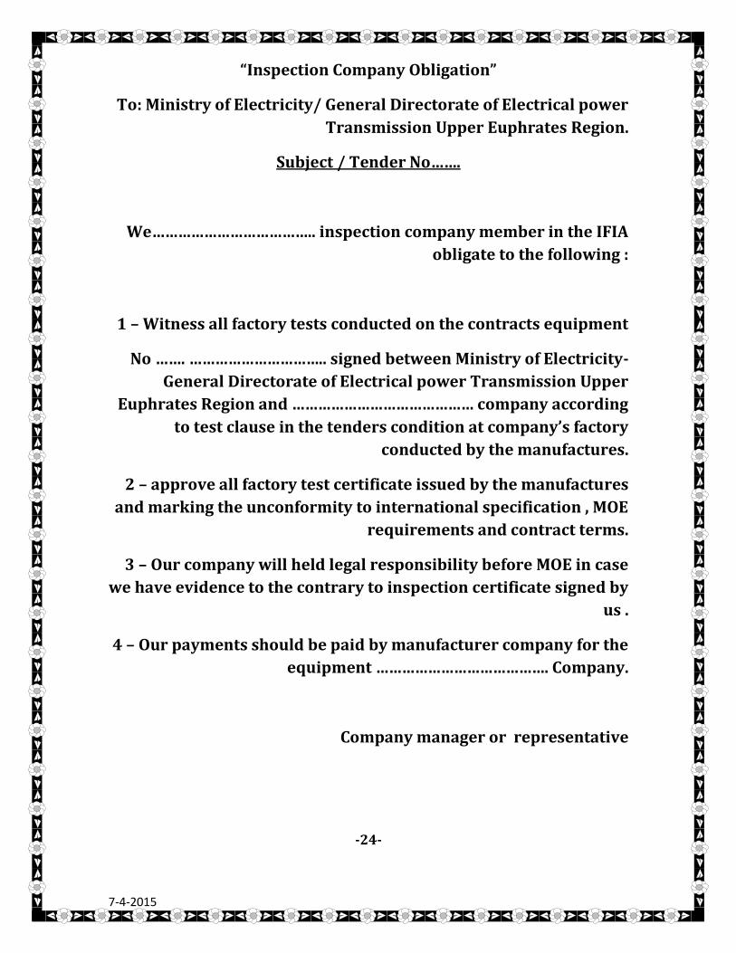
“Inspection Company Obligation”
To: Ministry of Electricity/ General Directorate of Electrical power
Transmission Upper Euphrates Region.
Subject / Tender No…….
We……………………………….. inspection company member in the IFIA
obligate to the following :
1 – Witness all factory tests conducted on the contracts equipment
No ……. ………………………….. signed between Ministry of Electricity-
General Directorate of Electrical power Transmission Upper
Euphrates Region and …………………………………… company according
to test clause in the tenders condition at company’s factory
conducted by the manufactures.
2 – approve all factory test certificate issued by the manufactures
and marking the unconformity to international specification , MOE
requirements and contract terms.
3 – Our company will held legal responsibility before MOE in case
we have evidence to the contrary to inspection certificate signed by
us .
4 – Our payments should be paid by manufacturer company for the
equipment …………………………………. Company.
Company manager or representative
-24-
7-4-2015
ATTACHED CD:
1. Tender
2.specification for 400/138.6/11KV mobile S.S
3. 400KV GIS presentation PDF
Note:
The tenderer should fill all schedules in volume 3 for the
equipment which will supplied in this tender.
-25-
7-4-2015