REPORT NUMBER FUSELAGE STRUCTURAL ANALYSIS · PDF fileStructural analysis on the fuselage...
97
REPORT NUMBER 144 FEBRUARY 1964 FUSELAGE STRUCTURAL ANALYSIS VOLUME III FRAMES, BULKHEADS AND FITTINGS ■ \..>l ■ \ ! » - ■ / ; rf i ; , V ■ ■ - ■■ I VI '■■■■ ■ I 11 IIFT FAN FLIGHT RESCARCH AIRCRAFT PROGRAM > / /1 - i. i 'r' /; !' tON^HftCI NuMRClf >.'/*< <"5 s GENERai ^tlECTBlC
Transcript of REPORT NUMBER FUSELAGE STRUCTURAL ANALYSIS · PDF fileStructural analysis on the fuselage...
REPORT NUMBER 144
FEBRUARY 1964
FUSELAGE STRUCTURAL ANALYSISVOLUME III
FRAMES, BULKHEADS ANDFITTINGS
■ \..>l ■\ ! »
- ■ / ; rf i ; , V ■ ■ -
■■ I VI '■■■■ ■I 11
IIFT FAN FLIGHT RESCARCH AIRCRAFT PROGRAM >/ /1 - i. i 'r' /; !'tON^HftCI NuMRClf >.'/*< <"5 s
GENERai ^tlECTBlC
**•■«;■
Report Number 144 February 1964
FUSELAGE STHUCTURAL ANALYSIS
Volume III
FRAMES, BULKHEADS & FITTINGS
XV-5A Lift Fan
Flight Research Aircraft Program
Advanced Engine and Technology Department
General Electric Company
Cincinnati, Ohio 45215
This document has been approv for publ'c release end sale; ha distribution la unlimHed.
rrTl D D QT
rV; SEP 1 5 1967
B

CONTENTS
Page
INTRODUCTION BULKHEAD F. S. 35 BULKHEAD F. S. 85 BULKHEAD F. S. 91 CANTED BULKHEAD F. S. 145. 3 BULKHEAD F. S. 165. 2 FRAME F. S. 177.2 FRAME F. S. 188. 9 FRAME F. S. 201.9 BULKHEAD F. S. 214 FRAME F. S. 287 FRAME F. S. 296. 5 BULKHEAD F.S. 316.5 BULKHEAD F. S. 341 FRAME F. S. 366 CANTED FRAME F. 8. 389. 7 VERTICAL STABILIZER FRONT SPAR FRAME VERTICAL STABILIZER CENTER SPAR BULKHEAD VERTICAL STABILIZER REAR UPAH FRAME PITCH FAN MOUNTS CANOPY SUPPORT LOADS SEAT SUPPORT STRUCTURE AFT MAIN FUEL TANK DORSAL FUEL TANK THRUST SPOILER UPPER LONGERON SPLICE FITTING F.S. 214 LOWER LONGERON SPLICE FITTING F. 8. 214 UPPER LONGERON SPUCE FITTING F.S, 287 M. L. G. SUPPORT FITTING F.S. 287 M. L. G. DRAG STRUT SUPPORT STRUCTURE M. L. G. MODE CHANGE ACTUATOR SUPPORT FITTING FLAP INBOARD HINGE FITTING JACK PAD FITTING THRUST SPOILER ACTUATOR SUPPORT TAILPIPE AFT SUPPORT PARACHUTE ATTACHMENT STRUCTURE
1 2 3 4 5 6 7 8 9
10 16 19 22 23 24 25 26 28 29 30 35 41 55 59 60 64 66 67 68 73 80 82 83 84 85 86
ill

■mmn
INTRODUCTION
J I «The structural analysis of the Model XV-5A fuselage frames, bulkheads,
fittings and miscellaneous components are presented In this report Model XV-5A la a U.S.Army V/STOL lift fan research aircraft.
The
A summary type load analysis is presented for each component, with the primary intent of showing the structural configuration, final critical loading and unusual assumptions made. Structural adequacy of many of the primary components has been demonstrated by proof tests.
Structural analysis on the fuselage forward and aft box structures is given in Volume I of this report, and the analyses for the fuselage center section and propulsion system mounts are presented in Volume II.

BULKHEAD FUSELAGE STATION 35
(Drawings 143F084 and 143F070)
The bulkhead at Fuselage Station 35 ties the two pitch (an support beams together and distributes shear from the nose fairing Into the box beams. The pitch fan thrust dlverter door forward pivot fitting is also mounted on this bulkhead.
Nose Fairing Side Shear = 464# Condition LO-3
Nose Fairing Vertical Shear - -1077# Condition F-5P
Load applied to forward pivot fitting by thrust dlverter door = 750# (Door @ 45° open position, load acting 20° Inboard from vertical).

A 7
r BULXHEAD FUSELAGE STATION 85
(Drawings 143F087 and 143F071)
The bulkhead at Fuselage Station 85 supports the pitch fan thrust dlverter door aft pivot fitting, and the pivot for a bellcrank which is part of the dlverter door actuating mechanism. Ultimate loads applied to the pivots, for two critical door positions, are shown below.
^ S^
A ' oo&rz pusor
B : ßeLLce**>< Pusor
CotJD. T — Doorz 4-S' ora^J
5A * go*-* 5 2.Z-7 ^
■ 3 /o *
COAJD . 1Z — PooJZ SI
VA = ft,? * S* = 4-Zi ? *
Vß » 5j -
32.ZO '

BULKHEAD FUSELAGE STATION 91
(Drawing 143F005)
Bulkhead Fuselage Static» 91 provides transition from the nose structure to the cockpit region structure. Loads from the pitch fan box beams are redistributed to the primary structure aft by bulkhead Fuselage Station 91. Also, the bulkhead redistributes loads from the forward ends of the wheel-well side beams to the fuselage primary structure. Other loads are applied by the windshield oenterllne frame, pitch fan aft mount truss, control system bracket and pitch fan diverter door mechanism brackets.
Loads for the critical conditiont redistribution of wheel-well loads, are shown below. Three-point spring-back condition Is critical.
2.0.A-
C3Ö '29j & Ztf)

I I I I I T
CANTED BULKHEAD FUSELAGE STATION 145. 3
(Drawing 143F006)
The canted bulkhead redistributes side shear and torque from open cockpit region to the closed box section aft. Shears from the aft ends of the wheel-well beams are distributed to the aft box section. The aft end of the cockpit is closed by the canted bulkhead, which also supports the seat mount rails. The upper portion of the bulkhead incorporates the canopy hinge support structure.
Loads for the critical condition; three-point spin-up condition, are shown below.
//J,
B

BULKHEAD FUSELAGE STATION 165. 2
(Drawing 143F078)
The web of bulkhead Fuselage Station 165.2 supports the forward end the main fuel cell. Vertloa.'. load« are applied to the bulkhead by the aft ends of brackets, which back up the upper portion of the North American seat mount beam«.
Critical loads are summarlzedt
Fuel Pressure! Crash landing condition.
Ult. Horlcoctel Load Factor = 8
Ult. p - (214 -£65.2) ^ x 8 - 11 pal
.3€SO S9$o*- (izep p. -^

FRAME FUSELAGE STATION 177.2
(Drawing 143F079)
The frame at Fuselage Station 177.2 functions as a stiffening member for the fuel cell liner. The loading consists of Internal pressure applied by the fuel. Two critical conditions are considered; horizontal crash landing and 6 g maneuver.
6.S-
PRAhJG CO/lX>ej} UJf&TM » /2 t^.
\/e&T/c*c d&AO » 4ö /^
Our. ^x - to* £ L.'S 31
^ * &si5 i>s;
OTi H-^^ - ^.75-^ /2, * ^/ ^//AJ.
V.
5^-
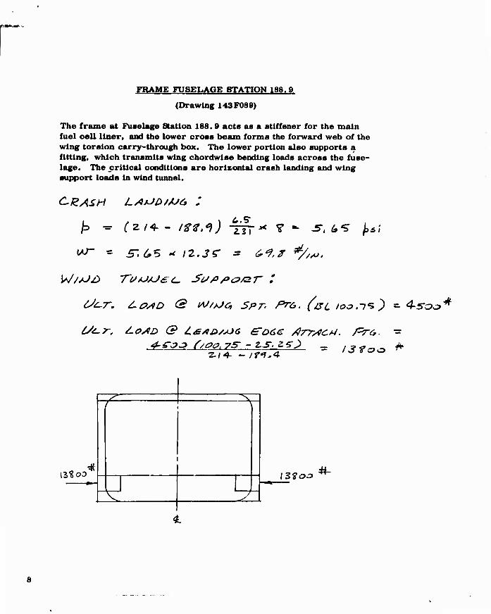
FRAME FUSELAGE STATION 188.9
(Drawing 143F089)
The frame at Fuselage Station 188.8 acts as a stlffener for the main fuel cell liner, and the lower cross beam forms the forward web of the wing torsion carry-through box. The lower portion also supports a fitting, which transmits wing chordwise bending loads across the fuse- lage. The critical conditions are horizontal crash landing and wing support loads in wind tunnel.
C12ASH L/i*JD/AJ6 :
2.z\ ? - -S". ^ /,*;
6St~T. JLO/ID & M/tJc SPT- Prt,. (ac /oo.ii) - 4-5-C?L?"*
TZZ ^
15? oo
^
IS^OO

FRAME FUSELAGE OTATION 201. 9
(Drawing 143F081)
Frame Fuselage Station 201. 9 atiffena the main ftiel cell liner. The frame is loaded by internal fuel pressure. Two critical conditions are considered; horizontal crash landing and 6 g maneuver.

FUSELAGE BULKHEAD - STATION 214. 00
The bulkhead at Fuselage Station 214.00 oonslats of the fuselage aectlon of the wing forward spar together with a full web framed and stiffened by formed aluminum sections. The bulkhead serves to redistribute ftiselage torsion and fuselage and front spar shears between the space frame and the forward ftiselage structure; to support the forward engine support frame ( Reference Volume II, Section XIII) and aa the aft pressure bulkhead to the forward main fuel tank.
A sketch of the bulkhead with applied loads and reactions for two fuse- lage loading conditions is shown. The loads applied to the bulkhead are determined as follows:
1. Space frame forward reactions. These loads are taken from Section DC of VoiVme II for the desired condition, and are applied at the longeron-bulkhead intersections. Loads include kick loads developed by axial loading of the angled for- ward longerons..
2. Wing forward spar loads. These loads are derived from the dif- ference In fuselage shears and bending moments between Station 214.00 forward and Station 214.00 aft in "Structural Design Loads", Report Number 143. The loads have been transposed from the fuselage reference axis to W. L. 100.00 for clarity of presen- tation.
3. Forward engine support loads. These loads are taken from Section VI and distributed to the bulkhead per Section XIII of Volume II.
Reaction shear flows are provided by the forward fuselage torque box bounded by the longerons, and are calculated assuming uniform shear flow to react torque and side load, and vertical load reacted by hori- zontal and vertical webs respectively.
10

FUSELAGE BULKHEAD - STATION 214.00
Loading Condition L-10 Rev.
Ultimate Loads
IAJ.L.IM.O» J&C*
ssnr
V* t. ITM
a *
N i*ojam r»>p Mpery. '//c Sr*tf
XX

UI.4..IM.«»
FUSELAGE BULKHEAD - STATION 214. 00
Loading Condition Roll 4P Rev.
Ultimate Loads
tV.i.fMkOO
tt.L. 1f.fi
14C*
f- IK*/*
^ ^at/^<f run JAfiee*. '//c JLA,,*-
12

FUSELAGE BULKHEAD - STATION 214. 00
Bulkhead Pressure Loading;
Maximum fuel pressure is exerted on the bulkhead during landing con- dition L-16, dynamic spring-back condition.
flx = -2.73 Ult.
nz = 5. 67 Ult,
p = .0281 psi/in./g
p = .0281 (49.00) (2. 73) « 3. 76 psi uniform pressure 'x
p = .0281 (25.77) (5. 67) = 4. 11 psi @ spar upper cap - W. L. 106.23 z
Total maximum fuel pressure on the bulkhead web varies linearly from 3. 76 pel at W. L. 132. 00 to 7. 87 psi at W. L. 106. 23.
13

FUSELAGE BULKHEAD - STATION 214. 00
Front Spar Attachment Fitting
Ref. Drawing No. 143F010
^ro)!;!':©
iß/i rrsn
«-..ta.» (jr*tlt-~
14

FUSELAGE BULKHEAD - STATION 214. 00
Front Soar Attachment Fitting
föpe*'7 A-i ■ hsH&^f, f>. /&4J
Ffy . f9, Lev **
ft ■- /3>/SVP **
7?A JU*> Jus- e>s=- .s<,>r,,siirr»y s* Jecse*/ Ae<;*>f*s fZ-e -n # //rf/K/v* rtft >=!?*> >•«'<■>' /*.Ai.& . TTjerf £***. /Ir/iii. S**J£>
/AJCr] JuAsf /fZB j ^. /i,o.
LU/c. . *-">//■ iZi* ~ 3.if ft. yg {ku^e4J (X/O = 2oo/t./t4*' /.Tß fifaz /.ty
A* -, (ilo- I-1t*S){/.g4*J. 3.ZOO >AJ » Aur ' 't.4S ^/ zis)^ /.too ,*J*
A,: At * A5«-^/t/«). /.fetf/ /«J«-
Al' A3 = l-Ztftf/ 24*)* /.Lot /*/•-
^/V= 'u/i-4*c' ''I z^- ix* Cr* 'fj
f?^ «If^l- -700 (.7^)^ a m.
**' m?^>- ■<"*- Co'*)"
*** Tkr^^-^
15

FRAME FUSELAGE STATION 287
(Drawing 143F019)
The frame at Fuselage Station 287 redistributes loads from the center section truss structure to the aft seml-monocoque structure. Secondary loads are applied to the frame by tailpipe and aft fuel cell support fittings. M. L. Q. loads are applied to the frame through 143F020 attachment fittings, which also functions as an integral part of the frame.
A
50Z.5
C^O/JD. 1.-/G--
■ST^'Z-O
J<933 O 30030"
18. ST
12.(2,0 ^//w-
502.S M
154-/ *"// itJ.
W. L.<lS.tü
16

FRAME FUSELAGE STATION 287
Critical symmetrical condition is L-16 tail-down, spring-back landing.
Loads applied to the M. L. G. attachment fitting by the landing gear and space truss are computed on Page 68 .
Total vertical load/side = 31950 + 18800 - 2 x 6415
~ 37920* (appUed @ B. L. 18. 57)
Total side load/side - 28000 + 1280 + 1570 -820
= 30030# (applied @ W. L. 95.86)
Loads applied by upper longeron cluster are given in Volume II, Soctionxi The longeron is normal to the plane of the frame, and therefore does not apply any in-plane loads. The X brace applies a side load.
Ultimate load (member 9-13) = 1. 5 x 3432 = + 5148#
Side component = 5148 x . 5883 = 3025#
Distance between longerons = 36
37920 Reacting shear flow = —-~— = 1052 #/in.
36
Curved panel above upper longeron is leaded by shear flow resulting from unloading upper external longeron and effective tensile skins. Total load is determined from bending stresses at Fuselage Station 296. 6 given on Page 115 of Volume I.
17

FRAME FUSELAGE STATION 287
Xrri ** t * * /, /=>•■ S*^
Lo*iC. ,13.4- .of fos-rz. 4e>t 1 /r .031. .O+f .a 447ri /f/
Z f.i-2. ./447 .ol WCOi- & + & 3 C.OI .MLt- .// 4t?sz /t?S Z. 4- s;4(. .1*1/ ,13 4£4oa //fo f r.ll JO/f ,11 4tu<f /J7 7 C t.*4- .rtSt .23 JS-7II /s-ff 7 L.OZ. .mf ,-& •Zfo7S Z.// o f 4. -r • o JT. ./*<f- / Zeit* 2.*>4*
1/94-0
TOT/M. _Wtf-/f« /*/£>* - 2* f^* .* z,c * l7Coo *
18

FRAME FUSELAGE STATION 296. S
(Drawings 143F021 and 143F022)
The frame at Fuselage Station 296. S distributes the wing rear spar shears and unsymmetrlcal B. M. (fuselage torsion) to the fuselage box. Wing symmetrical bending moments are carried through the fuselage by the frame lower member, which Is a continuation of the wing rear spar. Loads for the critical symmetrical flight condition are shown below (Ref. Wing Stress Analysis. Report No. 130 Page 134 ).
^- So.U *-/,*,
t fz » 174:2. */,*>
IIGtn • **-
19

FRAME FUSELAGE STATION 296. S
Rear SPar AtfauAmant Fitting <14aF022>
HAj>e FIZOH :
F0R.Ce-J> DICLCT
CSo&o (.ST)
£ » tlc I
^ "■ fJ£/ cos /T f /Ofooa J/AJ /7" « 37foo ^
20

FRAME FUSELAGE STATION 296. 5
Rear Spar Attachment Fitting (143F022)
Lug 1B analyzed by Melcon-Hobllt method from Product Engineering. June 1863, Page 160.
W/l> = 4-/fi(z5 * ?is^ /<t • ,77 faat/r 4)
*-/£> » z//./Z<r » / 7/
Ar - (4-/./ZS)/.ZS -/.«f* ^ ' /./ZS-^/.ZT^/.^-oP
A, - A+ ■* t.sf */.zs ■*■ l.tTS
'^/ik' m '(7472 */.?-><, ^ /,0 7* ' * '■'"
/3L03 o . 74-5 C**-*) ' . fet«»-
/2tir. - ?7T>=»J. » .Mf 62.i*')'t - ■ ^±±
21
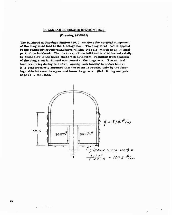
BULKHEAD FUSELAGE STATION 316. 5
(Drawing 143F025)
The bulkhead at Fuselage Station 316. 5 transfers the vertical component of the drag strut load to the fuselage box. The drag strut load Is applied to the bulkhead-through-attachment-flttlng 143F118, which is an integral part of the bulkhead. The lower cap of the bulkhead Is also loaded axially by shear flow in the lower shear web (143F0S7), resulting from transfer of the drag strut horizontal component to the longerons. The critical load occurring during tail down, spring-back landing is shown below. It is conservatively assumed that the shear is reacted only by the fuse- lage skin between the upper and lower longerons. (Ref. fitting analysis, page75 , for loads.)
SS.S
^ qvtft^*/^
Ü
22
**
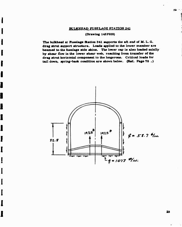
BULKHEAD FUSELAGE STATION 341
(Drawing 143F029)
The bulkhead at Fuselage Station 341 aupporta the aft end ot M. L. O. drag strut support struoture. Loade spiled to the lower member are beamed to the ftiaelage aide aklns. Tbe lower cap la alao loaded axlally by shear flow in the lower ahear web. resulting from transfer of the drag strut horizontal component to the longerons. Critical loads for tail down, spring-back condition are shown below. (Ref. Page 76 .)
f $»■ s-r.7 H».
077 *Y/*J.
23

FRAME FUSELAGE STATION 366
(Drawing 143F0S3)
The frame at Fuselage Station 366 redistributes side shear and torque from the full fuselage section aft to the forward section, where the lower skin is replaced with the lower shear web to provide space for the M. L. O. Net frame loading is found by subtracting shear flows on the forward section from those aft. The critical condition is LO-4 Volume i.
Pages 147 and 160).
4-. 1 #//^,
24

«c.-**
CANTED FRAME FUSELAGE STATION 389. 7
(Drawing 143F038)
The lower fuselage akin aft of the canted frame Is eliminated by the tail- pipe exit nozzle, and la replaced functionally by a shear web above the tailpipes. The canted frame at Fuselage Station 389.7 redistributes lateral shear and torque between the fore and aft sections. Jacking and hoisting loads are also distributed to the fuselage by this frame. Re- distribution shear flows for the critical condition, L.G-4, are shown below. Critical load applied by Jacking fitting results from supporting the airplane in the wind tunnel (4500# down and 1500# aft).
4£.S%A
'^•3^//^
SOSO* (W/UD TU/J/JeC SPT. LOAD ) EBAC. T/OAJS /JOT ^Ot*SAJ J &£.*=. P. ¥3
26

VERTICAL STABILIZER ATTACHMENT
The vertical stabilizer la attached to the fuselage by means of three
frames which are Integral portions of the three spars. The Mc
dis-
tribution of bending moment to the three spars at the root station is altered to allow for possible inaoouraoies resulting from the sweep effect. A conservative overlap distribution is assumed. Spar bending moments are computed below from bending stresses computed in Ryan Report No. 132 " EMPENNAGE STRESS ANALYSIS
Page 101. Condition LG-4 is critical. Total shear is distributed in proportion to the spar bending moments.
B. M. % Total
Front Spar - 13.1x .175 x 23530 = 53800 22.5
Center Spar - - 14 X; 462x25147 = 162800 68.1
Hear Spar - 7.6X .216 x 13651 = 22400 9.4 239000
Assume Following Distribution:
B.M.* Shear*
Front Spar 25% 66000"# 1325#
Center Spar 75% 188000 3975*
Rear Spar 20% 52800 1060#
♦Root B. M. = 264000,,# Root Shear = 5300#
Spar Axial Loads
Maximum horizontal stabilizer shear of -10653# (Ref. "Empennage Stress Analysis", Report No. 132, Page 6) is distributed to spars as follows, (critical condition is F-12):
Front Spar 1300#
Center Spar -6360#
Rear Spar -5000#
26

.Of?*
I I I I
VERTICAL STABILIZER FRONT SPAR FRAME
(Drawing 143T005)
Frame distributes vertical stabilizer loads to fuselage. Two critical loading conditions are shown below.
&£&<>=> _ 4.4^ 0 #■
OOAJD. 1.6-4-
14.1*-/."
27
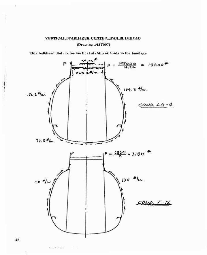
VERTICAL STABILIZER CENTER SPAR BULKHEAD
(Drawing 143T007)
This bulkhead distributee vertical stabilizer loads to the fuselage.
75
If4-.3 */»«
3^ -»«s T^
I 22.5." ►•'*/'*'• A ■
13 g HfJ
p * Wz£.*3l8o *
\IS H~.
£OAJ£>. FjjZ
28

^jypnW1"^1
VERTICAL STABILIZER REAR SPAR FRAME
(Drawing 143 TOO 9)
The rear spar frame distributes vertical stabilizer loads to the fuselage.
P
lOl *{,»
lb* tfl l*)
p p ' • r
fi f \
f \\ / :
' i 1
r4
VJ 1 1 1 J
sooa - Z,S"00
^ I'** V/Ai

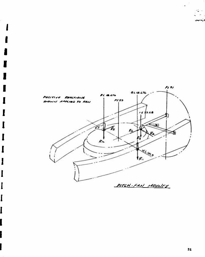
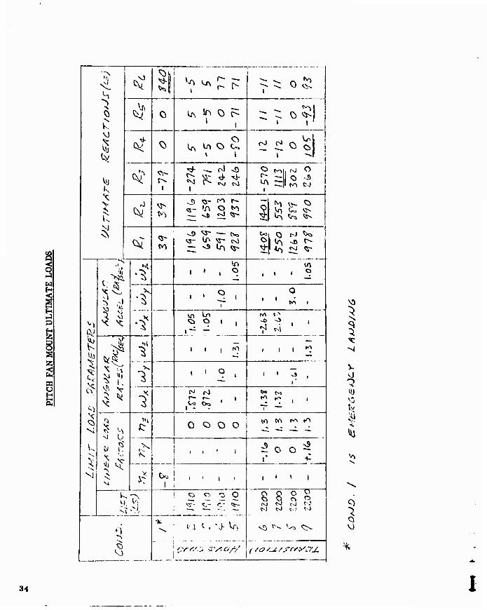
PITCH FAN MOUNTS
The pitch fan la mounted at 3 points: two at the noae aide beams and one at the aft tripod which Is supported by bulkhead Fuselage Station 91. The left hand side mount reacts only the vertical load am* the right aide reacts both vertical and longitudinal loads. Loads In all three direc- tions are reacted at the aft mount.
Reacting loads for unit values of applied lift, linear and rotational inertia, and angular velocity are given In the load report. Net reac- tions are obtained by multiplying unit load values by inertia and velocity factors specified in the design criteria. Report No. 122, and combining these loads to obtain critical conditions.
30
PS II
fSS9
s>/r£*-/?/*AJ efgitoMs-
31

PITCH FAN MOUNT LOADS
Baalc Data (Ref. O.E. X376 Pitch Fan Specification #113. March 1. 1982)
Weight and C. G.
W - 10 @ Fuselage Station 61. 27. B. L. 0 and W. L. 100. IS
Moments of Inertia
1^ = 2.646 Slugs-FT2
I = 2.530 Slugs -FT2
I = 5. 175 Slugs -FT2 z
J = 1.293 Slugs-FT2 (Polar)
Fan Sbeed
4684 RPM (Maximum short-time overspeed limit)
4481 RPM (Maximum continuous speed limit)
Fan Lift
T = 1910# (MIL. Power, S. L.. 30 kts) (hovering)
T = 2200# (MIL. Power, S. L.. 125 kts) (transition)
Critical Conditions
(Ref. Report No. 122, "STRUCTUIIAL DESIGN CRITEniA" for condition defining parameters.)
Emergency Landing
»7X = -8.0 Ult.
32

PITCH FAN MOUNT LOADS
A^AJ t/Ar * /f/o* /*7Ä = o -ro /, 5
t*Jx « S . f?z £*■>/*&£. tJx ^ t /.as- e>t£/jr£c *■
P*AJ l/s=r - 2ZOO* f7y ■*■ t-./t r?^ *■/. 3 r-o z.o
i*Jy « t /.32 JPAM/Jfc c*Jx * t Z.(.2 £*&/set'-
uJ y * ~ . 6/Ö eAO/j£C. t*Jy = +3. OO &JO /jBC ^
UJ?. ■= t /.3/ ZA^/JSC ÜJ* a £ /.OS gyic/s&e.^
<:o**/r/*j£-£> M/n* t-s^r s4*yj> ^.//Utrstje /q£.eLer<.<Fje/t -
33
d
w
S
^ i ^
^v ^^f:^ i - o^
^ 1
^ 1
^ 0 iJN 1^ 0 C^ 1 I
-
ß? Ci U Vn O ^ rJ
^ rf ^_ rl «0 o
i
r-» O -.5
11-^ c-J !
^ ^
^ <5- c"» r-
•m*. «SÄ ^ ^* 1 ^ ^ ^ Vr) U. «J^ ^ ^> ^
<V Q- fn
o ^s- — CK. VS- ^ VS~ rsl — NS Lr\ Q-
^ vs r- i Ir, _«vj V
1 ' ° k ...
• ' 1 ^ 1
1
O 1 11 t« i
vn ^ Ci O 1 (
r4
1
l l 1 rrt i i i «O
' ' ? . i {
i "1
o o o o «A M r^ t^
y 1
i i ' i J 0 O^?
+-
' > 1 j I'II 1
] c.) o o O ! <s~ t,- cr «s-
8 S S" i <s) r-J tJ rJ t-j <:N)
0 1
Ji/
v^ -^
^5
i?r^^ S'yio/-/ frsyc/j.
o
VN
34

CANOPY SUPPORT LOADS
Canopy pressures are obtained from Report No. 123, Page 45.
Pad loads 6 through 19 are assumed to be applied symmetrically.
35

CANOPY SUPPORT LOADS
ULTIMATE LOADS
PAO LM» u D M w»fc AK A« AM, a/Vv
C 7sro' jr&z /4S - /43' 13»' J6.( 4-.1. iojoa 610 7 too Si.* o /SO - 1^.1 *52SO t 5SO 4ti~' Q 15^ - IO.I ' fno ? 4oo JOO a 15^0 - 1.1' 1T3Ö IO 740' 740 l*H ' ai 14-/ 31.» M> i«ZOO no // 74o 74* £4. Jt^ t<Vl. 3o.( . Z. 112 59 1 0 /2 sva •rv»o o »37 • n.« IU50 /J 3O0 I»J o \** - H.I ' 33V3 1+ 2,10 Ho O 1*1.'
« ?./ 7lo
is n* l** 17* Ill I4| 3// I.u jo«oa Zio /i. 7*0 750 • 65-- »17 14^ JV.I . 1 14-OTO 10 /7 tro 4«ra i> 121,' - H.l lojyo /* 3SO 3SO o 14* - K.i f^iO 'f Z30 VZö O ist - ^-.1 ISO
Z tr?*) -5-9 J «is-oo lote
XH. <?• ^M«. /1Ä-6- TOTAL HoH**Jr AOJUr PI^OT
Pi. V * Pt c** 31.S' •• .T^-J Pt
6>t.T /s/Dff
36

CANOPY SUPPORT LOADS
TOTAL PIVOT LOASS I
<Z/ZA6H LAKHilhJG COAJD.
ULT, LOAO PACTP/Z * 4o
37

CANOPY SUPPORT LOADS
Distribution to Hinge Fittings
^5 bO
33?o^
Z5.5
CAtoTes "BLKHD
^£Ar FAfL £
Assume Following Distribution (Conservative Overlap)
. 50 Center . 376 Ends
V = 6560 cos 25. 5° + 3380 sin a/>. 5° = 7380#
D = 6560 sin 25. 5° -3380 cos 25. 5° = 530#
Center Ends
Vc = 7380 x .5 = 3690#
Dc = 530 x . 5 = 265#
VE = 7380 « . 375 = 2770#
DE = 53« x . 375 = J»00 #
38

CANOPY SUPPORT LOADS
Latch Loads
4-260 T^ UCT, Lo/Iö (PL PKoM&i. /2><*>)
FS /^^><f^
*^ ¥o o ^
IISO
rMj = o
4260 x 4. 28 = 5. 7 PB
PB = 3210#
Loads applied to -63 @ points 1 and 2 by graphics shown above as applied to -63 channel.
FS 12s.£
39

CANOPY SUPPORT LOADS
Latch Support
Frame Loads
FS ll'L.S
>'
55
V, ll^o
3o3o *
^.Z-L
T ts
i.
^S '31.S~
,*
7<x> * '
isoo*
—«rV D
/.
D = -3000 + 800 = -2200# (Reacted aft only)
11. 01 Vj = 1150 x 10. 06 + 3000 x 2. 5 + 2500 x . 8
Vj = 1920#
V2 = 2500 + 1150 -1820 = 1730#
40

SEAT SUPPORT STRUCTURE
(Drawing 143F006)
The pilot and passenger seats are supported by rails attached to the canted bulkhead at Fuselage Station 145.3. There are provisions for mounting two different types of ejection seats. The structure was first designed to support the North American Aviation, Inc. lightweight seat, and then modified to also accommodate the Douglas Aircraft Co., Escapac I-C seat. Since the seats are interchangeable, loads for both arrangements are given.
Seat ejection and crash landing are the critical conditions.
The NAA Bfiat is attached to the support rail at four fittings. Since the attachment reactions are redundant, a simplifying assumption is used that only two of the supports are active. Loads are then computed for all combinations of two reactions.
The Douglas escape seat is supported by two tracks through a set of three rollers. It is assumed that the normal reactions on the lower pair of rollers are equal.
41

SEAT SUPPORT STRUCTURE
(NAA Seat)
3o%
n* * ± JO
MT. » 33/.7 *
42
^*t3»-
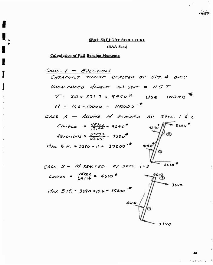
SEAT SUPPORT STRUCTURE
(NAA Seat)
Calculation of Rail Bending Momenta
COAJZ» . / tETJac T/O/U
7~= Jo < J3/.7 = T^^o ^- (jse. I&OOQ ■4
CASE /? — /)ssi//-f<s /S /2&*<z,r<sui /sv SFTS. / f
Coupes » pg^^qp * ^«2^-0 ^^o
34-. 0 4-
/-/AX: S,M. «- 33?o--// « 37ZOO
^T/lSfi Z? - M eeAcreo B/ SPTS. /-J
3.5?o
1?.<Vq
3 5 3o
/Y/>x KA</ * 35?o *I0.(*~ 3S2oo n*
4-Cto
35 ?o
339a
43
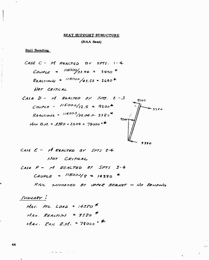
SEAT SUPPORT STRUCTURE
(NAA Seat)
Rail Bending
C4S£ C - M KB Acre o rs y sprs. 1-4-
JJcr CX/T/CAC
(ZsACTIONS, =• //^::>:33/34.C>4-.=- 3i7o^
hiA< ß.rf. » jfjyo < Zio* x 79000 «^
fioo
lloo-i
%Z3o
3 190
CAie £" - /4 JeeAcTfi» at' SPTS 2-4-
tJor Cte/r/cAc
CASH F - rf jZGAOTeo sr Sprs 3- 4
tJA*- fira. L0AJ> • /f-JFo
t^A* je£Acn3*J * S3?o #
/^^v. ^»^ x^A/. - 7?ooo
44

SEAT SUPPORT STRUCTURE
(NAA Seat)
Loads and Rail B. M. for Crash Landing
izloo
I zwo
IfiO ISZSO Co; /3' =. I?.4oo*-
(2-V4. (2.4-4- * '^tOO
^S-Jo'
3-5T O
■LOO:.
1. 5 » 6^00
(^oa-M -iooo -<i3.<J-* -ia.0«*-^ i^OJ
??, |5io
46
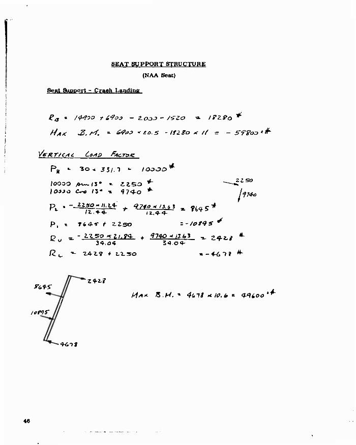
SEAT SUPPORT STRUCTURE
(NAA Seat)
Seat Support - Crash Landing
MA* -Z.rf. ~ ^"J 'to.S - ItZgo * // = - S??oo*^
P» •- "So ^ J5/.1 - loooo*
I03JO <%-o /3- » '97«^o *"
ZISO
p, s T6*T ^ ^^so zfotqs*
u 34.04 34.04- *.
^^^Z4-t9f 2.0.50 a-4-6T? ^
ions'
tUiit
46

I SEAT SUPPORT STRUCTURE
(NAA Seat)
y/£>€ 6.0*0 •*■ /S* 321.7 ^ 4'*l(*&'*
0 z- ? 3
rozcpce /rrc ~ C77*a/3 ^ Z2.(~Oo"*
47

SEAT SUPPORT STRUCTURE
(NAA Seat)
Upper Support Bracket Loads
Horizontal Crash Landing Condition
Z3~ ^oo*^±
J2 , •» loo o * ~)
into /?!. »■ 7400
R4. •- If?00 *
(^ T ^ T 6 2.0 "*•
S-f3o*
S ^tio4*
1T I i l (
i—Jil__ ,.!,..
F.i.ni.i.
Zu-lz
(.1\o*
\ZAoo
U~4%
izaoo *-
F.i. Ifo.yl
48

DOUGLAS I-C SEAT SUPPORT
49
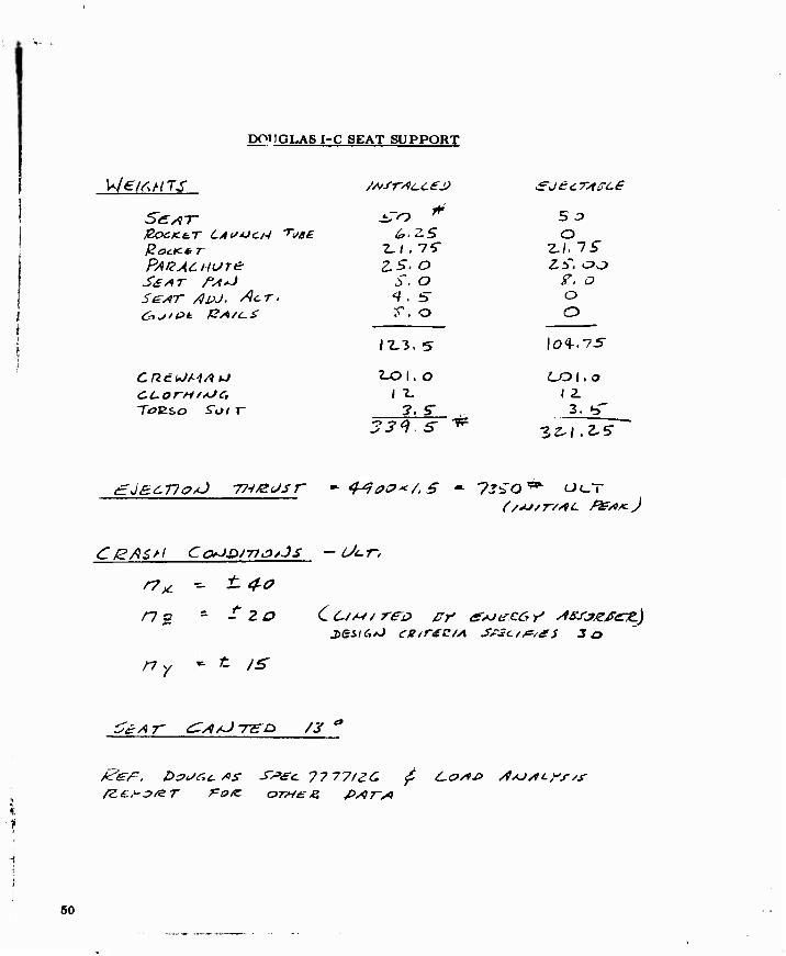
DOnOLAS I-C SEAT SUPPORT
Vle^nrs /A/sr/tt-cej)
S£yqT ^TO * P0CKe.T LAUNCH TiSBe 6>.ZS £oe.K*T 2./,75" pAQACHore ^5■. o SSAT r^sJ s. o Se/iT /)vJ. ACT. i. s- Oiji&k f2/*/c.£ r, o
12-3, 5
Cne.iJMA^ e-oi. o <^UorH'*JC, ( T-
TöESO Sot r 7. S-
So o
2./. 75"
7. o o O
I 2. 3, ^r
^J"?.5- ^ 3^/.2-5-
C/dJ/7-//VC f£/9Kj
50

DOUGLAS I-C SEAT SUPPORT
^ 2..C*. -5 ' 2J^ ^
51
DOUGLAS I-C SEAT SUPPORT
2,1. £.^
'-■' .f
rr
£<- -K^ -^ 73SO */7.
7
■Ei '- -yjßo ¥r
Z&Z'JJ &
f^/Jlj 4 /_g & JT/jier £SZ*S£L
COUP<L£ = S'O^O ^ /3.cC* - £?6?J " *
C~(P,JJJ . y: a ■>- 7 /c xc. £ a/s/w x? ££> S .-> c .-? / JJj 9 /
52

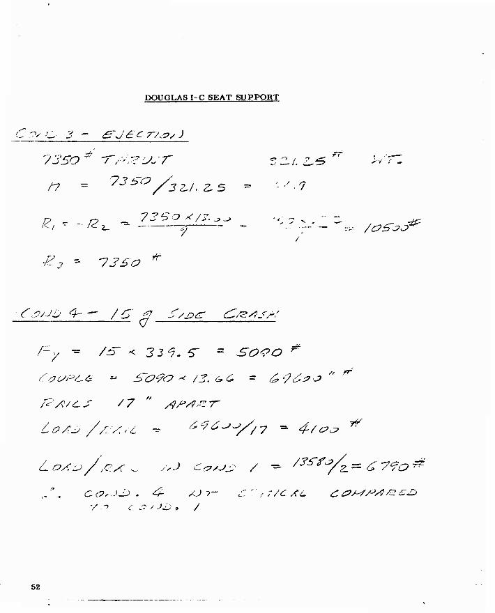
DOUGLAS I-C SEAT SUPPORT
TZo = ^ {4-7.SO * 3Z.S f ZZU7 x7+ /b-ZS </.1)
£c - /77Z. *
S/:'.o c vs 2/ 's<, ' * 4-7^ o j/ze? S/*J z/ 'St, ' -- W/o*
/77Z cos IT^' * /69o'*' /77Z ry^j/7'S-c' ^ SV-S *
53
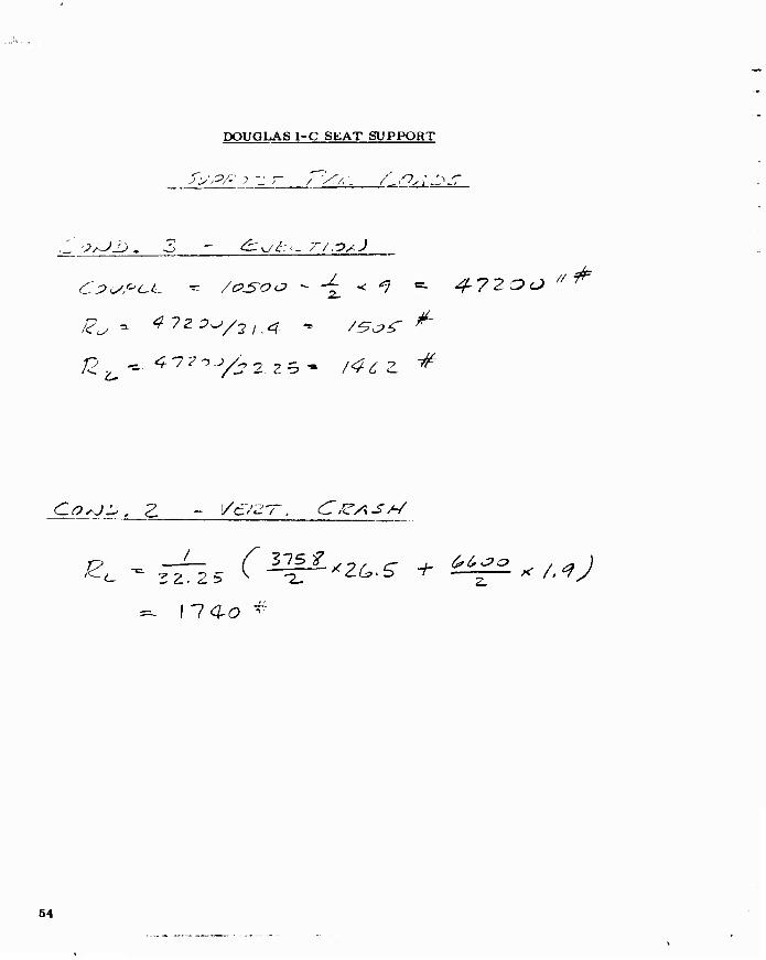
DOUGLAS I-C SEAT SUPPORT
Cl^CL. rr. /0JS-OO ~ ^ < *} *=- ^h7ZOO ^ ^
~ \14-o *
54

I I I I I I
AFT MAIN FUEL TANK
The aft main fuel tank ia a separate structure supported by the fuselage as shown by the following sketch:
Fszai
ML HZ.
VJL IOC
/f/ j? &z ' T&AJSSO*-) S-T^^Z» Ajar- /4 7-rsiCA'&& ra rwu*:
66

AFT MAIN FUEL TANK I l
Four critical conditions are considered: maximum A longitudinal load j factor and maximum * vertical load factor. Reacting loads are shown ,- for these conditions on the following pages.
£j j /£& j S^y f /^- S1/Z<S SIC. 7-/ V£
56

J AFT MAIN FUEL TANK
COAJD 3 — Z>0i*yjiJ £ 0/1L>
CZO*
67 I

1 AFT MAIN FUEL TANK
/2a
8o\
COAJ£> £> - A/^r £.£>*£>
/6£0*
58
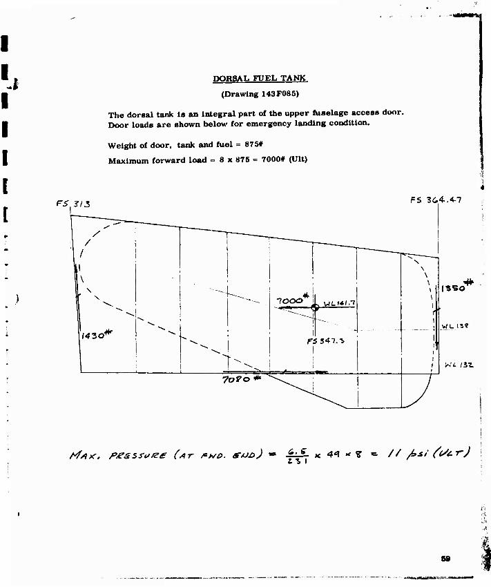
DORSAL FUEL TANK
(Drawing 143F08S)
The dorsal tank Is an Integral part of the upper fuselage access door. Door loads are shown below for emergency landing condition.
Weight of door, tank and fuel = 875#
Maximum forward load = 8 x 875 = 7000# (Ult)
1
15 FS 3G.4..4-7
^"" ___^__^ \
/ / _____^
i
/ N
\ \ "--^^
:
4t 1.
\
1 1
ISBO*" X
^ ""~^ 7000 i L UL14-I.T 1
^ ^ ~ ^ T ■^k , - -- |
{AZO* ^-^
^. <
i
!
i
1 1
1 1 ( i
WL IS?
7oVo * " ""^^^^ V
Z. % I // fisi ft/cr)
1 8»

THRVßT gmMSR (Drawing 143P069)
The thrust spoilers consist of a pair of doors located aft of the tailpipe nozzles and supported by the fairing structure below the fuselage box structure. The tailpipe exhaust impinges on the doors when they are extended. The doors are operated by a single hydraulic actuator lo- cated on the airplane centerllne. The actuator drives a rod which is connected to the door links. Longitudinal movement of rod and door links joint causes the doors to pivot about the door hinges located at the forward end. The rod/door links joint motion is guided by a track. An Idler link at the actuator/rod joint reacts vertical loads so that the guide track is not loaded.
The spoilers are designed for operation under the following condition:
100 kts.. hot day. 2600 ft., 9200# O. W. full flaps, 98. 6% RPM
Ultimate load per spoiler = 1553#
Load Is normal to the deflected plane and c. p. is at the center of area.
Unsymmetrlcal loading due to differential engine RPM of * 0. 6% is ± 40#
Design temperature = 1200° F.
60
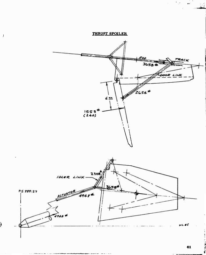
THRUST SPOILER
ISS3 Ct 4.0)
WLOS
61
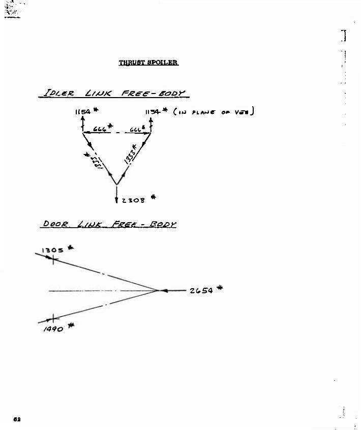
THRUST SPOILER
]
IPtLee. //x//C P&e-e- *ooy
1(54
t ^
Ä4t* <tt(. 4 ^ v
x # Ä
^\ v/
k. O«
^og/g Z/>ü>><r /g/e^g^ > ßo&y
ZCS4 *
/^^o
«a
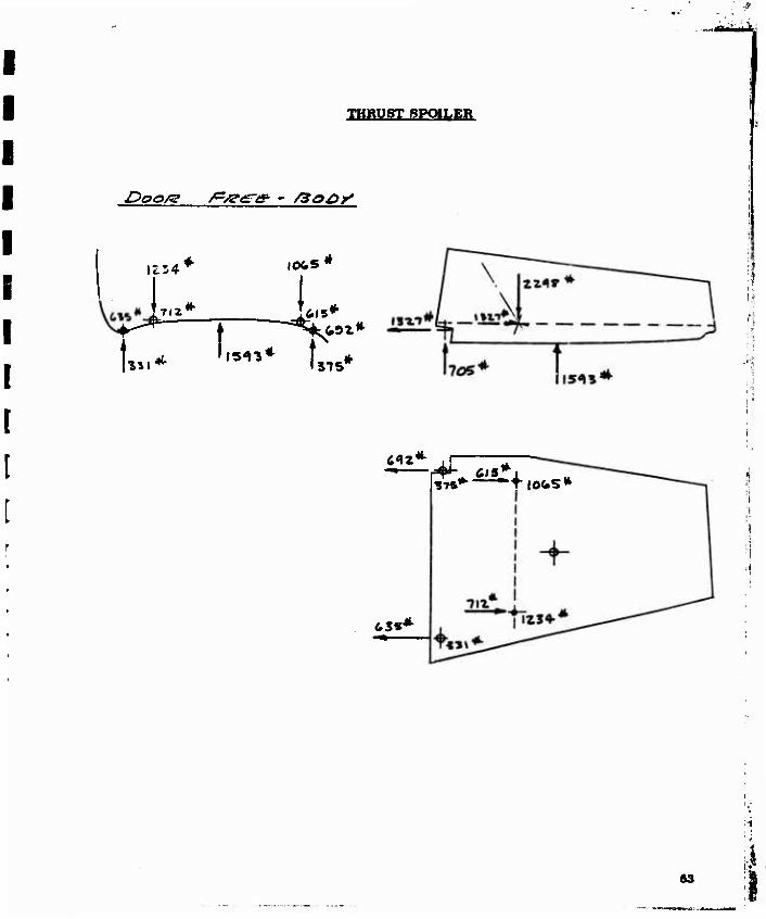
THRUST SPOILER
£>ooA2 /gggg* - /3o£>y
ni4*
l7,Z*
1065
Ls*
U.^ I,w* Ls*
m* if r
i
•STS*-"-"*^!©«.«*
63

UPPER LONQEROW 8MJCE F1TTIWO FUBELAQE STATION 214
(Drawlnta 14aF121 and 14SF122)
The upper longeron at Ftieelage Station 214 la apUued to the apaoe frame longeron pad by two bathtub type flttlnga. The longeron load la determined In Volume n. The maximum load oooura In lateral guat condition LG-3.
Ultimate load - 191B7# (Ref. Volume IT, Section XI)
Additional aide and vertlual ioada In the plane of the bulkhead are re- acted by Fuaelage Station 214 bulkhead. The dlatrlbutlon of load to the four tenaion holte la baaed on the following aaaumptlona:
1. The load la equally dlatrlbuted to the upper and lower fittlnga,
2. The dlatrlbutlon to the inbcerd and outboard holte la midway be- tween Ra equal dlatrlbutlon. and one which beama the loada from the longeron oenterllne (no lateral bending of longitude).
Load per fitting - 19197/2 - 9599*
Outboard Bolt Inboard Bolt
Equal distribution 4800# 4800*
Beamed diatrlbutioa 8610 1089
2 1 13310 2| 6889
Aaaumed dlatrlbutlon 6656* 2946*
64

Mf<-fl% "•"''^ ■
LI
VI
i 8
66

\ -^-
)
"\
-4- L-L ■
-^■
».
t— r ^-
I
% NJ
I
0/
^ M
I I
In
M ^
^
I
i NJ
66

UPPER LONGERON SPLICE FITTING'FUSELAGE STATION 287
Critical Load = 39000# (Ref. Report No. 63B131, Section XI)
L-16 is critical condition
4 7 5-0^ -*
<tlso* ^
67

68

MAIN LANDING GEAR SUPPORT FITTING STATION 287
(Drawing 143F020)
The main landing gear vee-brace/main strut pivot Joint is attached to the fuselage by the fitting at Station 287. This fitting also splices the space truss lower cluster to the aft lower longeron and bulkhead at Fuselage Station 287. Loads applied by the main landing gear are ob- tained from H.W. Loud Machine Works, Inc., final stress analysis report for the main landing gear. The loads applied by the space truss members are obtained from Volume II, , Section XI. Ver- tical loads are reacted by bulkhead 287 side member and the unbalanced moment is reacted by a couple in the z-y plane. Longitudinal loads are reacted by the aft longeron and two stiffeners on the lower shear web. The distribution to these three members is based on estimates of the relative stiffnesses determined in the preliminary analysis. Unbalanced moment in the x-y plane is reacted by a couple in bulkhead 287 and 296. S lower flanges. The unbalanced moment in the x-z plane is reacted by kick loads, Kj and K2. An overlap assumption of 7t>% of My taken each by Kx and K2 is used.
Tail-down, spring-back landing (landing condition 6 or fuselage loading condition L-16) is the critical condition.
* Loads Applied to Pivot Lugs
Lateral load = 1.5 (-18677) = -28000« (acting Inboard)
Loud Machine Works loads are In the vee-brace/main strut plane, which is 10.5° from vertical.
♦Ref. Loud Machine Works Report No. 15I0L00. Page 166.
69

MAIN LANDINQ QEAR SUPPORT WTTINQ^TATIOW 287
AT- £034 JL</6 *
V* /.&-< Z/L?*? cos /o.S' ■= ti^BO*
HetlP&K Lf^tr Lo^a Ucr. LOAD ZS~V? - ZSSZI * - S7Z7Z. Tr ZC-Zf - 1/14- - fC?* f ~ Z? ~t0^73 - /S-fto 9 ~ Zf ISO <i7 5
x * ffff/iZ * -srzrz = -372.^0 ^- Y * -.04-/01 ^-3*2.17- - /S70 **" Z *- o - o
H^H/S^/Z ZU - Z? Cc*//2. *X* SgACE )
X *- .Vllf * -/C7f » -/f-fro *•
TO I

MAIN LANDING GEAR SUPPORT FITTING-STATION 287
X * /«^J? «CIS ' 3iO-^ y -^ .Veit- < bi? * ivo^
- /2V3£> < I.U + f/30 ^f.lS - f<t-00 ■*. f/ ~3CZ.fOj*..<i/
/<. - .7S < ^J~-~ \5*3 *
3',T5'(0 < 2,4-/ + (L4-I? - i9?oo).38 + {7I1SO - <*4-l S )z. *4-
71

MAIN LANDING GEAR SUPPORT FITTING-STATION 287
2. HofZiZOAJT/it, Pe&c&s «. O
g&sicr/o/J « 3f2?0 +9000 f 7/30 t/f-öo - fZSo ~is?o
TV FOLt-OwsAJt» /Pszof&^T-z&Aj £>(S're'&/~fj*J&ro SAJ
LouJeR Lo+Jdfz&OfJ S7 y. .S7^47<f*^ * 2^7ooo •* ß.L. /i.« 5- A/tf-A/zyAVS Zer, .7~t ^4.74-4.0 *• /32,?o * S/utfert/zo -^ytfvfÄ /sr^i . / *r -<.<?.74^o «. 7 i I o *~
- /ST-SO v /. Ö? -f /570 x ,?. iS f- /2,?0 < /,6» Y-ZFöOO x / - Tio ^ . Z +- ffd.«?^ ?. yx 3.7? + Z,7öoo ^ Z. iff —127.20* S.£C - ■7//£>'< *r. 3 7 s 779s-o "'*
7a

'4 MAIN LANDING GEAR DRAG STRUT SUPPORT STRUCTURE
(Drawings 143F118 and 143F065)
The aft end of the drag strut vee-brace is supported by 143F118 fitting, which is attached to bulkhead at Fuselage Station 317.2. and the 143F130 backup structure. Vertical loads are reacted by bulkheads at Fuselage Station 317.2 and Fuselage Station 341, and the longitudinal load is re- acted by the lower shear web.
The critical condition is a two-wheel, tall-down, spring-back landing. Loads applied to the support fitting by the drag brace are computed on Page 74 .
73

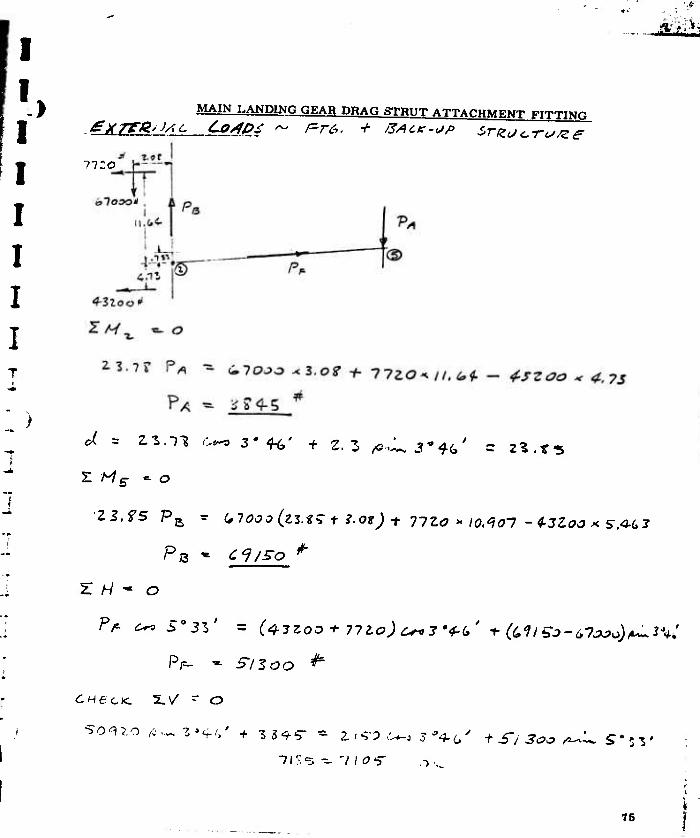
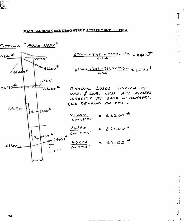
MAIN LANDING GEAR DRAG STRUT ATTACHMENT FITTING
I
Wi Ut.ti
^L jf". rA*j c-'t »i.« »' .SI* .litl . r<J-n «*»(.' .I«.'»« ,/«■(«- .^»r» S' JV .01(7 . öi7n , It«
IS' ,s' .1(1 .111«. .K.«/ S' 4C' .*4*7 .«57 .■»17J
F,4. 54-/
WL loS.n
n/t. ^r.»/
wt ^i.^
PT, F.$. • J(7,4-l t Sn.Tit, J 4-
J it.^
74
M£i
) MAIN LANDING GEAR DRAG STHUT ATTACHMENT FITTINr.
mo
Z Hs ~ o
21.75 P^ ^ ^f000 (zz.t^ f ?.Ot)t -JfZo >- IQ.^i01 -4-3100 <SAG3
Z H ~ o
Fr- C^S03Z' = C4-3Z0O+ 712,o)c^y<f~(,' TfallSo-tfjjJ)^^:
5-53
75
&■■
MAIN LANDING GEAR DRAG STRUT ATTACHMENT FITTING
1
<»/ pf rrz/JC* " P&ee ßo£>y
q-zoo
^u<^«
432-00
4Z2oo
Z7600 ASSUME LOAZS .lf>fc/£o nr L/PZ- $ LUJIZ. COGS /*/za /ZSAcrao
S4-Z.OO _ 4.2,2.00 *■
z^ea - Z 1 boo
76

MAIN LANDING GEAR DRAG STRUT ATTACHMENT FITTING
SC^JJ - 27<icJo T 77os
\0M 4.?t>
PI 3 —-, I-
23,7S S, + {zuioo - -Lnboo) 4.?(. C*<V iC - Hood ^ \\,-?f -^ o
2 3.7?^ -HooO^lZ - * loo (10,27 c~,Z'lL '~n^fi~~t'**'')
S3 - /247o ^
t
1 • -> •L7* a<~ 5'21'
i^;/ JJ
\24t >
OlC
>
77

t^jiii n
MAIN LANDING GEAR DRAG STRUT ATTACHMENT FITTING
Lo*/i=sz l^/es
4-4*100 ^
Z3.fS S^. - 4-<hloo « ,S-| 0^0 is'lS '
.Si o*, S' Z**' ~ S s- ~ ^o* (ZI.ZS - ,S( /Q^'S<'4-C')
2.2.7? S^ - ff/<?c? X4-.7 1 c**(l*>*lf'''2*4*,')*o
/^7 ' <J
/ I t o o
o. /<:.
78

MAIN LANDING GEAR DRAG STRUT ATTACHMENT FITTING
& m *JC £ 0/ij> S
iliso.
/I
-71170
-5407Ö
-lölto
i-no^o
AxtAc LOAO
«»-«»•loo ^wL //'Zt' - ?7(.o*
2.76 -3J .a-w^/f 2« r-i/,
79

MAIN LANDINQ GEAR MOPE CHANGE ACTUATOR SUPPORT FITTINQ
(Drawing 143F129)
The lower and of the mode change actuator la attached to fitting 143F129, which la aupported by the keel and fitting 143F06S. In addition to chang- ing the wheel poaltlon, the actuator acts as a fixed compreaslon link In gear aft landing condltlona. The actuator reacta compreaalon loads In the drag brace when the attaching slider la In the up poaltlon. The cri- tical condition la No. 27 - 9200# G. W., gear aft, two point level aprlng- back. The actuator load la found by equating the vertical component to the vertical component of the drag brace loada.
Limit Drag Brace Load - 9462#
Z Comp. Drag Brace Load = 7325#
(Ref. . Report No. 131, "LANDING GEAR CRITERIA, GROUND LOADS AND REACTIONS " , Page 131.)
2 x 7325 Ultimate Actuator Load = TTTt x 1.5 - 23100* (Comp.) coa 18. 6
The actuator haa been designed for an ultimate compreaalve load of 27000* (Ref. Drawing SCD-L0006). Therefore, the backup structure la alao designed for thia conaervative load.
80

,>
f GEAR POSITIONING ACTUATOR SUPPORT STRUCTURE
Ui.r ACT. LOAö >■ Lioaa
P,
( Re* fco - Loooz)
■/4J r /Z<f
5-. <i Pp - (»,(,r -. szoo
4 ♦
PA » 5-yoj ■*-
P^ ■^ Zioso ^
SP- »- 2.6000 T*
81

FLAP INBOARD HINGE FITTING
(Drawing I43F180)
4*T-
Z8i4 *
4-4-'
1010*
4-^T.*
/OS£> /J/AJZe ^O/M> « Zf/^ * ^^£7=. /?*=T»-r. tieiLt. P. x/evey, coHf. = 2^/^? .v^-i 2 2.-44' ' /o^o^
J
82

4 JACK PAD FITTING
(Drawing 143F061)
The Jack pad fitting la attached to the canted frame @ Fuselage Station 389.7. Critical loads are applied by the airplane wind tunnel supports, and during hoisting.
CA AJTgO PJZAHQ U/*JDTtJjJ/ JL /, SPT. lO*SZ '. A F5 Sff.7
4-500* Doirj/J OK 575 O OP
S'Zoo ~
* qwo *
4.S00
83

V- ' Mt*»«*»-.
THRVPT PPOIL^fi ACTUATOR SUPPORT
(Drawing 143F166)
Ultimate Actuator Load - 5000# (capacity)
GOOd*:
CAurea ff^K/-/'j> /*J s^f. 7
84

•
TAILPIPE AFT SUPPORT
t/CT. t/tsc t-OsiO ■» 47S * (&£/=. £Sf>T. 6Z 8/3/J
^y •-
./i, a 4 * 4 IS- * <17S *■
^ <■ 75" »
./La 4 * f
.0Sir7 * "9 fS7 *
Uo%
s*
V/AJ*. Ho
54-
ILo
1 9<*o'*
5-4.*
4(,o *
85

I 1
PARACHUTE ATTACHMENT STRUCTURE i
Tue parachute attachment atruoture and atorage canister la designed to '. accommodate two typea of parachutea: a 6' diameter, 12 gore, ribleaa * guide surface parachute used for deceleration from high speed or spin recovery, and a 12.75' nominal diameter ring slot parachute used for ; deceleration during landing of the i2F0ü* O. W. configuration or spin recovery in a reefed condition* (Ref. 1 rawing SCD-Q-0002). The maxi- mum load la applied by the smaller parachute during high speed deploy- ment. Loads occurring during apin recovery are also considered, be- cauae the load can be applied at large anglea relative to the airplane longitudinal axia.
High Speed Deceleration Condition;
Ultimate Load = 25000« (g = 850 paf)
ftaln Recovery Condition;
Ultimate Load = 3220* (g = 110 paf)
Load ia applied 30° in vertical plane or 21° in horizontal plane.
* Equivalent drag area = 43.2 aq. ft. in reefed condition.
66

PARACHUTE ATTACHMENT STRUCTURE
Loads Applied to Tail Cone ^Drawing 143F064t
The parachute is attached to the fuselage by a fitting located forward of the tail cone. However, loads are applied to the tail cone by the riser when the angle of the parachute load line is sufficient to cause the riser to bear against the tail cone aft frame. Critical loads applied during spin recovery and reactions at the tail cone splice are shown below.
Riser 30° up in Vertical Plane
y* ß*Af: sw-
S/e* K/<r<v
87

PARACHUTE ATTACHMENT STRUCTURE
Load« ADDlled to Tall Cone
Riaar at 21° in Horizontal Plane
■766 #
88

PARACHUTE ATTACHMENT STRUCTURE
Parachute Attachment Fitting (Drawing 143F1S6)
/ß'tfVf/e sp/tx P-/z*t~fS
Z?40
ZIOC
t.ayio SIT /zy/t) sc/^yocf/z.T Cz.r<io*-J .
89

PARACHUTE ATTACHMENT STRUCTURE
Filing Support Bewn (Pr^iqg |49Ft34)
I2T.OO
■2.S7ÖO
TJE. */> K»*/e &g/lf4*
IStOt^ * T*»- C/fureo 2r*. ITf.C
90

PARACHUTE ATTACHMENT STRUCTURE
91

PARACHUTE ATTACHMENT STRUCTURE
Parachute ReleaBe Meohanlam fDrawlng 143Q001>
The parachute riser la secured to the attachment fitting (143F166) by 143Q003-1 hock which la lock-wired In the UP position after installing the parachute. Initial movement of chute control lever by the pilot rotates 143Q004-1 link to an intermediate position, which locks the hook in the UP position, and also releases the canister cover allowing the chute to be ejected. Additional movement of the control level rotates the link to the full over position, which allows the chute load to break the hook lock-wire. The hook then rotates down and the chute Is re- leased. Loads are shown below for the intermediate position where the link looks the hock. Free-body load diagrams follow.
**JS1 ti-—e©
ZSo&o*' ßlSSIZ L.OAO
j4s c? 003 -1 /yooxr
£ Co\/t=sz /e&Le/isa &&o
/43 <p 004- - / I. /AJ*r
//dc/z f/zs-
0a

PARACHUTE ATTACHMENT STRUCTURE
Releaae MechaniBm
JP/S*'*? S/^qot.
■r*//ce r/ze
ZSOOo
Z4500* f/oa«
nioo
&/cc s/ze
93

PARACHUTE ATTACHMENT STRUCTURE
Release Mechaniam
143Q004-X Link
84