REPAIR TRACK MAINTENANCE - Wabtec Technical …techinfo.wabtec.com/DataFiles/Leaflets/2391,...
36
REPAIR TRACK MAINTENANCE 2391, S.1 2391, S.1 2391, S.1 2391, S.1 2391, S.1 REPAIR TRACK MAINTENANCE 2391, S.1 2391, S.1 2391, S.1 2391, S.1 2391, S.1 APRIL, 1991 (REPRINTED JANUARY, 2002) Freight Air Brake Control Valve Portions: AB TYPE © 2002 WABCO Freight Car Products. A Wabtec Corporation
Transcript of REPAIR TRACK MAINTENANCE - Wabtec Technical …techinfo.wabtec.com/DataFiles/Leaflets/2391,...

REPAIR TRACKMAINTENANCE
2391, S.12391, S.12391, S.12391, S.12391, S.1
REPAIR TRACKMAINTENANCE
2391, S.12391, S.12391, S.12391, S.12391, S.1
APRIL, 1991(REPRINTED JANUARY, 2002)
Freight Air Brake Control Valve Portions:AB TYPE
© 2002 WABCO Freight Car Products. A Wabtec Corporation
2391, S.1
April, 1991 Page 2 of 36
CURRENTLUBRICANT AAR SPECIFICATION
Triple Valve Oil M-912Dry Graphite M-913
Brake Cylinder Lubricant M-914Journal Box Oil M-963
AAR Specifications for lubricants referred to in this publication are as follows:
Air brake shop containers must be stencilled with AAR specifications identification.
Table of Contents
1.0 PROCEDURE FOR CLEANING AND TESTING “AB” TYPE BRAKES ON REPAIR TRACKS ....... 3
1.1 GENERAL REQUIREMENTS ................................................................................................................ 31.2 BODY MOUNTED CYLINDERS ...........................................................................................................111.3 TRUCK MOUNTED CYLINDERS ........................................................................................................ 12
2.0 “AB” CYLINDER REPAIR, IN SHOP ............................................................................................. 16
3.0 ‘UC’ CYLINDER REPAIR, IN SHOP ............................................................................................... 19
4.0 PROCEDURE FOR RECONDITIONING WABCOPAC & NYCOPAC TYPE BRAKE ASSEMBLIES .... 21
5.0 PROCEDURE FOR CLEANING and TESTING “AB-1-B” TYPE BRAKES ON REPAIR TRACKS ....... 27
6.0 PROCEDURE FOR CLEANING AND TESTING EMPTY AND LOAD “AB” TYPE BRAKES ONREPAIR TRACKS ............................................................................................................................ 30
7.0 PROCEDURE FOR CLEANING “AB” TYPE BRAKES THAT HAVE BEEN SUBMERGED ...... 34
8.0 PROCEDURE FOR CLEANING AND TESTING SECONDHAND “AB” TYPE BRAKES PRIORTO REAPPLICATION TO FREIGHT CARS ................................................................................... 35
9.0 RUBBER PARTS, SHELF LIFE, AND STORAGE ......................................................................... 35
Table 1 - AAR Specification for Lubricants

2391, S.1
Page 3 of 36 April, 1991
1.0 PROCEDURE FOR CLEANING AND TESTING “AB” TYPE BRAKES ON REPAIR TRACKS
1.1 GENERAL REQUIREMENTS
1.1.1 Each brake cleaner gang must be provided with a grease can so arranged that both the grease and brush canbe protected against dirt, one extra set of shipping covers for the service and emergency portions of the “AB”Type Control Valve and the retaining valve, a release valve stem guard for “ABD” and ABDW” valve serviceportions, a blower hose and suitable tools such as wrenches, scrapers, clamps, etc. Representative tools arespecified in Figures 16 and 16A.
1.1.2 Record the car number, owner and last cleaning date if required for billing purposes. All old cleaning marksmust be scraped off and painted over with quick drying paint, preferably black.
1.1.3 Close the branch pipe cock and drain the air out of the auxiliary reservoir, emergency reservoir and brakecylinder. Remove the cup from the dirt collector and leave it off until cleaned valve portions are applied. Disconnectthe release valve handle or handles, leaving attached to the release rod or rods.
1.1.4 Blow any dirt or water out of the yard air line and supply hose connection to car. If the brake tests are to bemade by the same men who clean the brake, couple the single car testing device to yard air line and car brakepipe at one end of car. Otherwise, couple the yard air supply directly to the car brake pipe. Charge brake pipeand leave yard air supply connected to it. Blow out the brake pipe by opening angle cock at opposite end of car,then apply a dummy coupling to this end and leave both angle cocks open. Open the branch pipe cock to blowdirt from the branch pipe, then close it.
Figure 1 - Views of AB Type Control Valves Showing the Operating Portions and Pipe Bracket
“AB” Control Valve “ABD” Control Valve
“ABC-1” Control Valve “ABDW” Control Valve

2391, S.1
April, 1991 Page 4 of 36
Figure 2 - AB Control Valve Service Portion with Shipping Cover and Inside View of the Cover
Figure 3 - AB Control Valve Service Portion with Old Style Shipping Cover and Inside Views of the Cover
Figure 4 - ABD Control Valve Service Portion with Shipping Cover and Inside View of the Cover

2391, S.1
Page 5 of 36 April, 1991
1.1.5 Scrape, wipe and blow off all dirt adjacent to the gaskets between the pipe bracket and the valve portions, then,using the blower hose, blow off all loose dirt on the control valve portions, pipe bracket, hopper slopes, carunderframes, etc., that may otherwise get into the control valve portions or bracket when the portions are beingremoved and cleaned portions applied.
1.1.6 The operating portions or parts thereof must never be dismantled or have any parts removed or replaced (unlessauthorized by AAR Interchange Rule) at the car. All cleaning and relubricating of the valve portion parts must bedone by a competent workman at a suitable bench in a clean, well-lighted location.
1.1.7 Remove the vent protector from the emergency portion and apply a manufacturer’s standard or alternate ventprotector plug, a shown in Figure 7, then remove the emergency portion and, after moving the piston (“AB” only)into release position, immediately apply to it the spare shipping cover and tighten its holding nuts. The emergencyportion must be carefully handled to avoid entrance of dirt, water or damage to internal parts.
1.1.7.1 Remove the service portion and the pipe bracket strainer. Apply shipping cover to the service portion and tightenits holding nuts. The service portion must be carefully handled to avoid entrance of dirt, water or damage tointernal parts. Apply standard or alternate stem guard (Figure 5) to ABD & ABDW portions and hold in placewith cotter pin. Pipe bracket strainer on Control Valves must be renewed.
Figure 4.1 - Alternate Approved Shipping Covers
Figure 5 - Release Valve Stem Guards
Service Portion Emergency Portion
Standard Alternate Standard

2391, S.1
April, 1991 Page 6 of 36
1.1.8 If the car is equipped with a brake cylinder release valve, disconnect the handle, leaving it attached to therelease rods. Clean adjacent areas as with control portions. Remove the brake cylinder release valve from thepipe bracket or adapter and immediately apply shipping cover and tighten holding nuts.
1.1.8.1 If the car is equipped with empty and load type of equipment, the component parts such as the changeoverportion, the strut cylinder, the transfer valve portion, the cutoff valve portion, the relay valve and the pilot valveportion, the check valve case, the L-1 Detector Valve portion, the S-1 Load Sensor Valve portion and the P-1Load Proportional Valve portion must be removed. Clean adjacent area as with the control valve portions, then,remove the portion. Apply shipping covers where provided and transport to the shop for maintenance. Theprocedure specified beginning in Paragraph 1.1.14 must be followed when portions are remounted. The L-1Detector Valve and the S-1 Load Sensor Valve adjustments are made at the time of Single Car Test.
1.1.9 If the car is equipped with either a quick service valve, vent valve, or reduction relay valve, clean adjacent areasas with control portions, then remove the valve portions.
1.1.10 If the car is equipped with a “J” type relay valve, clean adjacent areas as with control portions, then remove thevalve portion. Immediately apply the shipping cover to relay valve and tighten its holding nuts.
Figure 6 - Shipping Cover for Retaining Valve Figure 7 - Vent Protector Plugs
Figure 8 - S-1 Load Sensor Valve Figure 9 - P-1 Lead ProportionalValve
Figure 10 - L-1 Detector Valve
Alternate Standard Standard

2391, S.1
Page 7 of 36 April, 1991
NOTE: The valve portions removed from car must be transported to the shop for cleaning, lubricating and testing, inaccordance with current Issue of Instruction Leaflets No. 2391, Sup. 3 and manufacturer’s specifications.
1.1.11 If car is equipped with a reservoir charging check valve (mounted on “AB” Type Pipe Bracket), remove the capnut, spring and check valves. Examine the internal parts for excessive wear or damage and replace if necessary.Reassemble the check valve.
1.1.12 Using scrapers of suitable form, loosen any dirt in the brake pipe passages, strainer chamber and otherconnecting passages of the pipe brackets and adapter, if used, then, using the blower hose fitted with a nozzleshown as No. 7 on Figure 16, remove any loose dirt and scale from the retaining valve bracket and pipe byblowing from both the pipe brackets, adapter, if used, and retaining valve ends, blow the dirt from face of thebrackets, also strainer chambers and branch pipe passage toward the open dirt collector.
1.1.13 When the valve portions are removed and conditions are found in the portions or the pipe brackets evidencingthat the car brake equipment has been submerged in water, special additional cleaning operations not regularlyperformed will be required as directed in Section 7.
Figure 11 - AB Control Valve Emergency Portionwith Shipping Cover and Inside View of Cover
Figure 12 - ABD Control Valve Emergency Portionwith Shipping Cover and Inside View of Cover
Figure 13 - Shipping Cover for BrakeCylinder Release Valve
Figure 13.1 - View of A-2-A Quick ServiceValve and Shipping Cover

2391, S.1
April, 1991 Page 8 of 36
1.1.14 Pipe bracket gaskets on Control Valves (both portions) must be removed and replaced with new gaskets.
1.1.15 The shipping cover must not be removed from the clean emergency portion until prepared to mount the portionon the pipe bracket. With the service and emergency portion gaskets in place on the pipe bracket and fullyseated at their locking projection, remove the shipping cover from the clean emergency portion. Inspect emergencypiston (“AB” only) to insure that it is in release position. Damage to the piston and bush will result if piston isout of the bush while portion is mounted on the pipe bracket. Immediately mount the portion, sliding it slowlyand carefully on the studs against the pipe bracket, then, after coating the threads lightly with brake cylinderlubricant, or a compound consisting of one part graphite and two parts of oil (SAE-20) by weight, tighten itsholding nuts evenly and then firmly.
NOTE: When reassembling valve portions or individual valve portions to their respective pipe brackets, it is importantthat cap screws and nuts are sufficiently tightened to prevent gasket leakage and yet not excessively to causedistortion of covers and gaskets.
Clean, or renew, if necessary, the vent protector, then remove the vent protector plug and apply and securelytighten protector to the cleaned emergency portion.
1.1.16 Pipe bracket strainer on control valves must be renewed. A wood mandrel of suitable form will assist in guidingthe strainer into proper position. Make certain its inner end is in engagement with the sealing bead (if insertedproperly, all nut threads will be visible), then apply its holding nut and tighten it firmly with the special wrenchprovided. Next, remove the shipping cover from the clean service portion, and with the piston (“AB” only) inrelease position, immediately apply the portion to the pipe bracket and, after coating the threads lightly withbrake cylinder lubricant or a compound consisting of one part graphite and two parts of oil (SAE-20) by weight,tighten its holding nuts evenly and then firmly. The shipping cover must not be removed from the clean serviceportion until prepared to mount the portion on the pipe bracket. Remove stem guard. (“AB”)
1.1.17 If car is equipped with a brake cylinder release valve, remove the shipping cover from the clean valve portion andimmediately apply the latter to its respective mounting face. The shipping cover must not be removed from theclean brake cylinder release valve portion until prepared to mount the portion on the pipe bracket or adapter, ifused.
Figure 14 - J-1 Relay Valve Figure 15 - Views of Reduction Relay Valves

2391, S.1
Page 9 of 36 April, 1991
Figure 16A - Air Brake Cleaner’s Repair Track Tools
Figure 16 - List of Air Brake Cleaner’s Tools
PRINCIPALNO. TOOL PURPOSE DIMENSION
1 Reversible Ratchet 1/2” sq. drive for all sockets (Plated) 101/2” long2 Extra Deep Socket For 1/2” cap screw, Flange Fittings 3/4” hex opening3 Extra Deep Socket For 3/8” cap screw, Flange Fittings 9/16” hex opening4 1” Socket For 3/8” nuts - Service & Emerg. Portions 1” hex opening
4A 15/16” Socket For 5/8” nuts - Service & Emerg. Portions 15/16” hex opening5 13/16” Socket For 1/2” nuts - “AB” Empty & Load Change-Over 13/16” hex opening
Valves5A 3/4” Socket For 1/2” nuts - “AB” Empty & Load Change-Over 3/4” hex opening
Valves6 5/8” Socket For 3/8” nut on non-pressure head of Brake Cyl. 5/8” hex opening
6A 9/16” Socket For 3/8” nut on non-pressure head of Brake Cyl. 9/16” hex opening7 Nozzle (1/4” extra heavy pipe) For No. 10 8” long
8A Strainer nut For various types of strainers8B Wrench9 Universal Joints Used with ratchet, sockets and extension bars10 Blowing Nozzle Valve For blowing off complete equipment and ports
(E Type) in “AB” pipe bracket11 Double Ended Wrench For 1/2” bolts and cap screws on dirt collector 13/16” & 3/4”
“S” open end12 Short Extension Bar Used with ratchet, sockets and universal joint 51/4” long13 Long Extension Bar 101/2” long

2391, S.1
April, 1991 Page 10 of 36
1.1.18 If car is equipped with either a quick service valve, vent valve or reduction relay valve, apply clean valve portionto pipe bracket after new strainer is applied. Orifice 3/64” drill plug in A-2-A Pipe Bracket must be clear ofobstruction and the proper size. Choke plugs in B-1 Quick Service Valve face of pipe bracket must be clear ofobstruction and proper size (See Fig. 17). When the car (75 ft. and over in brake pipe length) is on the repair orshop track for periodic COT&S, air brake equipment attention, Choke “B”, Part No. 94033, with a #62 drillchoke must be removed and replaced with Part No. 578254 with a #54 drill choke. Stamp pipe bracket bodywith 1/4” high letter “X” as shown (See Fig. 17) to permanently indicate that the modification has been made.
1.1.18.1 If car is equipped with a “J” type relay valve, remove the shipping cover from the clean valve portion andimmediately apply the latter to its respective mounting face. The shipping cover must not be removed from theclean relay valve portion until prepared to mount the portion on the pipe bracket.
NOTE: Following Paragraph 1.1.19 is to be disregarded if car is equipped with older type pressure retaining valve.
1.1.19 Insert a new strainer properly into the pipe bracket, then, with the gasket firmly in place, immediately attachretaining valve to pipe bracket and fasten securely in place with the two cap screws. The shipping cover mustnot be removed from a new or cleaned retaining valve until prepared to mount device on its pipe bracket.
1.1.20 Reconnect the release valve handle or handles (which has been left attached to release rod) to release valvehandle end plate with a 3/16” cotter. Note that a 5/16” cotter is provided to connect rod to handle, if not, replacewith a 5/16” cotter.
Clean and blow out the dirt collector dirt chamber. Clean the check valve. Renew the gasket, then assemble,lubricating the bolt threads lightly with brake cylinder lubricant AAR Specification M-914, or a compoundconsisting of one part graphite AAR Specification M-913 and two parts of oil (SAE-20) by weight.
1.1.21 Check the cylinder, reservoir and pipe bracket for loose supporting bolts and nuts and if missing or loose, theymust be renewed or tightened. Tighten all flange pipe fittings solidly.
1.1.22 Replace retaining valve with new or reconditioned 3-position retaining valve. Application of appropriate pipebracket may be required.
1.1.23 Brake cylinders must be cleaned as described in Sections 1.2 and 1.3.
Figure 17 - B-1 Quick Service Valve - Pipe Bracket Choke Arrangement
AB
C
X* Measured along the pipe between
end hose couplings.
• Not required on cars with less than75 feet of brake pipe length.
Car Length Port “A” Port “B” Port “C”
• UNDER 0.081 0.0635 0.1520* 75 FT. #46 drill #52 Drill #24 Drill
75 FT. or None 0.055 NoneLONGER * #54 Drill
Steel Stamp Pipe Bracket with1/4” High Letter “X” as Shown.

2391, S.1
Page 11 of 36 April, 1991
1.1.24 The entire air brake equipment must be tested as required by the current issue of test codes for single cartesting device (5039-4 Sup. 1), including brake cylinder leakage, retaining valve tests and piston travel. SLACKADJUSTERS on cars so equipped must be inspected and repaired or renewed when necessary. Repairs whenrequired must be make in accordance with the specific manufacturer’s maintenance recommendations. Note ifany pipe clamps are loose or missing, or if the angle cocks are improperly located, and make any neededrepairs. Apply new gaskets to both brake pipe hose couplings.
1.1.25 APPLY NEW C.O.T. & S. DATE WITH A STENCIL AFTER ALL WORK HAS BEEN COMPLETED.
1.1.26 REPRESENTATIVE TOOLS AND EQUIPMENT ARE NECESSARY FOR THE BRAKE CLEANER FORPERFORMING THE WORK AS ABOVE DIRECTED. To secure the required external clearances and strengthand reduce the cleaning time to a minimum, the tools are specially designed and made of high tensile steel.They may be obtained from the brake manufacturers.
1.1.27 Suitable covers or containers to protect the brake cylinder piston, hollow rod and non-pressure head assembliesfrom dirt or damage should be provided when transporting assemblies to and from the car.
1.2 BODY MOUNTED CYLINDERS
1.2.1 Drain air from all reservoirs and brake cylinders. Disconnect and remove the brake cylinder push rod. To avoidpersonal injury which may occur if the non-pressure head assembly is not secured by the hollow rod collar,examine the collar to determine that it will hold securely, then remove the piston, release spring and non-pressure head complete.
NOTE: The non-pressure head of the “UC” Type Brake Cylinder can be removed from the brake cylinder providing thehollow rod collar is retained in position.
These parts must be transported to a suitable shop for reconditioning. The piston assembly must be handledat the car and while being transported to and from the car, so that the piston packing cup, lubricator swabassembly and other parts will be effectively protected against damage and contact with any kind of dirt. It willbe the responsibility of individual railroads to provide such adequate protective means.
1.2.2 Remove non-pressure head and gasket, clean its seat when cleaning the brake cylinder and apply new gasketwhen assembling cylinder.
1.2.3 Thoroughly clean the brake cylinder by first using a dull rounded scraper for removal of all grease and any dirt.Use a suitable solvent, if necessary, to soften gummy deposits and remove rust spots, then wipe dry and cleanwith rags. When the cylinder is cleaned, unless the cleaner is prepared to immediately apply the piston andnon-pressure head assembly, the cylinder should be covered to protect it from dust and dirt. The lubricantshould be applied to the cylinder just before the cleaned and lubricated piston is installed. Packing cups mustbe renewed. “ABD/ABDW” equipped cars must be equipped with non-pressure head and integral return springguide and designed to utilize the latest type hollow rod packing seal.
1.2.4 Coat the cylinder wall bearing surface of the packing cup and fill the grease groove of the swab retainer withbrake cylinder lubricant. Immediately apply these parts to the cylinder making sure that the non-pressure headexhaust and strainer is located in the down position and tighten the non-pressure head bolts. Apply andconnect the push rod. DO NOT INTENTIONALLY APPLY LUBRICANT TO THE DOME SECTION OF THEPACKING CUP OR THE PRESSURE HEAD OF THE CYLINDER.

2391, S.1
April, 1991 Page 12 of 36
1.3 TRUCK MOUNTED CYLINDERS
NOTE: For truck mounted brake assemblies other than WABCOPACand NYCOPAC Brake Units covered herein, refer to specificmanufacturer’s maintenance recommendations
1.3.1 Drain air from all reservoirs and brake cylinders.
Work done at car is best accomplished by disconnection brakecylinder hoses at cylinder flanges and hand brake chain, thenjacking the car and rolling truck out. While working on truck,wheels should be chocked to prevent unwanted roll. If work canbe done with car over a pit or depressed area between rails,jacking of car is not required. When hoses are disconnected,inspect hoses for abrasion, cracks, soft spots, and loose ordefective fittings.
Remove brake shoes.
If any cylinders and/or levers are found damaged or missing refer to car badge plate (See Fig. 24) for correctcylinders and lever sizes.
Any welding found necessary must be done in compliance with manufacturer’s instructions and specifications.
Remove old brake cylinder and piston assemblies for cleaning by the following procedure:
Examine push rod holder to determine that it is securely in place (See Fig. 18). Should it be missing orinsecure, caution must be exercised in removing the brake cylinder body since it is spring loaded and will tendto “spring” toward the axle.
Remove cotter pin, then remove push rod pin.
Push brake unit body toward bolster, using two wrenches loosen push rod locking nut, then remove push rodand place on bolster. If push rod is damaged, return it to shop for repair and replace with one of the same length.
Remove brake cylinder nuts and bolts. Remove cylinder and piston assembly and transport assembly to shopfor cleaning, upgrading and lubricating in accordance with Section 4.0. Protect assembly from damage andcontamination during handling to and from shop.
1.3.2 Apply cleaned brake cylinder assemblies as follows:
Remove brake cylinder gasket. Clean rust and other dirt frombolting face (See Fig. 19).
Clean spring cavity and renew strainer in unit body.
Make certain hollow rod guide gasket of hollow rod guide is inplace, align spring seat stop and cylinder flange bolt holes withthose of the unit body making certain spring seat stop drain holeis facing downward. Position the assembly in the unit body cavityand start nuts on top bolts. Position the hollow rod guide in theunit body recess by grasping the push rod end and shifting untilrelease spring pushes guide into place (See Fig. 20). Install lowerbolts and tighten all nuts evenly and securely.
Figure 18
Figure 19

2391, S.1
Page 13 of 36 April, 1991
NOTE 1: Use a thin film of brake cylinder lubricant on both sides of springseat stop flange and on unit body bolting face to hold gaskets inplace.
NOTE 2: Six-bolt cylinders are not interchangeable with those used infour-bolt assemblies. Care should be exercised to avoid animproper application when replacing six-bolt details. Clean pushrod threads and lubricate with brake cylinder lubricant thenreplace push rod. +Turn push rod into push rod end two (2)turns beyond the mark previously placed on push rod, align pinholes in push rod with pin holes in brake unit bodies, then insertpins and lock with cotter pins (See Fig. 21).
+NOTE: Push rods on new installations should also be lubricated asabove before assembly into brake cylinder push rod end.
1.3.3 Piston Travel Adjustment - Must be performed on new cars, after COT&S, after any new or turned wheelreplacement on affected truck, and after truck replacement.
Insert spacing blocks, shown on Fig. 23, between brake heads of both unit bodies and four (4) wheels as closeas possible to the flange (See Fig. 22). If push rod adjustment is necessary to permit spacing block insertion,rotate the push rod end to shorten the push rod (when facing the bolster from the pressure end of brake cylinderand with wrench handle upward, moving the wrench handle to the right will shorten the rod and moving to the leftwill lengthen the rod).
Adjust both push rods to snug spacing blocks against wheels by rotating both push rod ends to lengthen pushrods. After both push rods have been snugged with spacing blocks against wheels, rotate both push rod ends½ turn to the right to shorten the rod for easy spacing lock removal.
Remove spacing blocks and mount shoes. If new shoes are mounted, use only 11/4” or 11/2” thick shoes.
Tighten push rod locking nut securely (Use two wrenches).
Reinstall truck under car, remove hose fitting flange face protection making certain that the strainer is in place(if cylinder is so equipped). Renew hose flange fitting gaskets, then connect brake cylinder hoses. Also (onhand brake truck) apply hand brake chain and pull rod at hand brake levers and install cotter pins. The correctpiston travel with all new shoes per truck is 11/4” for 11/4” thick shoes and 3/4” for 11/2” thick shoes.
Figure 20
Figure 21 Figure 22

2391, S.1
April, 1991 Page 14 of 36
1.3.4 Hand Brake Adjustment - Perform on New Cars,After Any New or Turned Wheel Replacementsand After Truck Replacements.
Adjustment of the hand brake is not normallyrequired unless truck wheels have been replaced.The following procedure will allow for properadjustment at such time. Refer to Fig. 24.
(a) Release hand brake fully. The horizontal hand brakechain should have minimal slack. If so, hand brakeadjustment is proper. If not so, follow to “b”
(b) Disconnect adjustment pin at anchor clevis. Pullon pull rod by hand and insert pin in farthest holepossible. If this brings horizontal chain to haveminimal slack, slack adjustment is proper. If thechain is still loose, move back one (1) hole, thenmake adjustment at bottom rod as in “c”.
(c) If necessary, as in “b”, move pin at one end of bottom rod to outside hole. This should bring horizontal chaintaut. If not, tighten chain at anchor clevis as in (a) and (b).
NOTE: Movement of the pin at the anchor clevis one hole toward the body anchor will shorten the horizontal chaintravel approximately 3”. Movement of the pin at the bottom rod one hole towards the end of the rod will shortenthe chain travel 43/8”.
PROCEDURE FOR RECONDITIONING AND TESTING BRAKE CYLINDER PISTONS AND ASSOCIATEDPARTS IN THE SHOP
Figure 23 - Suggested Hardwood Spacing Blocks
Figure 24 - Hand Brake Adjustment
The Brake Assembly Hand Brake can be adjusted to compensate for shoe and wheel wear through pin connections at the connecting rod and the anchor clevis. The connecting rod length can be variedby means of the two holes, 13/4” apart at each end (Ref. “A” & “B”). The anchor clevis can also be adjusted in this manner. It contains two holes 3” apart (Ref. “K” &”L”) for maximum adjustments.
The above table shows the adjustments that are obtained by connecting these holes in accordance with the letter code indicated.
Anchor Clevis
Connecting Rod
ToAnchor
ToHandBrake
A
A
B
BHL
K
The car badge plate serves to identify the size of the cylinder (“E”), theconnecting rod length (“C”), and fulcrum lengths for the levers (“A” & “B”).
EQUIVALENTCONNECTION COMPENSATION HORIZONTAL
CODE AT EACH SHOE CHAIN TRAVEL
HLAA Normal NormalHKAA 7/16” 3”HLBA 5/8” 43/8”HKBA 11/16” 73/8”HLBB 11/4” 83/4”HKBB 111/16” 113/4”
Anchor Clevis
33/8”
41/8”
5/8” 15/8”
5/8”7/8”
1/8”
3/4”1/4”
11/8”
3/8”15/8”
90° 90°
1/8”1/8”
11/2”
13/8”
1/16”
HANGER
SIDE
1/8”
1/16”
4 ”
1/16”
1/8”
1/16”
3/16”
17/8”
17/ 32
”
3/4” 3/4”
17/32”
* Drilled to Fit Hanger Hole Screws
Handle Material - 1/16” Flat Stock
Block Material - Hardwood, Prefer Maple

2391, S.1
Page 15 of 36 April, 1991
Figure 25 - Representative Tools for Reconditioning Brake Cylinder Pistons and Associated Parts
PRINCIPALNO. TOOL PURPOSE DIMENSION PART NO.14 Hinged Off-Set Handle For Non-Pressure Head Assembly 3/8” Lock 51307415 3/8” Socket For Non-Pressure Head Assembly 3/8” hex opening 51307116 7/16” Socket Non-Pressure Head Assembly 7/16” hex opening 51307217 1/2” Socket Non-Pressure Head Assembly 1/2” hex opening 51307318 Compression Ring Used to apply brake cylinder 513075
Assembly Tool hollow rod lubricator19 Hollow Rod Packing Used to Apply Hollow Rod Packing 13 1/4” Long 526333
Seal and Retainer Seal and RetainerAssembling Sleeve

2391, S.1
April, 1991 Page 16 of 36
2.0 “AB” CYLINDER REPAIR, IN SHOP
2.1 DISASSEMBLY
2.1.1 Piston packing cup and strainer on brake cylinders must be removed and replaced with a new piston packingcup and strainer.
Non-pressure heads used with “ABD” and “ABDW” Control Valves must have integral return spring guide andmust use latest type hollow rod packing seal.
2.1.2 Remove the swab retainer. Plastic guide rings (See Fig. 27) must not be removed or replaced unless worn topiston diameter.
NOTE: If piston is equipped with a lubricator swab, the swab must be removed and omitted from future assembly. (SeeFig. 26).
Clean the piston guide ring or swab retainer with a suitable solvent.
2.1.3 Place the piston and non-pressure head assembly in a holding fixture, which will hold the release springpartially compressed, and proceed as follows:
2.1.4 LUBRICATOR SWAB OR METAL RING-PACKED ON-PRESSURE HEAD
NOTE: The metal rings and adjacent lubricator swab may be substituted by lubricator swab, if so desired. (See Fig. 28).
(a) Remove the hollow rod collar, the lubricator swab or seal ring retaining plate, lubricator swab or seal rings,lubricator swab and swab compression ring.
Then remove the non-pressure head and the release spring from the hollow rod. Remove the strainer.
(b) Blow all of the dirt out of the non-pressure head and at the same time blow any loose dirt from the strainercavity. Apply new strainer.
Figure 26 - Partial Section of Brake CylinderShowing the Swab Retainer
Figure 27 - Partial Section of Brake CylinderShowing the Piston Ring Guide
2391, S.1
Page 17 of 36 April, 1991
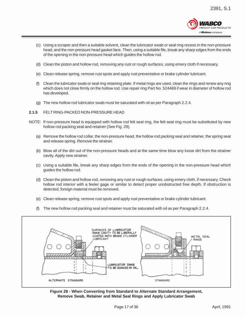
(c) Using a scraper and then a suitable solvent, clean the lubricator swab or seal ring recess in the non-pressurehead, and the non-pressure head gasket face. Then, using a suitable file, break any sharp edges from the endsof the opening in the non-pressure head which guides the hollow rod.
(d) Clean the piston and hollow rod, removing any rust or rough surfaces, using emery cloth if necessary.
(e) Clean release spring, remove rust spots and apply rust preventative or brake cylinder lubricant.
(f) Clean the lubricator swab or seal ring retaining plate. If metal rings are used, clean the rings and renew any ringwhich does not close firmly on the hollow rod. Use repair ring Part No. 524469 if wear in diameter of hollow rodhas developed.
(g) The new hollow rod lubricator swab must be saturated with oil as per Paragraph 2.2.4.
2.1.5 FELT RING-PACKED NON-PRESSURE HEAD
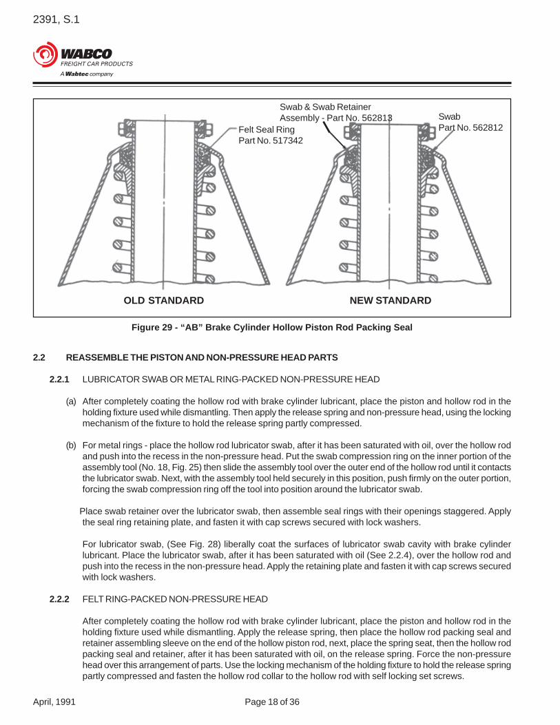
NOTE: If non-pressure head is equipped with hollow rod felt seal ring, the felt seal ring must be substituted by newhollow rod packing seal and retainer (See Fig. 29).
(a) Remove the hollow rod collar, the non-pressure head, the hollow rod packing seal and retainer, the spring seatand release spring. Remove the strainer.
(b) Blow all of the dirt out of the non-pressure heads and at the same time blow any loose dirt from the strainercavity. Apply new strainer.
(c) Using a suitable file, break any sharp edges from the ends of the opening in the non-pressure head whichguides the hollow rod.
(d) Clean the piston and hollow rod, removing any rust or rough surfaces, using emery cloth, if necessary. Checkhollow rod interior with a feeler gage or similar to detect proper unobstructed free depth. If obstruction isdetected, foreign material must be removed.
(e) Clean release spring, remove rust spots and apply rust preventative or brake cylinder lubricant.
(f) The new hollow rod packing seal and retainer must be saturated with oil as per Paragraph 2.2.4.
Figure 28 - When Converting from Standard to Alternate Standard Arrangement,Remove Swab, Retainer and Metal Seal Rings and Apply Lubricator Swab
2391, S.1
April, 1991 Page 18 of 36
2.2 REASSEMBLE THE PISTON AND NON-PRESSURE HEAD PARTS
2.2.1 LUBRICATOR SWAB OR METAL RING-PACKED NON-PRESSURE HEAD
(a) After completely coating the hollow rod with brake cylinder lubricant, place the piston and hollow rod in theholding fixture used while dismantling. Then apply the release spring and non-pressure head, using the lockingmechanism of the fixture to hold the release spring partly compressed.
(b) For metal rings - place the hollow rod lubricator swab, after it has been saturated with oil, over the hollow rodand push into the recess in the non-pressure head. Put the swab compression ring on the inner portion of theassembly tool (No. 18, Fig. 25) then slide the assembly tool over the outer end of the hollow rod until it contactsthe lubricator swab. Next, with the assembly tool held securely in this position, push firmly on the outer portion,forcing the swab compression ring off the tool into position around the lubricator swab.
Place swab retainer over the lubricator swab, then assemble seal rings with their openings staggered. Applythe seal ring retaining plate, and fasten it with cap screws secured with lock washers.
For lubricator swab, (See Fig. 28) liberally coat the surfaces of lubricator swab cavity with brake cylinderlubricant. Place the lubricator swab, after it has been saturated with oil (See 2.2.4), over the hollow rod andpush into the recess in the non-pressure head. Apply the retaining plate and fasten it with cap screws securedwith lock washers.
2.2.2 FELT RING-PACKED NON-PRESSURE HEAD
After completely coating the hollow rod with brake cylinder lubricant, place the piston and hollow rod in theholding fixture used while dismantling. Apply the release spring, then place the hollow rod packing seal andretainer assembling sleeve on the end of the hollow piston rod, next, place the spring seat, then the hollow rodpacking seal and retainer, after it has been saturated with oil, on the release spring. Force the non-pressurehead over this arrangement of parts. Use the locking mechanism of the holding fixture to hold the release springpartly compressed and fasten the hollow rod collar to the hollow rod with self locking set screws.
Figure 29 - “AB” Brake Cylinder Hollow Piston Rod Packing Seal
OLD STANDARD NEW STANDARD
Felt Seal RingPart No. 517342
Swab & Swab RetainerAssembly - Part No. 562813 Swab
Part No. 562812
2391, S.1
Page 19 of 36 April, 1991
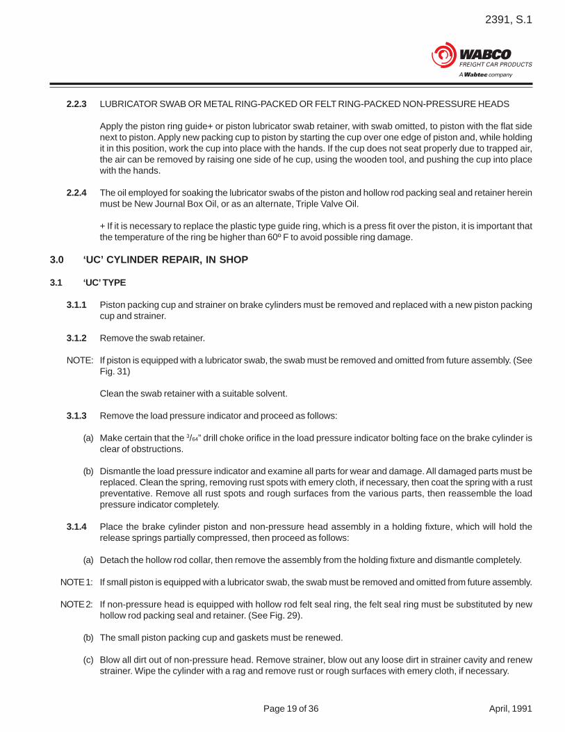
2.2.3 LUBRICATOR SWAB OR METAL RING-PACKED OR FELT RING-PACKED NON-PRESSURE HEADS
Apply the piston ring guide+ or piston lubricator swab retainer, with swab omitted, to piston with the flat sidenext to piston. Apply new packing cup to piston by starting the cup over one edge of piston and, while holdingit in this position, work the cup into place with the hands. If the cup does not seat properly due to trapped air,the air can be removed by raising one side of he cup, using the wooden tool, and pushing the cup into placewith the hands.
2.2.4 The oil employed for soaking the lubricator swabs of the piston and hollow rod packing seal and retainer hereinmust be New Journal Box Oil, or as an alternate, Triple Valve Oil.
+ If it is necessary to replace the plastic type guide ring, which is a press fit over the piston, it is important thatthe temperature of the ring be higher than 60º F to avoid possible ring damage.
3.0 ‘UC’ CYLINDER REPAIR, IN SHOP
3.1 ‘UC’ TYPE
3.1.1 Piston packing cup and strainer on brake cylinders must be removed and replaced with a new piston packingcup and strainer.
3.1.2 Remove the swab retainer.
NOTE: If piston is equipped with a lubricator swab, the swab must be removed and omitted from future assembly. (SeeFig. 31)
Clean the swab retainer with a suitable solvent.
3.1.3 Remove the load pressure indicator and proceed as follows:
(a) Make certain that the 3/64” drill choke orifice in the load pressure indicator bolting face on the brake cylinder isclear of obstructions.
(b) Dismantle the load pressure indicator and examine all parts for wear and damage. All damaged parts must bereplaced. Clean the spring, removing rust spots with emery cloth, if necessary, then coat the spring with a rustpreventative. Remove all rust spots and rough surfaces from the various parts, then reassemble the loadpressure indicator completely.
3.1.4 Place the brake cylinder piston and non-pressure head assembly in a holding fixture, which will hold therelease springs partially compressed, then proceed as follows:
(a) Detach the hollow rod collar, then remove the assembly from the holding fixture and dismantle completely.
NOTE 1: If small piston is equipped with a lubricator swab, the swab must be removed and omitted from future assembly.
NOTE 2: If non-pressure head is equipped with hollow rod felt seal ring, the felt seal ring must be substituted by newhollow rod packing seal and retainer. (See Fig. 29).
(b) The small piston packing cup and gaskets must be renewed.
(c) Blow all dirt out of non-pressure head. Remove strainer, blow out any loose dirt in strainer cavity and renewstrainer. Wipe the cylinder with a rag and remove rust or rough surfaces with emery cloth, if necessary.

2391, S.1
April, 1991 Page 20 of 36
Figure 30 - “UC” Type Brake Cylinder Figure 31 - “U” Type Brake Cylinder Redesigned toEliminate Lubricator Swab
Figure 32 - WABCOPAC and NYCOPAC Brake Cylinder Assemblies
OLD STANDARD
NEW STANDARD
RIVETED TYPE
MAGNEFORMED TYPE

2391, S.1
Page 21 of 36 April, 1991
(d) Using a suitable file, break all sharp edges from the ends of the openings in the spring cage, spring guide andspring seat.
(e) Clean pistons, piston tube, release spring and hollow rod, removing rust or rough surfaces. Use emery cloth, ifnecessary, to give satisfactory results.
(f) The new hollow rod packing seal and retainer must be saturated with oil as per Paragraph 2.2.4.
3.2 Reassemble the piston and non-pressure head
(a) Coat the hollow rod and piston tube as well as the release spring and cylinder walls and the sealing peripheryof the packing cup with brake cylinder lubricant. DO NOT INTENTIONALLY APPLY LUBRICANT TO THEDOME SECTION OF THE PACKING CUP OR THE PRESSURE HEAD OF THE CYLINDER. Place the pistonand hollow rod assembly in the holding fixture used while dismantling. Place the release springs and pistonguide in position, then place the spring seat and the hollow rod packing seal and retainer, after it has beensaturated with oil (See 2.2.4), on the release spring. Attach the spring cage to the non-pressure head, thenplace the non-pressure head over the piston and spring assembly. Use the holding fixture to partly compressthe release springs and fasten the hollow rod collar to the hollow rod with self locking set screws.
(b) Apply piston lubricator swab retainer, with swab omitted, to piston with the flat side next to piston. Applypacking cup to piston by starting the cup over one edge of the piston, then, while holding it in this position, workthe cup into place by hand. If the cup does not seat properly due to trapped air, the air can be released byraising one side of the cup, using the wooden tool, then pushing the cup into place by hand.
3.2.1 Mount cleaned load pressure indicator on the non-pressure head, making certain that the mounting face iswiped clean and the gasket is in place.
4.0 PROCEDURE FOR RECONDITIONING WABCOPAC & NYCOPAC TYPE BRAKE ASSEMBLIES
4.1 DISASSEMBLY
4.1.1 Lift and remove piston hollow rod assembly from brake cylinder.
(a) Remove packing cup by using a wooden tool about 1” wide and 3/32”thick, or equivalent, with rounded edges to prevent damage to guidering.
(b) Do not remove piston guide ring unless worn to piston diameter.
4.1.2 Place piston hollow rod assembly in holding fixture and partially compressrelease spring by contacting the hollow rod guide, then remove set screwsand push rod holder (See Fig. 33).
4.1.3 Remove piston hollow rod assembly from holding fixture, then remove hollowrod guide gasket, hollow rod guide, o-rings, hollow rod packing seal, springseat, spring seat stop, gasket and release spring.
4.1.4 SCRAP WABCOPAC RIVETED HOLLOW ROD ASSEMBLIES (WITH ORWITHOUT KEEPER PINS). SCRAP (OR WELD*) ALL MAGNEFORMEDPISTON ASSEMBLIES WHICH DO NOT HAVE THE LETTERS “PF” OR“PFS” ON THE PISTON (AS SHOWN ON FIGURE 35) AND HAVE NOTBEEN WELDED. SEE TABLE 2 ON PAGE 27. Figure 33

2391, S.1
April, 1991 Page 22 of 36
Figure 34 Figure 35
Figure 36 - Assembling Sleeve
WABCO NYABCO
PFor
PFS

2391, S.1
Page 23 of 36 April, 1991
*NOTE: Magneformed pistons can be salvaged by welding as per instructions in WABCO brochure No. 9013-7, titledWABCOPAC Brake Assembly, dated November 1978.
4.1.5 Disassemble Piston Hollow Rod Assembly
(a) Straighten lock ring, then use spanner wrench shown on Fig. 40 to remove lock plug and lock ring from piston.
NOTE: To avoid hollow rod damage when disassembling or assembling lock plug piston hollow rod assembly must berestrained from rotation at lugs on underside of piston (See Fig. 41 - Fixture on Fig. 42 and 43). CAUTION - Donot place hollow rod in vise.
(b) Remove push rod end, anti-rattler ring, and hollow rod seal from piston hollow rod (See Fig. 42).
4.2 Cleaning, Inspection and Lubricating
4.2.1 Wash all parts in a suitable solvent for a thorough cleaning. Remove rust or rough surfaces from piston, releasespring, and hollow rod. Wire brush release spring, if necessary, to clean rust spots. If there is paint on the frontportion of hollow rod guide, it need not be removed.
4.2.2 Examine all parts for damage or wear.
Dimensional checks of parts in following steps need not be made if inspection indicates no wear or very littlewear. However, if inspection reveals any gouging, severe wear, thin walls, or other damage, check for maximumwear limits as specified.
(a) Piston hollow rod must be replaced if diameter is worn to 315/16” or less.
(b) Interlocking type spring seat which guides hollow rod must be replaced if bore diameter is 45/32” or more.
(c) Cylinder must be replaced if bore diameter is 5/64” more than nominal.
(d) Piston Guide Ring Thickness - With guide ring assembled to piston, check that ring is not worn to pistondiameter.
(e) Use interlocking type spring seats and hollow rod guides when replacement of either part is necessary.
NOTE: If it is necessary to replace piston guide ring, which is a press fit over the piston, it is important that thetemperature of the ring be higher than 60º F to avoid possible guide ring damage.
Hollow rod guides which have 61/2” shoulder stops (OD) cannot be used in 61/2”, 71/2”, or 81/2” pistonassemblies, but may be used in 9” or 10” assemblies. However, they may be altered to fit all assembliesas shown in Fig. 49.

2391, S.1
April, 1991 Page 24 of 36
4.3 ASSEMBLY
Items listed below must be incorporated in the reconditioned piston assembly. Earlier model piston assemblieswere not manufactured with all components listed below.
1. *Hollow Rod Guide Gasket, Part No. 5672682. *Two O-Rings, Part No. 5365893. *Hollow Rod Packing Seal, Part No. 5629654. *Gaskets between spring seat stop, cylinder and beam, Part Nos. 566011 (2) and 566344 (2)5. Spring Seal Stop, Part No. 575926 and 5759326. *Push Rod Seal, Part No. 5632107. *Anti-Rattler Ring, Part No. 5264788. *Hollow Rod Seal, Part No. 571853
*Items must be renewed
4.3.1 Insert assembling sleeve shown on Fig. 36 into end of piston hollow rodassembly.
(a) Coat hollow rod and spring with brake cylinder lubricant or rustpreventative.
(b) Place release spring, gasket, spring seat stop, (omit spring seat stopon six bolt design) spring seat and new hollow rod packing seal whichhas been saturated with new journal box oil or triple valve oil. O-ringsand hollow rod guide on hollow rod, (See Fig. 37) then place pistonhollow rod assembly in holding fixture used during disassembling andpartially compress release spring.
(c) Remove assembling sleeve from piston hollow rod assembly.
(d) Place push rod holder (solid ring for early version type or split ring type) on end of hollow rod and secure in placewith 5/16” x 7/16” self-locking set screws. Tighten set screw securely (See Fig. 38) and remove piston hollow rodassembly from holding fixture.
4.3.2 Assembling piston hollow rod assembly
(a) Apply a light film of brake cylinder lubricantto the I.D. of anti-rattler ring to easeassembly. Place anti-rattler ring on push rodend, then insert push rod end into pistonhollow rod.
(b) Position lock ring on piston. Coat threads oflock plug with sealant (Mobil Jointite pipe jointcompound or equivalent) and insert lock pluginto piston. Use spanner wrench, shown onFig. 40, to tighten lock plug to an equivalentof 80 to 110 ft. lbs. torque. Crimp lock ringinto notch in piston and at either one of twonotches in locking plug.
Figure 37
Figure 38

2391, S.1
Page 25 of 36 April, 1991
4.3.3 Replace hollow rod seal as follows:
(a) Place funnel adapter, shown on Fig. 46, over end of hollow rod.
(b) Coat O.D. and I.D. of hollow rod seal with brake cylinder lubricant to facilitate assembly.
(c) With open portion of seal facing upward, stretch I.D. of seal over hex portion of push rod end. Push O.D.portion of seal down until flush with or just below top of funnel adapter.
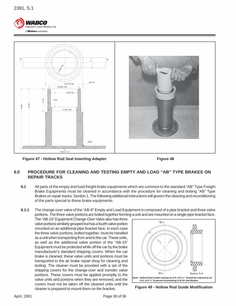
(d) Place inserting adapter, shown on Fig. 47 into cup of seal and push down until adapter stops on push rod end(See Fig. 48).
(e) Remove inserting adapter and funnel adapter.
4.3.4 Apply new packing cup to piston by starting the cup over one edge of piston and, while holding it in thisposition, work cup into place with hands. If cup does not seat properly due to trapped air, remove air by raisingone side of cup. It is recommended this be done by using wooden tool and pressing cup into place with handsworking towards wooden tool. Lubricate the side walls of the cylinder, the piston guide ring and the sealingperiphery of the packing cup with brake cylinder lubricant. DO NOT INTENTIONALLY APPLY LUBRICANT TOTHE DOME SECTION OF THE PACKING CUP OR THE PRESSURE HEAD OF THE CYLINDER.
4.3.5 Insert piston hollow rod assembly into cylinder. Start piston by tilting head of piston across cylinder openingand press piston into cylinder until packing cup clears top of cylinder, then raise piston rod until it is parallelwith bore of cylinder.
4.3.6 Position hollow rod guide gasket on hollow rod guide. Make certain gasket remains positioned properly byapplying a light film of brake cylinder lubricant to the gasket before positioning (See Fig. 39).
4.3.7 Return cylinder piston assembly to car for installation on unit body.Protect against dirt and water while handling to car.
4.4 INSTRUCTIONS FOR REPAIRING DETAILS WHEN REQUIRED
4.4.1 If push rod end is loose in piston hollow rod, proceed as follows fordisassembling WABCO magneformed and NYAB riveted pistonhollow rod assemblies:
(a) Straighten lock ring, then use spanner wrench shown on Fig. 40 toremove lock plug and lock ring from piston.
NOTE: To avoid hollow rod damage when disassembling or assemblinglock plug, piston hollow rod assembly must be restrained fromrotation at lugs on underside of piston (See Fig. 41 - Fixture on Fig.42 and 43). CAUTION - Do not place hollow rod in vise.
(b) Remove push rod end, anti-rattler ring, and hollow rod seal frompiston hollow rod (See Fig. 42).
4.4.2 For reassembling WABCO magneformed and NYAB riveted piston hollow rod assembly:
(a) Apply a light film of brake cylinder lubricant to the I.D. of anti-rattler ring to ease assembly. Place anti-rattlerring on push rod end, then insert push rod end into piston hollow rod.
Figure 39

2391, S.1
April, 1991 Page 26 of 36
(b) Position lock ring on piston. Coat threads of lock plug with sealant (Mobil jointite pipe joint compound orequivalent) and insert lock plug into piston. Use spanner wrench, shown on Fig. 40, to tighten lock plug to anequivalent of 80 to 110 ft. lbs. torque. Crimp lock ring into notch in piston and at either one of two notches inlocking plug.
4.4.3 Dimensional checks of parts in following steps need not be made if inspection indicates no wear or very littlewear. However, if inspection reveals either goughing, severe wear, thin walls, or other damage, check formaximum wear limits as specified.
(a) Piston hollow rod must be replaced if diameter is worn to 315/16” or less.
(b) Non-interlocking type hollow rod guide must be replaced if bore diameter is 45/32” or more.
(c) Interlocking type spring seat which guides hollow rod must be replaced if bore diameter is 45/32” or more.
(d) Cylinder must be replaced if bore diameter is 5/64” more than nominal.
(e) Piston Guide Ring Thickness - With guide ring assembled to piston, check that ring is not worn to pistondiameter.
Use interlocking type spring seats and hollow rod guides when replacement of either part is necessary.
NOTE: Hollow rod guides which have 61/2” shoulder stops (OD) cannot be used in 61/2”, 71/2”, or 81/2” piston assemblies,but may be used in 9” or 10” assemblies. However, they may be altered to fit all assemblies as shown in Fig. 49.
4.4.4 If push rod threads are damaged, use 11/4” - 7 UNC 2A thread die to clean up threads.
4.4.5 To replace hollow rod seal that is damaged, push damaged seal further into hollow rod using the tool shown onFig. 45 and insert diaphragm type seal as follows:
(a) Place funnel adapter, shown on Fig. 46, over end of hollow rod.
(b) Coat O.D. and I.D. of hollow rod seal with brake cylinder lubricant to facilitate assembly.
(c) With open portion of seal facing upward, stretch I.D. of seal over hex portion of push rod end. Push O.D.portion of seal down until flush with or just below top of funnel adapter.
(d) Place inserting adapter, shown on Fig. 47 into cup of seal and push down until adapter stops on push rod end(See Fig. 48).
(e) Remove inserting adapter and funnel adapter.
Proceed with brake cylinder reassembling in accordance with Section 4.3.

2391, S.1
Page 27 of 36 April, 1991
5.0 PROCEDURE FOR CLEANING and TESTING “AB-1-B” TYPE BRAKES ON REPAIR TRACKS
5.1 All parts of the “AB-1-B” Type Freight Brake Equipment which are common to the standard “AB” Type FreightBrake Equipments must be cleaned in accordance with the procedure for cleaning and testing “AB” TypeBrakes on repair tracks: Section 1. The following additional instruction will govern the cleaning and reconditioningof the parts special to these brake equipments.
5.2 The AB-1-B Type Control Valve, used with the AB-1-B Type Freight Brake equipment, is the same as thestandard “AB” Type Control Valve except for the addition of a filling piece with selector valve portion and longeremergency portion bolting studs in the standard pipe bracket to compensate for the additional thickness of thefilling piece, which is bolted on between the pipe bracket and the emergency portion.
The selector valve portion must be protected while off the car by the brake manufacturer’s standard shippingcovers. When the car brake is cleaned, the selector valve portion must be replaced by a complete cleanedportion and the one removed, transported to the air brake repair shop.
Required ActionAdd Sealant
Scrap Weld To Lock Plug
Rivet Type (NYAB) XRivet Type (WABCO) XMagneformed X XAlready Welded XMagneformed PF XMagneformed PFS X
Piston Rod Assemblies
Table 2

2391, S.1
April, 1991 Page 28 of 36
Figure 40 - Spanner Wrench for Lock Plug
Figure 41
Figure 42
11/2”7/16”3/4”
3 /4”
21 /4”
18”
0.371 ±0.001 Drill2 - Holes
3/8” x 13/16“St. DowelPin Part No.5356602 RequiredPress inPlace
Round Sharp CornersMaterial: Steel

2391, S.1
Page 29 of 36 April, 1991
Figure 43 - Piston Assembly Jig for Removingand Installing Lock Plug 81/2, 9 and 10
Figure 44 - Piston Assembly Jig for Removingand Installing Lock Plug 61/2 and 71/2
Figure 45 - Assembly Sleeve for Push Rod Keeper Figure 46 - Hollow Rod Seal Funnel Adapter
0.368 ± 0.001 Drill(2 - Places)
0.495 ± 0.001 Drill(2 - Places)
45/
32” D
ia.
2.5”
5.0”
6.0” Dia.
½ x 15/16” Dowel PinPart No. 535661 0.372 13/16”
7/16”
1 1/4”9/16”
5/8”
2.313”
4.626”
3 3/4”
1”
11 5/8”
2 7/8” Dia.3½”Dia.
1”
We
ld
1” x 1”Square
Material: Steel#3 Extra heavysteel pipemay be used.
“A” “A”
3.81
2”Dia.
5.0” Dia.
4½” Dia.
1 5/8”
7/8”
1/4”
½”
4.015” Dia.SECTION “A”- “A”
Alum. Or Steel
0.5312 Drill2 - Holes
0.76”
30° 30°
2.50 R.
2.80”7 1/8”
14”
45° Weld
5 x 1 3/4”Channel
0.56”
2391, S.1
April, 1991 Page 30 of 36
6.0 PROCEDURE FOR CLEANING AND TESTING EMPTY AND LOAD “AB” TYPE BRAKES ONREPAIR TRACKS
6.1 All parts of the empty and load freight brake equipments which are common to the standard “AB” Type FreightBrake Equipments must be cleaned in accordance with the procedure for cleaning and testing “AB” TypeBrakes on repair tracks: Section 1. The following additional instructions will govern the cleaning and reconditioningof the parts special to these brake equipments.
6.1.1 The change-over valve of the “AB-8” Empty and Load Equipment is composed of a pipe bracket and three valveportions. The three valve portions are bolted together forming a unit and are mounted on a single pipe bracket face.The “AB-10” Equipment Change-Over Valve also has threevalve portions similarly grouped but has a fourth valve portionmounted on an additional pipe bracket face. In each casethe three valve portions, bolted together, must be handledas a unit when transporting from and to the car. These units,as well as the additional valve portion of the “AB-10”Equipment must be protected while off the car by the brakemanufacturer’s standard shipping covers. When the carbrake is cleaned, these valve units and portions must betransported to the air brake repair shop for cleaning andtesting. The cleaner must be provided with a set of theshipping covers for the change-over and transfer valveportions. These covers must be applied promptly to thevalve units and portions when they are removed, and thecovers must not be taken off the cleaned units until thecleaner is prepared to mount them on the bracket.
Figure 47 - Hollow Rod Seal Inserting Adapter Figure 48
Figure 49 - Hollow Rod Guide Modification
“A” “A”2-3
/8”D
ia.
3-21/32” Dia.
2-59/64” Dia.
2-5/8” Dia.
1-5/8”
3-7/32” Dia.
5/64” R.
6-5
/8”
6-3
/8”
9”
Weld
Section “A”-”A”
1”
2-1
/8”
6.5”
Dia6.25” D
ia.
“A”
“A” Section A-A
Note: Hollow Rod Guides having an O.D. of 6 1/2” should be reduced to anO.D. of 6 1/4” to permit Assembling in B-3A Unit Bodies.

2391, S.1
Page 31 of 36 April, 1991
6.1.2 The “J” Type Change-Over Valve is composed of a change-over valve portion, a relay valve portion, and a pipebracket. While being transported to and from the car, the portions must be effectively protected against damageand contact with any kind of dirt. It will be the responsibility of individual railroads to provide such adequateprotective means.
6.1.3 EMPTY AND LOAD BRAKE CYLINDERS
Disconnect the brake cylinder lever from both push rods. Remove the complete piston, rod, spring, and non-pressure head assembly from both cylinders and transport these parts to the shop for reconditioning andtesting. The cleaner must then proceed to clean the empty and load cylinders in the same manner as specifiedfor the 10” cylinder of the standard “AB” Type Equipment. The latch box and notched rod of the load cylindershould be dismantled in the brake shop.
Remove the piston packing cup and place the assembly in a holding fixture provided with a means for clampingthe piston, so that the latch box can be unscrewed from the rod after the holding screws are removed and thenon-pressure head is depressed against the release spring. The notched rod can then be withdrawn from thehollow piston rod with the latch box. The latch box parts must be inspected and cleaned, making certain thelatch operates freely to its locked and unlocked positions. Then clean and recondition the piston and non-pressure head elements as directed for the “AB 10” cylinder.
NOTE: The Cover for “AB-1” and “AB-2” Valves is also used for AB-3-A” and “AB-4-A” Change-Over Valves.
6.1.4 The strut cylinder must be removed from its bracket on the truck bolster and transported to the air brake shopfor reconditioning. Care must be exercised to protect this device against dirt and damage with shipping cover orother means after it is removed from its bracket and while being transported to and from the shop. If anothercylinder is not to be applied immediately, the bracket ports must be protected against the entrance of dirt.When mounting, the cap screws which hold the strut cylinder on its bracket must be tightened firmly and thelock washers adjusted so that the screws cannot work loose.
Figure 50 - Shipping Cover for AB-1B Selector Valve Figure 51 - Outline View of AB-1B Selector Valve

2391, S.1
April, 1991 Page 32 of 36
6.1.5 The strut cylinder hose and connections must be inspected for chafing and other evidence of damage, or anyconditions which may lead to failures in service. This will include the hose clamps, the cap screws andclamping nuts of the flanged fittings, the pipe supporting clamps and the bolts attaching the strut cylinder to thebolster.
6.1.6 The “AB-10” Empty and Load Brake has a brake cylinder tee bolted to the brake cylinder connection on the“AB” Valve Pipe Bracket which must be removed and transported to the air brake repair shop to be dismantled,inspected and cleaned. Before reassembling, it must be known that the spring and check valve are in goodcondition, that the valve has a good bearing on its seat, and that choke fitting orifice is clean and of the propersize. This brake cylinder tee should be protected while off the car.
6.1.7 The entire brake equipment must be tested as requiredby the standard code of tests. The strut cylinderadjustment must be checked and adjusted asdirected on following pages.
6.2 Tools and equipment required for “AB” Type Emptyand Load Brake Devices are the same as those listedin the procedures for the standard “AB” Type BrakeEquipment, and in addition, a set of manufacturer’sstandard shipping covers for the valve portions thatare special to these equipments.
Figure 52 - Shipping Covers for “AB” Empty and Load Equipment
Figure 53 - Empty and Load Cylinder
For “AB-2” Check Valve CasePart No. 514824 (CV542)
For “AB-1” and “AB-2” ValvesPart No. 514820 (CV547)
For Strut CylinderPart No. 514811 (CV537)

2391, S.1
Page 33 of 36 April, 1991
6.2.1 STRUT CYLINDER ADJUSTMENT
Fig. 55 shows the “B” type strut cylinder, whichis adjusted at the test rack during shop test.
Fig. 54 shows the installation of the ABEL andA-1-B strut cylinder on the car truck bolster withthe piston at full stroke. To adjust the stroke,proceed as follows:
With the car empty and brake pipe charged,pull down the strut cylinder piston by hand untilhole “D” through the piston rod, is exposed.Place a nail, of a size to make a fairly close fit,in this 1/8” hole and let the piston move backinto the cylinder, being sure to have the nail ingroove “C” in the strut cylinder non-pressurehead.
Space “A”, between the strut piston foot andpiston stop bracket, should now be adjusted toone-half the approximate truck spring deflectionfrom empty to fully loaded. For example, on carswith 3/4” spring deflection, the space “A” shouldbe adjusted to 3/8”.
To adjust this space, remove cotter (7) and turn the piston foot (6) to the right to increase and to the left todecrease the space. A flat wrench hold is provided on the piston rod above the threaded portion to prevent thepiston rod turning when adjusting the foot.
After proper adjustment has been made, cotter (7) must be replaced and the ends spread.
A 11/8” open end wrench is required for the jam nut on the strut cylinder piston rod.
An additional hole “E” through the piston rod is provided for use in the event that smaller than nominal diameterwheels are being used for any reason and the truck is shimmed at the springs to provide proper car couplerheight.
As a further provision for adjustment when smaller thannominal diameter wheels are used, such as returned steelwheels, additional rivet holes “F” are provided in the pistonstop bracket in order that it may be located closer to thestrut cylinder piston if necessary to obtain the requiredspace.
After the space “A” has been properly adjusted, removethe nail from hole “D”, reduce brake pipe pressure to lessthan 25 pounds, then charge the equipment and applythe brake. The brake should be in empty position, indicatedby the piston of the empty brake cylinder moving out alone.
Figure 54 - ABEL & A-1-B Strut Cylinder Adjustment
Figure 55 - Type “B” Strut Cylinder
Strut CylinderB
C D
7
FE6
A
Piston StrapBracket

2391, S.1
April, 1991 Page 34 of 36
Next place a spacer 1/16” thicker than that for which space “A” has been adjusted (a nut of the correct thicknesswill serve) on the piston stop bracket so that it is between the bracket and piston rod foot (6). Again reducebrake pipe pressure to less than 25 pounds, recharge, and apply the brake. Both brake cylinder piston rodsshould move out, indicating that the equipment is in load position.
When, for any reason, the relation of the truck bolster and truck side frame is changed, as by altering theshimming up of the truck springs, the strut cylinder piston rod must be readjusted. If the car is empty, proceedas directed in preceding paragraphs.
If the car is loaded, before placing the lifting jacks under the car and with the strut cylinder piston fully retracted,measure accurately the distance between the end of the strut piston rod and its stop on the truck frame. Afterthe shimming operation is completed and the jacks removed, readjust the strut cylinder piston rod so it will beat the original measured distance from its stop. It is preferable that the proper adjustment of the strut cylinderpiston rod should be made only when the car is empty.
6.2.2 STRUT CYLINDER TEST
Charge the brake pipe and maintain the pressure between 20 and 25 pounds, then inspect the pipe and itshose connections leading from the change-over valve to the strut cylinder.
If the car is loaded and equipped with a B-2 strut cylinder or empty and equipped with either an ABEL or A-1-Bstrut cylinder, also inspect the duplicate of this pipe between the strut cylinder and change-over valve. If the caris empty and equipped with a B-2 strut cylinder or loaded and equipped with either an ABEL or A-1-B strutcylinder, there will be no air pressure in this second pipe and it can only be pressure tested as follows:
Remove the strut cylinder from its bracket, then attach special test plate, Part No. 554337 with gasket, PartNo. 515123 to the pipe bracket with 11/16” drill hole in test plate against the pipe bracket for B-2 strut cylinder andmilled slot in test plate against the pipe bracket for ABEL or A-1-B strut cylinder.
All leaks and other irregularities must be corrected.
Slowly increase the brake pipe pressure and note the value of this pressure when the strut cylinder pistonretracts. This should not be less than 25 or more than 35 pounds pressure. If the cut-off pressure is outsidethese limits, replace the cut-off valve portion with one which is known to be properly adjusted.
7.0 PROCEDURE FOR CLEANING “AB” TYPE BRAKES THAT HAVE BEEN SUBMERGED
7.1 Remove all pipes from the “AB” pipe bracket andauxiliary air device pipe brackets, reservoirs, brakecylinder, and retaining valve and remove the pipebrackets from the car.
7.2 Remove and clean the emergency and auxiliaryreservoir pipe strainers.
7.3 Loosen any foreign matter in the pipe bracketpassages, using suitable shaped scrapers, andthen blow out all passages with the highestavailable air pressure. Also wash out the passageswith high pressure water, using a small nozzlewhich will enter the ports and then dry all portsand passages thoroughly by blowing air pressurethrough them with the pipe bracket placed invarious positions.
Figure 56 - Bolting Faces - Emergency Portion &Pipe Bracket Emergency Face
e3 Q.A.C.
c3c2
b4
b4
b4
c3c2
c
Q.A.C. e3
c

2391, S.1
Page 35 of 36 April, 1991
7.4 The quick action chamber port marked “QAC”, Fig. 56 must be thoroughly blown with air pressure to insure theremoval of all water and dirt from the quick action chamber volume in the bracket.
7.5 Clean all reservoirs and volumes by washing out with high pressure water using a suitable nozzle, then allow allwater to drain until dry.
7.6 Clean the inside of all pipes by first hammering, then wash and blow them out with air pressure.
7.7 Apply the pipe brackets and reservoirs to the car, replace the auxiliary and emergency reservoir pipe strainersand, after coating the cap screw threads with grease, reconnect all pipes. All C.O.T. and S. procedures mustbe followed.
8.0 PROCEDURE FOR CLEANING AND TESTING SECONDHAND “AB” TYPE BRAKES PRIORTO REAPPLICATION TO FREIGHT CARS
8.1.1 Remove service and emergency portions from pipe bracket and clean and test these portions in accordancewith the procedure for cleaning and testing “AB” Type Brakes on repair tracks: Section 1.
8.1.2 Thoroughly clean and blow out all passages in pipe bracket and renew the strainer. Special care must be giventhe quick action chamber to insure that no moisture or dirt remains in the chamber.
Recondition threads in all threaded holes in pipe bracket, using a bottom tap of proper size for this purpose.This is to insure that cap screws will tighten firmly when attaching flanged pipe fittings.
Renew service and emergency portion gaskets.
8.1.3 Clean, inspect and lubricate brake cylinder in accordance with the procedure for reconditioning and testingbrake cylinder pistons and associated parts in the shop: Section 2 “AB” Type. Remove pressure head andrenew gasket.
8.1.4 Dismantle the double chamber reservoir, clean interior thoroughly and inspect for cracks, then spray the interiorwith suitable paint or rust preventative. Renew the reservoir gaskets when reassembling the reservoir. Afterreassembling, both compartments of the reservoir must be subjected to hydrostatic test of not less than 165pounds. Both compartments must also be drained and blown dry with air. Special care must be used to seethat separation plate is placed in proper position.
8.1.5 New gaskets and compression rings should be used when connecting pipes to flange type fittings of variousparts of the “AB” Type Equipment.
9.0 RUBBER PARTS, SHELF LIFE, AND STORAGE
9.1 New rubber parts such as gaskets, o-rings, rubber seated check valves, seals, diaphragms, etc., must not beapplied if over five years old.
9.2 The storage area for rubber parts must be cool, dark, and free from dampness and mildew. Since most rubbergoods are affected by ozone, they must not be stored near electrical equipment that may generate ozone.
9.3 To determine shelf life, new rubber repair kits must be dated with the oldest date (half year) of rubber componentscontained within the kit.

2391, S.1
April, 1991 Page 36 of 36
WABCO Freight Car Products1001 Air Brake Avenue www.wabtec.com 475 Seaman StreetWilmerding, Pennsylvania 15148 Stoney Creek, Ontario L8E 2R2(412) 825-1000 • Fax (412) 825-1019 (905) 561-8700 • Fax (905) 561-8705