
Reinforcement to the North Shropshire Electricity ... · The current local electricity distribution...
26
Reinforcement to the North Shropshire Electricity Distribution System Updated Strategic Options Report November 2017
Transcript of Reinforcement to the North Shropshire Electricity ... · The current local electricity distribution...

Reinforcement to the North Shropshire
Electricity Distribution System
Updated Strategic Options Report
November 2017
Page 1 of 26
Contents
1 Introduction ..................................................................................................... 2
2 The Need for the Reinforcement of the 132kV Network .................................. 3
2.1 North Shropshire Growth Plans ............................................................................... 3
2.2 Background Demand Growth, Including Low Carbon Technologies (LCTs) ............ 3
2.3 Obligations .............................................................................................................. 4
2.4 Reinforcement Requirement .................................................................................... 5
2.5 Consequences of Not Reinforcing the Network ....................................................... 5
3 The Existing 132kV and 33kV Networks in North Shropshire ......................... 6
3.1 Interface with National Grid ..................................................................................... 6
3.2 The Existing Network .............................................................................................. 6
4 Design Requirements ..................................................................................... 9
4.1 Thermal Conditions ................................................................................................. 9
4.2 Fault Level .............................................................................................................. 9
4.3 Voltage Levels ......................................................................................................... 9
4.4 Security of Supply ................................................................................................. 10
4.5 Losses ................................................................................................................... 10
4.6 Environmental Impact ............................................................................................ 10
4.7 National Policy Statements .................................................................................... 10
5 Strategic Options for the Reinforcement ....................................................... 11
5.1 SP Manweb Network Design ................................................................................. 11
5.2 Existing and Proposed Network with Diagram Key ................................................ 12
5.3 Proposed Option (132kV Circuit Oswestry-Wem and 132/33kV Transformer) ....... 13
5.4 132kV Circuit Design ............................................................................................. 14
5.5 Do Nothing ............................................................................................................ 18
5.6 New Technology Solutions .................................................................................... 18
5.7 Increasing the 33kV Connectivity Within the Group ............................................... 19
5.8 Increasing 33kV Connectivity Coupled With New Technology ............................... 20
5.9 Voltage Up-ration of an Existing Circuit from 33kV to 132kV ................................. 20
5.10 Establish New 132/33kV Supply at Whitchurch ..................................................... 21
5.11 Establish New 132/33kV Supply at Wem ............................................................... 21
5.12 Establish a New Supply Directly From NGET Network .......................................... 23
6 Conclusions .................................................................................................. 24
Appendix 1 – North Shropshire Environmental Constraints ...................................... 25

Page 2 of 26
1 Introduction
SP Manweb Plc (“SP Manweb”) is planning to invest £18m in order to support and enable
growth across North Shropshire. This investment is to reinforce the electricity distribution
network by constructing an overhead wood pole 132kV line from Oswestry substation,
located at the A5/A495 roundabout, and Wem substation, located on Ellesmere Road on the
western side of Wem.
This line will provide capacity to support development on land allocated for new jobs and
homes in Oswestry, Whitchurch and Wem in current planning forecasts to 2026 and attract
future business and housing investment across North Shropshire through to and beyond
2040. The new 132kV overhead line will provide support to the existing 33kV and 11kV
electricity distribution networks by increasing the capacity available throughout the North
Shropshire area.
SP Manweb has investigated a number of options for reinforcing the network and proposes
that a new 132kV wood pole line and 132/33kV transformer in-feed is the most appropriate
solution. This report is an updated version of the document that was previously published in
May 2016, and details the options considered and the reasons for the preferred design. The
options considered in 2016 have been reviewed in light of predicted changes in demand, and
the preferred option is unchanged compared with the conclusions of the 2016 report.
SP Manweb is the licenced electricity Distribution Network Operator (DNO) which owns and
manages the electricity distribution network within Cheshire, Merseyside, North Shropshire
and North Wales. The network is used to distribute electricity, which has been transmitted to
grid supply points, for electricity supply companies to sell onto their customers. SP Manweb’s
role is to develop and maintain an efficient, co-ordinated and economical system of electricity
supply in the area for which it is responsible. As such, it is the named applicant for this
proposed development.
SP Manweb is part of SP Energy Networks which owns three regulated electricity network
businesses in the UK. These are SP Manweb, SP Distribution and SP Transmission. SP
Distribution and SP Transmission transmit and distribute electricity in Central and Southern
Scotland. SP Energy Networks supplies electricity to:
• 1.5 million customers in Merseyside, Cheshire, North Wales
and North Shropshire*
• 2 million customers in Central and Southern Scotland

Page 3 of 26
2 The Need for the Reinforcement of the 132kV Network
2.1 Updated North Shropshire Growth Plans
SP Manweb has been in discussion with Shropshire Council for many years. In preparing its
business plans for the current regulatory period (RIIO-ED1), this area of network was
identified and recognised as requiring reinforcement. This major reinforcement scheme will
facilitate and attract business and housing investment across North Shropshire. SP Manweb
has been working closely with Shropshire Council to understand the level of expected
development and the land allocated for new jobs and homes, particularly in and around
Oswestry, Whitchurch, Wem and Ellesmere.
Shropshire Council’s SAMDev (Site Allocations and Management of Development) Plan,
which was published in 2015, identified growth strategies in a number of towns and villages
in the north of the County through to 20261, and showed areas of land for both housing and
employment uses. Whilst some of this development had already been built in the early part
of the Plan, there still remained approximately 4,120 dwellings and 63 hectares of
employment land to be delivered up to 2026. Looking beyond 2026, the council is currently
consulting on a new growth strategy for the period 2026-20362 for which the planned growth
in housing is 11% higher than for the previous strategy, with approximately 4,558 dwellings
to be delivered by 2036. In addition, the connected load in this area has increased since the
Strategic Options Report was first published in May 2016.
Much of the development demand is expected to materialise in and around Whitchurch and
Oswestry, and also on the long 33kV interconnections between Whitchurch and Oswestry.
SP Manweb continues to work closely with its stakeholders, including Shropshire Council
and developers connecting directly to its networks.
2.2 Background Demand Growth, Including Low Carbon Technologies (LCTs)
SP Manweb has to accommodate the peak demands that customers require from its
networks. These peak demands often occur for a short period and are not well correlated
with customers’ overall energy consumption. During the economic downturn the number of
units (kWh) distributed were observed to be falling in some years but the peak demands on
the network did not change in the same way. During the current regulatory period (RIIO-
ED1) SP Manweb expects to see modest demand growth throughout the period. It is
anticipated that the main driver of demand growth, particularly during the latter half of the
RIIO-ED1 period, will be customer uptake of Low-carbon Technologies (LCT). The LCT
analysis in the SP Manweb’s RIIO-ED1 business plan is based upon scenarios developed by
the Department of Energy & Climate Change (DECC, now BEIS). Each DECC Scenario was
designed to achieve the Fourth Carbon Budget, and SP Manweb used the models developed
by the industry to assess the impact on their networks. SP Manweb’s “best view” of LCT
uptake is regularly held under review and informed by a range of industry sources including
the annually published National Grid Future Energy Scenarios (currently under review).
1 Shropshire Council Site Allocations and Management of Development (SAMDev) Plan, Adopted Plan, 17/12/2015
2 Shropshire Local Plan Review, Consultation on Preferred Scale and Distribution Development, Consultation Period:
27th
October 2017 – 22nd
December 2017

Page 4 of 26
2.3 Obligations
SP Manweb has a responsibility to ensure that the electricity distribution network for the
North Shropshire area is constructed, operated, and maintained in a technically efficient and
cost-effective manner and has minimal impact on the environment.
The current local electricity distribution network has been supplying North Shropshire reliably
for many years. But with future growth plans in the region planned up to 2036, there is a
need to reinforce the network. This is to provide additional capacity to support development
and growth.
In acting on behalf of the holder of an Electricity Distribution Licence for the Cheshire,
Merseyside, Shropshire, North and Mid Wales area, SP Manweb must comply with various
statutory and licence duties and obligations. Such duties require us to develop, maintain and
continue to provide an efficient, co-ordinated and economical system of electricity
distribution. Conditions of the Distribution Licence are such that SP Manweb has a
responsibility placed upon it to plan and develop the distribution system in accordance with a
standard not less than that set out in Engineering Recommendation P2/6 (ER P2/6).
ER P2/6 is considered to be the minimum level of security standard which sets out the
expected levels of security required for distribution networks and is classified in ranges of
Group Demand. This document has been adopted by the distribution network operators
(DNOs) to ensure commonality across distribution networks with regards to network security
of supply.
In terms of the relevant legislation, Section 9(2) of the Electricity Act 1989 requires SP
Manweb:
(a) “to develop and maintain an efficient, co-ordinated and economical system of
electricity transmission; and
(b) to facilitate competition in the supply and generation of electricity.”
Section 38 and Schedule 9 of the Electricity Act 1989 requires that SP Manweb, when
formulating proposals for new lines and other works:
(a) “shall have regard to the desirability of preserving natural beauty, of conserving
flora, fauna, and geological or physiographical features of special interest and of
protecting sites, buildings and objects of architectural, historic or archaeological
interest; and
(b) shall do what he reasonably can to mitigate any effect which the proposals would
have on the natural beauty of the countryside or on any such flora, fauna, features,
sites, buildings or objects”.

Page 5 of 26
2.4 Reinforcement Requirement
Reinforcement of the distribution network in North Shropshire is necessary in order to
establish the required level of network security for the Legacy - Newtown - Oswestry -
Welshpool - Whitchurch 33kV demand group.
The 33kV network in the Whitchurch/Wem area is presently operating near thermal and
voltage limits for a 132kV circuit or 132/33kV transformer outage at Whitchurch during winter
maximum demand conditions. The 33kV group is therefore supplying close to its maximum
capacity. The capacity of this 33kV group is limited as a result of the overall natural network
topology. The network is comprised of a limited number of 132/33kV transformer in-feeds
into this area of 33kV network. The 33kV circuits which interconnect these transformer in-
feeds are therefore long, and also of limited number. Under conditions where the 132/33kV
transformer in-feed at Whitchurch is unavailable, the 33kV network must still be supplied.
Under these conditions, the power is distributed through long distances of 33kV circuits to
supply the demands in the Whitchurch and Wem areas of network. The magnitude of current
flow through these 33kV circuits are such that some circuits are at risk of exceeding thermal
ratings and the voltage drop along these circuits is already close to statutory limits. It is
becoming problematic to accommodate additional demand in this area and this network
would be unable to accommodate the level of demand growth indicated by Shropshire
Council.
To accommodate sustained demand growth in the area, network reinforcement is required.
When preparing both fast-track and slow-track RIIO-ED1 business plans (from 2013), SP
Manweb included plans for a major reinforcement of the 132kV network in this area.
2.5 Consequences of Not Reinforcing the Network
Failure to reinforce the group would impede or prevent economic growth in the area. Failure
to reinforce the group could also risk thermal overloads and voltage issues as demand is
expected to continue to increase for the group. This would pose a risk to the security of
supply to thousands of the 62,250 customers supplied by this group. The loss of supply to
such a number of customers would be dramatic, with the range of sensitivities to a supply
interruption, from such a large range of customer types, having a wide spectrum of impacts:
Domestic customer loss of lighting and heating;
Loss of public street lighting, traffic lights, gas & water supplies and water treatment
works processes;
Telecommunications systems limited;
Large disruption for offices, factories, shops and workplaces;
Hospitals not able to function effectively (limited on-site backup generation);
Schools, GP surgeries, nursing homes and emergency services severely impacted
Priority treatments for dialysis (local portable generators).
Furthermore, failure to reinforce the network would lead to a non-compliance of ER P2/6 and
breach of Condition 24 of the distribution licence, which can ultimately result in financial
penalties.
The various options available to help increase the security of supply for the North Shropshire
area have been considered, and out of all the options considered the proposed solution of a
new 132kV single circuit wood pole line from Oswestry to Wem and associated 132/33kV
Page 6 of 26
transformer in Wem substation is considered as the most appropriate option to address the
network issues.
3 The Existing 132kV and 33kV Networks in North Shropshire
3.1 Interface with National Grid
Electricity is primarily generated at large power stations and supplied to customers through
an integrated high voltage transmission system operated in England and Wales by National
Grid Electricity Transmission plc (NGET). The national high voltage transmission system
operates at 400kV and 275kV.
Lower voltage distribution systems are operated by Distribution Network Operators (DNOs).
As a DNO, SP Manweb takes supplies from NGET at Grid Supply Points (GSPs). These
supplies are converted from 400/275kV to lower voltages and SP Manweb then distributes
electricity around its area at 132kV, 33kV and at lower voltages to customers’ premises. The
distribution system consists primarily of overhead lines, cables, transformers and
substations.
3.2 The Existing Network
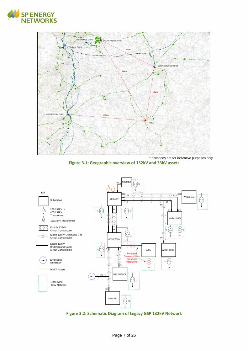
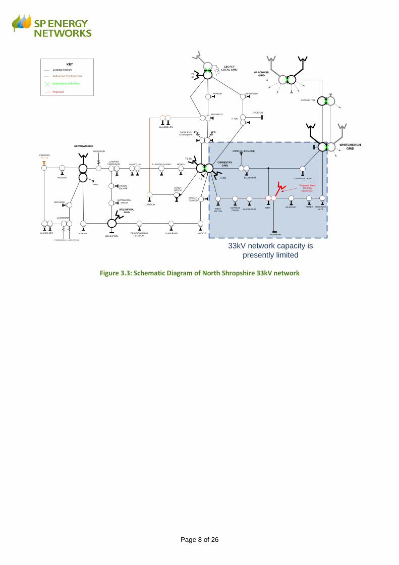
The relevant parts of the SP Manweb distribution network are shown geographically in Figure
3.1 and schematically in Figure 3.2 (132kV) and Figure 3.3 (33kV). Reference to these will
aid understanding of the written information in this report.
The capacity of the 33kV network in the Whitchurch/Wem area is limited as discussed in
Section 2.
Electricity is supplied to this area of network from the National Grid interface at Legacy GSP,
then through 132kV network to 132/33kV transformers at Bulk Supply Points (BSPs) located
in substations located at Legacy, Newtown, Oswestry, Welshpool and Whitchurch. The
design of the SP Manweb network means that BSPs are interconnected through the 33kV
network and these substations are operated as a group. The 33kV network operates fully
interconnected within the network group, and is coupled to adjacent 33kV network groups at
Marchwiel via long overhead lines and at Legacy through a 33kV reactor located in Legacy
substation. SP Manweb is the only UK DNO to run a fully interconnected distribution
network, with key benefits being a more ‘resilient’ network to system outages and
interruptions.
Page 7 of 26
* distances are for indicative purposes only
Figure 3.1: Geographic overview of 132kV and 33kV assets
Figure 3.2: Schematic Diagram of Legacy GSP 132kV Network
LEGACY GRID
WHITCHURCH GRID
OSWESTRY GRID
WEM
WREXHAM GRIDMARCHWIEL GRID
16km
28km
13km
22km
LEGACY
WELSHPOOL
NEWTOWN
WREXHAM
MARCHWIEL
WHICHURCH
T2 T1
T1
T2
T1 T2
T1
T1
T2
BJ
BK
EJ
EJ
BU
BU
275/132kV or
400/132kV
Transformer
KEY
Double 132kV
Circuit Construction
Substation
132/33kV Transformer
Embedded Generator
Single 132kV Overhead LineCircuit Construction
NGET Assets
Single 132kV
Underground Cable Circuit Construction
~
~Underlying
33kV Network
T1
BRYMBOT1
BK
EX
BH
EX
EXCT
CT
BH
DF
MB
Proposed
Oswestry-Wem
circuit and
Transformer
WEM
OSWESTRY
Page 8 of 26
Figure 3.3: Schematic Diagram of North Shropshire 33kV network
T1
LECACY
LOCAL GRID
NEWTOWN GRID
OSWESTRY
GRID
WELSHPOOL
GRID
JOHNSTOWN
OVERTONMONSANTO
RUABON
CADBURYS/
KRONOSPAN
ELLESMERE
IFTON
MMB ELLESMERE
LLANDDU QUARRY MORDALLANFYLLIN
TREGYNON
LLANFAIR
CAEREINION
MILFORD
CAERSWS
+5 / -15
FORDEN
MOCHDRE
CRIGGION RADIO
STATIONLLANDRINIO LLYNCLYS
LLANSILIN
CONEY
GREEN
MAES-Y-
CLAWDD
PENRHUDDLAN LLIDIARTWAUN
WEST
FELTON
EXPRESS
FOODSBASCHURCH
WEM
SHAWBURY
WEM EAST PREES YOCKINGS
GATE
LIVERPOOL ROAD
WHITCHURCH
GRID
T2
45
T1 45
T2 60
LLANIDLOES
RAVEN
SQUARE
BUTTINGTON
CROSS
BRD
WELSHPOOL
LLANGOLLEN
LLANDINAM
Existing Network
KEY
Authorised Reinforcement
Opperational Split Point
Proposed
33kV network capacity is
presently limited
MARCHWIEL
GRID
DUCKINGTON
Proposed Wem
132/33kV
transformer

Page 9 of 26
4 Design Requirements
There are various issues relating to the existing distribution system, regardless of cable or
overhead line, which are considered when reviewing the need for system reinforcement,
these include:
Thermal Conditions: assets must normally operate within their rating;
Fault Levels: assets must operate within their rating;
Voltage Levels: system voltages must be kept within statutory limits;
Security of Supply: the network must operate within the security standards;
Losses: network losses should be minimised as far as is practicable;
Environmental Impact: limit effects on the natural beauty of the countryside;
National Policy Statements: sets out the Government's policy for delivery of
major energy infrastructure
4.1 Thermal Conditions
Overhead line conductors are designed for a certain operating temperature, and safe
clearances between the conductors and the ground/structures are based on this assumption.
The thermal rating translates into standard seasonal current ratings. Overloading causes
conductors to overheat which will increase the sag of the conductors and reduce safety
clearances. Operating at a temperature greater than their design temperature could also
lead to a reduction in conductor strength.
4.2 Fault Level
The SP Manweb 132kV design fault level limit is 20kA (4,570MVA) for three phase faults and
25kA (5,700MVA) for single phase faults. A high fault level improves the quality of supply by
reducing the magnitude of short-term voltage fluctuations, but the fault level must also be
kept within the short-circuit capability of the plant and switchgear, otherwise catastrophic
equipment failure can result during a network fault. Therefore, the design approach is
generally to keep the fault levels as high as possible, whilst also maintaining sufficient design
margins relative to the plant rating.
4.3 Voltage Levels
The statutory voltage level limits are ±10% at 132kV and ±6% at 33kV. This allows for a
voltage gradient along the length of a circuit. The voltage gradient is directly related to the
current flowing in the conductor and it is primarily this voltage gradient that limits the practical
length of a circuit. In fact, on a power network, particularly at the higher voltages levels,
voltage drop is caused by reactive power (MVAr) flow to a much greater degree than active
power (MW) flow.
If there is an instantaneous change in power flow (for example as a result of a circuit or
transformer being switched out) this will cause an instantaneous step change in voltage.
Plant and equipment can be sensitive to sudden changes in voltage. Therefore, events that
cause instantaneous changes in power flow are avoided as much as possibleand voltage
step change is considered as part of the design process.
Page 10 of 26
4.4 Security of Supply
Distribution networks in the UK are generally designed according to the security standard
defined within the ENA Engineering Recommendation P2/6 ‘Security of Supply’. The basic
principle of P2/6 is based on the need to provide greater levels of supply security as the size
of the group load increases. Network security is created by a combination of plant
redundancy and load transfer capability. In other words, for large load groups, it should be
possible to maintain supplies to customers following an outage of any single item of plant or
to restore supplies by transferring the load into another load group by network switching.
License condition 24 places a responsibility on SP Manweb to plan and develop the
distribution system in accordance with a standard not less than that set out in Engineering
Recommendation P2/6.
4.5 Losses
Electricity distribution networks convey energy from the transmission system (or generators)
through to the low-voltage supplies used by network customers. A proportion of this energy
is lost to heat and noise as part of the supply process. As distance and the amount of
energy increase it becomes more efficient to use higher voltage circuits. For example, for a
given power transfer, if the voltage is increased by a factor of four (say, from 33kV to 132kV),
the current is reduced by a factor of four and the I2R losses are reduced by a factor of sixteen
for the same conductor size and power transfer. It is for these fundamental reasons that the
transmission of large amounts of power is achieved with higher voltage infrastructure.
License condition 49 requires SP Manweb to ensure that distribution losses are as low as
reasonably practical.
4.6 Environmental Impact
Under Section 38 and Schedule 9 of the Electricity Act 1989 SP Manweb is required to have
due regard of, and to reasonably mitigate, any effect which their proposals would have on the
natural beauty of the countryside.
4.7 National Policy Statements
The project is a nationally significant infrastructure project for the purposes of the Planning
Act 2008 and therefore a development consent order (DCO) is required. Section 104(3) of
the Planning Act 2008 states that the decision maker must decide an application for a DCO
in accordance with any relevant National Policy Statement, except in certain circumstances.
These circumstances include where the adverse impact of the proposed development would
outweigh its benefits.
Six National Policy Statements (NPSs) for energy infrastructure were published by the
Secretary of State for Energy and Climate Change in July 2011. The most relevant NPSs for
electricity infrastructure are the Overarching National Policy Statement for Energy (EN-1) and
the National Policy Statement for Electricity Networks Infrastructure (EN-5), which must be
read in conjunction with EN-1. The NPSs may also be a material consideration for decisions
on other types of development consent in England and Wales (including offshore projects).

Page 11 of 26
5 Strategic Options for the Reinforcement
This section explains the strategic options that are available which can help to increase the
capacity of a network. The ability of these options to provide the required level of capacity is
discussed. The option which meets the needs of the current and future network, whilst
ensuring an efficient, co-ordinated and economical system of electricity distribution, is
identified and explained.
5.1 SP Manweb Network Design
The SP Manweb distribution network is an interconnected network. SP Manweb is the only
UK DNO to run a fully interconnected distribution network, with key benefits being a more
‘resilient’ network to system outages and interruptions. Most distribution networks are
organised 'radially', however SP Manweb (and its predecessors) over the past sixty years
have designed and operate the distribution network as meshed at all voltage levels.
The following compares the design of a typical (generic) 33kV SP Manweb network with a
typical 33kV radial network:
Typical SP Manweb 33kV network Typical 33kV Radial network
SP Manweb designed as meshed network
Single cable section and transformer outage under fault conditions with no customer interruptions.
Highly utilised network with standardised components.
Greater volumes of switchgear/ protection, transformers and buildings.
Requires ‘unit’ protection more complex and costly.
Traditional network design based on duplicate transformer feeders operated in parallel.
Networks tend to radiate outwards from bulk supply points.
Conductors may be tapered.
In all cases the circuits are run with a split (normal open) point at an electrically convenient point.
Page 12 of 26
5.2 Existing and Proposed Network with Diagram Key
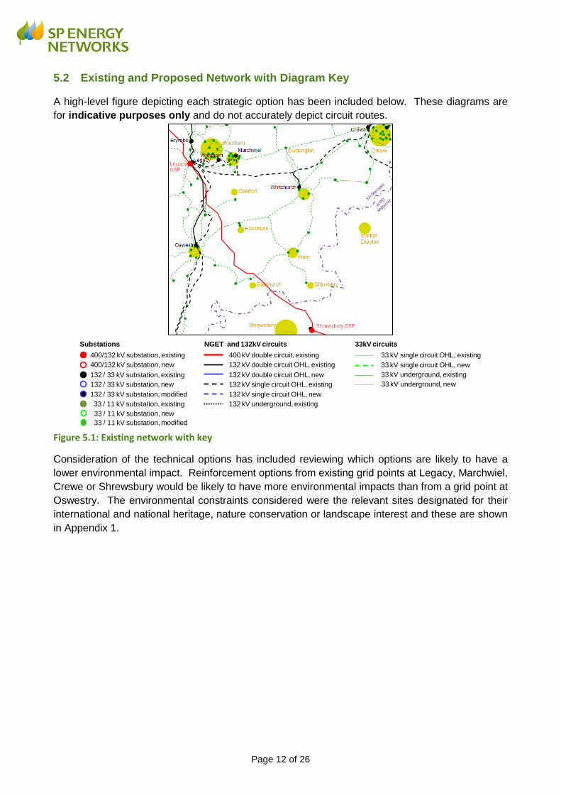
A high-level figure depicting each strategic option has been included below. These diagrams are
for indicative purposes only and do not accurately depict circuit routes.
Figure 5.1: Existing network with key
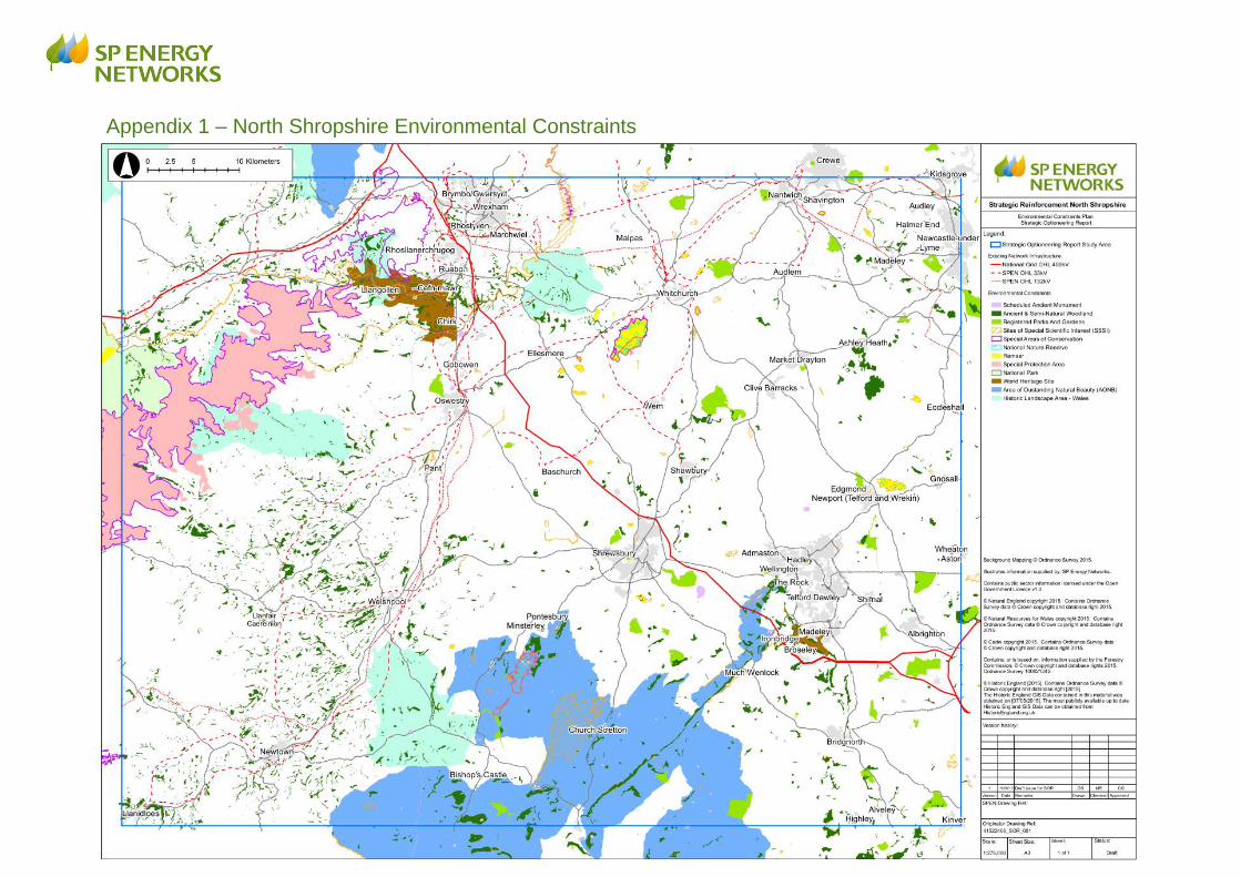
Consideration of the technical options has included reviewing which options are likely to have a
lower environmental impact. Reinforcement options from existing grid points at Legacy, Marchwiel,
Crewe or Shrewsbury would be likely to have more environmental impacts than from a grid point at
Oswestry. The environmental constraints considered were the relevant sites designated for their
international and national heritage, nature conservation or landscape interest and these are shown
in Appendix 1.
400/132 kV substation, existing
400/132 kV substation, new
132 / 33 kV substation, existing
132 / 33 kV substation, new
132 / 33 kV substation, modified
33 / 11 kV substation, existing
33 / 11 kV substation, new
33 / 11 kV substation, modified
400 kV double circuit, existing
132 kV double circuit OHL, existing
132 kV double circuit OHL, new
132 kV single circuit OHL, existing
132 kV single circuit OHL, new
132 kV underground, existing
33 kV single circuit OHL, existing
33 kV single circuit OHL, new
33 kV underground, existing
33 kV underground, new
Substations NGET and 132kV circuits 33kV circuits

Page 13 of 26
5.3 Proposed Option (132kV Circuit Oswestry-Wem and 132/33kV
Transformer)
Option New 132kV circuit Oswestry – Wem New 132/33kV transformer in Wem
Evaluation Proposed Preferred solution
The new c.22km overhead line will reinforce the existing 33kV distribution network by increasing the capacity available throughout North Shropshire.
This option is to establish a new transformer in-feed at Wem. This minimises the electrical infrastructure required and therefore associated potential environmental effects. Although, there is still a need to avoid impacts on key national designations and minimise overall impact.

Page 14 of 26
5.4 132kV Circuit Design
There are a range of different technologies available for constructing a 132kV circuit mainly
consisting of overhead line, underground cable, or a combination of both. The underground
cable is insulated and buried below ground whilst the uninsulated overhead line is
constructed above ground. The metallic overhead line is supported by insulators which are
fixed to either steel lattice structures (pylons) and / or lower profile wood pole structures.
Entirely underground
SP Manweb considers the justification for underground cable on a case by case basis. These
considerations include lifetime costs (based on capital cost, cost of electrical transmission
losses and operational and maintenance costs calculated over the asset lifetime) in addition
to the system design requirements, and the specific factors involved in each particular
proposal, such as areas of high technical or environmental constraints and areas of the
highest recognised amenity value. In this case, a high level full life cost assessment has
been made in order to understand the likely cost differential between the minimum scheme
(i.e. primarily overhead line construction) and an underground cable option.
A detailed full life cycle cost-benefit analysis for a similar 132kV new-build circuit through a
rural landscape has been modified to take into account the specific characteristics of the
North Shropshire scheme.
The North Shropshire minimum scheme comprises a 1.2km 132kV underground cable and a
132kV Trident wood pole overhead line of just over 21km in length, running between the
Oswestry and Wem substations. The total length of the overhead line and underground
cable is therefore just over 22km.
For the alternative underground cable option, a route length of 26.7km in total was found to
be required for a practical cable route. The cable route is shown below:
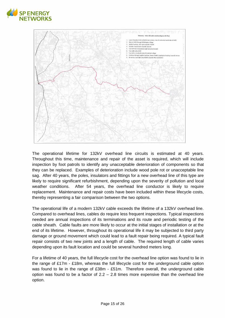
Page 15 of 26
The operational lifetime for 132kV overhead line circuits is estimated at 40 years.
Throughout this time, maintenance and repair of the asset is required, which will include
inspection by foot patrols to identify any unacceptable deterioration of components so that
they can be replaced. Examples of deterioration include wood pole rot or unacceptable line
sag. After 40 years, the poles, insulators and fittings for a new overhead line of this type are
likely to require significant refurbishment, depending upon the severity of pollution and local
weather conditions. After 54 years, the overhead line conductor is likely to require
replacement. Maintenance and repair costs have been included within these lifecycle costs,
thereby representing a fair comparison between the two options.
The operational life of a modern 132kV cable exceeds the lifetime of a 132kV overhead line.
Compared to overhead lines, cables do require less frequent inspections. Typical inspections
needed are annual inspections of its terminations and its route and periodic testing of the
cable sheath. Cable faults are more likely to occur at the initial stages of installation or at the
end of its lifetime. However, throughout its operational life it may be subjected to third party
damage or ground movement which could lead to a fault repair being required. A typical fault
repair consists of two new joints and a length of cable. The required length of cable varies
depending upon its fault location and could be several hundred meters long.
For a lifetime of 40 years, the full lifecycle cost for the overhead line option was found to lie in
the range of £17m - £18m, whereas the full lifecycle cost for the underground cable option
was found to lie in the range of £38m - £51m. Therefore overall, the underground cable
option was found to be a factor of 2.2 – 2.8 times more expensive than the overhead line
option.

Page 16 of 26
It should be noted that these ratios represent a comparison for the minimum scheme option
(1.2km 132kV underground cable and a 22.0km 132kV Trident wood pole overhead line)
versus the underground cable option (26.7km), and do not take into account the remote end
works as the design and hence cost of these works would be the same for either option.
SP Manweb does not consider the increased cost for the underground cable option to be
justified for this project, as there is an acceptable overhead line route design available.
Decommissioning
Decommissioning costs have not been included for either option, because the reinforcement
will become an integral part of the distribution network supporting load from houses and
businesses in North Shropshire, and it is therefore highly unlikely that the overhead line
would ever be decommissioned.
Regarding the cable component of the minimum scheme or the cable underground option,
should it be decided that there is no future requirement for the cable then it will be
decommissioned. However, cables are generally left in situ rather than removed.
Wood pole Trident design
Following a review of the available options for this project, SP Manweb is proposing to use a
wood pole Trident design which would comprise mostly single poles. It is considered that
this design will have least visual impact on the area compared to steel lattice construction
and provide a better fit within the local landscape. This design is a modern, low impact tried
and tested solution. It offers more flexibility in routing the line than the other options, which
helps in reducing potential impacts on important sites, communities and properties. A
Trident design also assists in addressing landowner requests when determining the best
location for poles.
Trident wood poles are approximately 12m high with poles typically spaced approximately
120m apart. Each pole carries 3 phase conductors. In comparison with a typical 33kV wood
pole circuit, the cross-arm of the 132kV Trident design is approximately 1-2m higher. The
insulator stack at 132kV needs to be larger than at 33kV to ensure electrical clearances are
maintained.
(actual heights can vary depending on design requirements)

Page 17 of 26
Construction requirements
The design includes a construction and operations corridor, proposed temporary access
points and proposed temporary laydown areas. These details are published separately in
the Works Plans for the reinforcement3. Construction access would be via local roads, farm
tracks and field gates. Construction vehicles range from 4x4 vehicles to tracked diggers.
Delivery vehicles taking materials to dedicated lay down areas would typically be up to 20
tonne lorries. The installation would have an overall construction phase of approximately 12
months.
3 Reinforcement to The North Shropshire Electricity Distribution Network: 132kV Electrical Circuit from Oswestry to
Wem, Works Plans, November 2017.

Page 18 of 26
5.5 Do Nothing
Failure to reinforce the group would risk thermal overloads and voltage issues as demand is
expected to continue to increase for the group. Furthermore, failure to reinforce the network
would lead to a non-compliance of ER P2/6 and breach of Condition 24 of the distribution
licence.
5.6 New Technology Solutions
SP Manweb has given consideration to solutions which could address the project drivers but
that employ novel, innovative or technological solutions. A range of new technology
solutions have been assessed in the context of the project drivers and have been discounted
on the basis of acceptability, applicability or economics.
Automated load transfer schemes are considered to be an option that would provide a
limited level of load growth in the short term. An automatic load transfer scheme was
considered at the Whitchurch boundary and it was found that such a scheme might be able
to accommodate some additional level of demand. However, it was also found that there
was limited thermal and voltage capacity on both sides and hence the additional demand that
could be accommodated would be limited, and that the scheme would only provide benefit to
demand connected close to this boundary. In reality, the increased demand is expected to
be distributed over a wider area. Assessments therefore indicated that this solution would
not negate or allow the conventional solution to be deferred.
Dynamic thermal rating of existing 33kV overhead lines is only able to facilitate very limited
demand growth. It would be unable to mitigate voltage issues. For example, SP Manweb’s
Flexible Networks for a Low Carbon Future project found that utilising dynamic thermal asset
ratings would provide an increase in headroom of less than 10%4, which would be insufficient
to accommodate the increased demand required for North Shropshire.
The active control of demand customers by Demand Side Management (DSM) has been
discounted. Due to the interconnected design of this area of network, the level of response
required is very sensitive to the location within the group. For this to be successful it would
be dependent on key demand stakeholders in this area and there is a significant risk that the
level of demand reduction required, near key locations within the group, cannot be met.
Furthermore, it is likely that a complex control and management scheme would be required
in order to manage and balance the available levels of DSM required since this would need
to vary and respond/react to both the time of day and network location requiring DSM.
Energy Storage Schemes (ESS) have been considered and discounted. At present there
are no installations, including trials, at the level of capacity required. This option is also
discounted on an economic basis. A battery storage solution has been investigated on
another part of the SP Manweb network to understand whether the solution could be a viable
alternative to traditional reinforcement. However, the optimal battery solution was unable to
maintain the system voltages within statutory limits, and was therefore ruled out on technical
grounds.
4 SP Energy Networks Flexible Networks for a Low Carbon Future, Work Package 2.1: Dynamic thermal rating of
assets, Dec 2014
Page 19 of 26
SP Manweb has considered more actively controlling the network by installing a 33kV
power flow controller at Whitchurch. The 'Cheshire' and 'Wales' supply areas are segregated
at Whitchurch. These areas cannot be interconnected as they are supplied by different parts
of the NGET network and interconnection would lead to power-flows which are difficult to
manage and could deplete capacity. Consideration was given to installing a 33kV Phase
Shifting Transformer (PST) in the Whitchurch substation to manage the power flows across
this boundary. The use of PSTs is not a typical business as usual solution for SP Manweb,
although a 132kV scheme involving a PST is being planned. SP Manweb does not currently
have any PSTs on the distribution network. Using a power flow controller would utilise
capacity from the adjacent group and from the adjacent upstream group (Crewe 132kV).
The adjacent upstream group is already scheduled to be reinforced using a PST. The
potential for operational interactivity between the two phase shifting transformers is unknown.
This option has not been taken forward because of the technical/operational risks outlined
above, and because of the limited capacity it releases.
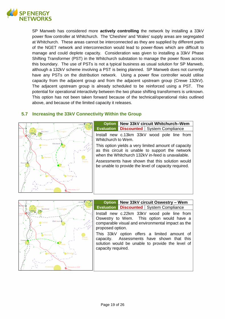
5.7 Increasing the 33kV Connectivity Within the Group
Option New 33kV circuit Whitchurch–Wem Evaluation Discounted System Compliance
Install new c.13km 33kV wood pole line from Whitchurch to Wem.
This option yields a very limited amount of capacity as this circuit is unable to support the network when the Whitchurch 132kV in-feed is unavailable.
Assessments have shown that this solution would be unable to provide the level of capacity required.
Option New 33kV circuit Oswestry – Wem Evaluation Discounted System Compliance
Install new c.22km 33kV wood pole line from Oswestry to Wem. This option would have a comparable visual and environmental impact as the proposed option.
This 33kV option offers a limited amount of capacity. Assessments have shown that this solution would be unable to provide the level of capacity required.
Page 20 of 26
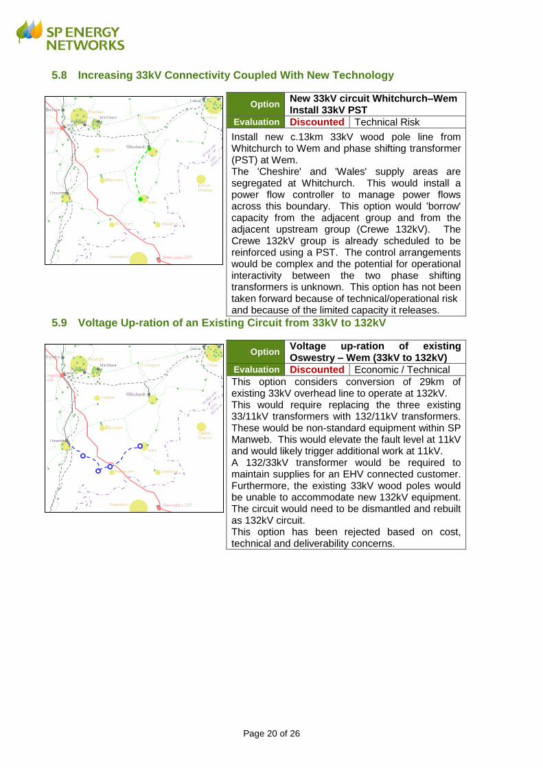
5.8 Increasing 33kV Connectivity Coupled With New Technology
Option New 33kV circuit Whitchurch–Wem Install 33kV PST
Evaluation Discounted Technical Risk
Install new c.13km 33kV wood pole line from Whitchurch to Wem and phase shifting transformer (PST) at Wem. The 'Cheshire' and 'Wales' supply areas are segregated at Whitchurch. This would install a power flow controller to manage power flows across this boundary. This option would 'borrow' capacity from the adjacent group and from the adjacent upstream group (Crewe 132kV). The Crewe 132kV group is already scheduled to be reinforced using a PST. The control arrangements would be complex and the potential for operational interactivity between the two phase shifting transformers is unknown. This option has not been taken forward because of technical/operational risk and because of the limited capacity it releases.
5.9 Voltage Up-ration of an Existing Circuit from 33kV to 132kV
Option Voltage up-ration of existing Oswestry – Wem (33kV to 132kV)
Evaluation Discounted Economic / Technical
This option considers conversion of 29km of existing 33kV overhead line to operate at 132kV. This would require replacing the three existing 33/11kV transformers with 132/11kV transformers. These would be non-standard equipment within SP Manweb. This would elevate the fault level at 11kV and would likely trigger additional work at 11kV. A 132/33kV transformer would be required to maintain supplies for an EHV connected customer. Furthermore, the existing 33kV wood poles would be unable to accommodate new 132kV equipment. The circuit would need to be dismantled and rebuilt as 132kV circuit. This option has been rejected based on cost, technical and deliverability concerns.

Page 21 of 26
5.10 Establish New 132/33kV Supply at Whitchurch
Option
New 132kV circuit Marchwiel-Whitchurch; 132/33kV transformer; 33kV circuit Whitchurch-Wem
Evaluation Discounted Economic/Environmental
Install new c.18km 132kV wood pole line from Marchwiel to Whitchurch and 132/33kV transformer in Whitchurch substation. Install new c.13km 33kV wood pole circuit Whitchurch to Wem. The new 132kV supply would secure against an existing transformer outage. However, the existing 33kV feeders Oswestry-Whitchurch are very long and unable to accommodate the required demand growth. A 33kV circuit Whitchurch to Wem would be required. This has been rejected based on cost and environmental impact.
Option
New 132kV circuit Crewe -Whitchurch; 132/33kV transformer; 33kV circuit Whitchurch-Wem
Evaluation Discounted System Compliance
Install new c.22km 132kV wood pole line from Crewe to Whitchurch and 132/33kV transformer in Whitchurch. This would also require a new c. 13km 33kV circuit Whitchurch-Wem.
This option would breach SP Manweb design policy due to the operational risk of paralleling of 132kV network in the 'Wales' and 'Cheshire' supply areas. This risks introducing power flows through 33kV circuits which cannot be accommodated by the existing network. This option has been discounted for this reason.
5.11 Establish New 132/33kV Supply at Wem
Option New 132kV circuit Oswestry – Wem New 132/33kV transformer in Wem
Evaluation Proposed Preferred solution
The new c.22km overhead line will reinforce the existing 33kV distribution network by increasing the capacity available throughout North Shropshire.
This option is to establish a new transformer in-feed at Wem. This minimises the electrical infrastructure required and therefore associated potential environmental effects. Although, there is still a need to avoid impacts on key national designations and minimise overall impact.

Page 22 of 26
Option New 132kV circuit Whitchurch – Wem New 132/33kV transformer in Wem
Evaluation Discounted System Compliance
Install new c.13km 132kV wood pole line from Whitchurch-Wem.
No suitable supply arrangements can be made at 132kV in the existing Whitchurch substation which would provide additional security of supply.
This option is unable to increase the capacity of the group and has been rejected.
Option New 132kV circuit Marchwiel – Wem New 132/33kV transformer in Wem
Evaluation Discounted Economic/Environmental
Install new c.27km 132kV wood pole line from Marchwiel to Wem and 132/33kV transformer in Wem.
This option is technically viable, but is not considered to be the lowest cost or lowest environmental impact option.
Page 23 of 26
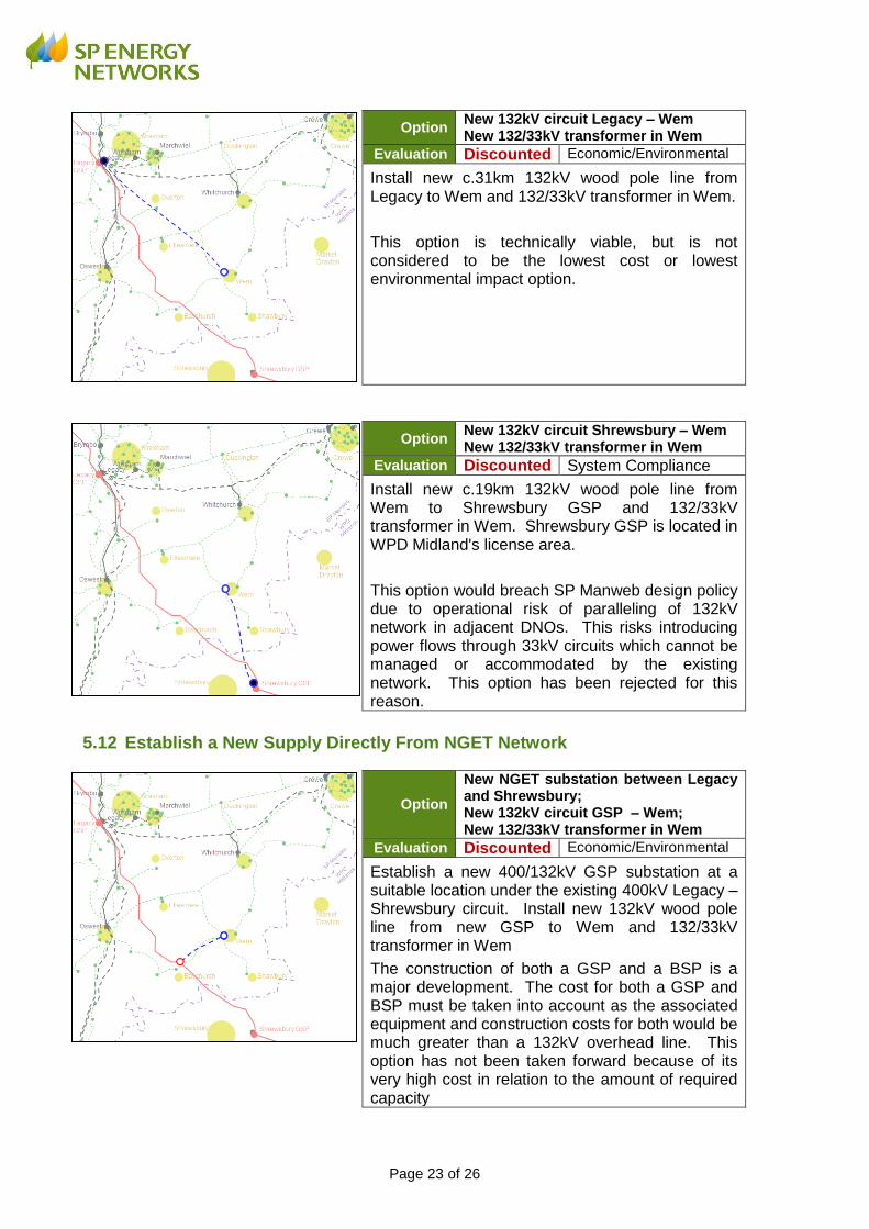
Option New 132kV circuit Legacy – Wem New 132/33kV transformer in Wem
Evaluation Discounted Economic/Environmental
Install new c.31km 132kV wood pole line from Legacy to Wem and 132/33kV transformer in Wem.
This option is technically viable, but is not considered to be the lowest cost or lowest environmental impact option.
Option New 132kV circuit Shrewsbury – Wem New 132/33kV transformer in Wem
Evaluation Discounted System Compliance
Install new c.19km 132kV wood pole line from Wem to Shrewsbury GSP and 132/33kV transformer in Wem. Shrewsbury GSP is located in WPD Midland's license area.
This option would breach SP Manweb design policy due to operational risk of paralleling of 132kV network in adjacent DNOs. This risks introducing power flows through 33kV circuits which cannot be managed or accommodated by the existing network. This option has been rejected for this reason.
5.12 Establish a New Supply Directly From NGET Network
Option
New NGET substation between Legacy and Shrewsbury; New 132kV circuit GSP – Wem; New 132/33kV transformer in Wem
Evaluation Discounted Economic/Environmental
Establish a new 400/132kV GSP substation at a suitable location under the existing 400kV Legacy – Shrewsbury circuit. Install new 132kV wood pole line from new GSP to Wem and 132/33kV transformer in Wem
The construction of both a GSP and a BSP is a major development. The cost for both a GSP and BSP must be taken into account as the associated equipment and construction costs for both would be much greater than a 132kV overhead line. This option has not been taken forward because of its very high cost in relation to the amount of required capacity

Page 24 of 26
6 Conclusions
This report considers potential reinforcement solutions to the electricity distribution network in
order to accommodate growing demand in the Oswestry, Whitchurch and Wem areas in
North Shropshire, and hence support and enable growth across these areas. Twelve
possible options are considered and are analysed taking into account system compliance,
economic, technical and environmental considerations.
The proposed option is an £18m investment to reinforce the electricity distribution network by
constructing a scheme comprising a 132 kV circuit (underground cable section and wood
pole overhead line), providing support to the existing 33 kV and 11 kV electricity distribution
networks by increasing the capacity available throughout the North Shropshire area.
This report is an updated version of the document that was previously published in May
2016. The options considered in 2016 have been reviewed in light of predicted changes in
demand, and the preferred option is unchanged compared with the conclusions of the 2016
report.
Page 25 of 26
Appendix 1 – North Shropshire Environmental Constraints