Refrigerant Leak Detection System (RLDS) … Leak Detection System (RLDS) Installation and Operation...
82
026-1309 Rev 7 24-MAR-2014 Refrigerant Leak Detection System (RLDS) Installation and Operation Manual
Transcript of Refrigerant Leak Detection System (RLDS) … Leak Detection System (RLDS) Installation and Operation...

026-1309 Rev 7 24-MAR-2014
Refrigerant Leak Detection System (RLDS)Installation and Operation Manual


Emerson Climate Technologies Retail Solutions1065 Big Shanty Road NW, Suite 100
Kennesaw, GA 30144, USA
Phone: 770-425-2724Fax: 770-425-9319
CE/FCC Compliance Notice Information Class A compliance for RLDS under CE Requirements. Meets Part 15 Subpart B requirements of the FCC Rules. In a
domestic environment this product may cause radio interference in which case the user may be required to take adequate measures. ETL, report no 3151009LAX-001 to:
ANSI/UL 61010-1
CAN/CSA 22.2 No 61010-1 & CE Mark
READ ALL INSTRUCTIONS CAREFULLYIf the equipment is not used in the manner specified by the manufacturer, the protection provided by the equipment may be impaired.


Table of Contents1 INTRODUCTION.......................................................................................................................................................... 1
1.1. HOW TO USE THIS MANUAL ........................................................................................................................................ 11.2. NOTES........................................................................................................................................................................... 11.3. SAFETY PRECAUTIONS.................................................................................................................................................. 1
1.3.1. AC Power Supply .................................................................................................................................................. 11.3.2. Protective Grounding............................................................................................................................................ 11.3.3. Explosive Atmosphere ........................................................................................................................................... 11.3.4. Proper Exhaust Venting ........................................................................................................................................ 11.3.5. Working Inside Instrument.................................................................................................................................... 11.3.6. Misuse and Modifications to the Instrument......................................................................................................... 11.3.7. In Case of Malfunction.......................................................................................................................................... 11.3.8. RLDS Fusing ......................................................................................................................................................... 21.3.9. Installation Category ............................................................................................................................................ 21.3.10. Altitude Limit....................................................................................................................................................... 21.3.11. Cleaning .............................................................................................................................................................. 2
1.4. WARNING AND CAUTION STATEMENTS ....................................................................................................................... 21.4.1. Warning Statements .............................................................................................................................................. 21.4.2. Caution Statements ............................................................................................................................................... 2
2 FUNCTIONAL OVERVIEW ....................................................................................................................................... 3
2.1. GENERAL DESCRIPTION................................................................................................................................................ 32.2. COMMUNICATION OPTIONS .......................................................................................................................................... 32.3. UNDERSTANDING MONITORING LEVELS ...................................................................................................................... 32.4. RESPONSE TO THE PRESENCE OF MULTIPLE REFRIGERANTS ....................................................................................... 42.5. SUGGESTED LOCATION OF SAMPLING POINTS ............................................................................................................. 4
3 RLDS INSTALLATION ............................................................................................................................................... 6
3.1. RLDS - INSTALLATION CONSIDERATIONS ................................................................................................................... 63.1.1. Warnings and Cautions......................................................................................................................................... 63.1.2. Inspection .............................................................................................................................................................. 63.1.3. Monitor Location .................................................................................................................................................. 6
3.2. RLDS MOUNTING INSTRUCTIONS ................................................................................................................................ 63.2.1. Screw Locations .................................................................................................................................................... 63.2.2. Installation ............................................................................................................................................................ 7
3.3. RLDS - CONNECTING AIR LINES ................................................................................................................................. 73.3.1. Overview ............................................................................................................................................................... 73.3.2. Tubing Considerations.......................................................................................................................................... 73.3.3. Connecting Purge Line ......................................................................................................................................... 73.3.4. Connecting Exhaust Line ...................................................................................................................................... 83.3.5. Connecting Sample Intake Lines........................................................................................................................... 83.3.6. Considerations ...................................................................................................................................................... 8
3.4. SPLITTER KITS .............................................................................................................................................................. 93.4.1. Overview ............................................................................................................................................................... 93.4.2. Installation ............................................................................................................................................................ 9
3.5. RLDS INTERIOR ......................................................................................................................................................... 103.6. RLDS ELECTRICAL WIRING....................................................................................................................................... 11
3.6.1. Warnings and Cautions....................................................................................................................................... 11
4 CONNECTING COMMUNICATION DEVICES ................................................................................................... 13
Table of Contents • v
4.1. E2 MODBUS DIRECT SUPPORT FOR RLDS .............................................................................................................. 134.1.1. Network Connection to E2 .................................................................................................................................. 13
4.1.1.1. COM Port Associations - E2 Versions 3.xx and Below ................................................................................................... 134.1.1.2. COM Port Associations - E2 Versions 4.0 and Above..................................................................................................... 134.1.1.3. E2 Termination ................................................................................................................................................................. 14
4.1.2. E2 Setup of RLDS................................................................................................................................................ 144.1.2.1. Set Up Network Ports ....................................................................................................................................................... 144.1.2.2. Add and Connect RLDS ................................................................................................................................................... 14
4.2. E2, EINSTEIN, AND REFLECS CONTROLLERS (THE RLDS GATEWAY BOARD) ....................................................... 154.2.1. Powering the Gateway Board ............................................................................................................................. 164.2.2. Gateway Board Networking ................................................................................................................................ 16
4.2.2.1. Changing Terminator Switch Settings .............................................................................................................................. 174.2.2.2. RLDS Node Address......................................................................................................................................................... 17
4.2.3. Connecting to an E2, Einstein, or REFLECS Site Controller............................................................................. 174.2.4. Connecting the Gateway Board to the E2, Einstein, or REFLECS Network ...................................................... 18
4.2.4.1. Wire Connection ............................................................................................................................................................... 184.2.4.2. Setting the Board Numbering Dip Switch ........................................................................................................................ 184.2.4.3. Setting the Baud Rate Dip Switches ................................................................................................................................. 194.2.4.4. Setting the RS485 I/O Termination Jumpers .................................................................................................................... 20
4.2.5. Gateway Board Status LEDs............................................................................................................................... 204.2.5.1. The General Status LED ................................................................................................................................................... 204.2.5.2. The Alarm LED ................................................................................................................................................................ 204.2.5.3. RS485 I/O Network Status LED....................................................................................................................................... 214.2.5.4. Receiver Bus Network Status LED................................................................................................................................... 21
5 RLDS - CONNECTING EXTERNAL ALARMS..................................................................................................... 22
5.1. OVERVIEW .................................................................................................................................................................. 225.2. CONNECTION............................................................................................................................................................... 22
6 RLDS HARDWARE SPECIFICATIONS................................................................................................................. 23
7 PROGRAMMING SETUP AND UI NAVIGATION FOR RLDS - DISPLAY SCREENS.................................. 25
7.1. NAVIGATION KEYS ..................................................................................................................................................... 257.2. INITIAL POWER UP...................................................................................................................................................... 257.3. NAVIGATE TO THE FIRST SETUP SCREEN ................................................................................................................... 257.4. NAVIGATE TO THE SECOND SETUP SCREEN ............................................................................................................... 267.5. LOCATION ................................................................................................................................................................... 267.6. NUMBER OF ZONES INSTALLED.................................................................................................................................. 267.7. ALARM ACKNOWLEDGE (ACK) - MODE..................................................................................................................... 267.8. AUDIBLE ALARM ........................................................................................................................................................ 267.9. ZONE HOLD MODE ..................................................................................................................................................... 277.10. ZONE HOLD TIME ..................................................................................................................................................... 277.11. DETECTION LIMIT ..................................................................................................................................................... 277.12. LOOP2 FACTOR ......................................................................................................................................................... 277.13. RE-ZERO MODE ........................................................................................................................................................ 277.14. NAVIGATING TO THE THIRD SETUP SCREEN ............................................................................................................ 287.15. SERVICE TIMEOUT .................................................................................................................................................... 287.16. NODE ADDRESS ........................................................................................................................................................ 287.17. PASSWORD ................................................................................................................................................................ 287.18. ACCESSING ADDITIONAL FEATURES ........................................................................................................................ 287.19. DET DIGIPOT............................................................................................................................................................ 297.20. SENSOR TEMPERATURE COEFFICIENT ...................................................................................................................... 297.21. ACQUIRING TEMPERATURE COEFFICIENT (FACTORY USE ONLY) ........................................................................... 297.22. IR DIGIPOT................................................................................................................................................................ 29
8 GENERAL OPERATION OF RLDS - UI................................................................................................................. 30
vi • RLDS I&O Manual 026-1309 Rev 7 24-MAR-2014
8.1. FUNCTIONAL OVERVIEW ............................................................................................................................................ 308.2. THE ZONE SCREEN ..................................................................................................................................................... 30
8.2.1. Location .............................................................................................................................................................. 308.2.2. Refrigerant Type ................................................................................................................................................. 308.2.3. Distance .............................................................................................................................................................. 308.2.4. Zone Temperature ............................................................................................................................................... 308.2.5. Current Detection Reading ................................................................................................................................. 308.2.6. Log Interval......................................................................................................................................................... 31
8.3. NAVIGATING TO THE SECOND HOME SCREEN ........................................................................................................... 318.3.1. Leak Level ........................................................................................................................................................... 318.3.2. Spill Level............................................................................................................................................................ 318.3.3. Evacuation Level................................................................................................................................................. 318.3.4. Resetting the Peak PPM Value ........................................................................................................................... 31
8.4. ALARM CONDITIONS .................................................................................................................................................. 328.5. FAULT CONDITIONS.................................................................................................................................................... 328.6. ALARMS...................................................................................................................................................................... 32
8.6.1. Functional Overview........................................................................................................................................... 328.6.2. Responding to Alarms ......................................................................................................................................... 328.6.3. Alarm Detail Screen............................................................................................................................................ 338.6.4. Acknowledging Alarms ....................................................................................................................................... 33
8.7. SYSTEM FAULTS ......................................................................................................................................................... 338.7.1. Functional Overview........................................................................................................................................... 338.7.2. Navigating to the Fault Screen ........................................................................................................................... 34
8.7.2.1. Critical Faults.................................................................................................................................................................... 348.7.2.2. Non-Critical Faults............................................................................................................................................................ 34
8.7.3. Reset to Factory Default Settings........................................................................................................................ 358.7.3.1. Resetting the RLDS .......................................................................................................................................................... 35
8.7.4. Clearing System Faults ....................................................................................................................................... 358.7.5. Viewing Fault Log............................................................................................................................................... 358.7.6. Viewing Flow Log ............................................................................................................................................... 36
8.8. THE TREND SCREEN ................................................................................................................................................... 368.8.1. Navigating to the Trend Screen .......................................................................................................................... 36
8.9. THE CALIBRATION SCREEN ........................................................................................................................................ 368.9.1. Overview ............................................................................................................................................................. 368.9.2. Navigating to the Calibration Screen ................................................................................................................. 378.9.3. Adjusting Calibration Factor.............................................................................................................................. 378.9.4. CO2 Atmospheric Concentration (RLDS-CO2 Units Only) ................................................................................................................................................. 378.9.5. Calibration Procedure ........................................................................................................................................ 378.9.6. Programming New Gases ................................................................................................................................... 38
8.10. THE DIAGNOSTIC SCREEN ........................................................................................................................................ 398.10.1. Navigating to the Diagnostic Screen ................................................................................................................ 398.10.2. Diagnostic Screen Overview............................................................................................................................. 39
8.11. SERVICE MODE......................................................................................................................................................... 40
9 QUICK SETUPS FOR HAND-HELD TERMINAL (HHT).................................................................................... 47
9.1. TIME/DATE SETUP ...................................................................................................................................................... 479.2. ZONE SETUP ............................................................................................................................................................... 47
9.2.1. General Configuration 1 Screen ......................................................................................................................... 479.2.2. General Configuration 2 Screen ......................................................................................................................... 489.2.3. Zone Config Screen 1.......................................................................................................................................... 489.2.4. Zone Config Screen 2.......................................................................................................................................... 49
9.3. STATUS OPTION SCREEN ....................................................................................................................................... 499.3.1. Zone Status Screen .............................................................................................................................................. 49
Table of Contents • vii

9.3.2. General Controller (CTRL STATUS) Screen ...................................................................................................... 50
10 HAND-HELD TERMINAL (HHT) FOR USE WITH THE GATEWAY AND RLDS CONTROLLER......... 51
10.1. HHT KEY OPERATIONS ............................................................................................................................................ 51
11 MAIN SCREENS ....................................................................................................................................................... 52
11.1. HOME SCREEN (F1 SCREEN)..................................................................................................................................... 5211.2. RLDS ENABLE SCREEN............................................................................................................................................ 5211.3. SELECT RLDS SCREEN (F2 SCREEN)..................................................................................................................... 5211.4. OPERATION SELECT (OPTION) SCREEN .................................................................................................................. 53
11.4.1. RLDS STATUS (STATUS OPTION) Screen...................................................................................................... 5311.4.2. RLDS FAULTS (SYSTEM FAULTS) screen...................................................................................................... 5311.4.3. RLDS Configuration Option (CONFIG OPTION) Screen................................................................................ 5411.4.4. General Configuration 1 Screen ....................................................................................................................... 5411.4.5. General Configuration 2 Screen ....................................................................................................................... 5411.4.6. Zone Config Screen 1 ........................................................................................................................................ 5511.4.7. Zone Config Screen 2 ........................................................................................................................................ 5511.4.8. Time/Date Screen .............................................................................................................................................. 5611.4.9. Calibrate Gas Screen 1 ..................................................................................................................................... 5611.4.10. Calibrate Gas Screen 2 ................................................................................................................................... 5611.4.11. Calibrate Gas Screen 3 ................................................................................................................................... 56
11.4.11.1. Calibrate Gas Screen 3 Continued ................................................................................................................................ 5711.5. STATUS OPTION SCREEN ..................................................................................................................................... 57
11.5.1. Zone Status Screen ............................................................................................................................................ 5711.5.2. General Controller (CTRL STATUS) Screen .................................................................................................... 5711.5.3. DIAGNOSTICS Screen 1: Sensor Data Register .............................................................................................. 5811.5.4. Screen 2: Sensor Data Register ........................................................................................................................ 5811.5.5. Screen 3: Sensor Data Register ........................................................................................................................ 5811.5.6. Screen 4: Sensor Data Register ........................................................................................................................ 5911.5.7. Screen 5: Sensor Data Register ........................................................................................................................ 5911.5.8. Screen 6: Sensor Data Register ........................................................................................................................ 5911.5.9. Screen 7: Communication Statistics.................................................................................................................. 59
12 RLDS SETUP ON REFLECS, E2, AND EINSTEIN CONTROLLER INTERFACES ..................................... 60
12.1. REFLECS SETUP FOR RLDS ................................................................................................................................... 6012.2. E2 VERSION 3.01 AND BELOW SETUP FOR RLDS (WITHOUT GATEWAY)................................................................ 6012.3. EINSTEIN SETUP FOR RLDS ..................................................................................................................................... 62
13 RLDS MAINTENANCE............................................................................................................................................ 63
13.1. WARNINGS AND CAUTIONS ...................................................................................................................................... 6313.2. CHARCOAL FILTER ................................................................................................................................................... 6313.3. HYDROPHOBIC FILTER.............................................................................................................................................. 6313.4. SERVICING AIR LINES AND REPLACING TERMINATION FILTERS.............................................................................. 6313.5. ANNUAL MAINTENANCE........................................................................................................................................... 63
13.5.1. Checking Pump and Bench Diagnostics ........................................................................................................... 6313.5.2. Gas Testing........................................................................................................................................................ 6413.5.3. Annual Maintenance Checklist.......................................................................................................................... 65
13.6. REPLACEMENT PARTS AND PART DESCRIPTIONS ..................................................................................................... 66
14 APPENDIX: RLDS CALIBRATION....................................................................................................................... 69
14.1. CALIBRATION CHECK ............................................................................................................................................... 6914.1.1. Testing with Gas Verification Kit...................................................................................................................... 69
INDEX ............................................................................................................................................................................. 71
viii • RLDS I&O Manual 026-1309 Rev 7 24-MAR-2014

1 Introduction
1.1. How to Use This Manual
This manual provides important information on how to install, operate, and service the RLDS.
Please read this manual carefully before use.If you have a working knowledge of refrigerant
monitors, you will find this manual useful as a refer-ence tool. If you are new to the use of refrigerant mon-itors, you can educate yourself about the principles of refrigerant gas detection and the proper operation of this device by reading this manual thoroughly.
1.2. NotesEmerson Climate Technologies Retail Solutions
reserves the right to change the operation or specifica-tions of this instrument at any time without notice.
If any errors or ambiguities are discovered in this manual, promptly inform Emerson Retail Solutions.
No part of this manual may be reproduced or rec-reated, in any form or by any means, without the ex-press prior permission of Emerson Retail Solutions.
1.3. Safety Precautions
1.3.1. AC Power SupplyEnsure the source voltage matches the voltage of
the product before energizing the equipment.The RLDS uses a universal power supply that is
capable of accepting inputs of 100 to 240 VAC, 50/60 Hz. The monitor’s power consumption is 20 Watts.
It is highly recommended that the RLDS be placed on a separate circuit (with UPS or surge protection) and be connected directly to the AC power source.
A switch or circuit breaker rated 1.0 A, 250 VAC, with a minimum terminal spacing of 3.0 mm must be attached to the monitor’s AC power leads. This switch must also be located in close proximity to the
monitor, and be within easy reach of the operator. This switch should also be clearly marked as the mon-itor’s type of equipment.
• A switch or circuit-breaker must be included in the building installation
• The switch must be in close proximity to the equipment and within easy reach of the opera-tor
• The switch must be clearly marked as the dis-connecting device for the equipment
1.3.2. Protective GroundingUnder no circumstances should the RLDS be op-
erated without connection to a protective ground. Do-ing so poses a potential shock hazard and is also a violation of electrical safety standards applicable to this type of equipment.
1.3.3. Explosive AtmosphereDo not operate this equipment in the presence of
flammable liquids, vapors, or aerosols. Operation of any electrical instrument in such an environment con-stitutes a safety hazard.
1.3.4. Proper Exhaust VentingIt is imperative that the exhaust port on this instru-
ment be properly vented as described in this manual. Failure to do so constitutes a safety hazard.
1.3.5. Working Inside InstrumentExtreme care should be exercised when accessing
the interior of the monitor. Only qualified electrical maintenance personnel should perform connections and adjustments. Always de-energize the power sup-ply before opening the monitor’s enclosure.
1.3.6. Misuse and Modifications to the Instrument
The protection provided by the monitor may be impaired if the monitor is used in a manner not spec-ified by Emerson Retail Solutions. Modifications to this monitor, not expressly approved, will void the warranty.
1.3.7. In Case of MalfunctionDo not continue to use this equipment if there are
any symptoms of malfunction or failure. In the case of such occurrence, de-energize the power supply and
How to Use This Manual Introduction • 1
contact a qualified repair technician or the nearest Service Center. ONLY the provided knockouts are to be used for electrical and communication wiring. Drilling into the box will void the warranty.
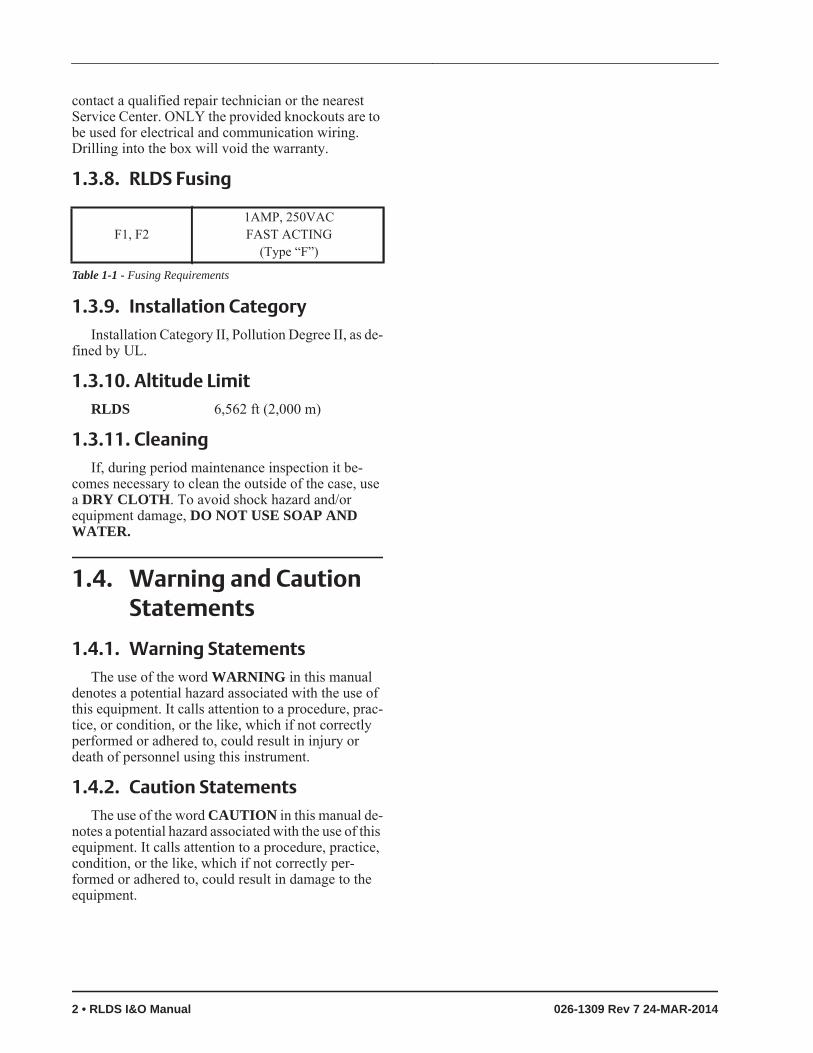
1.3.8. RLDS Fusing
1.3.9. Installation CategoryInstallation Category II, Pollution Degree II, as de-
fined by UL.
1.3.10. Altitude LimitRLDS 6,562 ft (2,000 m)
1.3.11. CleaningIf, during period maintenance inspection it be-
comes necessary to clean the outside of the case, use a DRY CLOTH. To avoid shock hazard and/or equipment damage, DO NOT USE SOAP AND WATER.
1.4. Warning and Caution Statements
1.4.1. Warning StatementsThe use of the word WARNING in this manual
denotes a potential hazard associated with the use of this equipment. It calls attention to a procedure, prac-tice, or condition, or the like, which if not correctly performed or adhered to, could result in injury or death of personnel using this instrument.
1.4.2. Caution StatementsThe use of the word CAUTION in this manual de-
notes a potential hazard associated with the use of this equipment. It calls attention to a procedure, practice, condition, or the like, which if not correctly per-formed or adhered to, could result in damage to the equipment.
F1, F2 1AMP, 250VAC FAST ACTING
(Type “F”)
Table 1-1 - Fusing Requirements
2 • RLDS I&O Manual 026-1309 Rev 7 24-MAR-2014
2 Functional Overview
2.1. General DescriptionRefrigerant monitors are specified to support com-
pliance to federal, state and local safety codes govern-ing refrigerant emissions. Avoiding significant refrigerant loss reduces equipment replacement costs, maintains equipment efficiency, promotes safety, and protects the environment.
The RLDS provides for the continuous monitoring of refrigerant gas levels in up to 16 separate test zones or channels. The instrument is easily programmed to monitor a variety of gases and independent leak (small), spill (medium), and evacuation (large) levels may be designated for each zone. The instrument also retains a log of previous readings that can be easily accessed for analysis.
An audible alarm and front panel indicators are provided to signal alarm and fault conditions, and re-lay contacts are provided that can be used to trigger external alarm devices in the event of a system fault, or if a leak (small), spill (medium), or evacuation (large) level of gas is detected. The system also may be fitted with an optional two-channel 4-20mA cur-rent loop board for connection to remote monitoring equipment.
The RLDS requires only minor periodic mainte-nance such as the occasional replacement of filters. The monitor incorporates active diagnostics that con-tinuously monitor the system for proper operation. A front panel indicator is provided to alert an operator of system malfunctions, and fault codes are generated that enable the user to identify the cause of the fault.
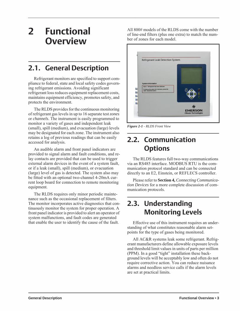
All 800# models of the RLDS come with the number of line-end filters (plus one extra) to match the num-ber of zones for each model.
2.2. Communication Options
The RLDS features full two-way communications via an RS485 interface. MODBUS RTU is the com-munication protocol standard and can be connected directly to an E2, Einstein, or REFLECS controller.
Please refer to Section 4, Connecting Communica-tion Devices for a more complete discussion of com-munication protocols.
2.3. Understanding Monitoring Levels
Effective use of this instrument requires an under-standing of what constitutes reasonable alarm set-points for the type of gases being monitored.
All AC&R systems leak some refrigerant. Refrig-erant manufacturers define allowable exposure levels and threshold limit values in units of parts per million (PPM). In a good “tight” installation these back-ground levels will be acceptably low and often do not require corrective action. You can reduce nuisance alarms and needless service calls if the alarm levels are set at practical limits.
Figure 2-1 - RLDS Front View
General Description Functional Overview • 3

Recommended monitoring levels based on com-pliance to ANSI/BSR ASHRAE 15-2007 and ASHRAE Safety Code 34-2007 have been developed and are listed in Table 8-1 and Section 6, RLDS Hard-ware Specifications.
Setting the unit at these recommended alarm levels will satisfy the needs of most users. However, the PPM levels generated by system leaks into the envi-ronment are greatly influenced by the volume of air in the sampling area, air circulation, size of the leak, dis-tance to the monitoring point, and a host of other vari-ables. In some cases the set points may need to be adjusted either up or down to achieve effective moni-toring. Please contact your representative (770-425-2724) for assistance in obtaining these levels.
2.4. Response to the Presence of Multiple Refrigerants
The RLDS is a refrigerant level monitor, not a gas analyzer. You must program the monitor to test for a specific refrigerant in each zone, and it will only re-turn accurate concentration readings for that particu-lar refrigerant. If a leak occurs of another refrigerant gas type, the monitor may return false readings.
Most applications only require detection of a sin-gle refrigerant and the problems that are associated with monitoring multiple gases are rarely an issue. If there is a possibility of multiple refrigerants leaking in the same sampling zone, you should consider careful-ly which refrigerant compound you program the unit to monitor, or make system design considerations to cover this event. Please consult your sales engineer for assistance in setting up the RLDS system to cover this event.
2.5. Suggested Location of Sampling Points
At the point of origin of a refrigerant leak, the gas is highly concentrated. As the refrigerant is dispersed into the air, the gas molecules diffuse, causing a dilu-tion of the original concentration. The RLDS mea-sures the refrigerant concentration at the sample collection point, so if the termination of the collection
line is not at the exact point of the refrigerant leak, the unit will read a diluted mixture of the refrigerant gas and air and may require adjustment of alarm levels.
The farther away an RLDS sample point is from a refrigerant leak, the longer it will take to detect the leak, and the lower the concentration of refrigerant in the air will be; therefore, place the termination of the collection line as near as possible to the point where refrigerant leaks are the most likely.
It should also be noted that refrigerant gas is heavi-er than air and tends to collect below the point of a leak; therefore, samples taken near the floor will have a greater concentration of gas than those collected above the source of a leak; therefore, sampling points should ideally be located as close as possible to the source of potential leaks. If this is impractical, then the alarm setpoints should be adjusted for that zone to compensate for the dilution of the refrigerant gas. Line-end filters should be mounted 12” (30 cm) to 18” (45 cm) above the floor. DO NOT block any of the zones. Unused zones may be disabled by setting the distance parameter to zero feet in the zone setup screen.
The RLDS should be centrally located in the me-chanical room and be readily accessible for easy visu-al monitoring and servicing. The combined length of sample tubing, plus exhaust tubing, should not exceed 1200 feet (365 meters) for any zone. The fresh air purge line should draw from an area that does not con-tain any refrigerant gas. The exhaust line should run to an outside location if possible. The combined length of the purge line and the exhaust line cannot exceed 300 feet (91 meters).
Ideally, two to three pick up points spaced around each chiller will provide sufficient coverage. It may be necessary to perform a “smoke” test of the me-chanical room to determine the best locations. The smoke test would provide the pattern of air currents present in the mechanical room.
NOTE: For information about using the RLDS in wet locations, see Section 3.3.6., Con-siderations.
4 • RLDS I&O Manual 026-1309 Rev 7 24-MAR-2014
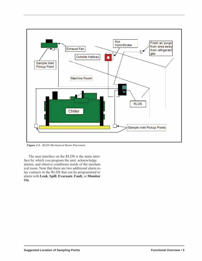
The user interface on the RLDS is the main inter-face by which you program the unit, acknowledge alarms, and observe conditions inside of the mechan-ical room. Note that there are two additional alarm re-lay contacts in the RLDS that can be programmed to alarm with Leak, Spill, Evacuate, Fault, or Monitor On.
Figure 2-2 - RLDS Mechanical Room Placement
Suggested Location of Sampling Points Functional Overview • 5

3 RLDS Installation
Standard accessories needed for a four (4)-point System:
3.1. RLDS - Installation Considerations
3.1.1. Warnings and Cautions
3.1.2. InspectionThe RLDS has been thoroughly inspected and test-
ed prior to shipment from the factory. Nevertheless, it is recommended that the monitor be re-checked prior to installation. Inspect the outside of the enclosure to make sure there are no obvious signs of shipping dam-age. Open the enclosure and inspect the interior of the unit for loose components that may have become dis-lodged during shipment. If damage is discovered, please contact Technical Support for assistance (770-425-2724).
3.1.3. Monitor LocationThe RLDS should be centrally located in the facil-
ity and should be easily accessible for visual monitor-ing and servicing. Intake sample lines can be up to 1200 feet (365 meters), but it is important to remem-ber that sampling cycle time is proportional to the to-tal number and length of individual sample lines.
Dirt, grease, and oils can adversely affect the op-eration of the RLDS. The monitor should be installed out of direct sunlight in a clean, dry area that is not subject to temperature or humidity extremes. Installa-tion of the monitor in a mechanical room is acceptable provided reasonable environmental conditions exist. If there is a question, consider installing the unit out-side of the mechanical room in a cleaner area of the facility. The location should allow the monitor to be easily accessible for visual monitoring and servicing.
3.2. RLDS Mounting Instructions
3.2.1. Screw LocationsThe RLDS should be installed plumb and level
and securely fastened to a rigid mounting surface. The enclosure utilizes keyhole mounting brackets de-signed for 1/4” (6.35 mm) fasteners. Locate the four
Figure 3-1 - RLDS Diagram
Accessory Part NumberFive (5) Line-End Filters (Assembly)
275-0300
Charcoal Filter 275-0275
RLDS Instruction Manual 026-1309
Table 3-1 - RLDS Accessories and Part Numbers
WARNING: Explosion hazard! Do not mount or operate this equipment in an area that may contain or in the presence of flammable liq-
uids, vapors, or aerosols. Operation of any electrical equipment in such an environment constitutes a safety hazard.
WARNING: Drilling holes in the RLDS enclo-sure may damage the unit and will void the warranty. Please use the knockouts provided for electrical connections.
WARNING: Shock hazard! Always de-ener-gize the power supply before working on the in-terior of the equipment.
CAUTION: The RLDS contains sensitive elec-tronic components that can be easily damaged. Do not to touch nor disturb any of these com-ponents.
6 • RLDS I&O Manual 026-1309 Rev 7 24-MAR-2014

screws as shown in the diagram below and allow the screw heads to protrude approximately 1/4” (6.35 mm).
3.2.2. InstallationHold the monitor flat against the mounting surface
and allow it to slide down, engaging the screw heads in the keyhole slots of the mounting brackets. Adjust the screws as necessary to hold the monitor securely against the mounting surface.
3.3. RLDS - Connecting Air Lines
3.3.1. OverviewIndividual sample lines are run from the RLDS to
each area of the facility to be monitored. Additionally, a purge line is installed to provide clean air for reset-ting the infrared zero baseline. An exhaust line is in-stalled to vent residual gas away from the monitor. All air line connections, located on the left side of the en-
closure, are indicated in Figure 3-3.
3.3.2. Tubing ConsiderationsUse 1/4” (6.35 mm) outside diameter (0.04” wall)
(1.02 mm wall) flex tubing for all air lines or equiva-lent. The tubing should be clean and free of residual moisture or other contaminants. The tubing should be cut cleanly with a sharp knife and care should be tak-en not to distort the tubing end.
To connect the air lines to the monitor simply push the tubing firmly onto the connector. To remove a line, depress the plastic ring on the connector with one hand while withdrawing the tube with your other hand. All tubing bends should have a radius of no less than 5” (12 cm) to ensure proper airflow. If kinks or obstructions occur in any of the air lines, the instru-ment may not function properly.
3.3.3. Connecting Purge LineA purge line is required to draw fresh air into the
instrument and should not exceed 300 feet (91 meters) in length. A charcoal filter assembly has been provid-
Figure 3-2 - RLDS Mounting Dimensions
Figure 3-3 - RLDS (Tubing Connections)
RLDS - Connecting Air Lines RLDS Installation • 7

ed to ensure clean air is being drawn in through the purge line. This filter should be mounted close to the RLDS.
It is advisable to terminate the purge line outdoors, provided the input is not exposed to rain, snow, ice, exhaust fumes, or other airborne contaminates. If an outdoor installation is impractical, the line should be run to an area inside the facility that you are certain is not contaminated with ambient refrigerant gas.
A line-end filter should be attached to the end of the purge line. If this is not possible, an optional char-coal filter assembly (P/N 275-0275) can be used to fil-ter refrigerant from the purge line, and may be mounted adjacent to the monitor. A line-end filter as-sembly (P/N 275-0300) should be attached to the end of the purge line when the charcoal filter is not used.
3.3.4. Connecting Exhaust LineAn exhaust line (¼” OD tubing) (6.35 mm) can be
used when it is required to vent gas samples away from the instrument and should not exceed 300 feet (91 meters). The exhaust line should terminate in a lo-cation that is completely isolated from the purge line termination point and other areas of the facility that will be monitored. Ideally this line should terminate outdoors in a location that is not exposed to the ele-ments. This line does not require a line-end filter. If the exhaust line terminates outside the building, posi-tion the tubing so that no water or moisture can enter it.
3.3.5. Connecting Sample Intake Lines
The RLDS is designed to accommodate up to 16 separate sample intake lines. The standard configura-tion of the unit includes one manifold of four intake connectors and one purge connector. Additional man-ifolds can be easily installed to increase monitoring capacity. Please contact Technical Assistance (770-425-2724) for more information.
Sample intake lines can be up to 1200 feet (365 meters) when no exhaust tubing is used. Otherwise, the combined length of the sample line and the ex-haust line cannot exceed 1200 feet (365 meters). All line terminations should be positioned to reduce the possibility of mists, aerosols, oil, water, dust, or other contaminates being drawn into the instrument. A line-end filter (included) should be attached to the end of each sample intake line. Line-end filters should be placed 12” to 18” (30 to 45 cm) above the floor.
IMPORTANT: DO NOT block any of the zones. Unused zones may be disabled by setting their length parameter to zero feet in the Zone Setup screen (Sec-tion 8.2., The Zone Screen).
Please refer to the earlier section (Section 2.5., Suggested Location of Sampling Points) to learn more about where to locate the monitoring points.
3.3.6. ConsiderationsFor maximum protection, the RLDS may be shut
down when a System Fault occurs. This might be de-sired, for example, when the RLDS is used in wet lo-cations such as meat preparation rooms. When water is pulled into the system, a System Fault will occur, closing the fault relay located at the bottom of the main control board. To turn power off to the RLDS when this occurs, wire the fault relay into a spare 16AI input. Route the power supply to the RLDS through an 8RO output using the normally closed contacts. Program the E2/Einstein to alarm the fault input on a contact closure and turn on the 8RO output when this occurs. This can be done using a Digital Sensor Control application in the E2/Einstein. Refer to the E2 Installation and Operation manual (P/N 026-1610) for details on setting up a Digital Sensor Con-trol application.
CAUTION: (CO2 Only): Because CO2 is pres-ent in ambient air, the purge line MUST BE run outside, away from any known sources of CO2 gas. An atmospheric CO2 concentration
value can be manually entered by the user in the CAL screen. CO2 is supported by RLDS-CO2 units. See Sec-tion 8.9.4. CO2 Atmospheric Concentration (RLDS-CO2 Units Only).
CAUTION: The introduction of contaminants through the air intake lines can result in seri-ous and permanent damage to the monitor.
8 • RLDS I&O Manual 026-1309 Rev 7 24-MAR-2014

3.4. Splitter Kits
3.4.1. OverviewTwo-way splitter (P/N 275-0304) and three-way
splitter (P/N 275-0305) kits for a zone are used with the RLDS to allow you to pinpoint critical points of the refrigeration system, and allow further monitoring in small spaces with a high probability for leakage. Splitter kits allow you to place more sensors in each zone, which enable potential leaks to be detected more quickly.
3.4.2. InstallationSensors can be installed on walls, drains, or areas
with potential air flow. Any ¼” tubing can be used to configure the two or three point sensors.
The alarm setpoint must be changed due to the av-eraging effect of the splitter system. The pick-up lines for the splitter tube must be the same length from the splitter to each of the end-of-line filters to balance the splitter system and create the averaging effect.
A two-way splitter kit requires reduction of the original alarm setpoint by ½ so the setpoint becomes half of the original value. A three-way splitter kit re-quires reduction of the original setpoint by ⅓ so the setpoint becomes a third of the original value.
For example, if the alarm setpoint alarm value is 1000, with a two-way splitter the value becomes 500 ppm. With a three-way splitter the value becomes 333 ppm.
Figure 3-4 - Types of Splitter Kits
Figure 3-5 - Proper Wire Length of a Two-way Splitter
CAUTION: Keep pick-up tube the same length to create the averaging effect of the splitter sys-tem. Point the filter vertically downward or horizontally with a slight downward tilt to
avoid moisture collecting in the filter from condensa-tion.
Figure 3-6 - Improper Wire Length of a Two-way Splitter
Part Number Description275-0304 Two-way Splitter Kit contains:
1 two-way push-fit splitter, 2 line-end filters(tubing not included)
275-0305 Three-way Splitter Kit contains:1 three-way push-fit splitter, 3 line-end filters(tubing not included)
270-0810 ¼” Sample Tubing (100 ft.)
Table 3-2 - Splitter Kit and Tubing Part Numbers
Splitter Kits RLDS Installation • 9

3.5. RLDS Interior
Figure 3-7 - Diagram of RLDS Interior
Figure 3-8 - RLDS Processor Board Layout Figure 3-9 - Relay, RS485, and AC Input Connections
10 • RLDS I&O Manual 026-1309 Rev 7 24-MAR-2014

3.6. RLDS Electrical WiringThe RLDS uses a universal power supply that is
capable of accepting inputs of 100 to 240 VAC, 50/60 Hz. The monitor's power consumption is 20 Watts. It is highly recommended that the monitor be connected directly to the AC power source, preferably on its own circuit. The AC power connection should be complet-ed with UL approved 3-conductor wire (minimum 16 AWG), rated 300 VAC at 221°F (105°C).
Locate a convenient service knockout and install electrical conduit in the typical manner.
Locate the AC Input Terminals and Ground Stud on the inside of the monitor (Figure 3-7). Secure the incoming AC power neutral (white/blue) and live (black/brown) wires to the LINE 1 and LINE 2 termi-nals.
Using the supplied crimp-on ring terminals, wash-ers, and nuts, connect the incoming AC power ground wire (green) to the monitor's AC input ground stud, and then install a separate wire between the ground stud and the GND terminal.
Locate the AC power connector on the inside of the instrument and remove it from the circuit board. Secure the wire leads to the connector orienting them as shown in the diagram. Carefully plug the connector back onto the circuit board. finally, locate the ground lug and securely fasten the ground lead.
A second connector is provided to wire an external device through the RLDS power circuit. Locate the connector and complete the wiring as described above.
3.6.1. Warnings and Cautions
• A switch or circuit breaker rated 1.0 A, 250 VAC must be attached to the unit’s AC power leads.
• This switch must also be located in close prox-imity to the monitor, and be within easy reach of the operator.
• This switch should also be clearly marked as the unit’s main AC disconnect device. The cir-cuit breaker or switch must disconnect all cur-rent-carrying conductors (i.e., Live and
Figure 3-10 - Switch and Fuse Locations
NOTE: The plastic cable ties surrounding the air pump are to ensure safe handling during shipment. Remove before operating the unit.
Reinstall a plastic cable around the air pump if the unit is shipped back to Emerson Retail Solutions for service or repair. This prevents damage during ship-ment.
NOTE: For more information on power speci-fications, contact your Emerson Retail Solu-tions representative for more information.
WARNING: Electrical installation should be performed by a certified electrician and must comply with all applicable local, state, and federal electrical safety codes.
WARNING: Under no circumstances should this instrument be operated without connection to a protective ground. The AC power ground
wire must first be connected to the monitor's ground stud. Doing so poses a potential shock hazard and is also a violation of electrical safety standards applicable to this type of equipment.
WARNING: Copper conductors for connec-tion to supply mains must be made in accor-dance with NEC/CEC and local codes.
WARNING: Drilling holes in the RLDS enclo-sure may damage the unit and will void the warranty. Only use the knockouts provided for electrical connections.
RLDS Electrical Wiring RLDS Installation • 11

Neutral).
Figure 3-11 - AC Input Power and Ground Connections
12 • RLDS I&O Manual 026-1309 Rev 7 24-MAR-2014
4 Connecting Communication Devices
4.1. E2 MODBUS Direct Support for RLDS
4.1.1. Network Connection to E2Connecting an RLDS to an E2 unit requires the E2
version 3.01 and above. Contact Emerson Retail Solutions for upgrade information if the controller is a version prior to 3.01.
4.1.1.1. COM Port Associations - E2 Versions 3.xx and Below
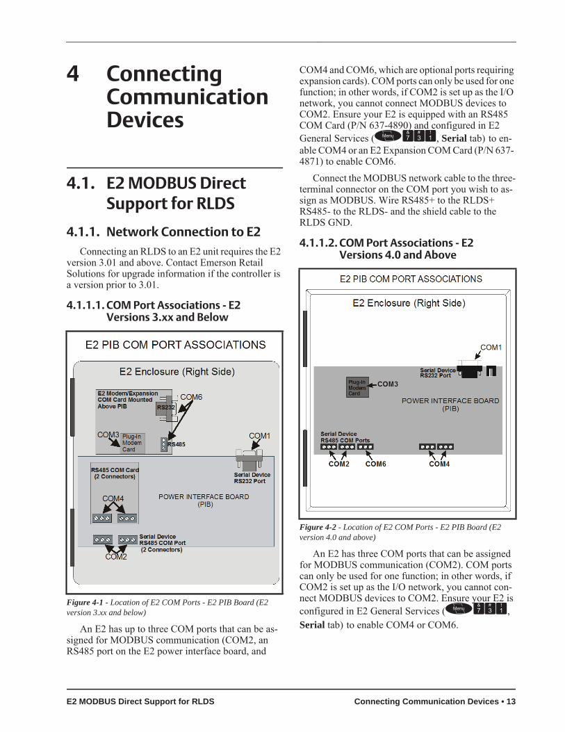
An E2 has up to three COM ports that can be as-signed for MODBUS communication (COM2, an RS485 port on the E2 power interface board, and
COM4 and COM6, which are optional ports requiring expansion cards). COM ports can only be used for one function; in other words, if COM2 is set up as the I/O network, you cannot connect MODBUS devices to COM2. Ensure your E2 is equipped with an RS485 COM Card (P/N 637-4890) and configured in E2 General Services (, Serial tab) to en-able COM4 or an E2 Expansion COM Card (P/N 637- 4871) to enable COM6.
Connect the MODBUS network cable to the three-terminal connector on the COM port you wish to as-sign as MODBUS. Wire RS485+ to the RLDS+ RS485- to the RLDS- and the shield cable to the RLDS GND.
4.1.1.2. COM Port Associations - E2 Versions 4.0 and Above
An E2 has three COM ports that can be assigned for MODBUS communication (COM2). COM ports can only be used for one function; in other words, if COM2 is set up as the I/O network, you cannot con-nect MODBUS devices to COM2. Ensure your E2 is configured in E2 General Services (, Serial tab) to enable COM4 or COM6.
Figure 4-1 - Location of E2 COM Ports - E2 PIB Board (E2 version 3.xx and below)
Figure 4-2 - Location of E2 COM Ports - E2 PIB Board (E2 version 4.0 and above)
E2 MODBUS Direct Support for RLDS Connecting Communication Devices • 13

Connect the MODBUS network cable to the three-terminal connector on the COM port you wish to as-sign as MODBUS. Wire RS485+ to the RLDS+ RS485- to the RLDS- and the shield cable to the RLDS GND.
4.1.1.3. E2 Termination
For E2 versions 3.xx and below, if the E2 will be the first device in the daisy-chain, set the port’s termi-nation jumpers to the TERMINATED & BIASED po-sition (all three jumpers UP); otherwise, set all jumpers DOWN if not the first device.
For E2 versions 4.0 and above, if the E2 is the be-ginning of all RS485 I/O or MODBUS Networks, all three of these jumpers should be set to the UP posi-tion. For MODBUS, the jumpers should all be in the top-most position (MOD). For I/O Net, the jumpers should be in the middle position (I/O). For no termi-nation, set the jumpers to the down position (NO).
4.1.2. E2 Setup of RLDS
4.1.2.1. Set Up Network Ports
Before setting up a RLDS, the port on the E2 that has the MODBUS cable connected must be set up as a MODBUS port.
1. Log in to the E2 with Level 4 access.
2. Press followed by - General Controller Info.
3. Press + to open the Serial tab of the Gen-eral Controller Info setup screens:
4. This screen will have a “Connection” field for all COM ports on the E2. Highlight the COM port connection field that will be used, and press - LOOK UP. From the list of net-work types, select MODBUS.
5. Four fields will become visible underneath the COM port connection field, which pertain to the way the device communicates:
• Baud - Default setting is 19200. Leave this field at the default value.
• Data Size - Leave this field at the default value (8).
• Parity - Leave this field at the default value (None).
• Stop Bits - RLDS value is one (1).
6. Press to save changes and exit.
4.1.2.2. Add and Connect RLDS
To enable communications between E2 and the RLDS, the devices must be added and addressed in E2.
1. Log in to the E2 with Level 4 access.
2. Press - Connected I/O Boards and Controllers.
3. On the ECT tab screen enter the number of RLDS Panels in the RLDS number field.
4. Press to return to the Network Setup menu, then select - Network Summary (Figure 4-5).Figure 4-3 - Serial Communications Manager Screen
Figure 4-4 - Connected I/O Screen
14 • RLDS I&O Manual 026-1309 Rev 7 24-MAR-2014

5. Locate the RLDS you added to the network list (press and to scroll through the list) and highlight with the cursor. Press for Set-up.
Each RLDS is assigned a MODBUS address auto-matically when it is created.
6. Locate the RLDS you set up, and look at each device’s status in the Status field. You will see one of the following messages:
• Online - The RLDS is communicating nor-mally.
• Offline - The RLDS is not communicating, has not been commissioned, is not func-tional, or is not powered up. Verify the RLDS is powered up, wired correctly, and has the proper network address, baud rate, and parity.
• No Port - No port is set up in the E2 Serial Configuration Manager to be a MODBUS port.
7. To commission the device, select - Commission and choose the MODBUS net-work address.
4.2. E2, Einstein, and REFLECS Controllers (The RLDS Gateway Board)
The RLDS may be connected to a Emerson Retail Solutions controller using a Gateway Board. The Gateway Board is a special interface device that al-lows an E2, Einstein, or REFLECS site controller to communicate with up to three RLDS units as if each of them were a standard 16AI Analog Input board, and allows for programming with the Hand-Held Ter-minal (HHT).
The Gateway Board communicates with the RLDS units via the MODBUS network, which is con-nected to the Gateway’s “Receiver Bus” network ter-minal. The Gateway communicates with site controllers (E2, Einstein, or REFLECS) via the RS485 I/O Network (COM A & COM D for RE-FLECS).
Figure 4-5 - Network Summary Screen
Figure 4-6 - RLDS Gateway Board Layout (P/N 810-3760)
NOTE: Before installing the Gateway board, verify that jumper JP7 (if present on the board) is set to the “NORMAL” position (not the “TEST” position). Operating the Gateway with
the jumper in TEST position may cause board damage.
E2, Einstein, and REFLECS Controllers (The RLDS Gateway Board) Connecting Communication Devices • 15
In addition to being an interface with the site con-troller, the Gateway Board also allows you use a Hand-held Terminal (HHT) device to program the RLDS and view status.
4.2.1. Powering the Gateway Board
The Gateway board requires 24VAC power from a Class 2 center-tapped transformer.
Emerson Retail Solutions supplies several sizes of center-tapped transformers for powering multiple 16AIs, 8ROs, and other RS485 peripheral boards of the E2, Einstein, and REFLECS systems.
Refer to your controller’s user manual for infor-mation on how to use the center-tapped transformers listed in Table 4-2 to power multiple RS485 I/O de-vices.
Figure 4-7 shows how to connect the 56VA and 80VA transformers to the Gateway power connector.
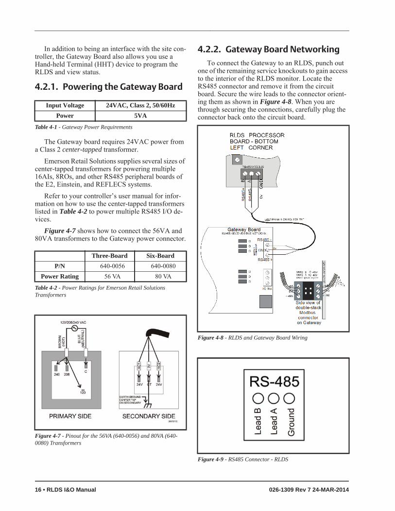
4.2.2. Gateway Board NetworkingTo connect the Gateway to an RLDS, punch out
one of the remaining service knockouts to gain access to the interior of the RLDS monitor. Locate the RS485 connector and remove it from the circuit board. Secure the wire leads to the connector orient-ing them as shown in Figure 4-8. When you are through securing the connections, carefully plug the connector back onto the circuit board.
Input Voltage 24VAC, Class 2, 50/60HzPower 5VA
Table 4-1 - Gateway Power Requirements
Three-Board Six-BoardP/N 640-0056 640-0080
Power Rating 56 VA 80 VA
Table 4-2 - Power Ratings for Emerson Retail Solutions Transformers
Figure 4-7 - Pinout for the 56VA (640-0056) and 80VA (640-0080) Transformers
Figure 4-8 - RLDS and Gateway Board Wiring
Figure 4-9 - RS485 Connector - RLDS
16 • RLDS I&O Manual 026-1309 Rev 7 24-MAR-2014

4.2.2.1. Changing Terminator Switch Settings
The terminator switch is shipped from the factory in the terminated or DOWN position. This is the cor-rect setting if the RLDS is connected to a single de-vice, or it is the last device on the network chain. If the RLDS is to be installed in the middle of a network, the terminator must be moved to the UP position. Locate switch 4 and determine its position. If it needs to be moved, slide the switch to the appropriate position.
4.2.2.2. RLDS Node Address
The node address is set through the front display of the RLDS unit. Refer to Section 7.16., Node Address for more information.
4.2.3. Connecting to an E2, Einstein, or REFLECS Site Controller
Up to three RLDS units may be connected to a site controller via the Gateway Board. The node address switch on each RLDS must be set in succession from 1 to 3 in order for the Gateway Board to recognize the units on the network.
Termination
The three RLDS units and the Gateway Board are connected serially via MODBUS. If an RLDS is at the end of the network segment, terminate the unit by set-ting the termination switch to the DOWN position. Otherwise, set the termination switch to the UP posi-tion to leave the unit unterminated.
Figure 4-10 - Positioning the Termination Switch - RLDS
NOTE: If connecting RLDS units to a Emer-son Retail Solutions site controller network, you MUST number the units from 1-3. The Gateway Board will not recognize any RLDS
unit with a number that is not 1, 2, or 3.
Figure 4-11 - RLDS Units Connected to Gateway, Site Controller
E2, Einstein, and REFLECS Controllers (The RLDS Gateway Board) Connecting Communication Devices • 17
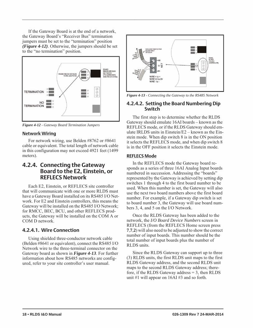
If the Gateway Board is at the end of a network, the Gateway Board’s “Receiver Bus” termination jumpers must be set to the “termination” position (Figure 4-12). Otherwise, the jumpers should be set to the “no termination” position.
Network Wiring
For network wiring, use Belden #8762 or #8641 cable or equivalent. The total length of network cable in this configuration may not exceed 4921 feet (1499 meters).
4.2.4. Connecting the Gateway Board to the E2, Einstein, or REFLECS Network
Each E2, Einstein, or REFLECS site controller that will communicate with one or more RLDS must have a Gateway Board installed on its RS485 I/O Net-work. For E2 and Einstein controllers, this means the Gateway will be installed on the RS485 I/O Network; for RMCC, BEC, BCU, and other REFLECS prod-ucts, the Gateway will be installed on the COM A or COM D network.
4.2.4.1. Wire Connection
Using shielded three-conductor network cable (Belden #8641 or equivalent), connect the RS485 I/O Network wire to the three-terminal connector on the Gateway board as shown in Figure 4-13. For further information about how RS485 networks are config-ured, refer to your site controller’s user manual.
4.2.4.2. Setting the Board Numbering Dip Switch
The first step is to determine whether the RLDS Gateway should emulate 16AI boards – known as the REFLECS mode, or if the RLDS Gateway should em-ulate IRLDS units in Einstein/E2 – known as the Ein-stein mode. When dip switch 8 is in the ON position it selects the REFLECS mode, and when dip switch 8 is in the OFF position it selects the Einstein mode.
REFLECS Mode
In the REFLECS mode the Gateway board re-sponds as a series of three 16AI Analog Input boards numbered in succession. Addressing the “boards” represented by the Gateway is achieved by setting dip switches 1 through 4 to the first board number to be used. When this number is set, the Gateway will also use the next two board numbers above the first board number. For example, if a Gateway dip switch is set to board number 3, the Gateway will use board num-bers 3, 4, and 5 on the I/O Network.
Once the RLDS Gateway has been added to the network, the I/O Board Device Numbers screen in REFLECS (from the REFLECS Home screen press 7,7,2) will also need to be adjusted to show the correct number of input boards. This number should be the total number of input boards plus the number of RLDS units.
Since the RLDS Gateway can support up to three (3) RLDS units, the first RLDS unit maps to the first RLDS Gateway address, and the second RLDS unit maps to the second RLDS Gateway address; there-fore, if the RLDS Gateway address = 3, then RLDS unit #1 will appear on 16AI #3 and so forth.
Figure 4-12 - Gateway Board Termination Jumpers
Figure 4-13 - Connecting the Gateway to the RS485 Network
18 • RLDS I&O Manual 026-1309 Rev 7 24-MAR-2014

If you are not using all three RLDS units, you can disable them on the Gateway (see Section 11.2., RLDS Enable Screen). If they are disabled on the RLDS Gateway, then the corresponding addresses are free to be used by other 16AI boards.
Note that because the Gateway reserves three 16AI Board numbers for its own use, an I/O Network with a Gateway is limited to thirteen (13) 16AI boards. Note also that since 16 is the highest board number possible, a Gateway’s dip switch may not be set to any number above 14.
Einstein Mode
In the Einstein mode the Gateway board responds as a series of three IRLDS units numbered in succes-sion. Addressing the “boards” represented by the Gateway is achieved by setting dip switches 1 through 4 to the first unit number to be used. When this num-ber is set, the Gateway will also use the next two board numbers above the first board number. For ex-ample, if a Gateway dip switch is set to board number 4, the Gateway will use IRLDS numbers 4, 5, and 6. Once the RLDS Gateway has been added to the net-work, the Connected I/O Boards and Controllers screen in E2 (from the E2 Main Menu press 7,7,2) will also need to be adjusted to show the correct num-ber of IRLDS units. This number should be the total number of RLDS, IRLDS II, and MRLDS (up to 16 can be mapped to one IRLDS) units being used on that Einstein/E2.
Since the RLDS Gateway can support up to three (3) RLDS units, the first RLDS unit maps to the first RLDS Gateway address, and the second RLDS unit maps to the second RLDS Gateway address; there-fore, if the RLDS Gateway address = 4, then RLDS unit #1 will appear on IRLDS #4 and so forth.
If you are not using all three RLDS units, you can disable them on the Gateway (see Section 11.2., RLDS Enable Screen). If they are disabled on the RLDS Gateway, then the corresponding addresses are free to be used by other Gateways mapping in other RLDS, IRLDS II, or MRLDS units.
For example, if you had an IRLDS II Gateway with two IRLDS II units, and an RLDS Gateway with one RLDS, then you could set the IRLDS II for ad-dress 1 and disable the third IRLDS II unit on the Gateway. Then set the RLDS Gateway for address 3 and disable the second and third RLDS units on this Gateway. In E2 you would select three IRLDS con-
trollers. IRLDS units 1 and 2 would map to the IRLDS II Gateway and the third IRLDS would map to the RLDS on the RLDS Gateway.
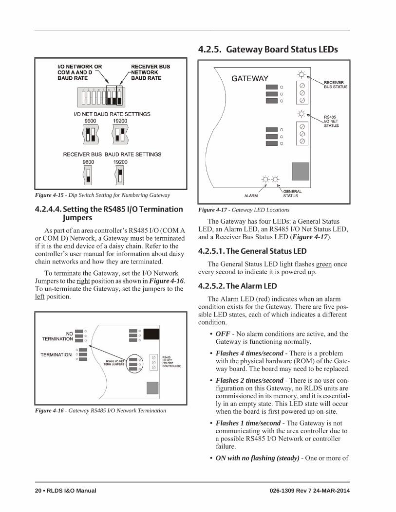
4.2.4.3. Setting the Baud Rate Dip Switches
Dip switches 6 and 7 control the baud rate at which the Gateway communicates with the site controller on the RS485 Network. These switches must be set to the same baud rate setting as the E2, Einstein, or RE-FLECS (usually 9600 baud). All Gateways and RLDS units on the network must have the same baud rate dip switch setting.
Dip switch 8 must be set to the ON position for REFLECS controller mode and OFF for E2, Einstein controller mode.
Baud rate for the RLDS is set by software, either through the RLDS, or on the Gateway Board via Hand-Held Terminal. It is recommended you use 19200 baud as the MODBUS Network baud rate, as it is the default baud rate used by the RLDS. Set dip switch 5 to OFF.
Figure 4-14 - Gateway Dip Switch Numbering
E2, Einstein, and REFLECS Controllers (The RLDS Gateway Board) Connecting Communication Devices • 19
4.2.4.4. Setting the RS485 I/O Termination Jumpers
As part of an area controller’s RS485 I/O (COM A or COM D) Network, a Gateway must be terminated if it is the end device of a daisy chain. Refer to the controller’s user manual for information about daisy chain networks and how they are terminated.
To terminate the Gateway, set the I/O Network Jumpers to the right position as shown in Figure 4-16. To un-terminate the Gateway, set the jumpers to the left position.
4.2.5. Gateway Board Status LEDs
The Gateway has four LEDs: a General Status LED, an Alarm LED, an RS485 I/O Net Status LED, and a Receiver Bus Status LED (Figure 4-17).
4.2.5.1. The General Status LED
The General Status LED light flashes green once every second to indicate it is powered up.
4.2.5.2. The Alarm LED
The Alarm LED (red) indicates when an alarm condition exists for the Gateway. There are five pos-sible LED states, each of which indicates a different condition.
• OFF - No alarm conditions are active, and the Gateway is functioning normally.
• Flashes 4 times/second - There is a problem with the physical hardware (ROM) of the Gate-way board. The board may need to be replaced.
• Flashes 2 times/second - There is no user con-figuration on this Gateway, no RLDS units are commissioned in its memory, and it is essential-ly in an empty state. This LED state will occur when the board is first powered up on-site.
• Flashes 1 time/second - The Gateway is not communicating with the area controller due to a possible RS485 I/O Network or controller failure.
• ON with no flashing (steady) - One or more of
Figure 4-15 - Dip Switch Setting for Numbering Gateway
Figure 4-16 - Gateway RS485 I/O Network Termination
Figure 4-17 - Gateway LED Locations
20 • RLDS I&O Manual 026-1309 Rev 7 24-MAR-2014

the RLDS units is offline. If all are offline, check the wiring. If just one is offline, check the RLDS controller.
4.2.5.3. RS485 I/O Network Status LED
The RS485 I/O Network Status LED flashes or-ange to indicate traffic on the I/O Network (between the Gateway and the site controller). If this light does not come on at all and the Alarm LED is flashing once per second, there is a problem with the RS485 I/O Network or the area controller.
4.2.5.4. Receiver Bus Network Status LED
The Receiver Bus Network Status LED blinks or-ange each time the RLDS Gateway sends a message on MODBUS. However, when the Gateway receives a message from the RLDS units, the LED will flash brightly for 1/2 second.
If the Gateway has RLDS configurations in mem-ory and is communicating properly, you should see this LED flash brightly several times within the course of a few minutes.
E2, Einstein, and REFLECS Controllers (The RLDS Gateway Board) Connecting Communication Devices • 21

5 RLDS - Connecting External Alarms
5.1. OverviewEach RLDS includes four (4) Form C, SPDT re-
lays. The contacts are rated .5A at 250 VAC and 1.0A at 30 VAC. These relays are used for the connection of external alarm devices. The relays are factory-as-signed to the following conditions:
Relay #1 LeakRelay #2 SpillRelay #3 EvacuateRelay #4 Fault
5.2. ConnectionUse the AC conduit or any of the remaining ser-
vice knockouts to gain cable access to the interior of the monitor. Locate the relay connector (Figure 3-9) and remove it from the circuit board.
1. Secure the leads to the connector orienting them as shown in Figure 5-1. Wire the leads to either the N.C. or N.O. terminals of each relay, depending on whether you want the relay to be CLOSED or OPEN when de-energized.
2. When you are through securing the connec-tions, carefully plug the connector back onto the circuit board.
The relay contacts are rated .5 A at 250 VAC.Latching / Non-Latching - refer to Section 7.7.,
Alarm Acknowledge (Ack) - Mode to select Alarm Ack Mode.
Alarm power source - power for the alarm devices connected to the relay contacts may be supplied from the Auxiliary AC Power Out Connector (Figure 3-8).
3. Jumper the Neutral of the input power connec-tor to the Common on the relay block.
4. Connect one end of strobe or horn to the NO of whichever level of alarm is appropriate for ap-plication.
5. The other end of strobe or horn is connected to the Line of the input power connector (5 A maximum).
Figure 5-1 - RLDS Relay Connector
NOTE: Each relay may be connected as nor-mally open (NO), or normally closed (NC).
Figure 5-2 - RLDS Relay 1 and 2 Wiring
22 • RLDS I&O Manual 026-1309 Rev 7 24-MAR-2014

6 RLDS Hardware Specifications
Hardware SpecificationsProduct Type Multiple refrigerant gases and multiple area monitoring system for low level
continuous monitoring of CFC, HCFC, and HFC refrigerant gases used in most commercial refrigeration systems. System design supports compliance to the refrigerant monitoring requirements of ANS/BSR ASHRE 15-2007 and ASHRAE Safety Code 34-2007.
Coverage 4-point standard, expandable to 16 points in 4-point incrementsDetector Type Infrared Non-DispersiveGas Library:CFC:
HFC:
HCFC:
HALON:
Other:
R-11, R-12, R-113, R-114, R-502, HFP
R-404a (HP62), R-407a, R-407c (AC9000), R-134a, R-410a (AZ20), R-507 (AZ50), R-508b (SUVA95), R236FA, R125, R245Fa, R422d, R427a
R-22, R-123, R-124, R-500, R-503, R-401a (MP39), R-402a (HP80), R-402b (HP81), R-408a, R-409a, R-23, R-21, R227
H1301, H2402, H1211
FA188, FC72, N1230, HFO1234YF, R424A, R426A, R427A, R427a, R438A
Sensitivity All gases 1 PPMMeasuring Range All gases 0 to 10,000 PPMAccuracy ±1PPM ±10% of reading from 0-1000 PPM (R11, R22, and R113 ±10 ppm
±15% of reading 0-1000 ppm)Front Panel 3 Indicator lights:
• Green = Monitor is powered on. LED glows during normal operation; flashes when unit is in warm-up mode• Red = Alarm. LED flashes when any point has exceeded the alarm setting• Yellow = Fault. LED flashes when there is a system fault
Size/Weight 12.23”H x 13.7”W x 4.96”D (31.06 cm x 34.80 cm x 12.60 cm) / 15 lbs.
Temperature Drift ±0.3% of reading per degrees CSampling Mode Automatic or manual (hold)Re-Zero Auto or on zone changeResponse Time 5 to 315 seconds – depending on air line length and number of zonesSystem Noise Less than 40dB(A) @ 10 feet (3 meters)Monitoring Distance 1200 ft. (365 meters) maximum for combined length of sample + exhaust tub-
ing (each zone)Conditioned Signal Dual optional 4-20mAdc isolated outputs. Channel 1 = zone area,
Channel 2 = PPM
Table 6-1 - RLDS Specifications
Connection RLDS Hardware Specifications • 23
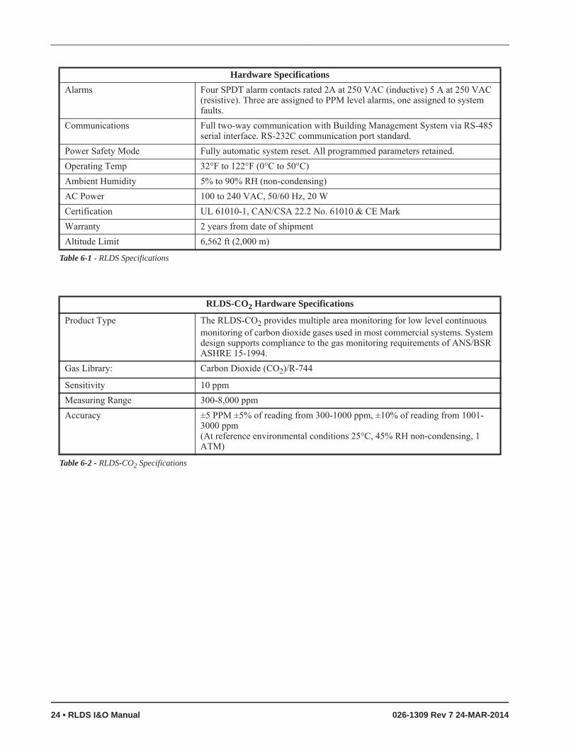
Alarms Four SPDT alarm contacts rated 2A at 250 VAC (inductive) 5 A at 250 VAC (resistive). Three are assigned to PPM level alarms, one assigned to system faults.
Communications Full two-way communication with Building Management System via RS-485 serial interface. RS-232C communication port standard.
Power Safety Mode Fully automatic system reset. All programmed parameters retained.Operating Temp 32°F to 122°F (0°C to 50°C)Ambient Humidity 5% to 90% RH (non-condensing)AC Power 100 to 240 VAC, 50/60 Hz, 20 WCertification UL 61010-1, CAN/CSA 22.2 No. 61010 & CE MarkWarranty 2 years from date of shipmentAltitude Limit 6,562 ft (2,000 m)
RLDS-CO2 Hardware Specifications
Product Type The RLDS-CO2 provides multiple area monitoring for low level continuous monitoring of carbon dioxide gases used in most commercial systems. System design supports compliance to the gas monitoring requirements of ANS/BSR ASHRE 15-1994.
Gas Library: Carbon Dioxide (CO2)/R-744
Sensitivity 10 ppm Measuring Range 300-8,000 ppm Accuracy ±5 PPM ±5% of reading from 300-1000 ppm, ±10% of reading from 1001-
3000 ppm (At reference environmental conditions 25°C, 45% RH non-condensing, 1 ATM)
Table 6-2 - RLDS-CO2 Specifications
Hardware Specifications
Table 6-1 - RLDS Specifications
24 • RLDS I&O Manual 026-1309 Rev 7 24-MAR-2014
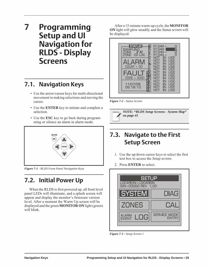
7 Programming Setup and UI Navigation for RLDS - Display Screens
7.1. Navigation Keys• Use the arrow/cursor keys for multi-directional
movement in making selections and moving the cursor.
• Use the ENTER key to initiate and complete a selection.
• Use the ESC key to go back during program-ming or silence an alarm in alarm mode.
7.2. Initial Power UpWhen the RLDS is first powered up, all front level
panel LEDs will illuminate, and a splash screen will appear and display the monitor’s firmware version level. After a moment the Warm Up screen will be displayed and the green MONITOR ON light (green) will blink.
After a 15-minute warm-up cycle, the MONITOR ON light will glow steadily and the Status screen will be displayed:
7.3. Navigate to the First Setup Screen
1. Use the up/down cursor keys to select the first text box to access the Setup screen.
2. Press ENTER to select.Figure 7-1 - RLDS Front Panel Navigation Keys
Figure 7-2 - Status Screen
NOTE: “RLDS Setup Screens - System Map” on page 41
Figure 7-3 - Setup Screen 1
Navigation Keys Programming Setup and UI Navigation for RLDS - Display Screens • 25

7.4. Navigate to the Second Setup Screen
1. From RLDS System Setup screen 1 select the SYSTEM option to go to System Setup screen 2.
2. Press the ESC key to return to the System Setup screen 1.
7.5. LocationThis is the name you assign to the RLDS to iden-
tify its location. It may have up to 12 alphanumeric characters.
1. Press the ENTER key to adjust the setting.2. Use the left/right cursor keys to move across
the entry field and the up/down cursor keys to modify the individual characters.
3. Press ENTER to accept the new entry or ESC to revert to the previous setting.
7.6. Number of Zones Installed
Number of Zones Installed is the number of zones from 1 to 16 connected to the instrument.
IMPORTANT: DO NOT change the number of zones to deactivate unused zones. Changing the num-ber of installed zones is only necessary when mani-fold blocks are added or removed. Go to the individual zone that you wish to disable and set its distance to zero.
1. Press the ENTER key to adjust the number.2. Use the up/down cursor keys to modify the
number. Press ENTER to accept the new num-ber or ESC to revert to the previous setting.
7.7. Alarm Acknowledge (Ack) - Mode
This function programs the relays in the RLDS unit for latching or non-latching operation.
1. Press the ENTER key to adjust the setting.2. Use the up/down cursor keys to toggle between
settings.
AUTO - Non-latching (Alarm relay will automat-ically de-energize when the gas level drops below its alarm point).
MANUAL - Latching (Alarm relay remains ener-gized, and will not release until the alarm condition has been manually acknowledged). Refer to Section 8.6.4., Acknowledging Alarms.
3. Press ENTER to accept the new entry or ESC to revert to the previous setting.
7.8. Audible AlarmThis parameter selects the function of the RLDS
unit’s internal audible alarm device.1. Press the ENTER key to adjust the setting.2. Use the up/down cursor keys to select unused,
monitor on, evacuate, spill, leak, fault, or alarm.
3. Press ENTER to accept the new entry or select ESC to revert to the previous setting.
Figure 7-4 - Setup Screen 2
NOTE: The RLDS auto setting detects the number of zones present on power-up. Do not plug any zones. The number detected on pow-er-up is the default value for this parameter.
26 • RLDS I&O Manual 026-1309 Rev 7 24-MAR-2014

7.9. Zone Hold ModeA zone can be placed on hold and continuously
monitored for a length of time determined by the Zone Hold Time value. To place a zone on hold:
1. Select the zone at the top level screen.2. Press and hold down the ENTER key until the
unit beeps. The word HOLDING will appear in the status box.
3. While in the hold mode, further investigation of the zone's status can be made by navigating to that zone’s Setup Screen 1.
4. To release the zone from the Hold Mode, press and hold down the ENTER key until the unit beeps and the screen display returns to normal.
7.10. Zone Hold TimeSets the length of time a zone will be monitored
when the Zone Hold feature is activated. The default is 15 minutes. The range is 1 to 999 minutes.
1. Press the ENTER key to adjust this setting.2. Use the left/right cursor keys to move across
the entry field and the up/down cursor keys to modify the individual numbers.
3. Press ENTER to accept the new entry or ESC to revert to the previous setting.
7.11. Detection LimitDetection Limit is a squelch setting that instructs
the instrument to interpret PPM readings below the designated level as 0. The range is 1 to 99 PPM.
1. Press the ENTER key to adjust the setting.2. Use the up/down cursor keys to modify the set-
ting.3. Press ENTER to accept the new entry or select
ESC to revert to the previous setting.
7.12. Loop2 FactorLoop2 Factor sets the PPM scale factor for current
loop number 2. To calculate the current output, multi-ply the scale factor by the PPM and add four (4). For example, at the default scale factor of 0.016, a mea-surement of 100 PPM would generate a current output of 5.6 mAdc. The current output cannot exceed the 20 mAdc capacity of the interface.
1. Press the ENTER key to adjust the setting.2. Use the left/right cursor keys to move across
the entry field and the up/down cursor keys to modify the individual characters.
3. Press ENTER to accept the new entry or select ESC to revert to the previous setting.
7.13. Re-Zero ModeThis parameter defines the frequency at which the
instrument re-zeros the optical sensor.1. Press the ENTER key to adjust the setting.2. Use the up/down cursor keys to toggle between
settings. AUTO - sets the instrument to re-zero every 10
minutes.ZONE CHANGE - sets the instrument to re-zero
at each zone change. This is the most accurate setting, but increases the time interval between measurement cycles.
3. Press ENTER to accept the new entry or ESC to revert to the previous setting.
Zone Hold Mode Programming Setup and UI Navigation for RLDS - Display Screens • 27

7.14. Navigating to the Third Setup Screen
From the second System Setup screen, select the MORE option to go to the System Setup screen 3. Se-lect the BACK option to return to the System Setup screen 2.
7.15. Service Timeout
Displayed in Service Mode, Service Timeout sets the length of time the Service Mode is in effect and stops the monitor for up to 300 minutes (5 hrs) to al-low for servicing the unit.
1. Press the ENTER key to adjust the setting.2. Use the left/right cursor keys to move across
the entry field and the up/down cursor keys to modify the individual numbers.
3. Press ENTER to accept the new entry or ESC to revert to the previous setting.
7.16. Node AddressEach RLDS on the network must have a distinct
node address. The node address may be set from 1 to 64.
1. Press the ENTER key to adjust the setting.2. Use the left/right cursor keys to move across
the entry field and the up/down cursor keys to modify the individual numbers.
3. Press ENTER to accept the new entry or ESC to revert to the previous setting.
7.17. PasswordThis field is used to define a system password. The
default setting is 000, which provides no password protection.
1. Press the ENTER key to adjust the password.2. Use the left/right cursor keys to move across
the entry field and the up/down cursor keys to modify the individual alphanumeric characters.
3. Press ENTER to accept the new password or ESC to revert to the previous setting.
7.18. Accessing Additional Features
Several additional features can be viewed on the System Setup screen 3 when the RLDS is placed in Service Mode (refer to Section 8.11., Service Mode). While in service mode, the user can identify the mod-el number, set digipot values and sensor temperature, and acquire the temperature coefficient.
Figure 7-5 - Setup Screen 3
NOTE: The RS485 BAUD rate text will be re-placed by “Service Timeout” when in Service Mode.
28 • RLDS I&O Manual 026-1309 Rev 7 24-MAR-2014

7.19. DET Digipot
The DIGIPOT function allows a manual and more precise adjustment of the digital potentiometer, which controls the voltage of the IR Detector. The DIGIPOT is auto-tuned at every power up.
1. Press the ENTER key to adjust the setting. Once the option is selected the screen will also display the voltage.
2. Use the up/down cursor key to modify the Di-gipot value.
3. Press ENTER to accept the new entry or ESC to revert to the previous setting.
7.20. Sensor Temperature Coefficient
1. Press the ENTER key to adjust the setting.2. Use the up/down cursor key to modify the tem-
perature value.3. Press ENTER to accept the new entry or ESC
to revert to the previous setting.
7.21. Acquiring Temperature Coefficient (Factory Use Only)
Press the left/right arrow buttons simultaneously to return to the previous screen.
7.22. R DigipotThis option will indicate the electrical parameters
of the infrared emitter.
Figure 7-6 - System Setup Screen 3 - Service Mode
DET Digipot Programming Setup and UI Navigation for RLDS - Display Screens • 29

8 General Operation of RLDS - UI
8.1. Functional OverviewNormally each RLDS will perform measurements
on its active zones sequentially and without user in-put. The total time it takes an RLDS to complete a measurement cycle is directly proportional to the number of active zones and the physical length of the air lines. Monitors linked together on a network oper-ate independently of each other and consequently complete their respective measurement cycles at dif-ferent rates.
8.2. The Zone ScreenFrom the System Setup screen 1 (Figure 7-3),
scroll down and select the ZONES option (or select the desired zone from the Status screen (Figure 7-2).
8.2.1. LocationThis is the name you assign to the RLDS to iden-
tify its location. It may have up to 12 alphanumeric characters.
1. Press the ENTER key to adjust the setting.2. Use the left/right cursor keys to move across
the entry field and the up/down cursor keys to modify the individual characters.
3. Press ENTER to accept the new entry or ESC to revert to the previous setting.
8.2.2. Refrigerant TypeThis displays the kind of refrigerant the RLDS is
detecting.1. Press the ENTER key to adjust the setting.2. Use the left/right cursor keys to select the type
of refrigerant you want the device to detect.3. Press ENTER to accept the new entry or ESC
to revert to the previous setting.
8.2.3. DistanceThis displays the combined length of the sample
tubing plus any tubing on the exhaust port. Total length should not exceed 1200 feet (365 meters).
1. Press the ENTER key to adjust the setting.2. Use the left/right cursor keys to move across
the entry field and the up/down cursor keys to modify the individual characters.
3. Press ENTER to accept the new entry or ESC to revert to the previous setting.
8.2.4. Zone TemperatureThis displays the air temperature at the zone being
sampled.
1. Press the ENTER key to adjust the setting.2. Use the left/right cursor keys to move across
the entry field and the up/down cursor keys to modify the individual characters.
3. Press ENTER to accept the new entry or ESC to revert to the previous setting.
8.2.5. Current Detection ReadingThis reading displays the current PPM STP level
of the selected refrigerant being detected by the de-vice.
Figure 8-1 - Zone Setup Screen 1
30 • RLDS I&O Manual 026-1309 Rev 7 24-MAR-2014

8.2.6. Log IntervalThe RLDS retains a data log of 100 measurements
for each zone. The log interval is the number of min-utes from 1 to 1440 between each log point. This pa-rameter can be changed from Zone Setup screen 1 (Figure 8-1).
The default setting for this parameter is 1440 min-utes (24 hours). If the log interval time is set to 0, then a measurement is recorded in the trend log after every measurement cycle. Therefore, after the trend log is filled, it will contain the last 100 measurement points for a zone. If you want the data logged less frequently, increase this value.
It is important to remember that cycle time is de-pendent on many factors, including the number of zones being monitored, input line length, and the run zeroing mode selected. Before changing this value it may be useful to review the log data first using the Trend screen to determine the nominal cycle time.
8.3. Navigating to the Second Home Screen
Select the MORE option at the bottom right hand side of the screen (Figure 8-1) to continue to the next screen containing more options. This screen displays the peak PPM value in the upper side of the screen.
8.3.1. Leak LevelThis is the concentration level in PPM that will ac-
tivate a leak alarm condition.
1. Press the ENTER key to adjust the value.2. Use the up/down cursor keys to modify the set-
ting.3. Press ENTER to accept the new entry or ESC
to revert to the previous setting.
8.3.2. Spill LevelThis is the concentration level in PPM that will ac-
tivate a spill alarm condition.
1. Press the ENTER key to adjust the value.2. Use the up/down cursor keys to modify the set-
ting.3. Press ENTER to accept the new entry or ESC
to revert to the previous setting.
8.3.3. Evacuation LevelThis is the concentration level in PPM that will ac-
tivate an evacuate alarm condition.
1. Press the ENTER key to adjust the value.2. Use the up/down cursor keys to modify the set-
ting.3. Press ENTER to accept the new entry or ESC
to revert to the previous setting.
8.3.4. Resetting the Peak PPM ValuePressing this key resets the current peak PPM level
stored in memory and displays it at the top of the screen.
Figure 8-2 - Zone Setup Screen 2
NOTE: This value must be less than the spill level.
NOTE: This value must be less than the evac-uate level and greater than the leak level.
NOTE: This value must be greater than the spill level.
Navigating to the Second Home Screen General Operation of RLDS - UI • 31

8.4. Alarm ConditionsWhen an alarm condition is detected anywhere on
the network, the red ALARM LED will glow on the front of the unit. Additionally, an external alarm de-vice may activate and an audible alarm may sound if those features have been enabled (Section 4.2., E2, Einstein, and REFLECS Controllers (The RLDS Gateway Board).
An inverse flashing box indicates an alarm condi-tion in the affected zone.
You can investigate the status of the affected zone further by selecting the ALARM option on the Status screen (Figure 7-2).
8.5. Fault ConditionsIf a system malfunction occurs, the yellow
FAULT LED will glow. Additionally, an external alarm (Section 4.2., E2, Einstein, and REFLECS Con-trollers (The RLDS Gateway Board) device may acti-vate and an audible alarm may sound if those features have been enabled (Section 7.8., Audible Alarm).
8.6. Alarms
8.6.1. Functional OverviewIf the PPM level for any zone exceeds its designat-
ed spill, leak, or evacuate thresholds, an alarm condi-tion will be created. Once the RLDS completes a measurement cycle in the affected zone the alarm condition will be indicated. At that time the red ALARM LED on the RLDS will glow. Additionally, an external alarm device may activate and an audible alarm may sound if those features have been enabled (Section 7.8., Audible Alarm).
The alarm condition may or may not have to be ac-knowledged for the system to return to normal opera-tion.
8.6.2. Responding to AlarmsAn operator can respond to alarms by accessing
the Alarm Summary screen. Navigate to this screen by selecting ALARM on the Status screen 1 (Figure 7-2).
Alarm Summary Screen
The Alarm Summary screen displays a list of all alarm conditions pending across the network. The screen is divided into eight (8) boxes, and each box represents a single alarm. If more than eight (8) alarms are pending, additional pages can be displayed by selecting the MORE option (visible when there are more than eight (8) alarms pending).
Each box displays the zone number, zone name, and the current PPM reading. A flashing box indicates an alarm that has not been acknowledged. A static box represents an alarm that has been acknowledged but has not yet been cleared from the system.
The Alarm Data Log can be reset by pressing a combination of the ENTER and right arrow buttons while viewing the log.
Figure 8-3 - Alarm Summary Screen
32 • RLDS I&O Manual 026-1309 Rev 7 24-MAR-2014

8.6.3. Alarm Detail ScreenThe Alarm Detail screen displays more compre-
hensive information about the nature of the alarm in-cluding:
• Complete location information• Gas type and current concentration (CONC
NOW)• Peak concentration and peak time• Type of alarm, alarm time, and date
This screen provides the following navigation op-tions at the bottom of the display:
• ACK - using the left arrow key, ACK will ac-knowledge the alarm as described in the next section.
• SETUP - using the right arrow key, navigate to the Zone Setup screen 1 (Figure 8-1). This en-ables review of the zone setup parameters and accesses the Trend screen.
Use the ESC button on the RLDS unit to go back to the previous menu.
8.6.4. Acknowledging AlarmsEach pending alarm may require, depending upon
selected alarm mode, acknowledgment before the system returns to normal operation Section 7.7., Alarm Acknowledge (Ack) - Mode. To acknowledge an alarm, navigate to the Alarm Detail screen and se-lect the ACK option as previously described. You will then be returned to the Alarm Summary screen and the box associated with that alarm will no longer
be blinking, indicating that the alarm has been ac-knowledged. Repeat this procedure to acknowledge any remaining alarms.
Alarm Summary Screen (Acknowledge Mode)
Once all the alarms associated with a given RLDS are acknowledged, its red LED will turn off, and any external alarms connected to the RLDS relays will de-activate. Keep in mind that the system will continue to generate new alarms if PPM values above the alarm thresholds are detected.
8.7. System Faults
8.7.1. Functional OverviewIf a system malfunction occurs, the yellow
FAULT LED to glow. Additionally, an external alarm device may activate and an audible alarm may sound if those features have been enabled (Section 7.8., Audible Alarm).
Depending on the nature of the fault, the RLDS may or may not continue to operate normally. Under a non-critical fault condition, the RLDS will continue to measure and log data, but some peripheral func-tions may be compromised. Under a critical fault con-dition, action is required for the RLDS to operate normally.
Various fault conditions are listed and explain what action should be taken to correct the problem in Section 8.7.2.1., Critical Faults.
Figure 8-4 - Alarm Detail ScreenFigure 8-5 - Alarm Summary Screen - Acknowledge Mode
System Faults General Operation of RLDS - UI • 33

8.7.2. Navigating to the Fault ScreenDisplayed on the initial Status screen (Figure 7-2)
is a Fault option. Scroll down with the cursor key and select this option, and the Fault screen will display:
8.7.2.1. Critical Faults
• NO FLOW ON ZONE - Go to the Status screen (Figure 7-2) and select FAULT. This will display a NO FLOW message in each indi-vidual zone affected. Check for a blockage in the air sample line or at the line-end filter. Once the blockage has been cleared, the RLDS will return to normal operation after the zone has been sampled.
• NO FLOW ON PURGE - Check the purge line for a blockage. Verify that the length of the purge line and exhaust line do not exceed 500 feet (152 meters) in length.
• NO FLOW DETECTED - Check for proper pump operation. Examine the hydrophobic fil-ter for contaminants or water on the input side. If the input side is gray, a contaminant is pres-ent and the filter must be replaced. To drain, re-move the tubing from both sides of the filter and tap the tubing on a hard surface to dislodge the contents.
• CLIPPING FAULT - The detector voltage
may be out of tolerance. Refer to the Diagnostic screen (Figure 8-12) for the DET voltage, AVE voltage and ZERO voltage. Contact Technical Support with this information for further in-structions.
• REZERO VOLT TOL - The detector output voltage is out of tolerance. Refer to the Diag-nostic screen (Figure 8-12) and contact Tech-nical Support for assistance.
• TRIGGER FAULT - No trigger from IR source pulser. Contact Technical Support with all information from the Diagnostic screen (Figure 8-12) for further instructions.
8.7.2.2. Non-Critical Faults
• BOX TEMP FAULT - Enclosure's internal temperature is outside normal range (or IR sen-sor has failed). Check the installation to verify that the monitor is not being subjected to ex-treme temperatures. Verify that the ventilation holes are not obstructed. Check the Diagnostic screen (Figure 8-12) for the ZERO tempera-ture, BNCH temperature and BOX tempera-ture. Contact Technical Support with this information for further instructions.
• BENCH TEMP FAULT - Optical bench is outside of normal operating range (or sensor has failed). Check the installation to verify that the monitor is not being subjected to extreme temperatures. Check the Diagnostic screen (Figure 8-12) for the ZERO temperature, BNCH temperature and BOX temperature. Contact Technical Support with this informa-tion for further instructions.
• PRESSURE SENSOR - Manifold pressure is outside normal operating range (or sensor has failed). Check the Diagnostic screen record ALL data (Figure 8-12). Contact Technical Support with this information for further in-structions.
• LOOP FAULT - This would only be displayed if the dual 4-20 mAdc option was installed and one or both current loops are open. Check the wiring to load/monitoring circuit on both 4-20 mA loops.
• CONFIG FAULT - There is an error in the RLDS Setup screen 2 - NUMBER ZONES IN-STALLED field (Figure 7-4). Check that the number of zones installed for each RLDS unit and the number of RLDS units on the network
Figure 8-6 - Fault Screen
NOTE: This can take several minutes since it is dependent upon how many zones there are and their lengths. The RLDS will
clear the fault the next time it polls the affected zone.
34 • RLDS I&O Manual 026-1309 Rev 7 24-MAR-2014

are properly programmed. Check to ensure that the manifold solenoid cable connector in each RLDS unit is securely fastened to its terminal connector. Check for an illegal parameter. If necessary, reset to the factory default settings.
8.7.3. Reset to Factory Default Settings
IMPORTANT: Performing this function ERAS-ES all program parameters, alarms, faults, trends, and log files.
8.7.3.1. Resetting the RLDS
Press and hold down the Factory Default switch inside the RLDS (Figure 3-8):
1. Cycle AC power OFF then ON2. Listen for five beeps3. Release the switchReprogram the RLDS as described in Section 7,
Programming Setup and UI Navigation for RLDS - Display Screens.
8.7.4. Clearing System FaultsIf the fault condition is associated with an RLDS,
the monitor will return to normal operation soon after the problem is corrected. At that time the yellow LED will turn off and any external alarms connected to the monitor's alarm relays will also turn off.
Once the system malfunction has been corrected, it may take some time for the fault condition to clear completely. If the fault is associated with a specific zone, the RLDS must first cycle back to the affected zone before it returns to normal operation. At that time the yellow LED will turn off and any external alarms connected to the monitor's alarm relays will also turn off.
8.7.5. Viewing Fault LogA data log of the last 20 fault conditions is retained
in memory. On the Fault screen (Figure 8-6) select the LOG option to view a display of the Fault Log:
This screen lists potential fault conditions in the left column and displays a check mark indicating which problems were associated with each fault con-dition as represented by the vertical cursor bar. As you move the bar horizontally using the left/right cur-sor keys, the date and time the fault condition was de-tected are displayed in the upper right hand corner of the display window.
Anytime the fault status changes, there is an entry in the fault log, both when the fault occurs and when it is cleared.
The Fault Log can be reset by pressing a combina-tion of the ENTER and right arrow buttons while viewing the log.
Figure 8-7 - Fault Log Screen
System Faults General Operation of RLDS - UI • 35

8.7.6. Viewing Flow LogOn the Fault Log screen, press ENTER (as shown
in Figure 8-7) to access the Flow Log screen. The Flow Log displays the last 20 flow events for all zones and the purge port.
This screen lists the zones in the left column and displays flow data. Use the up/down buttons to scroll through the zones and the left/right to scroll through the log data. As you move the bar horizontally, the date and time of the condition are displayed in the up-per right hand corner.
The Flow Log can be reset by pressing a combina-tion of the ENTER and right arrow buttons while viewing the log.
8.8. The Trend Screen
8.8.1. Navigating to the Trend Screen
From the Zone screen (Figure 8-1), select the Trend option on the bottom left side. This will open the Trend screen:
The trend graph opens with the cursor located over the most recent data point. Use the left/right cursor keys to move the cursor to different data points. Hold-ing a key down will cause the cursor to move rapidly across the screen. As you move the cursor position, the date and time of that reading, along with the PPM value, are displayed at the top of the screen above the graph. The trend graph is automatically scaled to ac-commodate the largest PPM value displayed. The ZOOM OUT and ZOOM IN options allow you to ad-just the vertical scale of the graph.
The trend data is stored on a first-in, first-out basis. After 100 trend values have been stored, the 101st value will replace the first value stored; therefore, in normal operation, when entering trend mode the cur-sor will be located at the most recent data point. The data points to the left of the initial cursor location will be the next most recent. The data point to the right will be the oldest data point in the buffer and will be overwritten by the next data point.
The Trend Data Log can be reset by pressing a combination of the ENTER and right arrow buttons while viewing the log.
When finished, press the ESC key to revert to the previous screen.
8.9. The Calibration Screen
8.9.1. OverviewThe Calibration Screen is used to adjust the cali-
bration factor for each refrigerant gas. It is also used to program the instrument for new gases.
Figure 8-8 - Flow Log Screen
Figure 8-9 - Trend Screen
36 • RLDS I&O Manual 026-1309 Rev 7 24-MAR-2014
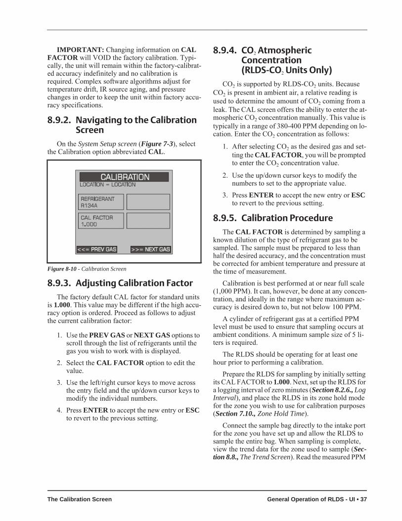
IMPORTANT: Changing information on CAL FACTOR will VOID the factory calibration. Typi-cally, the unit will remain within the factory-calibrat-ed accuracy indefinitely and no calibration is required. Complex software algorithms adjust for temperature drift, IR source aging, and pressure changes in order to keep the unit within factory accu-racy specifications.
8.9.2. Navigating to the Calibration Screen
On the System Setup screen (Figure 7-3), select the Calibration option abbreviated CAL.
8.9.3. Adjusting Calibration FactorThe factory default CAL factor for standard units
is 1.000. This value may be different if the high accu-racy option is ordered. Proceed as follows to adjust the current calibration factor:
1. Use the PREV GAS or NEXT GAS options to scroll through the list of refrigerants until the gas you wish to work with is displayed.
2. Select the CAL FACTOR option to edit the value.
3. Use the left/right cursor keys to move across the entry field and the up/down cursor keys to modify the individual numbers.
4. Press ENTER to accept the new entry or ESC to revert to the previous setting.
8.9.4. CO2 Atmospheric Concentration (RLDS-CO2 Units Only)
CO2 is supported by RLDS-CO2 units. Because CO2 is present in ambient air, a relative reading is used to determine the amount of CO2 coming from a leak. The CAL screen offers the ability to enter the at-mospheric CO2 concentration manually. This value is typically in a range of 380-400 PPM depending on lo-cation. Enter the CO2 concentration as follows:
1. After selecting CO2 as the desired gas and set-ting the CAL FACTOR, you will be prompted to enter the CO2 concentration value.
2. Use the up/down cursor keys to modify the numbers to set to the appropriate value.
3. Press ENTER to accept the new entry or ESC to revert to the previous setting.
8.9.5. Calibration ProcedureThe CAL FACTOR is determined by sampling a
known dilution of the type of refrigerant gas to be sampled. The sample must be prepared to less than half the desired accuracy, and the concentration must be corrected for ambient temperature and pressure at the time of measurement.
Calibration is best performed at or near full scale (1,000 PPM). It can, however, be done at any concen-tration, and ideally in the range where maximum ac-curacy is desired down to, but not below 100 PPM.
A cylinder of refrigerant gas at a certified PPM level must be used to ensure that sampling occurs at ambient conditions. A minimum sample size of 5 li-ters is required.
The RLDS should be operating for at least one hour prior to performing a calibration.
Prepare the RLDS for sampling by initially setting its CAL FACTOR to 1.000. Next, set up the RLDS for a logging interval of zero minutes (Section 8.2.6., Log Interval), and place the RLDS in its zone hold mode for the zone you wish to use for calibration purposes (Section 7.10., Zone Hold Time).
Connect the sample bag directly to the intake port for the zone you have set up and allow the RLDS to sample the entire bag. When sampling is complete, view the trend data for the zone used to sample (Sec-tion 8.8., The Trend Screen). Read the measured PPM
Figure 8-10 - Calibration Screen
The Calibration Screen General Operation of RLDS - UI • 37

by placing the cursor on the spikes cause by the sam-ple. If the bag was large enough for multiple samples, average the most stable ones.
The new CAL factor is computed by dividing the known gas value by the measured value. Typically this value will be between 0.95 and 1.05. This value is stored in non-volatile memory.
8.9.6. Programming New GasesAs new refrigerants come into use, the RLDS al-
lows the addition of these new gases to its on-board refrigerant gas library. At the end of the gas library list is an option labeled CUSTOM for adding new gases. From the Calibration screen use the left/right arrows to select CUSTOM from the list of refrigerants. Next, press ENTER, and use the up/down arrow keys to en-ter the calibration factor.
The selection of the matching gas and CAL factor is performed by analyzing the new refrigerant. Once the matching gas is determined, field calibration is possible by using the same procedure as for other re-frigerants. When the new gas entry is complete, sim-ply set up the appropriate zone for CUSTOM.
Program the instrument for a new gas as follows:
1. From the Calibration screen, use the PREV GAS or NEXT GAS options to scroll through the list of available choices until the CUSTOM option is displayed.
2. Select the CUSTOM option. Press ENTER to accept the new entry or ESC to revert to the previous setting.
3. Enter the new CAL Factor as received from Emerson Retail Solutions.
Figure 8-11 - Custom Gas Screen
38 • RLDS I&O Manual 026-1309 Rev 7 24-MAR-2014
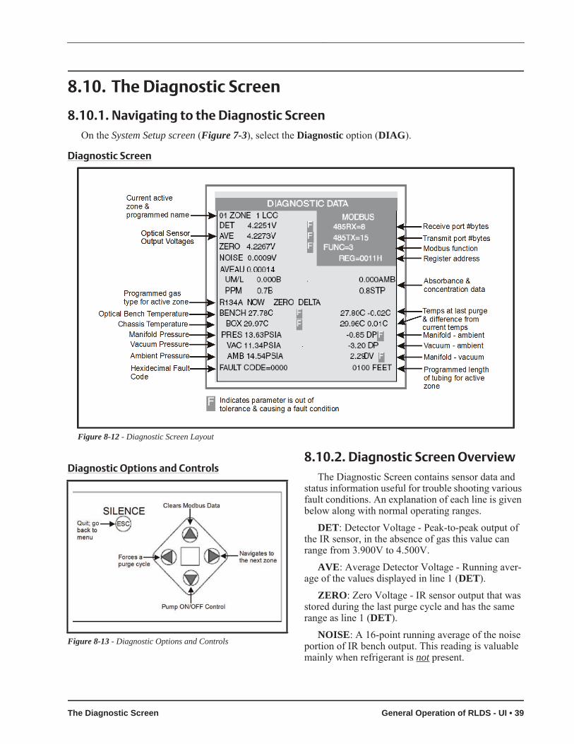
8.10. The Diagnostic Screen
8.10.1. Navigating to the Diagnostic ScreenOn the System Setup screen (Figure 7-3), select the Diagnostic option (DIAG).
Diagnostic Screen
Diagnostic Options and Controls8.10.2. Diagnostic Screen Overview
The Diagnostic Screen contains sensor data and status information useful for trouble shooting various fault conditions. An explanation of each line is given below along with normal operating ranges.
DET: Detector Voltage - Peak-to-peak output of the IR sensor, in the absence of gas this value can range from 3.900V to 4.500V.
AVE: Average Detector Voltage - Running aver-age of the values displayed in line 1 (DET).
ZERO: Zero Voltage - IR sensor output that was stored during the last purge cycle and has the same range as line 1 (DET).
NOISE: A 16-point running average of the noise portion of IR bench output. This reading is valuable mainly when refrigerant is not present.
Figure 8-12 - Diagnostic Screen Layout
Figure 8-13 - Diagnostic Options and Controls
The Diagnostic Screen General Operation of RLDS - UI • 39

AVEAU: Average Absorbency - Optical absor-bency computed from the Average Detector Voltage and Zero Voltage. In the absence of refrigerant the ab-sorbency is 0.000AU. When sampling refrigerants, its value varies proportionally with the refrigerant con-centration.
UM/L: uMoles/L - Absolute concentration in mi-cro-moles per liter of refrigerant based on NOISE and the internal calibration. There are two figures dis-played: the first (annotated by a B) is the actual mea-surement at the IR bench. The second is the calculated value corrected to ambient conditions (temperature + pressure).
PPM: Parts Per Million is the volume concentra-tion referenced to standard temperature and pressure and is computed from the Average Absorbency, Zero Temperature, and Ambient Pressure. There are two figures displayed. The first (annotated by a B) is the actual PPM at the IR bench. The second is a PPM reading normalized to standard temperature and pres-sure.
ZERO: Zero Temperature - Displays the sensor and enclosure temperature measured and stored during the last purge cycle in degrees C.
BENCH: Bench Temperature - Current IR sensor temperature in degrees C as well as the raw voltage coming from the temperature sensor. This value can range from ambient to ambient +15 degrees C.
BOX: Box Temperature - Current internal enclo-sure temperature along with the raw voltage from the temperature sensor, and has the same range as Bench Temperature.
PRESS: Pressure - Current absolute manifold pressure in PSIA along with the output voltage of the pressure sensor. This value should always be 0.2 to 1.0 PSIA below Ambient Pressure (AMB).
VAC: Vacuum - The vacuum pressure is mea-sured every purge cycle by closing all sample valves. Its value is typically 2.5 to 4.0 PSIA below Ambient Pressure (AMB).
AMB: Ambient - Ambient pressure is measured every purge cycle with the sample pump off and the manifold open. Its value is weather and altitude de-pendent and can range from 10.0 to 15.5 PSIA.
FAULT CODE: For fault code information, see the fault code list (Table 8-3 on page 45).
XXXX FEET: Programmed length of tubing for an active zone.
8.11. Service ModeThe Service Mode option is located on the System
Setup screen in the bottom right corner.When activated, Service Mode will disable the
RLDS unit for a specified length of time. The default is 60 minutes. This time interval can be changed as described in Section 7.15., Service Timeout.
IMPORTANT: Note that while in the Service Mode no measurements are made, nor are any alarms activated.
Access the Service Mode options from the initial Status screen. Press the SERVICE MODE ENTRY option twice within 3 seconds.
To exit the Service Mode, again press the SER-VICE MODE ENTRY option twice within 3 sec-onds.
40 • RLDS I&O Manual 026-1309 Rev 7 24-MAR-2014

RLDS Setup Screens - System Map
Service Mode General Operation of RLDS - UI • 41

RLDS Alarm and Fault Screens - System Map
42 • RLDS I&O Manual 026-1309 Rev 7 24-MAR-2014

Recommended Gas Alarm Settings
Refrigerant Leak PPM Spill PPM Evacuate PPMR11 100 300 500R12 100 300 500R22 100 300 500R23 100 300 500R113 100 300 500R114 100 300 500R123 25 35 35R124 100 300 500
R134A 100 300 500R401A 100 300 500R402A 100 300 500R402B 100 300 500R404A 100 300 500R407A 100 300 500R407C 100 300 500R409A 100 300 500R410A 100 300 500R500 100 300 500R502 100 300 500R503 100 300 500R507 100 300 500R50B 100 300 500H1301 100 300 500R408A 100 300 500FA188 100 300 500
R236FA 100 300 500N1230 100 300 500R227 100 300 500HFP 100 300 500FC72 100 300 500R21 100 300 500R125 100 300 500
H1211 100 300 500H2402 100 300 500Custom 100 300 500
R245FA Supported in Gate-way version 1.2 and above
100 300 500
Table 8-1 - Recommended Alarm Settings and Gas Enumeration
Service Mode General Operation of RLDS - UI • 43
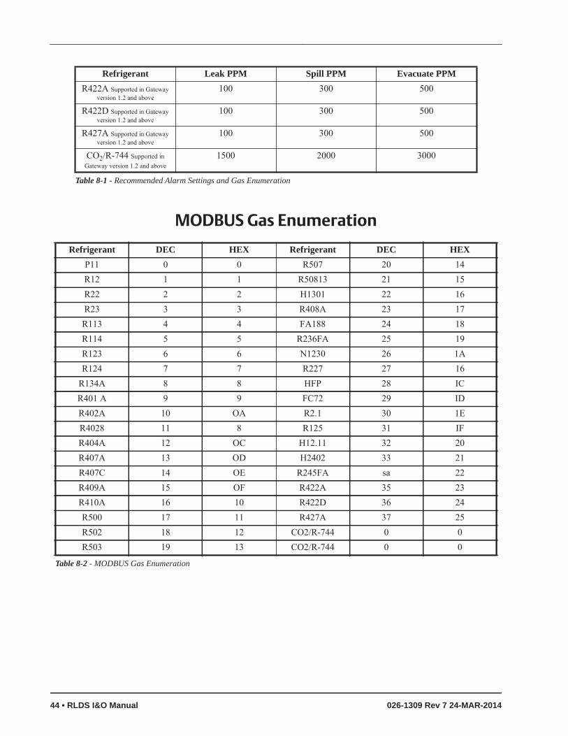
MODBUS Gas Enumeration
R422A Supported in Gateway version 1.2 and above
100 300 500
R422D Supported in Gateway version 1.2 and above
100 300 500
R427A Supported in Gateway version 1.2 and above
100 300 500
CO2/R-744 Supported in Gateway version 1.2 and above
1500 2000 3000
Refrigerant Leak PPM Spill PPM Evacuate PPM
Table 8-1 - Recommended Alarm Settings and Gas Enumeration
Refrigerant DEC HEX Refrigerant DEC HEXP11 0 0 R507 20 14R12 1 1 R50813 21 15R22 2 2 H1301 22 16R23 3 3 R408A 23 17R113 4 4 FA188 24 18R114 5 5 R236FA 25 19R123 6 6 N1230 26 1AR124 7 7 R227 27 16
R134A 8 8 HFP 28 ICR401 A 9 9 FC72 29 IDR402A 10 OA R2.1 30 1ER4028 11 8 R125 31 IFR404A 12 OC H12.11 32 20R407A 13 OD H2402 33 21R407C 14 OE R245FA sa 22R409A 15 OF R422A 35 23R410A 16 10 R422D 36 24R500 17 11 R427A 37 25R502 18 12 CO2/R-744 0 0R503 19 13 CO2/R-744 0 0
Table 8-2 - MODBUS Gas Enumeration
44 • RLDS I&O Manual 026-1309 Rev 7 24-MAR-2014

Fault Codes
BIT Fault Type Code Description15 CLIPPING FAULT 0x8000 Sensor output voltage too high14 ZERO RANGE FAULT 0x4000 Sensor output voltage outside limits during purge13 OVER RANGE FAULT 0x2000 Gas concentration above measurable range12 PURGE FLOW FAULT 0x1000 No flow detected during purge cycle11 ZONE FLOW FAULT 0x0800 No flow detected during sample cycle10 A2D FAULT 0x0400 Analog to digital converter not working9 GAIN SET FAULT 0x0200 Digipot gain setting out of normal range8 ZERO FILTER FAULT 0x0100 Charcoal filter (if used) needs replacement7 CONFIG FAULT 0x0080 No zones are enabled6 UNUSED FAULT 2 0x0040 Not used5 UNUSED FAULT 1 0x0020 Not used4 LOOP FAULT 0x0010 Current loop is open3 RS485 FAULT 0x0008 Communication error2 MANIFOLD P FAULT 0x0004 Pressure sensor readings are out of range1 BENCH T FAULT 0x0002 Sensor temperature is out of range0 BOX T FAULT 0x0001 Chassis temperature is out of range
Table 8-3 - Fault Codes
Service Mode General Operation of RLDS - UI • 45


9 Quick Setups for Hand-Held Terminal (HHT)
Summaries of Zone Setup and Date/Time Setup have been included here for your convenience. For more detailed information about these setup proce-dures, please refer to their respective sections in this manual.
9.1. Time/Date SetupTime and date is set from the CONFIG OPTION
screen.
1. From the Home screen (F1), press the down ar-row key three (3) times to display the OPTION screen:
2. Press the right arrow key and select 3.3. Press the down arrow key twice to display the
CONFIG OPTION screen:
4. Press the right arrow key and select 2.5. Press the down arrow key twice to open the
TIME/DATE screen:
A change in the Time/Date on any one of the RLDS controllers changes ALL of the RLDS control-lers on the network.
6. Press the right arrow key to edit the fields. The right and down arrow keys scroll downward through the list, while the left or up arrow keys will backspace the arrow so you may go back to change a field.
7. Press the up arrow key to scroll back up to the CONFIG OPTION screen to calibrate gases. Your changes are saved and the data is written when you scroll back up to the CONFIG OP-TION screen.
9.2. Zone Setup
9.2.1. General Configuration 1 Screen
1. From the CONFIG OPTION screen, press the right arrow key and then press the 1 key for RLDS CTRL.
2. Press the down arrow key twice to display the General Configuration 1 screen:
3. Press the down arrow key to display the Gener-al Configuration 2 screen:
NOTE: There is a short interval after the mes-sage WAITING ON READ FROM RLDS.
OPTION: 1 1 = RLDS STATUS 2 = RLDS FAULTS 3 = RLDS CONFIG
CONFIG OPTION: 1 1 = RLDS CTRL 2 = TIME/DATE 3 = CALIB GASES
1-DATE: xx-xx-xx1-TIME: xx:xx:xx
NOTE: For TIME, enter military time only.
Ux: ENABLED:DISABLEDUx- ZONES: 8 Ux- MODEL: 300Ux- REV : 1.12
NOTE: x is the RLDS currently being ac-cessed.
Time/Date Setup Quick Setups for Hand-Held Terminal (HHT) • 47

9.2.2. General Configuration 2 Screen
4. Press the right arrow key to activate the U1 field so you can change the name of the con-troller. Use the right and left arrow keys to move across the field to select each letter, and remember to use the “.” and “—” keys to toggle letters.
5. Press the down arrow key to move from the U1 field to the BUZZER field. The default for this field is set to NONE. Use the “.” and “—” keys to scroll through the choices: NONE, ALARM, FAULT, LEAK, SPILL, EVAC, or MN OFF (monitor is offline and is no lon-ger monitoring the refrigerant lines).
6. Press the down arrow key to move from the BUZZER field to the AL ACK field. The de-fault for this field is set to MANUAL, but it is recommended the setting be changed to AUTO so the zone can automatically reset itself after the condition clears.
7. Press the down arrow key to scroll you to the next screen:
9.2.3. Zone Config Screen 1The Zone Configuration Screen 1 is used to con-
figure an individual zone:
• ZONE (name) can be 1-12 characters and is an alphanumeric representation of the location of the zone.
• REFRIG (refrigerant) is the gas being detected in that zone. The default is set to R134a and must be changed using the “.” and “—” keys to select the appropriate refrigerant.
• LENGTH (tubing length) is the total tubing length for that zone. Length is 500 feet for an active zone and 0 (zero) for a deactivated zone. The tubing range is 0-500 feet.
8. Press the right arrow key to activate the ZONE (name of zone) field so you can change the name of the zone. Use the right and left arrow keys to move across the field to select each let-ter, and remember to use the “.” and “—” keys to toggle letters.
9. Press the down arrow key to move from the ZONE field to the REFRIG field. The default for this field is set to R134a, but use the “.” and “—” keys to scroll through the refrigerant choices.
10.Press the down arrow key to move from the REFRIG field to the LENGTH field. Enter the length of tubing for the zone.
11.Press the down arrow key to display the Zone Config Screen 2:
U1: NAME OF CONTROLLER 1 - BUZZER: NONE1 - AL ACK: MANUAL
NOTE: The “blank” line is used to provide a cursor so the user knows which character they are editing. The “.” and “—” keys are used to scroll an individual character selection or nu-
meric numbers can be entered directly.
NOTE: In MANUAL mode an alarm will not clear until it is acknowledged and the alarm condition is no longer active. Even if the alarm is no longer active and it has been acknowl-
edged, it is not cleared until the next time that zone is read. On a 16-zone device this will take at least four (4) minutes.
01: ZONE 01 LOC 01 - REFRIG: 01 - LENGTH:
NOTE: The “blank” line is used to provide a cursor so the user knows which character they are editing. The “.” and “—” keys are used to scroll an individual character selection or nu-
meric numbers can be entered directly.
NOTE: Set LENGTH to 0 (zero) for any zones not being used.
48 • RLDS I&O Manual 026-1309 Rev 7 24-MAR-2014
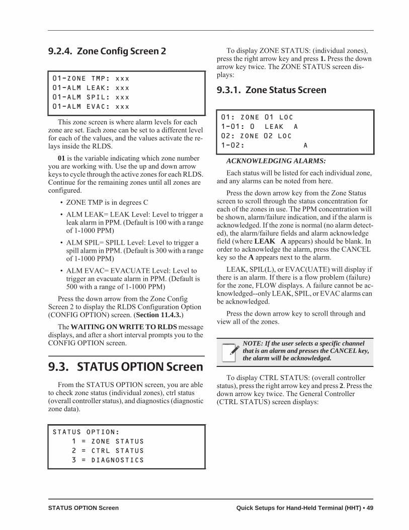
9.2.4. Zone Config Screen 2
This zone screen is where alarm levels for each zone are set. Each zone can be set to a different level for each of the values, and the values activate the re-lays inside the RLDS.
01 is the variable indicating which zone number you are working with. Use the up and down arrow keys to cycle through the active zones for each RLDS. Continue for the remaining zones until all zones are configured.
• ZONE TMP is in degrees C• ALM LEAK= LEAK Level: Level to trigger a
leak alarm in PPM. (Default is 100 with a range of 1-1000 PPM)
• ALM SPIL= SPILL Level: Level to trigger a spill alarm in PPM. (Default is 300 with a range of 1-1000 PPM)
• ALM EVAC= EVACUATE Level: Level to trigger an evacuate alarm in PPM. (Default is 500 with a range of 1-1000 PPM)
Press the down arrow from the Zone Config Screen 2 to display the RLDS Configuration Option (CONFIG OPTION) screen. (Section 11.4.3.)
The WAITING ON WRITE TO RLDS message displays, and after a short interval prompts you to the CONFIG OPTION screen.
9.3. STATUS OPTION ScreenFrom the STATUS OPTION screen, you are able
to check zone status (individual zones), ctrl status (overall controller status), and diagnostics (diagnostic zone data).
To display ZONE STATUS: (individual zones), press the right arrow key and press 1. Press the down arrow key twice. The ZONE STATUS screen dis-plays:
9.3.1. Zone Status Screen
ACKNOWLEDGING ALARMS:Each status will be listed for each individual zone,
and any alarms can be noted from here.Press the down arrow key from the Zone Status
screen to scroll through the status concentration for each of the zones in use. The PPM concentration will be shown, alarm/failure indication, and if the alarm is acknowledged. If the zone is normal (no alarm detect-ed), the alarm/failure fields and alarm acknowledge field (where LEAK A appears) should be blank. In order to acknowledge the alarm, press the CANCEL key so the A appears next to the alarm.
LEAK, SPIL(L), or EVAC(UATE) will display if there is an alarm. If there is a flow problem (failure) for the zone, FLOW displays. A failure cannot be ac-knowledged--only LEAK, SPIL, or EVAC alarms can be acknowledged.
Press the down arrow key to scroll through and view all of the zones.
To display CTRL STATUS: (overall controller status), press the right arrow key and press 2. Press the down arrow key twice. The General Controller (CTRL STATUS) screen displays:
01-ZONE TMP: xxx01-ALM LEAK: xxx01-ALM SPIL: xxx01-ALM EVAC: xxx
STATUS OPTION: 1 = ZONE STATUS 2 = CTRL STATUS 3 = DIAGNOSTICS
01: ZONE 01 LOC1-01: 0 LEAK A 02: ZONE 02 LOC 1-02: A
NOTE: If the user selects a specific channel that is an alarm and presses the CANCEL key, the alarm will be acknowledged.
STATUS OPTION Screen Quick Setups for Hand-Held Terminal (HHT) • 49
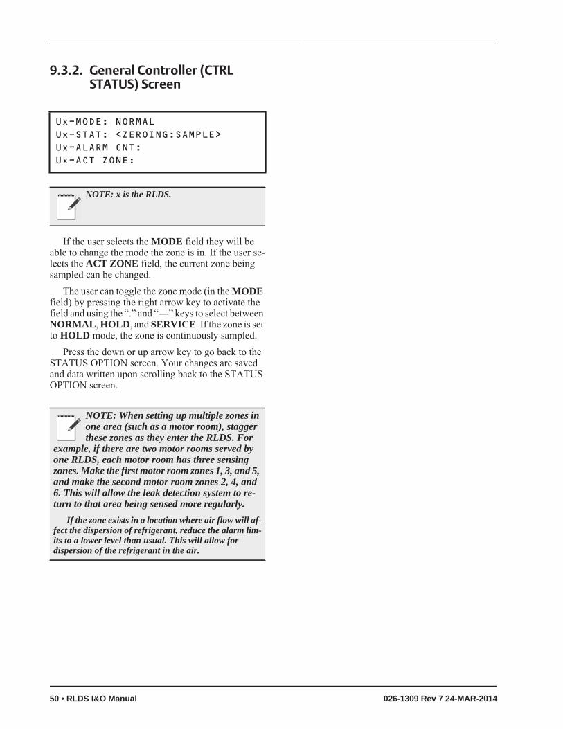
9.3.2. General Controller (CTRL STATUS) Screen
If the user selects the MODE field they will be able to change the mode the zone is in. If the user se-lects the ACT ZONE field, the current zone being sampled can be changed.
The user can toggle the zone mode (in the MODE field) by pressing the right arrow key to activate the field and using the “.” and “—” keys to select between NORMAL, HOLD, and SERVICE. If the zone is set to HOLD mode, the zone is continuously sampled.
Press the down or up arrow key to go back to the STATUS OPTION screen. Your changes are saved and data written upon scrolling back to the STATUS OPTION screen.
Ux-MODE: NORMALUx-STAT: <ZEROING:SAMPLE>Ux-ALARM CNT:Ux-ACT ZONE:
NOTE: x is the RLDS.
NOTE: When setting up multiple zones in one area (such as a motor room), stagger these zones as they enter the RLDS. For
example, if there are two motor rooms served by one RLDS, each motor room has three sensing zones. Make the first motor room zones 1, 3, and 5, and make the second motor room zones 2, 4, and 6. This will allow the leak detection system to re-turn to that area being sensed more regularly.
If the zone exists in a location where air flow will af-fect the dispersion of refrigerant, reduce the alarm lim-its to a lower level than usual. This will allow for dispersion of the refrigerant in the air.
50 • RLDS I&O Manual 026-1309 Rev 7 24-MAR-2014

10 Hand-Held Terminal (HHT) for use with the Gateway and RLDS Controller
The Hand-Held Terminal (HHT) connects directly to the Gateway and is used for the initial setup and to run the system. The HHT allows the user to make set-point and setup adjustments during system start-up, and changes for routine or emergency maintenance. The HHT displays several screens for viewing leak system status, making control set point adjustments, and adjusting at what PPM an alarm should sound. Setpoint changes made through the HHT are trans-ferred to the RLDS controller and overwrite any ex-isting set points.
The HHT shares the communication port with the I/O Net, and while the HHT is plugged in you can get a momentary loss of communication on the I/O Net. This may result in concentrations, showing NONE momentarily.
10.1. HHT Key OperationsThe arrow keys will be used to move between
fields and screens.Special Keys:• F1 - Save current changes and go back to
Screen 1 (Home screen).• F2 - Save current changes and go back to
Screen 3 (SELECT RLDS screen).• CANCEL - Clear an edit field or acknowledge
an alarm on the status screen.• ENTER - Checks if the entry is valid.• Right arrow key - moves to the next editable
field or moves right one character in alpha name fields.
• Left arrow key - moves to the previous edit field or moves left one character in alpha name fields.
• Down arrow key - moves to the next edit field if one is selected or advances to the next screen if no edit field is selected.
• Up arrow key - moves to the previous edit field if one is selected or moves back to the previous screen if no field is selected.
• “.” - Toggle option select fields or scroll alpha characters for names, and acts as a decimal point for floating point numbers.
The period key is the lower-most button on the bottom left of the HHT.
• “—” - Toggle option select fields or scroll alpha characters for names, and acts as a minus sign for numeric entry.
The dash key is the lower-most button on the bot-tom right of the HHT.
NOTE: Editable fields are activated when the right arrow appears next to them.
HHT Key Operations Hand-Held Terminal (HHT) for use with the Gateway and RLDS Controller • 51

11 Main Screens
11.1. Home Screen (F1 Screen)
Press F1 at any point to save changes and display the Home screen:
The HHT is used to display the following on the Home screen:
• RLDS GW-810-3760: Model information• 1.10B04: Version number• FAIL: I/O NET: Displays the operation mode
on the third line of the HHT screen. This indi-cates which type of area controller the RLDS Gateway is attached to. The dip switch 8 is set to ON or OFF. ON = REFLECS, OFF = E2, Einstein. If a fail-ure condition exists with the RLDS Gateway, this line shows one of the following failure messages:
FAIL: I/O NET indicates that no communication with the I/O Net exists, and that communication be-tween the controllers is down.
FAIL: FLASH/CLK indicates the hardware is bad and the Gateway should be replaced.
FAIL: USER CFG indicates that no RLDS units have been found on the network, and have not been configured by the user.
FAIL: RLDS CTRL indicates that one or more RLDS controllers are down.
• PRESS DOWN ARROW indicates what to do next.
11.2. RLDS Enable ScreenThe second screen will show whether a particular
unit is enabled, disabled, or unknown. When the RLDS Gateway first powers up it will show UN-KOWN for all units. It will then start scanning for each unit. If it finds a unit, it marks it as ENABLED.
If an RLDS is not present on the network, the user can mark that RLDS as DISABLED to prevent the Gateway from scanning for that unit. When the unit is disabled, the Gateway stops trying to access the RLDS controller and does not respond to the associa-tion request on the I/O Network.
Press the down arrow to go to the next screen:
11.3. SELECT RLDS Screen (F2 Screen)
Press F2 at any point to save changes and display the SELECT RLDS screen:
The F2 screen allows you to select the desired RLDS. The F2 screen shows the general ONLINE or OFFLINE status for the enabled RLDS controllers. ONLINE means the Gateway is successfully commu-nicating with an enabled RLDS controller. If it is un-known whether an RLDS is present on the network, the screen will display UNKNOWN.
RLDS GW-810-3760 VER: 1.10B04 FAIL: I/O NET (PRESS DOWN ARROW)
NOTE: Pressing the down arrow scrolls you to the next screen.
RLDS LIST:RLDS1: ENABLEDRLDS2: DISABLEDRLDS3: DISABLED
SELECT RLDS: 1 LDS1: ONLINE RLDS2: DISABLED RLDS3: DISABLED
NOTE: SELECT RLDS: 1 defaults to 1.
52 • RLDS I&O Manual 026-1309 Rev 7 24-MAR-2014

Select the desired RLDS by pressing the right ar-row key and selecting the desired RLDS number. Press the down arrow key to prompt you to the Oper-ation Select (OPTION) screen.
The WAITING ON READ FROM RLDS mes-sage displays, and after a short delay prompts you to the Operation Select (OPTION) screen.
11.4. Operation Select (OPTION) Screen
The Operation Select (OPTION) screen enables the user to select the following entry points:
Press the right arrow key to enable you to change the number selection next to OPTION. When a right arrow appears after OPTION, press the number key of the desired screen (1,2, or 3). Press the down arrow key twice to display the selected screen.
• Select 1 to access the RLDS STATUS screenSee Section 11.5., STATUS OPTION Screen.• Select 2 to access the RLDS FAULTS screen
See Section 11.4.2., RLDS FAULTS (SYSTEM FAULTS) screen.
• Select 3 to access the RLDS CONFIG screenSee Section 11.4.3., RLDS Configuration Option
(CONFIG OPTION) Screen
11.4.1. RLDS STATUS (STATUS OPTION) Screen
The STATUS OPTION screen allows you to check individual zones, overall controller status, and diagnostic data. Refer to Section 11.5., STATUS OP-TION Screen to find out more information about ac-cessing these screens.
• ZONE STATUS gives status on individual zones
See Section 11.5.1., Zone Status Screen.• CTRL STATUS is overall controller status
See Section 11.5.2., General Controller (CTRL STATUS) Screen.
• DIAGNOSTICS is diagnostic zone dataSee Section 11.5.3., DIAGNOSTICS Screen 1:
Sensor Data Register.
11.4.2. RLDS FAULTS (SYSTEM FAULTS) screen
From the Operation Select (OPTION) screen, (Section 11.4.) select RLDS FAULTS by pressing the right arrow key, selecting 2, and pressing the down arrow key twice.
The RLDS FAULTS screen will display a list of the system failures associated with the selected RLDS. One failure will be displayed on each line.
The following are failure messages that are used:
CLIPPNG FAULT - A/D out of rangeZERO FAULT - Zero voltage outside factory limitsNO FLOW - No flow on any zonePURGE FLOW - No flow on purgeZONE FLOW - No flow on one or more zonesTRIGGER FAULT - IR Source clock trigger missingCONFIG FAULT - No zones enabled
OPTION: 1 1 = RLDS STATUS 2 = RLDS FAULTS 3 = RLDS CONFIG
NOTE: OPTION: 1 defaults to 1.
STATUS OPTION: 1 = ZONE STATUS 2 = CTRL STATUS 3 = DIAGNOSTICS
NOTE: Once a fault is detected and repaired, the unit will go through an entire cycle and the fault will clear itself and return to normal.
SYSTEM FAULTS
Operation Select (OPTION) Screen Main Screens • 53

LOOP FAULT - Open current loopPRESSURE RANGE - Pressure out of rangeBENCH TEMP - Bench temperature out of rangeBOX TEMP - Box temperature fault
11.4.3. RLDS Configuration Option (CONFIG OPTION) Screen
From the Operation Select (OPTION) screen, (Section 11.4.) select RLDS CONFIG by pressing the right arrow key, selecting 3, and pressing the down arrow key twice. The CONFIG OPTION screen displays and allows the user to configure the selected RLDS:
Press the right arrow key to enable you to change the number selection that appears next to CONFIG OPTION. When a right arrow appears after CON-FIG OPTION, press the number key of the desired screen (1,2, or 3). Press the down arrow key twice to display the selected screen.
• Select 1 to access the General Configuration 1 Screen
See Section 11.4.4., General Configuration 1 Screen.
• Select 2 to access the Time/Date screenSee Section 11.4.8., Time/Date Screen.• Select 3 to access the Calibrate/Refrigerant
screens See Section 11.4.9., Calibrate Gas Screen 1.
11.4.4. General Configuration 1 Screen
From the CONFIG OPTION screen, press the right arrow key and then press the 1 key for RLDS CTRL. Press the down arrow key twice to display the General Configuration 1 (a non-editable) screen:
Press the down arrow key to display the General Configuration 2 screen:
11.4.5. General Configuration 2 Screen
Press the right arrow key to activate the U1 field so you can change the name of the controller. Use the right and left arrow keys to move across the field to select each letter, and remember to use the “.” and “—” keys to toggle letters.
Press the down arrow key to move from the U1 field to the BUZZER field. The default for this field is set to NONE. Use the “.” and “—” keys to scroll through the choices: NONE, ALARM, FAULT, LEAK, SPILL, EVAC, or MN OFF (monitor is of-fline and is no longer monitoring the refrigerant lines).
Press the down arrow key to move from the BUZZER field to the AL ACK field. The default for this field is set to MANUAL, but it is recommended the setting be changed to AUTO so the zone can au-tomatically reset itself after the condition clears.
CONFIG OPTION: 1 1 = RLDS CTRL 2 = TIME/DATE 3 = CALIB GASES
Ux: ENABLED:DISABLEDUx- ZONES: 8 Ux- MODEL: 300Ux- REV : 1.12
NOTE: x is the RLDS currently being ac-cessed.
U1: NAME OF CONTROLLER 1 - BUZZER: NONE1 - AL ACK: MANUAL
NOTE: The “blank” line is used to provide a cursor so the user knows which character they are editing. The “.” and “—” keys are used to scroll an individual character selection or nu-
meric numbers can be entered directly.
54 • RLDS I&O Manual 026-1309 Rev 7 24-MAR-2014
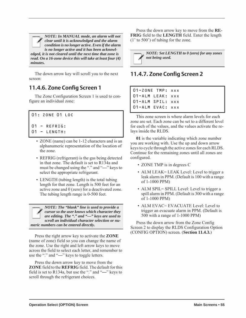
The down arrow key will scroll you to the next screen:
11.4.6. Zone Config Screen 1The Zone Configuration Screen 1 is used to con-
figure an individual zone:
• ZONE (name) can be 1-12 characters and is an alphanumeric representation of the location of the zone.
• REFRIG (refrigerant) is the gas being detected in that zone. The default is set to R134a and must be changed using the “.” and “—” keys to select the appropriate refrigerant.
• LENGTH (tubing length) is the total tubing length for that zone. Length is 500 feet for an active zone and 0 (zero) for a deactivated zone. The tubing length range is 0-500 feet.
Press the right arrow key to activate the ZONE (name of zone) field so you can change the name of the zone. Use the right and left arrow keys to move across the field to select each letter, and remember to use the “.” and “—” keys to toggle letters.
Press the down arrow key to move from the ZONE field to the REFRIG field. The default for this field is set to R134a, but use the “.” and “—” keys to scroll through the refrigerant choices.
Press the down arrow key to move from the RE-FRIG field to the LENGTH field. Enter the length (1’ to 500’) of tubing for the zone.
11.4.7. Zone Config Screen 2
This zone screen is where alarm levels for each zone are set. Each zone can be set to a different level for each of the values, and the values activate the re-lays inside the RLDS.
01 is the variable indicating which zone number you are working with. Use the up and down arrow keys to cycle through the active zones for each RLDS. Continue for the remaining zones until all zones are configured.
• ZONE TMP is in degrees C• ALM LEAK= LEAK Level: Level to trigger a
leak alarm in PPM. (Default is 100 with a range of 1-1000 PPM)
• ALM SPIL= SPILL Level: Level to trigger a spill alarm in PPM. (Default is 300 with a range of 1-1000 PPM)
• ALM EVAC= EVACUATE Level: Level to trigger an evacuate alarm in PPM. (Default is 500 with a range of 1-1000 PPM)
Press the down arrow from the Zone Config Screen 2 to display the RLDS Configuration Option (CONFIG OPTION) screen. (Section 11.4.3.)
NOTE: In MANUAL mode, an alarm will not clear until it is acknowledged and the alarm condition is no longer active. Even if the alarm is no longer active and it has been acknowl-
edged, it is not cleared until the next time that zone is read. On a 16-zone device this will take at least four (4) minutes.
01: ZONE 01 LOC 01 - REFRIG: 01 - LENGTH:
NOTE: The “blank” line is used to provide a cursor so the user knows which character they are editing. The “.” and “—” keys are used to scroll an individual character selection or nu-
meric numbers can be entered directly.
NOTE: Set LENGTH to 0 (zero) for any zones not being used.
01-ZONE TMP: xxx01-ALM LEAK: xxx01-ALM SPIL: xxx01-ALM EVAC: xxx
Operation Select (OPTION) Screen Main Screens • 55

11.4.8. Time/Date ScreenFrom the CONFIG OPTION screen, set the time
and date. Press the right arrow key and select 2. Press the down arrow key twice to open the TIME/DATE screen:
A change in the Time/Date on any one of the RLDS controllers changes ALL of the RLDS control-lers on the network.
Press the right arrow key to edit the fields. The right and down arrow keys scroll downward through the list, while the left or up arrow keys will backspace the arrow so you may go back to change a field.
Press the up arrow key to scroll back up to the CONFIG OPTION screen to calibrate gases. Your changes are saved and the data is written when you scroll back up to the CONFIG OPTION screen.
11.4.9. Calibrate Gas Screen 1
The Calibrate Data message is used to calibrate the gases used. It is read only if the user enters the config-uration screen for HHT screens.
From the CONFIG OPTION screen, press the right arrow key and then press the 3 key for CALIB GASES. Press the down arrow key twice and wait for the WAITING ON READ FROM RLDS message to clear to display the Calibration Gas screens.
Press the down arrow key so the Calibrate Gas Screen 1 will cycle through all gases and view the available gases in the gas library. Press the down ar-row key to cycle Calibrate Gas screens 2 and 3 to complete the calibration process:
11.4.10. Calibrate Gas Screen 2
Use the “.” and “—” keys to scroll through the supported gas/refrigerants.
Press the down arrow key:
11.4.11. Calibrate Gas Screen 3User can select names for each new gas/refriger-
ants by pressing the right arrow key to activate the field and using the “.” and “—” keys to toggle the let-ters.
NOTE: When setting up multiple zones in one area (such as a motor room), stagger these zones as they enter the RLDS. For example, if there are two motor rooms served by one
RLDS, each motor room has three sensing zones. Make the first motor room zones 1, 3, and 5, and make the sec-ond motor room zones 2, 4, and 6. This will allow the leak detection system to return to that area being sensed more regularly.
If the zone exists in a location where air flow will af-fect the dispersion of refrigerant, reduce the alarm lim-its to a lower level than usual. This will allow for dispersion of the refrigerant in the air.
1-DATE: xx-xx-xx1-TIME: xx:xx:xx
NOTE: For TIME, enter military time only.
CAUTION: The Calibrate Gas screens are rarely used. Before modifying values in the Calibration screens, contact your Emerson Re-tail Solutions representative for Correction
Values.
x - R11: xxx.x x - R12: xxx.x x - R22: xxx.x x - R23: xxx.x
NOTE: User enter a floating point number for x.
1 - CURVE 1: xxx1 - CURVE 2: xxx1 - CURVE 3: xxx<blank>
NOTE: User enter a curve number for New Gas Type 1 for x.
56 • RLDS I&O Manual 026-1309 Rev 7 24-MAR-2014

Press the down arrow key:
11.4.11.1. Calibrate Gas Screen 3 Continued
The default gas name is NEW GAS1.
Pressing the down arrow key brings you back to the CONFIG OPTION screen. To move back to the STATUS OPTION screen, first press the up arrow key to go back to the OPTION screen and select 1 for RLDS STATUS. You should now be back at the STATUS OPTION screen.
11.5. STATUS OPTION ScreenFrom the STATUS OPTION screen, you are able
to check zone status (individual zones), ctrl status (overall controller status), and diagnostics (diagnostic zone data).
To display ZONE STATUS: (individual zones), press the right arrow key and press 1. Press the down arrow key twice. The ZONE STATUS screen dis-plays.
11.5.1. Zone Status Screen
The PPM count, alarm status, and alarm acknowl-edge information is displayed for each individual zone.
Press the down arrow key from the Zone Status screen to scroll through the status concentration for each of the zones in use. The PPM concentration will be shown, alarm/failure indication, and if the alarm is acknowledged. If the zone is normal (no alarm detect-ed), the alarm/failure fields and alarm acknowledge field (where LEAK A appears) should be blank.
ACKNOWLEDGING ALARMSIn order to acknowledge an alarm, press the left or
right arrow keys to select the zone and then press the CANCEL key so the A appears next to the alarm. When the A appears, the alarm has been acknowl-edged.
LEAK, SPIL(L), or EVAC(UATE) will display if there is an alarm. If there is a flow problem (failure) for the zone, FLOW displays. A failure cannot be ac-knowledged--only LEAK, SPIL, or EVAC alarms can be acknowledged.
Use the down arrow key to scroll through and view all of the zones.
After you have scrolled through the zones you are back at the STATUS OPTION screen where you can make another selection.
To display CTRL STATUS: (overall controller status), press the right arrow key and press 2. Press the down arrow key twice. The General Controller (CTRL STATUS) screen displays:
11.5.2. General Controller (CTRL STATUS) Screen
1: NEW GAS1 2: NEW GAS2 3: NEW GAS3
3: NEW GAS3
NOTE: The “blank” line is used to provide a cursor so the user knows which character they are editing. The user can use “.” and “—” keys to scroll an individual character selection or
numeric numbers can be entered directly.
STATUS OPTION: 1 = ZONE STATUS 2 = CTRL STATUS 3 = DIAGNOSTICS
01: ZONE 01 LOC1-01: 0 LEAK A 02: ZONE 02 LOC 1-02: A
Ux-MODE: NORMALUx-STAT: <ZEROING:SAMPLE>Ux-ALARM CNT:Ux-ACT ZONE:
STATUS OPTION Screen Main Screens • 57
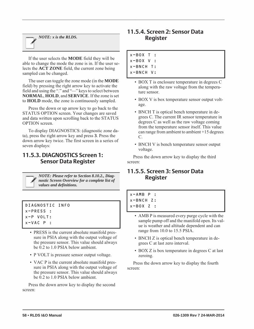
If the user selects the MODE field they will be able to change the mode the zone is in. If the user se-lects the ACT ZONE field, the current zone being sampled can be changed.
The user can toggle the zone mode (in the MODE field) by pressing the right arrow key to activate the field and using the “.” and “—” keys to select between NORMAL, HOLD, and SERVICE. If the zone is set to HOLD mode, the zone is continuously sampled.
Press the down or up arrow key to go back to the STATUS OPTION screen. Your changes are saved and data written upon scrolling back to the STATUS OPTION screen.
To display DIAGNOSTICS: (diagnostic zone da-ta), press the right arrow key and press 3. Press the down arrow key twice. The first screen in a series of seven displays:
11.5.3. DIAGNOSTICS Screen 1: Sensor Data Register
• PRESS is the current absolute manifold pres-sure in PSIA along with the output voltage of the pressure sensor. This value should always be 0.2 to 1.0 PSIA below ambient.
• P VOLT is pressure sensor output voltage.• VAC P is the current absolute manifold pres-
sure in PSIA along with the output voltage of the pressure sensor. This value should always be 0.2 to 1.0 PSIA below ambient.
Press the down arrow key to display the second screen:
11.5.4. Screen 2: Sensor Data Register
• BOX T is enclosure temperature in degrees C along with the raw voltage from the tempera-ture sensor.
• BOX V is box temperature sensor output volt-age.
• BNCH T is optical bench temperature in de-grees C. The current IR sensor temperature in degrees C as well as the raw voltage coming from the temperature sensor itself. This value can range from ambient to ambient +15 degrees C.
• BNCH V is bench temperature sensor output voltage.
Press the down arrow key to display the third screen:
11.5.5. Screen 3: Sensor Data Register
• AMB P is measured every purge cycle with the sample pump off and the manifold open. Its val-ue is weather and altitude dependent and can range from 10.0 to 15.5 PSIA.
• BNCH Z is optical bench temperature in de-grees C at last zero interval.
• BOX Z is box temperature in degrees C at last zeroing.
Press the down arrow key to display the fourth screen:
NOTE: x is the RLDS.
NOTE: Please refer to Section 8.10.2., Diag-nostic Screen Overview for a complete list of values and definitions.
DIAGNOSTIC INFOx-PRESS : x-P VOLT: x-VAC P :
x-BOX T : x-BOX V : x-BNCH T: x-BNCH V:
x-AMB P : x-BNCH Z: x-BOX Z :
58 • RLDS I&O Manual 026-1309 Rev 7 24-MAR-2014

11.5.6. Screen 4: Sensor Data Register
• PEAK C is the current peak to peak A/D counts from detector.
• PEAK V is the current peak to peak voltage from detector.
• AVG V is the running average voltage from de-tector.
• ZERO V is the voltage measured at last zeroing and the IR sensor output that was stored during the last purge cycle.
Press the down arrow key to display the fifth screen:
11.5.7.Screen 5: Sensor Data Register
• NOISE is the largest change in running aver-age: 16-point running average of the noise por-tion of IR bench output. This reading is valuable mainly when refrigerant is NOT pres-ent.
• AU is the current absorbance value.• AVG AU is the running average of absorbance
level (Average Absorbency). In the absence of refrigerant, the absorbency is 0.000AU. When sampling refrigerants, its value varies propor-tionally with the refrigerant concentration.
• BNCH P is PPM in bench, based on zone gas selection (uncorrected).
Press the down arrow key to display the sixth screen:
11.5.8. Screen 6: Sensor Data Register
• STPPPM is PPM corrected to STP (1 atm, 25 deg C).
• BNCH L is micromoles/liter in bench (uncor-rected).
• AMB L is micromoles/liter corrected to ambi-ent pressure.
Press the down arrow key to display the seventh screen:
11.5.9. Screen 7: Communication Statistics
• SENT is total messages sent.• TRY is number of retries needed for a message.• NO is no response after all four tries.• 1: <ct> <ct> <ct> is RLDS 1 count for each sta-
tistic.• 2: <ct> <ct> <ct> is RLDS 2 count for each sta-
tistic.• 3: <ct> <ct> <ct> is RLDS 3 count for each sta-
tistic.Press the down arrow key to go back to the STA-
TUS OPTION screen. Your changes are saved and the data is written. Statistics are cleared on reset.
x-PEAK C: x-PEAK V: x-AVG V: x-ZERO V:
x-NOISE : x-AU : x-AVG AU: x-BNCH P:
x-STPPPM: x-BNCH L: x-AMB L :
SENT TRY NO 1: <ct> <ct> <ct> 2: <ct> <ct> <ct> 3: <ct> <ct> <ct>
STATUS OPTION Screen Main Screens • 59

12 RLDS Setup on REFLECS, E2, and Einstein Controller Interfaces
Dip switch 8 on the Gateway should be set to the OFF position for E2, Einstein and the ON position for REFLECS controllers.
12.1. REFLECS Setup for RLDSSet dip switch 8 to ON and follow the steps for setting
up RLDS units through the REFLECS controller interface:
1. Log on.2. Press 7 for Configuration to reach the CON-
FIGURATION screen.Input Definitions should be set here to show how
the sensor control is linked to the zone. The number of devices and RLDS units are connected to the Gate-way and enabled is the number of address slots the Gateway will use.
3. Press 1 for Input Definitions to reach the IN-PUT DEFINITIONS screen.
4. Pressing the down arrow several times will get you to the input list of SENS01-48. Bd (board) is the address of the Gateway, Pt (point) is the zone and allows you to define where the sensor input comes from.
The board number for the RLDS setup is the ad-dress of the Gateway. If there are three or less RLDS controllers connected to a Gateway, the Gateway ad-dress = the RLDS address. However, if there are more than three RLDS controllers, the second Gateway ad-dress will be the one entered for the board number, but the RLDS controllers are set 1 to 3 on the second Gateway.
5. Press 0 (zero) to go back to the CONFIGURA-TION screen.
6. Press 7 for I/O Brd Setup to reach the I/O BOARD MENU screen.
7. Press 2 to Set Device #’s.The Gateway will react as three 16AI boards. The
number of RLDS controllers plus the real number of 16AIs = the total number of 16AIs to enter in the next step:
8. At the I/O BOARD DEVICE NUMBERS screen, press the down arrow key to reach Number 16AI Boards and enter the number of how many 16AI boards and RLDS controllers there are. Press Enter.
9. Arrow down to the I/O BOARD MENU and press 0 (zero) twice to go back to the MAIN MENU screen.
10.Press 4 for Sensor Control.11.Press 2 for Setup--up to 48 sensor control pro-
grams are allowed. Select one of the 48 units and press Enter to reach the SENSOR SETUP screen.
12.Press the right arrow to move to the Name field to change the name, and press the down or right arrow to move to the (sensor) Type field. Use the “.” and “—” keys to scroll through the op-tions and select IRLDS.
13.Use the arrow keys to move off the active fields and press 0 (zero) twice to go back to the main screen.
12.2. E2 Version 3.01 and below Setup for RLDS (without Gateway)
Set dip switch 8 to OFF and follow the steps for setting up RLDS units through the E2 controller inter-face
1. Log in to the E2 with Level 4 access.
2. Press - Connected I/O Boards
60 • RLDS I&O Manual 026-1309 Rev 7 24-MAR-2014

and Controllers.
3. Under the I/O Network tab, set the number of desired RLDS controllers under IRLDS.
4. Press the key to return to the E2 home screen and save changes.
5. Set the Gateway to 1. Each Gateway can han-dle three RLDS controllers, so if four RLDS controllers are on the network, two Gateways are needed. The first Gateway will be address 1 and the RLDS units are numbered as 1,2,3. The second Gateway will be addressed as 4, but the RLDS is set to 1 because all units on the Gate-way are numbered sequentially 1 to 3. The RLDS controllers are always numbered 1 to 3 when connected to the Gateway.
To see a summary of RLDS controllers on the net-work:
1. Press - Configured Applications.
2. Select 185. for IR Leak Detection.
3. The leak detectors are listed on the status screen. Press the down arrow to highlight a unit and to go the setup screen to enter chan-nel, zone information, and more.
Figure 12-1 - Connected I/O Setup Screen Figure 12-2 - Configured Applications
Figure 12-3 - RLDS Application Setup Screen
E2 Version 3.01 and below Setup for RLDS (without Gateway) RLDS Setup on REFLECS, E2, and Einstein Control-ler Interfaces • 61

12.3. Einstein Setup for RLDS
Set dip switch 8 to OFF and follow the steps for setting up RLDS units through the Einstein controller interface:
1. Log on.2. Press F8 for ACTIONS.3. Press Y for System Setup.4. Press 4 for Network Status/Setup.5. Press 2 for Connected I/O Boards & Control-
lers to open the Network Setup screen.6. Under Boards on I/O Network, set the RLDS
number under IRLDS Controllers.7. Press F9 HOME to go back to the Home
screen.8. Set the Gateway to 1. Each Gateway can han-
dle three RLDS controllers, so if four RLDS controllers are on the network, two Gateways are needed. The first Gateway will be address 1 and the RLDS units are numbered as 1, 2, 3. The second Gateway will be addressed as 4, but the RLDS is set to 1 because all units on the Gateway are numbered sequentially 1 to 3. The RLDS controllers are always numbered 1 to 3 when connected to the Gateway.
To see a summary of RLDS controllers on the net-work:
1. Press F5 for MORE.2. Press L for Leak Detection.3. The leak detectors are listed under See Sum-
mary. Press the down arrow to highlight a unit and press Enter to show the summary of units listed.
The status screen for the selected RLDS controller is shown.
4. F8 for ACTIONS.5. Press B for Setup--you can name the RLDS in
the Name field.6. Press the down arrow to the Num Channels
field to add the number of zones.7. Press F10 to go back and see the current status
of the zones.8. Press F9 HOME to go back to the Home
screen.
62 • RLDS I&O Manual 026-1309 Rev 7 24-MAR-2014

13 RLDS Maintenance
13.1. Warnings and Cautions
13.2. Charcoal FilterThe charcoal filter removes refrigerant gas from
the purge-air stream during the purging process. Re-place the charcoal filter (P/N 275-0275) approximate-ly every six (6) months, when a zero filter fault occurs (fault code <0100>), or after the monitor has been ex-posed to unusually high levels of refrigerant gas, such as after an evacuation alarm.
13.3. Hydrophobic FilterThe hydrophobic filter prevents water from enter-
ing the detector. A zone flow fault will occur (fault code <0800>) if this filter becomes blocked. Replace the hydrophobic filter as required (P/N 572-0980).
13.4. Servicing Air Lines and Replacing Termination Filters
The gas sample line and optional exhaust line should be checked periodically for obvious signs of kinks, damage and contamination. The gas-sample
line and purge-line termination filters prevent dust and dirt from entering the monitor. Both of the filters should be checked periodically.
• A zone flow fault will occur (fault code <0800>) if the gas-sample line filter becomes blocked.
• A purge flow auto will occur (fault code <1000>) if the purge-line filter becomes blocked.
Remove the filter from the line and replace it with a new one (P/N 275-0300).
13.5. Annual MaintenanceTo assure peak performance and accuracy of the
RLDS, it is recommended that maintenance be per-formed on an annual basis. This maintenance routine involves replacing all end-of-line filters, charcoal fil-ter, and internal dust filter/water stop. These filters prevent dust and dirt from damaging components of the RLDS such as the solenoid manifolds, infrared sensor, and sample pump. If the RLDS is installed in areas where dust and particulate levels are high, it is recommended that the filters be changed approxi-mately every after three to six months to prevent sys-tem faults caused by purge or zone restrictions.
13.5.1. Checking Pump and Bench Diagnostics
During maintenance is a good time to check the di-agnostic screen (“DIAG”) to verify that the detector voltage and pump pressures are within optimum pa-rameters. If they are not, a voltage adjustment or scheduled pump replacement could head off a system fault.
To check the pump and detector diagnostics, enter the diagnostic screen by using the front panel keypad and pressing the arrow key to highlight DIAG.
WARNING: Shock hazard! Always disconnect the power supply before opening the enclosure of the monitor.
CAUTION: When working inside the instru-ment be very careful not to dislodge any electri-cal wiring or pneumatic tubing. The RLDS contains sensitive electronic components that
can be easily damaged. Be careful not to touch or dis-turb any of these components.
Warnings and Cautions RLDS Maintenance • 63

For information about the Diagnostic Screen, refer to Section 8.10., The Diagnostic Screen.
13.5.2. Gas TestingTo verify monitor operation, gas testing is recom-
mended. This ensures the integrity of the sample tub-ing is still intact and the sensor is responding to gas. Gas testing can be done either by “bump testing” or by performing a gas verification test.
A bump test is done by exposing each zone to ei-ther a liquid or gaseous refrigerant. The test verifies the sample path and checks that the sensor is respond-ing to gas. The refrigerant concentration is not deter-mined.
A gas verification test is done by exposing each zone to a known concentration of gas and verifying that the display readings are within 10% of the applied gas. Gas verification kits for a variety of refrigerant types are available which contain certified PPM lev-els of test gas. For more information about gas verifi-cation test, refer to Section 14.1.1., Testing with Gas Verification Kit.
Figure 13-1 - Navigating to the Diagnostic Screen
64 • RLDS I&O Manual 026-1309 Rev 7 24-MAR-2014
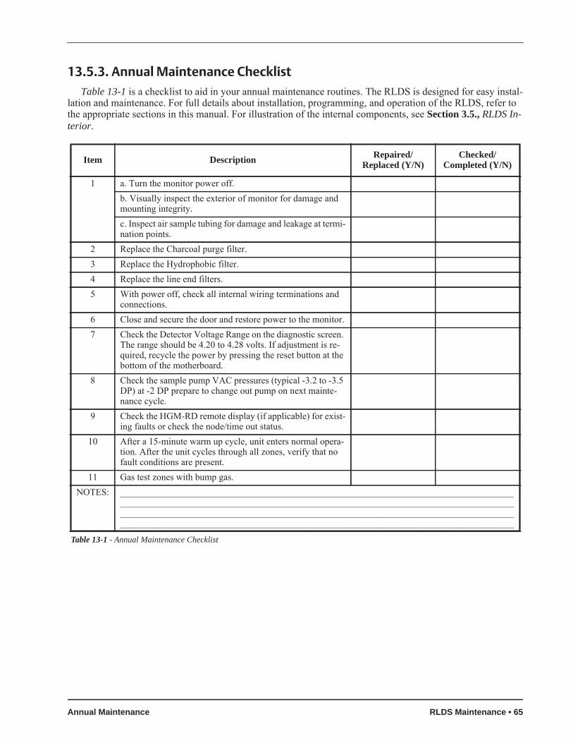
13.5.3. Annual Maintenance ChecklistTable 13-1 is a checklist to aid in your annual maintenance routines. The RLDS is designed for easy instal-
lation and maintenance. For full details about installation, programming, and operation of the RLDS, refer to the appropriate sections in this manual. For illustration of the internal components, see Section 3.5., RLDS In-terior.
Item Description Repaired/Replaced (Y/N)
Checked/Completed (Y/N)
1 a. Turn the monitor power off.b. Visually inspect the exterior of monitor for damage and mounting integrity.c. Inspect air sample tubing for damage and leakage at termi-nation points.
2 Replace the Charcoal purge filter.3 Replace the Hydrophobic filter.4 Replace the line end filters.5 With power off, check all internal wiring terminations and
connections.6 Close and secure the door and restore power to the monitor.7 Check the Detector Voltage Range on the diagnostic screen.
The range should be 4.20 to 4.28 volts. If adjustment is re-quired, recycle the power by pressing the reset button at the bottom of the motherboard.
8 Check the sample pump VAC pressures (typical -3.2 to -3.5 DP) at -2 DP prepare to change out pump on next mainte-nance cycle.
9 Check the HGM-RD remote display (if applicable) for exist-ing faults or check the node/time out status.
10 After a 15-minute warm up cycle, unit enters normal opera-tion. After the unit cycles through all zones, verify that no fault conditions are present.
11 Gas test zones with bump gas.NOTES: ____________________________________________________________________________________
____________________________________________________________________________________________________________________________________________________________________________________________________________________________________________________________
Table 13-1 - Annual Maintenance Checklist
Annual Maintenance RLDS Maintenance • 65

13.6. Replacement Parts and Part Descriptions
Part Number Item DescriptionStandard Accessories and Replacement Parts
808-2004 RLDS 4 Zone, 5 line-end filters, charcoal filter, t-bolt bracket, 120/240 VAC 50/60 Hz808-2005 RLDS 4 Zone, 5 line-end filters, charcoal filter, t-bolt bracket, 120/240 VAC 50/60 Hz, with
HHT and Gateway808-2008 RLDS 8 Zone, 9 line-end filters, charcoal filter, t-bolt bracket, 120/240 VAC 50/60 Hz808-2009 RLDS 8 Zone, 9 line-end filters, charcoal filter, t-bolt bracket, 120/240 VAC 50/60 Hz, with
HHT and Gateway808-2012 RLDS 12 Zone, 13 line-end filters, charcoal filter, t-bolt bracket, 120/240 VAC 50/60 Hz808-2013 RLDS 12 Zone, 13 line-end filters, charcoal filter, t-bolt bracket, 120/240 VAC 50/60 Hz,
with HHT and Gateway808-2016 RLDS 16 Zone, 17 line-end filters, charcoal filter, t-bolt bracket, 120/240 VAC 50/60 Hz808-2017 RLDS 16 Zone, 17 line-end filters, charcoal filter, t-bolt bracket, 120/240 VAC 50/60 Hz,
with HHT and Gateway808-2018 RLDS 16 Zone, 17 line-end filters, charcoal filter, t-bolt bracket, 120/240 VAC 50/60 Hz810-3760 RLDS Gateway573-0000 RLDS 4 Zone Expansion Kit275-0275 Charcoal Filter572-0980 Hydrophobic Air Filter275-0315 Line-end Filter Only275-0300 Line-end Filter Assembly275-0304 Two-way Splitter Kit, contains 1 two-way push-fit splitter, 2 line-end filters (sample tubing
not included)275-0305 Three-way Splitter Kit, contains 1 three-way push-fit splitter, 3 line-end filters (sample tub-
ing not included)270-0810 ¼” Sample Tubing (100 ft.)275-0280 R-22 Gas Verification Kit275-0281 R-134a Gas Verification Kit275-0282 R-123 Gas Verification Kit275-0283 Variable Flow Regulator275-0284 1031 Cylinder, 100 PPM R-22275-0285 1031 Cylinder, 100 PPM R-134a275-0286 1031 Cylinder, 100 PPM R-123
CO2-RLDS Units
808-2104 RLDS-Co2 4 Zone
808-2105 RLDS-Co2 4 Zone, w/HHT & Gateway
808-2108 RLDS-Co2 8 Zone
808-2109 RLDS-Co2 8 Zone, w/HHT & Gateway
Table 13-2 - RLDS Part Numbers and Descriptions
66 • RLDS I&O Manual 026-1309 Rev 7 24-MAR-2014
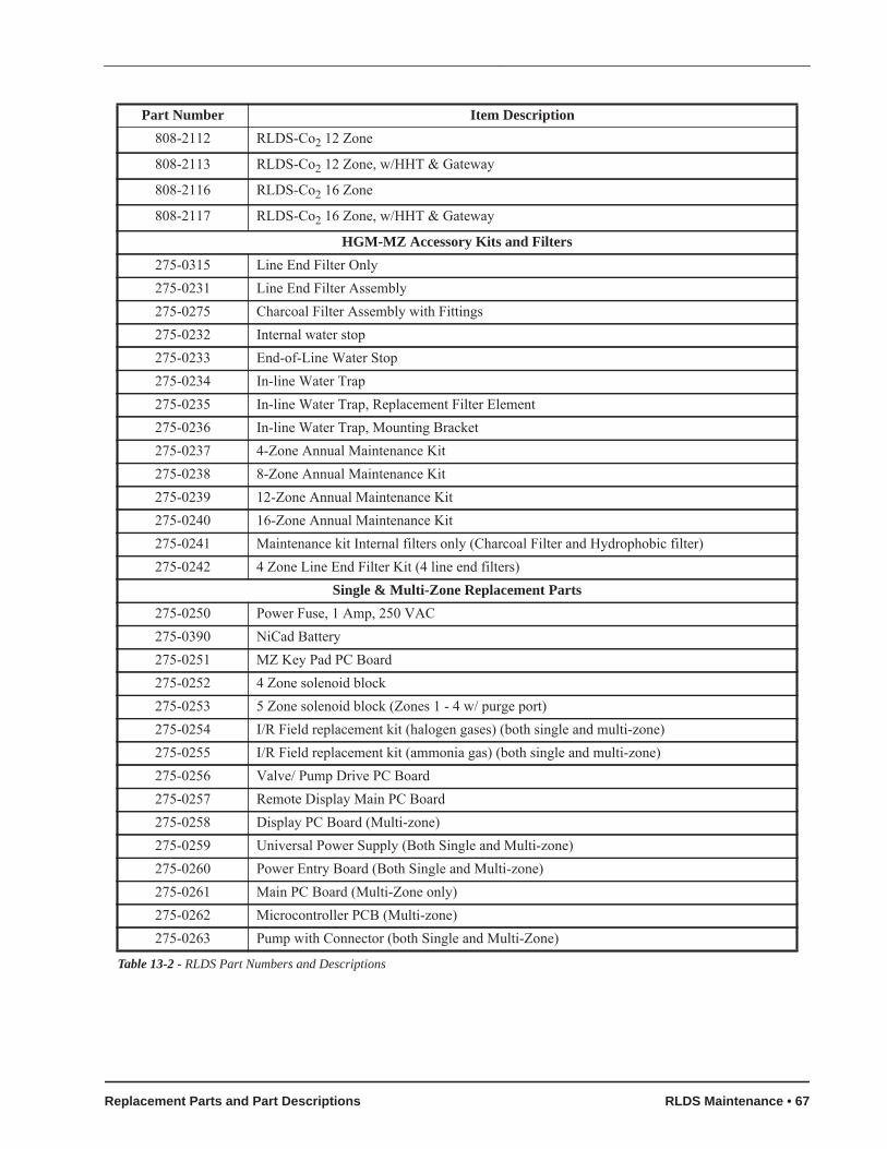
808-2112 RLDS-Co2 12 Zone
808-2113 RLDS-Co2 12 Zone, w/HHT & Gateway
808-2116 RLDS-Co2 16 Zone
808-2117 RLDS-Co2 16 Zone, w/HHT & Gateway
HGM-MZ Accessory Kits and Filters275-0315 Line End Filter Only275-0231 Line End Filter Assembly275-0275 Charcoal Filter Assembly with Fittings275-0232 Internal water stop275-0233 End-of-Line Water Stop275-0234 In-line Water Trap275-0235 In-line Water Trap, Replacement Filter Element275-0236 In-line Water Trap, Mounting Bracket275-0237 4-Zone Annual Maintenance Kit275-0238 8-Zone Annual Maintenance Kit275-0239 12-Zone Annual Maintenance Kit275-0240 16-Zone Annual Maintenance Kit275-0241 Maintenance kit Internal filters only (Charcoal Filter and Hydrophobic filter)275-0242 4 Zone Line End Filter Kit (4 line end filters)
Single & Multi-Zone Replacement Parts275-0250 Power Fuse, 1 Amp, 250 VAC275-0390 NiCad Battery275-0251 MZ Key Pad PC Board275-0252 4 Zone solenoid block275-0253 5 Zone solenoid block (Zones 1 - 4 w/ purge port) 275-0254 I/R Field replacement kit (halogen gases) (both single and multi-zone)275-0255 I/R Field replacement kit (ammonia gas) (both single and multi-zone)275-0256 Valve/ Pump Drive PC Board275-0257 Remote Display Main PC Board275-0258 Display PC Board (Multi-zone)275-0259 Universal Power Supply (Both Single and Multi-zone)275-0260 Power Entry Board (Both Single and Multi-zone)275-0261 Main PC Board (Multi-Zone only)275-0262 Microcontroller PCB (Multi-zone)275-0263 Pump with Connector (both Single and Multi-Zone)
Part Number Item Description
Table 13-2 - RLDS Part Numbers and Descriptions
Replacement Parts and Part Descriptions RLDS Maintenance • 67


14 Appendix: RLDS Calibration
14.1. Calibration CheckThe RLDS provides for the continuous monitoring
of refrigerant gas levels in up to 16 separate test zones or channels. The instrument can be programmed to monitor a variety of refrigerants and independent leak (small), spill (medium), and evacuation (large) levels may be designated for each zone. Below are the steps for testing the calibration or gas verification of the RLDS unit using a gas verification kit and reference gas cylinder to measure the calibration of the unit.
14.1.1. Testing with Gas Verification Kit
Materials Required• Reference gas cylinder• Variable flow regulator• RLDS unit
Steps1. Go to Step 3 if the RLDS is powered up and
communicating.
Verify that the RLDS is communicating on power up: In the upper left corner of the RLDS screen, the message CHECK NODE will dis-play first. When the unit is communicating properly, CHECK NODE will be replaced by the name programmed into the unit.
2. When the unit is communicating normally, it will be in warm-up mode. Allow the warm up cycle to complete before proceeding to the next step (approximately 15 minutes.).
3. Connect:• The variable regulator (P/N 275-0283) to
the reference gas cylinder.• The 3/16” tubing to the output of the regu-
lator.4. Disconnect the existing tubing from Zone 1 on
the RLDS.
5. From the RLDS Main menu, press the Enter button and select System Setup.
1. From the SETUP menu, select SYSTEM.
2. Navigate to Zone Hold and set to 15 minutes.
3. Select ReZero Mode and change to Auto.
4. Return to the Main Setup by pressing the ESC button.
6. Enter the Zones menu from the Main Menu. In Zone 1:
1. Select Refrigerant and change the selection to match the type of refrigerant located on the reference cylinder.
2. Select Distance and change to 5 ft.
3. Return to the System Menu by pressing the ESC button twice.
7. From the RLDS System Menu, press the button that corresponds to Zones on the menu to go into the Zone View Menu.
1. Select the zone at the top level screen.
2. Press and hold down the ENTER key until the unit beeps. The word HOLDING will blink in the status box.
3. While in the hold mode, further investigation of the zone's status can be made by navigat-ing to that zone’s Setup Screen 1.
4. To release the zone from the Hold Mode, press and hold down the ENTER key until the unit beeps and the screen display returns to normal.
8. Arrow over to System Setup.
Enter the Diagnostic screen by pressing DIAG.9. Verify that the unit is not in a purge cycle. This
can be done by verifying the airflow in Zone 1. Review and record the pressure (PRES) read-ing in the diagnostic screen. If the unit is in a purge cycle, wait until PURGING stops flash-ing and then review and record the PRES read-ing in on the diagnostic screen.
10.Connect the tubing from the reference flow regulator to Zone 1 on the manifold of the RLDS.
NOTES:• The RLDS Fault LED may illuminate until
gas starts to flow from the reference cylinder to the RLDS. The pressure should be below the
Calibration Check Appendix: RLDS Calibration • 69

original reading. If the reading does not drop, the unit may be in the purge cycle. If so, wait until the purge cycle ends before continuing. Slowly adjust the variable flow regulator in a clockwise direction until the pressure is the same as the original reading.
• You may have to block or partially block the relief valve on the variable pressure regula-tor in order to achieve the appropriate pres-sure. Allow about 1 minute to stabilize, and then read the first ppm value in the diagnostics screen. The reading should be within +10% of the actual concentration listed on the cylinder.
• The unit may go into a purge cycle during the test process. If this happens, the ppm read-ing will drop to approximately 0. This does not affect the verification results. However, in or-der to obtain a valid ppm reading, the unit must be drawing from Zone 1.
11.Close the reference gas cylinder by adjusting the variable flow regulator in a counterclock-wise direction until it is fully closed. Reset Zone 1 information (distance, refrigerant, zone hold time) as desired for normal operation.
12.If the reading in Step 10 is not within +10% of the actual concentration listed on the cylinder, verify:
• The pressure reading from Step 9.• The tubing is securely connected to the cyl-
inder and Zone 1 input port.• The proper refrigerant is selected (Step 6).• The unit is in hold for Zone 1.• That there is proper pressure from variable
flow regulator (Step 10).• That enough time was given for readings to
stabilize and the reading was not taken dur-ing a purge cycle (Steps 9 and 10).
If the unit still does not measure within +10% of the concentration listed on the cylinder, please contact Emerson Retail Solutions at 770-425-2724.
70 • RLDS I&O Manual 026-1309 Rev 7 24-MAR-2014
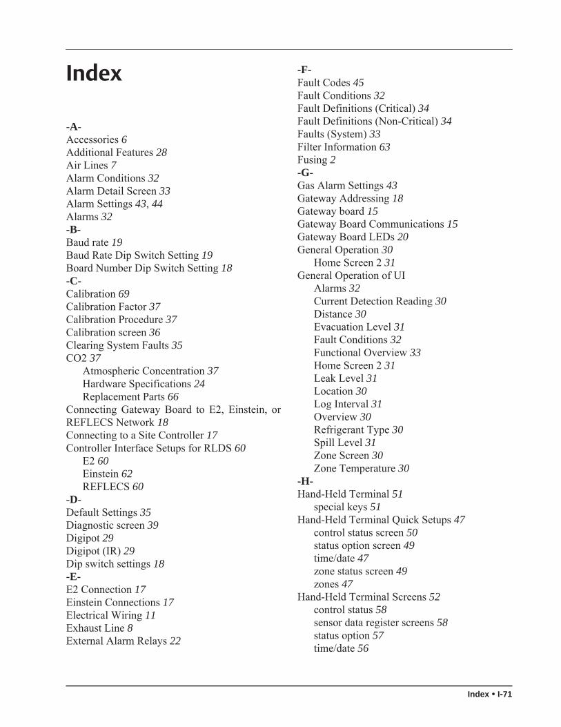
Index
-A-Accessories 6Additional Features 28Air Lines 7Alarm Conditions 32Alarm Detail Screen 33Alarm Settings 43, 44Alarms 32-B-Baud rate 19Baud Rate Dip Switch Setting 19Board Number Dip Switch Setting 18-C-Calibration 69Calibration Factor 37Calibration Procedure 37Calibration screen 36Clearing System Faults 35CO2 37
Atmospheric Concentration 37Hardware Specifications 24Replacement Parts 66
Connecting Gateway Board to E2, Einstein, orREFLECS Network 18Connecting to a Site Controller 17Controller Interface Setups for RLDS 60
E2 60Einstein 62REFLECS 60
-D-Default Settings 35Diagnostic screen 39Digipot 29Digipot (IR) 29Dip switch settings 18-E-E2 Connection 17Einstein Connections 17Electrical Wiring 11Exhaust Line 8External Alarm Relays 22
-F-Fault Codes 45Fault Conditions 32Fault Definitions (Critical) 34Fault Definitions (Non-Critical) 34Faults (System) 33Filter Information 63Fusing 2-G-Gas Alarm Settings 43Gateway Addressing 18Gateway board 15Gateway Board Communications 15Gateway Board LEDs 20General Operation 30
Home Screen 2 31General Operation of UI
Alarms 32Current Detection Reading 30Distance 30Evacuation Level 31Fault Conditions 32Functional Overview 33Home Screen 2 31Leak Level 31Location 30Log Interval 31Overview 30Refrigerant Type 30Spill Level 31Zone Screen 30Zone Temperature 30
-H-Hand-Held Terminal 51
special keys 51Hand-Held Terminal Quick Setups 47
control status screen 50status option screen 49time/date 47zone status screen 49zones 47
Hand-Held Terminal Screens 52control status 58sensor data register screens 58status option 57time/date 56
Index • I-71

zone status 57Home Screen 2 31-IInstallation 6Installation Considerations
inspection 6Interior diagrams 10-L-Location of Monitor 6Logic Diagram 41-M-Maintenance 63
Annual maintenance 63Charcoal filter 63Checklist 65Gas testing 64Hydrophobic filter 63Pump and Bench Diagnostics 63
Monitoring Levels 3Mounting 6Multiple Refrigerants 4-N-Node Address Setting, see Node Address 17-O-Overview 3-P-Part Numbers 66Password 28Placement in Mechanical Room 5Programming the RLDS 25
Additional Features 28Alarm Acknowledge (ACK) Mode 26Audible Alarm 26DET Digipot 29Detection Limit 27IR Digipot 29Location 26Loop2 Factor 27Navigation 25Node Address 28Number of Zones 26Password 28Power-up 25Re-Zero Mode 27Sensor Temp Coefficient 29Service Timeout 28
Setup Screen 1 25Setup Screen 2 26Setup Screen 3 28Zone Hold Mode 27Zone Hold Time 27
Purge Line 7-R-REFLECS Connection 17Refrigerants 43Replacement Parts 66RS485 I/O Termination Jumpers 20-S-Safety Precautions 1Sample Intake Lines 8Sampling Points 4Screw Locations 6Service Mode 40Setup Screen 1 25Setup Screen 2 26Setup Screen 3 28Setup Screen Map 41Specifications 23Splitter Kits 9-T-Termination switch settings 17Terminator Settings 17Troubleshooting
Fault Codes 45Tubing Considerations 7-W-Warning and Caution Statements 2Warnings and Cautions 6, 11Wire Connection 18-Z-Zone Hold Mode 27Zone Hold Time 27Zone Screen 30
I-72 • RLDS I&O Manual 026-1309 Rev 7 24-MAR-2014


The contents of this publication are presented for informational purposes only and they are not to be construed as warranties or guarantees, express or implied, regarding the products or services describedherein or their use or applicability. Emerson Climate Technologies Retail Solutions, Inc. and/or its affiliates (collectively “Emerson”), reserves the right to modify the designs or specifications of suchproducts at any time without notice. Emerson does not assume responsibility for the selection, use or maintenance of any product. Responsibility for proper selection, use and maintenance of any productremains solely with the purchaser and end-user.
026-1309 24-MAR-2014 Emerson is a trademark of Emerson Electric Co. ©2014 Emerson Climate Technologies Retail Solutions, Inc. All rights reserved.