Leak Detection and Location Technology … Detection and Location Technology ... Leak Detection and...
27
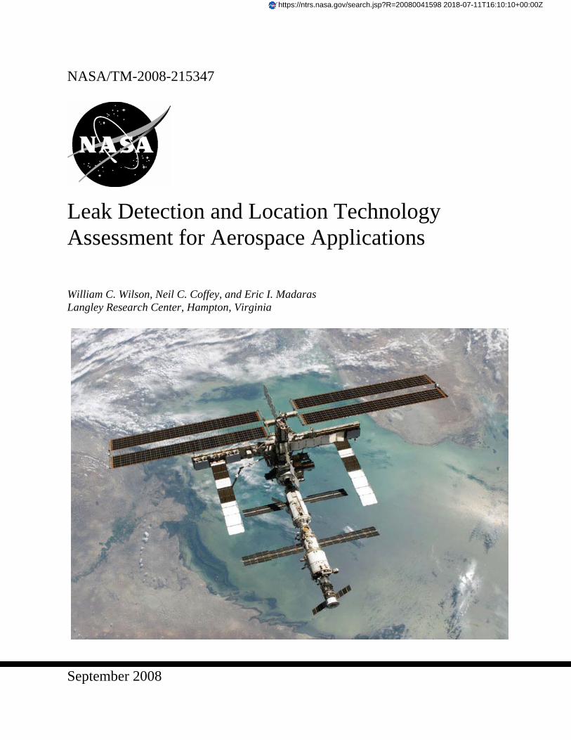
September 2008 NASA/TM-2008-215347 Leak Detection and Location Technology Assessment for Aerospace Applications William C. Wilson, Neil C. Coffey, and Eric I. Madaras Langley Research Center, Hampton, Virginia https://ntrs.nasa.gov/search.jsp?R=20080041598 2018-07-11T16:10:10+00:00Z
Transcript of Leak Detection and Location Technology … Detection and Location Technology ... Leak Detection and...
September 2008
NASA/TM-2008-215347
Leak Detection and Location Technology Assessment for Aerospace Applications William C. Wilson, Neil C. Coffey, and Eric I. Madaras Langley Research Center, Hampton, Virginia
https://ntrs.nasa.gov/search.jsp?R=20080041598 2018-07-11T16:10:10+00:00Z
The NASA STI Program Office . . . in Profile
Since its founding, NASA has been dedicated to the advancement of aeronautics and space science. The NASA Scientific and Technical Information (STI) Program Office plays a key part in helping NASA maintain this important role.
The NASA STI Program Office is operated by Langley Research Center, the lead center for NASA’s scientific and technical information. The NASA STI Program Office provides access to the NASA STI Database, the largest collection of aeronautical and space science STI in the world. The Program Office is also NASA’s institutional mechanism for disseminating the results of its research and development activities. These results are published by NASA in the NASA STI Report Series, which includes the following report types:
• TECHNICAL PUBLICATION. Reports of
completed research or a major significant phase of research that present the results of NASA programs and include extensive data or theoretical analysis. Includes compilations of significant scientific and technical data and information deemed to be of continuing reference value. NASA counterpart of peer-reviewed formal professional papers, but having less stringent limitations on manuscript length and extent of graphic presentations.
• TECHNICAL MEMORANDUM. Scientific
and technical findings that are preliminary or of specialized interest, e.g., quick release reports, working papers, and bibliographies that contain minimal annotation. Does not contain extensive analysis.
• CONTRACTOR REPORT. Scientific and
technical findings by NASA-sponsored contractors and grantees.
• CONFERENCE PUBLICATION. Collected
papers from scientific and technical conferences, symposia, seminars, or other meetings sponsored or co-sponsored by NASA.
• SPECIAL PUBLICATION. Scientific,
technical, or historical information from NASA programs, projects, and missions, often concerned with subjects having substantial public interest.
• TECHNICAL TRANSLATION. English-
language translations of foreign scientific and technical material pertinent to NASA’s mission.
Specialized services that complement the STI Program Office’s diverse offerings include creating custom thesauri, building customized databases, organizing and publishing research results ... even providing videos. For more information about the NASA STI Program Office, see the following: • Access the NASA STI Program Home Page at
http://www.sti.nasa.gov • E-mail your question via the Internet to
[email protected] • Fax your question to the NASA STI Help Desk
at (301) 621-0134 • Phone the NASA STI Help Desk at
(301) 621-0390 • Write to:
NASA STI Help Desk NASA Center for AeroSpace Information 7115 Standard Drive Hanover, MD 21076-1320
National Aeronautics and Space Administration Langley Research Center Hampton, Virginia 23681-2199
September 2008
NASA/TM-2008-215347
Leak Detection and Location Technology Assessment for Aerospace Applications William C. Wilson, Neil C. Coffey, and Eric I. Madaras Langley Research Center, Hampton, Virginia
Available from: NASA Center for AeroSpace Information (CASI) National Technical Information Service (NTIS) 7115 Standard Drive 5285 Port Royal Road Hanover, MD 21076-1320 Springfield, VA 22161-2171 (301) 621-0390 (703) 605-6000
The use of trademarks or names of manufacturers in this report is for accurate reporting and does not constitute an official endorsement, either expressed or implied, of such products or manufacturers by the National Aeronautics and Space Administration.
Acronym List
AE Acoustic Emission COTS Commercial Off-The-Shelf CSIRO Commonwealth Scientific and Industrial Research Organisation DIDS Distributed Impact Detection System DSP Digital Signal Processing ESA European Space Agency EVA Extra Vehicular Activity FPGA Field Programmable Gate Array IR Infrared Radiation ISS International Space Station IVHM Integrated Vehicle Health Management MAC Medium Access Control MEMS MicroElectroMechanical Systems MMOD MicroMeteoroid and Orbital Debris RF Radio Frequency RFID Radio Frequency Identification RMS Root Mean Squared SAW Surface Acoustic Wave SBIR Small Business Innovation Research SHM Structural Health Monitoring SoC System on a Chip sps samples per second TRL Technology Readiness Level TSMP Time Synchronized Mesh Protocol ULD Ultrasonic Leak Detection
1
Table of Contents
1. INTRODUCTION ...........................................................................................................................................2 1.1. BACKGROUND ............................................................................................................................................2 1.2. PURPOSE AND SCOPE OF THIS STUDY .........................................................................................................3
2. LEAK DETECTION METHODS..................................................................................................................3 2.1. CONTACT....................................................................................................................................................3
2.1.1. Ultrasonic Methods............................................................................................................................3 2.1.2. Other Contact Methods......................................................................................................................4
2.2. NONCONTACT ............................................................................................................................................5 2.2.1. Optical Methods.................................................................................................................................5 2.2.2. Chemical Detection............................................................................................................................6 2.2.3. Gas Venting and Attitude Reaction....................................................................................................6 2.2.4. Ultrasonic Methods............................................................................................................................6
3. WIRELESS SENSOR NODES.......................................................................................................................8 3.1. MICROCONTROLLER BASED MOTES ...........................................................................................................8 3.2. MICROPROCESSOR BASED MOTES..............................................................................................................9 3.3. SYSTEM-ON-A-CHIP (SOC) BASED MOTES .................................................................................................9
4. ISS APPLICATION ......................................................................................................................................10 4.1. SCORING SYSTEM .....................................................................................................................................10
4.1.1. Evaluation Categories (Requirements)............................................................................................10 4.1.2. Detect Leak and Provide its Location..............................................................................................10 4.1.3. Complete System Available & Operational .....................................................................................10 4.1.4. Autonomous Operation ....................................................................................................................10 4.1.5. Wireless Communications (Where applicable)................................................................................10 4.1.6. Low Power Operation......................................................................................................................11 4.1.7. Low Impact Integration ...................................................................................................................12 4.1.8. Installation, Operation & Maintenance Procedures for Astronauts................................................12 4.1.9. Flight Qualification for ISS Installation ..........................................................................................12 4.1.10. Miniature Size..................................................................................................................................12
4.2. RESULTS...................................................................................................................................................12 4.2.1. Handheld Units ................................................................................................................................14 4.2.2. Desktop and Rack-mount Units .......................................................................................................14 4.2.3. Industrial Monitoring Systems.........................................................................................................14 4.2.4. Other Platforms & Prototypes .........................................................................................................14 4.2.5. Leading Candidate System...............................................................................................................14
5. FUTURE DIRECTIONS...............................................................................................................................15
CONCLUSIONS ....................................................................................................................................................16
REFERENCES.......................................................................................................................................................16
APPENDIX A.........................................................................................................................................................20
2
Abstract
Micro Meteoroid and Orbital Debris (MMOD) and other impacts can cause leaks in the International Space Station and other aerospace vehicles. The early detection and location of leaks is paramount to astronaut safety. Therefore this document surveys the state of the art in leak detection and location technology for aerospace vehicles.
1. Introduction
In “NASA’s Implementation Plan for International Space Station Continuing Flight,” Micrometeoroid and Orbital Debris (MMOD) are “recognized as a continuing concern for the ISS, the Shuttle, and other spacecraft [1].” The location of small leaks is difficult due to reflections from surrounding structures, audible noise from equipment, and normal atmospheric flows. For these reasons, the report identifies NASA’s ongoing research into improved leak detection.
On June 25, 1997, a cargo ship collided with the Mir space station, causing damage to the solar panels and
creating a leak in the Spektr module [2]. The Mir began leaking again in November of 1997, due to a hatch malfunction on the Kvant-2 module [3]. In October of 1999, another leak occurred, in a hatch between the Spektr module and the Mir core [4]. The leak was not repaired until April of 2000 [5]. During the search for the leak and its repair, air continued to escape.
International Space Station (ISS) detected its first leak during initial assembly of an air lock, which began
leaking shortly after its installation in July of 2001 [6]. The small leak did not cause concern. The leak was later traced to a faulty valve in an air circulation duct between the air lock and the rest of the station [7]. The valve was capped in order to prevent further leakage.
In 2004, a braided flex hose, which was part of the window in the U.S. Destiny module of the ISS, began to leak
[8]. The probable cause for the leak was fatigue damage (from astronauts using the hose as a handhold while viewing out the window). The first attempt at finding the leak, by using a handheld ultrasonic leak detector, was unsuccessful due to the surrounding noise emanating from payload racks. The leak was found on the second attempt, when nearby instrumentation and payload racks were turned off.
Both Mir and ISS space stations have experienced problems with leaks. Any long duration space vehicle may
face similar problems, as well. Currently, leak detection (not location) is being performed by monitoring the air pressure and setting off alarms when the pressure drops. After detection of a leak, leak location is performed using a variety of methods (listening for hissing, closing hatches, using handheld ultrasonic detectors, etc.). These methods are not 100% reliable. Also, significant time is needed to locate leaks, during which valuable resources are lost.
1.1. Background
Research work done in 1990 examined leaks from seals, leaks from impacts and cracks, and thermal techniques
for leak detection [9]. The resulting report selected pressure measurements as the best way to detect leaks across seals, and acoustic emission as the best way to detect leaks from impacts, cracks and holes in the external shell. The thermal imaging techniques were determined to be technically feasible, but were removed from consideration because of programmatic constraints.
Another report from 2000 explored remote sensing technology for detection of H2 and He leaks in air. The
report assessed each technique for suitability (whether it could detect leaks), sensitivity, and NASA Technology Readiness Level (TRL) [10]. The report addressed technologies that are not present in this document. These technologies are not included here because they are primarily for detection of H2 and He leaks in air, and are not suitable for detection of atmospheric leaks to the vacuum of space.
3
This document extends the previous work and attempts to catalog the current state of the art in leak detection methods for aerospace vehicles.
1.2. Purpose and Scope of this Study
Since leaks on the ISS are a high priority, this document will focus on technology that is suitable for retrofitting
onto the space station. This focus is narrow; however, the proposed solution should be directly applicable to other space habitats and vehicles. Because mass, volume, power and costs are always a concern when developing space hardware, any solution must minimize these parameters to be successful. Adding wiring to existing space systems is extremely expensive; the use of wireless networks would avoid costly redesign to route network cables and the costs of performing safety recertification [11]. This will constrain the trade space to wireless solutions for communications, as well as the use of batteries or energy harvesting for power.
Although detection of leaks is paramount, current pressure gauges on the space station are sufficient for the
detection of leaks. The use of pressure gauges is, however, not sufficient for discovering the location of leaks any more precisely than identifying the module that is leaking. Therefore, anything that can find leaks quickly, as well as detect leaks, is considered a better system than one that can only detect leaks. Although many different technologies will be presented for leak detection and location in this document, the scope of technologies considered for advocacy will be limited to those that can be retrofitted onto the space station.
Current leak detection/location methods can be divided into two broad categories: contact and noncontact
methods (both of which are presented in Section 2). Section 3 will present the current processing and wireless node technology that is available for use in leak detection. Section 4 presents a survey of the currently available Commercial Off-The-Shelf (COTS) leak detection products applicable to ISS, and Section 5 presents recommendations for future development.
2. Leak Detection Methods
2.1. Contact 2.1.1. Ultrasonic Methods
Ultrasonic clamp-on flow meters, that use mass or volume balance techniques, can be attached to pipelines to detect small leaks. These devices use sonic profiles and accurate flow rate tracking to detect leaks. They are, however, not applicable to aerospace vehicles because they are slow. Furthermore, they do not identify the location of the small leaks [12].
Acoustic emission is capable of detecting ice and foam impacts on the leading edge of the space shuttle wing.
Although an initial impact detector has been developed and flown on the space shuttle, there remains a need to improve bandwidth, communication reliability, radiation tolerance, and battery life [13]. Impact hammer tests provided acoustic emission data on the Shuttle Endeavour’s wing leading edge and wing spar in the range of 10 to 150 KHz. The tests highlighted future upgrades to the existing wireless impact monitoring systems [14].
Acoustic emission was also explored as a method for detecting and locating atmospheric leaks onboard the ISS.
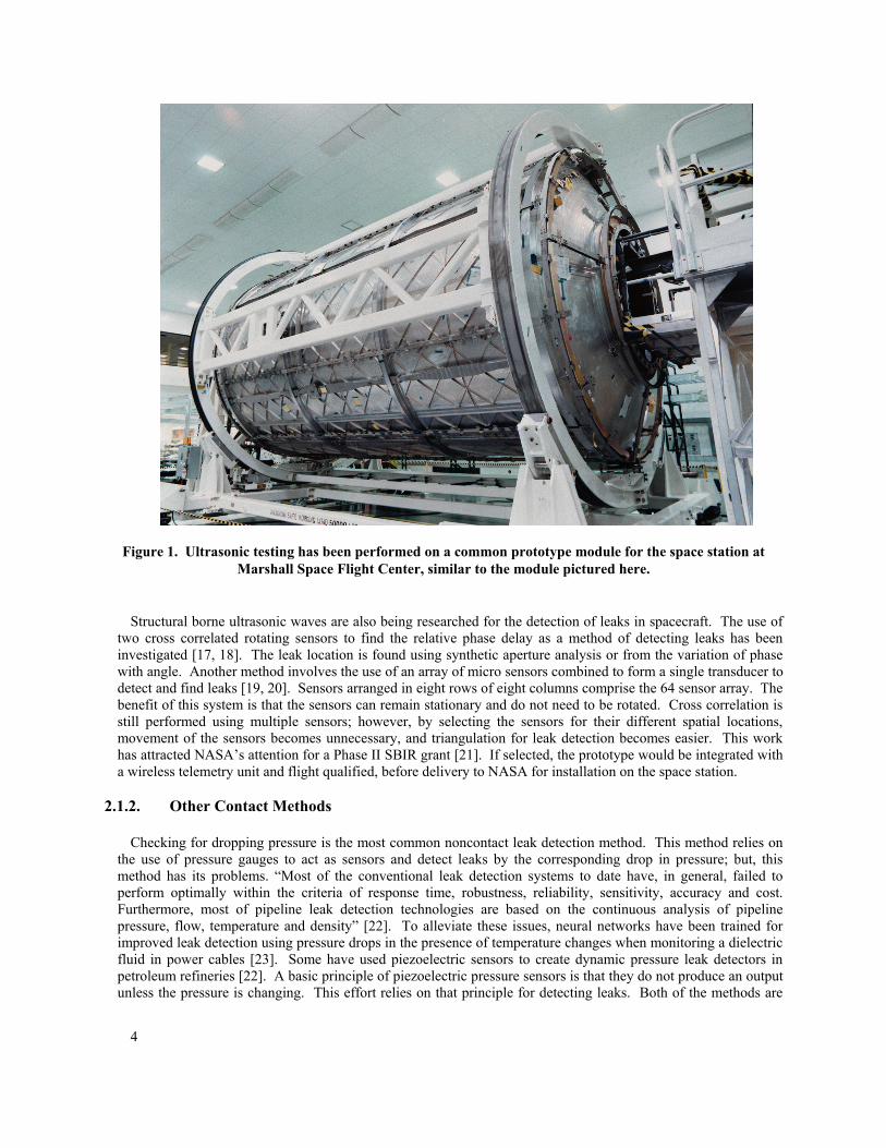
A neural network system was developed and tested on representative panels with waffle grid construction similar to the space station structure [15, 16]. The system was also tested on a prototype of the common module at the Marshall Space Flight Center (Fig. 1.). Two drilled holes in the prototype provided data on two different leak rates for leak location tests. The results showed that RMS amplitude works for leak location on the space station modules.
4
Figure 1. Ultrasonic testing has been performed on a common prototype module for the space station at Marshall Space Flight Center, similar to the module pictured here.
Structural borne ultrasonic waves are also being researched for the detection of leaks in spacecraft. The use of
two cross correlated rotating sensors to find the relative phase delay as a method of detecting leaks has been investigated [17, 18]. The leak location is found using synthetic aperture analysis or from the variation of phase with angle. Another method involves the use of an array of micro sensors combined to form a single transducer to detect and find leaks [19, 20]. Sensors arranged in eight rows of eight columns comprise the 64 sensor array. The benefit of this system is that the sensors can remain stationary and do not need to be rotated. Cross correlation is still performed using multiple sensors; however, by selecting the sensors for their different spatial locations, movement of the sensors becomes unnecessary, and triangulation for leak detection becomes easier. This work has attracted NASA’s attention for a Phase II SBIR grant [21]. If selected, the prototype would be integrated with a wireless telemetry unit and flight qualified, before delivery to NASA for installation on the space station.
2.1.2. Other Contact Methods
Checking for dropping pressure is the most common noncontact leak detection method. This method relies on the use of pressure gauges to act as sensors and detect leaks by the corresponding drop in pressure; but, this method has its problems. “Most of the conventional leak detection systems to date have, in general, failed to perform optimally within the criteria of response time, robustness, reliability, sensitivity, accuracy and cost. Furthermore, most of pipeline leak detection technologies are based on the continuous analysis of pipeline pressure, flow, temperature and density” [22]. To alleviate these issues, neural networks have been trained for improved leak detection using pressure drops in the presence of temperature changes when monitoring a dielectric fluid in power cables [23]. Some have used piezoelectric sensors to create dynamic pressure leak detectors in petroleum refineries [22]. A basic principle of piezoelectric pressure sensors is that they do not produce an output unless the pressure is changing. This effort relies on that principle for detecting leaks. Both of the methods are
5
tailored to systems with high-pressure and may be unsuitable for detecting the lower pressure differentials found in a spacecraft’s atmosphere.
Leak detection of vacuum sealed micro electronic packages has led to the development of a MicroElectroMechanical System (MEMS) Pirani Gauge leak detector [24]. This technology has potential for space applications because it has little mass and uses little power. The micro gauge measures pressure from 10 mTorr to 760 Torr, but requires multiple devices with differing sensitivities to achieve the best resolution across the range of pressures. The devices were custom designed for packaging applications and may need costly redesigns before they are space qualified.
Wireless checking for leaks in water pipes by using accelerometers has been demonstrated [25]. The system is
based on the Intel Mote platform and sampled data at a rate of 600 samples per second. The device could find leaks within 30 cm, and although the system could correctly classify 87% of the leaks, detecting small leaks remained problematic.
The “Worldwide Assessment of Industry Leak Detection Capabilities for Single & Multiphase Pipelines”
suggests the range of leak sizes that can be detected is greatest when employing multiple leak detection methods [26]. Pressure methods quickly detect large leaks. Specialized hardware can detect small leaks but requires more time. Mass balance techniques detect medium flow leaks in a moderate amount of time. A combination of all three techniques would capture most, if not all leaks, in as timely a manner as possible.
2.2. NonContact 2.2.1. Optical Methods
Simple optical methods have been used in an attempt to visually detect and locate leaks from the MIR Spektr module. One technique employed astronauts and cameras on the STS-86 space shuttle mission to identify ice as it vented from the leaking Spektr module [27]. Although ice was seen and photographed, the technique did not lead to successful leak location.
As the Spektr module leaks persisted, another attempt to visually locate the leaks was performed in 1999. STS-
91 carried 30 lbs of a gaseous mixture of nitrogen, Biacetyl, and acetone to the Mir space station. This gas mixture will fluoresce in the presence of sunlight. The gaseous mixture was released into the Spektr module during two separate tries to image the leaks. During the first try the space shuttle was docked, and during the second try the space shuttle was flying around the Mir (approximately 240 feet away). Unfortunately, both tries were unsuccessful, and fluorescing gas plumes were neither seen nor photographed during the attempts [28]. Glare from sunlight, the distance, and lack of sufficient quantities of the tracer gases were given as reasons for the unsuccessful outcome.
Other methods were considered before deciding on the use of fluorescing gases. One idea was to capture the IR
signature of the escaping gases using a special IR camera. Another idea was to use a portable mass spectrometer to detect the escaping tracer gases during an EVA. Both of these ideas needed the development of expensive flight qualified hardware, and for that reason they were both dismissed in favor of the fluorescing gas method.
Active and passive IR imaging of the leaking gases has been explored terrestrially. For active systems, the gas
plume is illuminated by a laser and imaged using a camera [29, 30, 31]. For passive mode systems, an IR camera with narrow spectral filters to detect the thermal emission of the gas plume is used for imaging [32]. Both of these methods have worked in laboratory settings, but each requires tailored hardware and configuration for each gas that it needs to detect. Also, it has not been proven that either method will work, in the case of a gas at atmospheric pressure escaping and dissipating into a vacuum.
6
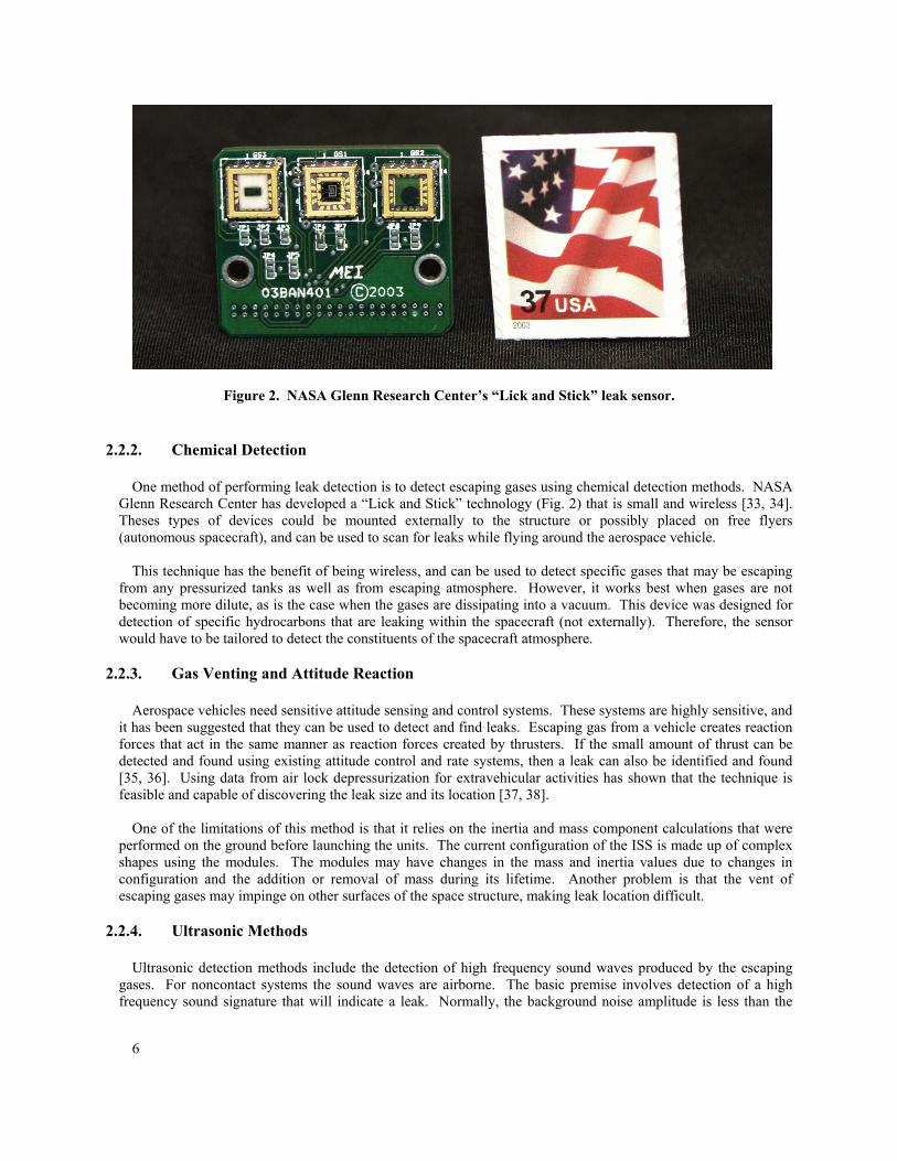
Figure 2. NASA Glenn Research Center’s “Lick and Stick” leak sensor.
2.2.2. Chemical Detection
One method of performing leak detection is to detect escaping gases using chemical detection methods. NASA Glenn Research Center has developed a “Lick and Stick” technology (Fig. 2) that is small and wireless [33, 34]. Theses types of devices could be mounted externally to the structure or possibly placed on free flyers (autonomous spacecraft), and can be used to scan for leaks while flying around the aerospace vehicle.
This technique has the benefit of being wireless, and can be used to detect specific gases that may be escaping
from any pressurized tanks as well as from escaping atmosphere. However, it works best when gases are not becoming more dilute, as is the case when the gases are dissipating into a vacuum. This device was designed for detection of specific hydrocarbons that are leaking within the spacecraft (not externally). Therefore, the sensor would have to be tailored to detect the constituents of the spacecraft atmosphere.
2.2.3. Gas Venting and Attitude Reaction
Aerospace vehicles need sensitive attitude sensing and control systems. These systems are highly sensitive, and it has been suggested that they can be used to detect and find leaks. Escaping gas from a vehicle creates reaction forces that act in the same manner as reaction forces created by thrusters. If the small amount of thrust can be detected and found using existing attitude control and rate systems, then a leak can also be identified and found [35, 36]. Using data from air lock depressurization for extravehicular activities has shown that the technique is feasible and capable of discovering the leak size and its location [37, 38].
One of the limitations of this method is that it relies on the inertia and mass component calculations that were
performed on the ground before launching the units. The current configuration of the ISS is made up of complex shapes using the modules. The modules may have changes in the mass and inertia values due to changes in configuration and the addition or removal of mass during its lifetime. Another problem is that the vent of escaping gases may impinge on other surfaces of the space structure, making leak location difficult.
2.2.4. Ultrasonic Methods
Ultrasonic detection methods include the detection of high frequency sound waves produced by the escaping gases. For noncontact systems the sound waves are airborne. The basic premise involves detection of a high frequency sound signature that will indicate a leak. Normally, the background noise amplitude is less than the
7
leak noise amplitude at the monitored frequencies. Leak localization is performed by using spatial information from the sensors and using time, amplitude, and phase of the signals from each sensor.
The chaotic nature of acoustic sound has been examined in a petroleum refinery. The data was used with the chaos theory to discover the Lorenz attractors, which would enable detection of leaks using airborne ultrasonic waves [39]. Experiments were performed using a silencer nozzle near a high-pressure gas unit in a working refinery in Chiba. The results showed that it is possible to detect gas leaks using the chaos theory in a working refinery.
NASA has a history of working with companies to develop leak detection and location equipment. In 2001, a
CTRL System’s UL101 device was flight qualified and flown on STS-104 mission to the ISS. It was used to find the leak in the ISS air lock during the July mission [40]. The success from the first use of the device led NASA to manifest it on all Shuttle missions beginning in the third quarter of 2003 [41]. The device was used again on board the space station in 2004 with mixed results. The first try did not locate the leak; however, after turning off the equipment in the module, astronauts were able to find the leak. Although not space qualified, another device was developed for use at Kennedy Space Center to detect leaks from the Space Shuttle and launchpad equipment [42]. This device was specifically designed to reflect ultrasonic waves at the tip of the transducer to allow for smaller leaks to be detected.
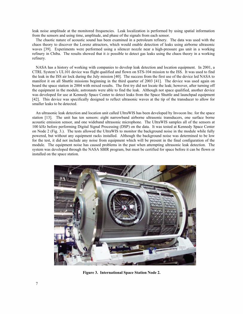
An ultrasonic leak detection and location unit called UltraWIS has been developed by Invocon Inc. for the space
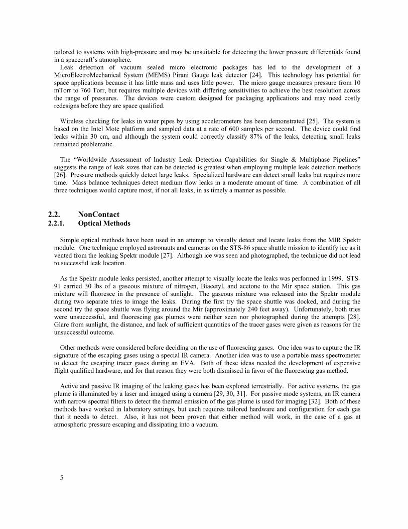
station [13]. The unit has ten sensors: eight narrowband airborne ultrasonic transducers, one surface borne acoustic emission sensor, and one wideband ultrasonic microphone. The UltraWIS samples all of the sensors at 100 kHz before performing Digital Signal Processing (DSP) on the data. It was tested at Kennedy Space Center on Node 2 (Fig. 3.). The tests allowed the UltraWIS to monitor the background noise in the module while fully powered, but without any equipment racks installed. Although the background noise was determined to be low for the test, it did not include any noise from equipment which will be present in the final configuration of the module. The equipment noise has caused problems in the past when attempting ultrasonic leak detection. The system was developed through the NASA SBIR program, but must be certified for space before it can be flown or installed on the space station.
Figure 3. International Space Station Node 2.
8
3. Wireless Sensor Nodes
Wireless sensing is an outcome of research performed at Berkeley University on the Smart Dust program. Current commercial technology centers on the use of a processor with the addition of wireless transceivers. Other features that are sought in a wireless sensor are synchronization, reliability, processing power, DSP, self-diagnosis, and self-identification [43]. The standard term for a wireless node of this type is a “mote.” For a review of the evolution of motes, refer to Polastre [44]. Motes can be divided into three categories by the hardware implementation. The three divisions are microcontroller based motes, microprocessor based motes, and System-on-a-Chip (SoC) technology.
3.1. Microcontroller Based Motes Although Berkeley and Dust Networks Inc. lead this research, several companies have capitalized on their
work. Crossbow is one these companies that has risen to become the largest supplier of motes. Crossbow manufactures microcontroller based motes that are fairly small. They are roughly the size of a half dollar for their Mica2 products. Microcontroller based motes have been very successful in many applications. However, the applications can all be described as very low data rates systems, usually with extremely low duty cycles (since power is the biggest issue for all wireless devices). To make batteries last a reasonable amount of time, extremely low duty cycles must be used. Many NASA applications are found in inaccessible locations where batteries are not a good solution. Also, temperature extremes often exclude the use of batteries. Although energy harvesting has been successfully applied in some applications, the technology has not advanced as quickly as needed. Nor has battery technology advanced. Thus, power remains a major issue.
For most people, Crossbow Technology Inc. comes to mind when considering wireless sensing motes.
Crossbow markets an extremely successful microcontroller line of products. They also manufacture a line of products for aircraft and UAVs, such as the inertial navigation systems [45]. Although these products are certified for aircraft, they do not include wireless functionality. However, the company’s experience in both wireless sensing nodes and aircraft avionics makes them a natural candidate for development of wireless sensor networks for aircraft applications.
Other groups have also developed microcontroller based sensor nodes. The Commonwealth Scientific and
Industrial Research Organisation (CSIRO) in Australia has developed hardware they call “Flecks.” Theses devices incorporate a microcontroller with long-range (500m) RF communications [46]. The Flecks have been used for various sensing applications in a wide variety of environments, from monitoring people in social situations to monitoring livestock in the field. Flecks have also been used to monitor greenhouses, or monitor underwater environments (by using the “Sea Fleck”).
One possible candidate for a wireless leak detection system is the low power, wireless, micro crack sensor,
developed by GE global Research Center [47]. The micro crack sensor uses custom developed hardware to detect acoustic emission signals and “wake up” the microcontroller to take data. This allows the microcontroller to stay in a sleep mode for a longer period of time, thus prolonging the battery life. The system stores data at a high data rate for a very short time before sending the data wirelessly to the control node. Currently, it uses acoustic emission techniques to monitor micro cracks, but it could be modified for ultrasonic acoustic leak detection.
Another system that addresses the high data rates needed for Structural Health Monitoring (SHM) uses a Field
Programmable Gate Array (FPGA) to conserve power while increasing the number of samples per second [48]. The system also uses a discrete analog to digital converter that is much faster than those found integrated into microcontrollers. The system was demonstrated by sampling a 220 kHz signal at 1 Msps, but it is capable of a maximum rate of 10 Msps. The data can then be transmitted to the base node at a rate of 14.4 kbps.
9
3.2. Microprocessor Based Motes To address the needs of complex measurements, greater processing than what is currently available in
microcontrollers needs developing. For that reason, microprocessors have been used to develop motes with a magnitude increase in processing, in comparison to microcontrollers. Microprocessor based motes are being developed for both medical applications and radiation tolerant versions for space applications.
Unfortunately, this processing power comes at the expense of greater power utilization. Power is the biggest
issue that affects all forms of motes for wireless sensing. “For tiny, low power sensors, the most important issue is the power consumption. To make such sensor networks useful, power consumption issues must be addressed. In a word, all protocols and applications for sensor networks must consider the power consumption issue and try their best to minimize power consumption” [49].
The use of a microprocessor instead of a microcontroller increases the choices for operating systems on wireless
sensing platforms. One example is the use of the Linux on Gumstix single board computers [50]. The Gumstix operating frequency runs in the hundreds of megahertz, far above the processing speed of a microcontroller, but at the expense of greater power drain and, consequently, shorter battery lifetimes.
Greenpeak claims to have developed a low power, batteryless, wireless module, that has three times the
communication range of similar products [51]. The module has an interface for connecting energy harvesting power devices for batteryless operation. Like its counterparts, the data rate is 250 kbps. This technology may prove useful for current low data rate applications, and could provide the starting point for developing low power high data rate systems needed for leak detection, as well as other Integrated Vehicle Health Management (IVHM) applications. It should be noted that Greenpeak does not make the energy harvesting module and that others also have interfaces to the third party energy modules.
Even the processor giant, Intel, has entered the arena of wireless sensing by introducing the “Intel Mote
platform” [52, 53]. These devices feature the Intel XScale CPU that includes DSP functionality, RAM, FLASH memory and an 802.15.4 compatible radio. The processor can run from 13 ~ 416 MHz, making it useful for a variety of sensing tasks. Of course, power consumption and clock speeds both increase together.
Very few are working on new hardware for wireless sensing applications; however, a hardware accelerated
implementation of the IEEE 802.15.3 Medium Access Control (MAC) protocol has been developed [54]. This device offloads the computational requirements from the main processor. This allows a public domain processor like LEON-2 to be used for wireless sensor applications such as medical monitoring [55]. If pursued, this technology could be combined with work on a fault tolerant and radiation tolerant LEON-3 FT processor [56, 57]. This processor is being developed for the European Space Agency (ESA) for future space missions.
3.3. System-on-a-Chip (SoC) Based Motes
System-on-a-Chip (SoC) technology is the direct result of the constant trend towards higher integration in
electronic circuits. Integration has several benefits. It reduces the power and increases the speed of operation while increasing the functionality. Custom SoC technology allows designers to tailor the hardware for specific applications. Dust Networks Inc. and Berkeley University have consistently used these techniques to develop the smallest, lowest power hardware as they strive to develop “Smart Dust.” They are targeting a 2mm2 mote-on-a-chip that will include all the functionality of a conventional wireless sensing mote, but will be small enough to be deployed as throw away devices for military applications [58]. Besides miniaturizing hardware for wireless sensing, they have also developed a networking protocol called, “Time Synchronized Mesh Protocol” (TSMP) for their devices [59]. This is an ultralow-power, wireless sensing, network protocol, which is self-organizing, multihop and very reliable in harsh RF environments.
10
4. ISS Application
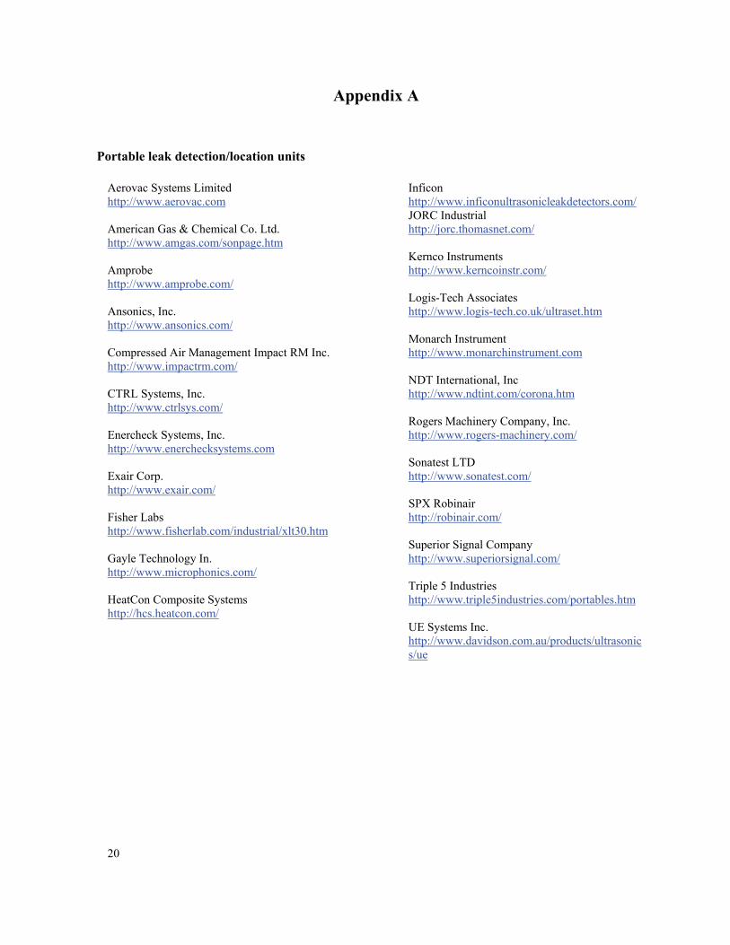
Many of the systems and methods discussed in Sections 2 and 3 are still experimental and are not ready for near term application. The following is a survey of commercially available leak detection and location devices currently being advertised. Thirty-eight companies were identified with a total of 76 products (Table 4.1.). Websites for these companies are listed in Appendix A. The survey was performed to determine the best candidates for solving the issue of leak location on board the ISS.
The survey began with criteria for web searches that produced over 30,000 hits. From this large number of
potential sites, the search criteria were adjusted in order for the researchers to examine only a few hundred websites. Of these websites, 38 companies were identified, returning 76 products that needed to be evaluated in order to determine potential for the application.
In an effort to establish the top twelve candidates to be considered for development of flight certified hardware,
the following scoring system was developed.
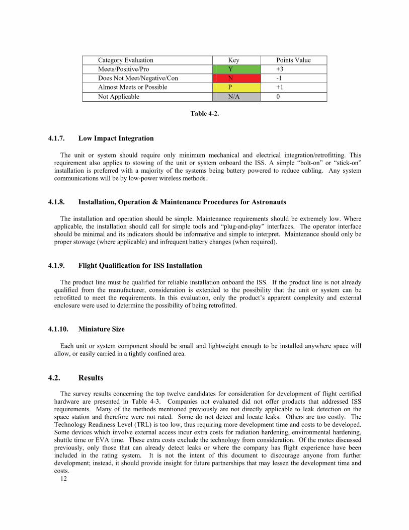
4.1. Scoring System Each requirement is scored using a simple points system. The points are in Table 4-2
4.1.1. Evaluation Categories (Requirements)
Representative off-the-shelf products from various leak detection categories were evaluated based on a general set of minimal requirements. The following subsections describe the general requirements for each unit or system under evaluation.
4.1.2. Detect Leak and Provide its Location
The product line should detect leaks and provide the specific location of the leak source. In the evaluation, the detection and location requirements are separated and weighted to fairly represent the various methods of leak detection.
4.1.3. Complete System Available & Operational
This requirement category shows whether the product line is a complete operational package (Meets), in development (Possible), or a possible candidate to be incorporated into a package (Possible).
4.1.4. Autonomous Operation
Except for startup and routine maintenance, the product line must be capable of operating autonomously without human intervention.
4.1.5. Wireless Communications (Where applicable)
To reduce cabling, the product line should use wireless communications for control, networking, and data acquisition.
11
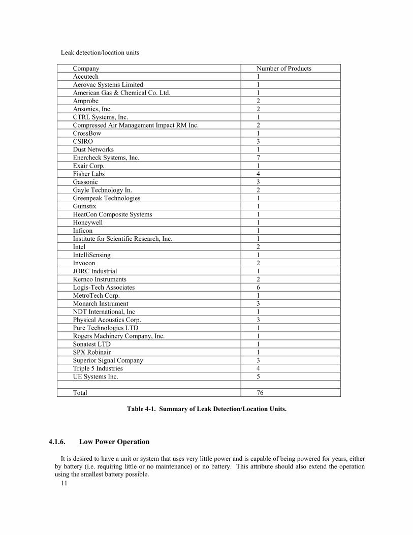
Leak detection/location units
Company Number of Products Accutech 1 Aerovac Systems Limited 1 American Gas & Chemical Co. Ltd. 1 Amprobe 2 Ansonics, Inc. 2 CTRL Systems, Inc. 1 Compressed Air Management Impact RM Inc. 2 CrossBow 1 CSIRO 3 Dust Networks 1 Enercheck Systems, Inc. 7 Exair Corp. 1 Fisher Labs 4 Gassonic 3 Gayle Technology In. 2 Greenpeak Technologies 1 Gumstix 1 HeatCon Composite Systems 1 Honeywell 1 Inficon 1 Institute for Scientific Research, Inc. 1 Intel 2 IntelliSensing 1 Invocon 2 JORC Industrial 1 Kernco Instruments 2 Logis-Tech Associates 6 MetroTech Corp. 1 Monarch Instrument 3 NDT International, Inc 1 Physical Acoustics Corp. 3 Pure Technologies LTD 1 Rogers Machinery Company, Inc. 1 Sonatest LTD 1 SPX Robinair 1 Superior Signal Company 3 Triple 5 Industries 4 UE Systems Inc. 5 Total 76
Table 4-1. Summary of Leak Detection/Location Units.
4.1.6. Low Power Operation
It is desired to have a unit or system that uses very little power and is capable of being powered for years, either by battery (i.e. requiring little or no maintenance) or no battery. This attribute should also extend the operation using the smallest battery possible.
12
Category Evaluation Key Points Value Meets/Positive/Pro Y +3 Does Not Meet/Negative/Con N -1 Almost Meets or Possible P +1 Not Applicable N/A 0
Table 4-2.
4.1.7. Low Impact Integration
The unit or system should require only minimum mechanical and electrical integration/retrofitting. This requirement also applies to stowing of the unit or system onboard the ISS. A simple “bolt-on” or “stick-on” installation is preferred with a majority of the systems being battery powered to reduce cabling. Any system communications will be by low-power wireless methods.
4.1.8. Installation, Operation & Maintenance Procedures for Astronauts
The installation and operation should be simple. Maintenance requirements should be extremely low. Where applicable, the installation should call for simple tools and “plug-and-play” interfaces. The operator interface should be minimal and its indicators should be informative and simple to interpret. Maintenance should only be proper stowage (where applicable) and infrequent battery changes (when required).
4.1.9. Flight Qualification for ISS Installation
The product line must be qualified for reliable installation onboard the ISS. If the product line is not already qualified from the manufacturer, consideration is extended to the possibility that the unit or system can be retrofitted to meet the requirements. In this evaluation, only the product’s apparent complexity and external enclosure were used to determine the possibility of being retrofitted.
4.1.10. Miniature Size
Each unit or system component should be small and lightweight enough to be installed anywhere space will allow, or easily carried in a tightly confined area.
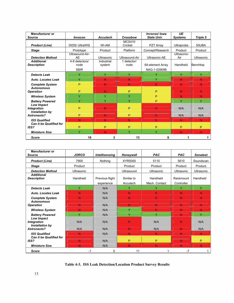
4.2. Results The survey results concerning the top twelve candidates for consideration for development of flight certified
hardware are presented in Table 4-3. Companies not evaluated did not offer products that addressed ISS requirements. Many of the methods mentioned previously are not directly applicable to leak detection on the space station and therefore were not rated. Some do not detect and locate leaks. Others are too costly. The Technology Readiness Level (TRL) is too low, thus requiring more development time and costs to be developed. Some devices which involve external access incur extra costs for radiation hardening, environmental hardening, shuttle time or EVA time. These extra costs exclude the technology from consideration. Of the motes discussed previously, only those that can already detect leaks or where the company has flight experience have been included in the rating system. It is not the intent of this document to discourage anyone from further development; instead, it should provide insight for future partnerships that may lessen the development time and costs.
13
Manufacturer or
Source Invocon Accutech Crossbow Invocon/ Iowa State Univ
UE Systems Triple 5
Product (Line) DIDS/ UltraWIS WI-AM MCS410 Cricket PZT Array Ultraprobe 50UBA
Stage Prototype Product Platform Concept/Research Product Product
Detection Method Ultrasound-Air-
AE Ultrasonic Ultrasound-Air Ultrasonic-AE Ultrasonic-
Air Ultrasonic Additional
Description 4-8 detectors/
node Industrial system
1 detector/ node 64-element Array Handheld
Benchtop
SBIR NAG-1-029098 Detects Leak Y Y Y Y Y Y Auto. Locates Leak Y N N Y N N Complete System P N N N N N Autonomous
Operation P N P P N N Wireless System Y Y Y P N N Battery Powered Y Y Y P Y Y Low Impact
Integration P N P N N/A N/A Installation by
Astronauts? P N P N N/A N/A ISS Qualified N N N N N N Can it be Qualified for
ISS? P P P P P P Miniature Size Y N Y Y N N
Score 19 3 13 9 1 1 Manufacturer or
Source JORCO Intellisensing Honeywell PAC PAC Sonatest
Product (Line) 7900 Nothing XYR5000 5110 5610 Soundscan
Stage Product Product Product Product Product Detection Method Ultrasonic Ultrasound Ultrasonic Ultrasonic Ultrasonic Additional
Description Handheld Previous flight Similar to Handheld Rackmount Handheld experience Accutech Mech. Contact Controller Detects Leak Y N/A Y Y Y Y Auto. Locates Leak N N/A N N N N Complete System N N/A N N N N Autonomous
Operation N N/A N N N N Wireless System N N/A Y N N N Battery Powered Y N/A Y Y N Y Low Impact
Integration N/A N/A N N/A N N/A Installation by
Astronauts? N/A N/A N N/A N N/A ISS Qualified N N/A N N N N Can it be Qualified for
ISS? N N/A P P N P Miniature Size N N/A N N N N
Score -1 0 11 1 -7 1
Table 4-3. ISS Leak Detection/Location Product Survey Results
14
4.2.1. Handheld Units
Handheld ultrasonic units were represented by UE Systems Ultraprobe, Jorco 7900, PAC 5110 and the Sonatest Soundscan. A handheld unit is onboard the ISS to aid in leak detection. Although portable, the handheld units do not address locating the leak source automatically, and each unit requires an operator. Also, airborne systems require a line-of-sight between the source and sensor.
4.2.2. Desktop and Rack-mount Units
Desktop/Rack-mount ultrasonic units were represented by PAC 5610 and the Triple-5 50UBA. These units are designed for a benign environment and only detect the presence of a leak. Similar to the handheld units, these types do not address pinpointing the location of the leak, and each unit requires an operator.
4.2.3. Industrial Monitoring Systems
The industrial monitoring systems are used to monitor process equipment in harsh environments. These systems utilize a separate master controller with a network of various sensor modules. Ultrasonic airborne leak detection sensors are available. These sensor modules are mainly designed to detect leaks in the general vicinity of the sensor installation. No specific leak source location capability is included. Another drawback is the sensor module’s size and weight. Designed to withstand punishing industrial environments, the modules tend to be heavy, bulky, and require heavy duty mounting.
4.2.4. Other Platforms & Prototypes
The PZT Array from Invocon/Iowa State University [17-18] is a research prototype, which addresses detection and location. Its development is being supported by NASA under their STTR program. Because of the inherent complexity in integration, it falls short as a system ready for immediate application. A video demonstration of this promising system is available on line at:
http://home.eng.iastate.edu/~rreusser/leakdetection_h2641q.mov (for Macintosh) and http://home.eng.iastate.edu/~rreusser/leak3.mpg (for Windows). As for the Crossbow MCS410 Cricket product, the unit scores high in all but the important categories of
detection/location. The Cricket was included in the evaluation to represent a product that could possibly be used as a baseline design for a leak detection/location module or system.
.
4.2.5. Leading Candidate System
As is often the case when performing trade-offs between existing systems, an optimal solution does not exist. The number one candidate was chosen primarily because it will have a shorter development time than its counterparts. The Distributed Impact Detection System (DIDS), from Invocon [13], is a more recently developed wireless system that is a next generation ultrasonic system after the UltraWIS. DIDS has advantages in its leak detecting/locating possibilities, small size, low integration resource requirements, and flexibility. Invocon also has experience in developing and building devices for NASA missions; hence, it is likely that the DIDS can be flight qualified.
As discussed earlier, DIDS will require additional development and refinement before being considered as
foolproof. To operate reliably, the system will need to address background equipment noise and multiple receptions of the same leak source.
15
5. Future Directions
The Distributed Impact Detection System (DIDS) was developed under a NASA Phase 2 Small Business Innovation Research (SBIR) grant to create the DIDS [60]. This system is a wireless acoustic emission system for monitoring spacecraft for MMOD impacts. The system addresses some of the issues for structural borne acoustic emissions. Although the system does not address airborne signals, it could easily be adapted to mimic the configuration of the UltraWIS. The system will also need to be flight certified before it can be flown.
Currently, a drop in pressure gives the best indication of a leak on the space station. Handheld leak location
hardware is presently aboard the space station; however, in the past, the hardware has had difficulty detecting small leaks while equipment was running. Closing hatches remains the best way to discover which module is leaking; developing new hardware will improve this situation.
The hardware developed in the future must be more sensitive. Increasing the data transmission rate permits
more sensors and higher bandwidth (for those sensors). An increased sampling rate that covers a bandwidth of at least 400 KHz per sensor enables acoustic emission leak detection techniques. Better synchronization between channels allows for more accurate phase and time of flight measurements. There is always a trade off between specificity and sensitivity for leak detection systems. The hardware should be designed with this trade-off in mind, and at the same time, attempt to be flexible in order to handle either case, when required by a new situation. For keeping down the costs of retrofit devices on the space station, wireless systems are more appealing than their wired counterparts. Also, hardware standardization is preferable, because it makes the hardware useful in other applications.
Besides hardware, new algorithms that decrease the false positive and false negative rates are desired. Software
that improves the accuracy of the leak detection (while reducing the time for leak detection) is also sought after. Naturally, the algorithms will need to be efficient in using the resources of both CPU cycles and memory usage. This will keep the weight and power at a minimum. Autonomous programming techniques are needed to lower the burden on astronauts, by reducing the complexity of the information that is presented to them. They will need answers, not raw data. Artificial intelligence techniques such as neural networks, fuzzy logic, and genetic algorithms may play a role in producing these answers. The new software should be able to detect small leaks, as well as assess the extent of the damage while locating the leak. The software systems should be flexible, reconfigurable, and reprogrammable. This will allow future algorithm developers to upgrade the software after it is in place. Due to the crew’s high workload, they prefer to not have the extra responsibility of dealing with upgrades and computer software maintenance. The ground controllers should handle that task remotely. Of course, following best practices, standards, and developing reusable code are always encouraged.
As mentioned earlier, power is the biggest issue for these systems. Low power designs for each element will
increase battery life. This includes the hardware, software, and RF systems. Each piece must do its part to keep the power consumption at a minimum. For applications like structure borne leak detection, it is preferable to have passive sensors attached to structure. These can use energy harvesting, scavenging, and RF techniques to power themselves rather than rely on astronaut time to change batteries. Passive RFID tags and Surface Acoustic Wave (SAW) sensors are both being investigated by NASA as potential solutions to the power problem for wireless sensor systems.
16
Conclusions
Various methods for leak detection and location have been examined. Also, the requirements have been presented for leak detection and leak location on board the ISS. Commercial leak detection devices have been surveyed and the candidate that currently best suits the requirements has been identified. Although the candidate is more developed than its counterparts, it will require flight certification before it can be flown.
Even though a candidate was chosen, future aerospace vehicles will still require the detection of smaller leaks,
faster response, and more accurate leak location without false positives and false negatives. The hardware will need to have higher data rates and consume less power, while also fitting in a smaller volume. Therefore, opportunities still exist for new systems to be developed.
References
1. NASA, "NASA’s Implementation Plan for International Space Station Continuing Flight" NASA February
15, 2005, Available: http://www.nasa.gov/pdf/110883main_Station_CFT_Rev2.pdf 2. J. Holliman, “Leak in Mir may have been Located”, in CNN Interactive Online, October, 3, 1997,
Available: http://cnn.websites-blog.com/TECH/9710/03/mir/index.html 3. C. V. D. Berg, "6th Spacewalk (EVA) Crew 24th Main Expedition MIR," in MirNews, vol. 402, January 8,
1998, Available: http://www.satobs.org/mir1.html. 4. Z. Anatoly, “Mir Leaking Air”, in Space.com News, October, 14, 1999, Available:
http://www.space.com/news/spacestation/mir_leak_000420.html 5. Z. Anatoly, “Mir Cosmonauts Plug Leak”, in Space.com News, April, 20, 2000, Available:
http://www.space.com/news/spacestation/mir_leak_000420.html 6. A. Barnett, “Space Station's New Air Lock Tweaked”, in CNN.com/Space, July 16, 2001, Available:
http://archives.cnn.com/2001/TECH/space/07/16/atlantis.alpha/index.html 7. M. Carreau, "Leak will Delay Shuttle's Return Home," in Houston Chronicle, Houston, Texas: CNN.com,
2001, Available: http://www.chron.com/disp/story.mpl/space/iss/969156.html. 8. NASA, International Space Station Status Reports, vol. ISS04-3, January 12, 2004, Available:
http://www.spaceflight.nasa.gov/spacenews/reports/issreports/2004/index.html 9. D. K. Lemon, M. A. Friesel, J. W. Griffin, J. R. Skorpik, C. L. Shepard, Z. I. Antoniak, and R. J. Kurtz,
“Technology Evaluation for Space Station Atmospheric Leakage”, OSTI ID: 7259819; DE90007844, Report Number PNL-7269, Technical Report, DOE Project Research, Pacific Northwest Lab., Richland, WA (USA), February 01, 1990, p. 110, Available: http://www.osti.gov/energycitations/product.biblio.jsp?osti_id=7259819.
10. R. G. Sellar and W. Danli, “Assessment of Remote Sensing Technologies for Location of Hydrogen and Helium Leaks”, NASA Technical Report, Phase 1 Final Report, Document #20040040297, February 28, 2000, p. 39, Available: http://ntrs.nasa.gov/.
11. J. Brusey, A. Thorne, “Aero-ID Sensor Integration: Scope of Work”, AEROID-CAM-003, Auto-ID Labs, University of Cambridge, Cambridge, UK, February 1, 2006, Available: http://aero-id.org/mediawiki/img_auth.php/a/a4/Aeroid-cam-003-sensor.pdf.
12. Alaska Department of Environmental Conservation (ADEC), “Technical Review of Leak Detection Technologies I”, Anchorage, Alaska October 26, 1999, p. 31. Available: http://www.state.ak.us/dec/spar/ipp/docs/ldetect1.pdf
13. K. D. Champaigne and J. Sumners, “Wireless Impact and Leak Detection and Location Systems for the ISS and Shuttle Wing Leading Edge”, In Aerospace Conference, IEEE, March 2005, p. 1-8.
14. W. H. Prosser, M. R. Gorman, E. I. Madaras, “Acoustic Emission Detection of Impact Damage on Space Shuttle Structures”, In 17th International Acoustic Emission Symposium, Tokyo; Japan, 9-11 Nov. 2004, p. 8.
17
15. M. A. Friesel R.S. Barga, J. F. Dawson P.H. Hutton, R. J. Kurtz D.K. Lemon, “Acoustic Emissions Applications on the NASA Space Station”, in Review of Progress in Quantitive NDE Conference, Brunswick Maine, July 27 ~ Aug. 2 1991, vol. 11A, pp. 725-732.
16. R. S. Barga, M. A. Friesel, and J. L. Meador, "Source Location of Acoustic Emissions from Atmospheric Leakage using Neural Networks", In Application of Neural Networks II, Orlando, Florida, April 1991, p. 602-611.
17. S. D. Holland, R. Roberts, D. E. Chimenti, and M. Strei, “Two-Sensor Ultrasonic Spacecraft Leak Detection Using Structure-Borne Noise”, Acoustics Research Letters Online, April 2005, vol. 6, iss. 2, pp. 63-105.
18. S. D. Holland, R. Roberts, D. E. Chimenti, and M. Strei, “Leak Detection in Spacecraft Using Structure-Borne Noise with Distributed Sensors”, Applied Physics Letters, April 25, 2005, vol. 86, pp. 1-3.
19. S. D. Holland, R. Roberts, D. E. Chimenti, and J. H. Song, “An Ultrasonic Array Sensor for Spacecraft Leak Direction Finding”, Ultrasonics, 2006, vol. 45, p 121-126.
20. S. D. Holland, J.-H. Song, D. E. Chimenti, and R. Roberts, “Leak Detection in Spacecraft Using a 64-Element Multiplexed Passive Array to Monitor Structure-Borne Noise”, in Quantitative Nondestructive Evaluation, AIP Conference Proceedings, 2006, vol. 820, pp. 885-891.
21. B. Christensen, "NASA's New Spacecraft Air Leak Sensor" in Technovelgy.com, Available: www.space.com, 2007.
22. W. Lin and X. Zhang, “A Novel Approach for Dynamic Pressure Transducer Based Pipeline Leak Detection”, In Intelligent Control and Automation, 2006, WCICA 2006, The Sixth World Congress on, vol. 2, June 21-23, 2006, pp. 5299-5303.
23. W. Tylman, G. J. Anders, and R. Ghafurian, “Novel Leak Detection System For Pipe Type Cable Installations”, Power Delivery, IEEE Transactions on, vol. 21, iss. 3, July 2006, pp. 1028-1034.
24. B. H. Stark, C. Junseok, A. Kuo, A. Oliver, and N. Khalil, “A High-Performance Surface-Micromachined Pirani Gauge in SUMMIT V”, In Micro Electro Mechanical Systems, MEMS 2005, 18th IEEE International Conference on, January 30 – February 3 2005, pp. 295-298.
25. I. Stoianov, L. Nachman, S. Madden, and T. Tokmouline, “PIPENET: A Wireless Sensor Network for Pipeline Monitoring”. In 6th international Conference on Information Processing in Sensor Networks, Cambridge, Massachusetts, April 25 - 27, 2007, pp. 264-273.
26. S. L. Scott and M. A. Barrufet, “Worldwide Assessment of Industry Leak Detection Capabilities for Single & Multiphase Pipelines”, Prepared for the Minerals Management Service, US DOI, Offshore Technology Research Center, OTRC Library Number: 8/03A120, August 6, 2003. Available: http://otrc.tamu.edu/Pages/Leak%20Detection%20-%20Scott.pdf
27. M. T. Gaunce and D. R. Thompson, "Mir Photo/TV Survey (DTO-1118): STS-86 Mission Report" JSC-28194, March 4, 1998, p. 18-19.
28. J. C. Graf, C. Kittrell, and S. Arepalli, “Mir Leak Detection Using Fluorescent Tracer Gases”, in International Conference On Environmental Systems, July 12-15, 1999, Denver, CO, p. 11.
29. R. Pride, J. Hodgkinson, M. Padget, B. Van Well, R. Strzoda, C. T. Siemens, and G. Munich, “Implementation of Optical Technologies for Portable Gas Leak Detection“, in International Gas Research Conference, Vancouver, B. C., Canada, November 1-4, 2004, p. 20, Available: http://www.physics.gla.ac.uk/Optics/projects/VOGUE/links/Vogue_IGRC_2004_final_Pride_v3.pdf
30. G. Gibson, B. Van Well, J. Hodgkinson, R. Pride, R. Strzoda, S. Murray, S. Bishton, and M. Padgett, “Imaging of Methane Gas Using a Scanning, Open-Path Laser System”, New Journal of Physics, vol .8, 2006, p.26.
31. J. Hodgkinson and R. D. Pride, “Gas Leak Imaging”, Business Briefing: Exploration & Production: The Oil & Gas Review, iss. 2, 2005, pp 47-50.
32. S.-A. Ljungberg, T. J. Kulp, and T. G. McRae, "State-of the-Art and Future Plans for IR Imaging of Gaseous Fugitive Emission," In Thermosense XIX, R.N. Wurzbach, D.D. Burleigh, eds., Proceedings SPIE 3056, April 1997, pp. 2-19.
33. G. W. Hunter, J. C. Xu, P. G. Neudeck, D. B. Makel, B. Ward, and C. C. Liu, “Intelligent Chemical Sensor Systems for in-Space Safety Applications”, in 42nd AIAA/ASME/SAE/ASEE Joint Propulsion Conference, July 9 – 12, 2006, Sacramento, CA, AIAA 2006-4356, p. 12.
34. G. W. Hunter, J. C. Xu, C. C. Liu, and D. B. Makel, “Microfabricated Chemical Sensors for Aerospace Applications”, in The MEMS Handbook. Mohamed Gad-el-Hak, ed., Second edition, Chapter 11,CRC Press, Boca Raton, FL, 2005.
18
35. J.-W. Kim, J. L. Crassidis, S. R. Vadali, and A. L. Dershowitz, “International Space Station Leak Localization Using Attitude Response Data”, AIAA Journal of Guidance, Control, and Dynamics, vol. 29, no. 5, September-October 2006, pp. 1041-1050.
36. J.-W. Kim, J. L. Crassidis, S. R. Vadali, and A. L. Dershowitz, “International Space Station Leak Localization Using Vent Torque Estimation,” in 55th International Astronautical Conference, Vancouver, B. C., Oct. 2004, IAC-04-A.4.10.
37. J.-W. Kim, J. L. Crassidis, S. R. Vadali, and A. L. Dershowitz, “International Space Station Leak Localization Using Attitude Disturbance Estimation,” IEEE Aerospace Conference, Big Sky, MT CA, March 2003, IEEEAC Paper #1391, pp. 3475-3494.
38. J.-W. Kim, J. L. Crassidis, S. R. Vadali, and A. L. Dershowitz, “ISS Leak Localization Using Attitude Response,” AIAA Guidance, Navigation, and Control Conference, Montreal, CA, August 2001, AIAA Paper #01-4272.
39. T. Tani, T. Nagasako, Y. Fujimoto, T. Iokibe, and T. Yamaguchi, “Chaos Information Criteria to Detect High-pressure Gas Leak in Petroleum Refining Plant”, in SICE-ICASE, 2006, International Joint Conference, October 18-21 2006, pp. 5415- 5418.
40. G. Studor, "Ultrasonic Detectors in Space," in CTRL Systems, Inc., 2002, p. 3. 41. A. Hoover, "Maryland Company Expanding Technology in Space - NASA Won't Leave Earth Without the
CTRL UL101," in CTRL Systems, Inc., 2002, p.1. 42. NASA, "Low Level Leaks," Spinoff 1998, NASA, page 96. 43. F. L. Lewis, “Wireless Sensor Networks”, in Smart Environments: Technology, Protocols and
Applications, Cook, D. J., Das, S. K., Ed., Hoboken, NJ, John Wiley and Sons, 2005, pp. 13-46. 44. J. Polastre, R. Szewczyk, C. Sharp, and D. Culler, “The Mote Revolution: Low Power Wireless Sensor
Network Devices” In Hot Chips 16: A Symposium on High Performance Chips, August 22-24, 2004. 45. J. S. Jang and D. Liccardo, “Automation of Small UAVs Using a Low Cost MEMS Sensor and Embedded
Computing Platform,” in 25th Digital Avionics Systems Conference, 2006 IEEE/AIAA, October 2006, pp. 1-9.
46. P. Corke, S. Sen, P. Sikka, P. Valencia, and T. Wark, “Wireless Sensor Network: Two-Year Progress Report”, Queensland Centre for Advanced Technologies, CSIRO, Pullenvale, Australia, Aug 24, 2006, p. 38, Available: http://www.csiro.au/resources/pfik.html.
47. J. Li, Y. Plotnikov, and W. W. Lin, "A Low-Power Wireless Sensor Network for Monitoring the Microcrack Initiations in Aerospace Composites," in Review of Progress in Quantitive NDE Conference, Golden, Colorado, 2007, p. 9.
48. Liu, F. G. Yuan, and F. Zhang, “Development of Wireless Smart Sensor for Structural Health Monitoring”, in Smart Structures and Materials 2005 - Sensors and Smart Structures Technologies for Civil, Mechanical, and Aerospace Systems, 2005, vol. 5765, p176-186.
49. Ahmed, S., Eskicioglu, M. R., “Current Researches on Sensor Networks” Telecommunication Research Labs, , Winnipeg, Manitoba, Canada, Technical Report TR-01-06/04, May 30, 2004, p. 77.
50. R. Kwan, "Computer Systems," Aerospace America, vol. 43, pp. 46-47, December 2005 2005. 51. GreenPeak Technologies, “Lime Module Series CM-08”, Utrecht, The Netherlands, Product sheet, p. 2,
Available: http://www.greenpeak.com/Product/Modules.html. 52. R. M. Kling, "Intel Motes: Advanced Sensor Network Platforms and Applications," in Microwave
Symposium Digest, 2005, IEEE MTT-S International, 2005, pp. 365-368 53. L. Nachman, R. Kling, R. Adler, J. Huang, and V. Hummel, "The Intel© Mote Platform: a Bluetooth-Based
Sensor Network for Industrial Monitoring," in Information Processing in Sensor Networks, 2005. IPSN 2005. Fourth International Symposium on, 2005, pp. 437-442.
54. E. J. P. Dietterle D., Kraemer R., “A Hardware Accelerated Implementation of the IEEE 802.15.3 MAC”, in First International Conference on Wireless Sensor and Actor Networks, (WSAN 2007), Albacete, Spain, September 24-26, 2007, pp. 217-228.
55. D. Dietterle, J. P. Ebert, G. Wagenknecht, and R. Kraemer, “A Wireless Communication Platform for Long-Term Health Monitoring”, in Pervasive Computing and Communications Workshops, PerCom Workshops, Fourth Annual IEEE International Conference on, March 13-17, 2006, p. 5.
56. IHP, Annual Report 2006, “Innovations for High Performance Microelectronics”, Frankfurt, Germany, 2006, Available: http://www.ihp-ffo.de/55.0.html.
57. Z. Stamenkovic, C. Wolf, G. Schoof, and J. Gaisler, “An Implementation Study on Fault Tolerant LEON-3 Processor System”, in 7th IP-Based System-on-Chip Design Conference, Grenoble France, 2006, pp. 23-26.
19
58. Cook, B.W.; Lanzisera, S.; Pister, K.S.J., “SoC Issues for RF Smart Dust”, Proceedings of the IEEE, Volume 94, Issue 6, June 2006, pp. 1177 – 1196.
59. Dust Networks, Inc., “Technical Overview of Time Synchronized Mesh Protocol (TSMP)”, Whitepaper, Dust Networks, Hayward, CA, Available: http://www.dustnetworks.com/technology/, p. 18.
60. K. D. Champaigne and J. Sumners, “Low-power Electronics for Distributed Impact Detection and Piezoelectric Sensor Applications”, in Aerospace Conference, IEEE, March 3-10, 2007, pp. 1-8.
20
Appendix A
Portable leak detection/location units Aerovac Systems Limited http://www.aerovac.com American Gas & Chemical Co. Ltd. http://www.amgas.com/sonpage.htm Amprobe http://www.amprobe.com/ Ansonics, Inc. http://www.ansonics.com/ Compressed Air Management Impact RM Inc. http://www.impactrm.com/ CTRL Systems, Inc. http://www.ctrlsys.com/ Enercheck Systems, Inc. http://www.enerchecksystems.com Exair Corp. http://www.exair.com/ Fisher Labs http://www.fisherlab.com/industrial/xlt30.htm Gayle Technology In. http://www.microphonics.com/ HeatCon Composite Systems http://hcs.heatcon.com/
Inficon http://www.inficonultrasonicleakdetectors.com/ JORC Industrial http://jorc.thomasnet.com/ Kernco Instruments http://www.kerncoinstr.com/ Logis-Tech Associates http://www.logis-tech.co.uk/ultraset.htm Monarch Instrument http://www.monarchinstrument.com NDT International, Inc http://www.ndtint.com/corona.htm Rogers Machinery Company, Inc. http://www.rogers-machinery.com/ Sonatest LTD http://www.sonatest.com/ SPX Robinair http://robinair.com/ Superior Signal Company http://www.superiorsignal.com/ Triple 5 Industries http://www.triple5industries.com/portables.htm UE Systems Inc. http://www.davidson.com.au/products/ultrasonics/ue
21
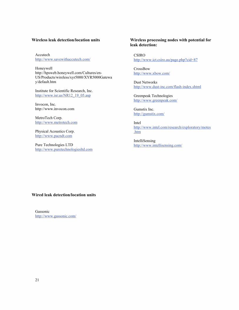
Wireless leak detection/location units Accutech http://www.savewithaccutech.com/ Honeywell http://hpsweb.honeywell.com/Cultures/en-US/Products/wireless/xyr5000/XYR5000Gateway/default.htm Institute for Scientific Research, Inc. http://www.isr.us/NR12_19_05.asp Invocon, Inc. http://www.invocon.com MetroTech Corp. http://www.metrotech.com Physical Acoustics Corp. http://www.pacndt.com Pure Technologies LTD http://www.puretechnologiesltd.com
Wired leak detection/location units
Gassonic http://www.gassonic.com/
Wireless processing nodes with potential for leak detection:
CSIRO http://www.ict.csiro.au/page.php?cid=87 CrossBow http://www.xbow.com/ Dust Networks http://www.dust-inc.com/flash-index.shtml Greenpeak Technologies http://www.greenpeak.com/ Gumstix Inc. http://gumstix.com/ Intel http://www.intel.com/research/exploratory/motes.htm IntelliSensing http://www.intellisensing.com/
REPORT DOCUMENTATION PAGE Form ApprovedOMB No. 0704-0188
2. REPORT TYPE Technical Memorandum
4. TITLE AND SUBTITLELeak Detection and Location Technology Assessment for Aerospace Applications
5a. CONTRACT NUMBER
6. AUTHOR(S)
Wilson, William C.; Coffey, Neil C.; and Madaras, Eric I.
7. PERFORMING ORGANIZATION NAME(S) AND ADDRESS(ES)NASA Langley Research Center Hampton, VA 23681-2199
9. SPONSORING/MONITORING AGENCY NAME(S) AND ADDRESS(ES)National Aeronautics and Space AdministrationWashington, DC 20546-0001
8. PERFORMING ORGANIZATION REPORT NUMBER
L-19515
10. SPONSOR/MONITOR'S ACRONYM(S)
NASA
13. SUPPLEMENTARY NOTES
12. DISTRIBUTION/AVAILABILITY STATEMENTUnclassified - UnlimitedSubject Category 15Availability: NASA CASI (301) 621-0390
19a. NAME OF RESPONSIBLE PERSON
STI Help Desk (email: [email protected])
14. ABSTRACT
Micro Meteoroid and Orbital Debris (MMOD) and other impacts can cause leaks in the International Space Station and other aerospace vehicles. The early detection and location of leaks is paramount to astronaut safety. Therefore this document surveys the state of the art in leak detection and location technology for aerospace vehicles.
15. SUBJECT TERMSDebris; Leak detection; Micro Meteoroid; Motes; Ultrasonic
18. NUMBER OF PAGES
2719b. TELEPHONE NUMBER (Include area code)
(301) 621-0390
a. REPORT
U
c. THIS PAGE
U
b. ABSTRACT
U
17. LIMITATION OF ABSTRACT
UU
Prescribed by ANSI Std. Z39.18Standard Form 298 (Rev. 8-98)
3. DATES COVERED (From - To)
5b. GRANT NUMBER
5c. PROGRAM ELEMENT NUMBER
5d. PROJECT NUMBER
5e. TASK NUMBER
5f. WORK UNIT NUMBER
401769.06.03.04.12
11. SPONSOR/MONITOR'S REPORT NUMBER(S)
NASA/TM-2008-215347
16. SECURITY CLASSIFICATION OF:
The public reporting burden for this collection of information is estimated to average 1 hour per response, including the time for reviewing instructions, searching existing data sources, gathering and maintaining the data needed, and completing and reviewing the collection of information. Send comments regarding this burden estimate or any other aspect of this collection of information, including suggestions for reducing this burden, to Department of Defense, Washington Headquarters Services, Directorate for Information Operations and Reports (0704-0188), 1215 Jefferson Davis Highway, Suite 1204, Arlington, VA 22202-4302. Respondents should be aware that notwithstanding any other provision of law, no person shall be subject to any penalty for failing to comply with a collection of information if it does not display a currently valid OMB control number.PLEASE DO NOT RETURN YOUR FORM TO THE ABOVE ADDRESS.
1. REPORT DATE (DD-MM-YYYY)09 - 200801-