Reciprocating Compressors for Petroleum, Chemical, and Gas...
208
Reciprocating Compressors for Petroleum, Chemical, and Gas Industry Services API STANDARD 618 FIFTH EDITION, DECEMBER 2007 ERRATA 1: NOVEMBER 2009 --``,,,``,,`````,``,,,,,,,`,,`,,-`-`,,`,,`,`,,`---
Transcript of Reciprocating Compressors for Petroleum, Chemical, and Gas...
Reciprocating Compressors forPetroleum, Chemical, and GasIndustry Services
API STANDARD 618FIFTH EDITION, DECEMBER 2007
ERRATA 1: NOVEMBER 2009
--``,,,``,,`````,``,,,,,,,`,,`,,-`-`,,`,,`,`,,`---

--``,,,``,,`````,``,,,,,,,`,,`,,-`-`,,`,,`,`,,`---

Reciprocating Compressors forPetroleum, Chemical, and GasIndustry Services
Downstream Segment
API STANDARD 618FIFTH EDITION, DECEMBER 2007
ERRATA 1: NOVEMBER 2009
--``,,,``,,`````,``,,,,,,,`,,`,,-`-`,,`,,`,`,,`---

Special Notes
API publications necessarily address problems of a general nature. With respect to particular circumstances, local,state, and federal laws and regulations should be reviewed.
Neither API nor any of API's employees, subcontractors, consultants, committees, or other assignees make anywarranty or representation, either express or implied, with respect to the accuracy, completeness, or usefulness of theinformation contained herein, or assume any liability or responsibility for any use, or the results of such use, of anyinformation or process disclosed in this publication. Neither API nor any of API's employees, subcontractors,consultants, or other assignees represent that use of this publication would not infringe upon privately owned rights.
API publications may be used by anyone desiring to do so. Every effort has been made by the Institute to assure theaccuracy and reliability of the data contained in them; however, the Institute makes no representation, warranty, orguarantee in connection with this publication and hereby expressly disclaims any liability or responsibility for loss ordamage resulting from its use or for the violation of any authorities having jurisdiction with which this publication mayconflict.
API publications are published to facilitate the broad availability of proven, sound engineering and operating practices.These publications are not intended to obviate the need for applying sound engineering judgment regarding whenand where these publications should be utilized. The formulation and publication of API publications is not intended inany way to inhibit anyone from using any other practices.
Any manufacturer marking equipment or materials in conformance with the marking requirements of an API standardis solely responsible for complying with all the applicable requirements of that standard. API does not represent, war-rant, or guarantee that such products do in fact conform to the applicable API standard.
All rights reserved. No part of this work may be reproduced, stored in a retrieval system, or transmitted by any means, electronic, mechanical, photocopying, recording, or otherwise, without prior written permission from the publisher. Contact the Publisher, API
Publishing Services, 1220 L Street, N.W., Washington, D.C. 20005.
Copyright © 2007 American Petroleum Institute
--``,,,``,,`````,``,,,,,,,`,,`,,-`-`,,`,,`,`,,`---

Foreword
Nothing contained in any API publication is to be construed as granting any right, by implication or otherwise, for themanufacture, sale, or use of any method, apparatus, or product covered by letters patent. Neither should anythingcontained in the publication be construed as insuring anyone against liability for infringement of letters patent.
Shall: As used in a standard, “shall” denotes a minimum requirement in order to conform to the specification.
Should: As used in a standard, “should” denotes a recommendation or that which is advised but not required in orderto conform to the specification.
Portions of this publication have been changed from the previous edition. The locations of changes have beenmarked with a bar in the margin, as shown to the left of this paragraph. The bar notations in the margins are providedas an aid to users, but API makes no warranty as to the accuracy of such bar notations.
This document was produced under API standardization procedures that ensure appropriate notification andparticipation in the developmental process and is designated as an API standard. Questions concerning theinterpretation of the content of this publication or comments and questions concerning the procedures under whichthis publication was developed should be directed in writing to the Director of Standards, American PetroleumInstitute, 1220 L Street, N.W., Washington, D.C. 20005. Requests for permission to reproduce or translate all or anypart of the material published herein should also be addressed to the director.
Generally, API standards are reviewed and revised, reaffirmed, or withdrawn at least every five years. A one-timeextension of up to two years may be added to this review cycle. Status of the publication can be ascertained from theAPI Standards Department, telephone (202) 682-8000. A catalog of API publications and materials is publishedannually and updated quarterly by API, 1220 L Street, N.W., Washington, D.C. 20005.
Suggested revisions are invited and should be submitted to the Standards Department, API, 1220 L Street, NW,Washington, D.C. 20005, [email protected].
iii--``,,,``,,`````,``,,,,,,,`,,`,,-`-`,,`,,`,`,,`---

--``,,,``,,`````,``,,,,,,,`,,`,,-`-`,,`,,`,`,,`---

Contents
Page
--``,,,``,,`````,``,,,,,,,`,,`,,-`-`,,`,,`,`,,`---
v
1 Scope. . . . . . . . . . . . . . . . . . . . . . . . . . . . . . . . . . . . . . . . . . . . . . . . . . . . . . . . . . . . . . . . . . . . . . . . . . . . . . . . . . . 1
2 Normative References. . . . . . . . . . . . . . . . . . . . . . . . . . . . . . . . . . . . . . . . . . . . . . . . . . . . . . . . . . . . . . . . . . . . . 1
3 Definitions of Terms . . . . . . . . . . . . . . . . . . . . . . . . . . . . . . . . . . . . . . . . . . . . . . . . . . . . . . . . . . . . . . . . . . . . . . 4
4 General . . . . . . . . . . . . . . . . . . . . . . . . . . . . . . . . . . . . . . . . . . . . . . . . . . . . . . . . . . . . . . . . . . . . . . . . . . . . . . . . . 84.1 Unit Responsibility. . . . . . . . . . . . . . . . . . . . . . . . . . . . . . . . . . . . . . . . . . . . . . . . . . . . . . . . . . . . . . . . . . . . . . . . 84.2 Unit Conversion . . . . . . . . . . . . . . . . . . . . . . . . . . . . . . . . . . . . . . . . . . . . . . . . . . . . . . . . . . . . . . . . . . . . . . . . . . 84.3 Nomenclature . . . . . . . . . . . . . . . . . . . . . . . . . . . . . . . . . . . . . . . . . . . . . . . . . . . . . . . . . . . . . . . . . . . . . . . . . . . . 8
5 Requirements . . . . . . . . . . . . . . . . . . . . . . . . . . . . . . . . . . . . . . . . . . . . . . . . . . . . . . . . . . . . . . . . . . . . . . . . . . . . 85.1 Dimensions. . . . . . . . . . . . . . . . . . . . . . . . . . . . . . . . . . . . . . . . . . . . . . . . . . . . . . . . . . . . . . . . . . . . . . . . . . . . . . 85.2 Statutory Requirements . . . . . . . . . . . . . . . . . . . . . . . . . . . . . . . . . . . . . . . . . . . . . . . . . . . . . . . . . . . . . . . . . . . 85.3 Conflicting Requirements . . . . . . . . . . . . . . . . . . . . . . . . . . . . . . . . . . . . . . . . . . . . . . . . . . . . . . . . . . . . . . . . . . 8
6 Basic Design. . . . . . . . . . . . . . . . . . . . . . . . . . . . . . . . . . . . . . . . . . . . . . . . . . . . . . . . . . . . . . . . . . . . . . . . . . . . . 86.1 General . . . . . . . . . . . . . . . . . . . . . . . . . . . . . . . . . . . . . . . . . . . . . . . . . . . . . . . . . . . . . . . . . . . . . . . . . . . . . . . . . 86.2 Bolting . . . . . . . . . . . . . . . . . . . . . . . . . . . . . . . . . . . . . . . . . . . . . . . . . . . . . . . . . . . . . . . . . . . . . . . . . . . . . . . . . 116.3 Calculating Cold Runout . . . . . . . . . . . . . . . . . . . . . . . . . . . . . . . . . . . . . . . . . . . . . . . . . . . . . . . . . . . . . . . . . . 116.4 Allowable Speeds. . . . . . . . . . . . . . . . . . . . . . . . . . . . . . . . . . . . . . . . . . . . . . . . . . . . . . . . . . . . . . . . . . . . . . . . 126.5 Allowable Discharge Temperature. . . . . . . . . . . . . . . . . . . . . . . . . . . . . . . . . . . . . . . . . . . . . . . . . . . . . . . . . . 126.6 Rod and Gas Loads . . . . . . . . . . . . . . . . . . . . . . . . . . . . . . . . . . . . . . . . . . . . . . . . . . . . . . . . . . . . . . . . . . . . . . 126.7 Critical Speeds . . . . . . . . . . . . . . . . . . . . . . . . . . . . . . . . . . . . . . . . . . . . . . . . . . . . . . . . . . . . . . . . . . . . . . . . . . 136.8 Compressor Cylinders . . . . . . . . . . . . . . . . . . . . . . . . . . . . . . . . . . . . . . . . . . . . . . . . . . . . . . . . . . . . . . . . . . . 136.9 Valves and Unloaders . . . . . . . . . . . . . . . . . . . . . . . . . . . . . . . . . . . . . . . . . . . . . . . . . . . . . . . . . . . . . . . . . . . . 186.10 Pistons, Piston Rods, and Piston Rings . . . . . . . . . . . . . . . . . . . . . . . . . . . . . . . . . . . . . . . . . . . . . . . . . . . . 206.11 Crankcases, Crankshafts, Connecting Rods, Bearings and Crossheads. . . . . . . . . . . . . . . . . . . . . . . . . 226.12 Distance Pieces . . . . . . . . . . . . . . . . . . . . . . . . . . . . . . . . . . . . . . . . . . . . . . . . . . . . . . . . . . . . . . . . . . . . . . . . 236.13 Packing Cases and Pressure Packing. . . . . . . . . . . . . . . . . . . . . . . . . . . . . . . . . . . . . . . . . . . . . . . . . . . . . . 246.14 Lubrication . . . . . . . . . . . . . . . . . . . . . . . . . . . . . . . . . . . . . . . . . . . . . . . . . . . . . . . . . . . . . . . . . . . . . . . . . . . . 256.15 Materials . . . . . . . . . . . . . . . . . . . . . . . . . . . . . . . . . . . . . . . . . . . . . . . . . . . . . . . . . . . . . . . . . . . . . . . . . . . . . . 296.16 Nameplates and Rotation Arrows . . . . . . . . . . . . . . . . . . . . . . . . . . . . . . . . . . . . . . . . . . . . . . . . . . . . . . . . . 36
7 Accessories . . . . . . . . . . . . . . . . . . . . . . . . . . . . . . . . . . . . . . . . . . . . . . . . . . . . . . . . . . . . . . . . . . . . . . . . . . . . 367.1 Drivers . . . . . . . . . . . . . . . . . . . . . . . . . . . . . . . . . . . . . . . . . . . . . . . . . . . . . . . . . . . . . . . . . . . . . . . . . . . . . . . . . 367.2 Couplings and Guards . . . . . . . . . . . . . . . . . . . . . . . . . . . . . . . . . . . . . . . . . . . . . . . . . . . . . . . . . . . . . . . . . . . 397.3 Reduction Gears . . . . . . . . . . . . . . . . . . . . . . . . . . . . . . . . . . . . . . . . . . . . . . . . . . . . . . . . . . . . . . . . . . . . . . . . 407.4 Belt Drives. . . . . . . . . . . . . . . . . . . . . . . . . . . . . . . . . . . . . . . . . . . . . . . . . . . . . . . . . . . . . . . . . . . . . . . . . . . . . . 417.5 Mounting Plates . . . . . . . . . . . . . . . . . . . . . . . . . . . . . . . . . . . . . . . . . . . . . . . . . . . . . . . . . . . . . . . . . . . . . . . . . 417.6 Controls and Instrumentation. . . . . . . . . . . . . . . . . . . . . . . . . . . . . . . . . . . . . . . . . . . . . . . . . . . . . . . . . . . . . . 447.7 Piping and Appurtenances . . . . . . . . . . . . . . . . . . . . . . . . . . . . . . . . . . . . . . . . . . . . . . . . . . . . . . . . . . . . . . . . 487.8 Intercoolers, Aftercoolers, and Separators. . . . . . . . . . . . . . . . . . . . . . . . . . . . . . . . . . . . . . . . . . . . . . . . . . . 507.9 Pulsation and Vibration Control. . . . . . . . . . . . . . . . . . . . . . . . . . . . . . . . . . . . . . . . . . . . . . . . . . . . . . . . . . . . 527.10 Air Intake Filters . . . . . . . . . . . . . . . . . . . . . . . . . . . . . . . . . . . . . . . . . . . . . . . . . . . . . . . . . . . . . . . . . . . . . . . . 657.11 Special Tools. . . . . . . . . . . . . . . . . . . . . . . . . . . . . . . . . . . . . . . . . . . . . . . . . . . . . . . . . . . . . . . . . . . . . . . . . . . 65
8 Inspection and Testing . . . . . . . . . . . . . . . . . . . . . . . . . . . . . . . . . . . . . . . . . . . . . . . . . . . . . . . . . . . . . . . . . . . 658.1 General . . . . . . . . . . . . . . . . . . . . . . . . . . . . . . . . . . . . . . . . . . . . . . . . . . . . . . . . . . . . . . . . . . . . . . . . . . . . . . . . 658.2 Inspection . . . . . . . . . . . . . . . . . . . . . . . . . . . . . . . . . . . . . . . . . . . . . . . . . . . . . . . . . . . . . . . . . . . . . . . . . . . . . . 668.3 Testing. . . . . . . . . . . . . . . . . . . . . . . . . . . . . . . . . . . . . . . . . . . . . . . . . . . . . . . . . . . . . . . . . . . . . . . . . . . . . . . . . 688.4 Preparation for Shipment . . . . . . . . . . . . . . . . . . . . . . . . . . . . . . . . . . . . . . . . . . . . . . . . . . . . . . . . . . . . . . . . . 70

Page
09
--``,,,``,,`````,``,,,,,,,`,,`,,-`-`,,`,,`,`,,`---
9 Vendor’s Data . . . . . . . . . . . . . . . . . . . . . . . . . . . . . . . . . . . . . . . . . . . . . . . . . . . . . . . . . . . . . . . . . . . . . . . . . . .719.1 General . . . . . . . . . . . . . . . . . . . . . . . . . . . . . . . . . . . . . . . . . . . . . . . . . . . . . . . . . . . . . . . . . . . . . . . . . . . . . . . .719.2 Proposals . . . . . . . . . . . . . . . . . . . . . . . . . . . . . . . . . . . . . . . . . . . . . . . . . . . . . . . . . . . . . . . . . . . . . . . . . . . . . .729.3 Contract Data . . . . . . . . . . . . . . . . . . . . . . . . . . . . . . . . . . . . . . . . . . . . . . . . . . . . . . . . . . . . . . . . . . . . . . . . . . .73
Annex A (informative) Data Sheets. . . . . . . . . . . . . . . . . . . . . . . . . . . . . . . . . . . . . . . . . . . . . . . . . . . . . . . . . . . . . . .77
Annex B (informative) Capacity Rating and Tolerance . . . . . . . . . . . . . . . . . . . . . . . . . . . . . . . . . . . . . . . . . . . . .113
Annex C (informative) Piston Rod Runout. . . . . . . . . . . . . . . . . . . . . . . . . . . . . . . . . . . . . . . . . . . . . . . . . . . . . . . .115
Annex D (informative) Repairs to Gray or Nodular Iron Castings. . . . . . . . . . . . . . . . . . . . . . . . . . . . . . . . . . . . .133
Annex E (informative) Purchaser’s Checklist . . . . . . . . . . . . . . . . . . . . . . . . . . . . . . . . . . . . . . . . . . . . . . . . . . . . .135
Annex F (normative) Vendor Drawing and Data Requirements . . . . . . . . . . . . . . . . . . . . . . . . . . . . . . . . . . . . . . . . . . 139
Annex G (normative) Figures and Schematics . . . . . . . . . . . . . . . . . . . . . . . . . . . . . . . . . . . . . . . . . . . . . . . . . . . .147
Annex H (informative) Materials for Major Component Parts . . . . . . . . . . . . . . . . . . . . . . . . . . . . . . . . . . . . . . . .157
Annex I (informative) Distance Piece Vent, Drain and Buffer Systems to Minimize Process Gas Leakage . .159
Annex J (informative) Reciprocating Compressor Nomenclature . . . . . . . . . . . . . . . . . . . . . . . . . . . . . . . . . . . .165
Annex K (informative) Inspector’s Checklist . . . . . . . . . . . . . . . . . . . . . . . . . . . . . . . . . . . . . . . . . . . . . . . . . . . . . .169
Annex L (informative) . . . . . . . . . . . . . . . . . . . . . . . . . . . . . . . . . . . . . . . . . . . . . . . . . . . . . . . . . . . . . . . . . . . . . . . . .171
Annex M (informative) Design Approach Work Process Flowcharts . . . . . . . . . . . . . . . . . . . . . . . . . . . . . . . . . .173
Annex N (informative) Guideline for Compressor Gas Piping Design and Preparation for an AcousticSimulation Analysis . . . . . . . . . . . . . . . . . . . . . . . . . . . . . . . . . . . . . . . . . . . . . . . . . . . . . . . . . . . . . . . . . . . . . . . . .177
Annex O (informative) Guidelines for Sizing Low Pass Acoustic Filters. . . . . . . . . . . . . . . . . . . . . . . . . . . . . . .181
Annex P (informative) Piping and Pulsation Suppression Device Shaking Force Guidelines . . . . . . . . . . . . .183
Annex Q (informative) Compressor Components—Compliance with NACE MR0175 . . . . . . . . . . . . . . . . . . . .189
Figures1 Plate Loaded in Tension in the Through-thickness Direction and its Area Requiring
Ultrasonic Inspection . . . . . . . . . . . . . . . . . . . . . . . . . . . . . . . . . . . . . . . . . . . . . . . . . . . . . . . . . . . . . . . . . . . 322 Plate Loaded in Bending and its Area Requiring Ultrasonic Inspection . . . . . . . . . . . . . . . . . . . . . . . . . 333 Axially Loaded Plate . . . . . . . . . . . . . . . . . . . . . . . . . . . . . . . . . . . . . . . . . . . . . . . . . . . . . . . . . . . . . . . . . . . . 334 Piping Design Vibration at Discrete Frequencies . . . . . . . . . . . . . . . . . . . . . . . . . . . . . . . . . . . . . . . . . . . . 61A-1 Reciprocating Compressor Data Sheet (U.S. Customary Units) . . . . . . . . . . . . . . . . . . . . . . . . . . . . . . . . .79A-2 Reciprocating Compressor Data Sheet (SI Units) . . . . . . . . . . . . . . . . . . . . . . . . . . . . . . . . . . . . . . . . . . . . .96C-1 Basic Geometry with Cold Vertical Runout . . . . . . . . . . . . . . . . . . . . . . . . . . . . . . . . . . . . . . . . . . . . . . . . 116C-2 Vertical Runout Geometric Relationships Based on No Rod Sag. . . . . . . . . . . . . . . . . . . . . . . . . . . . . . 116C-3 Rod Runout Table . . . . . . . . . . . . . . . . . . . . . . . . . . . . . . . . . . . . . . . . . . . . . . . . . . . . . . . . . . . . . . . . . . . . . 117C-4 Rod Runout Attributable to Piston Rod Sag with Δ DROP = 0. . . . . . . . . . . . . . . . . . . . . . . . . . . . . . . . . 119C-5 Rod Runout Attributable to Piston Rod Sag with Δ DROP > 0. . . . . . . . . . . . . . . . . . . . . . . . . . . . . . . . . .120C-6A Data for Rod Runout Calculation. . . . . . . . . . . . . . . . . . . . . . . . . . . . . . . . . . . . . . . . . . . . . . . . . . . . . . . . . 121C-6B Rod Runout Calculation Example . . . . . . . . . . . . . . . . . . . . . . . . . . . . . . . . . . . . . . . . . . . . . . . . . . . . . . . . 122C-6C Sample Printout for Rod Runout . . . . . . . . . . . . . . . . . . . . . . . . . . . . . . . . . . . . . . . . . . . . . . . . . . . . . . . . . 125C-7 Graphical Illustration of Rod Runout at 0.080 in. Cylinder Running Clearance . . . . . . . . . . . . . . . . . . 126C-8 Graphical Illustration of Rod Runout at 0.060 in. Cylinder Running Clearance . . . . . . . . . . . . . . . . . . 127C-9 Graphical Illustration of Rod Runout at 0.040 in. Cylinder Running Clearance . . . . . . . . . . . . . . . . . . 128

Page
C-10 Graphical Illustration of Rod Runout at 0.020 in. Cylinder Running Clearance . . . . . . . . . . . . . . . . . . 129C-11 Graphical Illustration of Rod Runout at 0.010 in. Cylinder Running Clearance . . . . . . . . . . . . . . . . . . 130G-1 Cylinder Cooling System . . . . . . . . . . . . . . . . . . . . . . . . . . . . . . . . . . . . . . . . . . . . . . . . . . . . . . . . . . . . . . . 149G-2 Typical Cylinder Indicator Tap Connection . . . . . . . . . . . . . . . . . . . . . . . . . . . . . . . . . . . . . . . . . . . . . . . . 150G-3 Distance Piece and Packing Arrangements. . . . . . . . . . . . . . . . . . . . . . . . . . . . . . . . . . . . . . . . . . . . . . . . 151G-4 Typical Self-Contained Cooling System for Piston Rod Pressure Packing . . . . . . . . . . . . . . . . . . . . . . 152G-5 Typical Pressurized Frame Lube Oil System . . . . . . . . . . . . . . . . . . . . . . . . . . . . . . . . . . . . . . . . . . . . . . . 153G-6 Conceptual Direct Rod Connection . . . . . . . . . . . . . . . . . . . . . . . . . . . . . . . . . . . . . . . . . . . . . . . . . . . . . . 154G-7 Conceptual Indirect Rod Connection . . . . . . . . . . . . . . . . . . . . . . . . . . . . . . . . . . . . . . . . . . . . . . . . . . . . . 154G-8 Conceptual Indirect Clamped Rod Connection . . . . . . . . . . . . . . . . . . . . . . . . . . . . . . . . . . . . . . . . . . . . . 154G-9 Tightening Diagram (Bolt–Bracing–Diagram) . . . . . . . . . . . . . . . . . . . . . . . . . . . . . . . . . . . . . . . . . . . . . . 155I-1 Typical Buffered Single Compartment Distance Piece Vent, Drain, and Buffer Arrangement
to Minimize Process Gas Leakage . . . . . . . . . . . . . . . . . . . . . . . . . . . . . . . . . . . . . . . . . . . . . . . . . . . . . . . 161I-2 Typical Buffered Two Compartment Distance Piece Vent, Drain, and Buffer Arrangement
to Minimize Process Gas Leakage . . . . . . . . . . . . . . . . . . . . . . . . . . . . . . . . . . . . . . . . . . . . . . . . . . . . . . . 162I-3 Typical Purged Packing Arrangements . . . . . . . . . . . . . . . . . . . . . . . . . . . . . . . . . . . . . . . . . . . . . . . . . . . 163J-1 Reciprocating Compressor Nomenclature. . . . . . . . . . . . . . . . . . . . . . . . . . . . . . . . . . . . . . . . . . . . . . . . . 167L-1 Typical Mounting Plate Arrangement . . . . . . . . . . . . . . . . . . . . . . . . . . . . . . . . . . . . . . . . . . . . . . . . . . . . . 171M-1 Design Approach 1 . . . . . . . . . . . . . . . . . . . . . . . . . . . . . . . . . . . . . . . . . . . . . . . . . . . . . . . . . . . . . . . . . . . . 173M-2 Design Approach 2 . . . . . . . . . . . . . . . . . . . . . . . . . . . . . . . . . . . . . . . . . . . . . . . . . . . . . . . . . . . . . . . . . . . . 174M-3 Design Approach 3 . . . . . . . . . . . . . . . . . . . . . . . . . . . . . . . . . . . . . . . . . . . . . . . . . . . . . . . . . . . . . . . . . . . . 175O-1 Nonsymmetrical Filter. . . . . . . . . . . . . . . . . . . . . . . . . . . . . . . . . . . . . . . . . . . . . . . . . . . . . . . . . . . . . . . . . . 181P-1 Non-dimensional Piping Shaking Force Guidelines . . . . . . . . . . . . . . . . . . . . . . . . . . . . . . . . . . . . . . . . . 183P-2 Non-dimensional Pulsation Suppression Device Shaking Force Guidelines . . . . . . . . . . . . . . . . . . . . 184P-3 Shaking Forces along the Piping Axis . . . . . . . . . . . . . . . . . . . . . . . . . . . . . . . . . . . . . . . . . . . . . . . . . . . . 184P-4 Shaking Forces along the Pulsation Suppression Device Axis . . . . . . . . . . . . . . . . . . . . . . . . . . . . . . . 185P-5 Examples of Shaking Force Restraints . . . . . . . . . . . . . . . . . . . . . . . . . . . . . . . . . . . . . . . . . . . . . . . . . . . 187Q-1 Material Guidelines for Compressor Components—Compliance
with NACE MR0175 . . . . . . . . . . . . . . . . . . . . . . . . . . . . . . . . . . . . . . . . . . . . . . . . . . . . . . . . . . . . . . . . . . . . 190
Tables1 Cooling System Conditions . . . . . . . . . . . . . . . . . . . . . . . . . . . . . . . . . . . . . . . . . . . . . . . . . . . . . . . . . . . . . . . 92 Driver Trip Speed. . . . . . . . . . . . . . . . . . . . . . . . . . . . . . . . . . . . . . . . . . . . . . . . . . . . . . . . . . . . . . . . . . . . . . . 103 Maximum Gauge Pressures for Cylinder Materials. . . . . . . . . . . . . . . . . . . . . . . . . . . . . . . . . . . . . . . . . . . 314 Relief Valve Settings . . . . . . . . . . . . . . . . . . . . . . . . . . . . . . . . . . . . . . . . . . . . . . . . . . . . . . . . . . . . . . . . . . . . 465 Minimum Alarm and Shutdown Requirements . . . . . . . . . . . . . . . . . . . . . . . . . . . . . . . . . . . . . . . . . . . . . . 476 Design Approach Selection . . . . . . . . . . . . . . . . . . . . . . . . . . . . . . . . . . . . . . . . . . . . . . . . . . . . . . . . . . . . . . 547 Maximum Severity of Defects in Castings . . . . . . . . . . . . . . . . . . . . . . . . . . . . . . . . . . . . . . . . . . . . . . . . . . 67E-1 Purchaser’s Checklist. . . . . . . . . . . . . . . . . . . . . . . . . . . . . . . . . . . . . . . . . . . . . . . . . . . . . . . . . . . . . . . . . . 135H-1 Material Specifications for Reciprocating Compressor Parts . . . . . . . . . . . . . . . . . . . . . . . . . . . . . . . . . 157K-1 Inspector’s Checklist . . . . . . . . . . . . . . . . . . . . . . . . . . . . . . . . . . . . . . . . . . . . . . . . . . . . . . . . . . . . . . . . . . 169N-1 Compressor Data Required for Acoustic Simulation . . . . . . . . . . . . . . . . . . . . . . . . . . . . . . . . . . . . . . . . 179P-1 Cylinder Assembly Weights Possibly Requiring Strengthening . . . . . . . . . . . . . . . . . . . . . . . . . . . . . . . 187
--``,,,``,,`````,``,,,,,,,`,,`,,-`-`,,`,,`,`,,`---

--``,,,``,,`````,``,,,,,,,`,,`,,-`-`,,`,,`,`,,`---

Reciprocating Compressors for Petroleum, Chemical, and Gas Industry Services
IntroductionThis standard is based on the accumulated knowledge and experience of manufacturers and users of reciprocating compressors. The objective of this publication is to provide a purchase specification to facilitate the procurement and manufacture of reciprocating compressors for use in petroleum, chemical, and gas industry services.
The primary purpose of this standard is to establish minimum requirements.
Energy conservation is of concern and has become increasingly important in all aspects of equipment design, application, and operation. Thus, innovative energy-conserving approaches should be aggressively pursued by the manufacturer and the user during these steps. Alternative approaches that may result in improved energy utilization should be thoroughly investigated and brought forth. This is especially true of new equipment proposals since the evaluation of purchase options will be based increasingly on total life costs as opposed to acquisition cost alone.
Equipment manufacturers, in particular, are encouraged to suggest alternatives to those specified when such approaches achieve improved energy effectiveness and reduced total life costs without the sacrifice of safety or reliability.
This standard requires the purchaser to specify certain details and features. Although it is recognized that the purchaser may desire to modify, delete, or amplify sections of this standard, it is strongly recommended that such modifications, deletions, and amplifications be made by supplementing this standard, rather than by rewriting or incorporating sections thereof into another standard.
For effective use of this standard and ease of reference to the text, the use of the data sheets in Annex A is recommended.
Users of this standard should be aware that further or differing requirements may be needed for individual applications. This standard is not intended to inhibit a vendor from offering, or the purchaser from accepting, alternative equipment or engineering solutions for the individual application. This may be particularly applicable where there is innovative or developing technology. Where an alternative is offered, the vendor should identify any variations from this standard and provide details.
1 ScopeThis standard covers the minimum requirements for reciprocating compressors and their drivers for use in petroleum, chemical, and gas industry services for handling process air or gas with either lubricated or non-lubricated cylinders.
Compressors covered by this standard are low to moderate speed machines. Also included are related lubrication systems, controls, instrumentation, intercoolers, aftercoolers, pulsation suppression devices, and other auxiliary equipment. Compressors not covered by this standard are (a) integral gas-engine-driven compressors, (b) compressors with single-acting trunk-type (automotive-type) pistons that also serve as crossheads, and (c) either plant or instrument-air compressors that discharge at a gauge pressure of 9 bar (125 psig) or below.
Note 1: Requirements for packaged high-speed reciprocating compressors for oil and gas production services are covered in ISO 13631.
Note 2: A bullet (•) at the beginning of a clause indicates that either a decision is required or further information is to be provided by the purchaser. This information should be indicated on the data sheets (see Annex A); otherwise it should be stated in the quotation request (inquiry) or in the order.
2 Normative References2.1 The following referenced documents are indispensable for the application of this document. For dated references, only the edition cited applies. For undated references, the latest edition of the referenced document (including any amendments) applies.
APIRP 500 Classification of Locations for Electrical Installation at Petroleum Facilities Classified as Class I,
Division 1 and Division 2Std 541 Form-wound Squirrel-cage Induction Motors—500 Horsepower and LargerStd 546 Brushless Synchronous Machines—500 kVA and LargerStd 611 General Purpose Steam Turbines for Petroleum, Chemical and Gas Industry ServicesStd 612 Petroleum, Petrochemical and Natural Gas Industries—Steam Turbines—Special-purpose Applications
--``,,,``,,`````,``,,,,,,,`,,`,,-`-`,,`,,`,`,,`---
1

2 API STANDARD 618
Std 613 Special Purpose Gear Units for Petroleum, Chemical and Gas Industry ServicesStd 614 Lubrication, Shaft-sealing, and Control-oil Systems and Auxiliaries for Petroleum, Chemical and Gas Industry
ServicesStd 616 Gas Turbines for the Petroleum, Chemical and Gas Industry ServicesStd 670 Machinery Protection SystemsStd 671 Special-Purpose Couplings for Petroleum, Chemical and Gas Industry ServicesStd 677 General-Purpose Gear Units for Petroleum, Chemical and Gas Industry ServicesRP 686 Recommended Practices for Machinery Installation and Installation Design
Measurement of Petroleum Measurement Standards (MPMS)Ch. 15 Guidelines for Use of the International System of Units (SI) in the Petroleum and Allied Industries
AGMA1 9002 Bores and Keyways for Flexible Couplings (Inch Series)
ANSI2
S2.19 Mechanical Vibration-Balance Quality Requirements of Rigid Motors—Part 1: Determination of Possible Unbalance, Including Marine Applications
ASME3 B1.1 Unified Inch Screw Threads (UN & UNR Thread Form)B16.1 Gray Iron Pipe Flanges and Flanged Fittings: Classes 25, 125, and 250B16.5 Pipe Flanges and Flanged Fittings NPS 1/2 through NPS 24 Metric/Inch StandardB16.11 Forged Fittings, Socket-Welding and ThreadedB16.42 Ductile Iron Pipe Flanges & Flanged Fittings: Classes 150 and 300B16.47 Large Diameter Steel FlangesB31.3 Process Piping
Boiler and Pressure Vessel CodeSection V, “Nondestructive Examination”Section VIII, Division 1, “Rules for Construction of Pressure Vessels” Section IX, “Welding and Brazing Qualifications”
ASTM4 A 193 Standard Specification for Alloy-Steel and Stainless Steel Bolting Materials for High Temperature or High
Pressure Service and other Special Purpose ApplicationsA 194 Standard Specification for Carbon and Alloy Steel Nuts for Bolts for High Pressure or High Temperature
Service, or BothA 216 Standard Specification for Steel Castings, Carbon, Suitable for Fusion Welding, for High Temperature
ServiceA 247 Standard Test Method for Evaluating the Microstructure of Graphite in Iron CastingsA 278 Standard Specification for Gray Iron Castings for Pressure-Containing Parts for Temperatures up to 650°F
(350°C)A 307 Standard Specification for Carbon Steel Bolts and Studs, 60 000 PSI Tensile StrengthA 320 Standard Specification for Alloy-Steel And Stainless Steel Bolting Materials for Low-Temperature ServiceA 388 Standard Practice for Ultrasonic Examination of Heavy Steel ForgingsA 395 Standard Specification for Ferritic Ductile Iron Pressure-Retaining Castings for Use at Elevated
TemperaturesA 503 Standard Specification for Ultrasonic Examination of Forged CrankshaftsA 515 Standard Specification for Pressure Vessel Plates, Carbon Steel, for Intermediate
and Higher-Temperature ServiceA 668 Standard Specification for Steel Forgings, Carbon and Alloy, for General Industrial Use
1American Gear Manufacturers Association, 500 Montgomery Street, Suite 350, Alexandria, Virginia 22314-1581, www.agma.org.2American National Standards Institute, 25 West 43rd Street, 4th floor, New York, New York 10036, www.ansi.org.3ASME International, Three Park Avenue, New York, New York 10016-5990, www.asme.org.4ASTM International, 100 Barr Harbor Drive, West Conshohocken, Pennsylvania 19428-2959, www.astm.org.
--``,,,``,,``
```,``,,,,,,,`,,`,,-`-`,,`,,`,`,,`---
RECIPROCATING COMPRESSORS FOR PETROLEUM, CHEMICAL, AND GAS INDUSTRY SERVICES 3
E 94 Standard Guide for Radiographic ExaminationE 125 Standard Reference Photographs for Magnetic Particle Indications on Ferrous CastingsE 165 Standard Test Method for Liquid Penetrant ExaminationE 709 Standard Guide for Magnetic Particle Examination
AWS5 D 1.1 Structural Welding Code—Steel
IEC6 60034 (all parts) Rotating Electrical Machines60079 (all parts) Electrical Apparatus for Explosive Gas Atmospheres60529 Degrees of Protection Provided by Enclosures (IP Code)60848 GRAFCET Specification Language for Sequential Function Charts
ISO7 7-1 Pipe threads where pressure-tight joints are made on the threads—Part 1: Dimensions, tolerances and
designation7-2 Pipe threads where pressure-tight joints are made on the threads—Part 2: Verification by means of limit
gauges261 ISO General-purpose metric screw threads—General plan262 ISO General-purpose metric screw threads—Selected sizes for screws, bolts and nuts281 Rolling bearings—Dynamic load ratings and rating life286-2 ISO system of limits and fits—Part 2: Tables of standard tolerance grades and limit deviations for
holes and shafts724 ISO General purpose metric screw threads—Basic dimensions965 (all parts) ISO General purpose metric screw threads—Tolerances1217 Displacement compressors—Acceptance tests1940-1 Mechanical vibration—Balance quality requirements for rotors in a constant (rigid) state—Part 1:
Specification and verification of balance tolerances6708 Pipework components—Definition and selection of DN (Nominal Size)7005-1 Metallic flanges—Part 1: Steel flanges7005-2 Metallic flanges—Part 2: Cast iron flanges7005-3 Metallic flanges—Part 3: Copper alloy and composite flanges8501 (all parts) Preparation of steel substrates before application of paints and related products—Visual assessment of
surface cleanliness10441 Petroleum and natural gas industries—Flexible couplings for mechanical power transmission—Special
purpose applications10437 Petroleum, petrochemical and natural gas industries—Steam turbines—Special-purpose applications10438 (all parts) Petroleum, petrochemical and natural gas industries—Lubrication, shaft-sealing and control-oil systems
and auxiliaries10816-6 Mechanical vibration—Evaluation of machine vibration by measurements on non-rotating parts—Part 6:
reciprocating machines with power ratings above 100 kW13631 Petroleum and natural gas industries—Packaged reciprocating gas compressors13691 Petroleum and natural gas industries—High-speed special-purpose gear units14691 Petroleum and natural gas industries—Flexible couplings for mechanical power transmission—General
purpose applications16889 Hydraulic fluid power filters—Multi-pass method for evaluating filtration performance of a filter element
NACE8 Corrosion Engineer’s Reference Book
5American Welding Society, 550 N.W. LeJeune Road, Miami, Florida 33126, www.aws.org.6International Electrotechnical Commission, 3, rue de Varembe, P.O. Box 131, CH-1211 Geneva 20, Switzerland, www.iec.ch.7International Organization for Standardization, 1, ch. de la Voie-Creuse, Case postale 56, CH-1211 Geneva 20, Switzerland, www.iso.ch.8NACE International, 1440 South Creek Drive, Houston, Texas 77084-4906, www.nace.org.
--``,,,``,,`````,``,,,,,,,`,,`,,-`-`,,`,,`,`,,`---

4 API STANDARD 618
•
MR0175 Petroleum and Natural Gas Industries—Materials for use in H2S-Containing Environments in Oil and Gas Production
NEMA9 MG 1 Motors and Generators
NFPA10 70 National Electrical Code
SSPC11 SP 6/NACE No. 3 Commercial Blast Cleaning
2.2 “Notes” following a clause are informative.
2.3 The equipment supplied to this standard shall comply with either the applicable ISO standards or the applicable U.S. standards, as specified.
3 Definitions of Terms For the purposes of this document, the following terms and definitions apply:
3.1 acoustic simulation: The process whereby the one-dimensional acoustic characteristics of fluids and the influence of the reciprocating compressor dynamic flow on these characteristics are modeled, taking into account the fluid properties and the geometry of the compressor and the connected vessels and piping.
Note: The model is mathematically based upon the governing differential equations (motion, continuity, etc.). The simulation should allow for determination of pressure/flow modulations at any point in the piping model resulting from any generalized compressor excitation (see 3.1, 3.4, 3.9, 3.28, 3.39, and 3.57).
3.2 active analysis: A portion of the acoustic simulation in which the pressure pulsation amplitudes, due to imposed compressor operation for the anticipated loading, speed range, and state conditions, are simulated (see 3.1).
3.3 alarm point: A preset value of a measured parameter at which an alarm is actuated to warn of a condition that requires corrective action.
3.4 analog simulation: A method using electrical components (inductances, capacitances, resistances and current supply devices) to achieve the acoustic simulation (see 3.1).
3.5 anchor bolts: Bolts used to attach the mounting plate or machine to the support structure (concrete foundation or steel structure).
Note: See 3.13 for definition of hold down bolts. Also see Figure L-1.
3.6 baseplate: A fabricated steel structure designed to provide support to the complete compressor and/or the drive equipment and other ancillaries which may be mounted upon it.
3.7 combined rod load: The algebraic sum of gas load and inertia force on the crosshead pin.
Note: Gas load is the force resulting from differential gas pressure acting on the piston differential area. Inertia force is the force resulting from the acceleration of reciprocating mass. The inertia force with respect to the crosshead pin is the summation of the products of all reciprocating masses (piston and rod assembly, and crosshead assembly including pin) and their respective acceleration.
3.8 design: A term that may be used by the equipment manufacturer to describe various parameters such as design power, design pressure, design temperature, or design speed.
Note: This terminology should be used only by the equipment manufacturer and not in the purchaser’s specifications.
3.9 digital simulation: A method using various mathematical techniques on digital computers to achieve the acoustic simulation (see 3.1).
9National Electrical Manufacturers Association, 1300 North 17th Street, Suite 1752, Rosslyn, Virginia 22209, www.nema.org.10National Fire Protection Association, 1 Batterymarch Park, Quincy, Massachusetts 02169-7471, www.nfpa.org.11The Society for Protective Coatings, 40 24th Street, 6th Floor, Pittsburgh, Pennsylvania 1522-4656, www.sspc.org.
--``,,,``,,`````,``,,,,,,,`,,`,,-`-`,,`,,`,`,,`---

RECIPROCATING COMPRESSORS FOR PETROLEUM, CHEMICAL, AND GAS INDUSTRY SERVICES 5
3.10 drive train: Includes all drive equipment up to the compressor shaft free-end and all components coupled to the free-end of the crankshaft.
3.11 fail safe: A system which causes the equipment to revert to a permanently safe condition (shutdown and/or depressurized) in the event of a component failure or failure of the energy supply to the system.
3.12 gauge board: A bracket or plate used to support and display gauges, switches, transmitters, and other instruments. A gauge board is open and not enclosed.
Note: A gauge board is not a panel. A panel is an enclosure. See 3.35 for the definition of a panel.
3.13 hold down bolts (mounting bolts): Bolts holding the equipment to the mounting plate.
3.14 informative: Describes part of the standard that is provided for information and is intended to assist in the understanding of use of the standard.
Note 1: Compliance with an informative part of the standard is not mandatory.
Note 2: An annex may be informative or normative as indicated. See 3.32 for definition of normative.
3.15 inlet volume flow: The flow rate expressed in volume flow units at the conditions of pressure, temperature, compressibility and gas composition, including moisture content, at the compressor inlet flange. To determine inlet volume flow, allowance must be made for pressure drop across pulsation suppression devices and for interstage liquid knockout.
Note: Inlet volume flow is a specific example of actual volume flow. Actual volume flow is the volume flow at any particular location such as interstage, compressor inlet flange or compressor discharge. Therefore, actual volume flow should not be used interchangeably with inlet volume flow.
3.16 local: The location of a device when mounted on or near the equipment or console.
3.17 manufacturer: The organization responsible for the design and manufacture of the equipment.
Note: The manufacturer is often a different entity from the vendor.
3.18 manufacturer’s rated capacity: The capacity used to size the compressor, which is the quantity of gas, taken into the compressor cylinder at the specified inlet conditions, while the compressor is operating at the specified discharge pressure.
Note: See 3.43, 3.48, and 6.1.3.
3.19 maximum allowable continuous combined rod load: The highest combined rod load at which none of the forces in the running gear (piston, piston rod, crosshead assembly, connecting rod, crankshaft, bearings etc.) and the compressor frame exceed the values in any component for which the manufacturer’s design permits continuous operation.
3.20 maximum allowable continuous gas load: The highest force that a manufacturer permits for continuous operation on the static components (e.g., frame, distance piece, cylinder and bolting) of the compressor.
3.21 maximum allowable speed: The highest rotational speed at which the manufacturer’s design permits continuous operation.
3.22 maximum allowable temperature: The maximum continuous temperature for which the manufacturer has designed the equipment (or any part to which the term is referred) when handling the specified fluid at the specified maximum operating pressure.
3.23 maximum allowable working pressure (MAWP): The maximum continuous gauge pressure for which the manufacturer has designed the equipment (or any part to which the term is referred) when handling the specified fluid at the specified maximum operating temperature.
3.24 maximum continuous speed: The highest rotational speed at which the machine, as built, is capable of continuous operation with the specified fluid at any of the specified operating conditions.
3.25 minimum allowable speed: The lowest rotational speed at which the manufacturer’s design permits continuous operation.
3.26 minimum allowable suction pressure (for each stage): The lowest pressure (measured at the inlet flange of the cylinder) below which the combined rod load, gas load, discharge temperature, or crankshaft torque load (whichever is
--``,,,``,,`````,``,,,,,,,`,,`,,-`-`,,`,,`,`,,`---

6 API STANDARD 618
governing) exceeds the maximum allowable value during operation at the set pressure of the discharge relief valve and other specified inlet gas conditions for the stage.
3.27 minimum allowable temperature: The lowest temperature for which the manufacturer has designed the equipment (or any part to which the term is referred).
3.28 mode shape (of an acoustic pulsation resonance): The description of the pulsation amplitudes and phase angle relationship at various points in the piping system. Knowledge of the mode shape allows the analyst to understand the pulsation patterns in the piping system (see 3.1).
3.29 mounting plate: Baseplates, skids, soleplates, and rails.
3.30 normal operating point: The point at which usual operation is expected and optimum efficiency is desired. This point is usually the point at which the manufacturer certifies that performance is within the tolerances stated in this standard.
3.31 normally open and normally closed: Refers both to the on-the-shelf state and to the installed, de-energized state of devices such as automatically controlled electrical switches and valves.
Note: The normal operating state of such devices is not necessarily the same as the on-the-shelf state.
3.32 normative: A requirement to be met in order to comply with the standard.
3.33 observed: An inspection or test where the purchaser is notified of the timing of the inspection or test and the inspection or test is performed, as scheduled, even if the purchaser or the purchaser’s representative is not present.
3.34 owner: The final recipient of the equipment.
Note: In many instances the owner delegates another agent to be the purchaser of the equipment.
3.35 panel: An enclosure used to mount, display, and protect gauges, switches and other instruments.
3.36 passive analysis: A portion of the acoustic simulation in which a constant flow amplitude modulation over an arbitrary frequency range is imposed on the system, normally at the cylinder valve locations. The resulting transfer function defines the acoustic natural frequencies and the mode shapes over the frequency range of interest (see 3.1).
3.37 piston rod drop: A measurement of the position of the piston rod relative to the measurement probe mounting location(s) (typically oriented vertically at the pressure packing on horizontal cylinders).
3.38 piston rod runout: The change in position of the piston rod in either the vertical or horizontal direction as measured at a single point (typically at or near the pressure packing case) while the piston rod is moved through the outbound portion of its stroke.
Note 1: In horizontal compressors, the piston rod runout is measured in both the vertical and horizontal directions. Horizontal runout is taken on the side of the rod to determine horizontal variations, while vertical runout is taken on the top of the rod to determine vertical variations.
Note 2: Practical considerations make it advisable to monitor the runout measurements while rotating the shaft through one complete revolution.
Note 3: See Annex C for a detailed discussion of piston rod runout.
3.39 pressure casing: The composite of all stationary pressure containing parts of the unit, including all nozzles and other attached parts.
3.40 pressure design code: The recognized pressure vessel standard specified or agreed upon by the purchaser. Example: A recognized standard for pressure vessels is ASME Section VIII.
3.41 purchaser: The agency that issues the order and specification to the vendor.
Note: The purchaser may be the owner of the plant in which the equipment is to be installed or the owner’s appointed agent.
3.42 rails: Soleplates extending the full length of each side of the equipment.
3.43 rated discharge pressure: The highest pressure required to meet the conditions specified by the purchaser for the intended service.
3.44 rated discharge temperature: The highest predicted operating temperature resulting from any specified operating condition.
--``,,,``,,`````,``,,,,,,,`,,`,,-`-`,,`,,`,`,,`---

RECIPROCATING COMPRESSORS FOR PETROLEUM, CHEMICAL, AND GAS INDUSTRY SERVICES 7
3.45 rated speed: The highest rotational speed required to meet any of the specified operating conditions.
3.46 relief valve set pressure: The pressure at which a relief valve starts to lift.
3.47 remote: The location of a device when located away from the equipment or console, typically in a control room.
3.48 required capacity: The process capacity specified by the purchaser to meet process conditions, with no-negative-tolerance (NNT) permitted.
Note 1: The required capacity is the quantity of gas taken into the compressor cylinder at the specified inlet conditions while the compressor is operating at the specified discharge pressure and speed.
Note 2: See Annex B for an explanation of the term no-negative tolerance.
3.49 rod reversal: A change in direction of force in the piston rod loading (tension to compression or vice-versa), which results in a load reversal at the crosshead pin during each revolution.
3.50 settling-out pressure: The pressure within the compressor system when the compressor is shut down without depressuring of the system.
3.51 shall: Is used to state a mandatory requirement.
3.52 shutdown set point: A preset value of a measured parameter at which automatic or manual shutdown of the system or equipment is required.
3.53 skid: A baseplate that has sled-type runners for ease of relocation.
3.54 soleplates: Grouted plates installed under motors, bearing pedestals, gearboxes, turbine feet, cylinder supports, crosshead pedestals and compressor frames (see Annex L).
3.55 special tool: A tool that is not a commercially available catalog item.
3.56 standard volume flow: The flow rate expressed in volume flow units at either of the standard conditions outlined:
SI flow units are typically:
Normal cubic meters per hour (Nm3/h), or
Normal cubic meters per minute (Nm3/min)
At ISO standard conditions of
Absolute pressure: 1.013 bar
Temperature: 0°C
U.S. customary flow units are typically:
Standard cubic feet per minute (scfm), or
Million standard cubic feet per day (mmscfd)
At customary standard conditions of
Absolute pressure: 14.7 psia
Temperature: 60°F
3.57 spectral frequency distribution: The description of the pressure pulsation harmonic amplitudes versus frequency at a selected test point location for an active or passive acoustic analysis (see 3.1).
3.58 total indicator reading (TIR), (also known as total indicated runout): The difference between the maximum and minimum readings of a dial indicator or similar device, monitoring a face or cylindrical surface during one complete revolution of the monitored surface.
Note: For a cylindrical surface, the indicator reading implies an eccentricity equal to half the reading. For a perfectly flat face, the indicator reading gives an out-of-squareness equal to the reading. If the diameter in question is not cylindrical or flat, interpretation of the TIR is more complex and can be affected by ovality or lobing.
--``,,,``,,`````,``,,,,,,,`,,`,,-`-`,,`,,`,`,,`---

8 API STANDARD 618
•
--``,,,``,,`````,``,,,,,,,`,,`,,-`-`,,`,,`,`,,`---
3.59 trip speed: The speed at which the independent emergency overspeed device actuates to shutdown a variable-speed prime mover. For the purposes of this standard, the trip speed of alternating current electric motors, except variable frequency drives, is the speed corresponding to the synchronous speed of the motor at the maximum supply frequency (see Table 2).
3.60 unit responsibility: The responsibility for coordinating the manufacturing and technical aspects of the equipment and all auxiliary systems included in the scope of the order.
Note: The technical aspects to be considered include, but are not limited to, the power requirements, speed, rotation, general arrangement, couplings, dynamics, noise, lubrication, sealing system, material test reports, instrumentation, piping, conformance to specifications, and testing of components.
3.61 vendor (also known as supplier): The agency, company, or entity that supplies the equipment.
Note 1: The vendor can be the manufacturer of the equipment or the manufacturer’s agent and normally is responsible for service support.
Note 2: The API mechanical equipment documents address the responsibilities between two parties. For the purposes of these standards, these parties are defined as the purchaser (see 3.41) and the vendor or supplier (see 3.61). There are many parties that are involved in the purchase and manufacture of the equipment. These parties are given different titles depending on the location in the chain of the order. They may be called buyer, contractor, manufacturer, and sub-vendor. In all instances, however, one party is purchasing something from another party. For example, the party supplying a lube oil console may be the console vendor to the compressor manufacturer, the sub-vendor to the purchaser, and the purchaser of components within the console. All of these terms can be reduced to the purchaser and vendor or supplier. It is for this reason that only these two terms are used in the body of the standard.
3.62 witnessed: An inspection or test where the purchaser is notified of the timing of the inspection or test and a hold is placed on the inspection or test until the purchaser or the purchaser’s representative is in attendance.
4 General 4.1 UNIT RESPONSIBILITY
The vendor who has unit responsibility shall ensure that all sub-vendors comply with the requirements of this standard and all referenced documents.
4.2 UNIT CONVERSION
The factors in API MPMS, Chapter 15, were used to convert from U.S. customary to SI units. The resulting exact SI units were then rounded off.
4.3 NOMENCLATURE
A guide to reciprocating compressor nomenclature is presented in Annex J.
5 Requirements 5.1 DIMENSIONS
The data, drawings, hardware (including fasteners) and equipment supplied to this standard shall use either the SI or U.S. customary system of measurement, as specified.
5.2 STATUTORY REQUIREMENTS
The purchaser and the vendor shall mutually determine the measures that must to be taken to comply with any governmental codes, regulations, ordinances, or rules that are applicable to the equipment.
5.3 CONFLICTING REQUIREMENTS
In case of conflict between this standard and the inquiry, the inquiry shall govern. At the time of the order, the order shall govern.
6 Basic Design6.1 GENERAL
6.1.1 The equipment (including auxiliaries) covered by this standard shall be designed and constructed for a minimum service life of 20 years and at least three years of uninterrupted operation. Achieving these targets is the shared responsibility of the

RECIPROCATING COMPRESSORS FOR PETROLEUM, CHEMICAL, AND GAS INDUSTRY SERVICES 9
•
••
purchaser and vendor and depends on the process system design. It is understood that interruptions to the continuous operation may occur due to exceeding the lifetime of wearing parts.
Note: It is recognized that these are design criteria.
6.1.2 The vendor shall assume unit responsibility for all equipment and all auxiliary systems included in the scope of the order.
6.1.3 The equipment’s normal operating point shall be as specified. Unless otherwise specified, the capacity at the normal operating point shall have no negative tolerance (see 3.18, 3.30, and 3.48).
Note: See Annex B for a discussion of capacity and the term “no negative tolerance.”
6.1.4 Compressors driven by induction motors shall be rated at the actual motor speed for the rated load condition, not at synchronous speed.
6.1.5 The pressure design code shall be specified or agreed upon by the purchaser.
6.1.6 Control of the sound pressure level (SPL) of all equipment furnished shall be a joint effort of the purchaser and the vendor having unit responsibility. The equipment furnished by the vendor shall conform to the maximum allowable sound pressure level specified.
In order to determine compliance, the vendor shall provide both maximum sound pressure and sound power level data per octave band for the equipment.
Note: The sound power level of a source can be treated as a property of that source under a given set of operating conditions. The sound pressure level, however, will vary depending on the environment in which the source is located as well as the distance from the source. Vendors routinely take exception to guaranteeing a purchaser’s maximum allowable sound pressure level requirements due to the argument that the vendor has no control over the environment in which the equipment is to be located. The vendor has control, however, over the sound power level of the equipment.
6.1.7 Unless otherwise specified, the cooling water system or systems shall, as a minimum, be designed for the conditions of Table 1.
Table 1—Cooling System Conditions
Parameter Requirement
For Heat Exchanger SI Units USC UnitsVelocity over exchanger surfaces 1.5 m/s – 2.5 m/s (5 ft/s – 8 ft/s)Maximum allowable working pressure (MAWP) >7 bar (gauge) (100 psig)Test pressure (>1.5 MAWP) 10.5 bar (gauge) (150 psig)Maximum pressure drop 1 bar (15 psi)Maximum inlet temperature 30°C (90°F)Maximum outlet temperature 50°C (120°F)Maximum temperature rise 20K (30°F)Minimum temperature rise 10K (20°F)Water side fouling factor 0.35 m2 K/kW (0.002 hr-ft2 °F/Btu)Corrosion allowance for carbon steel shells 3 mm (0.125 in.)For Cylinder Jackets and Packing CasesMaximum allowable working pressure (MAWP) >5 bar (gauge) (75 psig)Test pressure (>1.5 MAWP) 7.5 bar (gauge) (112.5 psig)To avoid condensation, the minimum inlet water temperature to water cooled bearing housings should preferably be above the ambient air temperature.
The vendor shall notify the purchaser if the criteria for minimum temperature rise and velocity over heat exchange surfaces results in a conflict. The criterion for velocity over heat exchange surfaces is intended to minimize water-side fouling. The criterion for minimum temperature rise is intended to minimize the use of cooling water. The final selection shall be subject to purchaser’s approval.
Note: The purchaser should specify the requirements for cooling systems when they are different than those listed in Table 1.
--``,,,``,,`````,``,,,,,,,`,,`,,-`-`,,`,,`,`,,`---

10 API STANDARD 618
•
•
Provisions shall be made for complete venting and draining of the cooling water system.
6.1.8 Equipment shall be designed to run simultaneously at the relief valve settings and trip speed without damage.
Note: There can be insufficient driver power to operate under these conditions (see 7.1.1).
6.1.9 The equipment's trip speed shall not be less than the values in Table 2.
Table 2—Driver Trip Speed
Driver Type Trip Speed (percent of rated speed)
Steam turbine, NEMA Class Aa 115Steam turbine, NEMA Classes B, C, Da 110Gas turbine 105Variable-speed motor 110Constant-speed motor 100Reciprocating engine 110a Indicates governor classes as specified in NEMA SM 23.
6.1.10 Reciprocating compressors should normally be specified for constant-speed operation in order to avoid excitation of torsional, acoustic, and/or mechanical resonances. When variable-speed drivers are used, all equipment shall be designed to run safely throughout the operating speed range, up to and including the trip speed. For variable-speed drives, a list of undesirable running speeds shall be furnished to the purchaser by the vendor. The occurrence of undesirable speeds in the operating range shall be minimized.
Note: Valve life may be affected if a wide operating speed range is specified.
6.1.11 The arrangement of the equipment, including piping and auxiliaries, shall be developed jointly by the purchaser and the vendor. The arrangement shall provide adequate clearance areas and safe access for operation and maintenance.
6.1.12 Motors, electrical components, and electrical installations shall be suitable for the area classification (class, group, division, or zone) specified and shall meet the requirements of IEC 60079 (or NFPA 70, Articles 500, 501, 502, and 504), as well as any local codes as specified and furnished on request by the purchaser.
6.1.13 Oil reservoirs and housings that enclose moving lubricated parts such as bearings, shaft seals, highly polished parts, instruments, and control elements, shall be designed to minimize contamination by moisture, dust, and other foreign matter during periods of operation and idleness.
6.1.14 All equipment shall be designed to permit rapid and economical maintenance. Major parts such as cylinders, distance pieces, and compressor frames shall be designed and manufactured to ensure accurate alignment on re-assembly. This can be accomplished by such methods as shouldering, using cylindrical dowels, or keys.
6.1.15 After installation, the performance of the combined units shall be the joint responsibility of the purchaser and the vendor who has unit responsibility.
6.1.16 Many factors can adversely affect site performance. These factors include piping loads, alignment at operating conditions, supporting structure, handling during shipment, and handling and assembly at the site. To minimize the influence of these factors, the vendor shall review and comment on the purchaser’s piping and foundation drawings in accordance with the agreed schedule. This review shall not imply that the vendor has design responsibility for the content of the purchaser’s drawings. The vendor’s review of foundation drawings shall be limited to anchor bolt layout and the vendor’s input data used for foundation design.
6.1.17 When specified, the purchaser and the manufacturer shall agree on the details of an initial installation check by the vendor’s representative and an operating temperature alignment check at a later date. Such checks shall include, but not be limited to, initial alignment check, grouting, crankshaft web deflection, piston-rod runout, driver alignment, motor air gap, outboard bearing insulation, bearing checks, and piston end clearance.
6.1.18 The power required by the compressor at the normal operating point shall not exceed the stated power by more than 3%.
--``,,,``,,`````,``,,,,,,,`,,`,,-`-`,,`,,`,`,,`---

RECIPROCATING COMPRESSORS FOR PETROLEUM, CHEMICAL, AND GAS INDUSTRY SERVICES 11
•
••
6.1.19 Compressors shall be capable of developing the maximum differential pressure specified (e.g., minimum specified suction to maximum specified discharge pressure).
6.1.20 The equipment, including all auxiliaries, shall be suitable for operation under the environmental conditions specified. These conditions shall include whether the installation is indoors (heated or unheated) or outdoors (with or without a roof), maximum and minimum temperatures, unusual humidity, and dusty or corrosive conditions. The degree of winterization and/or tropicalization (e.g., allowances for insulation) shall be mutually agreed upon by the purchaser and the vendor.
6.1.21 The equipment, including all auxiliaries, shall be suitable for operation using the utility stream conditions specified.
6.1.22 The purchaser shall specify flow, gas composition, and gas conditions. The purchaser can also specify molecular weight, ratio of specific heats (Cp/Cv), and compressibility factors (Z).
At discharge conditions, mass flow shall reflect leakage, liquid condensation, and the work of compression.
6.1.23 Unless otherwise specified, the vendor shall use the specified values of flow, the specified gas composition, and the specified gas conditions to calculate molecular weight, ratio of specific heats (Cp/Cv), and compressibility factors (Z). The compressor vendor shall indicate his values on the data sheets with the proposal and use them to calculate performance data.
Note: The dew point of the gas is particularly important in non-lubricated applications.
6.1.24 If any of the compressor cylinders are to be operated partially or fully unloaded for extended periods of time, the purchaser and the vendor shall jointly determine the method to be used (e.g., periodic, momentary loading to purge accumulation of lube oil in the compressor cylinders) to prevent heat and liquid damage.
6.1.25 The compressor vendor shall confirm that the unit is capable of continuous operation at any full-load, part-load, or fully unloaded conditions (see 6.1.24) and that the unit is capable of start-up in accordance with 7.1.1.6.
6.1.26 Spare parts and replacement parts for the machine and all furnished auxiliaries shall meet all the requirements of this standard.
Note: See 9.3.6 for parts list requirements.
6.2 BOLTING
6.2.1 Details of threading shall conform to ISO 261, ISO 262, ISO 724, and ISO 965 or ASME B1.1. The use of fine pitch threads shall be avoided in external fasteners subject to routine maintenance, fasteners for pressure retaining parts, and fasteners in cast iron. Fasteners of diameters equal to or greater than 24 mm (1 in.) shall be of the constant 3 mm pitch (8 threads/in.) series.
6.2.2 Adequate clearance shall be provided at all bolting locations to permit the use of socket or box wrenches.
6.2.3 Internal socket-type, slotted-nut, or spanner-type bolting shall not be used unless specifically approved by the purchaser.
Note: For limited space locations, an integrally flanged fastener may be required.
6.2.4 Manufacturer’s marking shall be located on all fasteners 6 mm (1/4 in.) and larger (excluding washers and headless setscrews). For studs, the marking shall be on the nut end of the exposed stud end.
Note: A setscrew is a headless screw with an internal hex opening on one end.
6.2.5 Bolting on reciprocating or rotating parts shall be positively locked mechanically (spring washers, tab washers, and anaerobic adhesives shall not be used as positive locking methods) (see 6.10.2.1).
6.3 CALCULATING COLD RUNOUT
6.3.1 For horizontal compressors, the vendor shall calculate the vertical cold runout, including rod sag (as outlined in Annex C or by other proprietary methods). These values and a runout table (see Annex C) shall be submitted to the purchaser before the shop bar-over test. The manufacturer shall disclose the details of his calculations and the assumptions on which they are based.
The shop-measured horizontal and vertical cold rod runout shall equal the predicted cold rod runout within a tolerance of ±0.015% of stroke. Horizontal (side) piston rod runout, as measured by dial indicators during the shop bar-over test, shall not exceed 0.064 mm (0.0025 in.), regardless of length of stroke (see 8.3.4.1). See 6.10.4.6 when tail rod construction is used. Piston rod runout shall be measured adjacent to the cylinder packing case flange. See Annex C for clarification of rod runout and typical rod runout table.
--``,,,``,,`````,``,,,,,,,`,,`,,-`-`,,`,,`,`,,`---

12 API STANDARD 618
•
•
6.3.2 For non-horizontal cylinders, the procedures and tolerances for runout measurements shall be mutually agreed upon between the purchaser and vendor.
6.3.3 Reciprocating compressor installations shall be designed in accordance with API 686, and compressors shall be installed in accordance with API 686.
6.4 ALLOWABLE SPEEDS
Compressors shall be conservatively rated at a speed less than or equal to that known by the manufacturer to result in low maintenance and trouble-free operation under the specified service conditions. The maximum acceptable average piston speed and the maximum acceptable rotating speed can be specified where experience indicates that specified limits should not be exceeded for a given service.
Note: Generally, the rotating speed and piston speed of compressors in non-lubricated services should be less than those in equivalent lubricated services.
6.5 ALLOWABLE DISCHARGE TEMPERATURE
6.5.1 Unless otherwise specified and agreed, the maximum predicted discharge temperature shall not exceed 150ºC (300ºF). This limit applies to all specified operating and load conditions. The vendor shall provide the purchaser with both the predicted and adiabatic discharge temperature rise.
Special consideration shall be given to services (such as high-pressure hydrogen or applications requiring non-lubricated cylinders) where temperature limitations should be lower. Predicted discharge temperatures shall not exceed 135ºC (275ºF) for hydrogen rich services (molar mass less than or equal to 12).
Commonly, compression ratios are higher in the first and second stages for full load. When the unit is unloaded by clearance pockets in lower stages, the higher stages have the higher compression ratios. The discharge temperature should be reviewed at all loading points.
Note: The adiabatic discharge temperature is the discharge temperature that would result from adiabatic compression. The actual discharge temperature can differ from the adiabatic discharge temperature depending on such factors as the power input to a cylinder, the ratio of compression, the size of the cylinder, the surface area of the cooling passages, and the velocity of the coolant. Non-lubricated hydrogen services generally have higher discharge temperatures than lubricated hydrogen services because of slippage and the unusual characteristic of hydrogen, which can release heat when it expands. With low power and small cylinders, the actual temperature rise can be lower than adiabatic temperature, which can allow a lesser number of stages if the application is borderline. Conversely, large cylinders can result in a temperature rise higher than adiabatic rise and can require additional stages.
6.5.2 A high discharge temperature alarm and shutdown device shall be provided for each compressor cylinder. When specified, 100% unloading shall be furnished as part of the system by the supplier of these devices. The setpoints and the mode of operation shall be mutually agreed upon by the purchaser and the compressor vendor.
The recommended discharge temperature alarm and trip setpoints are 20 K (40ºF) and 30 K (50ºF) respectively above the maximum predicted discharge temperature; however, temperature trip setpoints shall not exceed 180ºC (350ºF). To prevent auto-ignition, lower temperature limits should be considered for air, due to oxygen content, if the discharge gauge pressure exceeds 20 bar (300 psig). Use of synthetic oils, although not intended as a means to increase the allowable discharge temperature, is recommended for additional safety (see 6.14.3.1.9).
CAUTION: Oxygen bearing gases other than air require special consideration.
6.6 ROD AND GAS LOADS
6.6.1 The combined rod load shall not exceed the manufacturer’s maximum allowable continuous combined rod loading for the compressor running gear at any specified operating load step. These combined rod loads shall be calculated on the basis of the set-point pressure of the discharge relief valve of each stage and of the lowest specified suction pressure corresponding to each load step.
6.6.2 The gas loading shall not exceed the manufacturer’s maximum allowable continuous gas loading for the compressor static frame components (cylinders, heads, distance pieces, crosshead guides, crankcase, and bolting) at any specified operating load step. These gas loads shall be calculated on the basis of the set-point pressure of the discharge relief valve of each stage and of the lowest specified suction pressure corresponding to each load step.
--``,,,``,,`````,``,,,,,,,`,,`,,-`-`,,`,,`,`,,`---

RECIPROCATING COMPRESSORS FOR PETROLEUM, CHEMICAL, AND GAS INDUSTRY SERVICES 13
6.6.3 The combined rod loads and the gas loads shall be calculated for each 5-degree interval of one crankshaft revolution for each specified load step on the basis of internal cylinder pressures using valve and gas passage losses and gas compressibility factors corresponding to the internal cylinder pressure and temperature conditions at each crank angle increment. The internal pressure during the suction stroke is the suction pressure at cylinder flange minus the valve and gas passage losses. The internal pressure during the discharge stroke is the discharge pressure at cylinder flange plus the valve and gas passage losses.
6.6.4 For all specified operating load steps and the fully unloaded condition, the component of combined rod loading parallel to the piston rod shall fully reverse between the crosshead pin and bushing during each complete revolution of the crankshaft. The duration and magnitude of this reversal shall be consistent with the oil distribution design of the crosshead bushing in order to maintain proper lubrication.
Note: Some bushing designs (such as grooved bushings) have proven reliability with as little as 15 degrees of rod reversal at 3% magnitude. Simple bushing designs (un-grooved) may require a minimum of 45 degrees of rod reversal and a 20% magnitude. The manufacturer should provide the actual requirements to the purchaser at the proposal stage.
6.6.5 The compressor shall be capable of handling short duration excursions of operation involving a load increase up to 10% above the maximum allowable continuous combined rod load and/or maximum allowable continuous gas load. These excursions shall be limited to a duration of less than 30 seconds and a frequency of no more than twice in a given 24-hour period.
6.7 CRITICAL SPEEDS
6.7.1 The compressor vendor shall perform the necessary lateral and torsional studies to demonstrate the elimination of any lateral or torsional vibrations that may hinder the operation of the complete unit within the specified operating speed range in any specified loading step. The vendor shall provide copies of the studies and shall inform the purchaser of all critical speeds from zero to trip speed or synchronous speed that occur during acceleration or deceleration (see 9.2.3, Item r).
6.7.2 With the exception of belt driven units, the vendor shall provide a torsional analysis of all machines furnished. Torsional natural frequencies of the complete driver-compressor system (including couplings and any gear unit) shall not be within 10% of any operating shaft speed and within 5% of any multiple of operating shaft speed in the rotating system up to and including the tenth multiple. For motor-driven compressors, torsional natural frequencies shall be separated from the first and second multiples of the electrical power frequency by 10% and 5% respectively. For synchronous motor driven compressors, refer to the requirements of 7.1.2.10.
6.7.3 For drive trains that include a turbine and gear, the requirements of ISO 10437, 13691, or API 611, 612, 613, 616, and 677, as applicable, shall govern in calculation and evaluation of critical speeds. For units requiring the use of a low-speed quill shaft and coupling, a separate lateral critical speed analysis shall be performed. Any lateral critical speed of a quill shaft shall be separated by at least 20% from any operating speed of any shaft in the system.
6.7.4 When torsional resonances are calculated to fall within the margin specified in 6.7.2, and the purchaser and the vendor have agreed that all efforts to remove the critical from within the limiting frequency range have been exhausted, a stress analysis shall be performed to demonstrate that the resonances have no adverse affect on the driver-compressor system. The assumptions and acceptance criteria for this analysis shall be mutually agreed upon by the purchaser and the vendor.
6.8 COMPRESSOR CYLINDERS
6.8.1 General
6.8.1.1 The maximum allowable working pressure of the cylinder shall be at least equal to the specified relief valve set pressure. If a set pressure is not specified, the maximum allowable working pressure of the cylinder shall exceed the maximum stage discharge gauge pressure by at least 10% or 1.7 bar (25 psig), whichever is greater.
6.8.1.2 Unless otherwise specified, horizontal cylinders shall be used for compressing saturated gases or for gases carrying injected flushing liquids. All horizontal cylinders shall have bottom discharge connections. Other cylinder arrangements may be considered with the approval of the purchaser. In these cases, manufacturer shall provide the purchaser with an experience list for similar services.
Note: Liquid in any form has detrimental effect on cylinder valve life and potentially on pressure packing and piston ring life. See notes at 7.7.1.4.
--``,,,``,,`````,``,,,,,,,`,,`,,-`-`,,`,,`,`,,`---
14 API STANDARD 618
•
6.8.1.3 Cylinders shall be spaced and arranged to permit access for operating and removal for maintenance of all components (including water jacket access covers, distance piece covers, packing, crossheads, pistons, valves, unloaders, or other controls mounted on the cylinder) without removing the cylinder, the process piping, or pulsation suppressors.
6.8.1.4 Single acting, step piston, or tandem cylinder arrangements may be provided if accepted by the purchaser at the time of purchase. For such cylinder arrangements, special consideration must be given to ensure rod load reversals (see 6.6.4.).
6.8.1.5 The walls of cylinders without liners (see 6.8.2.2) shall be thick enough to provide for reboring to a total of 3.0 mm (1/8 in.) increase over the original diameter. The increase in piston diameter shall not affect the cylinder maximum allowable working pressure, the maximum allowable continuous gas load, or the maximum allowable continuous combined rod load.
6.8.1.6 The use of tapped bolt holes in pressure parts shall be minimized. To prevent leakage in pressure sections of casings, metal equal in thickness to at least half the nominal bolt diameter, in addition to the allowance for corrosion shall be left around and below the bottom of drilled and tapped holes. The depth of the threaded holes shall be at least 1.5 times the stud diameter.
6.8.1.7 Bolting shall be furnished as specified in 6.2.
6.8.1.8 Cylinder heads, stuffing boxes for pressure packing, clearance pockets, and valve covers shall be fastened with studs. The fastening configuration shall be designed so that these component parts can be removed without removing any studs. Torque values for all studs and bolting shall be included in the manufacturer’s instruction manual.
CAUTION: Exceeding the manufacturer’s torque values on valve covers can cause damage to the valve assembly and cylinder valve seat.
6.8.1.9 Studded connections shall be furnished with studs installed. Blind stud holes should only be drilled deep enough to allow a preferred tap depth of 11/2 times the major diameter of the stud. The first 11/2 threads at both ends of each stud shall be removed to allow the stud end to bottom in the hole. Class 4 and 5 fit studs shall be installed with a depth gauge and shall not bottom in the holes. Anaerobic adhesive or similar epoxy bonding agents shall not be used with Class 1 or 2 fits.
6.8.1.10 Stud markings shall be located on the exposed end of the stud.
6.8.1.11 If extended studs are provided for hydraulic tensioning, the exposed threads shall be protected by a cover.
6.8.2 Cylinder Appurtenances
6.8.2.1 Cylinder supports shall be designed to avoid misalignment and resulting excessive rod runout during the warm-up period and at actual operating temperature. The support shall not be attached to the outboard cylinder head, unless mutually agreed upon by the purchaser and vendor. If head end cylinder supports are necessary, the design shall be such that misalignment and/or excessive rod runout do not occur. The outboard cylinder support design shall be flexible in the direction of the piston rod center line to allow for the thermal growth and axial stretch of the cylinder along this line). The pulsation suppressor shall not be used to support the compressor cylinder.
6.8.2.2 Unless otherwise specified, each cylinder shall have a replaceable dry-type liner, not contacted by the coolant. Liners shall be at least 9.5 mm (3/8 in.) thick for piston diameters up to and including 250 mm (10 in.). For piston diameters larger than 250 mm (10 in.), the minimum liner thickness shall be 12.5 mm (1/2 in.).
Liners shall be secured to prevent axial movement or rotation. The liner fit to the cylinder bore shall be designed to enhance heat transfer and dimensional stability.
Note: Non-contacting vertical labyrinth type pistons do not necessarily need a replaceable liner.
6.8.2.3 The surface finish of the running bore of the cylinder liners and cylinders without liners used for applications with metallic or nonmetallic wear bands and piston rings, for either lubricated or non-lubricated services, shall be 0.1 µm – 0.6 µm (4 µin. – 24 µin.) Ra (arithmetic average roughness). The actual surface finish requirement is dependant on the choice of cylinder liner material, coatings, operating conditions, and the degree of lubrication.
6.8.2.4 If specified, the running bore of cylinders with non-metallic, tetrafluoroethylene-based (TFE) rings shall be honed using a hone surface of the same material as the rider bands and/or piston rings. The hone surface material and the method of application shall be mutually agreed upon.
Note: Care should be taken during commissioning of cylinders, particularly non-lube cylinders, to monitor excessive early rider band wear which can result in damage to the cylinder liner. After the initial run-in period, rider band wear normally decreases significantly.
--
``,,,``,,`````,``,,,,,,,`,,`,,-`-`,,`,,`,`,,`---
RECIPROCATING COMPRESSORS FOR PETROLEUM, CHEMICAL, AND GAS INDUSTRY SERVICES 15
6.8.2.5 Where valve covers with radial captured o-rings are used, two extra-long studs 180 degrees apart shall be provided for each cover to ensure the cover o-ring clears the cylinder valve-port bore before the valve cover clears the studs. Extra long studs shall be capable of having a full-threaded nut when the o-ring is clear of cylinder valve-port sealing bore.
6.8.2.6 Valve cage designs shall be of the cylindrical type held in place by a circular contact cover. Center-bolt design shall not be furnished (see Annex J for preferred approach). Designs that utilize three or more through bolts acting on the circumference of the valve cage may be furnished with purchaser approval. If this design is furnished, the through bolts shall be self-retaining and shall be furnished with cap type nuts and gaskets to prevent gas leakage.
6.8.2.7 The surface finish of valve port o-ring sealing surfaces shall not exceed an arithmetic average roughness Ra of 1.6 µm (64 µin.). Valve ports using o-rings shall include an entering bevel for the o-ring.
6.8.2.8 Valve chambers and clearance pockets shall be designed to minimize trapping of liquid.
6.8.2.9 If drain connections are provided on external bottles used as clearance pockets, drain valves shall be provided (see 7.7.6 for piping material between clearance pocket and drain valve).
6.8.3 Cylinder Cooling
6.8.3.1 General
Cylinders shall have cooling provisions as required by the conditions of service described in 6.8.3.2 through 6.8.3.4.1 (see 7.7.4 and Figure G-1).
6.8.3.2 Static-filled Coolant Systems
Static-filled coolant systems (see Figure G-1, Plan A) may be supplied where cylinders are not required to operate fully unloaded for extended periods of time, the expected maximum discharge temperature is less than 90°C (190°F), and the adiabatic gas temperature rise (difference between suction temperature and discharge temperature based on isentropic compression) is less than 85K (150°F).
6.8.3.3 Atmospheric Thermosyphon Coolant Systems
Atmospheric thermosyphon coolant systems (see Figure G-1, Plan B) may be supplied when cylinders are not required to operate fully unloaded for extended periods of time and either (a) the expected maximum discharge temperature is 100°C (210°F) or (b) the adiabatic gas temperature rise is less than 85K (150ºF).
By mutual agreement between the purchaser and the vendor, a pressurized thermosyphon system may be used. The pressurized system may only be used where the expected maximum gas discharge temperature is not to exceed 105°C (220°F). In such cases, the system shall be supplied with a thermal relief valve set at a gauge pressure of 1.7 bar (25 psig) maximum.
6.8.3.4 Forced-liquid Coolant Systems
6.8.3.4.1 Forced-liquid coolant systems (see Figure G-1, Plan C) shall be provided when cylinders are operated while unloaded for extended periods of time and either (a) the expected maximum discharge temperature is above 100°C (210°F) or (b) the adiabatic gas temperature rise is 85K (150°F) or greater.
Note: For sites with ambient temperatures of 45ºC (110°F) or higher, thermosyphon or static-filled systems can be unsuitable. See 6.1.24 for fully unloaded extended operation.
Non-cooled or air-cooled cylinders shall not be furnished except by mutual agreement of the purchaser and the vendor.
6.8.3.4.2 Forced-liquid coolant systems (see Figure G-1, Plan C) shall meet the requirements of 6.8.3.4.3 through 6.8.3.4.5.
6.8.3.4.3 The cylinder cooling system provided shall be adequate to prevent gas condensation. Coolant inlet temperature shall be at least 5K (10ºF) above the inlet gas temperature. The coolant system shall be such that the above requirements are satisfied under all operating and transient conditions including start-up from cold.
Note 1: Lower inlet coolant temperatures can cause condensation of gas constituents, which can be detrimental to the life of cylinder valves, piston rings and packing.
--``,,,``,,`````,``,,,,,,,`,,`,,-`-`,,`,,`,`,,`---

16 API STANDARD 618
•
Note 2: When the purchaser cannot supply coolant with adequate inlet temperature, a closed jacket cooling system compliant with 6.6.3.5, or an inline heater as shown in Figure G-1, Plan C, should be considered.
Note 3: For most applications the inlet gas temperature is considered to be equal to the dew point. In applications where it is known that the gas dew point is substantially below the gas inlet temperature and remains that way at all times during operation, a lower coolant inlet temperature may be considered as long as condensation is avoided.
6.8.3.4.4 When possible, coolant exit temperatures should not be higher than 17K (30°F) above gas inlet temperature.
Note: Excessively high coolant exit temperatures can result in loss of capacity and efficiency.
6.8.3.4.5 Coolant flow and velocities should be sufficient to prevent solids suspended in the cooling media from depositing and causing the fouling of jackets and passages.
6.8.3.5 Cooling Jacket Systems
6.8.3.5.1 The arrangement of the cooling jackets shall be such that failure of a gasket or other seal does not result in leakage of coolant into the cylinder or gas into the cooling system. When cooling of cylinder heads is provided, separate non-interconnecting jackets are required for cylinder bodies and cylinder heads.
6.8.3.5.2 If specified, a self-contained, forced circulation, closed jacket coolant system shall be furnished (see Figure G-1, Plan D of Annex G). The coolant system shall meet the requirements of 6.8.3.4.3 and 6.8.3.4.5, as well as the requirements of 6.8.3.5.3 through 6.8.3.5.5.
6.8.3.5.3 A heating unit shall be provided as part of the self-contained closed jacket system for use during cold weather operation and for bringing the system up to temperature before start-up.
6.8.3.5.4 The coolant circulated shall, if possible, be controlled to maintain a rise in coolant temperature across any individual cylinder, including the cylinder heads if cooled, of between 5K (10ºF) and 10K (20ºF).
6.8.3.5.5 The system shall be pre-piped, factory skid mounted, and complete with the various pressure and temperature indicators, alarms, and other instrumentation specified.
6.8.4 Cylinder Connections
6.8.4.1 General
6.8.4.1.1 All openings or nozzles for piping connections on cylinders shall be DN 20 (3/4 NPS) or larger and shall be in accordance with ISO 6708. Sizes DN 32, DN 65, DN 90, DN 125, DN 175 and DN 225 (11/4 NPS, 21/2 NPS, 31/2 NPS, 5 NPS, 7 NPS, and 9 NPS) shall not be used.
6.8.4.1.2 All connections shall be flanged or machined and studded, except where threaded connections are permitted by 6.8.4.1.5. All connections shall be suitable for the maximum allowable working pressure of the cylinder as defined in 3.23. Flanged connections may be integral with the cylinder or, for cylinders of weldable material, may be formed by a socket-welded or butt-welded pipe nipple or transition piece, and shall terminate with a welding-neck or socket-weld flange.
6.8.4.1.3 Connections welded to the cylinder shall meet the material requirements of the cylinder, including impact values, rather than the requirements of the connected piping (see 6.13.7.4). All welding of connections shall be completed before the cylinder is hydrostatically tested (see 8.3.2).
6.8.4.1.4 Butt-welded connections, size DN 40 (11/2 NPS) and smaller, shall be reinforced by using forged welding inserts or gussets.
6.8.4.1.5 For connections other than main process connections, if flanged or machined and studded openings are impractical, threaded connections for pipe sizes not exceeding DN 40 (11/2 NPT) may be used with purchaser’s approval in the following cases:
a. on non-weldable materials, such as cast iron;b. when essential for maintenance (disassembly and assembly).
6.8.4.1.6 Pipe nipples screwed or welded to the cylinder should be no more than 150 mm (6 in.) long and shall be a minimum of Schedule 160 seamless for sizes DN 25 (1 NPS) and smaller and a minimum of Schedule 80 for DN 40 (11/2 NPS).
--``,,,``,,`````,``,,,,,,,`,,`,,-`-`,,`,,`,`,,`---

RECIPROCATING COMPRESSORS FOR PETROLEUM, CHEMICAL, AND GAS INDUSTRY SERVICES 17
•
•
6.8.4.1.7 The nipple and flange materials shall meet the requirements of 6.8.4.1.3.
6.8.4.1.8 Threaded openings and bosses for tapered pipe threads shall conform to ISO 7-1 and ISO 7-2 or ASME B16.5.
6.8.4.1.9 Threaded connections shall not be seal welded.
6.8.4.1.10 Threaded openings not to be connected to piping shall be plugged with solid, round-head steel plugs in accordance with ASME B16.11. As a minimum, these plugs shall meet the material requirements of the pressure casing (or cylinder). Plugs with the possibility of later removal shall be of a corrosion-resistant material. Plastic plugs shall not be used. A process compatible thread lubricant of proper temperature specification shall be used on all threaded connections. Thread tape shall not be used.
6.8.4.1.11 Machine and studded connections shall conform to the facing and drilling requirements of ISO 7005-1 or 7005-2 or ASME B16.1, ASME B16.5, ASME B16.42, or ASME B16.47. Studs and nuts shall be furnished installed; the first 11/2 threads at both ends of each stud shall be removed.
6.8.4.1.12 Machined and studded connections and flanges not in accordance with ISO 7005-1 or 7005-2 or ASME B16.1, ASME B16.5, ASME B16.42, or ASME B16.47, except for non-circular cylinder connections described in 6.8.4.2.1, shall be approved by the purchaser. Unless otherwise specified, the vendor shall supply mating flanges, studs, and nuts for these non-standard connections.
6.8.4.1.13 To minimize nozzle loading and facilitate installation of piping, each main flange shall be parallel to the plane shown on the general arrangement drawing to within 0.5 degrees. Studs or bolt holes shall straddle centerlines parallel to the main axes of the equipment.
Note: For piping installation requirements see API 686 (see 6.3.3).
6.8.4.1.14 All of the purchaser’s connections shall be accessible for disassembly without requiring the machine, or any major part of the machine, to be moved.
6.8.4.1.15 The finish of the gasket contact surfaces of cast iron, ductile iron, or steel connections (flanged or machined bosses), other than ring-type joints or non-circular joints, shall be between 3.2 µm and 6.4 µm (125 µin. and 250 µin.) arithmetic average roughness (Ra). Either a serrated-concentric finish or a serrated-spiral finish having 0.6 mm – 1.0 mm pitch (24 – 40 grooves per in.) shall be used. The surface finish of the gasket grooves of ring joint connections shall conform to ISO 7005-1 or ISO 7005-2 or ASME B16.5.
6.8.4.1.16 If specified, each cylinder shall be provided with a DN 12 (NPT 1/2) indicator tap at each end. Designs similar to Figure G-2, with a corrosion-resistant sleeve arrangement inside a continuous cast-in membrane to provide a positive gas-tight seal, are acceptable for cast iron and nodular iron cylinders. Materials shall be compatible with the gas.
6.8.4.1.17 If specified, indicator valves shall also be provided. If indicator valves are not furnished, the tapped indicator holes shall be plugged in accordance with 6.8.4.1.10.
6.8.4.2 Flanges
6.8.4.2.1 Flanges shall conform to ISO 7005-1 or 7005-2 or ASME B16.1, B16.5, B16.42 or B16.47 Series B as applicable, except as specified in 6.8.4.2.2 through 6.8.4.2.7 (see 6.8.4.1.15 for facing finish requirements). The details of any special connections, such as a lens joint, shall be submitted to the purchaser for review (see Annex F). For low-pressure cylinders, where noncircular connections are used, the vendor shall supply inlet and discharge transition pieces with the termination flange consistent with the agreed flange standards. The transition pieces shall be of the same grade of material as, or of a higher grade of material than the cylinder. The vendor shall supply all gaskets, studs, and nuts between the cylinder and transition piece.
6.8.4.2.2 Cast iron flanges shall be flat faced and conform to the dimensional requirements of ISO 7005-2 or ASME B16.1 or l6.42. Class 125 flanges shall have a minimum thickness equal to Class 250 for sizes DN 200 (8 NPS) and smaller.
6.8.4.2.3 Steel flanges shall conform to the dimensional requirements of IS0 7005-1, ASME B16.5 or ASME B16.47.
6.8.4.2.4 Non-ferrous flanges shall conform to mutually agreed upon standards such as ISO 7005-3.
6.8.4.2.5 Flat-face flanges with full raised face thickness are permitted on cylinders of all materials. Flanges in all materials that are thicker or have a larger outside diameter than required by the applicable flange standards are permitted. The dimensions of non-standard (oversized) flanges shall be shown on the arrangement drawing in full detail.
--``,,,``,,`````,``,,,,,,,`,,`,,-`-`,,`,,`,`,,`---

18 API STANDARD 618
Note: Flat-faced flanges, in lieu of recessed or female face flanges, are typically needed to permit removal of the cylinder without removing or springing piping or pulsation dampeners. Ring type joints (RTJ) and lens type joints should be discussed between the purchaser and vendor on a special requirement basis.
6.8.4.2.6 Flanges shall be full faced or spot faced on the back and shall be designed for through bolting.
6.8.4.2.7 The flange gasket contact surface shall not have mechanical damage that penetrates the root of the grooves for a radial length of more than 30% of the gasket contact width.
6.8.5 External Forces and Moments
The vendor shall define the maximum allowable nozzle loads at the vendor interfaces. These loads shall be referred to a coordinate system as shown on a drawing.
6.9 VALVES AND UNLOADERS
6.9.1 Valves
6.9.1.1 Average valve gas velocity shall be calculated as shown in Equation 1:
In SI units
W F cm f⁄×= (1)
where
W is the average gas velocity in m/s;
F is the effective piston area of the cylinder end or ends concerned. For a double acting cylinder, this is the area of the crank-end of the cylinder less the piston rod plus the area of the outer end of the piston in cm2;
ƒ is the product of the actual lift, the valve-opening periphery, and the number of inlet or discharge valves in cm2;
cm is the average piston speed in m/s.
In USC units
V 288 D A⁄×=
where
V is the average gas velocity in ft/min;
D is the piston displacement per cylinder in ft2/min;
A is the product of the actual lift, the valve-opening periphery, and the number of inlet or discharge valves per cylinder in in.2.
The valve lift used in Equation 1 shall be shown on the data sheets.
If the lift area is not the smallest area in the flow path of the valve, that condition shall be noted on the data sheet and the velocity shall be computed on the basis of the smallest area. Velocities calculated from Equation 1 should be treated only as a general indication of valve performance and should not be confused with effective velocities based on crank angle, degree of valve lift, unsteady flow, and other factors. The velocity computed from Equation 1 is not necessarily a representative index for valve power loss or disk/plate impact.
6.9.1.2 Valve and unloader designs shall be suitable for operation with all gases specified. Each individual unloading device shall be provided with a visual indication of its position and its load condition (loaded or unloaded).
--``,,,``,,`````,``,,,,,,,`,,`,,-`-`,,`,,`,`,,`---

RECIPROCATING COMPRESSORS FOR PETROLEUM, CHEMICAL, AND GAS INDUSTRY SERVICES 19
•
•
•
6.9.1.3 The valve design, including that for double-decked valves, shall be such that valve assemblies cannot be inadvertently interchanged or reversed. For example, it shall not be possible to fit a suction valve assembly into a discharge port, nor a discharge valve assembly into a suction port; nor shall it be possible to insert a valve assembly upside down.
6.9.1.4 Valve assemblies (seat and guard) shall be removable for maintenance. Valve-seat-to-cylinder gaskets shall be solid metal or metal jacketed. Valve-cover-to-cylinder gaskets shall be either solid metal, the flexible graphite type, metal jacketed, or the o-ring type. Other gasket types may be used with mutual agreement between the purchaser and the vendor.
Note: Flexible graphite-type gaskets with a suitable reinforcement have been successfully used to seal valve cover to cylinder gaskets where low mole weight gases are compressed.
6.9.1.5 The valve and cylinder designs shall be such that neither the valve guard nor the assembly bolting can fall into the cylinder even if the valve assembly bolting breaks or unfastens.
6.9.1.6 When discharge valve assemblies, including any cage or chair, have a mass of 15 kg (35 lb) or more, the vendor shall provide a device to facilitate removal and installation of valve assemblies for maintenance. On all under-slung valves, an arrangement shall be provided to hold the complete valve assembly in position while the cover is installed.
6.9.1.7 The ends of coil-type valve springs shall be squared and ground to protect the plate against damage from the spring ends.
6.9.1.8 Valve hold-downs shall bear at not less than three points on the valve assembly. The bearing points shall be arranged as symmetrically as possible (see 6.8.2.6).
6.9.1.9 The vendor shall conduct a computer study of the valve dynamics to optimize the valve sealing element motion during the opening and closing phase. The mathematical models being used for the valve motion calculation shall, as a minimum, take into account: valve sealing element masses, spring forces, aerodynamic drag coefficients, fluid damping, and any other factors deemed necessary by the vendor to assess valve element motion, impact, and efficiency. The study shall also include a valve dynamic response analysis of the valve component’s reactions to the piping and compressor cylinder gas passage induced pulsations. The study shall include a review of all operating gas densities and load conditions.
If specified, the vendor shall submit a written valve dynamics report to the purchaser.
6.9.1.10 Metal valve disks or plates, when furnished, shall be suitable for installation with either side sealing and shall be finished on both sides to an Ra of 0.4 µm (16 µin.) or better. Edges shall be suitably finished to remove stress risers. Valve seats and sealing surfaces shall also be finished to an Ra of 0.4 µm (16 µin.) or better. When non-metallic valve plates or disks are furnished, flatness and surface finish shall be controlled so that adequate sealing occurs in operation. The vendor shall provide the properties of non-metallic valve plate materials. These properties shall include filler type and content, specific gravity, melting temperature, glass transition temperature (where applicable), izod impact strength (notched and un-notched), water absorption and coefficient of thermal expansion. Reinforcement of non-metallic materials shall be with fibers, not with spherical beads or other shapes. Fibers shall be oriented to optimize component life (e.g., the fibers shall follow the stress path).
6.9.2 Unloaders
6.9.2.1 If cylinder valve unloading is specified, the type of unloader provided (valve depressor or plug-type) shall be mutually agreed upon. Valve assembly lifters shall not be used. When valve depressors are used for capacity control, all inlet valves of the cylinder end involved shall be so equipped where possible. Use of less than a full complement of suction valve depressors requires the purchaser’s approval.
Note: Special precautions may be necessary when using valve plate depressors in combination with non-metallic valve plates or discs. Special precautions are also necessary when using non-metallic valve plate depressors, with respect to unloaded or alternate conditions, which may cause higher operating temperatures.
6.9.2.2 Where plug-type unloaders are used for capacity control, the number of unloaders is determined by the area per plug opening, the total of which must be equal to or greater than half of the total free lift area (or least flow area) of all suction valves on that end. The unloader assembly shall positively guide the plug to the seat.
6.9.2.3 When valve depressors are used only for start-up and never for capacity control, consideration shall be given to using a reduced number of unloaders. For start-up with plug unloaders, only one per cylinder end is needed.
6.9.2.4 Unloaders shall be pneumatically or hydraulically actuated. Individual hand-operated unloaders or manual overrides on actuated unloaders are not permitted. Remotely controlled unloaders shall be designed by the vendor in such a manner that the
--``,,,``,,`````,``,,,,,,,`,,`,,-`-`,,`,,`,`,,`---

20 API STANDARD 618
•
correct sequence of operation between stages and cylinder ends is achieved. The vendor shall provide the user with information regarding the proper sequencing for unloader operation. See 7.6.2.4.
Note: Malfunctioning and/or incorrect sequencing of unloaders can result in overload or unbalance of the compressor.
6.9.2.5 For turbine driven, geared applications, cylinder unloaders shall be provided on each cylinder end for emergency shutdown.
6.9.2.6 Unloaders shall be designed so that the operating fluid used for unloading cannot mix with the gases being compressed, even in the event of failure of the diaphragm or another sealing component. A threaded gas vent connection shall be provided at the stem packing.
Unloader sliding push rods exposed to atmospheric conditions shall be of corrosion-resistant material.
6.9.2.7 If specified, a stainless steel protective sheet metal rain shield shall be furnished to protect exposed topside unloader parts from the elements. The rain shield shall be fabricated with a handle for easy removal and replacement. See Annex J for a sketch of the rain cover.
Note: Moisture can gather around the seals on the top of exposed unloaders and mix with airborne elements to form a corrosive mixture. The mixture can etch unloader shafts and lead to premature unloader failure, which can be erroneously contributed to moisture-laden control gas.
6.10 PISTONS, PISTON RODS, AND PISTON RINGS
6.10.1 Connection of Piston-to-piston Rod
Pistons that are removable from the rod shall be attached to the rod by a shoulder and nut(s) design or a multi-through-bolt design. Other proven attachment methods may be used, and in such cases they shall be noted in the proposal. Mechanical or hydraulic methods are acceptable for tightening piston nuts. Slugging (hammer) wrenches shall not be used for this procedure.
As a basic requirement, the manufacturer’s tightening procedure shall assure a minimum pre-load in the connection of 1.5 times the maximum allowable continuous rod loading (see Figure G-9).
6.10.2 Connection of Piston Rod to Crosshead
6.10.2.1 Piston rods shall be connected to the crosshead by (a) a direct connection, where the rod is threaded into the crosshead (e.g. jambnut design, or a multi-bolt design) (e.g., Figure G-6), or (b) an indirect connection, where the rod is not threaded into the crosshead (e.g., see Figures G-7 and G-8) (see Tightening Diagram Figure G-9). Positive locking of the rod shall be provided for direct connection methods.
Other proven attachment methods (e.g., Figure G-8) may be used, and in such cases they shall be noted in the proposal. Mechanical or hydraulic methods are acceptable for tightening. Slugging wrenches for this procedure shall not be used. Where pre-load is achieved by hydraulic tensioning methods, which ensure the proper pre-load, positive locking is not required.
6.10.2.2 The manufacturer’s tightening procedure shall assure a minimum preload in the connection equal to 1.5 times the maximum allowable continuous rod loading (see Figure G-9).
Note: The process for attaching the piston rod to the piston and to the crosshead should be performed in accordance with the manufacturer’s standard.
6.10.3 Pistons
6.10.3.1 Hollow pistons (single piece or multi-piece) shall be continuously self-venting; i.e., they shall depressure when the cylinder is depressured. Acceptable methods of venting include a hole located in the head-end face of the piston in the form of a single hole 3 mm (1/8 in.) in diameter, a hole at the bottom of the piston ring groove, or a spring-loaded relief plug in the outer-end face of the piston.
6.10.3.2 If specified, wear bands shall be of single- or multi-piece construction designed to prevent underside pressurization (acting similarly to a piston ring). If feasible, pistons shall be segmented to facilitate wear band installation. Piston ring carriers supplied with multi-piece pistons shall be made of wear resistant material. Nonmetallic wear bands shall not overrun fully open single-hole valve ports or liner counter-bores by more than half the width of the wear band. When the cylinder configuration leads the wear band to overrun the valve ports by more than half the band width, the port design shall be of the multiple-drilled-hole type to provide sufficient support for the wear band.
--``,,,``,,`````,``,,,,,,,`,,`,,-`-`,,`,,`,`,,`---

RECIPROCATING COMPRESSORS FOR PETROLEUM, CHEMICAL, AND GAS INDUSTRY SERVICES 21
--``,,,``,,`````,``,,,,,,,`,,`,,-`-`,,`,,`,`,,`---
For non-lubricated, horizontal cylinders, the bearing load calculated from Equation 2 on nonmetallic wear bands shall not exceed 0.035 N/mm2 (5 lbf/in.2) based on the mass of the entire piston assembly plus half the mass of the rod divided by the projected area of a 120º arc of all wear bands (see Equation 2).
For lubricated horizontal cylinders, the bearing load calculated from Equation 2 on wear bands, if used, shall not exceed 0.07 N/mm2 (10.0 lbf/in.2) using the same approach described for nonmetallic wear bands.
LBMPA MR 2⁄( )+0.866 D W××( )
---------------------------------------= (2)
where
LB is the bearing load on wear band in N/mm2 (lbf/in.2);
MPA is the weight of piston assembly in N (lbf);
MR is the weight of piston rod in N (lbf);
D is the cylinder bore diameter in mm (in.);
W is the total width of all wear bands in mm (in.).
Note: When meeting the bearing load requirement results in an excessively wide wear band, multiple wear bands are preferred.
6.10.4 Piston Rods
6.10.4.1 Unless otherwise specified, all piston rods, regardless of base material, shall be coated with a wear resistant material. The material and surface treatment of piston rods shall be chosen to maximize rod and pressure packing life and shall be proposed by the vendor at the time of purchase for the purchaser’s acceptance. Coatings shall comply with 6.10.4.2. Piston rod base material and coatings for use in corrosive environments shall be suitable for the service and operating conditions specified.
Alternatively, an uncoated piston rod may be proposed when the expected life equals or exceeds that of a coated rod for the specified operating conditions. Uncoated piston rods shall be AISI 4140 or better and shall be surface hardened in the packing area to a hardness of at least Rockwell C 50, and shall be inspected for cracking by magnetic particle examination.
6.10.4.2 When coatings are used, piston rods shall be continuously coated from the piston rod packing through the oil wiper travel areas. The coating material must be properly sealed to prevent corrosion of the base material at the interface of the coating. Fusion techniques that require temperatures high enough to permanently affect the mechanical characteristics of the base material shall not be used. High-velocity and high-impact thermal coating processes are acceptable for the coating of piston rods. Metal spray techniques requiring roughening of the surface of the base metal are not recommended because of the potentially destructive stress risers left in the surface. Use of sub-coating under the main coating is not recommended.
Note: Piston rods that have been previously induction-hardened should not be coated with a wear resistant material over the induction-hardened case.
6.10.4.3 The base material of piston rods used in H2S service shall be in accordance with NACE MR0175 (see 6.15.1.11). When this requirement results in insufficient surface hardness for wear resistance, a proven surface treatment or coating shall be proposed for purchaser’s approval.
6.10.4.4 Tolerances for finished rods shall be 12.5 µm (0.0005 in.) for roundness and 25 µm (0.001 in.) for diametral variation over the length of the rod.
The surface finish in the packing areas for lubricated and non-lubricated services shall be 0.15 µm to 0.4 µm (6 µin. – 16 µin.) Ra.
Note: Smoother finishes should be considered for high pressures or for particular material combinations where experience indicates that such finishes can result in improved performance.
6.10.4.5 Piston rods with threads shall be furnished with rolled threads having a polished thread relief area. The vendor shall state in the proposal the rod material and type of connection (see Figures G-6, G-7 or G-8). If NACE-MR0175 must be applied because of H2S gas service (as defined in 6.13.1.11), the rod material will be considered acceptable as long as the base hardness and yield strength remain within the specified NACE values. An increase in hardness around thread surface due to thread rolling is acceptable as long as the base hardness meets NACE requirements.

22 API STANDARD 618
•
6.10.4.6 Tail rods shall be used only with purchaser’s written approval. When tail rods are deemed acceptable, tail rod packing assemblies shall be equal in design and quality to packing assemblies for piston rods. Tail rod surface treatment and finish shall be the same as for the piston rod. Tail rod design shall include a device to positively prevent the tail rod from being ejected in the event that it becomes disconnected from the piston/piston rod. Rod runout measured at the tail rod packing assembly shall not exceed the limits defined in 6.3.1.
6.11 CRANKCASES, CRANKSHAFTS, CONNECTING RODS, BEARINGS AND CROSSHEADS
6.11.1 Crankshafts
For compressors above 150 kW (200 hp), crankshafts shall be forged in one piece and shall be heat-treated and machined on all working surfaces and fits. The use of removable counterweights is acceptable. For compressors equal to or less than 150 kW (200 hp), ductile iron is acceptable for crankshafts. The crankshafts shall be free of sharp corners. Main and crankpin journals shall be ground to size. Drilled holes or changes in section shall be finished with generous radii and shall be highly polished. Forced lubrication passages in crankshafts shall be drilled. See 8.2.2.3.3 for ultrasonic testing of crankshafts.
6.11.2 Bearings
6.11.2.1 For compressors above 150 kW (200 hp), replaceable, precision-bored shell (sleeve) crankpin bearings and main bearings shall be used. For compressors equal to or less than 150 kW (200 hp), tapered roller type bearings are acceptable for main bearings. Cylindrical, roller, or ball type bearings may be used only with the purchaser’s approval.
Note: Purchasers should recognize that the use of rolling element bearings can affect the service life of the compressor.
6.11.2.2 When rolling element bearings are allowed, they shall be supplied in compliance with 6.11.2.3 and 6.11.2.4.
6.11.2.3 All rolling element bearings shall be suitable for belt drive applications and shall give an L10-rated life, calculated in accordance with ISO 281-1 or AFBMA 11, of either 50,000 hours with continuous operation at rated conditions or 25,000 hours at maximum axial and radial loads and rated speed. (The rating life is the number of hours at rated bearing load and speed that 90% of the group of identical bearings will complete or exceed before the first evidence of failure.)
6.11.2.4 Rolling element bearings shall be secured to the shaft by a shrink fit and fitted into housings in accordance with the applicable AFBMA recommendations.
6.11.3 Connecting Rods
For compressors above 150 kW (200 hp), connecting rods shall be forged steel with removable caps. For compressors equal to or less than 150 kW (200 hp), ductile iron, steel plate, or cast steel connecting rods are acceptable. The connecting rods shall be free of sharp corners. Forced lubrication passages shall be drilled. Drilled holes or changes in section shall be finished with generous radii and shall be highly polished. Crankpin bushings shall be of the replaceable precision-bored type and shall be securely locked in place. All connecting rod bolts and nuts shall be securely locked with cotter pins or wire after assembly. Connecting rod bolts shall have rolled threads.
6.11.4 Crossheads
For compressors above 150 kW (200 hp), crossheads shall be made of steel. For compressors equal to or less than 150 kW (200 hp), ductile iron is acceptable for crossheads. The crosshead top and bottom shoes or guides shall be replaceable. Facilities shall be provided for the adjustment of crosshead clearance and alignment. Field machining for adjustment of clearances shall be avoided. Adequate openings shall be provided to service crosshead assemblies.
6.11.5 Crankcases
If specified, the crankcase shall be provided with relief devices to protect against rapid pressure rise. These devices shall incorporate downward-directed apertures (away from the operator’s face), a flame-arresting mechanism, and a rapid closure device to minimize reverse flow. The ratio of the total throat area of these devices to the crankcase free volume should be no less than 70 mm2/dm3 (3 in.2/ft3).
--``,,,``,,`````,``,,,,,,,`,,`,,-`-`,,`,,`,`,,`---

RECIPROCATING COMPRESSORS FOR PETROLEUM, CHEMICAL, AND GAS INDUSTRY SERVICES 23
•
•
•
•
•
When not an integral part of the frame, crosshead housings shall be attached to the crankcase with studs. A metal-to-metal joint, prepared with suitable sealant, shall be used between the crosshead housing and crankcase, the crosshead housing and distance piece, and the distance piece and cylinder.
6.12 DISTANCE PIECES
6.12.1 Distance Piece Types
6.12.1.1 The purchaser shall specify the type of distance piece to be supplied. The types are listed in 6.12.1.2 through 6.12.1.5 (see Figure G-3).
6.12.1.2 Type A—short, single-compartment distance piece used only for lubricated service when oil carry-over (at the wiper packing and cylinder pressure packing) is acceptable. In this application, part of the piston rod may alternately enter the crankcase (crosshead housing) and the gas cylinder pressure packing. This arrangement shall not be used when cylinders are lubricated with synthetic oils (see 6.14.3.1.9).
Note: Type A distance pieces are used only for nonflammable or non-hazardous gases.
6.12.1.3 Type B—long single-compartment distance piece used for non-lubricated service or for lubricated service where oil carryover is not acceptable. No part of the piston rod shall alternately enter the crankcase (crosshead housing) and the gas cylinder pressure packing. The rod shall be fitted with an oil slinger of spark resistant material and preferably of a split design for easy access to the packing.
6.12.1.4 Type C—long/long two-compartment distance piece designed to contain flammable, hazardous, or toxic gases. No part of the piston rod shall alternately enter the wiper packing, intermediate partition packing, and the cylinder pressure packing.
Segmental packing shall be provided between the two compartments. If necessary, provisions for lubrication of the segmental packing shall be furnished by the vendor. If specified, provisions for the injection of buffer gas shall also be provided.
Note: The Type C distance piece with two oil slingers, one in each compartment, is not normally used on process compressors. This type of distance piece is used only for special services such as oxygen service. This distance piece design causes the overall length of the gas end assembly to become excessively large, thus causing the overall width of the compressors to become large, and therefore increasing foundation requirements. Uses of such distance pieces can cause piston-rod diameters to increase because of the column effect of excessively long piston rods.
6.12.1.5 Type D—long/short two-compartment distance piece designed to contain flammable, hazardous, or toxic gases. No part of the piston rod shall alternately enter the wiper packing and the intermediate partition packing. Segmental packing shall be provided between the two compartments. Provisions for lubrication of this segmental packing, if necessary, and, if specified, for the injection of buffer gas shall be furnished by the vendor.
Note: The buffer gas should be a non-flammable, non-reactive or inert gas such as nitrogen.
6.12.2 Distance Piece Requirements
6.12.2.1 Access openings of adequate size shall be provided in all distance pieces to permit removal of the assembled packing case. On Type D, two-compartment distance pieces, the compartment adjacent to the cylinder (the outboard compartment) may be accessible through a removable partition. Distance pieces (or compartments) shall be equipped with screened safety guards, louvered weather covers, or gasketed solid metal covers as specified.
All access openings shall be surfaced and drilled to accommodate solid metal covers. Nonmetallic covers are not permitted.
6.12.2.2 Distance piece design shall be such that the packing rings can be removed and replaced without removal of the piston rod.
Note: In the case of small compressors, it can be easier to remove the piston rod.
6.12.2.3 Where solid metal distance piece covers are provided or specified, the distance piece, partitions, covers, bolting, and the intermediate partition packing shall be designed for a minimum compartment differential pressure of 2 bar (25 psi) or higher, if specified. The vendor shall indicate the maximum allowable working pressure (MAWP) of the distance piece. The purchaser shall specify the maximum allowable back pressure on the vent system.
--``,,,``,,`````,``,,,,,,,`,,`,,-`-`,,`,,`,`,,`---

24 API STANDARD 618
•
•
•
6.12.2.4 Each distance piece compartment shall be provided with the following connections:
a. top vent connection at least DN 40 (NPT 11/2);b. bottom drain connection;c. if specified, a purge or vacuum connection;d. a packing vent connection below the rod to facilitate liquid draining of the packing case;e. when required, packing lubrication;f. where packing case cooling is required or specified, inlet and outlet connections on the distance piece suitably arranged to facilitate draining and venting.
See Figure G-3. See Annex I for vent and purge system schematics. Closed, sealed, or purged distance pieces not utilizing the DN 40 (NPT 11/2) free vent connection shall be equipped with a relief device having an area at least equal to the area of the hole through the crank-end-head piston-rod hole minus the area of the piston rod. The vendor shall confirm that the DN 40 (NPT 11/2) free vent connection or relief device is adequate to prevent overpressure of the distance piece in the event of a packing case failure.
6.12.2.5 All external connections, except the top vent, shall be at least DN 25 (NPT 1).
6.12.2.6 Distance piece compartments with internal reinforcing ribs shall have internal drain provisions through the ribs.
6.12.2.7 Internal packing vent tubing and fittings shall be of austenitic stainless steel.
6.12.2.8 Unless otherwise specified, all external drain, vent, and purge piping and equipment shall be provided by the purchaser.
6.12.2.9 For Type A and B distance pieces with solid metal covers, positive seal rings shall be provided at the wiper packing. For Types C and D distance pieces with solid metal covers, positive seal rings shall be provided at both the wiper packing and the intermediate partition packing. These seal rings shall be of the segmental type that effectively seal at atmospheric pressure (without purge) to prevent contamination of the crankcase oil by leakage from the cylinder pressure packing (see 6.13.1.6).
6.13 PACKING CASES AND PRESSURE PACKING
6.13.1 General
6.13.1.1 All oil-wiper packing, intermediate partition packing, and cylinder pressure packing, shall be segmental rings with garter springs of a nickel chromium alloy (such as Inconel 600 or X750). If specified, shields shall be provided in the crosshead housings over the oil return drains from the wiper-packing stuffing boxes to prevent splash flooding.
6.13.1.2 Packing case flanges shall be bolted to the cylinder head or to the cylinder with no less than four bolts. Flanges shall be of steel for flammable, hazardous, or toxic gas service. Packing cases shall be pressure rated at least to the maximum allowable working pressure (MAWP) of the cylinder. Packing case assemblies shall have positive alignment features, such as cup-to-cup pilot fits and/or sufficient body-fitted tie bolts.
6.13.1.3 For flammable, hazardous, toxic, or wet gas service, the pressure packing case shall be provided with a common vent and drain, below the piston rod, piped by the vendor to the lower portion of the distance piece. See Annex G.
6.13.1.4 Adequate radial clearance shall be provided between the piston rod and all adjacent stationary components to prevent contact when the maximum allowable wear occurs on the piston wear bands.
6.13.1.5 Crosshead packing boxes shall employ wiper packing to effectively minimize oil leakage from the crankcase.
6.13.1.6 If specified, to reduce process gas emissions to an absolute minimum, the cylinder pressure packing shall include venting and buffer gas cups with side-loaded packing rings in the adjacent sealing cups. See the arrangement in Figure I-3.
Note: The buffer gas should be a non-flammable, non-reactive or inert gas such as nitrogen.
6.13.1.7 Unless otherwise specified, the manufacturer shall provide suitable devices and instructions to enable the piston rod to be passed through the completely assembled cylinder pressure packing without damage.
Note: There is a risk of packing damage when using entering sleeves. However, when the outside diameter of the entering sleeve is equal to the outside diameter of the rod, the risk is reduced when the manufacturer’s instructions are followed.
--``,,,``,,`````,``,,,,,,,`,,`,,-`-`,,`,,`,`,,`---
RECIPROCATING COMPRESSORS FOR PETROLEUM, CHEMICAL, AND GAS INDUSTRY SERVICES 25
•
--``,,,``,,`````,``,,,,,,,`,,`,,-`-`,,`,,`,`,,`---
6.13.2 Pressure Packing Case Cooling Systems
6.13.2.1 Unless otherwise specified, the criteria given in 6.13.2.2 through 6.13.2.6 shall be followed for the cooling of pressure packing cases.
6.13.2.2 The manufacturer’s standard design may be used for cylinder discharge gauge pressure to 100 bar (1500 psig).
6.13.2.3 Packing cases shall be designed for liquid cooling with totally enclosed cooled cups for the following applications:
a. all non-lubricated packing rings;b. lubricated non-metallic rings, when the cylinder maximum allowable working pressure (MAWP) is above 35 bar (500 psig);c. all materials, lubricated or non-lubricated, when the cylinder maximum allowable working pressure (MAWP) is above 100 bar (1500 psig).
6.13.2.4 When liquid cooled packing cases are furnished:
a. o-rings shall be used to seal coolant passages between cups;b. o-rings shall be fully captured in grooves, both on the inside and outside diameter of the o-ring. A small relief recess of 0.5 mm – 1 mm (0.015 in. – 0.030 in.) shall be provided around the captured o-ring to detect gas leakage. O-rings that encircle the piston rod are not allowed; andc. cases are to be tested for leakage on the coolant side to a gauge pressure not less than 8 bar (115 psig).
6.13.2.5 Cooling of pressure packing is not required for non-lubricated cylinders having a maximum allowable working pressure (MAWP) below 17 bar (250 psig). Coolant connections in the packing cases shall be plugged with threaded steel plugs.
6.13.2.6 When the packing case is cooled by forced circulation, the vendor shall supply internal tubing and forged fittings of austenitic stainless steel. A suitable filter having a 125 µm (125 microns) nominal rating or better and located external to the distance piece shall be provided. If external tubing is provided by the vendor, it shall be austenitic stainless steel.
6.13.2.7 • When cooling of cylinder pressure packing is required, the vendor shall be responsible for determining and informing the purchaser of minimum requirements such as flow, pressure, pressure drop, and temperature, as well as any filtration and corrosion protection criteria. The coolant pressure drop through the packing case shall not exceed 1.7 bar (25 psig).
If specified, the vendor shall supply a closed liquid cooling system. If specified, and for all sour or toxic gas services, this system shall be separate from the cylinder jacket cooling system. See Figure G-4 for additional details on self-contained cooling systems for cylinder pressure packing.
Note: The inlet packing case coolant temperature should not exceed 35ºC (95ºF). Packing efficiency increases with low coolant temperature.
6.14 LUBRICATION
6.14.1 General
In addition to the requirements of ISO 10438-1 and ISO 10438-3 or API 614, Chapters 1 and 3, the following requirements apply to compressor lube oil systems:
6.14.2 Compressor Frame Lubrication
6.14.2.1 General
6.14.2.1.1 For compressors 150 kW (200 hp) and above, the frame lubrication system shall be a pressurized system. Splash lubrication systems may be used on horizontal compressors of 150 kW (200 hp), or less, with rolling element bearings. The crankcase oil temperature shall not exceed 70ºC (160ºF) for pressurized oil systems and 80ºC (180ºF) for splash systems. Cooling coils shall not be used in crankcases or oil reservoirs.
6.14.2.1.2 Unless otherwise specified, pressure lubrication systems shall be general-purpose systems designed and furnished in accordance with ISO 10438-1 and ISO 10438-3 or API 614, Chapters 1 and 3, except as modified below.
6.14.2.1.3 If specified, pressure lubrication systems shall be special-purpose systems designed and furnished in accordance with ISO 10438-1 and ISO 10438-2, or API 614, Chapters 1 and 2.

26 API STANDARD 618
••
--``,,,``,,`````,``,,,,,,,`,,`,,-`-`,,`,,`,`,,`---
Note: Special-purpose systems in accordance with ISO 10438-2 or API 614, Chapter 2, are typically applied only to reciprocating compressor trains involving a large turbine driver and gear unit.
6.14.2.1.4 The basic oil system, in accordance with 6.14.2.1.2, shall contain, as a minimum, the following components:
a. reservoir—typically the compressor crankcase;b. main oil pump—(materials in accordance with 6.14.2.1.5) which may be shaft-driven or motor driven;c. auxiliary pump, when required, in accordance with 6.14.2.2;d. single cooler (see 6.14.2.3);e. dual filters (see 6.14.2.4);f. heater—when required (see 6.14.2.5);g. pressure relief valve for each pump (see 6.14.2.6);h. single regulator for control of delivered oil pressure (separate from relief valves);i. single regulator for oil temperature control (see 6.14.2.7);j. valves—material shall be carbon steel with stainless steel trim;k. oil piping—shall be stainless steel pipe and fittings (with the exception of cast-in-frame lines or passages); or stainless steel tubing and fittings (see 6.14.2.1.8);l. The following instruments:
— one pressure indicator;— two temperature indicators;— one level indicator (on the crankcase or reservoir) (see 6.14.2.1.9);— one pressure transmitter for low pressure alarm and auxiliary pump start;— one low frame oil level transmitter for alarm;— one filter high differential pressure transmitter for alarm;— one pressure transmitter for low pressure shutdown.
See Figure G-5 for a typical schematic drawing of a lube-oil system.
6.14.2.1.5 All external oil-containing pressure components, including auxiliary pumps, shall be steel; except that crankshaft-driven lube-oil pumps may have cast iron or nodular iron casings.
6.14.2.1.6 The rated gauge pressure of the frame lubrication system shall be not less than 10 bar (150 psig) (this is a system design criterion only, the manufacturer’s recommended bearing supply pressure may be significantly less). The relief valve setting shall be no greater than the sum of the normal bearing supply pressure, the equipment and piping pressure losses upstream of the filter, and the cartridge collapsing differential pressure drop at a minimum oil temperature of 27ºC (80ºF) at the normal flow rate to the bearings.
6.14.2.1.7 To prevent the oil from being contaminated if the cooler fails, the oil-side operating pressure shall be higher than the water-side operating pressure.
6.14.2.1.8 Lap-joint or slip-on flanges are not allowed.
6.14.2.1.9 The oil reservoir shall be equipped with an oil-level sight glass. The maximum and minimum operating levels shall be permanently indicated.
6.14.2.1.10 If specified, the oil system shall be run in the vendor’s shop and inspected in accordance with 8.2.3.2.
6.14.2.2 Auxiliary Pump
For each unit having a nominal frame rating of more than 150 kW (200 hp), the vendor shall provide a separate, independently driven, full-capacity, full pressure auxiliary oil pump with an automatic start feature activated by low lube oil pressure and include provisions for post-lubrication after shutdown.
The vendor shall supply the type of driver specified. Unless otherwise specified, pump drivers shall be sized for the pump power and required starting torque at an oil kinematic viscosity of 1000 mm2/s (5000 SSU). The purchaser shall specify if this type of lube system is to be supplied on units with frame ratings less than 150 kW (200 hp)

RECIPROCATING COMPRESSORS FOR PETROLEUM, CHEMICAL, AND GAS INDUSTRY SERVICES 27
•
•
•
6.14.2.3 Cooler
The following requirements apply to lube oil coolers.
a. Unless otherwise specified, when shell and tube coolers with surface area equal to or greater than 0.5 m2 (5 ft2) are supplied, a removable-bundle design is required. b. Removable-bundle coolers shall be in accordance with TEMA Class C or equivalent standard, and shall be constructed with a removable channel cover.c. Tubes shall not have an outside diameter of less than 16 mm (5/8 in.), and the tube shall have a wall thickness of not less than 1.2 mm (18 BWG).d. Unless otherwise specified, cooler shells, channels and covers shall be steel; tube sheets shall be brass; and tubes shall be of a copper/zinc/tin non-ferrous material such as UNS C44300.e. U-bend tubes are not permitted.f. Coolers shall be equipped with a high point vent and low point drain connections on their oil and water sides.
6.14.2.4 Filters
The following requirements apply to filters:
a. filters shall provide a minimum particle removal efficiency (PRE) for 10 μm particles of 90% (β10 >10) and a minimum PRE of 99.5% for 15 μm particles (β15 >200), in both cases in accordance with ISO 16889 when tested to a minimum terminal differential pressure of 3.5 bar (50 psig) (API 614, Chapter 3, 1.7.2);b. cartridges shall have a minimum collapsing differential pressure of 5 bar (70 psig);c. if size permits, each filter shall be equipped with a vent and clean- and dirty-side drain connections.
6.14.2.5 Heater
If specified, provisions to heat the oil for compressor start-up in cool ambient conditions shall be provided. Heating can be supplied by:
a. a removable steam-heating element external to the reservoir,b. a thermostatically controlled electric immersion heater, andc. steam heating connections on the cooler.
Purchaser approval is required on the heating method.
Electric immersion heaters should be interlocked to be de-energized when the oil level drops below the minimum operating level.
Note: Caution is required in using a steam heating connection on the cooler to avoid overheating the oil, or damage to the cooler.
6.14.2.6 Pressure Relief Valve
Each lube oil pump pressure relief valve shall be individually piped back to the crankcase reservoir. A relief valve serving the main oil pump may have a cast iron or nodular iron body if it is located inside the crankcase; otherwise it shall be steel. If specified, the relief valve for the crankcase-driven pump shall be mounted outside the crankcase. Continuously operating flowing oil return lines shall enter the sump or an external reservoir in a way to avoid adverse effect on pump suction and electrostatic discharge.
6.14.2.7 Oil Temperature Regulator
An oil temperature control system with a manual over-ride or bypass shall be provided. For water-cooled services, this system shall be based on an arrangement by which a portion of the oil flow bypasses the cooler to maintain constant oil temperature to the equipment. Control valves shall be of flanged steel construction. See Figure G-5 for a typical schematic drawing of a lube oil system.
6.14.3 Cylinder and Packing Lubrication
6.14.3.1 General
6.14.3.1.1 The vendor shall supply either a single plunger-per-point or a divider-block mechanical lubricator system for compressor cylinder and packing lubrication, as specified.
--``,,,``,,`````,``,,,,,,,`,,`,,-`-`,,`,,`,`,,`---

28 API STANDARD 618
•
•
•
•
6.14.3.1.2 • Lubricators shall be driven by the crankshaft or driven independently, as specified. Lubricators shall be separate from the frame lubrication pump(s) and complete with necessary tubing or piping (see 7.7.3). Ratchet lubricator drives shall not be used.
6.14.3.1.3 Pumps shall be sized to permit a 100% increase and a 25% decrease in design flow. The pumps shall be designed to allow adjustments to the pumping rate while the compressor is operating.
6.14.3.1.4 If specified, a lubricator reservoir heating device with thermostatic control shall be provided. The heat density of the device shall be limited to 2.3 W/cm2 (15 W/in.2). The size of heating system and temperature control instrumentation shall be as agreed by the purchaser and vendor. When an internal heater is used it shall be fully immersed even at minimum reservoir level (see 6.14.3.2.1.2).
6.14.3.1.5 Unless otherwise specified, lubricators shall have provisions for pre-lubrication of the compressor prior to compressor start up.
6.14.3.1.6 Each cylinder and packing lubrication system shall be provided with a lubricator system failure alarm. If specified, additional alarm functions shall be provided (see 6.14.3.2.1.2 and 6.14.3.2.2).
6.14.3.1.7 At least one lubrication point shall be provided for each compressor cylinder bore and packing. A stainless steel integral double-ball check valve shall be provided as close as possible to each lubrication point. Check valve, tubing and fittings shall be rated for the maximum allowable working pressure of the lubricator. The check valve and tubing shall be arranged such that the outlet of the check valve is always immersed in oil.
Note: The immersion in oil will aid in the valve sealing against gas pressure.
6.14.3.1.8 Lube oil injection passages to the cylinder bore shall be drilled through metal provided in the cylinder water jacket casting or weldment. Lubrication pipes or tubes (similar to Figure G-2) running through the metal in the water jacket are acceptable. Pipe or tubing shall be austenitic stainless steel as a minimum and may be used in the gas passages if the materials are compatible with the gas composition (see 7.7.3). Lube oil injection passages shall be drilled and tapped for all cylinders including non-lubricated services. Unused holes shall be plugged with threaded stainless steel solid plugs. Tubing connections shall be match tagged for identification at the disassembly points for all compressor components in order to facilitate re-assembly.
6.14.3.1.9 If specified, the compressor cylinders, the compressor frame, or both, shall be lubricated by synthetic lubricants. The lubricant specifications shall be mutually agreed between the purchaser and the vendor. Interior surfaces and non-metallic components of the lubricating system coming into contact with synthetic lubricant shall be of compatible materials agreed by the compressor manufacturer and the lubricant manufacturer. Interior surfaces coming in contact with synthetic lubricant shall be left unpainted. In those cases where other interior surfaces (of distance pieces, or frames, for example) require painting, a synthetic lubricant-resistant coating recommended by the lubricant manufacturer shall be used.
Note: The concerns with the use of synthetic lubricants are the contamination of conventional crankcase oil by synthetic cylinder lubricating oil, and synthetic oil attack of paint coatings in the crankcase and distance pieces.
6.14.3.1.10 Lubricator reservoir capacity shall be adequate for a minimum of 30 hours of operation at normal flow rates.
6.14.3.2 Pump-to-point Lubrication
6.14.3.2.1 General
6.14.3.2.1.1 Lubricators shall have a sight flow indicator for each lubrication point.
6.14.3.2.1.2 Protection against loss of cylinder and packing lubrication shall consist of a low-pressure alarm connected to the discharge of an extra plunger pump that circulates oil through an orifice and back to the lubricator reservoir. The plunger pump shall have its suction tube shortened so that it will lose suction when the lubricator reservoir oil drops below 30% of full level. When more than one reservoir compartment is used, each compartment shall be so protected.
6.14.3.2.2 Divider Block Lubrication
Divider block systems shall be provided with protection and indicating devices to protect the system from overpressure and to allow operational monitoring of the functioning of the system.
--``,,,``,,`````,``,,,,,,,`,,`,,-`-`,,`,,`,`,,`---

RECIPROCATING COMPRESSORS FOR PETROLEUM, CHEMICAL, AND GAS INDUSTRY SERVICES 29
•
•
As a minimum, the following requirements shall be met:
a. each outlet of the primary divider block shall be equipped with a resettable spring-loaded indicator pin intended to signal that the outlet is plugged;b. the system shall be protected from overpressure with a relief device (rupture disc) located downstream of the pump(s);c. a pressure gauge shall be provided indicating pump discharge pressure;d. for protection against loss of flow, a cycle monitor shall be provided with a digital display showing total flow and shall be equipped with an alarm indicating no flow;e. the cycle monitor shall be driven by a proximity switch mounted on the primary divider block.
Additional, or alternative, protection and monitoring devices may be provided as agreed on by the purchaser and the vendor.
6.15 MATERIALS
6.15.1 General
6.15.1.1 Unless otherwise specified by the purchaser, the materials of construction shall be selected by the manufacturer based on the operating and site environmental conditions specified.
Annex H lists general material classes for compressors. When used with appropriate heat treatment and/or impact-testing requirements, these material classes are considered acceptable for major component parts (see 7.7 for auxiliary piping material requirements).
6.15.1.2 The materials of construction for all major components shall be clearly stated in the vendor's proposal. Materials shall be identified by reference to applicable international standards, including the material grade (see Clause 2). Where international standards are not available, internationally recognized national standards (such as AISI or ASTM) or other standards may be used. When no such designation is available, the vendor's material specification, giving physical properties, chemical composition, and test requirements shall be included in the proposal.
6.15.1.3 Copper and copper alloys shall not be used for parts of compressors or auxiliaries in contact with corrosive gas or with gases capable of forming explosive copper compounds. Nickel-copper alloys (UNS N04400 Monel or its equivalent), babbitt bearings, and precipitation-hardened stainless steels, are excluded from this requirement. Where mutually agreed between the vendor and purchaser, copper-containing materials may be used for packing on lubricated compressors or other specific purposes.
Note: Certain corrosive fluids in contact with copper alloys have been known to form explosive compounds.
6.15.1.4 The vendor shall specify the optional tests and inspection procedures required to ensure that materials selected are satisfactory for the service intended. Such tests and inspections shall be listed in the proposal.
6.15.1.5 Additional optional tests and inspections may be specified by the purchaser.
Note: At the purchaser’s request, additional optional tests and inspections can be specified, especially for materials used in critical components or in critical services.
6.15.1.6 External parts that are subject to rotary or sliding motions (such as control linkage joints and adjustment mechanisms) shall be of corrosion-resistant materials suitable for the site environment.
6.15.1.7 Minor parts such as nuts, springs, washers, gaskets, and keys shall have corrosion resistance at least equal to that of specified parts in the same environment.
6.15.1.8 The presence of any corrosive agents (including trace quantities) in the motive and process fluids and in the site environment, including constituents that can cause stress corrosion cracking, shall be specified by the purchaser.
Note 1: Typical agents of concern are hydrogen sulfide, amines, chlorides, cyanide, fluoride, naphthenic acid and polythionic acid.
Note 2: If chlorides are present in the process gas stream to any extent, extreme care must be taken with the selection of materials in contact with the process gas. Caution should be given to components of aluminum and austenitic stainless steel.
6.15.1.9 If austenitic stainless steel parts exposed to conditions that may promote intergranular corrosion are to be fabricated, hard faced, overlaid or repaired by welding, they shall be made of low-carbon or stabilized grades.
Note: Overlays or hard surfaces that contain more than 0.10% carbon can sensitize both low-carbon and stabilized grades of austenitic stainless steel unless a buffer layer that is not sensitive to intergranular corrosion is applied.
--``,,,``,,`````,``,,,,,,,`,,`,,-`-`,,`,,`,`,,`---

30 API STANDARD 618
•
6.15.1.10 When mating parts such as studs and nuts of austenitic stainless steel or materials with similar galling tendencies are used, they shall be lubricated with an antiseizure compound of the proper temperature specification and compatible with the specified process fluid(s).
Note: With and without the use of antiseizure compounds, the required torque loading values to achieve the necessary preload will vary considerably.
6.15.1.11 All materials exposed to H2S gas service as defined by NACE MR0175 shall be in accordance with the requirements of that standard. Ferrous materials not covered by NACE MR0175 shall not have a yield strength exceeding 620 N/mm2 (90,000 psi) nor a hardness exceeding Rockwell C 22.
Components fabricated by welding shall be postweld heat treated, if required, so that both the welds and the heat-affected zones meet the yield strength and hardness requirements.
Components expected to comply with NACE MR0175 shall include, as a minimum: all pressure-containing cylinder parts (such as the cylinder, heads, clearance pockets, valve covers) and all fasteners directly associated with those parts; all components within the cylinder (such as piston, piston rod, valves, unloaders and fasteners); components within the outboard distance piece (such as packing box, packing, and fasteners).
Fasteners manufactured in accordance with NACE material requirements shall be clearly and permanently marked as such and their correct locations shall be identified in the installation and maintenance manuals (see Annex Q).
On multiple service and multistage machines, NACE requirements shall apply to all fasteners and other interchangeable parts of all cylinders to avoid possible inadvertent interchange of parts.
Hardness requirements for valve seats and piston rod surface can be in excess of NACE provisions (see 6.10.4.1). Similar exceptions can be made for valve plates, springs, and unloader components, where greater hardness has been proven necessary. Mutual agreement shall be reached between the vendor and the purchaser on requirements for alternative alloys or special heat treatment.
Note: It is the responsibility of the purchaser to determine the expected amount of wet H2S, considering normal operation, start-up, shutdown, idle standby, upsets, or unusual operating conditions such as catalyst regeneration.
In many applications, small amounts of wet H2S are sufficient to require materials resistant to sulfide stress corrosion cracking. When there are trace quantities of wet H2S known to be present or if there is any uncertainty about the amount of wet H2S that may be present, the purchaser should automatically note on the data sheets the requirement for materials resistant to sulfide stress corrosion cracking.
6.15.1.12 The vendor shall select materials to avoid conditions that can result in electrolytic corrosion. Where such conditions cannot be avoided, the purchaser and the vendor shall agree on the material selection and any other precautions necessary.
Note: When dissimilar materials with significantly different electrical potentials are placed in contact in the presence of an electrolytic solution, galvanic couples can be created that can result in serious corrosion of the less noble material. The NACE Corrosion Engineer’s Reference Book is one resource for selection of suitable materials in these situations.
6.15.1.13 Low-carbon steels can be notch sensitive and susceptible to brittle fracture at ambient or lower temperatures. Therefore, only fully killed, normalized steels made to fine-grain practice are acceptable. The use of steel made to a coarse austenitic grain size practice (such as ASTM A 515) shall be avoided.
6.15.1.14 O-ring materials shall be compatible with all specified services. Special consideration shall be given to the selection of O-rings for high-pressure services to ensure that they will not be damaged upon rapid depressurization (explosive decompression).
Note: Susceptibility to explosive decompression depends on the gas to which the O-ring is exposed, the compounding of the elastomer, temperature of exposure, the rate of decompression, and the number of cycles.
6.15.1.15 The minimum quality bolting material for pressure joints shall be carbon steel such as ASTM A 307, Grade B for cast iron components, and high temperature alloy steel such as ASTM A 193, Grade B7 for steel or ductile iron components. Carbon steel nuts such as ASTM A 194, Grade 2H shall be used. For minimum allowable temperatures equal to or lower than –30°C (–20°F), low-temperature bolting material such as ASTM A 320 shall be used.
--``,,,``,,`````,``,,,,,,,`,,`,,-`-`,,`,,`,`,,`---

RECIPROCATING COMPRESSORS FOR PETROLEUM, CHEMICAL, AND GAS INDUSTRY SERVICES 31
6.15.1.16 The corrosion allowance for separate carbon-steel knockout pots shall be a minimum of 3 mm (1/8 in.). The purchaser and the vendor shall agree upon the corrosion allowance for heat exchangers and alloy parts required for special services.
6.15.2 Pressure-containing Parts
6.15.2.1 Unless otherwise specified, materials for pressure-containing cylinder parts shall be used in conjunction with the maximum allowable working pressure (MAWP) in Table 3. All material selections shall be subject to review by the purchaser.
Note: Higher design pressures may be permitted based on detailed engineering analysis.
Table 3—Maximum Gauge Pressures for Cylinder Materials
Material Maximum Allowable Working Pressure
bar psigGray cast iron 70 1000Nodular iron 100 1500
Cast steel 180 2500Forged steel No limitation
Fabricated steel 85 1250
6.15.2.2 Steel compressor cylinders shall be equipped with steel heads.
6.15.2.3 The use of fabricated cylinders shall be stated in the proposal, and requires the purchaser’s written approval.
6.15.3 Castings
6.15.3.1 General
6.15.3.1.1 Castings shall be sound and free of shrink holes, blowholes, cracks, scale, blisters, and similar injurious defects. Surfaces of castings shall be cleaned by sandblasting, shot-blasting, chemical cleaning, or other standard methods. Mold-parting fins and the remains of gates and risers shall be chipped, filed, or ground flush.
Castings shall not be impregnated or surface sealed at the foundry prior to machining.
6.15.3.1.2 The use of chaplets in pressure castings shall be held to a minimum. Where chaplets are necessary, they shall be clean and corrosion free (plating is permitted) and of a composition compatible with the casting.
6.15.3.1.3 Fully enclosed cored voids, which become fully enclosed by methods such as plugging, welding, or assembly, are prohibited.
6.15.3.1.4 Unless otherwise specified, pressure-retaining castings of gray iron shall be produced in accordance with ASTM A 278, and pressure-retaining castings of steel shall be produced in accordance with ASTM A 216.
6.15.3.2 Nodular Iron Castings
6.15.3.2.1 Nodular iron castings shall be produced in accordance with an internationally recognized standard such as ASTM A 395. The production of the castings shall conform to the conditions specified in 6.15.3.2.2 through 6.15.3.2.5.
6.15.3.2.2 A minimum of one set (three samples) of Charpy V-notch impact specimens at one-third the thickness of the test block shall be made from the material adjacent to the tensile specimen on each keel or Y-block. All three specimens shall have an impact value not less than 12 J (9 ft-lb) and the mean of the three specimens shall not be less than 14 J (10 ft-lb) at room temperature.
6.15.3.2.3 The keel or Y-block cast at the end of the pour shall have a thickness not less than the thickness of critical sections of the main casting. This test block shall be tested for tensile strength and hardness and shall be microscopically examined. Classification of graphite nodules under microscopic examination shall be in accordance with ASTM A 247.
6.15.3.2.4 An “as-cast” sample from each ladle shall be chemically analyzed.--``,,,``,,`````,``,,,,,,,`,,`,,-`-`,,`,,`,`,,`---

32 API STANDARD 618
6.15.3.2.5 To verify the uniformity of the casting, Brinell hardness readings shall be made on the actual castings at section changes, flanges, and other accessible locations such as the cylinder bore and valve ports. Sufficient surface material shall be removed before hardness readings are made to eliminate any skin effect. Readings shall also be made at the extremities of castings at locations that represent the sections poured first and last. These readings shall be made in addition to Brinell readings on the keel and Y-blocks.
6.15.4 Forgings
Pressure-containing forgings shall be in accordance with ASTM A 668.
6.15.5 Fabricated Cylinders and Cylinder Heads
6.15.5.1 When fabricated cylinders are allowed, they shall be designed based on an infinite fatigue life. The vendor shall conduct an engineering analysis that addresses the applicable loads, materials, weldments, and the geometry of the cylinder. The analysis shall ensure that the alternating stresses are limited to values that preclude the propagation of an existing internal defect.
6.15.5.2 Gas pressure-containing parts of cylinders and cylinder heads made of wrought materials or combinations of wrought and cast materials shall conform to the conditions specified in 6.15.5.3 through 6.15.5.13.
6.15.5.3 Plate subjected to alternating pressure loads used in cylinders and cylinder heads shall be subjected to the procedures in 6.15.5.4 through 6.15.5.6 after being cut to shape and before weld joint preparation.
6.15.5.4 If the plate is loaded in tension in the through-thickness direction, the surface shall be 100% ultrasonically inspected in the area one plate-thickness on each side of the load-imposing member (see Figure 1).
Figure 1—Plate Loaded in Tension in the Through-thickness Direction and its Area Requiring Ultrasonic Inspection
6.15.5.5 If the plate is loaded in bending, the surface shall be 100% ultrasonically inspected in the area one plate-thickness on each side of the load-imposing member (see Figure 2).
6.15.5.6 If the plate is axially loaded, ultrasonic inspection is not required (see Figure 3).
Note: These procedures are intended to discover laminations or inclusions that can affect the load-carrying ability of the components.
--``,,,``,,`````,``,,,,,,,`,,`,,-`-`,,`,,`,`,,`---

RECIPROCATING COMPRESSORS FOR PETROLEUM, CHEMICAL, AND GAS INDUSTRY SERVICES 33
•
•
Figure 2—Plate Loaded in Bending and its Area Requiring Ultrasonic Inspection
Figure 3—Axially Loaded Plate
6.15.5.7 After preparation for welding, plate edges shall be inspected by magnetic particle or liquid penetrant examination as required by the specified pressure vessel code or internationally recognized standard such as ASME Section VIII, Division 1, UG-93 (d)(3).
6.15.5.8 Accessible surfaces of welds shall be inspected by magnetic particle or liquid penetrant examination after chipping or back-gouging and again after post-weld heat treatment.
6.15.5.9 Unless approved by the purchaser prior to the start of fabrication, pressure-containing welds, including welds to horizontal- and vertical-joint flanges, shall be full-penetration (complete-joint) welds.
6.15.5.10 All fabricated cylinders and cylinder heads shall be post-weld heat treated, regardless of thickness (see 6.15.7.7).
6.15.5.11 All butt welds on the inner barrel of welded cylinders shall be 100% examined radiographically. Other welds to the inner barrel shall be inspected radiographically where possible. If radiography is not possible, other methods such as ultrasonic examination shall be used.
6.15.5.12 If specified, in addition to the requirements of 6.15.7.1, specific welds shall be subjected to 100% radiography, magnetic particle inspection, or liquid penetrant inspection.
6.15.5.13 If specified, proposed cylinder, cylinder-head, and connection designs shall be made available for review and approval by the purchaser before fabrication. The drawings shall show weld designs, size, materials, and pre-weld and post-weld heat treatments.
6.15.6 Repairs to Castings and Forgings
6.15.6.1 Major repairs to pressure-containing parts, all repairs to moving parts subject to load reversals, and all repairs to crankshafts shall not be undertaken without the purchaser’s written authorization. This can include, but not be limited to, cylinder parts, piston and rod assembly components, and crosshead assembly components.
--``,,,``,,`````,``,,,,,,,`,,`,,-`-`,,`,,`,`,,`---

34 API STANDARD 618
•
--``,,,``,,`````,``,,,,,,,`,,`,,-`-`,,`,,`,`,,`---
6.15.6.2 A major repair, for the purpose of purchaser notification, is any defect that equals or exceeds any of the following criteria:
a. any repair of a pressure-containing part in which the depth of the cavity prepared for repair welding exceeds 50% of the component wall thickness, and/or is longer than 150 mm (6 in.) in any direction;b. any situation where the total area of all repairs to the part under repair exceeds 10% of the surface area of the part; c. any repairs to pressure containing parts carried out after hydrostatic testing.
6.15.6.3 Before performing major repairs to pressure containing parts, the vendor shall submit the following for the purchaser’s written approval:
a. sketches showing the defective area;b. proposed method of repair;c. materials to be used;d. welding procedure;e. proposed extent of testing or re-testing to prove the effectiveness of the repair.
All such repairs shall be properly documented for the purchaser’s permanent record.
6.15.6.4 For non-pressure-containing components, the vendor shall make repairs in accordance with his internal quality procedures. These procedures shall be available for review by the purchaser at the manufacturer’s plant.
When repairs of non-pressure-containing components are done, they must be documented by the vendor. No repair is to be made without written approval of the vendor’s engineering, quality-control, and manufacturing departments.
6.15.6.5 If specified, the purchaser shall be given notice of repairs to other major components, such as distance pieces, and crankcase.
6.15.6.6 Pressure-containing castings shall not be repaired by peening, burning-in, or impregnating. Pressure-containing castings and forgings shall not be repaired by welding, plating, or plugging except as specified in 6.15.6.7 through 6.15.6.8.
6.15.6.7 Weldable grades of steel castings and forgings may be repaired by welding using a qualified welding procedure (see 6.13.7.3). After major weld repairs but before hydrostatic testing, the complete casting or forging shall be given a post-weld heat treatment to ensure stress relief and continuity of mechanical properties of both weld and parent metals.
6.15.6.8 Gray cast iron or nodular iron may be repaired by plugging within the limits specified in the applicable material standard such as ASTM A 278 or A 395; but shall not be repaired by welding.
Unless mutually agreed by the purchaser and the vendor, plugs shall not be used in the gas-pressure-containing wall sections of cylinders: in particular in the bore under the liner.
When plugs are allowed, the holes drilled for plugs shall be carefully examined, using liquid penetrant, to ensure that all defective material has been removed.
Note: Annex D describes some repair techniques that can be considered for application to gray or nodular iron castings for compressor cylinders. These techniques should only be applied after a thorough mutual evaluation of the circumstances by the purchaser and the vendor.
6.15.7 Welding
6.15.7.1 Welding of piping, pressure-containing parts, rotating parts and other highly stressed parts, weld repairs, and any dissimilar-metal welds shall be performed and inspected by procedures and operators qualified in accordance with the specified pressure design code or internationally recognized standards such as ASME Section VIII, Division l, and ASME Section IX.
6.15.7.2 Unless otherwise specified, other welding, such as welding on baseplates, non-pressure ducting, lagging, and control panels, shall be performed by welders qualified in accordance with an appropriate recognized standard such as AWS D 1.1.
6.15.7.3 The vendor shall be responsible for the review of all repairs and repair welds. The vendor shall also be responsible to ensure that all the repairs and repair welds are properly heat treated and nondestructively examined for soundness, and to ensure compliance with the applicable qualified procedures.
Repairs shall be nondestructively tested by the same method used to detect the original flaw. However, the minimum level of inspection after the repair, shall be by the magnetic particle method in accordance with 8.2.2.4 for magnetic material and by the liquid penetrant method in accordance with 8.2.2.5 for nonmagnetic material.

RECIPROCATING COMPRESSORS FOR PETROLEUM, CHEMICAL, AND GAS INDUSTRY SERVICES 35
•
•
•
Unless otherwise specified, weld procedures for major repairs shall be subject to review by the purchaser prior to any repair.
6.15.7.4 Connections welded to pressure-containing parts shall be installed as specified in 6.15.7.5 through 6.15.7.9.
6.15.7.5 If specified, in addition to the requirements of 6.15.7.1, specific welds shall be subjected to 100% radiography or magnetic particle inspection or liquid penetrant inspection of welds.
6.15.7.6 If specified, proposed connection designs shall be submitted to the purchaser for acceptance before the start of fabrication. The drawings shall show weld designs, size, materials, and pre- and postweld heat treatments.
6.15.7.7 All welds shall be heat treated in accordance with the specified pressure vessel code or an internationally recognized standard such as the ASME Section VIII, Division 1, Sections UW-10 and UW-40. For steels in H2S service, heat treatment shall also be in accordance with NACE MR0175 (see 6.15.1.11).
6.15.7.8 If postweld heat treatment is required it shall be carried out after all welds, including piping welds, have been completed.
6.15.7.9 Auxiliary piping welded to alloy steel casings and cylinders shall be of a material with the same nominal properties as the casing or cylinder material or shall be of low carbon austenitic stainless steel. Other materials compatible with the casing or cylinder material and intended service may be used with the purchaser's approval.
6.15.7.10 Flux-core welding may be used for equipment in hydrogen service, upon written agreement of the purchaser after submission of weld procedures.
6.15.8 Low-temperature Service
6.15.8.1 The minimum design metal temperature and concurrent pressure used to establish impact test and other material requirements shall be as specified.
Note: Minimum temperature can be caused by operating and/or environmental conditions including auto-refrigeration, and low ambient temperatures during shipping, installation, operation or shutdown.
6.15.8.2 To avoid brittle failures, materials and construction for low temperature service shall be suitable for the minimum design metal temperature in accordance with the codes and other requirements specified. The purchaser and the vendor shall agree on any special precautions necessary with regard to conditions that can occur during operation, maintenance, transportation, erection, commissioning and testing.
Note: Good design practice should be followed in the selection of fabrication methods, welding procedures, and materials for vendor furnished steel pressure-retaining parts that can be subject to temperatures below the ductile-to-brittle transition temperature. The published design-allowable stresses for many materials in internationally recognized standards such as the ASME Code and ANSI standards are based on minimum tensile properties. Some standards do not differentiate between rimmed, semi-killed, fully-killed hot-rolled, and normalized material, nor do they take into account whether materials were produced under fine- or course-grain practices. The vendor should exercise caution in the selection of materials intended for services between –30°C (–20°F) and 40°C (100°F).
6.15.8.3 All carbon and low alloy steel pressure-containing components, including nozzles, flanges, and weldments, shall be impact tested in accordance with the requirements of ASME Section VIII, Division 1, Sections UCS-65 through 68, or the specified pressure design code. High-alloy steels shall be tested in accordance with ASME Section VIII, Division l, Section UHA-51, or the specified pressure design code. For materials and thickness’ not covered by ASME Section VIII, Division l or the specified pressure design code, testing requirements shall be as specified by the purchaser.
Note: Impact testing of a material may be omitted depending on the minimum design metal temperature, thermal, mechanical and cyclic loading and the governing thickness. Refer to requirements of ASME Section VIII, Division l, Section UG-20F, for example.
6.15.8.4 The governing thickness used to determine impact testing requirements shall be the greater of the following.
a. The nominal thickness of the largest butt-welded joint.b. The largest nominal section for pressure containment, excluding
1. structural support sections such as feet or lugs,2. sections with increased thickness required for rigidity to mitigate shaft deflection,3. structural sections required for attachment or inclusion of mechanical features such as jackets or seal chambers;
c. One fourth of the nominal flange thickness (recognizing that the predominant flange stress is not a membrane stress).
--``,,,``,,`````,``,,,,,,,`,,`,,-`-`,,`,,`,`,,`---
36 API STANDARD 618
•
•
The results of the impact testing shall meet the minimum impact energy requirements of ASME Section VIII, Division l, Section UG-84, or the specified pressure design code.
Note: Selecting materials that do not require impact testing is usually preferable to using materials that necessitate impact testing. Some codes (such as ASME) do not require impact tests under certain specific conditions.
6.15.8.5 The purchaser and vendor shall mutually agree upon testing requirements for highly stressed machine parts, such as shafts.
6.16 NAMEPLATES AND ROTATION ARROWS
6.16.1 A nameplate shall be securely attached at a visible location on the compressor frame, on each compressor cylinder, and on any major piece of auxiliary equipment.
6.16.2 Rotation arrows shall be cast-in or attached to each major item of rotating equipment at a readily visible location.
6.16.3 Nameplates and rotation arrows (if attached) shall be of austenitic stainless steel or nickel-copper (UNS N04400 alloy). Attachment pins shall be of the same material. Welding is not permitted.
6.16.4 The following data shall be clearly stamped or engraved on the frame nameplate:
a. vendor’s name;b. serial number;c. frame size and model;d. rated speed;e. stroke;f. purchaser item number or other reference.
6.16.5 Nameplates on compressor cylinders shall include the following data:
a. vendor’s name;b. serial number;c. bore, stroke, model number;d. maximum allowable working pressure;e. hydrostatic test pressure;f. maximum allowable working temperature;g. cold piston end-clearance setting for each end;h. minimum allowable temperature (required if the material is rated for a minimum allowable temperature below –20°C).
6.16.6 Induction motors used for driving reciprocating compressors shall be provided with an auxiliary nameplate stating the expected full-load current, and the expected current pulsation level based on the flywheel selection and resulting final inertia of the rotating system.
Note: The standard motor nameplate current is normally based on steady-state loads and is not always valid for the variable torque loads imposed by reciprocating compressor (see note in 7.1.2.6).
6.16.7 The purchaser shall specify whether USC or SI units are to be shown on nameplates.
7 Accessories7.1 DRIVERS
7.1.1 General
7.1.1.1 Unless otherwise specified, the compressor vendor shall furnish the driver and power transmission equipment. The type of driver shall be as specified by the purchaser.
7.1.1.2 The driver shall be sized to meet the maximum specified operating conditions, including external power transmission losses and shall be in accordance with applicable specifications as stated in the inquiry and order. The driver shall operate under the utility and site conditions specified in the inquiry.
7.1.1.3 The driver shall be capable of driving the compressor with all stages at full flow and discharging at the relevant relief valve set pressure.
--``,,,``,,`````,``,,,,,,,`,,`,,-`-`,,`,,`,`,,`---

RECIPROCATING COMPRESSORS FOR PETROLEUM, CHEMICAL, AND GAS INDUSTRY SERVICES 37
•
•
•
7.1.1.4 The driver shall be sized to accept any specified process variations such as changes in the pressure, temperature or properties of the fluids handled, and plant start-up conditions.
7.1.1.5 The purchaser shall specify anticipated process variations that can affect the sizing of the driver (such as changes in the pressure, temperature or properties of the fluid handled, as well as special plant start-up conditions).
7.1.1.6 The purchaser shall specify the starting conditions for the driven equipment. The starting procedure shall be agreed by the purchaser and the vendor. The driver’s starting-torque capabilities shall exceed the starting-torque requirements of the driven equipment from zero to operating speed.
7.1.1.7 The inertial characteristics of the rotating parts of the compressor and of the drive train shall be such that rotational oscillations will be minimized. Undesirable oscillations include those that cause damage, undue wear of parts or interference with the governor or governing system of the driver and those that result in harmful torsional and/or electrical system disturbances. For initial design purposes, peak-to-peak speed oscillation of the rotating system shall be limited to 1.5% of rated speed at full load and partial cylinder loads if step unloading is specified.
The compressor vendor shall inform the driver manufacturer of the nature of the application including the torque variation characteristics, and shall obtain confirmation from the driver manufacturer that the driver is suitable for this service.
7.1.1.8 For purposes of sizing flywheels and couplings for gear drives, the peak-to-peak torque variation at the gear shall not exceed 25% of the torque corresponding to the maximum compressor load and in no case shall there be any torque reversal in the gear mesh.
7.1.1.9 For belt-driven compressors the peak-to-peak speed variation shall not exceed 3% of rated compressor speed at any operating condition (see 7.4).
7.1.1.10 The supporting feet of drivers with a mass greater than 250 kg (500 lb) shall be provided with vertical jackscrews.
7.1.2 Motor Drivers
7.1.2.1 The type of motor supplied and its characteristics and accessories, including but not limited to the following, shall be as specified by the purchaser:
a. type of motor (synchronous or induction);b. bearing arrangement;c. electrical characteristics;d. starting conditions (including the expected voltage drop on starting);e. the type of enclosure;f. the sound pressure level;g. the area classification, based on IEC 60079, API 500, or equivalent international standard;h. the insulation class and maximum temperature rise;i. the required service factor;j. the ambient temperature and elevation above sea level;k. electrical transmission losses;l. temperature detectors, vibration sensors, and heaters specified;m. auxiliaries (such as motor generator sets, ventilation blowers, and instrumentation);n. vibration acceptance criteria;o. use in variable frequency drive applications;p. any power factor requirement;q. applicability of the various parts of IEC 60034, API 541 or 546, or IEEE 841.
If belt drives are required, see 7.4.3.
7.1.2.2 For motor-driven units, the motor rating, inclusive of service factor, shall be not less than 105% of the power required (including power transmission losses) for the relieving operation specified in 7.1.1.3. In addition, the motor rating, exclusive of service factor, shall be not less than 110% of the greatest power required (including power transmission losses) for any of the specified operating conditions.
Note: The 110% is a design criterion. After testing, this margin might not be available due to performance tolerances of the driven equipment.
--``,,,``,,`````,``,,,,,,,`,,`,,-`-`,,`,,`,`,,`---

38 API STANDARD 618
•
•
7.1.2.3 If specified, single bearing motors shall be provided with a temporary inboard support device to facilitate erection and alignment.
7.1.2.4 The motor’s starting torque shall meet the requirements of the driven equipment, at a reduced voltage of 80% of the normal voltage, or other specified value, and the motor shall accelerate to full speed within 15 seconds or other period of time agreed by the purchaser and the vendor. The motor starting-torque shall be sufficient to start the compressor without the need to depressurize any stage from its normal suction pressure as long as all cylinder ends are unloaded or all stages are 100% bypassed. Special agreement may be necessary in the following circumstances: low ratios of piston-to-rod diameters; high suction pressure; high settling-out gas pressure specified by the purchaser; high-pressure unloaded starts; or alternate gas unloaded starts.
7.1.2.5 Unless otherwise specified, the design of the motor shall conform to either IEC 60034-1, IEC 60079, and IEC 60529, or to NFPA 70 and NEMA MG 1.
7.1.2.6 The combined inertia of rotating parts of synchronous motor-compressor installations shall be sufficient to limit motor current variations to a value not exceeding 66% of the full load current (see IEC 60034 or NEMA MG1) for all specified loading conditions, including unloaded operation with cylinders pressurized to their normal suction pressures. For induction motor-compressor installations, motor current variations shall not exceed 40% of the full load current using the method described in IEC 60034 or NEMA MG1. The electrical system data necessary for proper design shall be provided by the purchaser.
Note: The power supply for some installations can require tighter control of current variations to protect other equipment in the electrical system. Standard motor performance data are based on steady-state load conditions and may not reflect actual performance under the variable-torque conditions encountered when driving reciprocating compressors. With induction-motor drivers, the effects of variable torque and resultant current pulsations are more pronounced and require closer evaluation (see 6.7.4 and 7.1.1.7).
For this reason, high-efficiency induction motors with their lower slip factors can experience higher current pulsations and consequently draw higher average current and higher power than standard efficiency motors when driving reciprocating compressors.
High-efficiency motors will create higher axial forces when they are not mounted on magnetic center.
High-efficiency induction motors are more suited to driving steady-state loads such as fans and blowers.
7.1.2.7 When the motor is supplied by the purchaser, the compressor vendor shall furnish the purchaser with the following:
a. the required motor rotor inertia to satisfy the flywheel requirements of the compressor for all specified operating conditions;b. starting-torque requirements;c. mounting or coupling details, or both.
7.1.2.8 The rotor of a cantilevered (overhung) or single-bearing motor driver shall be mounted on a shaft extension with a keyed interference fit. The shaft extension shall be rigidly coupled to the crankshaft, with forged flanges integral with the motor shaft and crankshaft. Split or clamped hubs shall not be used. The interference fit shall carry the maximum transmitted torque by itself; the key shall not be relied on to carry any of the torque. Side clearance for the key shall be 0.025 mm (0.001 in.) at maximum. Top clearance for the key shall be adequate to prevent overstressing of the keyway. Keyless interference fits are acceptable only if accepted by the purchaser. Keys and keyways shall be machined with smooth, generous radii to minimize the effects of stress concentration. An outboard bearing shall be provided by the vendor to support the end of the shaft extension on all engine-type induction and synchronous motors.
Note: Motors, usually synchronous, where the shaft extension is supplied separately from the motor rotating electrical parts are typically referred to as being of engine-type construction.
7.1.2.9 Where a synchronous motor is to be connected to an electrical bus system that feeds existing synchronous motors, the purchaser shall perform an electrical system analysis and supply the compressor vendor (and the motor vendor if the motor is separately purchased) with all data necessary to permit proper design.
7.1.2.10 For synchronous-motor-driven compressors, the torsional stiffness and the inertia of all rotating parts shall provide at least a 20% difference between any inherent exciting frequency of the compressor and the torsional frequency of the motor rotor oscillation with respect to the rotating magnetic field.
7.1.2.11 Unless otherwise specified, the necessary motor starting apparatus shall be supplied by the purchaser.
--``,,,``,,`````,``,,,,,,,`,,`,,-`-`,,`,,`,`,,`---

RECIPROCATING COMPRESSORS FOR PETROLEUM, CHEMICAL, AND GAS INDUSTRY SERVICES 39
•
•
•
•
7.1.2.12 Unless specified, cantilevered (overhung) motors shall not be supplied. If specified, cantilevered motor shafts shall have sufficient rigidity to prevent the main rotor and rotating exciter, if fitted, from contacting their stators as a result of either shaft deflection and unbalanced magnetic forces or dynamic mechanical unbalanced forces.
7.1.2.13 For cantilevered (overhung) and single bearing motors, the motor manufacturer’s drawing shall show the allowable tolerance for setting the air gap. All sections of the motor (and rotary exciter, if applicable) stator shall be doweled after internal alignment is completed to ensure maintenance of the proper air gap. The exciter housing (if applicable) shall be mounted with sufficient lateral and axial rigidity to prevent excessive motion of the stator relative to the rotor.
7.1.2.14 Motors without thrust bearings shall be provided with a permanent and evident indication of the position of the rotor relative to the axial magnetic center.
7.1.2.15 The bearings of motors rigidly coupled to a compressor shall be of the same generic type (hydrodynamic or rolling element) as the main bearings of the driven compressor. The use of rolling element bearings in other cases shall be subject to the purchaser’s approval. The design of direct coupled motors shall be such, that the bearings can be inspected, removed and replaced in-situ.
Bearings shall be electrically insulated to prevent the circulation of stray electrical currents. Bearing supports shall have provisions for adjustment shims. Hydrodynamic bearings shall be self-lubricated (e.g., oil-ring and sump) or, if specified, shall receive lubricating oil from the compressor frame lubrication system.
Bearing housings shall be provided with shaft seals to prevent the ingress of dirt and moisture into the bearings or the leak of oil into the motor windings. If specified, for pedestal mounted bearings, an NPS 1/4 drilled, tapped, and plugged hole shall be provided for connection of a dry air purge.
7.1.2.16 The motors for auxiliary equipment shall be suitable for the specified area classification in accordance with either IEC 60079 and IEC 60529, or NFPA 70, Article 500. Motor rating (exclusive of service factor) shall be at least 110% of the maximum power required for any operating condition.
7.1.3 Turbine Drivers
7.1.3.1 Steam turbine drivers shall conform to ISO 10436 or ISO 10437 or API 611 or API 612. The turbine power rating, shall be not less than 110% of the power required (including power transmission losses) for the relieving operation specified in 7.1.1.3 with the specified normal steam conditions. In addition, the turbine continuous power rating shall be no less than 120% of the greatest power required, (including any power transmission losses) when operating at any of the specified operating conditions, with the specified normal steam conditions.
Note 1: The 120% factor includes an allowance for the cyclic torque load of reciprocating compressors.
Note 2: The 120% is a design criterion. After testing, this margin might not be available due to performance tolerances of the driven equipment.
7.1.3.2 If specified, a separate special-purpose lube oil system in accordance with ISO 10438-2 or API 614, Chapter 2, shall be furnished for a turbine drive train.
7.2 COUPLINGS AND GUARDS
7.2.1 Couplings
7.2.1.1 When a coupling is required between the driver and the driven equipment, it shall be supplied by the manufacturer of the driven equipment.
7.2.1.2 Unless otherwise specified, a flexible coupling shall be supplied. The coupling shall be of the all-steel, non-lubricated, flexible membrane, torsionally-rigid, spacer-type. For low speed applications, couplings may be of the elastomeric type where necessary to avoid torsional resonance problems. The coupling type, manufacturer, model, and mounting arrangement shall be mutually agreed upon by the purchaser and the vendors of the driver and driven equipment.
Note: For information on torsional damping couplings and resilient couplings see ISO 10441 or API 671, Appendix B.
7.2.1.3 If specified, the coupling or couplings shall be special purpose couplings conforming to ISO 10441 or API 671. Coupling mountings shall conform to ISO 10441 or API 671.
Note: The purchaser should provide a list of preferred coupling manufacturers.
--``,,,``,,`````,``,,,,
,,,`,,`,,-`-`,,`,,`,`,,`---
40 API STANDARD 618
•
•
•
--``,,,``,,`````,``,,,,,,,`,,`,,-`-`,,`,,`,`,,`---
7.2.1.4 For compressors rated at 1500 kW (2000 hp) or more and driven by a double-reduction gear, the low-speed coupling can be a quill shaft. In such cases, the quill shaft shall be directly coupled to the compressor flywheel, shall pass through the hollow low-speed gear shaft, and shall couple with the low-speed shaft on the side opposite the compressor.
Stresses in the quill shaft shall be given consideration.
Note: A typical value for the mean torsional stress is approximately 15% of the yield strength of the material. The alternating stress is typically held to a value no greater than one third of the mean torsional stress.
7.2.1.5 Information on shafts, keyway dimensions (if any) and shaft end movements due to end play and thermal effects shall be furnished to the vendor supplying the coupling.
Note: This information is normally furnished by the vendor of the driven equipment or the driver vendor.
7.2.1.6 The coupling-to-shaft juncture shall be designed and manufactured to be capable of transmitting power at least equal to the power rating of the coupling.
7.2.1.7 If specified, couplings for auxiliary drives shall be in accordance with ISO 14691 or API 677.
7.2.1.8 Unless otherwise specified, couplings shall be mounted in accordance with the requirements of 7.2.1.9 through 7.2.1.11.
7.2.1.9 Flexible couplings shall be keyed to the shaft. Keys and keyways and their tolerances shall conform to ISO R773, normal fit or equivalent such as AGMA 9002, Commercial Class.
7.2.1.10 Flexible couplings with cylindrical bores shall be mounted with an interference fit. Cylindrical shafts shall comply with AGMA 9002 and the coupling hubs shall be bored to the following tolerances per ISO 286-2:
a. for shafts of 50 mm (2 in.) diameter and smaller—Grade N7;b. for shafts larger than 50 mm (2 in.) diameter—Grade N8.
7.2.1.11 Coupling hubs shall be furnished with tapped puller holes at least 10 mm (0.375 in.) diameter to facilitate removal.
7.2.2 Guards
7.2.2.1 Guards shall be provided by the vendor for each coupling, auxiliary drive coupling and all moving parts which might be hazardous to personnel. Guards shall comply with specified applicable safety codes.
7.2.2.2 Coupling and flywheel guards shall sufficiently enclose the coupling, flywheel, and the shafts to prevent any personnel from accessing the space between the guard and such moving parts during operation of equipment train.
7.2.2.3 Guards shall be constructed with sufficient rigidity to withstand a 900 N (200 lbf) static point load in any direction without the guard contacting moving parts.
7.2.2.4 Unless otherwise specified, guards may be constructed of either metallic or nonmetallic materials. Guards shall be easily removable, weatherproof, and of non-sparking construction. Guards shall have no openings, except that openings with removable covers shall be provided in flywheel guards for barring-over the machine and for access to indicator timing marks, wheel center (if available) and to any other parts which can require attention. Metallic guards shall preferably be fabricated from continuously welded solid sheet or plate. Guards fabricated from expanded metal or perforated sheets are acceptable, providing the size of the openings does not exceed 10 mm (0.375 in.) diameter. Guards of woven wire are not acceptable.
7.2.2.5 For outdoor installations, guards over belt and chain drives shall be weatherproofed and properly ventilated to prevent excessive heat build up. A weatherproof access door (or doors) shall be provided as necessary to allow inspection and servicing of belts and chains.
7.3 REDUCTION GEARS
7.3.1 Gear units shall be either special purpose units conforming to ISO 13691 or API 613, or general purpose units conforming to API 677, as specified.
7.3.2 Gears lubricated by an integral pump shall be provided with an electrically driven standby pump arranged for automatic start. The system shall be arranged to prevent starting unless the oil pressure has reached the minimum permissible level.

RECIPROCATING COMPRESSORS FOR PETROLEUM, CHEMICAL, AND GAS INDUSTRY SERVICES 41
•
7.4 BELT DRIVES
7.4.1 Belt drives shall only be used for equipment of 150 kW (200 hp) or less and require purchaser approval. Belt drives up to 225 kW (300 hp) may be proposed for purchaser’s acceptance. Unless otherwise specified, timing type belts and sheaves shall be provided. All belts shall be of the static-conducting type and shall be oil resistant. The drive service factor shall not be less than 1.75 based on the driver nameplate power rating.
If other than timing type belts are used, the details of belt tension, center distance, belt wrap and crankshaft web deflection and testing shall be mutually agreed by the vendor and purchaser.
7.4.2 The vendor shall provide a positive belt-tensioning device on all belt drives. All bearing lubrication points shall be accessible.
7.4.3 When a belt drive is to be used, the vendor who has unit responsibility shall inform other manufacturer(s) of the connected equipment. The other manufacturer(s) shall be provided with the radial load resulting from the belt drive and, the torque variation characteristics. The drive manufacturer shall take into account the radial load and torque variation conditions and shall provide bearings with a life at least equivalent to that specified in 6.11.2.2.
7.4.4 Belt drives shall meet the following requirements:
a. the distance between the centers of the sheaves shall be at least 1.5 times the diameter of the larger sheave;b. the belt wrap (contact) angle on the smaller sheave shall be at least 140º;c. the shaft length on which the sheave hub is fitted shall be greater than or equal to the width of the sheave hub;d. the length of a shaft key, if used, to mount a sheave shall be equal to the length of the sheave bore;e. unless otherwise specified, each sheave shall be mounted on a tapered adapter bushing;f. to reduce the overhang moment on shafts due to belt tension the sheave overhang distance from the adjacent bearing shall be minimized;g. sheaves, and mounting hardware, shall meet the balance requirements of ISO 1940-1 (ANSI S2.19, Grade 6.3).
7.5 MOUNTING PLATES
7.5.1 General
7.5.1.1 The equipment shall be furnished with a baseplate, a skid, soleplates, or rails as specified.
Note: See Appendix L for typical mounting plate and soleplate arrangements.
7.5.1.2 Machinery mounting plates shall be designed to avoid relative displacement of the frame and mounting plate.
7.5.1.3 Mounting plates shall conform to the following:
a. mounting plates shall not be drilled for equipment to be mounted by others;b. mounting plates intended for installation on concrete shall be supplied with leveling screws;c. outside corners of mounting plates which are in contact with the grout shall have 50 mm (2 in.) minimum radiused outside corners (in the plan view);d. bottom corners of mounting plates that are in contact with grout shall be radiused or chamfered;e. all machinery mounting surfaces that are not to be grouted shall be treated with a rust preventive immediately after machining;f. mounting plates shall extend at least 25 mm (1 in.) beyond the outer three sides of equipment feet.
7.5.2 Machined Surfaces
7.5.2.1 The upper and lower surfaces of driver bearing pedestals shall be machined parallel. The surface finish shall be 3.2 μm (125 µin.) Ra (arithmetic average roughness) or better.
7.5.2.2 When equipment is mounted directly on machined metal surfaces integral with mounting plates, such surfaces shall
a. be machined after the baseplate is fabricated.b. be flat and parallel to all other mounting surfaces within 0.15 mm/m (0.002 in./ft), andc. have a surface finish of 3.2 μm (125 µin.) Ra (arithmetic average roughness) or better.
--``,,,``,,`````,``,,,,,,,`,,`,,-`-`,,`,,`,`,,`---

42 API STANDARD 618
•
•
•
7.5.3 Leveling, Alignment, and Lifting
7.5.3.1 Mounting plates shall have jackscrews conforming to the following.
a. The compressor parts (such as a crankcase or a crosshead frame) shall be equipped with vertical jackscrews.b. The feet of the drive equipment shall be equipped with vertical jackscrews.c. When the drive equipment mass exceeds 450 kg (1000 lb), the drive train mounting plates shall be furnished with horizontal jackscrews (axial and lateral) the same size as, or larger than, the vertical jackscrews. The lugs holding the jackscrews shall be attached to the mounting plates so that they do not interfere with the installation or removal of the drive equipment, jackscrews or shims.d. Care shall be taken to prevent vertical jackscrews in the equipment feet from damaging the shimming surfaces.e. Jackscrews shall be treated for rust resistance.f. Jackscrews shall be supplied for leveling soleplates.g. The vendor having unit responsibility shall supply all jackscrews.h. Alternative methods of lifting equipment for the removal or insertion of shims or for moving equipment horizontally, such as provision for the use of hydraulic jacks, may be proposed. Such arrangements shall be proposed for equipment that is too heavy to be lifted or moved horizontally using jackscrews.
7.5.3.2 Anchor bolts shall not be used to fasten drive train equipment to mounting plates, or to fasten compressors through baseplates or skids.
7.5.3.3 The vendor shall furnish stainless steel shim packs between the drive equipment feet and the mounting plates. The alignment shims shall be in accordance with API 686, Chapter 7, and shall straddle the hold-down bolts and vertical jackscrews and be at least 5 mm (1/4 in.) larger on all sides than the equipment feet.
7.5.3.4 Fasteners for attaching the components to the mounting plates shall be supplied by the vendor.
7.5.3.5 If specified, chock blocks shall be supplied by the vendor (see Annex L).
7.5.3.6 Anchor bolts shall be furnished by the purchaser, unless otherwise agreed upon. The vendor shall specify the requirements for the anchor bolts.
7.5.3.7 The drive equipment feet shall be drilled with pilot holes that are accessible for use in final doweling.
7.5.3.8 Unless otherwise specified, epoxy grout shall be used for machines mounted on concrete foundations. The vendor shall blast-clean in accordance with ISO 8501, Grade SA2 or SSPC SP6, all grout contact surfaces of the mounting plates and paint those surfaces with inorganic zinc silicate primer in preparation for epoxy grout.
Note: Inorganic zinc silicate is compatible with epoxy grout, does not exhibit limited life after application (unlike most epoxy primers), and is environmentally acceptable.
7.5.3.9 If specified, leveling plates shall be supplied. Leveling plates (see Annex L) shall be steel plates at least 19 mm (3/4 in.) thick.
7.5.3.10 Equipment shall be designed for installation in accordance with API 686.
7.5.4 Baseplates and Skids
7.5.4.1 When a baseplate is specified, major equipment to be mounted on it shall be as specified by the purchaser. A baseplate shall be a single fabricated steel unit, unless the purchaser and the vendor mutually agree that it may be fabricated in multiple sections. Multiple-section baseplates shall have machined and doweled mating surfaces to ensure accurate field reassembly, and provisions for a sufficient number of optical leveling targets to record and repeat the required level in the field.
Note: A baseplate may have to be fabricated in multiple sections because of shipping restrictions.
7.5.4.2 When a baseplate(s) is provided, it shall extend under the drive-train components so that any leakage from these components is contained within the baseplate.
7.5.4.3 Baseplates shall be of welded construction. Abutting beams shall be welded on both sides. Flanges of load bearing members shall not be spliced. Contact between webs at perpendicular joints shall be a minimum of one-third of the depth of the smallest member.
--``,,,``,,`````,``,,,,,,,`,,`,,-`-`,,`,,`,`,,`---
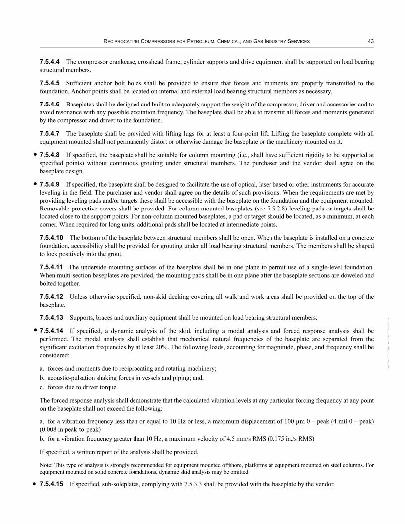
RECIPROCATING COMPRESSORS FOR PETROLEUM, CHEMICAL, AND GAS INDUSTRY SERVICES 43
•
•
•
•
--``,,,``,,`````,``,,,,,,,`,,`,,-`-`,,`,,`,`,,`---
7.5.4.4 The compressor crankcase, crosshead frame, cylinder supports and drive equipment shall be supported on load bearing structural members.
7.5.4.5 Sufficient anchor bolt holes shall be provided to ensure that forces and moments are properly transmitted to the foundation. Anchor points shall be located on internal and external load bearing structural members as necessary.
7.5.4.6 Baseplates shall be designed and built to adequately support the weight of the compressor, driver and accessories and to avoid resonance with any possible excitation frequency. The baseplate shall be able to transmit all forces and moments generated by the compressor and driver to the foundation.
7.5.4.7 The baseplate shall be provided with lifting lugs for at least a four-point lift. Lifting the baseplate complete with all equipment mounted shall not permanently distort or otherwise damage the baseplate or the machinery mounted on it.
7.5.4.8 If specified, the baseplate shall be suitable for column mounting (i.e., shall have sufficient rigidity to be supported at specified points) without continuous grouting under structural members. The purchaser and the vendor shall agree on the baseplate design.
7.5.4.9 If specified, the baseplate shall be designed to facilitate the use of optical, laser based or other instruments for accurate leveling in the field. The purchaser and vendor shall agree on the details of such provisions. When the requirements are met by providing leveling pads and/or targets these shall be accessible with the baseplate on the foundation and the equipment mounted. Removable protective covers shall be provided. For column mounted baseplates (see 7.5.2.8) leveling pads or targets shall be located close to the support points. For non-column mounted baseplates, a pad or target should be located, as a minimum, at each corner. When required for long units, additional pads shall be located at intermediate points.
7.5.4.10 The bottom of the baseplate between structural members shall be open. When the baseplate is installed on a concrete foundation, accessibility shall be provided for grouting under all load bearing structural members. The members shall be shaped to lock positively into the grout.
7.5.4.11 The underside mounting surfaces of the baseplate shall be in one plane to permit use of a single-level foundation. When multi-section baseplates are provided, the mounting pads shall be in one plane after the baseplate sections are doweled and bolted together.
7.5.4.12 Unless otherwise specified, non-skid decking covering all walk and work areas shall be provided on the top of the baseplate.
7.5.4.13 Supports, braces and auxiliary equipment shall be mounted on load bearing structural members.
7.5.4.14 If specified, a dynamic analysis of the skid, including a modal analysis and forced response analysis shall be performed. The modal analysis shall establish that mechanical natural frequencies of the baseplate are separated from the significant excitation frequencies by at least 20%. The following loads, accounting for magnitude, phase, and frequency shall be considered:
a. forces and moments due to reciprocating and rotating machinery; b. acoustic-pulsation shaking forces in vessels and piping; and, c. forces due to driver torque.
The forced response analysis shall demonstrate that the calculated vibration levels at any particular forcing frequency at any point on the baseplate shall not exceed the following:
a. for a vibration frequency less than or equal to 10 Hz or less, a maximum displacement of 100 µm 0 – peak (4 mil 0 – peak) (0.008 in peak-to-peak) b. for a vibration frequency greater than 10 Hz, a maximum velocity of 4.5 mm/s RMS (0.175 in./s RMS)
If specified, a written report of the analysis shall be provided.
Note: This type of analysis is strongly recommended for equipment mounted offshore, platforms or equipment mounted on steel columns. For equipment mounted on solid concrete foundations, dynamic skid analysis may be omitted.
7.5.4.15 If specified, sub-soleplates, complying with 7.5.3.3 shall be provided with the baseplate by the vendor.

44 API STANDARD 618
•
•
•
•
•
7.5.5 Soleplates and Rails
7.5.5.1 When soleplates or rails are specified, they shall be provided by the vendor, and they shall meet the requirements of 7.5.3.1.1 and 7.5.3.1.2 in addition to those of 7.5.1.
Note: See Annex L for a typical sketch.
7.5.5.2 Adequate working clearance shall be provided at the bolting locations to allow the use of standard socket or box wrenches and to allow the equipment to be moved using the horizontal and vertical jackscrews.
7.5.5.3 Soleplates shall be steel plates thick enough to transmit the expected loads from the equipment feet to the foundation and to facilitate grouting. In no case shall they be less than 40 mm (11/2 in.) thick.
7.5.5.4 If specified, sub-soleplates shall be provided with the soleplates by the vendor.
7.5.5.5 When sub-soleplates are specified, they shall be steel plates at least 25 mm (1 in.) thick. The finish of the sub-soleplates’ mating surfaces shall match that of the soleplates (see 7.5.1.5.2).
7.6 CONTROLS AND INSTRUMENTATION
7.6.1 General
7.6.1.1 Control systems, instrumentation, electrical systems, and their installation shall conform to the purchaser’s specifications and unless otherwise specified, shall comply with the requirements of ISO 10438-1 (or equivalents such as API 614, Chapter 1), except as modified by the following clauses.
7.6.1.2 The vendor shall provide all auxiliary system instrumentation as specified.
7.6.1.3 All instrumentation furnished by the compressor manufacturer requires the purchaser’s review. Freestanding panels are preferred. All instrumentation shall be securely supported to eliminate vibration and undue force on instrument piping and to prevent damage during shipment, storage, operation and maintenance.
7.6.1.4 Some controls may be shipped loose for field installation in the purchaser’s piping as agreed between the purchaser and the vendor. See 8.4.6 for shipment.
7.6.1.5 All tubing connections that must be dismantled for shipment shall have matched tags (initiation point, intermediate sections and application point) attached by stainless steel wire.
7.6.2 Control Systems
7.6.2.1 The compressor can be controlled on the basis of inlet pressure, discharge pressure, flow, or some combination of these parameters. This can be accomplished by suction throttling, valve unloaders, clearance pockets, speed variation, or a cooled bypass from discharge to suction. The control system can be mechanical, pneumatic, hydraulic, electric or electronic, or any combination thereof.
The following shall be as specified by the purchaser:
a. the type of control system (manual, automatic or programmable); b. the control signal;c. the control range; d. the process sensing lines handling flammable, toxic, corrosive or high-temperature fluids that require transduced signals to the instrumentation; e. the source of the control signal and its sensitivity and range;f. equipment to be furnished by the vendor;g. speed of response required.
7.6.2.2 The configuration of the control system shall be Arrangement 1, 2 or 3, in accordance with ISO 10438-2 or API 614, Chapter 2, as specified by the purchaser.
7.6.2.3 The vendor shall describe the complete control system (including alarms and shutdowns) in this scope of supply by means of logic diagrams in accordance with IEC 60848. When the control system is supplied by others, the vendor shall provide
--``,,,``,,`````,``,,,,,,,`,,`,,-`-`,,`,,`,`,,`---

RECIPROCATING COMPRESSORS FOR PETROLEUM, CHEMICAL, AND GAS INDUSTRY SERVICES 45
•
•
•
logic diagrams of the critical functions associated with the compressor operation (starting, stopping, capacity control, shutdowns etc.).
7.6.2.4 The unloading arrangement for start-up and shutdown shall be stated on the data sheets and shall be agreed by the purchaser and the vendor. If specified, automatic loading-delay interlock shall be provided to prevent automatic loaded starting. If specified, automatic immediate unloading shall be supplied to permit re-acceleration of the motor after a temporary electric power failure of an agreed maximum duration. The vendor and the purchaser shall agree on the modes and duration of unloaded and partially loaded compressor operation. The vendor shall be responsible for the loading/unloading sequence.
7.6.2.5 Capacity control for constant-speed units will normally be achieved by suction valve unloading, clearance pockets, or bypass (internal-plug type or external) or a combination of these methods. Step-less, reverse-flow capacity control acting on suction valves shall be subject to purchaser’s approval. Control operation shall be either automatic or manual as specified on the data sheet. Unless otherwise specified, five-step unloading shall provide nominal capacities of 100%, 75%, 50%, 25% and 0%; three-step unloading shall provide nominal capacities of 100%, 50% and 0%, and two-step unloading shall provide capacities of 100% and 0%.
7.6.2.6 Capacity control on variable-speed units is usually accomplished by speed control, but this can be supplemented by one or more of the control methods specified in 7.6.2.5.
Note: Reciprocating compressors are usually specified for constant-speed operation (see 6.1.10).
7.6.2.7 For variable speed control the speed of the compressor shall vary linearly with the control signal and an increase in signal shall increase speed. Unless otherwise specified, the full range of the purchaser’s signal shall correspond to the required operating range of the compressor for all specified operating conditions.
7.6.2.8 Unless otherwise specified, speed shall be adjustable by means of a hand speed changer.
7.6.2.9 Actuation of the control signal or failure of the signal or actuator shall neither prevent the governor from limiting the speed to the maximum permissible nor prevent manual regulation with the hand speed changer.
7.6.2.10 Clearance pockets shall normally be of the fixed type (pocket either open or closed). The use of variable volume clearance pockets requires purchaser’s approval. Each added clearance volume shall be included in the data sheets to indicate the clearance it adds to the cylinder.
7.6.2.11 When a machine-mounted capacity control system is specified, the vendor shall provide a panel complete with
a. a positive-detent-type master selector device (one for each service on multi-service compressors) to provide the specified load steps and,b. indicators to show at which step the machine is operating.
7.6.3 Instrument and Control Panels
Interconnecting shop-fabricated piping, tubing and wiring for controls and instrumentation, when furnished and installed by the vendor, shall be disassembled only as necessary for shipment.
7.6.4 Instrumentation
7.6.4.1 General Instruments shall be furnished and mounted locally, on a gauge board, or on a panel, as specified.
7.6.4.2 Tachometers If specified, a tachometer shall be provided for variable speed units. The purchaser shall specify the type, range, and indicator provisions of the tachometer. Unless otherwise specified, the tachometer shall be supplied by the driver vendor and shall be furnished with a minimum range of 0% – 125% of maximum continuous speed.
7.6.4.3 Temperature Measurement
7.6.4.3.1 Dial type temperature gauges shall be heavy duty and corrosion resistant. They shall be at least 125 mm (5 in.) diameter, bimetallic liquid filled types and, unless otherwise agreed, shall have black marking on a white background.
--``,,,``,,`````,``,,,,,,,`,,`,,-`-`,,`,,`,`,,`---
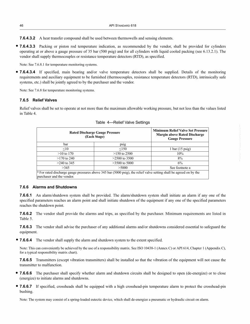
46 API STANDARD 618
•
•
•
•
•
--``,,,``,,`````,``,,,,,,,`,,`,,-`-`,,`,,`,`,,`---
7.6.4.3.2 A heat transfer compound shall be used between thermowells and sensing elements.
7.6.4.3.3 Packing or piston rod temperature indication, as recommended by the vendor, shall be provided for cylinders operating at or above a gauge pressure of 35 bar (500 psig) and for all cylinders with liquid cooled packing (see 6.13.2.1). The vendor shall supply thermocouples or resistance temperature detectors (RTD), as specified.
Note: See 7.6.8.1 for temperature monitoring systems.
7.6.4.3.4 If specified, main bearing and/or valve temperature detectors shall be supplied. Details of the monitoring requirements and auxiliary equipment to be furnished (thermocouples, resistance temperature detectors (RTD), intrinsically safe systems, etc.) shall be jointly agreed to by the purchaser and the vendor.
Note: See 7.6.8 for temperature monitoring systems.
7.6.5 Relief Valves
Relief valves shall be set to operate at not more than the maximum allowable working pressure, but not less than the values listed in Table 4.
Table 4—Relief Valve Settings
Rated Discharge Gauge Pressure (Each Stage)
Minimum Relief Valve Set Pressure Margin above Rated Discharge
Gauge Pressurebar psig<10 <150 1 bar (15 psig)
>10 to 170 >150 to 2500 10%>170 to 240 >2500 to 3500 8%>240 to 345 >3500 to 5000 6%
>345 >5000 See footnote aa For rated discharge gauge pressures above 345 bar (5000 psig), the relief valve setting shall be agreed on by the purchaser and the vendor.
7.6.6 Alarms and Shutdowns
7.6.6.1 An alarm/shutdown system shall be provided. The alarm/shutdown system shall initiate an alarm if any one of the specified parameters reaches an alarm point and shall initiate shutdown of the equipment if any one of the specified parameters reaches the shutdown point.
7.6.6.2 The vendor shall provide the alarms and trips, as specified by the purchaser. Minimum requirements are listed in Table 5.
7.6.6.3 The vendor shall advise the purchaser of any additional alarms and/or shutdowns considered essential to safeguard the equipment.
7.6.6.4 The vendor shall supply the alarm and shutdown system to the extent specified.
Note: This can conveniently be achieved by the use of a responsibility matrix. See ISO 10438-1 (Annex C) or API 614, Chapter 1 (Appendix C), for a typical responsibility matrix chart).
7.6.6.5 Transmitters (except vibration transmitters) shall be installed so that the vibration of the equipment will not cause the transmitter to malfunction.
7.6.6.6 The purchaser shall specify whether alarm and shutdown circuits shall be designed to open (de-energize) or to close (energize) to initiate alarms and shutdowns.
7.6.6.7 If specified, crossheads shall be equipped with a high crosshead-pin temperature alarm to protect the crosshead-pin bushing.
Note: The system may consist of a spring-loaded eutectic device, which shall de-energize a pneumatic or hydraulic circuit on alarm.

RECIPROCATING COMPRESSORS FOR PETROLEUM, CHEMICAL, AND GAS INDUSTRY SERVICES 47
•
•
•
•
Table 5—Minimum Alarm and Shutdown Requirements
Condition Alarm ShutdownHigh gas discharge temperature for each cylinder X XLow frame lube-oil pressure X XLow frame lube-oil level X —Cylinder lubricator system failure X —High oil-filter differential pressure X —High frame vibration X XHigh level in separator X XJacket coolant system failure X —Note: The “X” indicates when the condition occurs, alarm or shutdown is required; “—” indicates when the condition occurs, alarm or shutdown is not required.
7.6.7 Vibration and Position Detectors
7.6.7.1 The vendor shall furnish and mount a vibration detection and transducing device to provide the shutdown signal required by 7.6.6.2. Each device shall have a velocity or accelerometer-type detector, and each shall provide for each of the following functions:
a. continuous vibration measurement; b. alarm; c. shutdown.
The device and its mounting shall conform to API 670. Ball-and-seat or magnetic-type switches are unacceptable. If specified, additional devices shall be provided. The purchaser and the vendor shall agree on the type, number, and location of the devices to be mounted on the compressor frame (and on gear units, if applicable).
7.6.7.2 If specified, the vendor shall furnish and mount piston rod drop detectors of the non-contacting type to measure the vertical movement of each piston rod (piston rod drop). If specified, a non-contacting device shall also be installed to measure the horizontal movement of each piston rod. If a proximity-type probe is used for rod position indication, the probe and the associated oscillator-demodulator and connecting cable shall be installed and calibrated in accordance with API 670. Unless otherwise specified, each probe shall be mounted adjacent to the packing. Terminal boxes containing oscillator-demodulators shall not be mounted on the compressor. If the piston rod is coated, calibration of the device shall make allowances for the coating. See Annex C.
7.6.7.3 A one-event-per-revolution machined mark on the crankshaft shall be provided to permit synchronization on top dead center with a cylinder performance analyzer and/or rod drop detector. If specified, or when a non-contacting device is installed to indicate piston rod position, a corresponding phase-reference transducer(s) shall be provided. The transducer(s) shall be supplied, installed and calibrated in accordance with API 670.
7.6.7.4 If specified, the vendor shall furnish and mount piston rod drop detectors of the contact type, such as a mechanical roller or fuse metal plug (eutectic) type. The detail of the system shall be agreed between the vendor and the purchaser. Unless otherwise specified, each detector shall be mounted on the packing gland. An inert gas, instrument air, or hydraulics shall be used to pressurize the system. Diaphragm type pressure switches shall be used to sense loss of pressure.
7.6.8 • Temperature Monitoring Systems
If specified, the vendor shall supply a temperature monitoring system installed and calibrated in accordance with API 670. The temperatures monitored shall be as specified by the purchaser and may include but are not limited to:
a. main bearing temperatures;b. valve temperatures;c. packing temperatures;d. crosshead pin bearing temperatures.
--``,,,``,,`````,``,,,,,,,`,,`,,-`-`,,`,,`,`,,`---

48 API STANDARD 618
•
•
•
7.7 PIPING AND APPURTENANCES
7.7.1 General
7.7.1.1 Piping and installation shall first conform to the purchaser’s specifications. Unless otherwise specified, in the absence of purchaser specifications, piping shall comply with the requirements of ISO 10438-1 or API 614, Chapter 1, and ISO 10438-3 or API 614, Chapter 3, except as modified by the following clauses.
7.7.1.2 The extent of process and auxiliary piping to be supplied by the vendor shall be as specified by the purchaser.
7.7.1.3 If special flanges, not in accordance with the specified standards, are unavoidable at the purchaser connection, the vendor shall supply a welding neck companion flange, bolting, and gasketing to be installed by others. The purchaser shall be advised of this situation in the proposal.
Note: Cylinder connections are discussed in 6.8.4.
7.7.1.4 If specified, piping, pulsation suppression devices and knockout vessels at the initial and interstage suction points shall have provisions for heat tracing and insulation.
Note 1: During certain atmospheric conditions, air can be at or close to saturated conditions; also, multi-stage air or hydrocarbon gas compressors will usually have saturated conditions following intercooling.
Note 2: The user should ensure that the quantity of liquid carried into the inlet system is minimized and that any such carry-over does not collect in the inlet system and form slugs.
Note 3: The design of a compressor inlet system for operation with a gas at or near saturation should consider the following factors:
—liquid separator close to the compressor suction;—separator efficiency over the operating flow range;—sufficient separator volume to handle incoming slugs;—sufficient gas velocity in the line from the separator to the cylinder to minimize liquid dropout;—elimination of low points between the separator and cylinder;—slope of lines;—insulation to minimize heat loss; and —heat tracing to maintain the gas at or above the dew point.
7.7.1.5 The following items shall terminate with flanged connections at the edge of the base:
a. connections for interconnecting piping between equipment groupings, and off-base facilities, b. connections for air, water, steam, and other utility services to a base area, c. other purchaser connections.
Vendor-supplied piping systems shall terminate in flanged connections. Instrument tubing connections shall terminate in a flange or a threaded connection in accordance with standard. Piping and component drains and vents shall terminate with a plugged or blind-flanged valve, accessible from the edge of the base or from a work area. This is to keep work areas and walkways as free as possible from obstructions. All piping supplied by the vendor shall be prefabricated. Any piping that cannot be shipped in the assembled state shall be preserved, match marked and tagged to facilitate field assembly.
7.7.1.6 If specified, the vendor shall review drawings of all piping, appurtenances (pulsation suppression devices, intercoolers, aftercoolers, separators, knockouts, air intake filters and expansion joints) and vessels immediately upstream and downstream of the equipment and supports. The purchaser and the vendor shall agree on the scope and consequences of this review.
7.7.1.7 Internals of piping and appurtenances shall be accessible through openings or by dismantling for complete visual inspection and cleaning.
7.7.1.8 Connections DN 40 (11/2 NPS) and smaller shall be designed to minimize overhung weight. Connections shall be forged fittings or shall be braced back to the main pipe in at least two planes to avoid breakage due to pulsation-induced vibration. Bracing shall be arranged to occupy minimum space.
Note 1: Slip-on flanges are not used on piping and appurtenances around reciprocating compressors due to their insufficient fatigue life.
Note 2: The attention of the user of this standard is drawn to the possibility of hazardous situations arising from the incompatibility of ISO and ANSI pipe thread standards.
--``,,,``,,`````,``,,,,,,,`,,`,,-`-`,,`,,`,`,,`---

RECIPROCATING COMPRESSORS FOR PETROLEUM, CHEMICAL, AND GAS INDUSTRY SERVICES 49
•
•
--``,,,``,,`````,``,,,,,,,`,,`,,-`-`,,`,,`,`,,`---
7.7.1.9 All pipe flanges mating with cast iron compressor flanges shall be flat faced and utilize full-faced gaskets.
Note: For the purposes of this clause the term compressor flanges does not include faced and studded bosses.
7.7.1.10 Threaded piping joints shall not be used for flammable or toxic fluids, unless otherwise agreed, in accordance with 6.8.4.1.5. Where threaded joints are permitted, they shall not be seal welded.
Note: Threaded joints are typically only allowed for connections to non-weldable materials such as cast iron, instruments, or locations that must be disassembled for maintenance.
7.7.1.11 Control valves shall have flanged ends.
7.7.1.12 Except where ring type joints are required or specified, pipe flange gaskets shall be flat, asbestos-free material up to and including ANSI Class 300 pressure ratings, and spiral wound gaskets for higher ratings. Spiral wound gaskets shall have external centering rings and windings of austenitic stainless steel or other suitable corrosion resistant materials (Monel, Inconel etc.) depending on the fluids handled.
Note: Flared tubing fittings are not recommended for reciprocating compressor applications.
7.7.1.13 Special requirements for piping, flanges, valves, and other appurtenances in services such as hydrogen, hydrogen sulfide, or other toxic services, shall be specified by the purchaser.
7.7.1.14 Inert gas purge systems shall be stainless steel downstream of the filters.
7.7.1.15 All flanges shall be socket-weld or weld-neck flanges. Lap-joint or slip-on flanges shall not be used.
7.7.2 Frame Lubrication Oil Piping
7.7.2.1 For lubricating oil piping systems (with its mounted appurtenances) located within the confines of the main unit base area, the vendor shall supply a complete system, including any assembly (console) base and any packaged unit accessory. The vendor shall provide interconnecting piping when auxiliary equipment is specified to be located immediately adjacent to the compressor in the vendor’s recommended location (see 6.14.2 and 7.7.1.5).
7.7.2.2 The vendor shall specify the maximum piping distance between the main frame and any auxiliary oil console, and the required elevation difference.
7.7.2.3 Unless otherwise specified, oil piping (with the exception of cast-in-frame lines or passages) and tubing, including fittings, shall be stainless steel.
7.7.2.4 After fabrication, oil lines shall be thoroughly cleaned.
7.7.2.5 Heads of oil-actuated control valves shall be vented back to the reservoir. If specified, instrument sensing lines to shutdown switches shall have a continuous through-flow of oil.
7.7.3 Forced-feed Lubricator Tubing
7.7.3.1 Oil feed lines from force-feed lubricators to cylinder and packing lubrication points shall be at least 6 mm (1/4 in.) outside diameter with a minimum wall thickness of 1.5 mm (0.065 in.). Tubing shall be seamless austenitic stainless steel. Fittings shall be austenitic stainless steel. See 6.14.3.1.7 for check valves.
Note: For high-pressure compressors, heavier wall thickness tubing can be required.
7.7.3.2 Tubing shall be run together where possible. When winterization is specified, the tubing shall stand off from the machine to allow insulation.
7.7.4 Coolant Piping
7.7.4.1 Unless otherwise specified, the vendor shall supply piping with a single inlet and a single outlet connection on each cylinder requiring cooling (see Figure G-1, Plan C).
7.7.4.2 Both the coolant inlet line and the coolant outlet line to each compressor cylinder shall be provided with an isolation valve. A globe valve with union shall be provided on the main outlet line from each cylinder. A sight flow indicator shall be installed in the common coolant outlet line from each cylinder. Where more than one coolant inlet and outlet point exists on a

50 API STANDARD 618
•
•
•
•
•
cylinder, one sight flow indicator and a regulating globe valve shall be provided for each coolant outlet point on each cylinder. Cylinder coolant piping shall be equipped with valved coolant vents and drains (see Figure G-1).
7.7.4.3 When the purchaser specifies the vendor to supply coolant piping on the compressor, the vendor shall supply a piping system for all equipment mounted on the compressor or compressor base. The piping shall be arranged to provide a single inlet connection and a single outlet connection for each water circuit operating at different inlet temperature levels and shall include a coolant control valve and a flow indicator as noted in 7.7.4.2. Series-type circuits shall have the necessary valved bypasses to provide temperature control.
7.7.4.4 Where a thermosyphon or a static cooling system is provided (see 6.8.3), the vendor shall furnish piping with a drain valve at its lowest point and an expansion tank (complete with fill-and-vent connections and level indication) sized to prevent overflow of coolant (see Figure G-2, Plans A and B). A thermometer is required for a thermosyphon system.
7.7.5 Instrument Piping
Initial connections for remote mounted pressure instruments shall comprise an isolation valve conforming to the same requirements as the system to which it is connected. Beyond the initial isolation valve, piping or tubing not less than 10 mm (3/8in.) outside diameter may be used. Where convenient, a common primary connection may be used for remotely mounted instruments that measure the same pressure. Such common connections shall not be smaller than DN 15 (NPS 1/2) and separate secondary isolation valves shall be provided for each instrument. Where a pressure gauge is to be used for testing pressure alarm or shutdown switches, common connections are required for the pressure gauge and associated switches.
7.7.6 Process Piping
7.7.6.1 The vendor may be required to supply process piping to the extent and requirements specified by the purchaser. See ISO 10438-1 or API 614, Chapter 1.
7.7.6.2 When compressor process inlet piping and pulsation suppression equipment are furnished by the vendor, provisions shall be made for the insertion of temporary start-up screens just upstream of the suction pulsation suppression device. The design of the piping system, the suction pulsation suppression device and the temporary start-up screens shall afford easy removal and reinsertion of the screens without the necessity of pipe springing.
7.7.6.3 • When the screens are supplied by the vendor, the design, location, and orientation of the screens shall be agreed by both the purchaser and the vendor prior to manufacture or purchase.
7.7.6.4 If specified, the vendor shall supply the removable spool pieces that accommodate temporary start-up screens. Sufficient pressure taps to allow monitoring of the pressure drop across the screen shall be provided.
7.7.7 Distance Piece Vent and Drain Piping
7.7.7.1 The vendor shall supply distance piece vent and drain piping to the extent and requirements specified.
7.7.7.2 Drain and vent piping serving individual cylinders shall not be less than DN 25 (NPS 1) or 20 mm (3/4 in.) outside diameter if tubing is used. Drain and vent headers shall not be less than DN 50 (NPS 2). Vent connections in the packing case and interconnecting tubing within a distance piece shall be of austenitic stainless steel and of at least 6 mm (1/4 in.) outside diameter with a minimum wall thickness of 1.24 mm (0.049 in.). See Annex I for a typical distance piece vent and drain system.
7.8 INTERCOOLERS, AFTERCOOLERS, AND SEPARATORS
7.8.1 Intercoolers and Aftercoolers
7.8.1.1 If specified, the vendor shall furnish an intercooler between each compression stage.
Unless otherwise specified, intercoolers shall comply with ISO 10438-1 or API 614, Chapter 1.
7.8.1.2 If specified, aftercoolers shall be furnished by the vendor.
Unless otherwise specified, aftercoolers shall comply with ISO 10438-1 or API 614, Chapter 1.
Note: Intercooling and after cooling of gasses from reciprocating compressors present some unique phenomena to be considered in the design of exchangers.
--``,,,``,,`````,``,,,,,,,`,,`,,-`-`,,`,,`,`,,`---

RECIPROCATING COMPRESSORS FOR PETROLEUM, CHEMICAL, AND GAS INDUSTRY SERVICES 51
•
•
•
Caution should be exercised regarding:
—whether the gas should be on the tube side or on the shell side; very small pressure pulsation levels multiplied by the larger areas of the pass separation plates can possibly produce very high vibratory forces in the tube bundle;—the use of shell side rupture discs, relief valves or similar devices;—the use of air-cooled heat exchangers because of their susceptibility to pulsation-induced vibration in systems and structures;—the susceptibility of heat exchangers and their supporting structures to pulsation-induced vibration. Mechanical natural frequencies should not be coincident with pulsation frequencies in the heat exchanger systems.
7.8.1.3 Unless otherwise specified, the water side of heat exchangers shall be designed in accordance with 6.1.7.
7.8.1.4 The choice of water on the tube or shell side of shell and tube heat exchangers shall be agreed between the vendor and purchaser, with due consideration to pulsations, pressure levels, corrosion and maintainability.
Note: The purchaser may specify that the vendor shall furnish the fabricated piping between the compressor stages and the intercoolers and aftercoolers. See ISO 10438-1 or API 614, Chapter 1.
7.8.2 Separators
7.8.2.1 If specified, liquid separation and collection facilities in accordance with 7.8.2.2 through 7.8.2.8 shall be provided upstream of the compressor, and after every intercooler.
Note: Intercooling may result in condensation. See 6.8.1.2 and 7.7.1.4 and associated notes.
7.8.2.2 The type of liquid separation device and whether it is to be arranged in a separate vessel, or integral with the pulsation suppression device, or integral with the intercooler, shall be mutually agreed upon by the vendor and purchaser. In the case of cylinders handling gases that are or can become saturated, appropriate means should be used, in addition to the integral moisture removal section, to prevent liquid carry over into the compressor cylinder. Special attention should be paid to integral separators in pulsation dampener devices to avoid mechanical vibration in the separator pack.
Note 1: Moisture removal sections of pulsation suppression devices have demonstrated a low separation efficiency when oscillating flow effects were not considered.
Note 2: Drain sumps on pulsation suppression devices can lead to longer cylinder connection nozzles, and can result in high vibrations on the drain sump instrumentation.
7.8.2.3 The liquid separation device shall remove 99% of all droplets of 10 microns or larger. Pressure drop shall be as defined in 7.9.2.6.3.1.
7.8.2.4 Integral moisture removal sections shall have a drain sump or boot extending below the device shell into which the separated liquid is directed.
7.8.2.5 Unless otherwise agreed, the capacity of the sump or boot of an integral separator, or lower part of the separate separation vessel, shall be sufficient to contain the maximum expected liquid flow from any specified operating condition for not less than 15 minutes, without activating any alarm.
7.8.2.6 The liquid separation device shall be equipped with a drain connection of not less than DN 25 (1 NPS), gauge glass connections, and a level shutdown switch connection. The connections shall be flanged and fitted with blinds.
7.8.2.7 If specified, an automatic drainage system shall be provided. For air or inert gas service, this automatic drainage system may comprise a float-operated trap with a manual bypass. In all other cases, the drainage system shall comprise a separate level control valve with a manual bypass, operated by a level controller of an agreed type.
7.8.2.8 If specified, the drain sump or boot or lower part of the separate separation vessel shall be provided with a level indicator and alarm and shutdown devices. Where a high level alarm and a high level shutdown are specified, the capacity of the vessel or boot between the levels shall be equivalent to the maximum expected liquid flow for not less than 5 minutes.
--``,,,``,,`````,``,,,,,,,`,,`,,-`-`,,`,,`,`,,`---

52 API STANDARD 618
•
•
7.9 PULSATION AND VIBRATION CONTROL
7.9.1 General
7.9.1.1 The objective of the requirements of this subclause is to avoid problems with
a. vibration,b. performance,c. reliability, andd. flow measuring error caused by acoustical interaction between the compressor and the system in which it operates.
7.9.1.2 The basic techniques used for control of detrimental pulsations and vibrations are the following:
a. system design based on analysis of the interactive effects of pulsations and the attenuation requirements for satisfactory levels of piping vibration, compressor performance, valve life, and operation of equipment sensitive to flow pulsation;b. utilization of pulsation suppression devices such as: pulsation filters and attenuators; volume bottles, with or without internals; choke tubes; orifice systems; and selected piping configurations;c. mechanical restraint design; specifically including such things as: type, location, and number of pipe and equipment clamps and supports.
Note: Completion of purchaser requirements for pulsation suppressors (data sheet page 4, lines 15 through 26, and pages 13 and 14) is essential for the vendor to quote and fabricate these accessories.
7.9.2 • Alternate Operating Conditions
Operation with alternative gases, alternative conditions of service, or alternative start-up conditions shall be as specified. Pulsation suppression devices shall be mechanically suitable for all specified conditions and gases.
When a compressor is to be operated on two or more gases of dissimilar molecular weights (for example, hydrogen and nitrogen), pulsation levels shall be optimized for the gas on which the unit must operate for the greater length of time.
Pulsation levels shall be reviewed for all specified alternative gases, operating conditions, and loading steps to assure that pulsation levels will be acceptable under all operating conditions. By mutual agreement, the pulsation level criteria of 7.9.4.2.5.2 may be exceeded for alternative conditions, however, the other design criteria of 7.9.4.2.5.2 shall be met.
Note: For the purposes of screening the need for reviewing alternate gases, a significant gas change is one that results in either a 30% change in the speed of sound, or a molar mass change in the ratio of 1.7:1.
7.9.3 Multiple Unit Additive Effects
7.9.3.1 The purchaser shall specify when the compressor is to be operated in conjunction with other compressor units and their associated piping systems. In this case, the additive effect of pressure pulsations from multiple units shall be addressed. The scope of the analysis shall be based on agreement between the purchaser and vendor. If the additive effect indicates a requirement for modifications to an existing system to obtain acceptable pulsation levels, such modifications shall be based on agreement between the purchaser and the vendor.
Note: In some cases it may be necessary to impose tighter limits for each new compressor than those defined in 7.9.4.2.5 in order for the combined system to achieve acceptable pulsation levels.
7.9.3.2 For preliminary sizing, and, if specified, for Design Approach 1 (see 7.9.4.2.2), pulsation suppression devices shall have minimum suction surge volume and minimum discharge surge volume (not taking into account liquid collection chambers), as determined from Equations 3, 4 and 5, but in no case shall either volume be less than 0.03 m3 (1 ft3).
In SI units
Vs 8.1 PDkTs
M-------⎝ ⎠
⎛ ⎞14---
×= (3)
Vd 1.6Vs
r1k---
-----⎝ ⎠⎜ ⎟⎜ ⎟⎛ ⎞
= (4)
--``,,,``,,`````,``,,,,,,,`,,`,,-`-`,,
`,,`,`,,`---
RECIPROCATING COMPRESSORS FOR PETROLEUM, CHEMICAL, AND GAS INDUSTRY SERVICES 53
•
Vs and Vd > 0.03 (5)
In USC units
Vs 7 PDkTs
M-------⎝ ⎠
⎛ ⎞14---
×=
Vd 1.6Vs
r1k---
-----⎝ ⎠⎜ ⎟⎜ ⎟⎛ ⎞
×=
Vs and Vd > 1.0
where
VS is the minimum required suction surge volume in m3 (ft3);
Vd is the minimum required discharge surge volume in m3 (ft3);
k is the isentropic compression exponent at average operating gas pressure and temperature;
r is the stage pressure ratio at cylinder flanges (absolute discharge pressure divided by absolute suction pressure);
TS is the absolute suction temperature in K (°R);
M is the molar mass;
PD is the total net displaced volume per revolution of all compressor cylinders to be manifolded in the surge volume in m3/r (ft3/r).
The internal diameter of the surge volume shall be based on the minimum surge volume overall length required to manifold the compressor cylinders. For a single-cylinder surge volume, the ratio of surge volume length to internal diameter shall not exceed 4.0. The inside diameter of spherical volumes shall be calculated directly from the volumes determined by Equations 3, 4 and 5.
Equations 3, 4 and 5 are intended to ensure that reasonably sized pulsation suppression devices are included with the compressor vendor’s proposal and should provide satisfactory sizes for most applications. In some instances, the sizes should be altered according to the simulation analysis employed by Design Approaches 2 and 3. Sizing requirements can be substantially influenced by operating parameters, interaction among elements of the overall system, and mechanical characteristics of the compressor system. The magnitude of the effects of these factors cannot be accurately predicted at the outset.
Some compressor applications require the use of properly designed low-pass acoustic filters. A low-pass acoustic filter consists of two volumes connected by a choke tube. The volumes can be made up of two separate suppressors or one suppressor with an internal baffle. A procedure for preliminary sizing of low-pass acoustic filters is presented in Annex O. The design shall be confirmed by an acoustic simulation.
7.9.4 Design and Documentation
7.9.4.1 Design Approach Selection
7.9.4.1.1 Unless otherwise specified, Table 6 shall be utilized to determine the Design Approach. For applications above an absolute pressure of 350 bar (5000 psia), the purchaser and the vendor shall agree on the criteria for pulsation suppression.
Note: A detailed description of the three design approaches is given in 7.9.4.2.
7.9.4.1.2 The purchaser shall specify if the analysis is to be performed by the vendor or a third party. If a third party is selected to perform the analysis, the compressor vendor shall provide the necessary information required for the third party vendor to complete the analysis.
--``,,,``,,`````,``,,,,,,,`,,`,,-`-`,,`,,`,`,,`---

54 API STANDARD 618
--``,,,``,,`````,``,,,,,,,`,,`,,-`-`,,`,,`,`,,`---
7.9.4.2 Design Approaches
7.9.4.2.1 General
The design approach choices are:
a. Design Approach 1—Empirical Pulsation Suppression Device Sizing.b. Design Approach 2—Acoustic Simulation and Piping Restraint Analysis.c. Design Approach 3—Acoustic Simulation and Piping Restraint Analysis plus Mechanical Analysis (with Forced Mechanical Response Analysis if necessary).
Unless otherwise specified, each design approach includes all of the elements of preceding approaches, unless superseded by more comprehensive methods. Elements of the various design approaches are summarized in 7.9.4.2.2, 7.9.4.4, and 7.9.4.5. Flowcharts detailing work processes for each Design Approach can be found in Annex M.
Table 6—Design Approach Selection
Absolute Discharge PressureRated Power per Cylinder
Kw/cyl < 55(hp/cyl < 75)
55 < Kw/cyl < 220(75 < hp/cyl < 300)
220 < Kw/cyl(300 < hp/cyl)
P < 35 bar(P < 500 psi) 1 2 2
35 bar < P < 70 bar(500 psi < P < 1000 psi) 2 2 3
70 bar < P < 200 bar(1000 psi < P < 3000 psi) 2 3 3
200 bar < P < 350 bar(3000 psi < P < 5000 psi) 3 3 3
Note: API 688 provides a discussion of the different operating and mechanical parameters that should be taken into account when considering a design approach different from that indicated by Table 6, especially if less analysis is contemplated.
7.9.4.2.2 Design Approach 1—Empirical Pulsation Suppression Device Sizing
Pulsation suppression devices shall be designed using proprietary and/or empirical analytical techniques to meet line side pulsation levels required in 7.9.4.2.5.2.2.1, and the maximum pressure drop allowed in 7.9.4.2.5.3.1, based on the normal operating condition. Acoustic simulation analysis is not performed when using this design approach.
7.9.4.2.3 Design Approach 2—Acoustic Simulation and Piping Restraint Analysis
7.9.4.2.3.1 General
Design Approach 2 is pulsation control through the use of pulsation suppression devices and proven acoustic techniques in conjunction with mechanical analysis of pipe runs and anchoring systems (clamp design and spacing) to achieve control of vibrational response. This approach includes the evaluation of acoustic interaction between the compressor, pulsation suppression devices and associated piping, including pulsation effects on compressor performance and an evaluation of acoustic shaking forces in the pulsation suppression devices. The evaluation is accomplished by modeling the compressor system and the piping and then performing an acoustic simulation to determine the response.
7.9.4.2.3.2 Compressor System Model
Pulsation suppression devices (or dampers) are initially sized using Design Approach 1, and analyzed using acoustic simulation. The compressor system model normally includes piston and valve kinematics, cylinder passages, pulsation suppression device(s) and terminates at the line-side nozzle flange. This model is only used for the acoustic simulation. There is no mechanical modeling of the compressor system to evaluate mechanical resonances in Design Approach 2.

RECIPROCATING COMPRESSORS FOR PETROLEUM, CHEMICAL, AND GAS INDUSTRY SERVICES 55
--``,,,``,,`````,``,,,,,,,`,,`,,-`-`,,`,,`,`,,`---
7.9.4.2.3.3 Piping System Model
For applications where the piping system is not defined, the acoustic simulation can be performed with the piping system initially modeled with an infinite length, acoustically non-reflective line. The allowable design limits of 7.9.4.2.3.4 apply. This step is called a pre-study and is also referred to as a “bottle check” or “damper check.” For applications where the piping system is defined, the pre-study may be omitted. The piping model replaces the acoustically non-reflective line in the simulation model.
7.9.4.2.3.4 Pre-study
When the acoustic simulation is performed prior to completion of the piping system model, the maximum allowable pressure pulsation level at the pulsation suppression device line-side nozzle flange shall be 80% of the allowable value defined by Equation 8 for single pulsation suppression devices, and 70% of the allowable value defined by Equation 8 when two or more pulsation suppression devices are attached to common piping.
Note: A single pulsation device means a device that is not connected to another by common piping. Examples include: a single cylinder first stage suction device of a single unit; a single cylinder discharge pulsation device of a single unit; and, single unit first stage suction or final stage discharge device that manifolds all the cylinders that generate pulsation in the particular piping system. Examples of two or more pulsation suppression devices attached by common piping are: interstage devices (even with intercoolers); single units with multiple pulsation suppression devices for first stage suction or for final stage discharge piping systems; and multiple units attached to common piping systems.
In order to meet contract delivery, all parties should cooperate to schedule the design of the pulsation suppression device, the pulsation analysis, and piping design. Ordering components after the pre-study can facilitate the procurement of long delivery components of the pulsation suppression devices such as end caps, nozzles and cylindrical sections. However, the final length, nozzle orientation and need for vessel internals cannot be optimized until the piping system is added to the acoustic model. Therefore, it should be noted, that if the pulsation suppression devices are fabricated prior to finalizing the piping configuration the only remaining system design optimization methods available to the designer is the installation of orifices, piping modifications, and stiffening of the piping system. This sometimes leads to the need to order different pulsation suppression devices to provide an adequate system, with a consequent negative impact on schedule.
7.9.4.2.3.5 Acoustic Simulation
When the layout and sizing of the piping system is completed, an acoustic simulation of the complete system shall be performed to confirm compliance with the requirements of 7.9.4.2.5 or to identify changes necessary to achieve compliance.
7.9.4.2.3.6 Mechanical Review and Piping Restraint Analysis
A mechanical review shall be performed using span and basic vessel mechanical natural frequency calculations to avoid mechanical resonance. This review shall result in a table of various pipe sizes that indicates the maximum allowable span (based on the maximum compressor operating speed) between piping supports as a function of pipe diameter, and the separation margin requirements of 7.9.4.2.5.2.3.3.
Note 1: In the piping design, when clamps are used to avoid mechanical resonances, the thermal flexibility effects should also be considered.
Note 2: To accurately predict and avoid piping resonances, the supports and clamps must dynamically restrain the piping. Piping restraints are only considered to be dynamically restraining when they have either enough mass or stiffness to enforce a vibration node at the restraint. This requirement is difficult to achieve with overhead piping and/or the use of simple supports, hangers, and guides.
7.9.4.2.4 Design Approach 3—Acoustic Simulation and Piping Restraint Analysis Plus Mechanical Analysis— (with Forced Mechanical Response Analysis if Necessary)
7.9.4.2.4.1 General
This approach is identical to Design Approach 2, with the addition of a mechanical analysis of the compressor cylinder, compressor pulsation suppression devices and associated piping systems including interaction between acoustic and mechanical system responses. Forced mechanical response is included when necessary. Both acoustic and mechanical methods are used to arrive at the most efficient and cost effective plant design.

56 API STANDARD 618
7.9.4.2.4.2 Step 3a—Mechanical Natural Frequency Analysis of the Compressor and Piping System to Avoid Coincidence with Significant Shaking Forces
a. The starting point of the mechanical model is either the crankcase-to-foundation interface or the crosshead guide-to-crankcase interface. For modeling accuracy, this location shall be relatively rigid when compared to the rest of the compressor mechanical model and/or it shall be accurately described by a six degree of freedom spring. The compressor mechanical model end point is the second pipe clamp on the suction and discharge piping moving away from the line side nozzles of the pulsation suppression devices. The factors that can influence the accuracy of the model are discussed in more detail in API 688. If specified, this modeling will also include an analysis of the stresses found in the pulsation suppression device internals in accordance with 7.9.5.1.22 and 7.9.5.1.23.
Note 1: The intent is to avoid mechanical resonance of the compressor cylinders, pulsation suppression devices, and piping system at frequencies where high shaking forces also exist.
Note 2: In some cases the compressor frame, crosshead guides and cylinders, mounted on a concrete foundation, can be considered to be relatively rigid, and can be modeled using rigid elements.
Note 3: The compressor and pulsation suppression device mechanical model was formerly known as the compressor manifold model.
b. An analysis of the compressor and piping system shall be done to predict the mechanical natural frequencies. The mechanical and acoustic system shall be designed to meet the separation margin criteria of 7.9.4.2.5.3.2 and the shaking forces shall not exceed the limits found in 7.9.4.2.5.2.3.
Note: Geometrically-complex areas of the system such as cylinders, distance pieces, crosshead guides, frames, pulsation suppression device nozzles, and piping, where span calculations cannot be applied accurately, are analyzed to determine mechanical natural frequencies, usually with vendor proprietary methods, shop measured data, or finite element methods; with the intent of avoiding mechanical resonances at frequencies where significant shaking forces also exist
7.9.4.2.4.3 Step 3b1—Forced Mechanical Response Analysis of the Compressor Mechanical Model
When the excitation frequency separation margins or the shaking force amplitude guidelines for pulsation suppression devices cannot be met, a forced-mechanical-response analysis of the compressor mechanical model to the pulsation-induced forces and cylinder-gas forces shall be performed. The allowable cyclic stress criteria in 7.9.4.2.5.2.5 shall apply. The compressor vendor shall supply the allowable vibration limits for compressor components such as cylinders, distance pieces and crankcases.
Note: The allowable compressor vibration levels are generally the limiting design criteria. This analysis predicts the cyclic stress in the pulsation suppression devices and associated piping. It is not intended that analysis of the cyclic stresses in the compressor components be included in this design approach. The compressor components are included in the model only for the purpose of enabling the analysis of the effects of their flexibility and dynamic movement on the pulsation suppression devices. The compressor manufacturer is expected to provide vibration criteria to ensure that no fatigue failures or premature wear of compressor components occur, in accordance with 6.1.1.
7.9.4.2.4.4 Step 3b2—Forced Mechanical Response of the Piping System
When the excitation frequency separation margins or the shaking force amplitude guidelines for the piping system cannot be met, a forced-mechanical response analysis of the piping system to acoustic shaking forces shall be performed. The allowable vibration and cyclic stress limits in 7.9.4.2.5.2.4 and 7.9.4.2.5.2.5 respectively shall apply. The model end points shall be defined by the analyst in agreement with the purchaser; in general, the piping system model should include all of the piping that was included in the acoustic model. Factors that can influence the accuracy of the model are discussed in more detail in API 688.
When forced mechanical response analysis of the piping system is performed without doing a forced mechanical response analysis of the compressor mechanical model, the starting point of the piping system is at the compressor cylinder flanges, which are assumed to be rigid.
Note: As with Step 3b1, the vibration is generally the limiting design consideration, because when the vibration levels are within the recommended allowable limits, the allowable stress levels are usually not approached. The exception is where high stress concentrations occur at large diameter reductions such as nozzle connections and weldolets for small piping on significantly larger piping.
7.9.4.2.5 Design Criteria
7.9.4.2.5.1 General
Pulsation suppression devices and techniques applied in accordance with Design Approaches 1, 2, and 3 shall satisfy the basic criteria in 7.9.4.2.5.2, and the other criteria in 7.9.4.2.5.3.
--``,,,``,,`````,``,,,,,,,`,,`,,-`-`,,`,,`,`,,`---

RECIPROCATING COMPRESSORS FOR PETROLEUM, CHEMICAL, AND GAS INDUSTRY SERVICES 57
7.9.4.2.5.2 Basic Criteria
To evaluate compliance with the basic criteria, the following procedure applies:
1. Preliminary pulsation suppression device sizing. Determine pressure drop across the pulsation suppression device. The criteria as described in 7.9.4.2.5.2.2.1 and 7.9.4.2.5.3.1 shall be met. Design Approach 1 is complete.
For Design Approaches 2 and 3:
2. Pre-study of pulsation suppression devices (if required). Determine pulsations at the compressor cylinder flanges, and at the line side nozzle of the pulsation suppression device. The criteria as described in 7.9.4.2.5.3.1, 7.9.4.2.5.2.1, and 7.9.4.2.5.2.2.2 de-rated as in accordance with 7.9.4.2.3.4 shall be met. The criteria for pulsation suppression device non-resonant shaking force are described in 7.9.4.2.5.2.3.3.3. After the layout of the piping system is completed, pulsation analysis of the complete pipe system is undertaken. The criteria for maximum pressure drop and pulsations are given in 7.9.4.2.5.3.1, 7.9.4.2.5.2.1, and 7.9.4.2.5.2.2.2. The criteria for pulsation suppression device non-resonant shaking forces are given in 7.9.4.2.5.3.3.
If these criteria are met and Design Approach 2 is specified then Step 4 shall be performed. If Design Approach 3 is specified then proceed directly to Step 5.
4. Specify maximum piping spans and determine vessel mechanical natural frequencies utilizing piping tables and basic vessel calculations. The minimum allowable mechanical natural frequencies are given in 7.9.4.2.5.3.2.
If the criteria for Step 3 and Step 4 are met, Design Approach 2 analysis is complete. If the criteria under Steps 3 or 4 are not met then either a redesign or, Steps 5 and 6 shall be performed:
5. Develop a mechanical model and determine mechanical natural frequencies; the minimum separation margins are in 7.9.4.2.5.3.2.6. Determine the maximum allowable shaking forces in accordance with 7.9.4.2.5.2.3 and check whether these are higher than the acoustic shaking forces calculated by acoustic simulation.
If the criteria for Step 5 and Step 6 are met, Design Approach 3 analysis is complete.
For the compressor system, if the criteria in Step 5 or Step 6 are not met, either a redesign or, Step 8 shall be performed.
For the piping system, if the criteria in Step 5 or Step 6 are not met, either a redesign or Step 7 shall be performed.
7. Determine pipe vibrations based on the maximum calculated acoustic shaking forces. Criteria for maximum allowable pipe vibrations are in 7.9.4.2.5.2.4.
If the vibration criteria in Step 7 are not met, either a redesign or Step 8 shall be performed:
8. Calculate dynamic stresses in the compressor system or piping system, as required. Maximum allowable cyclic stresses are in 7.9.4.2.5.2.5. For the compressor system, also compare the vibration levels calculated to those supplied by the compressor vendor.
If the criteria for Step 7 or Step 8 are met, Design Approach 3 analysis is complete. If the criteria are not met, redesign is required.
Note: The calculations to determine the criteria for allowable shaking forces in Step 6 of this subclause may be omitted if the piping vibration analysis is performed according to Step 7 directly after Step 5.
7.9.4.2.5.2.1 Maximum Allowable Compressor Cylinder Flange Pressure Pulsation
Unless other criteria (such as loss of compressor efficiency) are specified, the unfiltered peak-to-peak pulsation level at the compressor cylinder flange, as a percentage of average absolute line pressure, shall be limited to the lesser of 7% or the value computed from Equation 6.
Pcf 3R%= (6)
--``,,,``,,`````,``,,,,,,,`,,`,,-`-`,,`,,`,`,,`---

58 API STANDARD 618
where
Pcf is the maximum allowable unfiltered peak-to-peak pulsation level, as a percentage of average absolute line pressure at the compressor cylinder flange;
R is the stage pressure ratio.
Note: Where maximum pulsation levels exceed these values and reasonable modifications are used, higher limits may be agreed on by the purchaser and the compressor vendor.
Note 2: The frequencies, phase relationships, and amplitudes of pressure pulsation at the compressor valves can significantly affect compressor performance and valve life. Pulsation levels measured at the compressor cylinder flange will usually not be the same as those levels existing at the valves. Experience has shown, however, that pulsation limits at the cylinder flanges, as specified above, result in compressor performance within the tolerances stated in this standard.
7.9.4.2.5.2.2 Maximum Allowable Pulsation Limits at and Beyond Line-side Nozzles of Pulsation Suppression Devices
7.9.4.2.5.2.2.1 Pulsation suppression devices used in accordance with Design Approach 1 shall limit peak-to-peak pulsation levels at the line side of the pulsation suppression device to a value determined by Equation 7.
In SI units
P14.1
PL( )13---
------------%= (7)
In USC units
P110
PL( )13---
------------%=
where
P1 is the maximum allowable peak-to-peak pulsation level at any discrete frequency, expressed as a percentage of average mean absolute pressure;
PL is the average mean absolute line pressure, in bar (psia).
7.9.4.2.5.2.2.2 Unless otherwise specified, for Design Approaches 2 and 3, based on normal operating conditions, the peak-to-peak pulsation levels in the initial suction, interstage and final discharge piping systems beyond pulsation suppression devices shall satisfy the requirements specified in a and b.
a. For systems operating at absolute line pressures between 3.5 bar and 350 bar, (50 psia and 5000 psia), the peak-to-peak pulsation level of each individual pulsation component shall be limited to that calculated by Equation 8.
In SI units
P1 a 350( )⁄ 400
PL DI f××( )0.5 ·------------------------------------⎝ ⎠⎛ ⎞= (8)
In USC units
P1 a 1150⁄ 300PL DI f××( )0.5
----------------------------------⎝ ⎠⎛ ⎞=
--``,,,``,,`````,``,,,,,,,`,,`,,-`-`,,`,,`,`,,`---
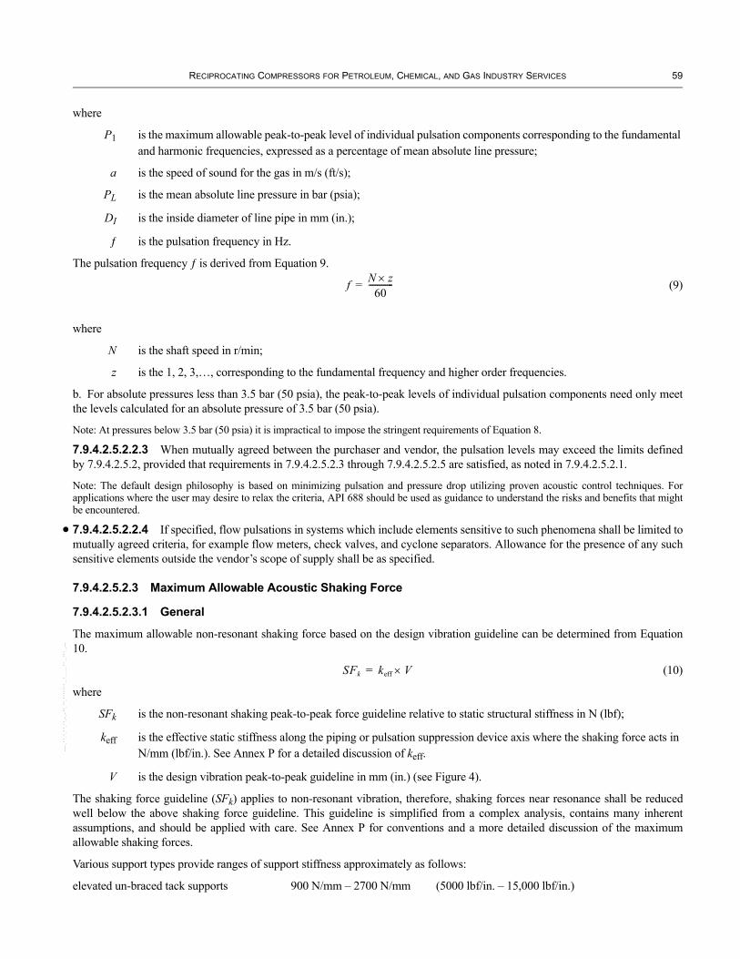
RECIPROCATING COMPRESSORS FOR PETROLEUM, CHEMICAL, AND GAS INDUSTRY SERVICES 59
where
P1 is the maximum allowable peak-to-peak level of individual pulsation components corresponding to the fundamental and harmonic frequencies, expressed as a percentage of mean absolute line pressure;
a is the speed of sound for the gas in m/s (ft/s);
PL is the mean absolute line pressure in bar (psia);
DI is the inside diameter of line pipe in mm (in.);
ƒ is the pulsation frequency in Hz.
The pulsation frequency ƒ is derived from Equation 9.
f N z×60
------------= (9)
where
N is the shaft speed in r/min;
z is the 1, 2, 3,…, corresponding to the fundamental frequency and higher order frequencies.
b. For absolute pressures less than 3.5 bar (50 psia), the peak-to-peak levels of individual pulsation components need only meet the levels calculated for an absolute pressure of 3.5 bar (50 psia).
Note: At pressures below 3.5 bar (50 psia) it is impractical to impose the stringent requirements of Equation 8.
7.9.4.2.5.2.2.3 When mutually agreed between the purchaser and vendor, the pulsation levels may exceed the limits defined by 7.9.4.2.5.2, provided that requirements in 7.9.4.2.5.2.3 through 7.9.4.2.5.2.5 are satisfied, as noted in 7.9.4.2.5.2.1.
Note: The default design philosophy is based on minimizing pulsation and pressure drop utilizing proven acoustic control techniques. For applications where the user may desire to relax the criteria, API 688 should be used as guidance to understand the risks and benefits that might be encountered.
7.9.4.2.5.2.2.4 If specified, flow pulsations in systems which include elements sensitive to such phenomena shall be limited to mutually agreed criteria, for example flow meters, check valves, and cyclone separators. Allowance for the presence of any such sensitive elements outside the vendor’s scope of supply shall be as specified.
7.9.4.2.5.2.3 Maximum Allowable Acoustic Shaking Force
7.9.4.2.5.2.3.1 General
The maximum allowable non-resonant shaking force based on the design vibration guideline can be determined from Equation 10.
SFk keff V×= (10)
where
SFk is the non-resonant shaking peak-to-peak force guideline relative to static structural stiffness in N (lbf);
keff is the effective static stiffness along the piping or pulsation suppression device axis where the shaking force acts in N/mm (lbf/in.). See Annex P for a detailed discussion of keff.
V is the design vibration peak-to-peak guideline in mm (in.) (see Figure 4).
The shaking force guideline (SFk) applies to non-resonant vibration, therefore, shaking forces near resonance shall be reduced well below the above shaking force guideline. This guideline is simplified from a complex analysis, contains many inherent assumptions, and should be applied with care. See Annex P for conventions and a more detailed discussion of the maximum allowable shaking forces.
Various support types provide ranges of support stiffness approximately as follows:
elevated un-braced tack supports 900 N/mm – 2700 N/mm (5000 lbf/in. – 15,000 lbf/in.)
•
--``,,,``,,`````,``,,,,,,,`,,`,,-`-`,,`,,`,`,,`---

60 API STANDARD 618
grade level typical supports and clamps 2700 N/mm – 27,000 N/mm (15,000 lbf/in. – 150,000 lbf/in.)
grade level heavy supports and clamps 27000 N/mm – 45,000 N/mm (150,000 lbf/in. – 250,000 lbf/in.)
7.9.4.2.5.2.3.2 Maximum Allowable Piping System Non-resonant Acoustic Shaking Force
The maximum allowable piping non-resonant shaking forces shall be the lower of the values calculated from Equation 10 or from Equation 11.
In SI units
SFpmax 45 NPS×= (11)
In USC units
SFpmax 250 NPS×=
where
SFpmax is the maximum piping non-resonant shaking peak-to-peak force guideline based on support strength N (lbf);
NPS is the nominal pipe size in mm. (in.).
7.9.4.2.5.2.3.3 Maximum Allowable Cylinder Mounted Pulsation Suppression Device Non-resonant Shaking Force
The maximum allowable non-resonant shaking forces for cylinder mounted pulsation suppression devices shall be the lower of the values calculated from Equation 10 or from Equation 12. For Design Approach 2, since the shaking force levels are not evaluated using Equation 10, the maximum allowable level shall be 10% of Equation 12. For frequencies within ±20% of the calculated pulsation suppression device mechanical natural frequency, the maximum allowable level shall be 1% of Equation 12.
In SI units
SFdmax 45000= (12)
In USC units
SFdmax 10000=
where
SFdmax is the maximum pulsation suppression device non-resonant shaking peak-to-peak force guideline based on structural strength in N (lbf).
Note: The shaking force criteria are intended as design criteria for shaking forces that act along the pulsation suppression device axis. Other shaking forces that can be affected by the pulsation suppression device design such as (but not limited to) those acting parallel to the compressor cylinder nozzles and those acting within the cylinder internal passages must also be evaluated. The evaluation criterion relative to the cylinder varies and should be mutually agreed upon by the purchaser and compressor manufacturer.
7.9.4.2.5.2.4 Piping Design Vibration Criteria
The predicted piping vibration magnitude shall be limited to the design level in Figure 4. The diagram in Figure 4 is based on the following:
a. a constant allowable vibration amplitude of 0.5 mm peak-to-peak (20 mils peak-to-peak) for frequencies below 10 Hz (the frequency of 10 Hz is also according to ISO 10816);b. a constant allowable vibration velocity of approximately 32 mm/s peak-to-peak (1.25 in./s peak-to-peak) for frequencies between 10 and 200 Hz.
The limits in Figure 4 are intended as a design trigger point for analysis in accordance with 7.9.4.2.5.2.1. These values should not be used as field acceptance criteria.
Note: The requirements in this subclause are considered to be conservative. There are however situations in which high stress risers and un-braced small diameter attached piping can pose a problem even though the main pipe exhibits acceptable vibration limits. There are no criteria conservative enough to be used without a significant understanding of vibrational mechanics.
--``,,,``,,`````,``,,,,,,,`,,`,,-`-`,,`,,`,`,,`---

RECIPROCATING COMPRESSORS FOR PETROLEUM, CHEMICAL, AND GAS INDUSTRY SERVICES 61
•
Figure 4—Piping Design Vibration at Discrete Frequencies
7.9.4.2.5.2.5 Maximum Allowable Cyclic Stress
7.9.4.2.5.2.5.1 For Design Approach 3, Steps 3b1 and 3b2, pulsation and/or mechanically induced vibration shall not cause a cyclic stress level in the piping and pulsation suppression devices in excess of the endurance limits of materials used for components subject to these cyclic loads. For example, for carbon steel pipe with an operating temperature below 370°C (700°F), the peak-to-peak cyclic stress range shall be less than 180 N/mm2 (26,000 psi) considering all stress concentration factors present and with all other stresses within applicable code limits.
It is not considered necessary to demonstrate compliance with this clause for Design Approaches 1 and 2.
7.9.4.2.5.2.5.2 If specified, a piping system flexibility analysis that predicts forces and stresses resulting from thermal gradients, thermal transients, pipe and fitting weights, static pressure, and bolt-up strains shall be performed. The specified piping code shall provide the design criteria.
Modeling should include frame growth and component properties.
7.9.4.2.5.3 Other Criteria
7.9.4.2.5.3.1 Maximum Allowable Pressure Drop
For all design approaches:
a. Unless otherwise specified, the pressure drop for each operating case, based on steady flow through a pulsation suppression device at the manufacturer’s rated capacity, shall not exceed 0.25% of average absolute line pressure at the device, or the value determined by Equation 13, whichever is higher. These limits shall be increased by a factor of two when the pressure drop is calculated using the total flow, where total flow is the sum of the steady flow plus dynamic flow components, provided that the static component still meets the above criteria.
PΔ 1.67 R 1–R
------------⎝ ⎠⎛ ⎞ %= (13)
where
P is the maximum pressure drop based on steady flow through a pulsation suppression device expressed as a percentage of mean absolute line pressure at the inlet of the device;
R is the stage pressure ratio.
b. When a moisture separator is an integral part of the pulsation suppression device, the pressure drop for each operating case, based on steady flow through such a device at the manufacturer’s rated capacity, shall not exceed 0.33% of the mean absolute line pressure at the device, or the percentage determined by Equation 14, whichever is higher. These limits shall be increased by a
--``,,,``,,`````,``,,,,,,,`,,`,,-`-`,,`,,`,`,,`---

62 API STANDARD 618
factor of two when the pressure drop is calculated using the total flow, where total flow is the sum of the steady flow plus dynamic flow components.
ΔP 2.17 R 1–R
------------⎝ ⎠⎛ ⎞ %= (14)
c. Pressure drops specified in this clause may be exceeded by mutual agreement between purchaser and vendor, when this is the consequence of the preferred solution to piping resonance problems. The effects of dynamic interaction between compressor cylinders, pulsation suppression devices and attached piping on cylinder performance are evaluated and pulsation-induced power and capacity deviations are determined for the recommended design. This analysis should optimize pulsation related compressor performance.
7.9.4.2.5.3.2 Separation Margins
Unless otherwise specified, both of the following guidelines are to be used together to avoid coincidence of excitation frequencies with mechanical natural frequencies of the compressor, pulsation suppression devices and piping system.
a. The minimum mechanical natural frequency of any compressor or piping system element shall be designed to be greater than 2.4 times maximum rated speed.
Note 1: The intent is to be above twice running speed, because there is almost always sufficient excitation energy at the first and second orders to excite resonances to a dangerous level.
Note 2: In certain compressor configurations, there can be significant excitation energy at higher orders of running speed and the system design shall take this into account. When the minimum mechanical natural frequency guideline is not met or when there is significant excitation energy at higher orders, the separation margins as defined in b) shall be maintained.
b. The predicted mechanical natural frequencies shall be designed to be separated from significant excitation frequencies by at least 20%.
Note: The intent is that at least 10% separation for the actual system is achieved, and due to modeling limitations, if 20% is used for predicted designs then 10% for the actual system will generally be attained.
Note 2: The ability to accurately predict resonance, and therefore separation margin, is greatly effected by the stiffness of the system. Elevated rack-mounted piping systems will be inherently less stiff than grade-mounted pipe on concrete sleepers. In general, the stiffer the system, the lower the sensitivity of the model to stiffness variability, and therefore the more accurate the prediction of the natural frequencies and avoidance of coincidence with excitation frequencies.
7.9.4.2.5.3.3 Flow Measurement Error
Unless otherwise specified, for flow meters located in the specified piping system, the maximum flow measurement error caused by pulsation shall not exceed the following:
a. For Non-custody Transfer meters: 1.00% error. b. For Custody Transfer meters: 0.125% error.
Note: See API 688 for a discussion on flow measurement error.
7.9.4.2.6 Documentation Requirements
A written report on the control of pulsation and vibration shall be furnished to the purchaser. Compliance with the requirements of 7.9 for the specified design approach shall be documented. The report shall define the analysis scope, including analysis guidelines, compressor configuration, load steps, gas composition, and extent of the piping system analyzed. The report shall include the recommendations resulting from the analysis. The documentation shall also present results applicable to each type of analysis performed. Acoustic simulation results include cylinder nozzle and piping pulsation, acoustic shaking forces and flow pulsation at equipment sensitive to this in spectrum form. Separation Margin analysis results includes natural frequencies and mode shapes. Forced mechanical response results include vibration and cyclic stress. The format of the results presentation should permit easy comparison with the analysis guidelines.
--``,,,``,,`````,``,,,,,,,`,,`,,-`-`,,`,,`,`,,`---

RECIPROCATING COMPRESSORS FOR PETROLEUM, CHEMICAL, AND GAS INDUSTRY SERVICES 63
•
•
•
•
7.9.5 Pulsation Suppression Devices
7.9.5.1 General
7.9.5.1.1 As a minimum, pulsation suppression equipment shall be designed and fabricated in accordance with the specified pressure vessel code. If specified, the pulsation suppressors shall be stamped with the symbol as required by the specified pressure vessel code (e.g. ASME Code) and registered with the required jurisdiction.
7.9.5.1.2 The maximum allowable working pressure for any component shall not be less than the set pressure of the relief valve serving that component and, in any case, shall not be less than a gauge pressure of 4 bar (60 psig).
CAUTION: Purchasers should be aware of the overpressure hazards of closing suction block valves on idle compressors. Suction-side equipment between the block valve and the compressor cylinder should be rated for discharge pressure or have a protective relief valve.
7.9.5.1.3 All materials in contact with process gases shall be compatible with the gases being handled. The corrosion allowance for shells and internals of carbon-steel pulsation suppression equipment shall be a minimum of 3 mm (1/8 in.) unless otherwise specified on the data sheet.
Regardless of materials, all shells, heads, baffles, and partitions shall have a minimum thickness of 10 mm (3/8 in.). Welding procedures shall be provided (see Vendor Data section in Annex F, Item 17).
7.9.5.1.4 • If specified, all butt welds shall be 100% radiographed.
7.9.5.1.5 All flanged branch connections shall be reinforced so that the reinforcement provides a metal area equal to the cut-away area removed from the shell or head regardless of the metal thickness in the branch connection wall. Stress concentration factors shall be considered to assure compliance with 7.9.4.2.5.2.5.
7.9.5.1.6 Suction pulsation suppression devices, not provided with an integral moisture removal section, shall be designed to prevent trapping of liquid.
7.9.5.1.7 If specified, the suction pulsation suppression device(s) shall include a final moisture removal section as an integral part of the vessel. This device shall be equipped as detailed in 7.8.
7.9.5.1.8 The nozzle length from the shell of the pulsation suppression device to the cylinder flange shall be held to a minimum that is consistent with thermal flexibility and pulsation requirements. The nozzle area shall be at least equal to the area for the nominal compressor cylinder flange size. Adequate space shall be allowed for access to and maintenance of the cylinder’s working parts.
7.9.5.1.9 The orientation of the pulsation suppression devices and their nozzles shall be approved by the purchaser. Ratings, types, and arrangements of all connections shall be agreed on by the purchaser and the vendor.
7.9.5.1.10 A DN 20 (3/4 NPS) pressure test connection shall be provided at each pulsation suppressor inlet and outlet nozzle. An external drain connection of at least DN 25, (1 NPS) shall be provided for each compartment where practical. Where multiple drains are impractical, circular notched openings in the baffles that are located at the low point of the vessel wall may be used with the purchaser’s approval. The effect of such drain openings on the performance of the pulsation suppression device must be considered. Arrangement of internals shall ensure that liquids will flow to drain connections under all operating conditions.
7.9.5.1.11 The cylinder nozzle of each discharge pulsation suppression device shall be provided with two connections located to permit, without interference, the purchaser’s installation of thermowells of at least DN 25, (NPS 1) for a high-temperature alarm or shutdown element and a dial thermometer. If specified, a thermowell connection of at least DN 25, (NPS 1) shall also be provided for the cylinder nozzle of each suction pulsation suppressor.
7.9.5.1.12 Flanged connections DN 25, (NPS 1) and smaller, although reinforced in accordance with 7.9.5.1.5, shall be designed to minimize overhung weight and shall be gusseted back to the main pipe or reinforcing pad in at least two planes to avoid breakage resulting from vibration.
7.9.5.1.13 Unless otherwise specified, main connections to the compressor cylinder(s) and to process line shall be weld-neck flanges. For non-standard connections, see 6.8.4.2.1 and 6.8.4.1.12.
7.9.5.1.14 Pulsation suppressors with an internal diameter equal to or greater than 450 mm (18 in.) shall have studded pad-type inspection openings of at least 150 mm (6 in.) in diameter, complete with blind flanges and gaskets to provide access to each
--``,,,``,,`````,``,,,,,,,`,,`,,-`-`,,`,,`,`,,`---

64 API STANDARD 618
•
•
•
•
compartment. For pulsation suppressors with an internal diameter less than 450 mm (18 in.), 100 mm (4 in.) studded pad-type inspection openings may be used. Inspection openings shall be located in a position that provides maximum visual inspection capability of critical welds such as both sides of the baffles.
Note: For higher pressure flange ratings, the internal diameter of standard nozzles is less than the nominal sizes shown above. The purchaser should determine if the actual size is adequate to accommodate inspection procedures.
7.9.5.1.15 Unless otherwise specified or approved by the purchaser, pulsation suppression device connections other than those covered by 7.9.5.1.13 and 7.9.5.1.14 shall also be weld neck flanges. When threaded fittings are provided, they shall have a minimum rating of Class 6000.
7.9.5.1.16 Flanges shall be in accordance with ISO 7005-1 or ASME B16.5; however, lap-joint and slip-on flanges shall not be used. The finish of the gasket contact surface for flanged or machined bosses, other than the ring joint type shall be between 3.2 µm and 6.4 µm (125 µin and 250 µin.) arithmetic average roughness (Ra). Either a serrated-concentric finish or a serrated-spiral finish having a pitch in the range of 0.6 mm – 1.0 mm (24 grooves/in. – 40 grooves/in.) shall be used. The surface finish of the gasket grooves of ring joint connections shall comply with ASME B16.5.
7.9.5.1.17 If specified, provisions shall be made for attaching insulation. All connections and nameplates shall be arranged to clear the insulation.
7.9.5.1.18 All internals of pulsation suppression devices shall be designed, fabricated, and supported considering the possibility of high acoustic shaking forces. Dished baffles in lieu of flat baffles shall be used. The same welding procedures as applicable to external welds shall be followed. Full penetration welds shall be used for the attachment of the baffles to the pulsation suppressor shell.
7.9.5.1.19 All butt welds shall be full penetration welds.
7.9.5.1.20 If specified, internal surfaces of carbon steel pulsation suppression devices shall be covered with a coating of phenolic or vinyl resins that are suitable for the service conditions.
7.9.5.1.21 A stainless steel nameplate shall be provided on each pulsation suppression device. The manufacturer’s standard data, purchaser’s equipment item number and purchase order number shall be included.
7.9.5.1.22 If specified, the dynamic and static stresses on the pulsation suppression device internals that result from pulsation-induced shaking forces and pressure-induced static forces shall be analyzed to confirm compliance with 7.9.4.2.4.
7.9.5.1.23 If required by the specified pressure vessel code, such as ASME Section 8, Division 2, a low cycle fatigue analysis shall be performed to predict the stresses from thermal gradients, thermal transients, and pressure cycles on the pulsation suppression devices and internal components.
7.9.5.2 Fabrication and Thermally Induced Stresses in the Pulsation Suppression Device
7.9.5.2.1 Manufacturing tolerances and fit-up procedures for pulsation suppression devices, compressor cylinder nozzle connections and line connections, shall be adequate to allow bolting of flanges without strain which may result in excessive nozzle stresses, changes to component alignment or changes to rod runout. When two or more cylinders are to be connected to the same pulsation suppression device, the flanges shall be fitted up to aligned cylinders at the compressor vendor’s shop and welded in place to assure proper final alignment and to minimize residual stresses. This procedure is especially important for ring joint flanges.
Note: An alignment fixture may be necessary on larger, block-mounted units.
7.9.5.2.2 The forces induced by thermal expansion of the pulsation suppression devices shall be taken into account to avoid intolerable misalignment and excessive stresses during operation.
7.9.6 Supports for Pulsation Suppression Devices If specified, supports for the pulsation suppression devices and vendor-supplied piping shall be furnished by the vendor. The supports shall be designed considering static loading (including piping loads), acoustic shaking forces, and mechanical responses; and shall not impose harmful stresses on the compressor, piping system, or pulsation suppression devices to which they are attached. In calculating stress levels, the compressor frame growth and the flexibilities of the frame, crosshead guide, distance piece, flange, and branch connection shall be considered. Compliant (resilient) supports having inherent vibratory dampening
--``,,,``,,`````,``,,,,,,,`,,`,,-`-`,,`,,`,`,,`---

RECIPROCATING COMPRESSORS FOR PETROLEUM, CHEMICAL, AND GAS INDUSTRY SERVICES 65
•
•
characteristics are preferred as they accommodate thermal expansion. Loading of compliant supports shall be adjustable. Noncompliant supports shall be designed to allow adjustment by the purchaser while in operation. Spring supports shall not be used unless specifically approved by the purchaser.
Note: To the extent possible, the foundation of the supports should be integral with the compressor foundation. When noncompliant adjustable supports are used, they should be adjusted by the purchaser at normal operating conditions.
7.10 AIR INTAKE FILTERS
7.10.1 • For air compressors taking suction from the atmosphere, a dry-type air intake filter-silencer suitable for outdoor mounting shall be provided by the vendor, unless otherwise specified. Special design details, if any, shall be as specified by the purchaser. The vendor shall bring to the purchaser’s attention any hazards that he believes could result from complying with the purchaser’s specification.
7.10.2 As a minimum, the following features shall be considered in the design of the filter-silencer:
a. micron particle rating;b. ease of cleaning during in-service conditions;c. corrosion protection of filter and of internal surfaces of inlet piping;d. avoidance of internal threaded fasteners;e. connections for measuring pressure differential across the filter.
7.11 SPECIAL TOOLS
7.11.1 When special tools and fixtures are needed to disassemble, assemble or maintain the unit, they shall be included in the quotation and furnished as part of the initial supply of the machine, together with complete instructions for their use. For multiple-unit installation, the quantities of special tools and fixtures shall be agreed by the purchaser and the vendor. These or similar special tools shall be used during shop assembly and post-test disassembly of the equipment.
7.11.2 Special tools for reciprocating compressors shall include, as a minimum:
a. mandrels for fitting solid wear bands on non-segmental pistons;b. a lifting and lowering device for removal and insertion of valve assemblies with a mass greater than 15 kg (33 lb);c. a crosshead removal and installation tool;d. sleeve/cone to enable piston rod to be passed through completely assembled packing (see 6.13.1.7);e. if specified, hydraulic tensioning tools.
7.11.3 When special tools are provided, they shall be packaged in separate, rugged metal box or boxes and marked “special tools for (tag/item number).” Each tool shall be stamped or tagged to indicate its intended use.
7.11.4 All compressors shall be provided with suitable means of barring for maintenance. For compressors with a rated power equal to or greater than 750 kW (1000 hp), and for compressors with a peak bar-over torque requirement equal to or greater than 1600 Newton-meters (1200 ft-lb), a power driven barring device shall be furnished. The vendor shall furnish a complete description of the barring device including, such factors as method of operation (for example, manual engagement and automatic disengagement on start of compressor), lockout signals required, location, guards and power required.
7.11.5 • If specified, each compressor shall be fitted with a device to lock the shaft in position during maintenance. The device shall allow locking of the shaft in multiple positions, as necessary for maintenance. The device shall be fitted with a limit switch.
Note: The purchaser should interlock this limit switch with the driver.
8 Inspection and Testing8.1 GENERAL
8.1.1 The extent of the purchaser’s participation in the inspection and testing shall be as specified.
8.1.2 If specified, the purchaser's representative, the vendor's representative or both shall indicate compliance in accordance with the inspector's checklist (Annex K) by initialing, dating and submitting the completed checklist to the purchaser before shipment.
--``,,,``,,`````,``,,,,,,,`,,`,,-`-`,,`,,`,`,,`---

66 API STANDARD 618
•
•
•
•
--``,,,``,,`````,``,,,,,,,`,,`,,-`-`,,`,,`,`,,`---
8.1.3 After advance notification to the vendor, the purchaser's representative shall have entry to all vendor and sub-vendor plants where manufacturing, testing or inspection of the equipment is in progress.
8.1.4 The vendor shall notify sub-vendors of the purchaser's inspection and testing requirements.
8.1.5 The vendor shall provide sufficient advance notice to the purchaser before conducting any inspection or test that has been specified to be witnessed or observed.
8.1.6 The amount of advanced notification required for a witnessed or observed inspection or test shall be as specified. Five working days are usually considered adequate notice for inspections and tests. An observed test shall not be conducted until the specified time.
Note: For an observed test, the purchaser should expect to be in the factory longer than is required for a witnessed test.
8.1.7 When shop inspection and testing have been specified, the purchaser and the vendor shall coordinate manufacturing hold points and inspectors' visits.
8.1.8 Prior to a witnessed mechanical running or performance test, confirmation of the successful completion of the applicable preliminary test shall be provided.
8.1.9 Equipment, materials and utilities for the specified inspections and tests shall be provided by the vendor.
8.1.10 The purchaser's representative shall have access to the vendor's quality program for review.
8.2 INSPECTION
8.2.1 General
8.2.1.1 The vendor shall keep the following data available for at least 20 years:
a. necessary or specified certification of materials, such as mill test reports;b. test data and results to verify that the requirements of the specification have been met;c. fully identified records of all heat treatment whether in the normal course of manufacture or as part of a repair procedure;d. results of quality control tests and inspections;e. details of all repairs;f. if specified, final assembly maintenance and running clearances;g. other data specified or required by applicable codes and regulations (see 5.2 and 9.3.1.1).
8.2.1.2 Pressure-containing parts shall not be painted until the specified inspection and testing of the parts is complete.
8.2.1.3 In addition to the requirements of 6.15.7.1, the purchaser may specify the following:
a. parts that shall be subjected to surface and subsurface examination;b. the type of examination required, such as magnetic particle, liquid penetrant, radiographic and ultrasonic examination.
8.2.2 Material Inspection
8.2.2.1 General
8.2.2.1.1 When radiographic ultrasonic, magnetic particle or liquid penetrant inspection of welds or materials is required or specified, the criteria in 8.2.2.2 through 8.2.2.5 shall apply unless other corresponding procedures and acceptance criteria have been specified. Cast iron may be inspected only in accordance with 8.2.2.4 and/or 8.2.2.5. Welds, cast steel, and wrought material shall be inspected in accordance with 8.2.2.2 through 8.2.2.5.
8.2.2.1.2 The vendor shall review the design of the equipment and impose more stringent criteria than the generalized limits required in 8.2.2, if appropriate.
8.2.2.1.3 Defects that exceed the limits imposed in 8.2.2 shall be removed to meet the quality standards cited, as determined by the inspection method specified.
Note: Care should be taken in the use of acceptance criteria for iron castings. Criteria developed for other materials are often not applicable.

RECIPROCATING COMPRESSORS FOR PETROLEUM, CHEMICAL, AND GAS INDUSTRY SERVICES 67
•
•
•
8.2.2.2 Radiography
8.2.2.2.1 Radiography shall be performed in accordance with ASTM E 94.
8.2.2.2.2 The acceptance standard used for welded fabrications shall be the specified pressure code or ASME Section VIII, Division 1, UW-51 (for 100% radiography) and UW-52 (for spot radiography). The acceptance standard used for castings shall be the specified pressure code or ASME Section VIII, Division 1, Appendix 7.
8.2.2.3 Ultrasonic Inspection
8.2.2.3.1 Ultrasonic inspection shall be in accordance with the specified pressure code or ASME Section V, Articles 5 and 23.
8.2.2.3.2 The acceptance standard used for welded fabrications shall be the specified pressure code or ASME Section VIII, Division 1, Appendix 12. The acceptance standard used for castings shall be the specified pressure code or ASME Section VIII, Division 1, Appendix 7.
The acceptance criteria for steel forgings shall be determined by the manufacturer in accordance with ASTM A 388M.
8.2.2.3.3 All crankshafts shall be ultrasonically tested in accordance with ASTM A 503 after machining, but before drilling.
8.2.2.4 Magnetic Particle Inspection
8.2.2.4.1 Both wet and dry methods of magnetic particle inspection shall be performed in accordance with ASTM E 709.
8.2.2.4.2 The acceptance standard used for welded fabrications shall be the specified pressure code or ASME Section VIII, Division 1, Appendix 6 and Section V, Article 25. The acceptability of defects in castings shall be based on a comparison with the photographs in ASTM E 125. For each type of defect, the degree of severity shall not exceed the limits specified in Table 7.
Table 7—Maximum Severity of Defects in Castings
Type Defect Maximum Severity LevelI Linear discontinuities 1II Shrinkage 2III Inclusions 2IV Chills and chaplets 1V Porosity 1VI Welds 1
8.2.2.5 Liquid Penetrant Inspection
8.2.2.5.1 Liquid penetrant inspection shall be in accordance with the specified pressure code or with ASME Section V, Article 6 (see ASTM E 165).
8.2.2.5.2 The acceptance standard used for welded fabrications shall be the specified pressure code or ASME Section VIII, Division 1, Appendix 8 and Section V, Article 24. The acceptance standard used for castings shall be the specified pressure code or ASME Section VIII, Division 1, Appendix 7.
8.2.3 Mechanical Inspection
8.2.3.1 During assembly of the equipment, all components (including integrally cast-in passages and all piping and appurtenances) shall be inspected to ensure they have been cleaned and are free of foreign materials, corrosion products and mill scale.
8.2.3.2 When the oil system is specified to be run in the manufacturer’s shop, (see 6.14.2.1.10) it shall meet the test screen cleanliness requirements specified in ISO 10438-1 or API 614, Chapter 1, and ISO 10438-3 or API 614, Chapter 3.
8.2.3.3 If specified, the purchaser may inspect the equipment and all piping and appurtenances for cleanliness before heads are welded onto vessels, openings in vessels or exchangers are closed or piping is finally assembled.
8.2.3.4 If specified, the hardness of parts, welds and heat affected zones shall be verified as being within the allowable values by testing. The method, extent, documentation and witnessing of the testing shall be mutually agreed by the purchaser and the vendor.
--``,,,``,,`````,``,,,,,,,`,,`,,-`-`,,`,,`,`,,`---

68 API STANDARD 618
--``,,,``,,`````,``,,,,,,,`,,`,,-`-`,,`,,`,`,,`---
8.2.3.5 Unless otherwise specified, the equipment components or surfaces subject to corrosion shall be coated with the vendor’s standard rust preventive immediately after inspection. Temporary rust preventive shall be easily removable with common petroleum solvents. The equipment shall be closed promptly upon the purchaser’s acceptance thereof. See 8.4.3 for details.
8.3 TESTING
8.3.1 General
8.3.1.1 Equipment shall be tested in accordance with 8.3.2 and 8.3.3. Other tests that can be specified are described in 8.3.4.
8.3.1.2 At least six weeks before the first scheduled running test the vendor shall submit to the purchaser, for his review and comment, detailed procedures for the mechanical running test and all specified running optional tests (8.3.4) including acceptance criteria for all monitored parameters.
8.3.1.3 The vendor shall notify the purchaser not less than five working days before the date that the equipment will be ready for testing. If the testing is rescheduled, the vendor shall notify the purchaser not less than 5 working days before the new test date.
8.3.2 Hydrostatic and Gas Leakage Tests
8.3.2.1 Pressure-containing parts (including auxiliaries) shall be tested hydrostatically with liquid at a higher temperature than the nil-ductility transition temperature of the material being tested and at the following minimum test pressures:
a. cylinder gas passages and bore: 11/2 times maximum allowable working pressure, but not less than a gauge pressure of 1.5 bar (20 psig);b. cylinder cooling jackets and packing cases: 11/2 times maximum allowable working pressure;c. piping, pressure vessels, filters and other pressure-containing components: 11/2 times maximum allowable working pressure or in accordance with the specified pressure code, but not less than a gauge pressure of 1.5 bar (20 psig).
The tests specified in Items a and b shall be performed prior to the installation of the cylinder liner.
Compressor cylinders shall be tested as assembled components using the heads, valve covers, clearance pockets, and fasteners to be supplied with the finished cylinder.
Note: For gas pressure-containing parts, the hydrostatic test is a test of the mechanical integrity of the component and is not a valid gas leakage test.
8.3.2.2 The following gas test shall be performed to ensure that the components do not leak process gas. The leakage tests shall be conducted with the components thoroughly dried and unpainted. Compressor cylinders shall be leak-tested without liners, but with the following job components: heads, valve covers, clearance pockets and fasteners.
a. Pressure-containing parts such as compressor cylinders and clearance pockets handling gases with a molar mass equal to or less than 12 or gases containing a mol percentage of H2S equal to or greater than 0.1%, shall undergo, in addition to the hydrostatic test specified in 8.3.2.1, a pressure test with helium performed at the maximum allowable working pressure. Leak detection shall be by helium probe or by submergence in water. The water shall be at a higher temperature than the nil-ductility transition temperature of the material being tested. The internal pressure shall be maintained, while submerged, at the maximum allowable working pressure. Zero leakage is required (see 8.3.2.6). In the case of testing by helium probe, the procedure, the sensitivity of the instrument and the acceptance criteria shall be by prior agreement between the purchaser and the vendor.b. Cylinders handling gases other than those described above in Item a shall undergo a gas leakage test as described in Item a, with either air or nitrogen used as the test gas.
8.3.2.3 If the part tested is expected to operate at a temperature at which the strength of a material is below the strength of that material at the testing temperature, the hydrostatic test pressure shall be multiplied by a factor obtained by dividing the allowable working stress for the material at the testing temperature by that at the rated operating temperature. For piping, the stress values used shall be those given in ASME B31.3. For vessels, the stress values used shall be those in the specified pressure code or in ASME Section VIII, Division 1 for vessels. The pressure obtained from the aforementioned calculation shall then be used as the minimum pressure at which the hydrostatic test is performed. The data sheets shall list actual hydrostatic test pressures.
Note: The applicability of this requirement to the material being tested should be verified before hydrostatic test, as the properties of many grades of steel do not change appreciably at temperatures up to 200ºC (400ºF).

RECIPROCATING COMPRESSORS FOR PETROLEUM, CHEMICAL, AND GAS INDUSTRY SERVICES 69
•
•
•
•
8.3.2.4 Where applicable, tests shall be in accordance with the standard used to design the part. In the event that a discrepancy exists between the test pressure in the standard used to design the part and the test pressure in this standard, the higher pressure shall be used.
8.3.2.5 The chlorine content of liquids used to test austenitic stainless steel materials shall not exceed 50 ppm. To prevent deposition of chlorides on austenitic stainless steel as a result of evaporative drying, all residual liquid shall be removed from tested parts at the conclusion of the test.
Note: Chloride content is limited in order to prevent stress corrosion cracking.
8.3.2.6 Test duration shall be sufficient to allow complete examination of parts under pressure. The hydrostatic and gas leakage tests shall be considered satisfactory when neither leaks nor seepage through the pressure containing parts or joints is observed for a minimum of 30 minutes. Large, heavy pressure containing parts of complex systems can require a longer testing period to be agreed upon by the purchaser and the vendor. Seepage past internal closures required for testing of segmented cases and operation of a test pump to maintain pressure are acceptable.
8.3.2.7 Test gaskets shall be identical to those required for the service conditions.
8.3.3 Mechanical Running Test
8.3.3.1 All compressors, drivers, and gear units shall be shop tested in accordance with the vendor’s standard.
8.3.3.2 If specified, the shop test of the compressor shall comprise a 4-hour unloaded running test.
8.3.3.3 • If specified, packaged units, including integral auxiliary system packages, shall undergo a 4-hour mechanical running test prior to shipment. The test shall prove mechanical operation of all auxiliary equipment, as well as the compressor, reduction gear, if any, and driver as a complete unit.
The compressor need not be pressure-loaded for this test. The procedure for this running test shall be agreed upon by the purchaser and the vendor.
8.3.3.4 All oil pressures, viscosities, and temperatures shall be within the range of operating values recommended in the vendor's operating instructions for the specific unit being tested.
8.3.3.5 If replacement or modification of bearings, or dismantling to replace or modify other parts are required to correct mechanical or performance deficiencies, the initial test shall be deemed not acceptable and the final shop tests shall be run after these deficiencies are corrected.
8.3.3.6 Auxiliary equipment not integral with the unit, such as auxiliary oil pumps, oil coolers, filters, intercoolers and aftercoolers need not be used for any compressor shop tests unless specified. If specified, auxiliary system consoles shall receive both an operational test and a 4-hour mechanical running test prior to shipment. The procedure for this running test shall be as agreed upon by the purchaser and the vendor.
8.3.3.7 The purchaser shall specify if dismantling for inspection (other than that required by evidence of malfunctioning during testing) is required.
8.3.4 Other Tests
8.3.4.1 A bar-over test of the frame and cylinders shall be made in the vendor’s shop to verify piston end clearances and rod runout. The final bar-over test shall be performed with all compressor cylinder valves in place to demonstrate no piston interference. Vertical and horizontal piston-rod runout (cold) at packing case flanges shall also be measured during this test (see 6.3.1 and 6.10.4.6). Bar-over test results shall become a part of the purchaser’s records (Annex F, Item 59).
8.3.4.2 If specified, all machine-mounted equipment, prefabricated piping and appurtenances furnished by the vendor shall be fitted and assembled in the vendor’s shop. The vendor shall be prepared to demonstrate that the equipment is free of harmful strains.
8.3.4.3 All compressor suction and discharge cylinder valves shall be leak-tested in accordance with the vendor’s standard procedure.
8.3.4.4 • If specified, the compressor shall be subject to a performance test in accordance with ISO 1217 or the applicable ASME power test code.
--``,,,``,,`````,``,,,,,,,`,,`,,-`-`,,`,,`,`,,`---

70 API STANDARD 618
•
•
8.4 PREPARATION FOR SHIPMENT
8.4.1 Equipment shall be suitably prepared for the type of shipment specified, including blocking of the crankshaft. The preparation shall make the equipment suitable for 6 months of outdoor storage from the time of shipment. If storage for a longer period is specified, the purchaser will consult with the vendor regarding recommended procedures to be followed.
8.4.2 The vendor shall provide the purchaser with the instructions necessary to preserve the integrity of the storage preparation after the equipment arrives at the job site and before start-up, as described in API 686, Chapter 3.
Note: It is recognized that failure to follow these instructions can jeopardize the successful operation of the equipment.
8.4.3 The equipment shall be prepared for shipment after all testing and inspection have been completed and the equipment has been released by the purchaser. The preparation shall include provisions of 8.4.4 through 8.4.18.
8.4.4 Equipment shall be completely free of water prior to any shipment preparation.
8.4.5 Except for machined surfaces, all exterior surfaces that can corrode during shipment, storage or in service, shall be given at least one coat of the manufacturer's standard paint. The paint shall not contain lead or chromates.
Note: Austenitic stainless steels are typically not painted.
8.4.6 Exterior machined surfaces, except for corrosion-resistant material, shall be coated with a rust preventive.
8.4.7 The interior of the equipment, including pulsation suppression devices, shall be clean; free from scale, welding spatter and foreign objects; and sprayed or flushed with a suitable rust preventive that is oil soluble or can be removed with solvent. In lieu of a soluble rust preventive, a permanently applied rust preventive may be used with prior approval by the purchaser.
8.4.8 Internal areas of frames, bearing housings, and oil system equipment such as reservoirs, vessels, and piping shall be coated with an oil-soluble rust preventive or, with the purchaser’s prior approval, a permanent rust preventive.
8.4.9 Any paint exposed to lubricants shall be oil-resistant. When synthetic lubricants are used or specified (6.14.3.1.9), special precautions shall be taken to ensure compatibility with the paint.
8.4.10 Flanged openings shall be provided with metal closures of a thickness equal to or greater than 5 mm (3/16 in.) with elastomer gaskets and at least four full-diameter bolts. For studded openings, all nuts needed for the intended services shall be used to secure closures. Each opening shall be car sealed so that the protective cover cannot be removed without the seal being broken.
8.4.11 Threaded openings shall be provided with steel caps or round-head steel plugs in accordance with ASME B16.11. The caps or plugs shall be of the same material as that of the pressure casing. Nonmetallic (such as plastic) caps or plugs shall not be used.
8.4.12 Openings that have been beveled for welding shall be provided with closures designed to prevent the entrance of moisture and foreign materials and damage to the bevel.
8.4.13 Lifting points and the center of gravity shall be clearly identified on the equipment package. The vendor shall recommend the lifting arrangement.
8.4.14 The equipment shall be packed for domestic or export shipment as specified. Lifting, load-out and handling instructions shall be securely attached to the exterior of the largest package in a well-marked weatherproof container. Where special lifting devices, such as spreader bars, are required, the supply of these shall be subject to agreement. Upright position, lifting points, weight and dimensions shall be clearly marked on each package.
8.4.15 The equipment shall be identified with item and serial numbers. Material shipped separately shall be identified with securely affixed, corrosion-resistant metal tags indicating the item and serial number of the equipment for which it is intended. Crated equipment shall be shipped with duplicate packing lists, one inside and one on the outside of the shipping container.
8.4.16 Any cylinders, heads, packing cases, packing, pistons, rods, crossheads and shoes, crosshead pins, bushings and connecting rods that are dismantled for the purpose of separate shipment, or that are shipped as spare parts, shall be sprayed with rust preventive, wrapped with moisture-proof sheeting and packed to prevent damage in shipment to, or storage at, the job site.
8.4.17 Exposed shafts and shaft couplings shall be wrapped with waterproof moldable waxed cloth or volatile-corrosion-inhibitor paper. The seams shall be sealed with oil proof adhesive tape.
--``,,,``,,`````,``,,,,,,,`,,`,,-`-`,,`,,`,`,,`---

RECIPROCATING COMPRESSORS FOR PETROLEUM, CHEMICAL, AND GAS INDUSTRY SERVICES 71
--``,,,``,,`````,``,,,,,,,`,,`,,-`-`,,`,,`,`,,`---
8.4.18 Exterior surfaces of pulsation suppressors, piping and vessels shall be cleaned free of pipe scale, welding spatter and other foreign objects.
Immediately after cleaning, external surfaces shall be painted with at least one coat of lead and chromate free primer.
8.4.19 Auxiliary piping connections furnished with the purchased equipment shall be impression stamped or permanently tagged to agree with the vendor's connection table or general arrangement drawing. Service and connection designations shall be indicated.
8.4.20 Bearing assemblies shall be fully protected from the entry of moisture and dirt. If volatile-corrosion-inhibitor crystals in bags are installed in large cavities, the bags shall be attached in an accessible area for ease of removal. Where applicable, bags shall be installed in wire cages attached to flanged covers and bag location shall be indicated by corrosion-resistant tags attached with stainless steel wire.
8.4.21 Component parts, loose parts and spare parts associated with a specific major item of equipment shall be individually packed for shipment and shall not be mixed with similar parts associated with another major item of equipment. For example, parts for the compressor shall not be packed together in the same crate with similar parts for the driver.
8.4.22 One copy of the manufacturer's installation instructions shall be packed and shipped with the equipment.
9 Vendor’s Data9.1 GENERAL
9.1.1 VDDR Form
The information to be furnished by the vendor is specified in 9.2 and 9.3. The vendor shall complete and return the Vendor Drawing and Data Requirements (VDDR) form (see Annex F) to the address(es) noted on the inquiry or order. This form shall detail the schedule for transmission of drawings, curves, data and manuals as agreed to at the time of the proposal or order as well as the number and type of copies required by the purchaser.
9.1.2 Data Identification
The data shall be identified on the transmittal (cover) letters and the title blocks or title pages with the following information:
a. purchaser/user’s corporate name;b. job/project number;c. equipment item number and service name;d. inquiry or purchase order number;e. any other identification specified in the inquiry or purchase order;f. vendor’s identifying proposal number, shop order number, serial number or other reference required to completely identify return correspondence.
9.1.3 Coordination Meeting
Unless otherwise agreed, a coordination meeting shall be held, preferably at the vendor’s plant, within 4 – 6 weeks after the purchase commitment. The purchaser and vendor shall jointly agree on an agenda for this meeting which, as a minimum, shall include the following items:
a. purchase order, scope of supply and sub-vendor items (including spare parts);b. review of applicable specifications and previously agreed exceptions to specifications;c. data sheets;d. compressor performance (including operating limitations);e. pulsation suppression devices;f. schematics and bills of material (for major items) of lube-oil systems, cooling systems, distance pieces and similar auxiliaries;g. preliminary physical orientation of the equipment, piping and auxiliary systems;h. drive arrangement and driver details;i. instrumentation and controls;j. scope and detail of pulsation and vibration analysis and control requirements (see Annexes M and N and 7.9.4.1);k. identification of items for stress analysis review by purchaser (see 6.15.5.1);

72 API STANDARD 618
--``,,,``,,`````,``,,,,,,,`,,`,,-`-`,,`,,`,`,,`---
l. inspection, expediting and testing reports;m. details of functional testing;n. other technical items;o. start-up planning and training;p. schedules for (1) transmittal of data, (2) production, (3) testing, and (4) delivery;q. review details of vendor's quality control program.
9.2 PROPOSALS
9.2.1 General
The vendor shall forward the original proposal, with the specified number of copies, to the addressee specified in the inquiry documents. The proposal shall include, as a minimum, the data specified in 9.2.2 through 9.2.4, and a specific statement that the equipment and all its components and auxiliaries are in strict accordance with this standard. If the equipment or any of its components or auxiliaries is not in strict accordance, the vendor shall include a list that details and explains each deviation. The vendor shall provide sufficient detail to enable the purchaser to evaluate any proposed alternative designs. All correspondence shall be clearly identified in accordance with 9.1.2.
9.2.2 Drawings
9.2.2.1 The drawings indicated on the Vendor Drawing and Data Requirements (VDDR) form (see Annex F) shall be included in the proposal. As a minimum, the following shall be included.
a. A general arrangement or outline drawing for each machine train or skid-mounted package, showing overall dimensions, maintenance clearance dimensions, overall weights, erection weights, and the largest maintenance weight for each item. The direction of rotation and the size and location of major purchaser connections shall also be indicated.b. Cross-sectional drawings showing the details of the proposed equipment.c. Schematics of all auxiliary systems, including the lube-oil system, the cooling system, and the distance-piece vent-and-drain system (when supplied). Auxiliary system schematic diagrams shall be marked to show which portions of the system are integral with or mounted on the major equipment and which are separate.d. Sketches showing methods of lifting the assembled machine or machines, packages, and major components and auxiliaries. (This information may be included on the drawings specified in item a. above.)
9.2.2.2 If “typical” drawings, schematics and bills of material are used, they shall be marked up to show the weight and dimension data to reflect the actual equipment and scope proposed.
9.2.3 Technical Data
The data described below shall be included.
a. Copies of the purchaser’s data sheets complete with the vendor’s information required for the proposal and literature to fully describe details of the offering(s).b. The noise data as required by the purchaser in the inquiry. c. A copy of the Vendor Drawing and Data Requirements form (see Annex F) indicating the schedule according to which the vendor agrees to furnish the data requested by the purchaser (see 9.3).d. Net and maximum operating weights, maximum shipping and erection weights with identification of the item and the maximum normal maintenance weight with identification of the item. These data shall be stated individually where separate shipments, packages, or assemblies are involved. Approximate data shall be clearly identified as such. These data shall be entered on the data sheets where applicable.e. For a compressor with a variable-speed drive, the speed range over which the unit can be operated continuously under the specified operating conditions.f. The vendor shall specifically identify volumetric efficiency of the active end of any cylinder if it is less than 40% at any specified operating condition.
Note: Performance predictions with volumetric efficiencies below 40% are often not reliable.
g. A schedule for shipment of the equipment in weeks after receipt of the order.h. A list of major wearing components showing interchangeability with other purchaser units.

RECIPROCATING COMPRESSORS FOR PETROLEUM, CHEMICAL, AND GAS INDUSTRY SERVICES 73
•
•
•
i. A list of “start-up” spares, to include as a minimum, three lube-oil filter cartridge sets, plates and springs for each valve, one set of packing rings for each rod, one set of rings and wear bands for each piston, plus all o-rings and gaskets necessary for a complete change-out of all packing rings, all piston rings and all valves. The vendor shall add any items that his experience indicates are likely to be required on start-up. j. Complete tabulation of utility requirements, such as steam, water, electricity, air, gas and lube oil; including the quantity of lube oil required and the supply pressure, the heat load to be removed by the oil and the nameplate power rating and operating power requirements of auxiliary drivers. Approximate data shall be defined and clearly identified as such. This information shall be entered on the data sheets.k. A description of the tests and inspection procedures of materials in accordance with 8.2.2.l. Complete details of any proposed air-cooled oil cooler.m. A list of spare parts recommended that the purchaser should stock for normal maintenance purpose. (Any special requirements for long term storage shall be as specified).n. An itemized list of the special tools included in the offering.o. A clear description of the metallurgy of all major components of the compressor (see 6.15.1.1 and 6.15.1.2).p. A full description of the standard shop tests identified in 8.3. Special tests as specified shall also be fully described.q. A list of relief valves, specifying those furnished by the vendor, as required by ISO 10438-1 or API 614, Chapter 1.r. A description of the vendor’s intended response to any special requirements, such as those outlined in 6.7.1. s. If specified, a list of similar machines installed and operating under analogous conditions to that proposed.t. Any start-up, shutdown, or operating restrictions required to protect the integrity of the equipment.u. An outline of all necessary special weather and winterizing protection required by the equipment, its auxiliaries and the driver (if furnished by the vendor) for start-up, operation and idleness. The vendor shall list separately the protective items he proposes to furnish.v. Preliminary rod and gas load tabulation in accordance with 6.6.3.
9.2.4 Optional Tests
The vendor shall furnish an outline of the procedures to be used for each of the special or optional tests that have been specified, or have been proposed by the vendor.
9.3 CONTRACT DATA
9.3.1 General
9.3.1.1 Contract data shall be furnished by the vendor in accordance with the agreed VDDR form.
9.3.1.2 Each drawing shall have a title block in the lower right-hand corner with the date of certification, identification data specified in 9.1.2, revision number and data and title. Similar information shall be provided on all other documents including sub-vendor items.
9.3.1.3 The time allowed for the purchaser’s review of vendor’s data shall be as specified and agreed. Purchaser’s review of vendor’s data shall not constitute permission to deviate from any requirements in the order unless specifically agreed upon in writing. After the data have been reviewed and accepted, the vendor shall furnish certified copies in the quantities specified.
Note: The purchaser should promptly review the vendor's data upon receipt.
9.3.1.4 A complete list of vendor data shall be included with the first issue of major drawings. This list shall contain titles, drawing numbers, and a schedule for transmittal of each item listed. This list shall cross-reference data with respect to the VDDR form in Annex F.
9.3.2 Drawings
The drawing(s) furnished shall contain sufficient information so that when combined with the manuals covered in 9.3.7, the purchaser can properly install, operate and maintain the ordered equipment. Drawings shall be clearly legible and reproducible. (8-point minimum font size even if reduced from a larger size drawing). Drawings made specifically for the order shall be identified in accordance with 9.1.2.
--``,,,``,,`````,``,,,,,,,`,,`,,-`-`,,`,,`,`,,`---

74 API STANDARD 618
•
••
9.3.3 Performance Data
9.3.3.1 If specified, the vendor shall submit performance curves or tables of power and capacity versus suction pressure with parameters of discharge pressure, showing the effects of unloading devices and showing any operating limitation and with calculation input and output data identified, all as mutually agreed between the vendor and the purchaser.
9.3.3.2 Rod load and gas load charts for each load step, complete in accordance with 6.6, including inertial forces and rod reversal magnitude and duration shall be furnished.
9.3.3.3 If specified, the vendor shall furnish the data required for independent rod load, gas load, and reversal calculations.
9.3.3.4 If specified, the effect of valve failure on rod loads and reversal shall be calculated and furnished. The required specifics of this study shall be mutually agreed upon by the purchaser and vendor.
9.3.3.5 Curves of starting torque vs. speed shall be furnished for the compressor, for the motor at rated voltage and for the motor at the specified voltage reduction. The curve sheet shall also state separately the (moment of inertia of the motor alone and the resultant moment of inertia of the driven equipment referred to the motor shaft speed plus the calculated time for acceleration to full speed at the specified voltages (see 7.1.2.) and specified operating conditions (see 7.1.1.6 and 7.1.2.1). All curves shall be scaled in finite values. Values expressed in percentage terms alone shall not be provided.
9.3.4 Technical Data
Data shall be submitted in accordance with the VDDR form. The vendor shall provide full information to enable completion of the data sheets, first “as purchased” and then “as built”. This shall be done by correcting and filling out the data sheets and submitting copies.
If any drawing comments or specification revisions lead to a change in the data, the vendor shall reissue data sheets. This will result in reissue of the complete, corrected data sheets by the purchaser as part of the order specifications.
9.3.5 Progress Reports
The vendor shall submit progress reports to the purchaser at intervals specified.
Note: See the description of item 42 in Annex F for content of these reports.
9.3.6 Recommended Spares
9.3.6.1 The vendor shall submit complete parts lists for all equipment and accessories supplied. These lists shall include part names, manufacturers’ unique part numbers, materials of construction (identified by applicable international standards). Each part shall be completely identified and shown on appropriate cross-sectional, assembly-type cutaway or exploded-view isometric drawings. Interchangeable parts shall be identified as such. Parts that have been modified from standard dimensions or finish to satisfy specific performance requirements shall be uniquely identified by part number. Standard purchased items shall be identified by the original manufacturer's name and part number.
9.3.6.2 The vendor shall indicate on each of these complete parts lists all those parts that are recommended as start-up or maintenance spares, and the recommended stocking quantities of each. These should include spare parts recommendations from sub-suppliers that were not available for inclusion in the vendor's original proposal
9.3.7 Installation, Operation, Maintenance and Technical Data Manuals
9.3.7.1 General
The vendor shall provide sufficient written instructions and all necessary drawings to enable the purchaser to install, operate, and maintain all of the equipment covered by the purchase order. This information shall be compiled in a manual or manuals with a cover sheet showing the information listed in 9.1.2, an index sheet, and a complete list of the enclosed drawings by title and drawing number. The manual or manuals shall be prepared specifically for the equipment covered by the purchase order. “Typical” manuals shall not be provided.
9.3.7.2 Installation Manual
All information required for the proper installation of the equipment shall be compiled in a manual that must be issued no later than the time of issue of final certified drawings. The installation manual may be separate from the operating and maintenance
--``,,,``,,`````,``,,,,,,,`,,`,,-`-`,,`,,`,`,,`---

RECIPROCATING COMPRESSORS FOR PETROLEUM, CHEMICAL, AND GAS INDUSTRY SERVICES 75
instructions. The installation manual shall contain information on alignment and grouting procedures, normal and maximum utility requirements, centers of mass, rigging provisions and procedures, and all other installation data. All drawings and data specified in 9.2.2 and 9.2.3 that are pertinent to proper installation shall be included as part of this manual (see description of line item 64 in Annex F).
9.3.7.3 Operating and Maintenance Manuals
A manual containing all required operating and maintenance instructions shall be supplied no later than two weeks after all specified tests have been successfully completed. In addition to covering operation at all specified process conditions, this manual shall also contain separate sections covering operation under any specified extreme environmental conditions (see description of line item 65 in Annex F).
9.3.7.4 Technical Data Manual
The vendor shall provide the purchaser with a technical data manual within 30 days of completion of shop testing (see description of line item 66 in Annex F for minimum requirements of this manual).
--``,,,``,,`````,``,,,,,,,`,,`,,-`-`,,`,,`,`,,`---

--``,,,``,,`````,``,,,,,,,`,,`,,-`-`,,`,,`,`,,`---

--``,,,``,,`````,``,,,,,,,`,,`,,-`-`,,`,,`,`,,`---
Annex A(informative)
Data Sheets
77

--``,,,``,,`````,``,,,,,,,`,,`,,-`-`,,`,,`,`,,`---

RECIPROCATING COMPRESSORS FOR PETROLEUM, CHEMICAL, AND GAS INDUSTRY SERVICES 79
Figure A-1—Reciprocating Compressor Data Sheet (U.S. Customary Units)
JOB NO. ITEM NO.
PURCHASE ORDER NO.
SPECIFICATION NO.
REVISION NO. DATE
PAGE 1 OF 17 BY
1 APPLICABLE TO: PROPOSALS PURCHASE AS BUILT
2 FOR/USER SITE/LOCATION SERVICE NO. REQ'D
3 NOTE: INDICATES INFO. TO BE BY MANUFACTURER BY MANUFACTURER BY MANUFACTURER OR
4 COMPLETED BY PURCH. WITH PROPOSAL AFTER ORDER PURCHASER AS APPLICABLE
5 COMPR. MFGR TYPE MODEL NO(S) SERIAL NO(S)
6 COMPR.THROWS: TOTAL NO. NO. WITH CYLS. NOMINAL FRAME RATING BHP @ RATED R/MIN OF
7 MAX/MIN ALLOWABLE SPEED / r/min
8 DRIVER MFGR. DRIVER NAMEPLATE HP/OPERATING R/MIN /
9 DRIVE SYSTEM: DIRECT COUPLED GEARED & COUPLED V-BELT
10 TYPE OF DRIVER: IND. MOTOR SYN. MOTOR STEAM TURBINE GAS TURBINE ENGINE OTHER
11 CYLINDERS CONSTRUCTION: LUBE NON-LUBE
12
13 MAX ACCEPTABLE AVG PISTON SPEED ft/min
14 OPERATING CONDITIONS (EACH MACHINE)
15 SERVICE OR ITEM NO.
16 STAGE
17 NORM. OR ALT. CONDITION
18 CERTIFIED PT. (X) MARK ONE
19 MOLECULAR WEIGHT
20 CP/CV (K) @ 150°F OR °F
21 INLET CONDITIONS: AT INLET TO: PULSE DEVICES COMPRESSOR CYLINDER FLANGES
22 NOTE: SIDE STREAM TO STAGE(S), THESE INLET PRESS. ARE FIXED
23 PRESSURE (psia) @ PUL. SUPP. INLET
24 PRESSURE (psia) @ CYL. FLANGE
25 TEMPERATURE (°F)
26 REF: SIDE STREAM TEMPS (°F)
27 COMPRESSIBILITY (Zs )
28 INTERSTAGE: INTERSTAGE P INCL: PULSE DEVICES PIPING COOLERS SEPARATORS OTHER
29 P BETWEEN STAGES, %/psi
30 DISCHARGE CONDITIONS: AT OUTLET FROM: PULSE DEVICE COMP. CYL. FLANGES OTHER
31 PRESSURE (psia) @ CYL. FLANGE
32 PRESS. (psia) @ PUL. SUPP. OUTLET
33 TEMP., ADIABATIC, °F
34 TEMP., PREDICTED, °F
35 COMPRESSIBILITY (Z2 ) OR (ZAVG )
36 * CAPACITY AT INLET TO COMPRESSOR, NO NEGATIVE TOLERANCE (-0%)
37 CAPACITY SPECIFIED
38 IS WET DRY
39 MMSCFD/SCFM (14.7 psia & 60°F)
40 * MFGR.'S RATED CAPACITY (AT INLET TO COMPRESSSOR & BHP @ CERTIFIED TOLERANCE OF ±3% FOR CAP. & ±3% FOR BHP)
41 CAPACITY SPECIFIED
42 IS WET DRY
43 INLET VOLUME FLOW (ICFM)
44 MMSCFD/SCFM (14.7 psia & 60°F)
45 BHP/STAGE
46 TOTAL BHP @ COMPRESSOR SHAFT
47 TOTAL HP INCLUDING
48 V-BELT & GEAR LOSSES
49 * CAPACITY FOR NNT REMARKS:
50 MANUFACTURER'S = REQUIRED ÷ 0.97
51 THEREFORE REQUIRED = MFR'S x 0.97
lb/h
lb/h
RECIPROCATING COMPRESSORAPI 618 5TH EDITION DATA SHEET
U.S. CUSTOMARY UNITS
Rev
isio
n--``,,,``,,`````,``,,,,,,,`,,`,,-`-`,,`,,`,`,,`---

80 API STANDARD 618
Figure A-1—Reciprocating Compressor Data Sheet (U.S. Customary Units) (continued)
JOB NO. ITEM NO.
RECIPROCATING COMPRESSOR REVISION DATE
API 618 5TH EDITION DATA SHEET PAGE 2 OF 17 BY
U.S. CUSTOMARY UNITS1 GAS ANALYSIS AT OPERATING CONDITIONS
2 MOLE % (BY VOLUME) ONLY
3 SERVICE/ITEM NO.
4 STAGE
5 NORMAL OR ALT
6 M.W.
7 AIR 28.966
8 OXYGEN O2 32.000
9 NITROGEN N2 28.016
10 WATER VAPOR H2O 18.016
11 CARBON MONOX. CO 28.010
12 CARBON DIOX. CO2 44.010
13 HYDRO. SULFIDE H2S 34.076
14 HYDROGEN H2 2.016
15 METHANE CH4 16.042
16 ETHYLENE C2H4 28.052
17 ETHANE C2H6 30.068
18 PROPYLENE C3H6 42.078
19 PROPANE C3H8 44.094
20 I-BUTANE C4H10 58.120
21 n-BUTANE C4H10 58.120
22 I-PENTANE C5H12 72.146 APPLICABLE SPECIFICATIONS
23 n-PENTANE C5H12 72.146 API 618-RECIPROCATING COMPRESSORS
24 HEXANE PLUS FOR PETROLEUM, CHEMICAL AND GAS
25 AMMONIA NH3 17.031 INDUSTRY SERVICES
26 HYDRO. CHLOR. HCI 36.461 NACE MR-O175 (6.15.1.11)
27 CHLORINE Cl2 70.914
28 CHLORIDES - TRACES
29
30
31
32 CALCULATED MOL WT.
33 Cp/Cv (K) @ 150° OR °F
34 NOTE: IF WATER VAPOR AND/OR CHLORIDES ARE PRESENT, EVEN MINUTE
35 TRACES, IN THE GAS BEING COMPRESSED, IT MUST BE INCLUDED ABOVE.
36 SITE/LOCATION CONDITIONS
37 ELEVATION FT BAROMETER PSIA AMBIENT TEMPS: MAX °F MIN °F
38 MIN DESIGN METAL TEMP °F (6.15.8.1) RELATIVE HUMIDITY: MAX % MIN %
39 COMPRESSOR LOCATION: INDOOR HEATED UNHEATED AT GRADE LEVEL ELEVATED: ft
40 OUTDOOR NO ROOF UNDER ROOF PARTIAL SIDES PLATFORM: ON-SHORE
41 OFF-SHORE WEATHER PROTECTION REQ. TROPICALIZATION REQ.
42 WINTERIZATION REQUIRED
43 UNUSUAL CONDITIONS: CORROSIVES DUST FUMES OTHER
44
45 ELECTRICAL CLASSIFICATIONS
46 HAZARDOUS NON-HAZARDOUS
47 MAIN UNIT CLASS GROUP DIVISION
48 L.O. CONSOLE CLASS GROUP DIVISION
49 CW CONSOLE CLASS GROUP DIVISION
50
51
REMARKS
Rev
isio
n--``,,,``,,`````
,``,,,,,,,`,,`,,-`-`,,`,,`,`,,`---
RECIPROCATING COMPRESSORS FOR PETROLEUM, CHEMICAL, AND GAS INDUSTRY SERVICES 81
Figure A-1—Reciprocating Compressor Data Sheet (U.S. Customary Units) (continued)
JOB NO. ITEM NO.
RECIPROCATING COMPRESSOR REVISION DATE
API 618 5TH EDITION DATA SHEET PAGE 3 OF 17 BY
U.S. CUSTOMARY UNITS1 PART LOAD OPERATING CONDITIONS
2 CAPACITY CONTROL BY: MFG'S CAP. CONTROL PURCHASERS BY-PASS BOTH OTHER
3 FOR: PART LOAD COND. START-UP ONLY BOTH
4 WITH: AUTO LOADING DELAY INTERLOCK (7.6.2.4) AUTO IMMEDIATE UNLOADING
5 USING: FIXED VOLUME POCK. SUCTION VALVE UNLOADERS: FINGER PLUG OTHER
6 ACTION: DIRECT (AIR-TO-UNLOAD) REVERSE (AIR-TO-LOAD/FAIL SAFE)
7 NUMBER OF STEPS: ONE THREE FIVE OTHER
8 RAIN COVER REQUIRED OVER UNLOADERS
9 ALL UNLOADING STEPS BASIS MANUFACTURERS CAPACITY SHOWN ON PAGE 1.
10 INLET AND DISCHARGE PRESSURE ARE AT CYLINDER FLANGES PULSATION SUPPRESSOR FLANGES
11 SERVICE OR ITEM NO.
12 STAGE
13 NORMAL OR ALTERNATE CONDITION
14 PERCENT CAPACITY
15 WEIGHT FLOW, lb/h
16 MMSCFD/SCFM (14.7 psia & 60°F)
17 POCKETS/VALVES OPERATION *
18 POCKET CLEARANCE ADDED %
19 TYPE UNLOADERS, PLUG/FINGER
20 INLET TEMPERATURE, °F
21 INLET PRESSURE, psia
22 DISCHARGE PRESSURE, psia
23 DISCHARGE TEMP., ADIABATIC °F
24 DISCHARGE TEMP., PREDICTED °F
25 VOLUMETRIC EFF.,%HE/%CE
26 CALC. GAS ROD LOAD, lb, C **
27 CALC. GAS ROD LOAD, lb, T **
28 COMB. ROD LOAD, lb, C (GAS & INERTIA)
29 COMB. ROD LOAD, lb, T (GAS & INERTIA)
30 ROD REV., DEGREES MIN @ X-HD PIN ***
31 BHP/STAGE
32 TOTAL BHP @ COMPRESSOR SHAFT
33 TOTAL HP INCL. V-BELT & GEAR LOSSES
34
35 * SHOW OPERATION WITH THE FOLLOWING SYMBOLS:
36 SUCTION VALVE(S) UNLOADED = S
37 HEAD END = HE OR
38 OR PLUS FIXED POCKET OPEN = F
39 CRANK END = CE OR
40 VARIABLE POCKET OPEN = V
41
42 EXAMPLE: HE-F/CE-S = HEAD END FIXED POCKET OPEN / CRANK END SUCTION VALVE(S) UNLOADED.
43 * * C = COMPRESSION T = TENSION *** X - HD = CROSSHEAD
44 MINIMUM PRESSURE REQUIRED TO OPERATE CYLINDER UNLOADING DEVICES, psig
45 CYLINDER UNLOADING MEDIUM: AIR NITROGEN OTHER
46 PRESSURE AVAILABLE FOR CYLINDER UNLOADING DEVICES, MAX/MIN / psig
47 REMARKS, SPECIAL REQUIREMENTS, AND/OR SKETCH
48
49
50
51
Rev
isio
n--``,,,``,,`````,``,,,,,,,`,,`,,-`-`,,`,,`,`,,`---

82 API STANDARD 618
Figure A-1—Reciprocating Compressor Data Sheet (U.S. Customary Units) (continued)
JOB NO. ITEM NO.
RECIPROCATING COMPRESSOR REVISION DATE
API 618 5TH EDITION DATA SHEET PAGE 4 OF 17 BY
U.S. CUSTOMARY UNITS1 SCOPE OF BASIC SUPPLY
2 PURCHASER TO FILL IN ( ) AFTER COMMODITY TO INDICATE: BY COMPR. MFR. BY PURCH. BY OTHERS
3 DRIVER ( ): VARIABLE SPEED SPEED RANGE r/min TO r/min
4 INDUCTION MOTOR SYNCHRONOUS MOTOR STEAM TURBINE ENGINE OTHER
5 API 541 API 546 API 611 API 612
6 OUTBOARD BEARING PROVISION FOR DRY AIR PURGE FOR OUTBOARD BEARING.
7 SLIDE BASE FOR DRIVER ( ) SOLE PLATE FOR DRIVER ( )
8 MOTOR STARTING EQUIPMENT ( ); DEFINE
9 GEAR ( ): BASEPLATE FOR GEAR API 613 API 677
10 COUPLING(S) ( ): LOW SPD. HI-SPD. QUILL SHAFT KEY-LESS DRV. KEY'D DRV. OTHER
11 API 671
12 V-BELT DRIVE ( ): SHEAVES & V-BELTS ( ) STATIC CONDUCTING V-BELTS BANDED V-BELTS
13 DRIVE GUARD(S) ( ): MANUFACTURER'S STD. NON-SPARKING CALIF CODE API 671, ANNEX G
14 OTHER
15 PULSATION SUPPRESSORS ( ): INITIAL INLET & FINAL DISCHARGE SUPPORTS ( )
16 INTERSTAGE SUPPORTS ( )
17 SUPPRESSOR(S) TO HAVE MOISTURE REMOVAL SECTION: INITIAL INLET ALL INTERSTAGE INLET
18 ACOUSTICAL SIMUL. STUDY ( ): DESIGN 1, EMPIRICAL PULSATION SUPRESSION DEVICE SIZING
19 APPROACH 2, ACOUSTIC SIMULATION AND PIPING RESTRAINT ANALYSIS
20 CHECK ONLY ONE, SEE 7.9.4.1.1, TABLE 6) 3, ACOUSTIC SIMULATION AND PIPING RESTRAINT ANALYSIS
21 STUDY TO CONSIDER: PLUS MECHANICAL ANALYSIS
22 ALL SPECIFIED LOAD COND., INCL. SINGLE ACT., PLUS COMP.OPER.IN PARALLEL ALTERNATE GASES
23 CRITICAL FLOW MEASUREMENT (7.9.4.2.5.3.3) WITH EXISTING COMP. AND PIPING SYSTEMS
24 PULSATION SUPRESS'N DEVICE LOW CYCLE FATIGUE ANALYSIS PIPING SYSTEM FLEXIBILITY
25 VENDOR REVIEW OF PURCHASER'S PIPING ARRANGEMENT
26 NOTE: SEE APPENDIX N FOR INFORMATION REQUIRED FOR STUDY
27 PACKAGED: NO YES ( ) DEFINE BASIC SCOPE OF PACKAGING IN REMARKS SECTION, PAGE 5
28 DIRECT GROUTED CEMENTED/MORTAR GROUT EPOXY GROUT; MFG/TYPE /
29 RAILS CHOCK BLOCKS SHIMS BASEPLT. SKID SOLEPLT. BOLTS OR STUDS FOR SOLEPLT. TO FRAME
30 SUITABLE FOR COLUMN MOUNTING (UNDER SKID AND/OR BASEPLATE)
31 LEVELING SCREWS NON-SKID DECKING SUB SOLEPLATES
32 INTERCLR(S) ( ) OFF MOUNTED MACHINE MTD. AFTERCLR(S) ( )
33 SEPARATOR(S) ( ) CONDENSATE SEPARATION & COLLECTION FACILITY SYSTEM (7.8.2.1)
34 INTERSTAGE PIP. ( ): FINAL DISC. PIP. ( ): PARTIAL PRE FAB, FIELD FIT SHOP FITTED
35 FLANGE FINISH API 618 FLANGE FINISH > 125 < 250 (7.9.5.1.16) FLANGE FINISH PER ANSI 16.5 SPECIAL FINISH
36 SPECIAL PIPING REQUIREMENTS (7.7.1.13). (DEFINE IN REMARKS SECTION NEXT PAGE)
37 INITIAL INLET, INTERSTAGE SUCTION PIPING ARR'D FOR: INSULATION ( ) HEAT TRACING (
38 INLET STRAINER(S) ( ): INITIAL INLET SIDESTREAM INLET SPOOL PIECE FOR INLET STRAINERS
39 MANIFOLD PIPING; DRAINS VENTS RELIEF VALVES AIR/GAS SUPPLY
40 RELIEF VALVE(S) ( ): INITIAL INLET INTERSTAGE FINAL DISCHARGE
41 RUPTURE DISC(S) ( ) THRU STUDS IN PIPING FLANGES
42 FOR ATMOSPHERIC INLET AIR COMPR. ONLY: INLET AIR FILTER ( ) INLET FILTER -SILENCER ( )
43 PREFERRED TYPE OF CYLINDER COOLING ( ): FORCED THERMOSYPHON STAGE CYL'(S)
44 NOTE: MANUFACTURER SHALL RECOMMEND STATIC (STAND-PIPE) STAGE CYL'(S)
45 BEST TYPE OF COOLING AFTER CYL. COOLANT PIPING BY ( ) MATCH M'RKED
46 FINAL ENGINEERING REVIEW OF ALL SINGLE INLET/OUTLET MANIFOLD & VALVES SIGHT GL'SS(ES)
47 OPERATING CONDITIONS INDIVIDUAL INLET/ OUTLET PER CYL. VALVE(S)
48 CLOSED SYSTEM WITH PUMP, COOLER, SURGE TANK, & PIPING
49
50
51
Rev
isio
n
--``,,,``,,`````,``,,,,,,,`,,`,,-`-`,,`,,`,`,,`---

RECIPROCATING COMPRESSORS FOR PETROLEUM, CHEMICAL, AND GAS INDUSTRY SERVICES 83
Figure A-1—Reciprocating Compressor Data Sheet (U.S. Customary Units) (continued)
JOB NO. ITEM NO.
REVISION DATE
PAGE 5 OF 17 BY
1 SCOPE OF BASIC SUPPLY (Con't)
2 SEPARATE COOLING CONSOLE ( ): ONE FOR EA. UNIT ONE CMMN TO ALL UNITS DUAL PUMPS (AUX .& MAIN)
3 ARRANGED FOR HEATING JACKET WATER AS WELL AS COOLING SHOP RUN
4 ROD PRESS. PACKING COOLING SYSTEM ( ): SEPARATE CONSOLE COMBINE WITH JKT SYSTEM FILTERS
5 FRAME LUBE OIL SYSTEM ( ): AUX. PUMP DUAL FILTERS WITH TRANSFER VALVE SHOP RUN
6 CONTINUOUS FLOW IN SENSING LINE TO PRESSURE SWITCHES
7 SEPARATE LUBE OIL CONSOLE ( ): EXTENDED TO MOTOR OUTBOARD BEARING SHOP RUN
8 NOTE: PIPING BETWEEN ALL CONSOLES AND COMPRESSOR UNIT BY PURCHASER
9 CAPACITY CONTROL ( ): SEE DATA SHEET PAGE 3 FOR DETAILS IN INSTRUMENT & CONTROL PANEL
10 SEPARATE MACHINE MOUNTED PANEL SEPARATE FREE STANDING PANEL
11 PNEUMATIC ELECTRIC ELECTRONIC HYDRAULIC
12 PROGRAMMABLE CONTROLLER
13 INSTRUMENT & CONTROL PANEL ( ): ONE FOR EACH UNIT ONE COMMON TO ALL UNITS
14 MACHINE MOUNTED FREE STANDING (OFF UNIT)
15 BUFFER GAS CONTROL PANEL ( ): ONE FOR EACH UNIT ONE COMMON TO ALL UNITS
16 MACHINE MOUNTED FREE STANDING (OFF UNIT)
17 SEE INSTRUMENTATION DATA SHEETS FOR DETAILS OF PANEL, ADDITIONAL REMARKS, AND INSTRUMENTATION.
18 NOTE: ALL TUBING, WIRING, & CONNECTIONS BETWEEN OFF-UNIT FREE STANDING PANELS AND COMPRESSOR UNIT BY
19 PURCHASER.
20
21 HEATERS ( ): FRAME LUBE OIL CYL. LUBRICATORS COOLING WATER DRIVER(S) GEAR OIL
22 ELECTRIC STEAM
23
24 BARRING DEVICE ( ): MANUAL PNEUMATIC ELECTRIC FLYWHEEL LOCKING DEVICE ( )
25 CRANKCASE RAPID PRESSURE RELIEF DEVICE(S) ( )
26 SPECIAL CORROSION PROTECTION: NO YES MFR'S STANDARD OTHER
27 HYDRAULIC TENSIONING TOOLS NO YES
28 MECHANICAL RUN TEST: NO YES MFG'S STANDARD OTHER
29 COMPLETE SHOP RUN TEST OF ALL MACHINE MOUNTED EQUIPMENT, PIPING & APPURT.'(S)
30
31 PAINTING: MANUFACTURER'S STANDARD SPECIAL
32 NAMEPLATES: U.S. CUSTOMARY UNITS SI UNITS
33 SHIPMENT: DOMESTIC EXPORT EXPORT BOXING REQUIRED ( )
34 STANDARD 6 MONTH STORAGE PREPARATION ( ), PER SPEC
35 OUTDOOR STORAGE FOR OVER 6 MONTHS ( ), PER SPEC
36 INITIAL INSTALLATION AND OPERATING TEMP ALIGNMENT CHECK AT JOBSITE BY VENDOR REPRESENTATIVE
37 COMPRESSOR MANUFACTURER'S USER'S LIST FOR SIMILAR SERVICE
38 COMPRESSOR VALVE DYNAMIC RESPONSE
39 PERFORMANCE DATA REQUIRED (9.3.3): BHP VS. SUCTION PRESSURE CURVES
40 ROD LOAD/GAS LOAD CHARTS
41 VALVE FAILURE DATA CHARTED
42 SPEED/TORQUE CURVE DATA
43 BHP VS. CAPACITY PERFORMANCE CURVES OR TABLES REQUIRED FOR UNLOADING STEPS AND/OR VARIABLE
44 SUCTION/DISCHARGE PRESSURES
45
46 REMARKS:
47
48
49
50
51
Rev
isio
n
U.S. CUSTOMARY UNITSAPI 618 5TH EDITION DATA SHEETRECIPROCATING COMPRESSOR
--``,,,``,,`````,``,,,,,,,`,,`,,-`-`,,`,,`,`,,`---

84 API STANDARD 618
Figure A-1—Reciprocating Compressor Data Sheet (U.S. Customary Units) (continued)
JOB NO. ITEM NO.
RECIPROCATING COMPRESSOR REVISION DATE
API 618 5TH EDITION DATA SHEET PAGE 6 OF 17 BY
U.S. CUSTOMARY UNITS1 UTILITY CONDITIONS
2 ELECTRICAL POWER: AC VOLTS / PHASE / HERTZ DC VOLTS AC VOLTS / PHASE / HERTZ DC VOLTS
3 MAIN DRIVER / / INSTRUMENT / / /
4 AUXILIARY MOTORS / / ALARM & SHTDWN / / /
5 HEATERS / / / / /
6
7
8 INSTRUMENT AIR: NORMAL PRESSURE psig MAX/MIN / psig
9 NITROGEN: NORMAL PRESSURE psig MAX/MIN / psig
10 STEAM FOR: DRIVERS HEATERS
11 INLET: PRESS psig MAX/MIN / psig INLET: PRESS psig MAX/MIN / psig
12 (NORM.) TEMP °F MAX/MIN / °F (NORM.) TEMP °F MAX/MIN / °F
13 EXH'ST: PRESS psig MAX/MIN / psig EXH'ST:PRESS psig MAX/MIN / psig
14 (NORM.) TEMP °F MAX/MIN / °F (NORM.) TEMP °F MAX/MIN / °F
15
16
17 COOLING WATER FOR: COMPRESSOR CYLINDERS COOLERS
18 TYPE WATER TYPE WATER
19 SUPP.: PRESS psig MAX/MIN / psig SUPP.: PRESS psig MAX/MIN / psig
20 (NORM.) TEMP °F MAX/MIN / °F (NORM.) TEMP °F MAX/MIN / °F
21 R'T'RN: PRESS psig MAX/MIN / psig R'T'RN: PRESS psig MAX/MIN / psig
22 (NORM.) TEMP °F MAX/MIN / °F (NORM.) TEMP °F MAX/MIN / °F
23
24 COOLING FOR ROD PACKING:
25 TYPE FLUID SUPPLY PRESS psig @ °F RETURN psig @ °F
26 FUEL GAS: NORMAL PRESSURE psig MAX/MIN / psig LHV BTU/ft3
27 COMPOSITION
28
29 REMARKS/SPECIAL REQUIREMENTS:
30
31
32
33
34
35
36
37
38
39
40
41
42
43
44
45
46
47
48
49
50
51
Rev
isio
n
--``,,,``,,`````,``,,,,,,,`,,`,,-`-`,,`,,`,`,,`---

RECIPROCATING COMPRESSORS FOR PETROLEUM, CHEMICAL, AND GAS INDUSTRY SERVICES 85
Figure A-1—Reciprocating Compressor Data Sheet (U.S. Customary Units) (continued)
JOB NO. ITEM NO.
RECIPROCATING COMPRESSOR REVISION DATE
API 618 5TH EDITION DATA SHEET PAGE 7 OF 17 BY
U.S. CUSTOMARY UNITS1 CYLINDER DATA AT FULL LOAD CONDITION
2 SERVICE/ITEM NO.
3 STAGE
4 INLET PRESSURE, psia @ CYLINDER
5 DISCHARGE PRESSURE, psia FLANGES
6 CYLINDERS PER STAGE
7 SINGLE OR DOUBLE ACTING (SA OR DA)
8 BORE, in.
9 STROKE, in.
10 RPM: RATED / MAX ALLOW
11 PISTON SPEED, ft/min: RATED / MAX ALLOW
12 CYLINDER LINER, YES/NO
13 LINER NOMINAL THICKNESS, in.
14 PISTON DISPLACEMENT, ft3/min
15 CYLINDER DESIGN CLEARANCE, % AVERAGE
16 VOLUMETRIC EFFICIENCY, % AVERAGE
17 VALVES, INLET/DISCHARGE, QTY PER CYL.
18 TYPE OF VALVES
19 VALVE LIFT, INLET/DISCHARGE, in.
20 VALVE VELOCITY, ft/min
21 SUCTION VALVE(S)
22 DISCHARGE VALVE(S)
23 ROD DIAMETER, in.
24 MAX ALLOW. COMBINED ROD LOADING, lb, C *
25 MAX ALLOW. COMBINED ROD LOADING, lb, T *
26 CALCULATED GAS ROD LOAD, lb, C *
27 CALCULATED GAS ROD LOAD, lb, T *
28 COMBINED ROD LOAD (GAS + INERTIA), lb, C *
29 COMBINED ROD LOAD (GAS + INERTIA), lb, T *
30 ROD REV., DEGREES MIN @ X-HD PIN**
31 RECIP WT. (PISTON, ROD, X-HD & NUTS), lb**
32 MAX ALLOW. WORKING PRESSURE, psig
33 MAX ALLOW. WORKING TEMPERATURE, °F
34 HYDROSTATIC TEST PRESSURE, psig
35 GAS LEAKAGE TEST PRESSURE, psig
36 INLET FLANGE SIZE/RATING
37 FACING
38 DISCHARGE FLANGE SIZE/RATING
39 FACING
40 DISCHARGE RELIEF VALVE SETTING DATA AT INLET PRESSURES GIVEN ABOVE:
41 RECOMMENDED SETTING, psig
42 GAS ROD LOAD, lb, C *
43 GAS ROD LOAD, lb, T *
44 COMBINED ROD LOAD, lb, C *
45 COMBINED ROD LOAD, lb, T *
46 ROD REVERSAL, °MIN @ X-HD PIN**
47 NOTE: CALCULATED AT INLET PRESSURES
48 GIVEN ABOVE & RECOMMENDED SETTING.
49 SETTLE-OUT GAS PRESSURE
50 (DATA REQUIRED FOR STARTING) * C = COMPRESSION * T = TENSION **X-HD = CROSSHEAD
51 NOTES/REMARKS:
Rev
isio
n
}
--``,,,``,,`````,``,,,,,,,`,,`,,-`-`,,`,,`,`,,`---

86 API STANDARD 618
--``,,,``,,`````,``,,,,,,,`,,`,,-`-`,,`,,`,`,,`---
Figure A-1—Reciprocating Compressor Data Sheet (U.S. Customary Units) (continued)
JOB NO. ITEM NO.
RECIPROCATING COMPRESSOR REVISION DATE
(API 618-5TH) DATA SHEET PAGE 8 OF 17 BY
U.S. CUSTOMARY UNITS1
2 SERVICE ITEM NO.
3 STAGE
4 CYLINDER SIZE (BORE DIA), in.
5 ROD RUN-OUT: NORMAL COLD VERTICAL
6 (per Annex C)
7 CYLINDER INDICATOR VALVES REQUIRED
8 INDICATOR CONNECTIONS ABOVE 5000 PSI
9 FLUOROCARBON SPRAYED CYLINDER
10 CYLINDER(S)
11 CYLINDER LINER(S)
12 PISTON(S)
13 PISTON RINGS
14 WEAR BANDS REQUIRED
15 PISTON ROD(S): MATERIAL/YIELD, PSI
16 THREAD ROOT STRESS @ MACRL * @ X-HD END
17 PISTON ROD HARDNESS, BASE MATERIAL, Rc
18 PISTON ROD COATING X REQUIRED
19 COATING HARDNESS, Rc
20 VALVE SEATS / SEAT PLATE
21 VALVE SEAT MIN HARDNESS, Rc
22 VALVE GUARDS (STOPS)
23 VALVE DISCS
24 VALVE SPRINGS
25 ROD PRESSURE PACKING RINGS
26 ROD PRESSURE PACKING CASE
27 ROD PRESSURE PACKING SPRINGS
28 SEAL / BUFFER PACKING, DISTANCE PIECE
29 SEAL / BUFFER PACKING, INTERMEDIATE
30 WIPER PACKING RINGS
31 MAIN JOURNAL BEARINGS, CRANKSHAFT
32 CONNECTING ROD BEARING, CRANKPIN
33 CONNECTING ROD BUSHING, X-HD END
34 CROSSHEAD (X-HD) PIN BUSHING
35 CROSSHEAD PIN
36 CROSSHEAD
37 CROSSHEAD SHOES
38 INSTRUMENTATION IN COLD SIDE
39 CONTACT W/PROCESS GAS HOT SIDE
40 * MACRL = MAXIMUM ALLOWABLE COMBINED ROD LOAD
41 COMPRESSOR CYLINDER ROD PACKING DISTANCE PIECE(S): TYPE A TYPE B TYPE C TYPE D
42 FULL FLOATING PACKING REF. FIGURE G-3
43 VENTED TO: FLARE @ psig ATMOS. COVERS: SOLID METAL SCREEN LOUVERED
44 SUCTION PRESSURE @ psig CYLINDER COMPARTMENT: VENTED TO psig
45 FORCED LUBRICATED NON-LUBE (Outboard Distance Piece) PURGED AT psig
46 WATER COOLED, STAGE(S), GPM REQ'D PRESSURIZED TO psig
47 OIL COOLED, STAGE(S), GPM REQ'D WITH RELIEF VALVE
48 WATER FILTER PROV.FUTURE WATER/OIL COOLING FRAME COMPARTMENT: VENTED TO psig
49 VENT/BUFFER GAS SEAL PACKING ARR. (REF. FIG I-1) (Inboard Distance Piece) PURGED AT psig
50 CONSTANT OR VARIABLE DISPOSAL SYSTEM PRESSURIZED TO psig
51 BUFFER GAS PRESSURE, psig WITH RELIEF VALVE
52 SPLASH GUARDS FOR WIPER PACKING DISTANCE PIECE MAWP psig
MATERIALS OF CONSTRUCTION
CONSTRUCTION FEATURES
Rev
isio
n

RECIPROCATING COMPRESSORS FOR PETROLEUM, CHEMICAL, AND GAS INDUSTRY SERVICES 87
Figure A-1—Reciprocating Compressor Data Sheet (U.S. Customary Units) (continued)
JOB NO. ITEM NO.
RECIPROCATING COMPRESSOR REVISION NO. DATE
(API 618-5TH) DATA SHEET PAGE 9 OF 17 BY
U.S. CUSTOMARY UNITS
1
2 FABRICATED CYLINDER, HEADS, & CONNECTION BUFFER GAS PACKING ARR. REF: ANNEX I
3 SKETCHES FOR DESIGN REVIEW OIL WIPER PACKING PURGE FIGURES I-1, I-2 & I-3
4 BY PURCHASER. (6.15.5.13) INTERMEDIATE PARTITION PURGE
5 INERT BUFFER PURGE GAS: N2 OTHER
6 VENT, DRAIN, PURGE PIPING BY MFG'R NO YES
7 COUPLING(S) LOW-SPEED HI-SPEED V-BELT DRIVE DRIVEN SHEAVE DRIVE SHEAVE
8 Between Compressor Between Driver & (COMPRESSOR SHAFT) (DRIVER SHAFT)
9 & Driver or Gear Gear RPM (EXPECTED)
10 BY MANUFACTURER PITCH DIA. (IN.)
11 MODEL QTY & GROOVE X-SEC.
12 TYPE POWER TRANSMITT'D
13 Incl. Belt Losses
14 API-671 APPLIES YES NO DRIVER NAMEPLATE HP RATING
15 INSPECTION AND SHOP TESTS (REF. 8.1.5) CENTER DISTANCE (IN.)
16 REQ'D WITN. OBSER. QTY, TYPE,17 *SHOP INSPECTION X-SEC., & LENGTH BELTS18 ACTUAL RUNNING CLEARANCES BELT SERVICE FACTOR (RELATIVE TO19 AND RECORDS DRIVER NAMEPLATE HP RATING)20 MFG STANDARD SHOP TESTS CYLINDER LUBRICATION21 CYLINDER HYDROSTATIC TEST NON-LUBE STAGE(S)/SERVICE22 CYLINDER PNEUMATIC TEST LUBRICATED STAGE(S)/SERVICE23 CYLINDER HELIUM LEAK TEST TYPE OF LUBE OIL: SYNTHETIC24 CYL. JACKET WATER HYDRO TEST HYDROCARBON25 *MECHANICAL RUN TEST (4 HOUR) LUBRICATOR COMP. CRANKSHAFT, DIRECT26 BAR-OVER TO CHECK ROD RUNOUT DRIVE BY: CHAIN, FROM CRANKSHAFT27 *LUBE OIL CONSOLE RUN/TEST (4 HOUR) ELECTRIC MOTOR28 *COOLING H2O CONSOLE RUN/TEST OTHER
29 RADIOGRAPHY BUTT WELDS LUBRICATOR MFR30 GAS OIL FAB CYLS. MODEL31 MAG PARTICLE/LIQUID TYPE LUBRICATOR: SINGLE PLUNGER PER POINT32 PENETRANT OF WELDS (6.14.3) DIVIDER BLOCKS33 SPECIFY ADDITIONAL COMPARTM'T, TOTAL QTY.34 REQUIREMENTS (8.2.1.3) PLUNGERS (PUMPS), TOTAL QTY.35 SPARE PLUNGERS, QTY.36 SHOP FIT-UP OF PULSATION SUPPL. SPARE COMPARTM'T W/OUT PLUNGERS37 DEVICES & ALL ASSOCIATED HEATERS: ELECTRIC W/THERM.(S) STEAM38 GAS PIPING ESTIMATED WEIGHTS AND NOMINAL DIMENSIONS39 *CLEANLINESS OF EQUIP., PIPING, TOTAL COMPR. WT, LESS DRIVER & GEAR lb40 & APPURTENANCES WT, OF COMPLETE UNIT, (LESS CONSOLES) lb41 *HARDNESS OF PARTS, WELDS & MAXIMUM ERECTION WEIGHT lb42 HEAT AFFECTED ZONES MAXIMUM MAINTENANCE WEIGHT lb43 *NOTIFICATION TO PURCHASER OF DRIVER WEIGHT/GEAR WEIGHT / lb44 ANY REPAIRS TO MAJOR LUBE OIL/COOLANT CONSOLE / lb45 COMPONENTS FREE STANDING PANEL46 SPACE REQUIREMENTS-FEET: LENGTH WIDTH HEIGHT47 COMPLETE UNIT48 *SPECIFIC REQUIREMENTS TO BE DEFINED, LUBE OIL CONSOLE49 FOR EXAMPLE, DISMANTLING, AUX EQUIPMENT CYLINDER COOLANT CONSOLE
50 OPERATIONAL & RUN TESTS. FREE STANDING PANEL51 ANNEX K COMPLIANCE: VENDOR PISTON ROD REMOVAL DIST.52 PURCHASER OTHER EQUIPMENT SHIPPED LOOSE (DEFINE)53 PULSATION SUPP., WEIGHT lb54 PIPING lb55 INTERSTAGE EQUIPMENT lb
CONSTRUCTION FEATURES (CONTINUED)
Rev
isio
n
-
-``,,,``,,`````,``,,,,,,,`,,`,,-`-`,,`,,`,`,,`---
88 API STANDARD 618
Figure A-1—Reciprocating Compressor Data Sheet (U.S. Customary Units) (continued)
JOB NO. ITEM NO.
RECIPROCATING COMPRESSOR REVISION NO. DATE
API 618 5TH EDITION DATA SHEET PAGE 10 OF 17 BY
U.S. CUSTOMARY UNITS1 UTILITY CONSUMPTION
2
3
4
5 FOR INDUCTION NAMEPLATE LOCKED ROTOR FULL LOAD MAIN DRIVER NON-STEADY
6 MOTORS SEE NOTE HP AMPS STEADY STATE STATE AMPS AT COMPRES-
7 OF 7.1.2.6 AND AMPS SOR RATED HORSEPOWER
8 MOTOR DATA SHEET (INDUCTION MOTORS ONLY)
9 MAIN DRIVER AMPS
10 MAIN LUBE OIL PUMP @ COMPRESSOR RATED
11 AUX LUBE OIL PUMP HP OF
12 MAIN CYLINDER COOLANT PUMP @ CURRENT PULSATIONS
13 AUX CYLINDER COOLANT PUMP OF %
14 MAIN ROD PKG COOLANT PUMP
15 AUX ROD PKG COOLANT PUMP
16 CYLINDER LUBRICATOR
17
18
19
20
21 WATTS VOLTS HERTZ
22 FRAME OIL HEATER(S)
23 CYLINDER COOLANT HEATER(S)
24 CYL. LUBRICATOR HEATER(S)
25 MAIN DRIVER SPACE HEATER(S)
26
27
28
29
30 FLOW PRESSURE TEMPERATURE BACK PRESSURE
31 MAIN DRIVER lb/h @ psig °FTT TO psig
32 FRAME OIL HEATER(S) lb/h @ psig °FTT TO psig
33 CYL. LUB. HEATER(S) lb/h @ psig °FTT TO psig
34 lb/h @ psig °FTT TO psig
35 lb/h @ psig °FTT TO psig
36
37
38 FLOW INLET TEMP OUTLET TEMP INLET PRESS OUTLET PRESS MAX PRESS
39 GPM °F °F psig psig psig
40 CYLINDER JACKETS
41 CYLINDER COOLANT CONSOLE
42 FRAME LUBE OIL COOLER
43 ROD PRESSURE PACKING*
44 PACKING COOLANT CONSOLE
45 INTERCOOLER(S)
46 AFTERCOOLER
47
48 TOTAL QUANTITY, GPM
49 REMARKS/SPECIAL REQUIREMENTS:
50 *ROD PACKING COOLANT MAY BE OTHER THAN WATER
51
Rev
isio
n
COOLING WATER REQUIREMENTS
ELECTRIC MOTORS
ELECTRIC HEATERS
STEAM
--``,,,``,,`````,``,,,,,,,`,,`,,-`-`,,`,,`,`,,`---

RECIPROCATING COMPRESSORS FOR PETROLEUM, CHEMICAL, AND GAS INDUSTRY SERVICES 89
Figure A-1—Reciprocating Compressor Data Sheet (U.S. Customary Units) (continued)
JOB NO. ITEM NO.
RECIPROCATING COMPRESSOR REVISION NO. DATE
API 618 5TH EDITION DATA SHEET PAGE 11 OF 17 BY
U.S. CUSTOMARY UNITS1
2 BASIC LUBE OIL SYSTEM FOR FRAME: SPLASH PRESSURE (FORCED) HEATERS REQUIRED:
3 REF: TYPE MAIN BEARINGS: TAP'RD ROLL'R PRECISION SL'VE ELEC. W/THERMOSTAT(S) STEAM
4 PRESSURE SYSTEM: MAIN OIL PUMP DRIVEN BY: COMP. CRANKSHAFT ELEC. MOTOR OTHER
5 PSV FOR MAIN PUMP EXTERNAL TO CRANKCASE CHECK VALVE ON MAIN PUMP (FIG G-5)
6 AUX OIL PUMP DRIVEN BY: ELEC. MOTOR OTHER
7 HAND OPERATED PRE-LUBE PUMP FOR STARTING OPERATIONAL TEST & 4 HOUR MECH RUN TEST
8 CONTINUOUS OIL FLOW THROUGH SWITCH SENSING LINE (7.7.2.5)
9 SEP. CONSOLE FOR PRESS. LUBE SYS: ONE CONSOLE FOR EA. COMP. ONE CONSOLE FOR COMPRESSORS
10 Note: Instrumentation to be listed on CONSOLE TO BE OF DECK PLATE TYPE CONSTRUCTION SUITABLE FOR
11 Instrumentation Data Sheets. MULTI-POINT SUPPORT AND GROUTING WITH GROUT & VENT HOLES.
12 ELECTRICAL CLASSIFICATION : CLASS , GROUP , DIV NON-HAZARDOUS
13 BASIC SYS. REQ'MTS (NORM. OIL FLOWS & VOLUMES)
14 LUBE OIL FLOW PRESSURE VISCOSITY SUMP VOLUME
15 gpm psig SSU @ 100°F SSU @ 210°F gal
16 COMPRESSOR FRAME
17 DRIVER
18 GEAR
19 SYSTEM PRESSURES: DESIGN psig HYDROTEST psig
20 PRESSURE CONTROL VALVE SETTING psig PUMP REL'F VALVE(S) SET psig
21 PIPING MATERIALS: CARBON STAINLESS STEEL STAINLESS STEEL
22 STEEL WITH SS FLANGES WITH CARBON STEEL FLANGES
23 UPSTREAM OF PUMPS & FILTERS
24 DOWNSTREAM OF FILTERS
25
26
27 PUMPS (Gear RAT'D FL'W PRESSURE COLD START DRIVER SPEED COUPLING MECH. SEAL
28 or Screw Type Only) gpm psig REQ'D BHP HP r/min REQ'D REQ'D
29 MAIN
30 AUXILIARY
31 PUMP CASING MATERIAL (Ref. 6.14.2.1.5): MAIN PUMP AUX PUMP
32 GUARD(S) REQ. FOR COUPLING(S): MAIN PUMP AUX PUMP GUARD TYPE OR CODE
33 AUXILIARY PUMP CONTROL: MANUAL AUTOMATIC ON-OFF-AUTO SEL. SWITCH: BY PURCH. BY MFR.
34 WIRING TO TERMINAL BOX: BY PURCH. BY MFR.
35 SWITCHES RTD'S/THERMOCOUPLES
36 COOLERS: SHELL & TUBE SINGLE DUAL W/TRANSFER VALVE MFG'S STD. TEMA C TEMA R (API 660)
37 REMOVABLE BUNDLE WATER COOLED AIR COOLED W/AUTO TEMP CONTROL (API-661) Data Shts - Attached
38 W/BYPASS & TEMP CONTROL VALVE: MANUAL AUTO
39 SEE SEPARATE HEAT EXCHANGER DATA SHEETS FOR DETAILS, SPECIFY % GLYCOL ON COOLING WATER SIDE
40 FILTER(S) SINGLE DUAL W/TRANSFER VALVE ASME CODE DESIGN ASME CODE STAMPED
41 DESIGN PRESSURE, psig P P CLEAN, psi P COLLAPSE, psi
42 MICRON RATING, CARTRIDGE MATERIAL, CARTRIDGE P/N
43 BONNET MATERIAL, CASING MATERIAL, FURN.SPARE CARTR.,QTY
44 SYS. COMPONENT SUPP. MANUFACTURER MODEL MANUFACTURER MODEL
45 MAIN PUMP OIL COOLER(S)
46 AUXILIARY PUMP TRANSFER VALVE(S)
47 MECHANICAL SEALS PUMP COUPLING(S)
48 ELECTRIC MOTORS SUCTION STRAINER(S)
49 STEAM TURBINES CHECK VALVE(S)
50 OIL FILTER(S)
51
Rev
isio
n
FRAME LUBE OIL SYSTEM
--``,,,``,,`````,``,,,,,,,`,,`,,-`-`,,`,,`,`,,`---

90 API STANDARD 618
Figure A-1—Reciprocating Compressor Data Sheet (U.S. Customary Units) (continued)
JOB NO. ITEM NO.
RECIPROCATING COMPRESSOR REVISION NO. DATE
API 618 5TH EDITION DATA SHEET PAGE 12 OF 17 BY
U.S. CUSTOMARY UNITS1
2 BASIC COOLING SYS. FOR: COMPRESSOR CYL.(S) ROD PACKING(S) PROCESS COOLER(S) OIL COOLER(S)
3 HEATERS REQ.'D FOR PRE-HEATING: ELEC.,W/ THERMOSTAT(S) STEAM
4 PRESSURE FORCED CIRCULATING SYS: OPEN, PIPING BY: PURCH. MFR CLOSED, PIPING BY MFR.
5 MAIN COOLANT PUMP DRIVEN BY: ELEC. MOTOR STEAM TURBINE OTHER
6 AUX COOLANT PUMP DRIVEN BY: ELEC. MOTOR STEAM TURBINE OTHER
7 SEP. CONSOLE FOR COOLANT SYSTEM.: ONE CONSOLE FOR EA. COMP. ONE CONSOLE FOR COMP'RS
8 NOTE: CONSOLE TO BE OF DECK PLATE TYPE CONSTRUCTION SUITABLE FOR
9 MULTI-POINT SUPPORT AND GROUTING WITH GROUT & VENT HOLES.
10 ELECTRICAL CLASSIFICATION : CLASS , GROUP , DIV NON-HAZARDOUS
11 BASIC SYS. REQ'MTS (NORM. COOLANT FLOW DATA) COOLANT TO BE % ETHYLENE GLYCOL SITE
12 FORCED THERMO STAND FLOW PRESSURE INLET TEMP OUTLET TEMP FLOW
13 COOL'G SYPHON PIPE gpm psig °F °F IND'TR
14 CYLINDER(S), STAGE
15 CYLINDER(S), STAGE
16 CYLINDER(S), STAGE
17 CYLINDER(S), STAGE
18 CYLINDER(S), STAGE
19 CYLINDER(S), STAGE
20 PISTON ROD PACK'G TOTAL
21 INTERCOOLER(S) TOTAL
22 AFTERCOOLER
23 OIL COOLER(S)
24
25 TOTAL FLOW
26 SYS. PRESSURES: DESIGN, psig HYDROTEST, psig RELIEF VALVE(S), SETTING psig
27 COOLANT RESERVOIR: SIZE, FT IN DIA X FT IN HT. CAPACITY GALLONS
28 @ NORMAL OPERATING LEVEL
29 RESERVOIR MATERIAL INTERNAL COATING, TYPE
30 LEVEL GAUGE LEVEL SWITCH DRAIN VALVE INSPECTION & CLEAN-OUT OPENINGS
31 PUMPS: (CENTRIFUGAL ONLY) RAT'D FL'W PRESS. REQ'D DRIVER SPEED COUPLING MECH.SEAL
32 gpm psig BHP HP r/min REQ'D REQ'D
33 MAIN
34 AUXILIARY
35 PUMP CASING MATERIAL (Ref 6.14.2.1.5): MAIN PUMP AUX PUMP
36 GUARD(S) REQ.'D FOR COUP'G(S) MAIN PUMP AUX PUMP GUARD TYPE OR CODE
37 AUX.PUMP CONTROL: MANUAL AUTO ON-OFF-AUTO SEL. SWITCH: BY PURCH. BY MANUFACTURER
38 WIRING TO TERMINAL BOX: BY PURCH. BY MANUFACTURER
39 COOLANT HEAT EXCHANGER: SHELL & TUBE SINGLE DUAL W/TRANSFER VALVE TEMA C TEMA R (API 660)40 (DATA SHEETS ATTACHED)
41 AIR COOLED EXCHANGER W/AUTO TEMP CONTROL (API 661 DATA SHEETS ATTACHED)
42 W/BYPASS & TEM. CONTROL VALVE MANUAL AUTO LOUVERS FOR AIR EXCH.
43 SEE SEPARATE COOLER DATA SHEET FOR DETAILS; SPECIFY % GLYCOL ON BOTH SIDES
44 OF SHELL & TUBE
45 SYS. COMPONENT SUPP. MANUFACTURER MODEL MANUFACTURER MODEL
46 MAIN PUMP TEMP CONTROL VALVE(S)
47 AUXILIARY PUMP TRANSFER VALVE(S)
48 MECHANICAL SEALS PUMP COUPLING(S)
49 ELECTRIC MOTORS
50 STEAM TURBINES
51
52
COOLANT SYSTEM
Instrumentation to be listed on instrumentation data sheets.
Rev
isio
n
--``,,,``,,`````,``,,,,,,,`,,`,,-`-`,,`,,`,`,,`---

RECIPROCATING COMPRESSORS FOR PETROLEUM, CHEMICAL, AND GAS INDUSTRY SERVICES 91
Figure A-1—Reciprocating Compressor Data Sheet (U.S. Customary Units) (continued)
JOB NO. ITEM NO.
RECIPROCATING COMPRESSOR REVISION NO. DATE
API 618 5TH EDITION DATA SHEET PAGE 13 OF 17 BY
U.S. CUSTOMARY UNITS1 PULSATION SUPPRESSION DEVICES FOR RECIPROCATING COMPRESSORS
2 THESE SHEETS TO BE FILLED OUT FOR EACH SERVICE AND/OR STAGE OF COMPRESSION
3 APPLICABLE TO: PROPOSALS PURCHASE AS BUILT
4 FOR/USER
5 SITE/LOCATION AMBIENT TEMPERATURE MIN/MAX / °F
6 COMPRESSOR SERVICE NUMBER OF COMPRESSORS
7 COMPRESSOR MFG. MODEL/TYPE
8 SUPPRESSOR MFG.
9 NOTE: Ind.Data Comp.'d Purch. By Compr/Supp.Mfg.w/Proposal By Mfg(s) after order By Mfg(s)/Purchaser as Applicable
10 GENERAL INFORMATION APPLICABLE TO ALL SUPPRESSORS
11 TOTAL NUMBER OF SERVICES AND/OR STAGES
12 TOTAL NUMBER OF COMPRESSOR CYL. TOTAL NUMBER OF CRANKTHROWS STROKE in. r/min
13 ASME CODE STAMP GOVERNMENTAL CODES OF CODE REGULATIONS APPLY
14 OTHER APPLICABLE PRESSURE VESSEL SPEC. OR CODE
15 LUBE SERVICE NON-LUBE SERV. NO OIL ALLOWED INTERNALLY DRY TYPE INTER.CORR.COATING YES NO
16 RADIOGRAPHY (X-RAY OF WELDS): NONE SPOT 100% IMPACT TEST SPECIAL WELDING REQUIREMENTS
17 SHOP INSPECTION WITNESS HYDROTEST OUTDOOR STORAGE OVER 6 MONTHS SPECIAL PAINT SPEC
18 WITNESSED OBSERVED
19
20 CYLINDER, GAS, OPERATING, AND SUPPRESSOR DESIGN DATA
21 SERVICE STAGE NO.
22 COMPRESSOR MANUFACTURER'S RATED CAPACITY LBS/HR SCFM MMSCFD
23 LINE SIDE OPERATING PRESSURE INLET, psia DISCHARGE, psia
24 OPERATING TEMP. WITHIN SUPPRESSORS INLET, °F DISCHARGE, °F
25 ALLOWABLE PRESSURE DROP THROUGH SUPPRESSORS P psi / % P psi / %
26 INLET SUPPRESSOR DISCHARGE SUPPRESSOR
27 SUPRESSOR TAG NUMBER
28 COMBINATION INLET SUPP SEPARATOR/INTERNALS YES NO / YES NO / YES NO
29 NO. (QTY) OF INLET & DISCH. SUPP. PER STAGE
30 ALLOWABLE PEAK-PEAK PULSE @ LINE SIDE NOZZLE psi / % psi / %
31 ALLOWABLE PEAK-PEAK PULSE @ CYL FLANGE NOZZLE psi / % psi / %
32
33 DESIGN FOR FULL VACUUM CAPABILITY YES NO YES NO
34 MIN. REQ'D WORKING PRESSURE & TEMPERATURE
35 NOTE: After design, the actual MAWP & temp are to be determined
36 based on the weakest component and stamped on the psig, @ °F psig, @ °F
37 vessel. The actual MAWP is to be shown on pg.14 line 12
38 and on the U1A Forms.
39 INITIAL SIZING VOL. PER FORMULA OF 7.9.3.2
40 NOTE: This is a Reference FT³ FT³
41
42 AS BUILT VOLUME (FT³) FT³ FT³
43
44
45
46
47
48
49
50
51
52
Rev
isio
n
--``,,,``,,`````,``,,,,,,,`,,`,,-`-`,,`,,`,`,,`---

92 API STANDARD 618
Figure A-1—Reciprocating Compressor Data Sheet (U.S. Customary Units) (continued)
JOB NO. ITEM NO.
RECIPROCATING COMPRESSOR REVISION NO. DATE
API 618 5TH EDITION DATA SHEET PAGE 14 OF 17 BY
U.S. CUSTOMARY UNITS1 PULSATION SUPPRESSION DEVICES FOR RECIPROCATING COMPRESSORS (CONT'D) SERVICE
2 THESE SHEETS TO BE FILLED OUT FOR EACH SERVICE AND/OR STAGE OF COMPRESSION STAGE NO.
3 CONSTRUCTION REQUIREMENTS & DATA INLET SUPPRESSOR DISCHARGE SUPPRESSOR
4 SUPRESSOR TAG NUMBER
5 BASIC MATERIAL REQUIRED, CS, SS, ETC.
6 ACTUAL MATERIAL DESIGNATION SHELL/HEAD / /
7 SPECIAL HARDNESS LIMITATIONS, Rc YES NO SHELL & HEADS WELDS SHELL & HEADS WELDS
8 CORROSION ALLOWANCE., in. REQUIRED in. in.
9 WALL THICKNESS, in. SHELL/HEAD in./ in. in./ in.
10 NOM. SHELL DIA X OVERALL LGTH. (in./vol. ft³) x in./ ft³ x in./ ft³11 PIPE OR ROLLED PLATE CONSTRUCTION PIPE ROLLED PLATE PIPE ROLLED PLATE
12 ACT. MAX ALLOW. WORKING PRESS. AND TEMPERATURE PSI @ °F PSI @ °F
13 MINIMUM DESIGN METAL TEMP (6.15.8.1) °F °F
14 INLET SUPRESS. TO BE SAME MAWP AS DISCH'RGE SUPPRESS. YES NO
15 MAX EXPECTED PRESSURE DROP( P, PSI / %) LINE PRESS P psi/ % P psi/ %
16 WEIGHT (lb EACH) lb lb
17 INSUL NUTS & ALLOW. FOR INSULATION REQUIRED (X)
18 EXPECTED P-P PULSE @ LINE SIDE/CYL FLG, % LINE PRESS %/ % %/ %
19 BASED ON FINAL SUPPRESSOR DESIGN
20 SUPPORTS, TYPE/QUANTITY
21 CONNECTION REQUIREMENTS & DATA
22 LINE SIDE FLANGE. SIZE/RATING/FACING/TYPE
23 COMP CYL FLANGE(S), QTY/SIZE/RATING/FACING/TYPE
24 FLANGE FINISH, PER 7.9.5.1.16 SPECIAL (SPECIFY)
25 >125 <250 PER ANSI 16.5
26 INSPECTION OPENINGS REQUIRED YES NO BLINDED YES NO BLINDED
27 SPEC. QTY. SIZE, 6000 LB NPT CPLG./FLG TYPE & RATING
28 * QTY. SIZE, 6000 LB NPT CPLG./FLG TYPE & RATING
29 VENT CONNECTIONS REQUIRED YES NO YES NO
30 SPEC. QTY. SIZE, 6000 LB NPT CPLG./FLG TYPE & RATING
31 * QTY. SIZE, 6000 LB NPT CPLG./FLG TYPE & RATING
32 DRAIN CONNECTIONS REQUIRED YES NO YES NO
33 SPEC. QTY. SIZE, 6000 LB NPT CPLG./FLG TYPE & RATING
34 * QTY. SIZE, 6000 LB NPT CPLG./FLG TYPE & RATING
35 PRESSURE CONNECTIONS REQUIRED YES NO YES NO
36 SPEC. QTY. SIZE, 6000 LB NPT CPLG./FLG TYPE & RATING
37 * QTY. SIZE, 6000 LB NPT CPLG./FLG TYPE & RATING
38 TEMPERATURE CONNECTIONS REQUIRED YES NO YES NO
39 SPEC. QTY. SIZE, 6000 LB NPT CPLG./FLG TYPE & RATING
40 CYL NOZZLE MAIN BODY
41 * QTY. SIZE, 6000 LB NPT CPLG./FLG TYPE & RATING
42
43
44
45
46 OTHER DATA AND NOTES
47 COMPRESSOR MFG'S SUPP. OUTLINE OR DRAWING NO.
48 SUPP. MFG'S OUTLINE OR DRAWING NO.
49 NOTES * = AS BUILT
50
51
Rev
isio
n
--``,,,``,,`````,``,,,,,,,`,,`,,-`-`,,`,,`,`,,`---

RECIPROCATING COMPRESSORS FOR PETROLEUM, CHEMICAL, AND GAS INDUSTRY SERVICES 93
Figure A-1—Reciprocating Compressor Data Sheet (U.S. Customary Units) (continued)
JOB NO. ITEM NO.
RECIPROCATING COMPRESSOR REVISION NO. DATE
API 618 5TH EDITION DATA SHEET PAGE 15 OF 17 BY
U.S. CUSTOMARY UNITS1
2 PURCHASER TO FILL IN ( ) AFTER COMMODITY TO INDICATE: BY COMP. MFR. BY PURCH. BY OTHERS
3 INSTRUMENT & CONTROL ONE FOR EA. UNIT ONE COMMON TO ALL UNITS
4 PANEL ( ): MACHINE MT'ED FREE STANDING (OFF UNIT) LOCAL REMOTE OUTDOORS
5 PNEUMATIC ELEC. ELECTRONIC HYDRAULIC PROGRAMMABLE CONTL'R
6 NEMA 7, CLASS , GROUP , DIVISION INTRINSICALLY SAFE
7 I/S BARRIERS ( )
8 NEMA 4, WATERTIGHT & DUSTTIGHT PURGED TO NFPA 496 TYPE X Y Z
9 OTHER NEMA LOW PURGE PRESS. ALARM SHUTDOWN
10 VIB, ISOLATORS STRIP HEATERS PURGE CONN. EXTRA CUTOUTS
11 ANNUNCIATOR W/FIRST-OUT INDICATION LOCATED ON CONTROL PANEL
12 PURCHASER'S CONN. BROUGHT OUT TO TERMINAL BOX BY VENDOR
13 BUFFER GAS CONTROL ONE FOR EA. UNIT ONE COMMON TO ALL UNITS
14 PANEL ( ): MACHINE MT'ED FREE STANDING (OFF UNIT) WITH STAND OUTDOORS
15 CLASS , GROUP , DIVISION
16 CONSTANT PRESSURE DISPOSAL SYSTEM VARIABLE PRESSURE DISPOSAL SYSTEM
17 ADDITIONAL PANEL REMARKS:
18
19
20 INSTRUMENTATION SUITABLE FOR: INDOORS OUTDOORS OTHER
21 PREFERRED INSTRUMENT SUPPLIERS, (TO BE COMPLETED BY PURCHASER), OTHERWISE MFR'S STANDARD APPLIES
22 PRESSURE GAUGES MFR SIZE & TYPE MTL
23 TEMPERATURE GAUGES MFR SIZE & TYPE MTL
24 LIQUID LEVEL GAUGES MFR TYPE MTL
25 DIFF. PRESSURE GAUGES MFR SIZE & TYPE MTL
26 PRESS. TRANSMITTERS MFR TYPE MTL
27 LIQUID LEV. TRANSMITTER MFR TYPE MTL
28 PRESSURE SWITCHES MFR TYPE MTL
29 TEMPERATURE SWITCHES MFR TYPE MTL
30 LIQUID LEVEL SWITCHES MFR TYPE MTL
31 DIFF. PRESSURE SWITCHES MFR TYPE MTL
32 CONTROL VALVES MFR TYPE MTL
33 PRESSURE SAFETY VALVES MFR TYPE MTL
34 SIGHT FLOW INDICATORS MFR TYPE MTL
35 VIBRATION MONITORS & EQUIP. MFR TYPE MTL
36 THERMOCOUPLES MFR TYPE MTL
37 RTD'S MFR TYPE MTL
38 SOLENOID VALVES MFR TYPE MTL
39 ANNUNCIATOR MFR MODEL & (QTY SPARE POINTS) ( )
40 PROGRAMMABLE CONTROLLER MFR TYPE MTL
41 MFR TYPE MTL
42 PRESSURE GAUGE REQUIREMENTS LIQUID-FILLED PRESSURE GAUGES: YES NO
43 LOCALLY PANEL LOCALLY PANEL
44 FUNCTION MOUNTED MOUNTED MOUNTED MOUNTED
45 LUBE OIL MAIN PUMP DISCHAR. ( ) ( ) PROCESS GAS: INLET PRESS. ( ) ( )
46 LUBE OIL AUX. PUMP DISCHARG. ( ) ( ) @ EA. STAGE ( ) ( )
47 LUBE OIL PRESS. AT FRAME HEADER ( ) ( ) DISCH. PRESS. ( ) ( )
48 LUBE OIL FILTER P ( ) ( ) @ EA. STAGE ( ) ( )
49 COOLING H2O INLET HEADER ( ) ( ) ( ) ( )
50 ( ) ( ) ( ) ( )
51 REMARKS:
52
Rev
isio
n
INSTRUMENTATION
--``,,,``,,`````,``,,,,,,,`,,`,,-`-`,,`,,`,`,,`---
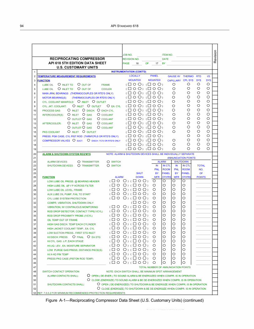
94 API STANDARD 618
Figure A-1—Reciprocating Compressor Data Sheet (U.S. Customary Units) (continued)
JOB NO. ITEM NO.
RECIPROCATING COMPRESSOR REVISION NO. DATE
API 618 5TH EDITION DATA SHEET PAGE 16 OF 17 BY
U.S. CUSTOMARY UNITS1 INSTRUMENTATION (CONT'D)
2 TEMPERATURE MEASUREMENT REQUIREMENTS THERMO RTD I/S
3 FUNCTION CAPILLARY CPL SYS SYS SYS
4 LUBE OIL INLET TO OUT OF FRAME ( ) ( )
5 LUBE OIL INLET TO OUT OF COOLER ( ) ( )
6 MAIN JRNL BEARINGS (THERMOCOUPLES OR RTD'S ONLY) ( ) ( )
7 MOTOR BEARING(S) (THERMOCOUPLES OR RTD'S ONLY) ( ) ( )
8 CYL. COOLANT MANIFOLD: INLET OUTLET ( ) ( )
9 CYL. JKT. COOLANT: INLET OUTLET EA. CYL ( ) ( )
10 PROCESS GAS: INLET DISCH. EACH CYL ( ) ( )
11 INTERCOOLER(S) INLET GAS COOLANT ( ) ( )
12 OUTLET GAS COOLANT ( ) ( )
13 AFTERCOOLER: INLET GAS COOLANT ( ) ( )
14 OUTLET GAS COOLANT ( ) ( )
15 PKG COOLANT INLET OUTLET ( ) ( )
16 PRESS. PGK CASE, CYL PIST ROD (THRM'CPLS OR RTD'S ONLY) ( ) ( )
17 COMPRESSOR VALVES SUCT. DISCH. TC'S OR RTD'S ONLY ( ) ( )
18 ( ) ( )
19 ( ) ( )
20 ALARM & SHUTDOWN SYSTEM REQ'MTS NOTE: ALARM & SHUTDOWN DEVICES SHALL BE INDIVIDUALLY SEPARATE21 ANNUNCIATION POINTS22 ALARM DEVICES: TRANSMITTER SWITCH ALARM SHUTDOWN23 SHUTDOWN DEVICES TRANSMITTER SWITCH IN IN CTL IN IN CTL TOTAL24 PNL ROOM PNL ROOM NO.25 SHUT BY PANEL BY PANEL OF26 FUNCTION ALARM DOWN MFR OTH'RS MFR OTH'RS POINTS
27 LOW LUBE OIL PRESS. @ BEARING HEADER ( ) ( )
28 HIGH LUBE OIL P AP ACROSS FILTER ( ) ( )
29 LOW LUBE OIL LEVEL, FRAME ( ) ( )
30 AUX LUBE OIL PUMP, FAIL TO START ( ) ( )
31 CYL LUBE SYSTEM PROTECTION ( ) ( )
32 COMPR. VIBRATION, SHUTDOWN ONLY ( )
33 VIBRATION, W/ CONTINUOUS MONITORING ( ) ( )
34 ROD DROP DETECTOR, CONTACT TYPE(1/CYL) ( ) ( )
35 ROD DROP PROXIMITY PROBE (1/CYL) ( ) ( )
36 OIL TEMP OUT OF FRAME ( ) ( )
37 HIGH GAS DISCH. TEMP EACH CYLINDER ( ) ( )
38 HIGH JACKET COOLANT TEMP., EA. CYL ( ) ( )
39 LOW SUCTION PRESS., FIRST STG INLET ( ) ( )
40 HI DISCH. PRESS. FINAL EA STG ( ) ( )
41 HI CYL. GAS P, EACH STAGE ( ) ( )
42 HI LIQ. LEV., EA. MOISTURE SEPARATOR ( ) ( )
43 LOW PURGE GAS PRESS, DISTANCE PIECE(S) ( ) ( )
44 HI X-HD PIN TEMP ( ) ( )
45 PRESS PKG CASE (PISTON ROD TEMP) ( ) ( )
46 ( ) ( )
47 TOTAL NUMBER OF ANNUNCIATION POINTS
48 SWITCH CONTACT OPERATION NOTE: EACH SWITCH SHALL BE MINIMUM SPDT ARRANGEMENT
49 ALARM CONTACTS SHALL: OPEN ( DE-ENER.) TO SOUND ALARM & BE ENERGIZED WHEN COMPR. IS IN OPERATION
50 CLOSE (ENERGIZE) TO SOUND ALARM & BE DE-ENERGIZED WHEN COMPR. IS IN OPERATION
51 SHUTDOWN CONTACTS SHALL: OPEN ( DE-ENERGIZED) TO SHUTDOWN & BE ENERGIZE WHEN COMPR. IS IN OPERATION
52 CLOSE (ENERGIZE) TO SHUTDOWN & BE DE-ENERGIZE WHEN COMPR. IS IN OPERATION
53 REF: 7.6.6.2 FOR MINIMUM RECOMMENDED PROTECTION REQUIREMENTS
S 618 16
GAUGE W/
Rev
isio
n
PANEL
MOUNTED
LOCALLY
MOUNTED
--``,,,``,,`````,``,,,,,,,`,,`,,-`-`,,`,,`,`,,`---

RECIPROCATING COMPRESSORS FOR PETROLEUM, CHEMICAL, AND GAS INDUSTRY SERVICES 95
Figure A-1—Reciprocating Compressor Data Sheet (U.S. Customary Units) (continued)
JOB NO. ITEM NO.
RECIPROCATING COMPRESSOR REVISION NO. DATE
API 618 5TH EDITION DATA SHEET PAGE 17 OF 17 BY
U.S. CUSTOMARY UNITS1
2 MISCELLANEOUS INSTRUMENTATION
3 SIGHT FLOW IND. (COOLANT ONLY) ( ) FOR: INTERCOOLER(S) AFTER CLR OIL COOLER
4 CYL JACKET COOLANT ROD PRESS. PKG COOLANT
5 PNEUMATIC PRESSURE TRANSMITTERS ( ) FOR:
6 PRESSURE TRANSMITTERS (ELEC. OUTP.) ( ) FOR:
7 PNEUMATIC LEVEL TRANSMITTERS ( )
8 ALARM HORN & ACKN'LMT TEST BUTTON ( )
9 CONDUIT & WIRING W/JUNCT. BOXES ( )
10 TEST VALVES ( ) FOR:
11 DRAIN VALVES ( ) FOR:
12 GAUGE GLASS(ES) ( ) FOR:
13 TACHOMETER ( ) SPEED RANGE TO r/min
14 CRANKSHAFT KEY PHASER ( ) FOR:
15 AND TRANSDUCER
16 ( )
17 SEPARATE LUBE OIL CONSOLE INSTRUMENTATION: PURCH. TO LIST REQ'MTS IN ADDITION TO ANY ABOVE REQ'MTS
18 ( )
19 ( )
20 ( )
21 ( )
22 ( )
23 ( )
24 SEPARATE COOLING WATER CONSOLE INSTRUMENT: PURCH. TO LIST REQ'MTS IN ADDITION TO ANY ABOVE REQ'MTS
25 ( )
26 ( )
27 ( )
28 ( )
29 ( )
30 ( )
31 RELIEF VALVES
32 LOCATION BY MANUFACTURER TYPE SIZE SETTING
33 ( )
34 ( )
35 ( )
36 ( )
37 ( )
38 ( )
39 ( )
40 ( )
41 ( )
42 ( )
43 NOTES: SEE MOTOR DATA SHEET FOR ADDITIONAL MOTOR INSTRUMENTATION REQUIREMENTS
44 FOR TURBINE DRIVERS USE APPLICABLE API DATA SHEETS
45 FOR GEAR REDUCERS USE APPLICABLE API DATA SHEETS
46 ELECTRICAL & INSTRUMENTATION CONNECTIONS SHALL BE MADE DIRECTLY BY THE PURCHASER TO INDIVIDUAL
47 INSTRUMENTS ON THE COMPRESSOR
48 ADDITIONAL INSTRUMENTATION REMARKS/SPECIAL REQUIREMENTS:
49
50
51
Rev
isio
n
INSTRUMENTATION (CONT'D)
(CON-SOLES)
--``,,,``,,`````,``,,,,,,,`,,`,,-`-`,,`,,`,`,,`---

96 API STANDARD 618
Figure A-2—Reciprocating Compressor Data Sheet (SI Units)
JOB NO. ITEM NO.
PURCHASE ORDER NO.
SPECIFICATION NO.
REVISION NO. DATE
PAGE 1 OF 17 BY
1 APPLICABLE TO: PROPOSALS PURCHASE AS BUILT
2 FOR/USER SITE/LOCATION SERVICE NO. REQ'D
3 NOTE: INDICATES INFO. TO BE BY MANUFACTURER BY MANUFACTURER BY MANUFACTURER OR
4 COMPLETED BY PURCH. WITH PROPOSAL AFTER ORDER PURCHASER AS APPLICABLE
5 COMPR. MFGR TYPE MODEL NO(S) SERIAL NO(S)
6 COMPR.THROWS: TOTAL NO. NO. WITH CYLS. NOMINAL FRAME RATING BkW @ RATED R/MIN OF
7 MAX/MIN ALLOWABLE SPEED / r/min
8 DRIVER MFGR. DRIVER NAMEPLATE HP/OPERATING r/min /
9 DRIVE SYSTEM: DIRECT COUPLED GEARED & COUPLED V-BELT
10 TYPE OF DRIVER: IND. MOTOR SYN. MOTOR STEAM TURBINE GAS TURBINE ENGINE OTHER
11 CYLINDERS CONSTRUCTION: LUBE NON-LUBE
12
13 MAX ACCEPTABLE AVG PISTON SPEED m/s
14 OPERATING CONDITIONS (EACH MACHINE)
15 SERVICE OR ITEM NO.
16 STAGE
17 NORM. OR ALT. CONDITION
18 CERTIFIED PT. (X) MARK ONE
19 MOLECULAR WEIGHT
20 CP/CV (K) @ 65°C OR °C
21 INLET CONDITIONS: AT INLET TO: PULSE DEVICES COMPRESSOR CYLINDER FLANGES
22 NOTE: SIDE STREAM TO STAGE(S), THESE INLET PRESS. ARE FIXED
23 PRESSURE (bar) @ PUL. SUPP. INLET
24 PRESSURE (bar) @ CYL. FLANGE
25 TEMPERATURE (°C)
26 REC: SIDE STREAM TEMPS (°C)
27 COMPRESSIBILITY (Zs )
28 INTERSTAGE: INTERSTAGE P INCL: PULSE DEVICES PIPING COOLERS SEPARATORS OTHER
29 P BETWEEN STAGES, %/bar
30 DISCHARGE CONDITIONS: AT OUTLET FROM: PULSE DEVICE COMP. CYL. FLANGES OTHER
31 PRESSURE (bar) @ CYL. FLANGE
32 PRESS. (bar) @ PUL. SUPP. OUTLET
33 TEMP., ADIABATIC, °C
34 TEMP., PREDICTED, °C
35 COMPRESSIBILITY (Z2 ) OR (ZAVG )
36 * CAPACITY AT INLET TO COMPRESSOR, NO NEGATIVE TOLERANCE (-0%)
37 CAPACITY SPECIFIED
38 IS WET DRY
39 m3/h (1 bar & 60°C)
40 * MFGR.'S RATED CAPACITY (AT INLET TO COMPRESSSOR & kW @ CERTIFIED TOLERANCE OF ±3% FOR CAP. & ±3% FOR kW)
41 CAPACITY SPECIFIED
42 IS WET DRY
43 INLET VOLUME FLOW (m3/h)
44 MMSCCD/SCCM (14.7 PSIA & 60°C)
45 BkW/STAGE
46 TOTAL BkW @ COMPRESSOR SHAFT
47 TOTAL kW INCLUDING
48 V-BELT & GEAR LOSSES
49 * CAPACITY FOR NNT REMARKS:
50 MANUFACTURER'S = REQUIRED ÷ 0.97
51 THEREFORE REQUIRED = MFR'S x 0.97
Rev
isio
n
RECIPROCATING COMPRESSORAPI 618 5TH EDITION DATA SHEET
SI UNITS
kg/h
kg/h
--``,,,``,,`````,``,,,,,,,`,,`,,-`-`,,`,,`,`,,`---

RECIPROCATING COMPRESSORS FOR PETROLEUM, CHEMICAL, AND GAS INDUSTRY SERVICES 97
--``,,,``,,`````,``,,,,,,,`,,`,,-`-`,,`,,`,`,,`---
Figure A-2—Reciprocating Compressor Data Sheet (SI Units) (continued)
JOB NO. ITEM NO.
RECIPROCATING COMPRESSOR REVISION DATE
API 618 5TH EDITION DATA SHEET PAGE 2 OF 17 BY
SI UNITS1 GAS ANALYSIS AT OPERATING CONDITIONS
2 MOLE % (BY VOLUME) ONLY
3 SERVICE/ITEM NO.
4 STAGE
5 NORMAL OR ALT
6 M.W.
7 AIR 28.966
8 OXYGEN O2 32.000
9 NITROGEN N2 28.016
10 WATER VAPOR H2O 18.016
11 CARBON MONOX. CO 28.010
12 CARBON DIOX. CO2 44.010
13 HYDRO. SULFIDE H2S 34.076
14 HYDROGEN H2 2.016
15 METHANE CH4 16.042
16 ETHYLENE C2H4 28.052
17 ETHANE C2H6 30.068
18 PROPYLENE C3H6 42.078
19 PROPANE C3H8 44.094
20 I-BUTANE C4H10 58.120
21 n-BUTANE C4H10 58.120
22 I-PENTANE C5H12 72.146 APPLICABLE SPECIFICATIONS
23 n-PENTANE C5H12 72.146 API 618, RECIPROCATING COMPRESSORS
24 HEXANE PLUS FOR PETROLEUM, CHEMICAL AND GAS
25 AMMONIA NH3 17.031 INDUSTRY SERVICES
26 HYDRO. CHLOR. HCI 36.461 NACE MR-O175 (6.15.1.11)
27 CHLORINE Cl2 70.914
28 CHLORIDES - TRACES
29
30
31
32 CALCULATED MOL WT.
33 Cp/Cv (K) @ 65° OR °C
34 NOTE: IF WATER VAPOR AND/OR CHLORIDES ARE PRESENT, EVEN MINUTE
35 TRACES, IN THE GAS BEING COMPRESSED, IT MUST BE INCLUDED ABOVE.
36 SITE/LOCATION CONDITIONS
37 ELEVATION m bar AMBIENT TEMPS: MAX °C MIN °C
38 MIN DESIGN METAL TEMP °C (6.15.8.1) RELATIVE HUMIDITY: MAX % MIN %
39 COMPRESSOR LOCATION: INDOOR HEATED UNHEATED AT GRADE LEVEL ELEVATED: m
40 OUTDOOR NO ROOF UNDER ROOF PARTIAL SIDES PLATFORM: ON-SHORE
41 OFF-SHORE WEATHER PROTECTION REQ. TROPICALIZATION REQ.
42 WINTERIZATION REQUIRED
43 UNUSUAL CONDITIONS: CORROSIVES DUST FUMES OTHER
44
45 ELECTRICAL CLASSIFICATIONS
46 HAZARDOUS NON-HAZARDOUS
47 MAIN UNIT CLASS GROUP DIVISION
48 L.O. CONSOLE CLASS GROUP DIVISION
49 CW CONSOLE CLASS GROUP DIVISION
50
51
REMARKS
Rev
isio
n

98 API STANDARD 618
Figure A-2—Reciprocating Compressor Data Sheet (SI Units) (continued)
JOB NO. ITEM NO.
RECIPROCATING COMPRESSOR REVISION DATE
API 618 5TH EDITION DATA SHEET PAGE 3 OF 17 BY
SI UNITS1 PART LOAD OPERATING CONDITIONS
2 CAPACITY CONTROL BY: MFG'S CAP. CONTROL PURCHASERS BY-PASS BOTH OTHER
3 FOR: PART LOAD COND. START-UP ONLY BOTH
4 WITH: AUTO LOADING DELAY INTERLOCK (7.6.2.4) AUTO IMMEDIATE UNLOADING
5 USING: FIXED VOLUME POCK. SUCTION VALVE UNLOADERS: FINGER PLUG OTHER
6 ACTION: DIRECT (AIR-TO-UNLOAD) REVERSE (AIR-TO-LOAD/FAIL SAFE)
7 NUMBER OF STEPS: ONE THREE FIVE OTHER
8 RAIN COVER REQUIRED OVER UNLOADERS
9 ALL UNLOADING STEPS BASIS MANUFACTURERS CAPACITY SHOWN ON PAGE 1.
10 INLET AND DISCHARGE PRESSURE ARE AT CYLINDER FLANGES PULSATION SUPPRESSOR FLANGES
11 SERVICE OR ITEM NO.
12 STAGE
13 NORMAL OR ALTERNATE CONDITION
14 PERCENT CAPACITY
15 WEIGHT FLOW, kg/h
16 MMSCFD/SCFM (14.7 bar & 60°C)
17 POCKETS/VALVES OPERATION *
18 POCKET CLEARANCE ADDED %
19 TYPE UNLOADERS, PLUG/FINGER
20 INLET TEMPERATURE, °C
21 INLET PRESSURE, bar
22 DISCHARGE PRESSURE, bar
23 DISCHARGE TEMP., ADIABATIC °C
24 DISCHARGE TEMP., PREDICTED °C
25 VOLUMETRIC EFF.,%HE/%CE
26 CALC. GAS ROD LOAD, kN, C **
27 CALC. GAS ROD LOAD, kN, T **
28 COMB. ROD LOAD, LB C (GAS & INERTIA)
29 COMB. ROD LOAD, LB T (GAS & INERTIA)
30 ROD REV., DEGREES MIN @ X-HD PIN ***
31 kW/STAGE
32 TOTAL kW @ COMPRESSOR SHAFT
33 TOTAL kW INCL. V-BELT & GEAR LOSSES
34
35 * SHOW OPERATION WITH THE FOLLOWING SYMBOLS:
36 SUCTION VALVE(S) UNLOADED = S
37 HEAD END = HE OR
38 OR PLUS FIXED POCKET OPEN = F
39 CRANK END = CE OR
40 VARIABLE POCKET OPEN = V
41
42 EXAMPLE: HE-F/CE-S = HEAD END FIXED POCKET OPEN / CRANK END SUCTION VALVE(S) UNLOADED.
43 * * C = COMPRESSION T = TENSION *** X - HD = CROSSHEAD
44 MINIMUM PRESSURE REQUIRED TO OPERATE CYLINDER UNLOADING DEVICES, barg
45 CYLINDER UNLOADING MEDIUM: AIR NITROGEN OTHER
46 PRESSURE AVAILABLE FOR CYLINDER UNLOADING DEVICES, MAX/MIN / barg
47 REMARKS, SPECIAL REQUIREMENTS, AND/OR SKETCH
48
49
50
51
Rev
isio
n
--``,,,``,,`````,``,,
,,,,,`,,`,,-`-`,,`,,`,`,,`---
RECIPROCATING COMPRESSORS FOR PETROLEUM, CHEMICAL, AND GAS INDUSTRY SERVICES 99
Figure A-2—Reciprocating Compressor Data Sheet (SI Units) (continued)
JOB NO. ITEM NO.
RECIPROCATING COMPRESSOR REVISION DATE
API 618 5TH EDITION DATA SHEET PAGE 4 OF 17 BY
SI UNITS1 SCOPE OF BASIC SUPPLY
2 PURCHASER TO FILL IN ( ) AFTER COMMODITY TO INDICATE: BY COMPR. MFR. BY PURCH. BY OTHERS
3 DRIVER ( ): VARIABLE SPEED SPEED RANGE r/min TO r/min
4 INDUCTION MOTOR SYNCHRONOUS MOTOR STEAM TURBINE ENGINE OTHER
5 API 541 API 546 API 611 API 612
6 OUTBOARD BEARING PROVISION FOR DRY AIR PURGE FOR OUTBOARD BEARING.
7 SLIDE BASE FOR DRIVER ( ) SOLE PLATE FOR DRIVER ( )
8 MOTOR STARTING EQUIPMENT ( ); DEFINE
9 GEAR ( ): BASEPLATE FOR GEAR API 613 API 677
10 COUPLING(S) ( ): LOW SPD. HI-SPD. QUILL SHAFT KEY-LESS DRV. KEY'D DRV. OTHER
11 API 671
12 V-BELT DRIVE ( ): SHEAVES & V-BELTS ( ) STATIC CONDUCTING V-BELTS BANDED V-BELTS
13 DRIVE GUARD(S) ( ): MANUFACTURER'S STD. NON-SPARKING CALIF CODE API 671, ANNEX G
14 OTHER
15 PULSATION SUPPRESSORS ( ): INITIAL INLET & FINAL DISCHARGE SUPPORTS ( )
16 INTERSTAGE SUPPORTS ( )
17 SUPPRESSOR(S) TO HAVE MOISTURE REMOVAL SECTION: INITIAL INLET ALL INTERSTAGE INLET
18 ACOUSTICAL SIMUL. STUDY ( ): DESIGN 1, EMPIRICAL PULSATION SUPRESSION DEVICE SIZING
19 APPROACH 2, ACOUSTIC SIMULATION AND PIPING RESTRAINT ANALYSIS
20 CHECK ONLY ONE, SEE 7.9.4.1.1, TABLE 6) 3, ACOUSTIC SIMULATION AND PIPING RESTRAINT ANALYSIS
21 STUDY TO CONSIDER: PLUS MECHANICAL ANALYSIS
22 ALL SPECIFIED LOAD COND., INCL. SINGLE ACT., PLUS COMP.OPER.IN PARALLEL ALTERNATE GASES
23 CRITICAL FLOW MEASUREMENT (7.9.4.2.5.3.3) WITH EXISTING COMP. AND PIPING SYSTEMS
24 PULSATION SUPRESS'N DEVICE LOW CYCLE FATIGUE ANALYSIS PIPING SYSTEM FLEXIBILITY
25 VENDOR REVIEW OF PURCHASER'S PIPING ARRANGEMENT
26 NOTE: SEE APPENDIX N FOR INFORMATION REQUIRED FOR STUDY
27 PACKAGED: NO YES ( ) DEFINE BASIC SCOPE OF PACKAGING IN REMARKS SECTION, PAGE 5
28 DIRECT GROUTED CEMENTED/MORTAR GROUT EPOXY GROUT; MFG/TYPE /
29 RAILS CHOCK BLOCKS SHIMS BASEPLT. SKID SOLEPLT. BOLTS OR STUDS FOR SOLEPLT. TO FRAME
30 SUITABLE FOR COLUMN MOUNTING (UNDER SKID AND/OR BASEPLATE)
31 LEVELING SCREWS NON-SKID DECKING SUB SOLEPLATES
32 INTERCLR(S) ( ) OFF MOUNTED MACHINE MTD. AFTERCLR(S) ( )
33 SEPARATOR(S) ( ) CONDENSATE SEPARATION & COLLECTION FACILITY SYSTEM (7.8.2.1)
34 INTERSTAGE PIP. ( ): FINAL DISC. PIP. ( ): PARTIAL PRE FAB, FIELD FIT SHOP FITTED
35 FLANGE FINISH API 618 FLANGE FINISH > 125 < 250 (7.9.5.1.16) FLANGE FINISH PER ANSI 16.5 SPECIAL FINISH
36 SPECIAL PIPING REQUIREMENTS (7.7.1.13). (DEFINE IN REMARKS SECTION NEXT PAGE)
37 INITIAL INLET, INTERSTAGE SUCTION PIPING ARR'D FOR: INSULATION ( ) HEAT TRACING (
38 INLET STRAINER(S) ( ): INITIAL INLET SIDESTREAM INLET SPOOL PIECE FOR INLET STRAINERS
39 MANIFOLD PIPING; DRAINS VENTS RELIEF VALVES AIR/GAS SUPPLY
40 RELIEF VALVE(S) ( ): INITIAL INLET INTERSTAGE FINAL DISCHARGE
41 RUPTURE DISC(S) ( ) THRU STUDS IN PIPING FLANGES
42 FOR ATMOSPHERIC INLET AIR COMPR. ONLY: INLET AIR FILTER ( ) INLET FILTER -SILENCER ( )
43 PREFERRED TYPE OF CYLINDER COOLING ( ): FORCED THERMOSYPHON STAGE CYL'(S)
44 NOTE: MANUFACTURER SHALL RECOMMEND STATIC (STAND-PIPE) STAGE CYL'(S)
45 BEST TYPE OF COOLING AFTER CYL. COOLANT PIPING BY ( ) MATCH M'RKED
46 FINAL ENGINEERING REVIEW OF ALL SINGLE INLET/OUTLET MANIFOLD & VALVES SIGHT GL'SS(ES)
47 OPERATING CONDITIONS INDIVIDUAL INLET/ OUTLET PER CYL. VALVE(S)
48 CLOSED SYSTEM WITH PUMP, COOLER, SURGE TANK, & PIPING
49
50
51
Rev
isio
n
--``,,,``,,`````,``,,,,,,,`,,`,,-`-`,,`,,`,`,,`---

100 API STANDARD 618
--``,,,``,,`````,``,,,,,,,`,,`,,-`-`,,`,,`,`,,`---
Figure A-2—Reciprocating Compressor Data Sheet (SI Units) (continued)
JOB NO. ITEM NO.
REVISION DATE
PAGE 5 OF 17 BY
1 SCOPE OF BASIC SUPPLY (Con't)
2 SEPARATE COOLING CONSOLE ( ): ONE FOR EA. UNIT ONE CMMN TO ALL UNITS DUAL PUMPS (AUX .& MAIN)
3 ARRANGED FOR HEATING JACKET WATER AS WELL AS COOLING SHOP RUN
4 ROD PRESS. PACKING COOLING SYSTEM ( ): SEPARATE CONSOLE COMBINE WITH JKT SYSTEM FILTERS
5 FRAME LUBE OIL SYSTEM ( ): AUX. PUMP DUAL FILTERS WITH TRANSFER VALVE SHOP RUN
6 CONTINUOUS FLOW IN SENSING LINE TO PRESSURE SWITCHES
7 SEPARATE LUBE OIL CONSOLE ( ): EXTENDED TO MOTOR OUTBOARD BEARING SHOP RUN
8 NOTE: PIPING BETWEEN ALL CONSOLES AND COMPRESSOR UNIT BY PURCHASER
9 CAPACITY CONTROL ( ): SEE DATA SHEET PAGE 3 FOR DETAILS IN INSTRUMENT & CONTROL PANEL
10 SEPARATE MACHINE MOUNTED PANEL SEPARATE FREE STANDING PANEL
11 PNEUMATIC ELECTRIC ELECTRONIC HYDRAULIC
12 PROGRAMMABLE CONTROLLER
13 INSTRUMENT & CONTROL PANEL ( ): ONE FOR EACH UNIT ONE COMMON TO ALL UNITS
14 MACHINE MOUNTED FREE STANDING (OFF UNIT)
15 BUFFER GAS CONTROL PANEL ( ): ONE FOR EACH UNIT ONE COMMON TO ALL UNITS
16 MACHINE MOUNTED FREE STANDING (OFF UNIT)
17 SEE INSTRUMENTATION DATA SHEETS FOR DETAILS OF PANEL, ADDITIONAL REMARKS, AND INSTRUMENTATION.
18 NOTE: ALL TUBING, WIRING, & CONNECTIONS BETWEEN OFF-UNIT FREE STANDING PANELS AND COMPRESSOR UNIT BY
19 PURCHASER.
20
21 HEATERS ( ): FRAME LUBE OIL CYL. LUBRICATORS COOLING WATER DRIVER(S) GEAR OIL
22 ELECTRIC STEAM
23
24 BARRING DEVICE ( ): MANUAL PNEUMATIC ELECTRIC FLYWHEEL LOCKING DEVICE ( )
25 CRANKCASE RAPID PRESSURE RELIEF DEVICE(S) ( )
26 SPECIAL CORROSION PROTECTION: NO YES MFR'S STANDARD OTHER
27 HYDRAULIC TENSIONING TOOLS NO YES
28 MECHANICAL RUN TEST: NO YES MFG'S STANDARD OTHER
29 COMPLETE SHOP RUN TEST OF ALL MACHINE MOUNTED EQUIPMENT, PIPING & APPURT.'(S)
30
31 PAINTING: MANUFACTURER'S STANDARD SPECIAL
32 NAMEPLATES: U.S. CUSTOMARY UNITS SI UNITS
33 SHIPMENT: DOMESTIC EXPORT EXPORT BOXING REQUIRED ( )
34 STANDARD 6 MONTH STORAGE PREPARATION ( ), PER SPEC
35 OUTDOOR STORAGE FOR OVER 6 MONTHS ( ), PER SPEC
36 INITIAL INSTALLATION AND OPERATING TEMP ALIGNMENT CHECK AT JOBSITE BY VENDOR REPRESENTATIVE
37 COMPRESSOR MANUFACTURER'S USER'S LIST FOR SIMILAR SERVICE
38 COMPRESSOR VALVE DYNAMIC RESPONSE
39 PERFORMANCE DATA REQUIRED (9.3.3): BHP VS. SUCTION PRESSURE CURVES
40 ROD LOAD/GAS LOAD CHARTS
41 VALVE FAILURE DATA CHARTED
42 SPEED/TORQUE CURVE DATA
43 BkW VS. CAPACITY PERFORMANCE CURVES OR TABLES REQUIRED FOR UNLOADING STEPS AND/OR VARIABLE
44 SUCTION/DISCHARGE PRESSURES
45
46 REMARKS:
47
48
49
50
51
SI UNITSAPI 618 5TH EDITION DATA SHEETRECIPROCATING COMPRESSOR
Rev
isio
n
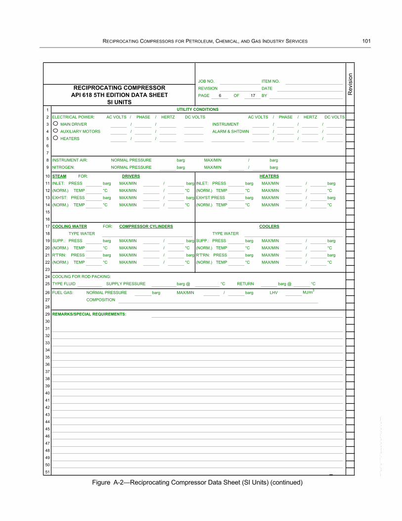
RECIPROCATING COMPRESSORS FOR PETROLEUM, CHEMICAL, AND GAS INDUSTRY SERVICES 101
--``,,,``,,`````,``,,,,,,,`,,`,,-`-`,,`,,`,`,,`---
Figure A-2—Reciprocating Compressor Data Sheet (SI Units) (continued)
JOB NO. ITEM NO.
RECIPROCATING COMPRESSOR REVISION DATE
API 618 5TH EDITION DATA SHEET PAGE 6 OF 17 BY
SI UNITS1 UTILITY CONDITIONS
2 ELECTRICAL POWER: AC VOLTS / PHASE / HERTZ DC VOLTS AC VOLTS / PHASE / HERTZ DC VOLTS
3 MAIN DRIVER / / INSTRUMENT / / /
4 AUXILIARY MOTORS / / ALARM & SHTDWN / / /
5 HEATERS / / / / /
6
7
8 INSTRUMENT AIR: NORMAL PRESSURE barg MAX/MIN / barg
9 NITROGEN: NORMAL PRESSURE barg MAX/MIN / barg
10 STEAM FOR: DRIVERS HEATERS
11 INLET: PRESS barg MAX/MIN / barg INLET: PRESS barg MAX/MIN / barg
12 (NORM.) TEMP °C MAX/MIN / °C (NORM.) TEMP °C MAX/MIN / °C
13 EXH'ST: PRESS barg MAX/MIN / barg EXH'ST:PRESS barg MAX/MIN / barg
14 (NORM.) TEMP °C MAX/MIN / °C (NORM.) TEMP °C MAX/MIN / °C
15
16
17 COOLING WATER FOR: COMPRESSOR CYLINDERS COOLERS
18 TYPE WATER TYPE WATER
19 SUPP.: PRESS barg MAX/MIN / barg SUPP.: PRESS barg MAX/MIN / barg
20 (NORM.) TEMP °C MAX/MIN / °C (NORM.) TEMP °C MAX/MIN / °C
21 R'T'RN: PRESS barg MAX/MIN / barg R'T'RN: PRESS barg MAX/MIN / barg
22 (NORM.) TEMP °C MAX/MIN / °C (NORM.) TEMP °C MAX/MIN / °C
23
24 COOLING FOR ROD PACKING:
25 TYPE FLUID SUPPLY PRESSURE barg @ °C RETURN barg @ °C
26 FUEL GAS: NORMAL PRESSURE barg MAX/MIN / barg LHV MJ/m3
27 COMPOSITION
28
29 REMARKS/SPECIAL REQUIREMENTS:
30
31
32
33
34
35
36
37
38
39
40
41
42
43
44
45
46
47
48
49
50
51
Rev
isio
n

102 API STANDARD 618
Figure A-2—Reciprocating Compressor Data Sheet (SI Units) (continued)
JOB NO. ITEM NO.
RECIPROCATING COMPRESSOR REVISION DATE
API 618 5TH EDITION DATA SHEET PAGE 7 OF 17 BY
SI UNITS1 CYLINDER DATA AT FULL LOAD CONDITION
2 SERVICE/ITEM NO.
3 STAGE
4 INLET PRESSURE, barg @ CYLINDER
5 DISCHARGE PRESSURE, barg FLANGES
6 CYLINDERS PER STAGE
7 SINGLE OR DOUBLE ACTING (SA OR DA)
8 BORE, mm
9 STROKE, mm
10 RPM: RATED / MAX ALLOW
11 PISTON SPEED, m/s: RATED / MAX ALLOW
12 CYLINDER LINER, YES/NO
13 LINER NOMINAL THICKNESS, mm
14 PISTON DISPLACEMENT, m3/h
15 CYLINDER DESIGN CLEARANCE, % AVERAGE
16 VOLUMETRIC EFFICIENCY, % AVERAGE
17 VALVES, INLET/DISCHARGE, QTY PER CYL.
18 TYPE OF VALVES
19 VALVE LIFT, INLET/DISCHARGE, mm
20 VALVE VELOCITY, m/s
21 SUCTION VALVE(S)
22 DISCHARGE VALVE(S)
23 ROD DIAMETER, mm
24 MAX ALLOW. COMBINED ROD LOADING, kN, C *
25 MAX ALLOW. COMBINED ROD LOADING, kN, T *
26 CALCULATED GAS ROD LOAD, kN, C *
27 CALCULATED GAS ROD LOAD, kN, T *
28 COMBINED ROD LOAD (GAS + INERTIA), kN, C *
29 COMBINED ROD LOAD (GAS + INERTIA), kN, T *
30 ROD REV., DEGREES MIN @ X-HD PIN**
31 RECIP WT. (PISTON, ROD, X-HD & NUTS), kg**
32 MAX ALLOW. WORKING PRESSURE, barg
33 MAX ALLOW. WORKING TEMPERATURE, °C
34 HYDROSTATIC TEST PRESSURE, barg
35 GAS LEAKAGE TEST PRESSURE, barg
36 INLET FLANGE SIZE/RATING
37 FACING
38 DISCHARGE FLANGE SIZE/RATING
39 FACING
40 DISCHARGE RELIEF VALVE SETTING DATA AT INLET PRESSURES GIVEN ABOVE:
41 RECOMMENDED SETTING, barg
42 GAS ROD LOAD, kN, C *
43 GAS ROD LOAD, kN, T *
44 COMBINED ROD LOAD, kN, C *
45 COMBINED ROD LOAD, kN, T *
46 ROD REVERSAL, °MIN @ X-HD PIN**
47 NOTE: CALCULATED AT INLET PRESSURES
48 GIVEN ABOVE & RECOMMENDED SETTING.
49 SETTLE-OUT GAS PRESSURE
50 (DATA REQUIRED FOR STARTING) * C = COMPRESSION * T = TENSION **X-HD = CROSSHEAD
51 NOTES/REMARKS:
Rev
isio
n
}
--``,,,``,,`````,``,,,,,,,`,,`,,-`-`,,`,,`,`,,`---

RECIPROCATING COMPRESSORS FOR PETROLEUM, CHEMICAL, AND GAS INDUSTRY SERVICES 103
Figure A-2—Reciprocating Compressor Data Sheet (SI Units) (continued)
JOB NO. ITEM NO.
RECIPROCATING COMPRESSOR REVISION DATE
(API 618-5TH) DATA SHEET PAGE 8 OF 17 BY
SI UNITS1
2 SERVICE ITEM NO.
3 STAGE
4 CYLINDER SIZE (BORE DIA), mm
5 ROD RUN-OUT: NORMAL COLD VERTICAL
6 (per Annex C)
7 CYLINDER INDICATOR VALVES REQUIRED
8 INDICATOR CONNECTIONS ABOVE 345 bar
9 FLUOROCARBON SPRAYED CYLINDER
10 CYLINDER(S)
11 CYLINDER LINER(S)
12 PISTON(S)
13 PISTON RINGS
14 WEAR BANDS REQUIRED
15 PISTON ROD(S): MATERIAL/YIELD, N/mm2
16 THREAD ROOT STRESS @ MACRL * @ X-HD END
17 PISTON ROD HARDNESS, BASE MATERIAL, Rc
18 PISTON ROD COATING X REQUIRED
19 COATING HARDNESS, Rc
20 VALVE SEATS / SEAT PLATE
21 VALVE SEAT MIN HARDNESS, Rc
22 VALVE GUARDS (STOPS)
23 VALVE DISCS
24 VALVE SPRINGS
25 ROD PRESSURE PACKING RINGS
26 ROD PRESSURE PACKING CASE
27 ROD PRESSURE PACKING SPRINGS
28 SEAL / BUFFER PACKING, DISTANCE PIECE
29 SEAL / BUFFER PACKING, INTERMEDIATE
30 WIPER PACKING RINGS
31 MAIN JOURNAL BEARINGS, CRANKSHAFT
32 CONNECTING ROD BEARING, CRANKPIN
33 CONNECTING ROD BUSHING, X-HD END
34 CROSSHEAD (X-HD) PIN BUSHING
35 CROSSHEAD PIN
36 CROSSHEAD
37 CROSSHEAD SHOES
38 INSTRUMENTATION IN COLD SIDE
39 CONTACT W/PROCESS GAS HOT SIDE
40 * MACRL = MAXIMUM ALLOWABLE COMBINED ROD LOAD
41 COMPRESSOR CYLINDER ROD PACKING DISTANCE PIECE(S): TYPE A TYPE B TYPE C TYPE D
42 FULL FLOATING PACKING REF. FIGURE G-3
43 VENTED TO: FLARE @ barg ATMOS. COVERS: SOLID METAL SCREEN LOUVERED
44 SUCTION PRESSURE @ barg CYLINDER COMPARTMENT: VENTED TO barg
45 FORCED LUBRICATED NON-LUBE (Outboard Distance Piece) PURGED AT barg
46 WATER COOLED, STAGE(S), GPM REQ'D PRESSURIZED TO barg
47 OIL COOLED, STAGE(S), GPM REQ'D WITH RELIEF VALVE
48 WATER FILTER PROV.FUTURE WATER/OIL COOLING FRAME COMPARTMENT: VENTED TO barg
49 VENT/BUFFER GAS SEAL PACKING ARR. (REF. FIG I-1) (Inboard Distance Piece) PURGED AT barg
50 CONSTANT OR VARIABLE DISPOSAL SYSTEM PRESSURIZED TO barg
51 BUFFER GAS PRESSURE, barg WITH RELIEF VALVE
52 SPLASH GUARDS FOR WIPER PACKING DISTANCE PIECE MAWP barg
MATERIALS OF CONSTRUCTION
CONSTRUCTION FEATURES
Rev
isio
n--``,,,``,,`````,``,,,,,,
,`,,`,,-`-`,,`,,`,`,,`---
104 API STANDARD 618
Figure A-2—Reciprocating Compressor Data Sheet (SI Units) (continued)
JOB NO. ITEM NO.
RECIPROCATING COMPRESSOR REVISION NO. DATE
(API 618-5TH) DATA SHEET PAGE 9 OF 17 BY
SI UNITS
1
2 FABRICATED CYLINDER, HEADS, & CONNECTION BUFFER GAS PACKING ARR. REF: ANNEX I
3 SKETCHES FOR DESIGN REVIEW OIL WIPER PACKING PURGE FIGURES I-1, I-2 & I-3
4 BY PURCHASER. (6.15.5.13) INTERMEDIATE PARTITION PURGE
5 INERT BUFFER PURGE GAS: N2 OTHER
6 VENT, DRAIN, PURGE PIPING BY MFG'R NO YES
7 COUPLING(S) LOW-SPEED HI-SPEED V-BELT DRIVE DRIVEN SHEAVE DRIVE SHEAVE
8 Between Compressor Between Driver & (COMPRESSOR SHAFT) (DRIVER SHAFT)
9 & Driver or Gear Gear RPM (EXPECTED)
10 BY MANUFACTURER PITCH DIA. (IN.)
11 MODEL QTY & GROOVE X-SEC.
12 TYPE POWER TRANSMITT'D
13 Incl. Belt Losses
14 API-671 APPLIES YES NO DRIVER NAMEPLATE HP RATING
15 INSPECTION AND SHOP TESTS (REF. 8.1.5) CENTER DISTANCE (IN.)
16 REQ'D WITN. OBSER. QTY, TYPE,17 *SHOP INSPECTION X-SEC., & LENGTH BELTS18 ACTUAL RUNNING CLEARANCES BELT SERVICE FACTOR (RELATIVE TO19 AND RECORDS DRIVER NAMEPLATE HP RATING)20 MFG STANDARD SHOP TESTS CYLINDER LUBRICATION21 CYLINDER HYDROSTATIC TEST NON-LUBE STAGE(S)/SERVICE22 CYLINDER PNEUMATIC TEST LUBRICATED STAGE(S)/SERVICE23 CYLINDER HELIUM LEAK TEST TYPE OF LUBE OIL: SYNTHETIC24 CYL. JACKET WATER HYDRO TEST HYDROCARBON25 *MECHANICAL RUN TEST (4 HOUR) LUBRICATOR COMP. CRANKSHAFT, DIRECT26 BAR-OVER TO CHECK ROD RUNOUT DRIVE BY: CHAIN, FROM CRANKSHAFT27 *LUBE OIL CONSOLE RUN/TEST (4 HOUR) ELECTRIC MOTOR28 *COOLING H2O CONSOLE RUN/TEST OTHER
29 RADIOGRAPHY BUTT WELDS LUBRICATOR MFR30 GAS OIL FAB CYLS. MODEL31 MAG PARTICLE/LIQUID TYPE LUBRICATOR: SINGLE PLUNGER PER POINT32 PENETRANT OF WELDS (6.14.3) DIVIDER BLOCKS33 SPECIFY ADDITIONAL COMPARTM'T, TOTAL QTY.34 REQUIREMENTS (8.2.1.3) PLUNGERS (PUMPS), TOTAL QTY.35 SPARE PLUNGERS, QTY.36 SHOP FIT-UP OF PULSATION SUPPL. SPARE COMPARTM'T W/OUT PLUNGERS37 DEVICES & ALL ASSOCIATED HEATERS: ELECTRIC W/THERM.(S) STEAM38 GAS PIPING ESTIMATED WEIGHTS AND NOMINAL DIMENSIONS39 *CLEANLINESS OF EQUIP., PIPING, TOTAL COMPR. WT, LESS DRIVER & GEAR kg40 & APPURTENANCES WT, OF COMPLETE UNIT, (LESS CONSOLES) kg41 *HARDNESS OF PARTS, WELDS & MAXIMUM ERECTION WEIGHT kg42 HEAT AFFECTED ZONES MAXIMUM MAINTENANCE WEIGHT kg43 *NOTIFICATION TO PURCHASER OF DRIVER WEIGHT/GEAR WEIGHT / kg44 ANY REPAIRS TO MAJOR LUBE OIL/COOLANT CONSOLE / kg45 COMPONENTS FREE STANDING PANEL46 SPACE REQUIREMENTS, m: LENGTH WIDTH HEIGHT47 COMPLETE UNIT48 *SPECIFIC REQUIREMENTS TO BE DEFINED, LUBE OIL CONSOLE49 FOR EXAMPLE, DISMANTLING, AUX EQUIPMENT CYLINDER COOLANT CONSOLE
50 OPERATIONAL & RUN TESTS. FREE STANDING PANEL51 ANNEX K COMPLIANCE: VENDOR PISTON ROD REMOVAL DIST.52 PURCHASER OTHER EQUIPMENT SHIPPED LOOSE (DEFINE)53 PULSATION SUPP., WEIGHT kg54 PIPING kg55 INTERSTAGE EQUIPMENT kg
CONSTRUCTION FEATURES (CONTINUED)
Rev
isio
n--``,,,``,,`````,``,,,,,,,`,,`,,-`-`,,`,,`,`,,`---

RECIPROCATING COMPRESSORS FOR PETROLEUM, CHEMICAL, AND GAS INDUSTRY SERVICES 105
Figure A-2—Reciprocating Compressor Data Sheet (SI Units) (continued)
JOB NO. ITEM NO.
RECIPROCATING COMPRESSOR REVISION NO. DATE
API 618 5TH EDITION DATA SHEET PAGE 10 OF 17 BY
SI UNITS1 UTILITY CONSUMPTION
2
3
4
5 FOR INDUCTION NAMEPLATE LOCKED ROTOR FULL LOAD MAIN DRIVER NON-STEADY
6 MOTORS SEE NOTE kW AMPS STEADY STATE STATE AMPS AT COMPRES-
7 OF 7.1.2.6 AND AMPS SOR RATED HORSEPOWER
8 MOTOR DATA SHEET (INDUCTION MOTORS ONLY)
9 MAIN DRIVER AMPS
10 MAIN LUBE OIL PUMP @ COMPRESSOR RATED
11 AUX LUBE OIL PUMP kW OF
12 MAIN CYLINDER COOLANT PUMP @ CURRENT PULSATIONS
13 AUX CYLINDER COOLANT PUMP OF %
14 MAIN ROD PKG COOLANT PUMP
15 AUX ROD PKG COOLANT PUMP
16 CYLINDER LUBRICATOR
17
18
19
20
21 WATTS VOLTS HERTZ
22 FRAME OIL HEATER(S)
23 CYLINDER COOLANT HEATER(S)
24 CYL. LUBRICATOR HEATER(S)
25 MAIN DRIVER SPACE HEATER(S)
26
27
28
29
30 FLOW PRESSURE TEMPERATURE BACK PRESSURE
31 MAIN DRIVER kg/h @ barg °CTT TO barg
32 FRAME OIL HEATER(S) kg/h @ barg °CTT TO barg
33 CYL. LUB. HEATER(S) kg/h @ barg °CTT TO barg
34 kg/h @ barg °CTT TO barg
35 kg/h @ barg °CTT TO barg
36
37
38 FLOW INLET TEMP OUTLET TEMP INLET PRESS OUTLET PRESS MAX PRESS
39 m3/h °C °C barg barg barg
40 CYLINDER JACKETS
41 CYLINDER COOLANT CONSOLE
42 FRAME LUBE OIL COOLER
43 ROD PRESSURE PACKING*
44 PACKING COOLANT CONSOLE
45 INTERCOOLER(S)
46 AFTERCOOLER
47
48 TOTAL QUANTITY, m3/h
49 REMARKS/SPECIAL REQUIREMENTS:
50 *ROD PACKING COOLANT MAY BE OTHER THAN WATER
51
DS 618 10
COOLING WATER REQUIREMENTS
ELECTRIC MOTORS
ELECTRIC HEATERS
STEAM
Rev
isio
n--``,,,``,,`````,``,,,,,,,`,,`,,-`-`,,`,,`,`,,`---

106 API STANDARD 618
Figure A-2—Reciprocating Compressor Data Sheet (SI Units) (continued)
JOB NO. ITEM NO.
RECIPROCATING COMPRESSOR REVISION NO. DATE
API 618 5TH EDITION DATA SHEET PAGE 11 OF 17 BY
SI UNITS1
2 BASIC LUBE OIL SYSTEM FOR FRAME: SPLASH PRESSURE (FORCED) HEATERS REQUIRED:
3 REF: TYPE MAIN BEARINGS: TAP'RD ROLL'R PRECISION SL'VE ELEC. W/THERMOSTAT(S) STEAM
4 PRESSURE SYSTEM: MAIN OIL PUMP DRIVEN BY: COMP. CRANKSHAFT ELEC. MOTOR OTHER
5 PSV FOR MAIN PUMP EXTERNAL TO CRANKCASE CHECK VALVE ON MAIN PUMP (FIG G-5)
6 AUX OIL PUMP DRIVEN BY: ELEC. MOTOR OTHER
7 HAND OPERATED PRE-LUBE PUMP FOR STARTING OPERATIONAL TEST & 4 HOUR MECH RUN TEST
8 CONTINUOUS OIL FLOW THROUGH SWITCH SENSING LINE (7.7.2.5)
9 SEP. CONSOLE FOR PRESS. LUBE SYS: ONE CONSOLE FOR EA. COMP. ONE CONSOLE FOR COMPRESSORS
10 Note: Instrumentation to be listed on CONSOLE TO BE OF DECK PLATE TYPE CONSTRUCTION SUITABLE FOR
11 Instrumentation Data Sheets. MULTI-POINT SUPPORT AND GROUTING WITH GROUT & VENT HOLES.
12 ELECTRICAL CLASSIFICATION : CLASS , GROUP , DIV NON-HAZARDOUS
13 BASIC SYS. REQ'MTS (NORM. OIL FLOWS & VOLUMES)
14 LUBE OIL FLOW PRESSURE VISCOSITY SUMP VOLUME
15 m3/h barg SSU @ 40°C SSU @ 100°C m3
16 COMPRESSOR FRAME
17 DRIVER
18 GEAR
19 SYSTEM PRESSURES: DESIGN barg HYDROTEST barg
20 PRESSURE CONTROL VALVE SETTING barg PUMP REL'F VALVE(S) SET barg
21 PIPING MATERIALS: CARBON STAINLESS STEEL STAINLESS STEEL
22 STEEL WITH SS FLANGES WITH CARBON STEEL FLANGES
23 UPSTREAM OF PUMPS & FILTERS
24 DOWNSTREAM OF FILTERS
25
26
27 PUMPS (Gear RAT'D FL'W PRESSURE COLD START DRIVER SPEED COUPLING MECH. SEAL
28 or Screw Type Only) m3 barg REQ'D kW kW R/MIN REQ'D REQ'D
29 MAIN
30 AUXILIARY
31 PUMP CASING MATERIAL (Ref. 6.14.2.1.5): MAIN PUMP AUX PUMP
32 GUARD(S) REQ. FOR COUPLING(S): MAIN PUMP AUX PUMP GUARD TYPE OR CODE
33 AUXILIARY PUMP CONTROL: MANUAL AUTOMATIC ON-OFF-AUTO SEL. SWITCH: BY PURCH. BY MFR.
34 WIRING TO TERMINAL BOX: BY PURCH. BY MFR.
35 SWITCHES RTD'S/THERMOCOUPLES
36 COOLERS: SHELL & TUBE SINGLE DUAL W/TRANSFER VALVE MFG'S STD. TEMA C TEMA R (API 660)
37 REMOVABLE BUNDLE WATER COOLED AIR COOLED W/AUTO TEMP CONTROL (API-661) Data Shts - Attached
38 W/BYPASS & TEMP CONTROL VALVE: MANUAL AUTO
39 SEE SEPARATE HEAT EXCHANGER DATA SHEETS FOR DETAILS, SPECIFY % GLYCOL ON COOLING WATER SIDE
40 FILTER(S) SINGLE DUAL W/TRANSFER VALVE ASME CODE DESIGN ASME CODE STAMPED
41 DESIGN PRESSURE, barg P CLEAN, barg P COLLAPSE, barg
42 MICRON RATING, CARTRIDGE MATERIAL, CARTRIDGE P/N
43 BONNET MATERIAL, CASING MATERIAL, FURN.SPARE CARTR.,QTY
44 SYS. COMPONENT SUPP. MANUFACTURER MODEL MANUFACTURER MODEL
45 MAIN PUMP OIL COOLER(S)
46 AUXILIARY PUMP TRANSFER VALVE(S)
47 MECHANICAL SEALS PUMP COUPLING(S)
48 ELECTRIC MOTORS SUCTION STRAINER(S)
49 STEAM TURBINES CHECK VALVE(S)
50 OIL FILTER(S)
51
FRAME LUBE OIL SYSTEM
Rev
isio
n
--``,,,``,,`````,``,,,,,,,`,,`,,-`-`,,`,,`,`,,`---

RECIPROCATING COMPRESSORS FOR PETROLEUM, CHEMICAL, AND GAS INDUSTRY SERVICES 107
Figure A-2—Reciprocating Compressor Data Sheet (SI Units) (continued)
JOB NO. ITEM NO.
RECIPROCATING COMPRESSOR REVISION NO. DATE
API 618 5TH EDITION DATA SHEET PAGE 12 OF 17 BY
SI UNITS1
2 BASIC COOLING SYS. FOR: COMPRESSOR CYL.(S) ROD PACKING(S) PROCESS COOLER(S) OIL COOLER(S)
3 HEATERS REQ.'D FOR PRE-HEATING: ELEC.,W/ THERMOSTAT(S) STEAM
4 PRESSURE FORCED CIRCULATING SYS: OPEN, PIPING BY: PURCH. MFR CLOSED, PIPING BY MFR.
5 MAIN COOLANT PUMP DRIVEN BY: ELEC. MOTOR STEAM TURBINE OTHER
6 AUX COOLANT PUMP DRIVEN BY: ELEC. MOTOR STEAM TURBINE OTHER
7 SEP. CONSOLE FOR COOLANT SYSTEM.: ONE CONSOLE FOR EA. COMP. ONE CONSOLE FOR COMP'RS
8 NOTE: CONSOLE TO BE OF DECK PLATE TYPE CONSTRUCTION SUITABLE FOR
9 MULTI-POINT SUPPORT AND GROUTING WITH GROUT & VENT HOLES.
10 ELECTRICAL CLASSIFICATION : CLASS , GROUP , DIV NON-HAZARDOUS
11 BASIC SYS. REQ'MTS (NORM. COOLANT FLOW DATA) COOLANT TO BE % ETHYLENE GLYCOL SITE
12 FORCED THERMO STAND FLOW PRESSURE INLET TEMP OUTLET TEMP FLOW
13 COOL'G SYPHON PIPE m3/h barg °C °C IND'TR
14 CYLINDER(S), STAGE
15 CYLINDER(S), STAGE
16 CYLINDER(S), STAGE
17 CYLINDER(S), STAGE
18 CYLINDER(S), STAGE
19 CYLINDER(S), STAGE
20 PISTON ROD PACK'G TOTAL
21 INTERCOOLER(S) TOTAL
22 AFTERCOOLER
23 OIL COOLER(S)
24
25 TOTAL FLOW
26 SYS. PRESSURES: DESIGN, barg HYDROTEST, barg RELIEF VALVE(S), SETTING barg
27 COOLANT RESERVOIR: SIZE, mm IN DIA X mm IN HT. CAPACITY m3
28 @ NORMAL OPERATING LEVEL
29 RESERVOIR MATERIAL INTERNAL COATING, TYPE
30 LEVEL GAUGE LEVEL SWITCH DRAIN VALVE INSPECTION & CLEAN-OUT OPENINGS
31 PUMPS: (CENTRIFUGAL ONLY) RAT'D FL'W PRESS. REQ'D DRIVER SPEED COUPLING MECH.SEAL
32 m3/h barg kW kW r/min REQ'D REQ'D
33 MAIN
34 AUXILIARY
35 PUMP CASING MATERIAL (Ref 6.14.2.1.5): MAIN PUMP AUX PUMP
36 GUARD(S) REQ.'D FOR COUP'G(S) MAIN PUMP AUX PUMP GUARD TYPE OR CODE
37 AUX.PUMP CONTROL: MANUAL AUTO ON-OFF-AUTO SEL. SWITCH: BY PURCH. BY MANUFACTURER
38 WIRING TO TERMINAL BOX: BY PURCH. BY MANUFACTURER
39 COOLANT HEAT EXCHANGER: SHELL & TUBE SINGLE DUAL W/TRANSFER VALVE TEMA C TEMA R (API 660)40 (DATA SHEETS ATTACHED)
41 AIR COOLED EXCHANGER W/AUTO TEMP CONTROL (API 661 DATA SHEETS ATTACHED)
42 W/BYPASS & TEM. CONTROL VALVE MANUAL AUTO LOUVERS FOR AIR EXCH.
43 SEE SEPARATE COOLER DATA SHEET FOR DETAILS; SPECIFY % GLYCOL ON BOTH SIDES
44 OF SHELL & TUBE
45 SYS. COMPONENT SUPP. MANUFACTURER MODEL MANUFACTURER MODEL
46 MAIN PUMP TEMP CONTROL VALVE(S)
47 AUXILIARY PUMP TRANSFER VALVE(S)
48 MECHANICAL SEALS PUMP COUPLING(S)
49 ELECTRIC MOTORS
50 STEAM TURBINES
51
52
Rev
isio
n
COOLANT SYSTEM
Instrumentation to be listed on instrumentation data sheets.
--``,,,``,,`````,``,,,,,,,`,,`,,-`-`,,`,,`,`,,`---

108 API STANDARD 618
Figure A-2—Reciprocating Compressor Data Sheet (SI Units) (continued)
JOB NO. ITEM NO.
RECIPROCATING COMPRESSOR REVISION NO. DATE
API 618 5TH EDITION DATA SHEET PAGE 13 OF 17 BY
SI UNITS1 PULSATION SUPPRESSION DEVICES FOR RECIPROCATING COMPRESSORS
2 THESE SHEETS TO BE FILLED OUT FOR EACH SERVICE AND/OR STAGE OF COMPRESSION
3 APPLICABLE TO: PROPOSALS PURCHASE AS BUILT
4 FOR/USER
5 SITE/LOCATION AMBIENT TEMPERATURE MIN/MAX / °C
6 COMPRESSOR SERVICE NUMBER OF COMPRESSORS
7 COMPRESSOR MFG. MODEL/TYPE
8 SUPPRESSOR MFG.
9 NOTE: Ind.Data Comp.'d Purch. By Compr/Supp.Mfg.w/Proposal By Mfg(s) after order By Mfg(s)/Purchaser as Applicable
10 GENERAL INFORMATION APPLICABLE TO ALL SUPPRESSORS
11 TOTAL NUMBER OF SERVICES AND/OR STAGES
12 TOTAL NUMBER OF COMPRESSOR CYL. TOTAL NUMBER OF CRANKTHROWS STROKE mm r/min
13 ASME CODE STAMP GOVERNMENTAL CODES OF CODE REGULATIONS APPLY
14 OTHER APPLICABLE PRESSURE VESSEL SPEC. OR CODE
15 LUBE SERVICE NON-LUBE SERV. NO OIL ALLOWED INTERNALLY DRY TYPE INTER.CORR.COATING YES NO
16 RADIOGRAPHY (X-RAY OF WELDS): NONE SPOT 100% IMPACT TEST SPECIAL WELDING REQUIREMENTS
17 SHOP INSPECTION WITNESS HYDROTEST OUTDOOR STORAGE OVER 6 MONTHS SPECIAL PAINT SPEC
18 WITNESSED OBSERVED
19
20 CYLINDER, GAS, OPERATING, AND SUPPRESSOR DESIGN DATA
21 SERVICE STAGE NO.
22 COMPRESSOR MANUFACTURER'S RATED CAPACITY LBS/HR SCFM MMSCFD
23 LINE SIDE OPERATING PRESSURE INLET, bar DISCHARGE, bar
24 OPERATING TEMP. WITHIN SUPPRESSORS INLET, °C DISCHARGE, °C
25 ALLOWABLE PRESSURE DROP THROUGH SUPPRESSORS P bar / % P bar / %
26 INLET SUPPRESSOR DISCHARGE SUPPRESSOR
27 SUPRESSOR TAG NUMBER
28 COMBINATION INLET SUPP SEPARATOR/INTERNALS YES NO / YES NO / YES NO
29 NO. (QTY) OF INLET & DISCH. SUPP. PER STAGE
30 ALLOWABLE PEAK-PEAK PULSE @ LINE SIDE NOZZLE bar / % bar / %
31 ALLOWABLE PEAK-PEAK PULSE @ CYL FLANGE NOZZLE bar / % bar / %
32
33 DESIGN FOR FULL VACUUM CAPABILITY YES NO YES NO
34 MIN. REQ'D WORKING PRESSURE & TEMPERATURE
35 NOTE: After design, the actual MAWP & temp are to be determined
36 based on the weakest component and stamped on the barg, @ °C barg, @ °C
37 vessel. The actual MAWP is to be shown on pg.14 line 12
38 and on the U1A Forms.
39 INITIAL SIZING VOL. PER FORMULA OF 7.9.3.2
40 NOTE: This is a Reference m3 m3
41
42 AS BUILT VOLUME (m³) m3 m3
43
44
45
46
47
48
49
50
51
52
DS 618 13
Rev
isio
n
--``,,,``,,`````,``,,,,,,,`,,`,,-`-`,,`,,`,`,,`---

RECIPROCATING COMPRESSORS FOR PETROLEUM, CHEMICAL, AND GAS INDUSTRY SERVICES 109
Figure A-2—Reciprocating Compressor Data Sheet (SI Units) (continued)
JOB NO. ITEM NO.
RECIPROCATING COMPRESSOR REVISION NO. DATE
API 618 5TH EDITION DATA SHEET PAGE 14 OF 17 BY
SI UNITS1 PULSATION SUPPRESSION DEVICES FOR RECIPROCATING COMPRESSORS (CONT'D) SERVICE
2 THESE SHEETS TO BE FILLED OUT FOR EACH SERVICE AND/OR STAGE OF COMPRESSION STAGE NO.
3 CONSTRUCTION REQUIREMENTS & DATA INLET SUPPRESSOR DISCHARGE SUPPRESSOR
4 SUPRESSOR TAG NUMBER
5 BASIC MATERIAL REQUIRED, CS, SS, ETC.
6 ACTUAL MATERIAL DESIGNATION SHELL/HEAD / /
7 SPECIAL HARDNESS LIMITATIONS, Rc YES NO SHELL & HEADS WELDS SHELL & HEADS WELDS
8 CORROSION ALLOWANCE., mm REQUIRED mm mm
9 WALL THICKNESS, mm SHELL/HEAD mm/ mm mm/ mm
10 NOM. SHELL DIA X OVERALL LGTH. (INCH/VOL.mm³) x mm/ mm3x mm/ mm3
11 PIPE OR ROLLED PLATE CONSTRUCTION PIPE ROLLED PLATE PIPE ROLLED PLATE
12 ACT. MAX ALLOW. WORKING PRESS. AND TEMPERATURE bar @ °C bar @ °C
13 MINIMUM DESIGN METAL TEMP (6.15.8.1) °C °C
14 INLET SUPRESS. TO BE SAME MAWP AS DISCH'RGE SUPPRESS. YES NO
15 MAX EXPECTED PRESSURE DROP( P, %) LINE PRESS P bar/ % P bar/ %
16 WEIGHT (kg EACH) kg kg
17 INSUL NUTS & ALLOW. FOR INSULATION REQUIRED (X)
18 EXPECTED P-P PULSE @ LINE SIDE/CYL FLG, % LINE PRESS %/ % %/ %
19 BASED ON FINAL SUPPRESSOR DESIGN
20 SUPPORTS, TYPE/QUANTITY
21 CONNECTION REQUIREMENTS & DATA
22 LINE SIDE FLANGE. SIZE/RATING/FACING/TYPE
23 COMP CYL FLANGE(S), QTY/SIZE/RATING/FACING/TYPE
24 FLANGE FINISH, PER 7.9.5.1.16 SPECIAL (SPECIFY)
25 >125 <250 PER ANSI 16.5
26 INSPECTION OPENINGS REQUIRED YES NO BLINDED YES NO BLINDED
27 SPEC. QTY. SIZE, /FLG TYPE & RATING
28 * QTY. SIZE, /FLG TYPE & RATING
29 VENT CONNECTIONS REQUIRED YES NO YES NO
30 SPEC. QTY. SIZE, /FLG TYPE & RATING
31 * QTY. SIZE, /FLG TYPE & RATING
32 DRAIN CONNECTIONS REQUIRED YES NO YES NO
33 SPEC. QTY. SIZE, /FLG TYPE & RATING
34 * QTY. SIZE, /FLG TYPE & RATING
35 PRESSURE CONNECTIONS REQUIRED YES NO YES NO
36 SPEC. QTY. SIZE, /FLG TYPE & RATING
37 * QTY. SIZE, /FLG TYPE & RATING
38 TEMPERATURE CONNECTIONS REQUIRED YES NO YES NO
39 SPEC. QTY. SIZE, /FLG TYPE & RATING
40 CYL NOZZLE MAIN BODY
41 * QTY. SIZE, /FLG TYPE & RATING
42
43
44
45
46 OTHER DATA AND NOTES
47 COMPRESSOR MFG'S SUPP. OUTLINE OR DRAWING NO.
48 SUPP. MFG'S OUTLINE OR DRAWING NO.
49 NOTES * = AS BUILT
50
51
Rev
isio
n--``,,,``,,`````,``,,,,,,,`,,`,,-`-`,,`,,`,`,,`---

110 API STANDARD 618
Figure A-2—Reciprocating Compressor Data Sheet (SI Units) (continued)
JOB NO. ITEM NO.
RECIPROCATING COMPRESSOR REVISION NO. DATE
API 618 5TH EDITION DATA SHEET PAGE 15 OF 17 BY
SI UNITS1
2 PURCHASER TO FILL IN ( ) AFTER COMMODITY TO INDICATE: BY COMP. MFR. BY PURCH. BY OTHERS
3 INSTRUMENT & CONTROL ONE FOR EA. UNIT ONE COMMON TO ALL UNITS
4 PANEL ( ): MACHINE MT'ED FREE STANDING (OFF UNIT) LOCAL REMOTE OUTDOORS
5 PNEUMATIC ELEC. ELECTRONIC HYDRAULIC PROGRAMMABLE CONTL'R
6 NEMA 7, CLASS , GROUP , DIVISION INTRINSICALLY SAFE
7 I/S BARRIERS ( )
8 NEMA 4, WATERTIGHT & DUSTTIGHT PURGED TO NFPA 496 TYPE X Y Z
9 OTHER NEMA LOW PURGE PRESS. ALARM SHUTDOWN
10 VIB, ISOLATORS STRIP HEATERS PURGE CONN. EXTRA CUTOUTS
11 ANNUNCIATOR W/FIRST-OUT INDICATION LOCATED ON CONTROL PANEL
12 PURCHASER'S CONN. BROUGHT OUT TO TERMINAL BOX BY VENDOR
13 BUFFER GAS CONTROL ONE FOR EA. UNIT ONE COMMON TO ALL UNITS
14 PANEL ( ): MACHINE MT'ED FREE STANDING (OFF UNIT) WITH STAND OUTDOORS
15 CLASS , GROUP , DIVISION
16 CONSTANT PRESSURE DISPOSAL SYSTEM VARIABLE PRESSURE DISPOSAL SYSTEM
17 ADDITIONAL PANEL REMARKS:
18
19
20 INSTRUMENTATION SUITABLE FOR: INDOORS OUTDOORS OTHER
21 PREFERRED INSTRUMENT SUPPLIERS, (TO BE COMPLETED BY PURCHASER), OTHERWISE MFR'S STANDARD APPLIES
22 PRESSURE GAUGES MFR SIZE & TYPE MTL
23 TEMPERATURE GAUGES MFR SIZE & TYPE MTL
24 LIQUID LEVEL GAUGES MFR TYPE MTL
25 DIFF. PRESSURE GAUGES MFR SIZE & TYPE MTL
26 PRESS. TRANSMITTERS MFR TYPE MTL
27 LIQUID LEV. TRANSMITTER MFR TYPE MTL
28 PRESSURE SWITCHES MFR TYPE MTL
29 TEMPERATURE SWITCHES MFR TYPE MTL
30 LIQUID LEVEL SWITCHES MFR TYPE MTL
31 DIFF. PRESSURE SWITCHES MFR TYPE MTL
32 CONTROL VALVES MFR TYPE MTL
33 PRESSURE SAFETY VALVES MFR TYPE MTL
34 SIGHT FLOW INDICATORS MFR TYPE MTL
35 VIBRATION MONITORS & EQUIP. MFR TYPE MTL
36 THERMOCOUPLES MFR TYPE MTL
37 RTD'S MFR TYPE MTL
38 SOLENOID VALVES MFR TYPE MTL
39 ANNUNCIATOR MFR MODEL & (QTY SPARE POINTS) ( )
40 PROGRAMMABLE CONTROLLER MFR TYPE MTL
41 MFR TYPE MTL
42 PRESSURE GAUGE REQUIREMENTS LIQUID-FILLED PRESSURE GAUGES: YES NO
43 LOCALLY PANEL LOCALLY PANEL
44 FUNCTION MOUNTED MOUNTED MOUNTED MOUNTED
45 LUBE OIL MAIN PUMP DISCHAR. ( ) ( ) PROCESS GAS: INLET PRESS. ( ) ( )
46 LUBE OIL AUX. PUMP DISCHARG. ( ) ( ) @ EA. STAGE ( ) ( )
47 LUBE OIL PRESS. AT FRAME HEADER ( ) ( ) DISCH. PRESS. ( ) ( )
48 LUBE OIL FILTER P ( ) ( ) @ EA. STAGE ( ) ( )
49 COOLING H2O INLET HEADER ( ) ( ) ( ) ( )
50 ( ) ( ) ( ) ( )
51 REMARKS:
52
INSTRUMENTATION
Rev
isio
n
--``,,,``,,`````,``,,,,,,,`,,`,,-`-`,,`,,`,`,,`---

RECIPROCATING COMPRESSORS FOR PETROLEUM, CHEMICAL, AND GAS INDUSTRY SERVICES 111
Figure A-2—Reciprocating Compressor Data Sheet (SI Units) (continued)
JOB NO. ITEM NO.
RECIPROCATING COMPRESSOR REVISION NO. DATE
API 618 5TH EDITION DATA SHEET PAGE 16 OF 17 BY
SI UNITS1 INSTRUMENTATION (CONT'D)
2 TEMPERATURE MEASUREMENT REQUIREMENTS THERMO RTD I/S
3 FUNCTION CAPILLARY CPL SYS SYS SYS
4 LUBE OIL INLET TO OUT OF FRAME ( ) ( )
5 LUBE OIL INLET TO OUT OF COOLER ( ) ( )
6 MAIN JRNL BEARINGS (THERMOCOUPLES OR RTD'S ONLY) ( ) ( )
7 MOTOR BEARING(S) (THERMOCOUPLES OR RTD'S ONLY) ( ) ( )
8 CYL. COOLANT MANIFOLD: INLET OUTLET ( ) ( )
9 CYL. JKT. COOLANT: INLET OUTLET EA. CYL ( ) ( )
10 PROCESS GAS: INLET DISCH. EACH CYL ( ) ( )
11 INTERCOOLER(S) INLET GAS COOLANT ( ) ( )
12 OUTLET GAS COOLANT ( ) ( )
13 AFTERCOOLER: INLET GAS COOLANT ( ) ( )
14 OUTLET GAS COOLANT ( ) ( )
15 PKG COOLANT INLET OUTLET ( ) ( )
16 PRESS. PGK CASE, CYL PIST ROD (THRM'CPLS OR RTD'S ONLY) ( ) ( )
17 COMPRESSOR VALVES SUCT. DISCH. TC'S OR RTD'S ONLY ( ) ( )
18 ( ) ( )
19 ( ) ( )
20 ALARM & SHUTDOWN SYSTEM REQ'MTS NOTE: ALARM & SHUTDOWN DEVICES SHALL BE INDIVIDUALLY SEPARATE21 ANNUNCIATION POINTS22 ALARM DEVICES: TRANSMITTER SWITCH ALARM SHUTDOWN23 SHUTDOWN DEVICES TRANSMITTER SWITCH IN IN CTL IN IN CTL TOTAL24 PNL ROOM PNL ROOM NO.25 SHUT BY PANEL BY PANEL OF26 FUNCTION ALARM DOWN MFR OTH'RS MFR OTH'RS POINTS
27 LOW LUBE OIL PRESS. @ BEARING HEADER ( ) ( )
28 HIGH LUBE OIL P AP ACROSS FILTER ( ) ( )
29 LOW LUBE OIL LEVEL, FRAME ( ) ( )
30 AUX LUBE OIL PUMP, FAIL TO START ( ) ( )
31 CYL LUBE SYSTEM PROTECTION ( ) ( )
32 COMPR. VIBRATION, SHUTDOWN ONLY ( )
33 VIBRATION, W/ CONTINUOUS MONITORING ( ) ( )
34 ROD DROP DETECTOR, CONTACT TYPE(1/CYL) ( ) ( )
35 ROD DROP PROXIMITY PROBE (1/CYL) ( ) ( )
36 OIL TEMP OUT OF FRAME ( ) ( )
37 HIGH GAS DISCH. TEMP EACH CYLINDER ( ) ( )
38 HIGH JACKET COOLANT TEMP., EA. CYL ( ) ( )
39 LOW SUCTION PRESS., FIRST STG INLET ( ) ( )
40 HI DISCH. PRESS. FINAL EA STG ( ) ( )
41 HI CYL. GAS P, EACH STAGE ( ) ( )
42 HI LIQ. LEV., EA. MOISTURE SEPARATOR ( ) ( )
43 LOW PURGE GAS PRESS, DISTANCE PIECE(S) ( ) ( )
44 HI X-HD PIN TEMP ( ) ( )
45 PRESS PKG CASE (PISTON ROD TEMP) ( ) ( )
46 ( ) ( )
47 TOTAL NUMBER OF ANNUNCIATION POINTS
48 SWITCH CONTACT OPERATION NOTE: EACH SWITCH SHALL BE MINIMUM SPDT ARRANGEMENT
49 ALARM CONTACTS SHALL: OPEN ( DE-ENER.) TO SOUND ALARM & BE ENERGIZED WHEN COMPR. IS IN OPERATION
50 CLOSE (ENERGIZE) TO SOUND ALARM & BE DE-ENERGIZED WHEN COMPR. IS IN OPERATION
51 SHUTDOWN CONTACTS SHALL: OPEN ( DE-ENERGIZED) TO SHUTDOWN & BE ENERGIZE WHEN COMPR. IS IN OPERATION
52 CLOSE (ENERGIZE) TO SHUTDOWN & BE DE-ENERGIZE WHEN COMPR. IS IN OPERATION
53 REF: 7.6.6.2 FOR MINIMUM RECOMMENDED PROTECTION REQUIREMENTS
PANEL
MOUNTED
LOCALLY
MOUNTEDGAUGE W/
Rev
isio
n
--``,,,``,,`````,``,,,,,,,`,,`,,-`-`,,`,,`,`,,`---

112 API STANDARD 618
Figure A-2—Reciprocating Compressor Data Sheet (SI Units) (continued)
JOB NO. ITEM NO.
RECIPROCATING COMPRESSOR REVISION NO. DATE
API 618 5TH EDITION DATA SHEET PAGE 17 OF 17 BY
SI UNITS1
2 MISCELLANEOUS INSTRUMENTATION
3 SIGHT FLOW IND. (COOLANT ONLY) ( ) FOR: INTERCOOLER(S) AFTER CLR OIL COOLER
4 CYL JACKET COOLANT ROD PRESS. PKG COOLANT
5 PNEUMATIC PRESSURE TRANSMITTERS ( ) FOR:
6 PRESSURE TRANSMITTERS (ELEC. OUTP.) ( ) FOR:
7 PNEUMATIC LEVEL TRANSMITTERS ( )
8 ALARM HORN & ACKN'LMT TEST BUTTON ( )
9 CONDUIT & WIRING W/JUNCT. BOXES ( )
10 TEST VALVES ( ) FOR:
11 DRAIN VALVES ( ) FOR:
12 GAUGE GLASS(ES) ( ) FOR:
13 TACHOMETER ( ) SPEED RANGE TO r/min
14 CRANKSHAFT KEY PHASER ( ) FOR:
15 AND TRANSDUCER
16 ( )
17 SEPARATE LUBE OIL CONSOLE INSTRUMENTATION: PURCH. TO LIST REQ'MTS IN ADDITION TO ANY ABOVE REQ'MTS
18 ( )
19 ( )
20 ( )
21 ( )
22 ( )
23 ( )
24 SEPARATE COOLING WATER CONSOLE INSTRUMENT: PURCH. TO LIST REQ'MTS IN ADDITION TO ANY ABOVE REQ'MTS
25 ( )
26 ( )
27 ( )
28 ( )
29 ( )
30 ( )
31 RELIEF VALVES
32 LOCATION BY MANUFACTURER TYPE SIZE SETTING
33 ( )
34 ( )
35 ( )
36 ( )
37 ( )
38 ( )
39 ( )
40 ( )
41 ( )
42 ( )
43 NOTES: SEE MOTOR DATA SHEET FOR ADDITIONAL MOTOR INSTRUMENTATION REQUIREMENTS
44 FOR TURBINE DRIVERS USE APPLICABLE API DATA SHEETS
45 FOR GEAR REDUCERS USE APPLICABLE API DATA SHEETS
46 ELECTRICAL & INSTRUMENTATION CONNECTIONS SHALL BE MADE DIRECTLY BY THE PURCHASER TO INDIVIDUAL
47 INSTRUMENTS ON THE COMPRESSOR
48 ADDITIONAL INSTRUMENTATION REMARKS/SPECIAL REQUIREMENTS:
49
50
51
INSTRUMENTATION (CONT'D)
Rev
isio
n
(CON-SOLES)
--``,,,``,,`````,``,,,,,,,`,,`,,-`-`,,`,,`,`,,`---

Annex B(informative)
Capacity Rating and Tolerance
The content of this informative annex refers to 3.18, 3.30, 3.48, 6.13, and 6.1.18.
This annex discusses capacity sizing of reciprocating compressors and the intent of the term “no negative tolerance (NNT)” as used in this standard to apply to the “normal capacity” of reciprocating process compressors.
The “normal operating point” is defined by the purchaser and is normally the minimum capacity at the specified pressures and temperatures required to meet the process conditions with no negative tolerance permitted (this is typically the process flow sheet material balance capacity). The purchaser must complete the data sheets with a capacity, and identify the operating conditions as “normal” or “alternate.” The purchaser must also provide information on the data sheets about any proposed alternate operating conditions. The sizing of the compressor must take into account all specified operating conditions, and the manufacturer’s standard tolerances so that the resulting full-load capacity will never be less than the capacity at the certified operating point.
The compressor “manufacturer’s rated capacity” is that capacity to which the compressor is sized by the manufacturer. The acceptable standard reciprocating compressor industry tolerance of ±3% is applicable to both the capacity and power at the compressor shaft. Because of this tolerance on capacity, the manufacturer typically will increase the normal capacity by 3% prior to sizing the compressor. Frequently, the normal capacity divided by 0.97 equals the manufacturer’s rated capacity. However, due to the alternate operating conditions, in some cases the manufacturer’s rated capacity may be higher. Since this standard establishes tolerances on normal capacity, and not the manufacturer’s rated capacity, the purchaser and the manufacturer should ensure that they have a mutually understood tolerance on the manufacturer’s rated capacity.
“Total power at the compressor shaft,” as used in the data sheets under the manufacturer’s rated capacity, is intended to mean the power required at the compressor input shaft.
“Total power including power transmission losses” is the total power at the compressor shaft plus all losses in the drive system and is used for selecting the driver.
The tolerance on the manufacturer’s certified shaft power is ±3% and is calculated on the basis of manufacturer’s rated capacity. Using the manufacturer’s rated capacity and corresponding power, the proper relationship of power to unit capacity exists and will agree with calculations. (For example kilowatts per hundred cubic meters per hour or brake horsepower per hundred cubic feet per minute).
--``,,,``,,`````,``,,,,,,,`,,`,,-`-`,,`,,`,`,,`---
113
--``,,,``,,`````,``,,,,,,,`,,`,,-`-`,,`,,`,`,,`---

--``,,,``,,`````,``,,,,,,,`,,`,,-`-`,,`,,`,`,,`---
Annex C(informative)
Piston Rod Runout
C.1 ScopeThis annex describes a procedure that can be used to determine expected piston rod runout in horizontal reciprocating compressors with traditional crosshead/piston rod/piston construction. Piston rod runout, using precision dial indicators, is a measurement criterion used to determine piston rod running alignment variations in both horizontal and vertical positions relative to cylinder and crosshead alignment. While other alignment methods, such as optical, laser, or wire, may be used to determine initial assembly alignment, use of dial indicators on the piston rod verifies alignment by determining the true running variation of the rod as it passes through its stroke. Once factory alignment has been verified by correct rod runout measurement, and so recorded, it is a convenient field method of verifying alignment after installation and routine maintenance.
Manufacturers with other types of compressors, having unique or proprietary construction, may require different methods for calculating expected cold vertical rod runout.
C.2 DefinitionPiston rod runout is defined in 3.40.
C.3 Maximum Allowable RunoutC.3.1 Acceptable limits of rod runout and shop test requirements and records are discussed in 6.1.28.
C.3.2 The maximum allowable horizontal runout at any side position of the dial indicators shall be zero, plus or minus 0.00015 mm/mm (0.00015 in./in.) of stroke, up to a maximum of 0.064 mm (0.0025 in.).
C.3.3 The maximum allowable vertical runout at any top position of the dial indicators shall be the calculated runout, in millimeters (thousandths of an inch), at that specific dial indicator position based on length of stroke, length of rod, rod sag, and the difference between the crosshead and cylinder running clearances, plus or minus a permissible limit of ±0.015% of stroke to allow for geometric and fit tolerances of all parts that may contribute to slight parallel offset and angular misalignment.
See remainder of this annex for an example of vertical runout calculations based on a suggested procedure.
C.4 GeneralC.4.1 Piston rod runout is always an inspection requirement during the shop assembly of a new compressor to verify alignment. It is almost always a purchaser’s witness test requirement of alignment to determine that geometric and fit dimensions of all parts are correct, and that these parts have been properly assembled with parallel offset and/or angular misalignment within the established runout limits. In addition, as part of new compressor field installations, rod runout is always checked and verified against shop readings. It is also a requirement of normal compressor maintenance, especially after overhaul and reassembly of the cylinders.
C.4.2 Runout must be checked in both horizontal and vertical directions. It is best to check runout at both the crosshead and at the cylinder to verify that the crosshead and piston are running true in the crosshead guide and cylinder respectively.
C.4.3 While rod runout can be used to verify alignment, it should not be used to align compressor cylinders during the original assembly of the machine. If the measured cold runout exceeds the expected value, actual running clearances and the runout calculation should be checked. It is also recommended that all assembled components and fits be checked to confirm they are within the tolerances required for size, squareness, parallelism, and concentricity.
C.4.4 After assembly and in the field, compressor cylinders, distance pieces, and crosshead guides should never be forced into positions of harmful stresses in an attempt to satisfy rod runout requirements.
C.4.5 Due to the piston rod length, vertical runout must include the effect of rod sag when type B, C, and D distance pieces are used. In the case of older units, or new units with no distance piece, or with the very short type A distance piece, rod sag may be so minimal that it can be ignored and the basics of Figures C-1 and C-2 can be used to compute expected vertical rod runout for perfect alignment.
115

116 API STANDARD 618
--``,,,``,,`````,``,,,,,,,`,,`,,-`-`,,`,,`,`,,`---
Figure C-1—Basic Geometry with Cold Vertical Runout
Rod length 2800 mm (110 in.)
Stroke 280 mm (11 in.)
(0.080 in.)Cold runningclearance
2 mm0.50 mm (0.020 in.) Crosshead clearance
76 mm (3 in.) Rod diameter
Crossheadguide
Crossheadcenterline
Cylinder
Piston
0.25 mm(0.010 in.)
Crosshead
0.25 mm (0.010 in.) 1 mm (0.040 in.)
C Bore centerline
Piston dropbelow centerlinebore due toclearance
0.75 mm(0.030 in.)
DROP
Figure C-2—Vertical Runout Geometric Relationships Based on No Rod Sag
Rod length 2800 mm (110 in.)
280 mm (11 in.)Stroke
Crossheadface
Runout
Stroke
0.75 mm (0.030 in.)DROP
Piston rod
Pistonend
Piston rod
Piston rod
0.075 mm (0.003 in.)
Dialindicator0
Vertical rod runout at perfect alignment conditions,with no rod sag, closely approximates aproportional right triangle relationship where
RunoutDROP
StrokeRod Length
0.075 mm for this example
0.003 in. for this example
2802800
0.75Or X
DROP 1/2 difference in running clearanceof piston and crosshead
DROPStroke
Rod LengthRunout X
11110
0.030Runout X
C.5 ProcedureC.5.1 Rod runout should ideally be checked at both the crosshead end and at the piston end of the rod. For this purpose one dial indicator is placed as close as possible to the crosshead and the other is placed as close as possible to the piston, the latter position being in the distance piece next to the rod pressure packing case as shown in Figure C-6A. This is about as close to the piston and cylinder as typically attainable. Normally checks are made in the cold condition, that is, when all parts are at ambient temperature.
C.5.2 Factory readings are to be recorded on a “runout table” similar to that illustrated in Figure C-3 and provided as part of the manual for rod runout reference at time of installation.

RECIPROCATING COMPRESSORS FOR PETROLEUM, CHEMICAL, AND GAS INDUSTRY SERVICES 117
Figure C-3—Rod Runout Table
--``,,,``,,`````,``,,,,,,,`,,`,,-`-`,,`,,`,`,,`---

118 API STANDARD 618
C.5.3 Dial indicators for vertical runout should be placed on top of the rod at the twelve o’clock position as shown in Figure C-4, Figure C-5, and Figure C-6A. For horizontal runout, dial indicators should be placed on the “drive side” (in other words, the side toward the driver) of the rod at the three o’clock or nine o’clock position depending on which throw is being measured. For accurate readings, dial indicators must be perpendicular to the rod at these positions.
--``,,,``,,`````,``,,,,,,,`,,`,,-`-`,,`,,`,`,,`---

RECIPROCATING COMPRESSORS FOR PETROLEUM, CHEMICAL, AND GAS INDUSTRY SERVICES 119
Figure C-4—Rod Runout Attributable to Piston Rod Sag with DROP = 0
A 110 in.
B 95 in.
C 80 in.
X 14 in. Dialindicators
D0 0
Crosshead0.0074 in. Max deflection@ 0.4215 x 95 in.
40 in.
Cylinder
Dial indicator atpacking case
11 in.Stroke
.0031 in. -0.0022 in.
3 in. Diameter rod
C 69 in.
X 3 in. After stroking for runout
Cylinder
Crosshead
Note: This example is basedon US customary units.
Crosshead and cylinder clearances identical, DROP 0
Piston
Piston
Crosshead end supported (free end) - piston end fixed.Max deflection occurs at 0.4215 x rod length 95 in.
Initial deflection calculation:
Rod diameter = 3 in.Density = 0.283 lb/in3 (steel)Modulus of elasticity, E = 30 x 106 psiRod length B = 95 in.
Total weight = 190 lbMoment of inertia, I = 3.9761 in.4
Rod length C at cylinder indicator position = 80 in.
Max D = = = 0.0074 in. at 40.04 in. from free end1184.65
1184.65
WB3
EI190 X 953
30 X 106 X 3.9761
Deflection at any point C on the rod
Deflection at indicator location C = 80 in.
Deflection at C = 69 in. (80 in. minus stroke)
(3BC3 - 2C4 - B3C)= ×148
WEIB
(3 × 95 × 803 - 2 × 804 - 953 × 80)= ×148
190EI × 95
= 0.02083 × 1.6767 × 10-8 (-4,590,000) = -0.0016 in.
= 0.02083 × 1.6767 × 10-8 (3 X 95 X 693 - 2 × 694 - 953 × 69)= 0.02083 × 1.6767 × 10-8 (-10,868,052) = -0.0038 in.
Rod runout at packing case = 0.0016 in. - 0.0038 in. = -0.0022 in.
The same calculations for the indicator location of 14 in. from the crosshead and at 3 in. after stroking 11 in. gives a value of +0.0031 for rod runout at the crosshead.
--``,,,``,,`````,``,,,,,,,`,,`,,-`-`,,`,,`,`,,`---

120 API STANDARD 618
--``,,,``,,`````,``,,,,,,,`,,`,,-`-`,,`,,`,`,,`---
Figure C-5—Rod Runout Attributable to Piston Rod Sag with DROP > 0
A 110 in.
B 95 in.
C 80 in.
X 14 in. Dialindicators
D0 0
Crosshead
Cylinder
Dial indicator atpacking case
11 in.Stroke
.0061 in.+0.0008 in.
Rod
Rod
C 69 in.
X 3 in. After stroking for runout
Cylinder
Crosshead
Note: This example is basedon US customary units.D = Maximum sag
Crosshead clearance = 0.020 in., cylinder clearance = 0.080 in., DROP 0.030 in.
Piston
Piston
0.020 in. Crosshead clearance
0.080 in. Clearance
0.080 in. Clearance
DROP 0.030 in.
DROP 0.030 in.
To calculate rod runout at cylinder running clearances that are different than the crosshead running clearance, combine the deflection runout shown for Figure C-4 with incremental DROPS at indicator positions based on Figure C-2. These calculations can be quite extensive and are best done by a suitable computer program. A printout of an example of one such program is illustrated in Figure C-6C using the calculation data shown on Figure C-6B. This particular program calculates the runout values at increments of 1 in. rod lengths, combines the values, calculates the expected runout figures at the indicator positions, and plots the curves shown in Figures C-7 through C-11.
As shown on the computer printout sheet Figure C-6C and the curve of Figure C-7, the combined rod runout would be +0.0008 in. at the packing case indicator location, and +0.0061 in. at the crosshead indicator location with a cylinder running clearance of 0.080 in., and a crosshead running clearance of 0.020 in. for a DROP of 0.030 in. The effect of decreasing cylinder running clearance by 0.020 in. increments is also shown on Figure C-6C and the curves of Figure C-8 through C-11. As mentioned in C.9, this is equivalent to removing 0.010 in. of shims from the bottom shoe of the crosshead, changing the DROP by 0.010 in. increments. Note that each 0.010 in. shim removal changes the rod runout by only about 0.001 in. for this example.

RECIPROCATING COMPRESSORS FOR PETROLEUM, CHEMICAL, AND GAS INDUSTRY SERVICES 121
--``,,,``
Figure C-6A—Data for Rod Runout Calculation
Note: The cylinder running clearance is the bore ID minus the OD across the rider rings. Use actual values for final calculations.
,,`````,``,,,,,,,`,,`,,-`-`,,`,,`,`,,`---

122 API STANDARD 618
Figure C-6B—Rod Runout Calculation Example
Reference Data Calculation Data
Notes: The cylinder running clearance is the bore ID minus the OD across the rider rings. Use actual values for final calculations.This example is based on US customary units.
Rod length A
Rod length B
Rod length C
Length XCrosshead running
clearance
Crosshead
Crosshead guide
Stroke
Piston rod
Dialindicators
Pack
ing
case
CEhead
Inne
r fac
e of
cros
shea
d nu
t
Piston length
Cylinder runningclearance
(to top of ring)Piston
Cylinder
Rider rings
Throw numberStageCylinder bore diameterCylinder running clearanceCrosshead running clearanceStrokeRod diameterRod length ARod length BRod length C Indicator PositionRod length X Indicator PositionRod materialMaterial density, kg/m3 (lb/in3)Modulus of elasticity, MPa (psi)
1120 in.0.080 in., 0.060 in., 0.040 in., 0.020 in., 0.010 in.0.020 in.11 in.3 in.110 in.95 in.80 in.14 in.AISI 41400.283 lb/in.3
30 x 106 psi
--``,,,``,,`````,``,,,,,,,`,,`,,-`-`,,`,,`,`,,`---

RECIPROCATING COMPRESSORS FOR PETROLEUM, CHEMICAL, AND GAS INDUSTRY SERVICES 123
C.5.4 For correct vertical rod runout calculations, it is important to use actual measured running clearances for the cylinder and crosshead, as well as the actual measured dimensions of the dial indicator locations along the top of the piston rod. Correct rod lengths as required by Figure C-6A are also important.
C.5.5 Rod runout should always be measured starting with the rod at the extreme end of the stroke, with the piston at the crank end of the cylinder. The dial indicators should be zeroed. Manual bar-over should be such that the connecting rod runs over (that is, over the top on the outstroke) as the crosshead, piston rod, and piston are stroked slowly outward toward the end of the stroke at the head end of the cylinder. Dial indicator readings are observed during the stroke and recorded at the end of the stroke. If this method, and the dial indicator positions noted in C.5.3 are used as the standard measurement procedure, then field runout readings can be properly compared and evaluated with factory runout readings provided in Figure C-3.
C.5.6 The dimensions shown in Figure C-1, Figure C-2, Figure C-5, and used in Figure C-6B for the calculation example, were selected for convenience in illustrating basic runout geometry and principles. Dimensions for actual compressors may vary greatly from the illustration dimensions, while some may be close or identical. Since vertical rod runout will vary according to stroke, rod length, rod sag, and the difference in running clearances between the crosshead and cylinder, different compressors with different cylinder configurations may have significantly different vertical runout readings for conditions of perfect alignment.
C.5.7 Excessive rod runout is corrected by realignment and/or squaring up some or all components involved. These may include cylinders, liners, heads, distance pieces, crossheads and crosshead guides, and rods and pistons. Crosshead threads and face, piston rod nut threads and face, and piston rod threads may have to be checked and corrected for perpendicularity. As a check for squareness at the interface of the crosshead and piston rod, both horizontal and vertical runout should be checked first with the crosshead nut loose and then tight. Certain conditions of excessive rod runout at the packing case can further be evaluated by placing an dial indicator on the rod in the cylinder through a crank end valve port to verify full length liner concentricity with the cylinder bore and/or cylinder crank end face squareness with the bore. With a dial indicator in the cylinder, full stroke runout cannot be taken since the dial indicator takes up some of the space between the crank-end head and the piston. However, the available stroke is sufficient to get a suitable reading to determine alignment status
C.6 Horizontal Runout
Horizontal runout readings can be used as a direct indication of the horizontal alignment from the crosshead through the distance pieces to the cylinder. No calculations are necessary, as horizontal runout should be within the zero limits regardless of whether the unit is cold or hot, or of the axial location of the dial indicator along the side of the rod. It is measured by placing dial indicators on the side of the rod as close as possible to the crosshead and the pressure packing case at the locations noted in C.5.2, and shown in Figure C-6A. For perfect alignment, the dial indicators should read zero as the rod is moved slowly through the entire length of the stroke during manual bar-over. The best indication of perfect horizontal alignment is when horizontal rod runout measures zero with dial indicators set at both the crosshead end and the piston end of the rod, in other words, as close to the packing case as possible. See 6.1.28 for allowable limit.
C.7 Vertical Runout
C.7.1 COLD RUNOUT
Cold vertical runout readings other than zero are not necessarily an indication of misalignment. When all components are perfectly aligned, the normal cold vertical rod runout is the result of the difference between the cold running clearance of the piston in the bore and that of the crosshead in the crosshead guide, plus the effect of normal rod sag, the length of the stroke, the length of the rod, and the location of the dial indicators along the top of the rod. It is, therefore, important that the actual running clearances for the cylinder and crosshead are used for the calculations, as well as the rod lengths and actual dial indicator locations shown in Figure C-6A.
C.7.2 BASIC GEOMETRY
The basic geometry is illustrated in Figures C-1 and C-2. Piston and crosshead centerlines lie below the perfect alignment centerline by one half of the running clearances. In cylinders where the running clearance is greater (or less) than the crosshead running clearance, the piston will lie below (or above) the crosshead centerline by one half of the difference in the cold running clearances. The result is basic vertical rod runout that is normally something other than zero for perfect alignment. This one-half
--``,,,``,,`````,``,,,,,,,`,,`,,-`-`,,`,,`,`,,`---

124 API STANDARD 618
clearance difference is referred to as the differential drop ( DROP). The basic geometry closely approximates a right triangle condition.
Basic ideal vertical runout through the stroke length, as shown in Figure C-2, is determined by the normal running clearances and resulting DROP, the rod length, and the stroke. Assuming an ideal straight-rod situation, in other words, without sag, basic cold vertical runout for perfect alignment can be calculated with sufficient accuracy using proportional right-triangle equations as shown in Figure C-2, when these values are known. The principle can also be used to calculate DROP at any point on the rod, which is necessary to calculate vertical rod runout at specific dial indicator locations when combining DROP with rod sag as shown in Figures C-4 and C-5.
C.7.3 ROD SAG
Since all horizontal rods sag, especially those used in Types B, C, and D distance pieces, it is necessary to incorporate the effects of deflection based on rod length, rod diameter, rod weight, and rod material into the vertical runout calculations. When vertical rod runout readings are taken at several positions along the entire length of the piston rod, the readings will generally indicate that sag for a long rod attached to a crosshead and to a piston, when installed in a compressor assembly with precise geometric parts that have been proven to be perfectly aligned, will exhibit deflection characteristics similar to that for one end supported (at the crosshead), and one end fixed (at the piston). For these reasons, it is necessary to calculate the expected vertical rod runout at the crosshead end, and at the piston end of the rod based on Figure C-6A. Note that the data includes both dial indicator positions along the top of the rod. The combined DROP and deflection must be calculated at these dial indicator positions as shown in Figures C-4 and C-5.
As can be seen from Figures C-4 and C-5, rod sag will cause different vertical runout readings at different dial indicator positions along the top of the rod. For conditions of perfect alignment, at the lowest point of sag, runout readings may be nearly zero depending on cylinder clearance ( DROP), while at the crosshead end, readings should always be positive. Next to the cylinder packing case, readings may be positive, or they may be negative, depending on rod length, sag, and cylinder running clearance ( DROP). The zero vertical runout position can usually be found by placing the dial indicator along the top of the rod until the lowest point of sag is reached.
When the rod is stroked forward (that is, out toward the head end as noted in C.5.3 and shown in Figures C-4 and C-5), the dial indicator at the crosshead should normally read positive.
C.8 Hot RunoutFor large cylinders with aluminum pistons and Fluorocarbon wear bands, there can be a significant difference between the cold rod runout and the hot runout. This is because of the high thermal expansion rate of the aluminum piston and the fluorocarbon wear bands, which can result in a significant difference in the differential clearance between the piston and the crosshead. On the other hand, there may be operating conditions involving low suction temperatures such that normal operating temperatures may be no greater than the ambient temperature on which the cold vertical runout readings are taken. Expected hot runout can be determined by calculating the expected thermal growth of the cylinders, the pistons, and the rider ring radial thickness. The cylinder running clearance, affecting hot DROP, is then adjusted accordingly in the vertical runout calculations.
Design and construction shall be aimed to achieve zero hot vertical rod runout at the packing case. Due to the effects of rod sag, this may not always be attainable under conditions of perfect alignment; and it is necessary to determine whether the value should be positive or negative. This can be seen from a study of Figure C-5C and the five curves illustrated by Figures C-7 through C-11. Sometimes this requirement can be attained by shim adjustment of the crosshead shoes (see C.9), but a thorough study of cold readings compared to expected results from computer calculations is required to determine what adjustments, if any, are needed, or should be done to obtain the ideal desired vertical runout at operating temperatures. In many cases, where there is considerable sag, it may be better to operate as is than attempt to adjust the vertical runout, particularly if the cylinder and crosshead guide alignments are near perfect.
--``,,,``,,`````,``,,,,,,,`,,`,,-`-`,,`,,`,`,,`---

RECIPROCATING COMPRESSORS FOR PETROLEUM, CHEMICAL, AND GAS INDUSTRY SERVICES 125
Figure C-6C—Sample Printout for Rod Runout
ROD RUNOUT
EXAMPLE OF COMPUTERIZED PRINTOUT USING THE CYLINDER DATA OF FIGURE C-5B
Note: See Figures C-6 through C-10
Rod runout at cylinderRod runout at crossheadHorz runout
0.00080.00610
Calculated Runout Runout Limits0.0025 -0.00080.0077 0.00440.0017 -0.0017
Piston rod runout calculation data Throw number Stage Cylinder bore diameter Cylinder running clearance Crosshead running clearance Stroke Total rod length A
Standard calculated rod runout per Figure C-2 Vert rod runout - basis no sag Hor rod runout
Rod sag calculation data rod diameter rod length B material density lb/in3
modulus of elasticity E
Moment of inertia I Total rod weight
Maximum deflection piston end fixed per Figure C-3
1120.000.0800.02011110
0.00300
3950.28303.00e+07
3.9761190.0
0.007398
Ref: rod runoutAt crosshead At cylinder0.0061 0.0008Ref: piston DROP = 0.030
Enter rod lengths as integers only
Limits 0.0047 0.00140.0017 -0.0017
Rod material AISI 4140
Max at D = 0.4215 x length =40.04 in. from free end (crosshead)Ref: nominal runout due to sag = 0.0026
U.S. customary units
By: EngineeringPiston rod runout calculation Ref:Customer:
Size unit:
Runout sampleRunout11 in. stroke
0.080
0.060
0.040
0.020
0.010
Cylinder RunningClearance (in.)
Crosshead RunningClearance (in.)
Rod Runout (in.)
ROD RUNOUT AT DIFFERENT CYLINDER CLEARANCES
At Crosshead At CylinderDROP
0.020
0.020
0.020
0.020
0.020
0.030
0.020
0.010
0.000
-0.005
0.0061
0.0051
0.0041
0.0031
0.0026
+0.0008
-0.0002
-0.0012
-0.0022
-0.0027
--``,,,``,,`````,``,,,,,,,`,,`,,-`-`,,`,,`,`,,`---

126 API STANDARD 618
Figure C-7—Graphical Illustration of Rod Runout at 0.080 in. Cylinder Running Clearance
0.002
0
0.004
0.006
0.008
0.010
0.012
0.014
0.016
0.018
0.020
0.022
0.024
0.026
0.028
0.030
0.0320 77 88 99 11011 22 33 44 55 66
X C
A
B
Piston rod
Rodsag
DROP 0.030 in.
0.020 in. Crossheadclearance
0.080 in. Cylinderclearance
14 in.Dial indicatorat crosshead
80 in.Dial
indicatorat cylinder
95 in.CE face
of piston
HE faceof piston
Runout 0.0061 in.at crosshead
Runout 0.0008 in.at cylinder
REF: FIG C-5C
ROD LENGTH
DEF
LEC
TIO
N /
RUN
OU
TCrosshead centerline
VERTICAL ROD RUNOUTFace of crosshead
--``,,,``,,`````,``,,,,,,,`,,`,,-`-`,,`,,`,`,,`---

RECIPROCATING COMPRESSORS FOR PETROLEUM, CHEMICAL, AND GAS INDUSTRY SERVICES 127
Figure C-8—Graphical Illustration of Rod Runout at 0.060 in. Cylinder Running Clearance
0.0010
0.0020.0030.0040.0050.0060.0070.008
0.0090.0100.0110.0120.0130.0140.0150.0160.0170.0180.0190.0200.021
0 11 22 33 44 55 66 77 88 99 110
X C
B
A
VERTICAL ROD RUNOUT
14 in.Dial
indicatorat crosshead
80 in.Dial
indicatorat cylinder
95 in.CE face
of piston
HE faceof piston
Runout + 0.0051 in.at crosshead
Runout = –0.0002 in.at cylinder
REF: FIG C-5C
ROD LENGTH
0.020 in. Crossheadclearance
0.060 in. Cylinderclearance
Same as removing0.010 in. shims frombottom shoe ofcrosshead relative toFig. C-6. Changesrod runout by 0.001 in.
DROP 0.020 in.
DEF
LEC
TIO
N /
RUN
OU
T
Piston rod
Rod sag
Crosshead centerline
Face of crosshead
,,``,,`````,``,,,,,,,`,,`,,-`-`,,`,,`,`,,`---
--``,

128 API STANDARD 618
--``,,,``,,`````,``,,,,,,,`,,`,,-`-`,,`,,`,`,,`---
Figure C-9—Graphical Illustration of Rod Runout at 0.040 in. Cylinder Running Clearance
X X AB
B
0
–0.001
–0.002
–0.003
–0.004
–0.005
–0.006
–0.007
–0.008
–0.009
–0.010
–0.011
–0.0120 11 22 33 44 55 66 77 88 99 110
DEF
LEC
TIO
N /
RUN
OU
T
VERTICAL ROD RUNOUT
14 in.Dial
indicatorat crosshead
80 in.Dial
indicatorat cylinder
95 in.CE face
of piston
HE faceof piston
Runout = + 0.0041 in.at crosshead
Runout = –0.0012 in.at cylinder
REF: FIG C-5C
ROD LENGTH
0.020 in. Crossheadclearance
0.040 in. Cylinderclearance
Same as removing0.020 in. shims frombottom shoe ofcrosshead relative toFig. C-6. Changesrod runout by 0.002 in.
DROP 0.010 in.
Piston rod
Crosshead centerline
Face of crosshead
Rod
sag

RECIPROCATING COMPRESSORS FOR PETROLEUM, CHEMICAL, AND GAS INDUSTRY SERVICES 129
Figure C-10—Graphical Illustration of Rod Runout at 0.020 in. Cylinder Running Clearance
X C B A
0
–0.001
–0.002
–0.003
–0.004
–0.005
–0.006
–0.007
–0.0080 11 22 33 44 55 66 77 88 99 110
14 in.Dial
indicatorat crosshead
80 in.Dial
indicatorat cylinder
HE faceof piston
Runout = + 0.0031 in.at crosshead
Runout = – 0.0022 in.at cylinder
REF: FIG C-5C
ROD LENGTH
DEF
ELC
TIO
N /
RUN
OU
T
VERTICAL ROD RUNOUT
DROP 0.0 in.Crosshead andpiston on samecenterline
0.020 in. Crossheadclearance
0.020 in. Cylinderclearance
Same as removing0.030 in. of shims frombottom shoe ofcrosshead relative toFig. C-6. Changesrod runout by 0.003 in.
Crosshead centerline
Face of crosshead
95 in.CE face
of piston
Pist
on ro
d =
Rod
sag
--``,,,``,,`````,``,,,,,,,`,,`,,-`-`,,`,,`,`,,`---
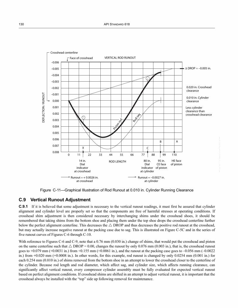
130 API STANDARD 618
--``,,,``,,`````,``,,,,,,,`,,`,,-`-`,,`,,`,`,,`---
Figure C-11—Graphical Illustration of Rod Runout at 0.010 in. Cylinder Running Clearance
–0.006
–0.005
–0.004
–0.003
–0.002
–0.001
0.000
0.001
0.002
0.003
0.004
0.005
0.006
0.007
0.0080 11 22 33 44 55 66 77 88 99 110
X C
AB
14 in.Dial
indicatorat crosshead
80 in.Dial
indicatorat cylinder
95 in.CE face
of piston
HE faceof piston
Runout + 0.0026 in.at crosshead
Runout = –0.0027 in.at cylinder
ROD LENGTH
0.020 in. Crossheadclearance
0.010 in. Cylinderclearance
Less cylinderclearance thancrosshead clearance
DROP –0.005 in.
DEF
LEC
TIO
N /
RUN
OU
T
Rod sa
g
Pist
on rod
Crosshead centerline
Face of crosshead VERTICAL ROD RUNOUT
C.9 Vertical Runout AdjustmentC.9.1 If it is believed that some adjustment is necessary to the vertical runout readings, it must first be assured that cylinder alignment and cylinder level are properly set so that the components are free of harmful stresses at operating conditions. If crosshead shim adjustment is then considered necessary by interchanging shims under the crosshead shoes, it should be remembered that taking shims from the bottom shoe and placing them under the top shoe drops the crosshead centerline further below the perfect alignment centerline. This decreases the DROP and thus decreases the positive rod runout at the crosshead, but may actually increase negative runout at the packing case due to sag. This is illustrated on Figure C-5C and in the series of five runout curves of Figures C-6 through C-10.
With reference to Figures C-6 and C-9, note that a 0.76 mm (0.030 in.) change of shims, that would put the crosshead and piston on the same centerline such that DROP = 0.00, changes the runout by only 0.076 mm (0.003 in.), that is, the crosshead runout goes to +0.079 mm (+0.0031 in.) from +0.155 mm (+0.0061 in.), and the runout at the packing case goes to –0.056 mm (–0.0022 in.) from +0.020 mm (+0.0008 in.). In other words, for this example, rod runout is changed by only 0.0254 mm (0.001 in.) for each 0.254 mm (0.010 in.) of shims removed from the bottom shoe in an attempt to lower the crosshead closer to the centerline of the cylinder. Because rod length and rod diameter, which affect sag, and cylinder size, which affects running clearance, can significantly affect vertical runout, every compressor cylinder assembly must be fully evaluated for expected vertical runout based on perfect alignment conditions. If crosshead shims are shifted in an attempt to adjust vertical runout, it is important that the crosshead always be installed with the “top” side up following removal for maintenance.
RECIPROCATING COMPRESSORS FOR PETROLEUM, CHEMICAL, AND GAS INDUSTRY SERVICES 131
--``,,,``,,`````,``,,,,,,,`,,`,,-`-`,,`,,`,`,,`---
These illustrations also demonstrate the importance of using the actual measured running clearances of the cylinder and crosshead when calculating and evaluating vertical rod runout since a change of cylinder running clearance will affect DROP which in turn affects vertical runout. For some combinations of cylinder size, rod length, and stroke, the cylinder clearance will have a greater effect on vertical rod runout than other combinations. As illustrated in Figures C-1 and C-2, it can be seen that the longer the stroke, the greater the runout; and the shorter the piston rod, the greater the runout, for the same DROP.
To see the effect of rider ring wear on vertical rod runout, use Figure C-10 as the initial reference and compare it to Figure C-9, which has a DROP of 0.254 mm (0.010 in.). The 0.254 mm (0.010 in.) drop is representative of 0.254 mm (0.010 in.) rider ring wear, which changes the vertical rod runout by 0.0254 mm (0.001 in.) to 0.030 mm (0.0012 in.) from 0.056 mm (0.0022 in.).
Where there is much concern about rod runout, each application needs to be studied carefully in order to fully understand what the vertical rod runout should be under conditions of perfect alignment in order to make the right decision and proper adjustment.
C.9.2 If crosshead shim adjustment has been considered necessary by interchanging shims under the crosshead shoes, the final arrangement shall be recorded in the as-built data sheet included in the operation and maintenance manual.

--``,,,``,,`````,``,,,,,,,`,,`,,-`-`,,`,,`,`,,`---
Annex D(informative)
Repairs to Gray or Nodular Iron Castings
D.1 ScopeThis annex covers repair procedures that have been successfully applied to gray and nodular iron castings for compressor cylinders and related parts in various services. These procedures are only briefly described for the purpose of reference by the purchaser and the vendor; detailed descriptions of the procedures are beyond the scope of this standard. Limitations on the use of the procedures are included. These procedures should be applied only after careful evaluation of the situation by the purchaser and the vendor. When the service conditions of the casting involve toxic or hazardous gases, an even more exhaustive evaluation should be made.
D.2 Repair methods and limitationsIn cylinders designed to handle gases having a mean molar mass (molecular weight) below 12, no repairs of any type shall be made to defects that result in leakage between the cylinder bore and the water jacket during hydrostatic testing. With the purchaser’s written approval, the repair methods specified in D.2.1 through D.2.3 may be used for compressor cylinders designed to compress gases with a mean molar mass of 12 or greater.
D.2.1 Areas in which hydrostatic testing shows leaks between the water jacket and the atmosphere or between the gas passage and the atmosphere or between the water jacket and the gas passage may be repaired by plugging per 6.13.6.5.2, or by approved procedures for vacuum-plus-pressure impregnating. Impregnating may be considered only for limited porosity-type leakage and only after hydrostatic testing of both the water jacket and the gas passage has proved the mechanical integrity of the casting.
D.2.2 Defects that show up on machined surfaces or in other areas where no leak is involved, may be repaired by iron plating. Such defects could include porosity in valve seats or head and cylinder end faces or out-of-tolerance of cylinder bores requiring a liner. Plating repairs are not acceptable in critical areas such as o-ring seating areas or surfaces swept by the compressor piston, where sharp edges could damage o-rings, piston rings, and so forth. If repair plating is used in other locations, no sharp corners shall be formed or left which could damage o-rings, etc. (see 6.13.6.5).
D.2.3 Damaged threaded holes in castings may be mechanically repaired by use of thread inserts or bushings.
D.3 TestsAfter any part is repaired in accordance with D.2.1, D.2.2, or D.2.3, the part shall be subjected to both a hydrostatic test and a gas test (see 8.3.2).
133--``,,,``,,`````,``,,,,,,,`,,`,,-`-`,,`,,`,`,,`---

--``,,,``,,`````,``,,,,,,,`,,`,,-`-`,,`,,`,`,,`---

Annex E(informative)
Purchaser’s Checklist
This checklist may be used to indicate the purchaser’s specific requirements when this standard indicates, with a bullet (•), that a decision or information is required from the purchaser.
The checklist should be used in conjunction with the data sheets (Annex A). Below, the purchaser should circle yes or no, or mark the appropriate space with an “X”, or fill in the requirements.
Note: The use of this checklist is optional where these Items are covered by a narrative specification.
Table E-1—Purchaser’s Checklist
Clause Question Answer2.3 Applicable standards:_________________________________________________________________________________5.1 Have units of measurement been specified? Yes No
6.1.3 Has equipment’s normal operating point been specified? Yes No6.1.5 Has the pressure design code been specified? Yes No6.1.6 Requirements and maximum allowable sound pressure level?
Requirement:________________________________________________________________________________________ Maximum allowable sound pressure level: ______________dB (A)
6.1.12 Area classification for electrical components? Applicable standards:_________________________________________________ Are local codes and regulations applicable? Yes No
6.1.17 Which details of an initial installation check shall be agreed by vendor and purchaser?_____________________________________________________________________Operating temperature alignment check? Yes No
6.1.20 Location and environmental conditions (see data sheet, page 2).6.1.21 Have utility streams been identified? Yes No6.1.22 Equipment’s normal operating point specified in the data sheet, page 1? Yes No
6.4 Values specified by the purchaser, based on his experience? for: maximum average piston speed: ____________________ m/s for: maximum speed: ________________________________ rpm
6.5.2 Is 100% unloading necessary? Yes No6.8.2.4 Is coating of the running bore of the cylinder required? Yes No
6.8.3.5.2 Self-contained, forced circulation, closed jacket cooling system to be furnished by the vendor: Yes No6.8.4.1.16 DN 12 indicator tap at each end of each cylinder? Yes No6.8.4.1.17 Have indicator valves been specified? Yes No6.12.1.1 Type of distance piece, specified in data sheet, page 8? Yes No6.9.1.9 Shall the vendor submit a written valve dynamics report? Yes No6.9.2.1 Is unloading to be specified (data sheet, page 3)? Yes No6.10.3.2 Purchaser requires wear bands? Yes No6.11.5 Are relief devices for crankcases required? Yes No
6.12.1.1 Has type of distance piece been specified (data sheet, page 8)? Yes No6.12.1.4/5 Provision for intermediate packing sealing gas required? Yes No6.12.2.1 Type of distance piece covers required: Mesh screens / Louvered Solid metal / Other6.12.2.3 Is higher partition differential pressure specified? Yes No6.12.2.4c Is distance piece purge or vacuum connection specified? Yes No6.13.1.1 Are shields in the crosshead housing over the oil return drains required? Yes No6.13.2.7 Closed liquid cooling system for packing to be supplied? Yes No6.13.1.6 Venting and buffer gas cups for cylinder pressure packing required? Yes No
6.14.2.1.3 Is special purpose oil system specified? Yes No6.14.2.2 Has the type of driver for auxiliary lube oil pump been specified on the data sheet, page 11? Yes No6.14.2.5 Has the heating device for oil reservoir been specified on the data sheet, page 5? Yes No6.14.2.6 Shall the relief valve for crankcase driven pump be mounted outside the crankcase? Yes No
6.14.2.1.10 Shall oil system be run in vendors shop? Yes No
--``,,,``,,`````,``,,,,,,,`,,`,,-`-`,,`,,`,`,,`---
135

136 API STANDARD 618
6.14.3.1.1 Has the type of lubricator for compressor cylinders and for the pressure packing lubrication been specified on the data sheet, page 9? Yes No
6.14.3.1.2 How shall lubricator to be driven? From crankshaft / Independently6.14.3.1.4 Is a heating device with thermostatic control for the lubricator reservoir required? Yes No6.14.3.1.6 Which alarm functions for cylinder and pressure packing lubrication are required?
for cylinder:______________________________________________________________________________for pressure packing:_______________________________________________________________________(See data sheet, page 16)
6.14.3.1.9 Are synthetic lubricants of compressor cylinder lubrication required and specified in data sheet, page 9? Yes No
6.14.3.2.2 Is an agreement for additional or alternative protection device for divider block lubrication required? Yes No
6.15.1.5 Are additional material tests specified? Yes No6.15.1.8 Has the presence and maximum amounts of corrosive, reactive or hazardous agents or
components in the process fluid been specified on the data sheet, page 2? Yes No
6.15.1.11 Has the amount of hydrogen sulfide been specified on the data sheet, page 2? Yes No6.15.5.12 Is additional inspection required for specific welds? Yes No6.15.5.13 Shall the proposed welding designs of fabricated cylinders be available for purchaser’s review? Yes No6.15.6.5 Shall purchaser be given notice of repairs to major components? Yes No6.15.7.5 Is 100 % radiography of butt welds or magnetic particle inspection or liquid inspection of welds
required? Yes No
6.15.7.6 Shall proposed connection sketches be submitted to the purchaser before fabrication? Yes No6.15.8.1 Has the minimum design metal temperature related to the expected operating conditions been
specified? Yes No
6.16.7 Shall US customary or SI units be shown on the nameplates? US customary units / SI units7.1.1.1 Has the type of driver been specified on the data sheet, page 1? Yes No7.1.1.5 Are there process-variations or start-up conditions that affect driver selection? Yes No7.1.1.6 Are the driver starting conditions specified on the data sheet? Yes No7.1.2.1 Have the type of motor, its characteristics and accessories been specified on the data sheets? Yes No7.1.2.3 Shall single bearing motors be provided with a temporary inboard support device? Yes No7.1.2.4 Has the reduced voltage for starting-torque requirements been specified? Yes No7.1.2.15 Shall hydrodynamic motor bearings be supplied with oil from compressor frame lubrication
system (data sheet, page 5)? Yes No
7.1.3.1 Has the standard for turbine drivers been specified? Yes No7.1.3.2 Is a separate lube oil system for turbine drive train in accordance with ISO 10 438 (or API Std
614) required? Yes No
7.2.1.3 Are couplings required to comply with API Std 671 (data sheet, page 4)? Yes No7.2.1.7 Are couplings for auxiliary drives required to comply with API Std 671 (data sheet, page 4)? Yes No7.2.2.1 Has the standard for guards been specified on data sheet, page 4? Yes No7.3.1 Has the standard for gear units been specified on data sheet, page 4? Yes No
7.5.1.1 Has the type of mounting plates been specified on the data sheet, page 4? Yes No7.5.3.5 Have chock blocks been specified on the data sheet, page 4? Yes No7.5.3.9 Have leveling plates been specified on data sheet, page 4? Yes No7.5.4.1 Has the major equipment to be mounted on a baseplate been indicated on the data sheet, page 4? Yes No7.5.4.8 Has a baseplate suitable for column mounting been specified on the data sheet, page 4? Yes No7.5.4.9 Shall the baseplate be designed to facilitate optical, laser, or other accurate leveling in the field? Yes No7.5.4.14 Shall a dynamic response analysis of the skid be performed? Yes No7.5.4.15 Shall sub-soleplates be provided with the baseplate? Yes No7.5.5.1 Have soleplates or rails been specified on the data sheet, page 4? Yes No7.5.5.4 Shall sub-soleplates be supplied for soleplates? Yes No7.6.1.2 Are all auxiliary system instrumentation be provided by the vendor specified? Yes No7.6.2.1 Which sensing lines handling hazardous fluids require transduced
signals?____________________________________________________________________________________________Source of the control signal and its sensitivity and range?_____________________________________________________
7.6.2.2 Has the configuration of the control system been specified? Yes No
Table E-1—Purchaser’s Checklist (Continued)
Clause Question Answer
--``,,,``,,`````,``,,,,,,,`,,`,,-`-`,,`,,`,`,,`---

RECIPROCATING COMPRESSORS FOR PETROLEUM, CHEMICAL, AND GAS INDUSTRY SERVICES 137
7.6.2.4 Is an automatic loading-delay interlock required? Yes No7.6.4.1 Have instruments for local, gauge board, or instrument panel been specified? Yes No7.6.4.2 Has a tachometer to indicate compressor speed been specified on the data sheet, page 17? Yes No
7.6.4.3.3 Have temperature detectors for packing been specified on the data sheet, page 16? Yes No7.6.4.3.4 Have temperature detectors for main bearings and valves been specified on data sheet, page 16? Yes No7.6.6.4 Has the extent of the alarm/shutdown system to be supplied by the vendor been specified on data
sheet, page 16? Yes No
7.6.6.6 Has the design of alarm and shutdown circuits been specified? Yes No7.6.6.7 Have high temperature alarms for crosshead pins been specified on data sheet, page 16? Yes No7.6.7.1 Shall the vendor furnish and mount vibration detection and transducing devices? Yes No7.6.7.2 Shall a non-contacting proximity device to measure vertical movement of each piston rod be
installed? Yes No
7.6.7.3 Shall a one-event-per-revolution mark be provided on the crankshaft? Yes No7.6.7.4 Shall the vendor provide piston rod drop detectors? Yes No7.6.8 Shall the vendor supply a temperature monitoring system in accordance with API Std 670? Yes No
7.7.1.2 Has the extent of piping system to be supplied by the vendor been specified on data sheet, page 4? Yes No7.7.1.4 Shall piping, pulsation suppression devices and knockout vessels be arranged for heat tracing and
insulation (see 7.9.5.1.17)? Yes No
7.7.1.6 Shall the vendor review the drawings of all upstream and downstream piping, appurtenances, vessels and supports? Yes No
7.7.1.13 Special requirements for piping, flanges, valves and other appurtenances for hydrogen, hydrogen sulphide or toxic services?____________________________________________________________________________________________
7.7.2.5 Is a continuous through flow for instrument sensing lines to safety switches required? Yes No7.7.4.3 Shall coolant piping on the compressor be furnished by the vendor? Yes No7.7.6.1 Extent of process piping to be furnished by the
vendor?____________________________________________________________________________________________7.7.6.3 Have design, location, and orientation of start-up screens been agreed? Yes No7.7.6.4 Shall a removable spool piece for start-up screens be supplied? Yes No7.8.1.1 Has the type of intercoolers to be furnished by the vendor been specified? Yes No7.8.1.2 Has the type of aftercoolers to be furnished by the vendor been specified? Yes No7.8.2.1 Shall liquid separation and collection facilities be provided? Yes No7.8.2.7 Shall an automatic drainage system be provided? Yes No7.8.2.8 Shall level indicator and alarm and shutdown devices be provided?
Has piping between compressor stages and the intercoolers and aftercoolers furnished by the vendor been specified on data sheet, page 4?
Yes No
Yes No7.9.2 Have alternate gases, conditions of service, or start-up been specified? Yes No
7.9.3.1 Will compressor be operated in conjunction with other compressor units (data sheet, page 4)? Yes No7.9.3.2 Has Design Approach 1 been specified (data sheet, page 4)? Yes No
7.9.4.1.2 Shall the analysis be performed by the vendor or a third party? Vendor / Third party7.9.4.2.5.2.2.4 Has criteria for flow pulsations in systems with sensitive elements been agreed upon? Yes No7.9.4.2.5.2.5.2 Shall a piping system flexibility analysis be performed? Yes No
7.9.5.11 Shall the pulsation suppressors be stamped with the symbol of the specified pressure vessel code? Yes No7.9.5.1.4 Shall butt welds of pulsation suppression devices be 100% radiographed? Yes No7.9.5.1.7 Shall a final moisture removal section be included in the suction suppression device? Yes No7.9.5.1.10 Has purchaser approved use of circular notched baffles? Yes No7.9.5.1.11 Shall a thermowell connection for the cylinder nozzle of each suction pulsation suppressor be
provided? Yes No
7.9.5.1.17 Has provision for insulation at pulsation suppression devices been specified on the data sheet, page 14? Yes No
7.9.5.1.20 Shall internals of carbon steel suppressors be coated with phenolic or vinyl resin? Yes No7.9.5.1.22 Shall dynamic and static stresses from pulsation-induced forces be analyzed? Yes No
7.9.6 Shall the vendor supply supports for the pulsation suppression devices and for vendor supplied piping? Yes No
7.10.1 Has purchaser specified special design details for air intake filters? Yes No7.11.2 Shall hydraulic tensioning tools be included in special tools? Yes No
Table E-1—Purchaser’s Checklist (Continued)
Clause Question Answer
--``,,,``,,`````,``,,,,,,,`,,`,,-`-`,,`,,`,`,,`---

138 API STANDARD 618
--``,,,``,,`````,``,,,,,,,`,,`,,-`-`,,`,,`,`,,`---
7.11.5 Shall the compressor be fitted with a device to lock the shaft in position during maintenance? Yes No8.1.2 Is purchaser’s inspector to submit completed inspection checklist before shipment? Yes No8.1.6 Has the extent of purchaser’s participation in the inspection and testing and amount of advance
notification been specified on the data sheet, page 9? Yes No
8.2.1.1 f Shall the vendor keep available for at least 20 years final-assembly, maintenance and running clearances? Yes No
8.2.1.3 Which parts shall be subjected to surface and subsurface examination?:________________________________________________________________________________________and which type of examination is required?: ________________________________________________________________
8.2.2.1.1 Required radiographic, ultrasonic, magnetic particle or liquid penetrant inspection of welds or materials? — radiographic — ultrasonic — magnetic particle — liquid penetrant
Yes NoYes NoYes NoYes No
8.2.3.2 Shall the oil system be run in the manufacturer’s shop? Yes No8.2.3.3 Has inspection for cleanliness of the equipment and all piping and appurtenances by the purchaser
been specified on the data sheet, page 9? Yes No
8.2.3.4 Shall the hardness of parts, welds and heat-affected zones be tested? Yes No8.3.3.2 Has a 4-hour running test of the compressor been specified on the data sheet, page 9? Yes No8.3.3.3 Is a 4-hour mechanical running test prior to shipment required for packaged units, including
auxiliary system packages? Yes No
8.3.3.6 Is an operational test and a 4-hour mechanical running test prior to shipment for auxiliary system consoles required? Yes No
8.3.3.7 Is dismantling for inspection required? Yes No8.3.4.2 Shall all machine-mounted equipment, prefabricated piping and appurtenances furnished by the
vendor be fitted and assembled in the vendor’s shop? Yes No
8.3.4.4 Shall the compressor be performance tested in accordance with ISO 1217? Yes No8.4.1 Time for storage for a longer period than 6 months?__________________________________________________________8.4.14 Shall the equipment be packed for domestic or export shipment? Domestic / Export9.2.3m Special requirements for long term storage of spare parts?_____________________________________________________9.2.3s Is a list of similarly installed machines to be attached to the proposal required? Yes No9.3.1.3 Has time allowed for the purchaser to review vendor’s data been specified and agreed? (see
VDDR form in Annex F) Yes No
9.3.3.1 Shall the vendor submit performance curves or tables etc.? Yes No9.3.3.3 Shall the vendor furnish data required for independent rod-load, gas-load and rod-load reversal
calculations? Yes No
9.3.3.4 Shall the effect of valve failure on rod loads and reversals be calculated and furnished? Yes No
Table E-1—Purchaser’s Checklist (Continued)
Clause Question Answer

09
Annex F(normative)
Vendor Drawing and Data Requirements
F.1 GeneralThis annex consists of a sample vendor drawing and data requirement form (VDDR), followed by a list of possible Items that may be included on the form and representative descriptions of those Items. Since different manufacturers will use different names for the same drawing, the Items in the description column of the VDDR should be modified in the early stages of the order using the drawing names supplied by the manufacturer.
Insert VDDR form here (see Errata 1 at end of document).
F.2 Items for VDDR FormItems to be entered on the VDDR should be selected from the following list as appropriate. However, this list is not necessarily all-inclusive.
1. Certified dimensional outline drawing (general arrangement) and list of connections.2. Foundation plan showing anchor bolt locations.3. Allowable flange loading (either cylinder or pulsation suppression device) and coordinates. 4. Driver outline.5. Drive arrangement drawing.6. Dimensional outline for all vendor-supplied major accessory equipment.7. Performance data.8. Pressure packing drawing(s).9. Gas load, rod load, and crosshead load reversal and duration charts. 10. Starting torque versus speed curves (for driver and compressor.)11. Motor driver performance characteristics.12. Tabulation of utility requirements.13. List of unsafe or undesirable speeds.14. Gear data.15. Other driver data.16. Shaft coupling assembly drawing and bill of materials.17. Weld procedures for fabrication and repair, including those for pulsation suppression devices.18. Intercooler and aftercooler data.19. Parts list with sectional drawings.20. “Start-up” spares list. 21. Recommended normal maintenance spare parts.22. Process schematic.23. Frame and cylinder lube oil schematics and bills of materials.24. Lube oil system assembly drawings and list of connections.25. Lube oil system component drawings and data.26. Cooling system schematics and bills of materials.27. Cooling system assembly drawings and list of connections.28. Cooling system component drawings and data.29. Distance piece vent, drain and buffer schematics and list of connections.30. Capacity control schematics and bill of materials.31. Instrumentation and electrical schematics and bills of materials.32. Instrumentation and electrical arrangement drawing and list of connections.33. Instrumentation and electrical wiring diagrams.34. Instrumentation set-point list.35. Instrumentation data sheets.36. Pulsation suppression device detail drawings and final pressure code calculations.
--``,,,``,,`````,``,,,,,,,`,,`,,-`-`,,`,,`,`,,`---
139

140 API STANDARD 618
37. Special tools list. 38. Fabrication, testing and delivery schedule.39. Drawing list.40. Weather protection and climatization required.41. Comments on purchaser’s piping and foundation drawings.42. Progress reports. 43. Torsional analysis report.44. Data for an independent torsional analysis.45. Acoustic and mechanical analysis report.46. Data required for third- party acoustic and mechanical analysis.47. Engineering analysis for fabricated cylinders. 48. Balancing data tabulation.49. Valve dynamics report. 50. Data for an independent valve dynamic analysis.51. Connection sketches.52. Shaft alignment diagram.53. As-built dimensions and data.54. Hydrostatic and gas test certificates. 55. Certified mechanical run test data (if test ordered).56. Certified performance test data (if test ordered).57. Non-destructive test procedures for fabricated cylinders.58. Procedures for special or optional tests (if tests ordered).59. Certified data from special or optional tests (if tests ordered).60. Certified mill test reports.61. Crankshaft ultrasonic test certificate.62. Valve leak test certificate.63. As-built data sheets.64. Installation manual.65. Operation and maintenance manual.66. Technical data manual.67. Procedures for preservation, packing and shipping.68. Shipping list.69. Material Safety Data Sheets.70. Quality plan.71. Control logic diagrams.
F.3 Description of VDDR Items1. Certified dimensional outline drawings (general arrangement) and tables include, but are not limited to, the following:
a. Size, type, rating, location and identification of all customer connections; including vents, drains, lubricating oil, conduits, conduit boxes, electrical and pneumatic junction boxes and instruments. The vendor’s plugged connections shall be identified. Details of special connections are required. See 6.8.2.4.1.b. The mass (weight) of each assembly, of the heaviest piece of equipment which must be handled for erection and of significant Items to be handled for maintenance.c. All principal dimensions, including those required for piping design, maintenance clearances and dismantling clearances, Including valve maintenance clearance if pulsation suppression devices are not supplied.d. Shaft center line height.e. Shaft end separation.f. Center of mass (gravity), vertical and plan location.g. Direction of rotation.h. When applicable, the make, size and type of couplings and the location of guards and their coverage.
--``,,,``,,`````,``,,,,,,,`,,`,,-`-`,,`,,`,`,,`---

RECIPROCATING COMPRESSORS FOR PETROLEUM, CHEMICAL, AND GAS INDUSTRY SERVICES 141
2. Foundation plan including:
a. Dimensions of mounting plates for the complete train and auxiliary systems complete with diameter, number and location of bolt holes and thickness of metal through which bolts must pass.b. Speed, critical speed (if any), c. Location and direction in the x, y, z-coordinate system of static and the first and second order dynamic (unbalanced) forces and moments. d. Location of the center of mass.e. Leveling jackscrew location.
3. Allowable flange loading (either cylinder or pulsation suppression device) and coordinates (see 6.6.5). Allowable flange loading(s) for all cylinder (or pulsation bottle) connections, including anticipated thermal movements referenced to a defined point, and x, y, z-coordinate system.4. Driver outline. Certified dimensional outline drawing for the driver and all its auxiliary equipment including:
a. Size, location, orientation and purpose of all customer connections, including conduit boxes, conduit, instrumentation and any piping or ducting.b. Type, rating and facing for any flanged connections.c. Size and location of anchor bolt holes and leveling jackscrews and thickness of sections through which bolts must pass.d. Total mass of each Item of equipment (driver and auxiliary equipment). plus loading diagrams, heaviest weight, and name of the part.e. Overall dimensions and all horizontal and vertical clearances necessary for dismantling and the approximate location of lifting lugs.f. Shaft center line height.g. Shaft end dimensions, plus tolerances for the coupling.h. Direction of rotation.
5. Drive arrangement drawing, including, but not limited to the following:
a. Flywheel data.b. Driver and mechanical transmission mass.c. Moments of inertia.d. Stator shift.e. Air gap.
6. Dimensional outline for all vendor supplied major accessory equipment.7. Performance data (see 9.3.3.1).8. Pressure packing drawing(s). (One for each packing type.)9. Gas load, rod load and crosshead load reversal and duration charts (see 9.3.3.2).10. Starting torque versus speed curves. (For driver and compressor—on the same chart.) Acceleration time (see 9.3.3.5).11. Motor driver performance characteristics and performance data including:
a. For induction motors 150 kW (200 hp) and smaller:1. Efficiency and power factors at one-half, three-quarter and full load.2. Speed-torque curves.
b. For induction motors larger than 150 kW (200 hp), certified test reports for all tests run and performance curves as follows:1. Time-current heating curve.2. Speed-torque curves at 70%, 80%, 90% and 100% of rated voltage.3. Efficiency and power factor curves from 0 to rated service factor.4. Current versus load curves from 0% – rated service factor.5. Current versus speed curves from 0% – 100% of rated speed.6. Permissible safe stall time and repeated start capability (hot and cold).
c. For synchronous motors.1. Speed-torque, current-speed and power factor-speed curves at 70%, 80%, 90% and 100% of rated voltage.2. Pull-in and pull-out torque.3. Permissible safe stall time and repeated start capability (hot and cold).4. Efficiency and power factor curves from 0 to rated service factor.
--``,,,``,,`````,``,,,,,,,`,,`,,-`-`,,`,,`,`,,`---

142 API STANDARD 618
5. Current pulsation-speed curve during normal acceleration.
12. Tabulation of utility requirements (may be on data sheets).13. List of unsafe or undesirable speeds (see 6.1.10).14. Gear Data.
a. Certified dimensional outline drawings and list of connections including:1. The size, rating, location and identification of all customer connections including vents, drains, lube oil, conduit boxes, junction boxes and instruments. 2. All principal dimensions, including those required for the purchaser’s foundation, piping design, maintenance clearances and dismantling clearances.3. Overall and handling masses.4. Shaft center line heights.5. Shaft end dimensions and tolerances for the couplings.6. Direction of rotation.7. Location of the center of mass of the gear unit.8. The size and location of anchor bolt holes and thickness of sections through which bolts must pass.9. Thermal and mechanical movements of casings and shafts.
b. Cross-sectional drawing and bill of materials including axial gear and pinion float.c. As-built data sheets including:
1. Data for torsional analysis.2. Lateral critical speed reports when specified.3. Certified mechanical running test data.
d. Certified gear manufacturer’s standard test data including gear contact test data.e. Optional test data and reports agreed upon by the purchaser and the gear manufacturer.f. Spare parts recommendations.
15. Other driver data, including:
a. Cross-sectional drawing and bill of materials, including the axial rotor float.b. As-built data sheets.c. Certified drawings of driver auxiliary systems including wiring diagrams for each auxiliary system supplied. The drawings shall clearly indicate the extent of the system to be supplied by the manufacturer and the extent to be supplied by others.d. Spare parts recommendations.e. Other driver data per driver VDDR.
16. Shaft coupling assembly drawing and bill of materials, including:
a. Allowable misalignment.b. Hydraulic mounting procedure.c. Shaft end gap and tolerance.d. Coupling guards.
17. Weld procedures for fabrication and/or repair, including those for pulsation suppression devices (see 7.9.3.3).18. Intercooler and aftercooler data, including, but not limited to:
a. Dimensional outline drawings.b. Data sheets (e.g., TEMA).c. Final calculation in accordance with the specified pressure code.
19. Parts list with sectional drawings. The parts list shall include pattern number, stock or production drawing numbers and the materials of construction. The list shall completely identify each part so that the purchaser may determine interchangeability of parts with other equipment furnished by the same manufacturer. Standard purchased Items shall be identified by the original manufacturer’s name and part number. Materials shall be identified as specified in 6.15.1.2.20. “Start-up” spares list (see 9.2.3i).21. Recommended normal maintenance spare parts (see 9.3.6).
--``,,,``,,`````,``,,,,,,,`,,`,,-`-`,,`,,`,`,,`---

RECIPROCATING COMPRESSORS FOR PETROLEUM, CHEMICAL, AND GAS INDUSTRY SERVICES 143
22. Process schematic:
Schematic diagram of the process fluids flowing through the machine, including:
a. Steady-state and transient gas flow rates, temperatures and pressures.b. Cooler heat loads.c. Pipe, tubing and valve sizes of equipment provided by the vendor.d. Instrumentation, safety devices and control schemes.e. Bill of materials.
23. Frame and cylinder lube oil schematics, including the following:
a. Steady-state and transient oil flows and pressures at each point.b. Control, alarm and trip settings (pressure and recommended temperatures).c. Total heat loads.d. Utility requirements, including electrical, water and air.e. Pipe, tubing and valve sizes.f. Instrumentation, safety devices and control schemes.g. Bills of materials.
24. Lube-oil system assembly drawings and list of connections.
Lube-oil system assembly and arrangement drawing(s), including size, rating and location of all customer connections.
25. Lube-oil system component drawings and data, including:
a. Outline and sectional drawings and data sheets for auxiliary pumps and drivers.b. Outline and sectional drawings and data sheets for coolers, filters and reservoir.c. Instrumentation.d. Spare parts lists and recommendations.
26. Cooling system schematics and bill of materials.
Cooling (including packing cooling) or heating schematic and bill of materials including cooling or heating fluid, fluid flows, pressure, pipe and valve sizes, instrumentation and orifice sizes.
27. Cooling system assembly drawings and list of connections.
Cooling (including packing cooling) or heating system assembly and arrangement drawing(s), including size, rating and location of all customer connections.
28. Cooling system component drawings and data.
a. Outline and sectional drawings and data sheets for pumps and coolers.b. Outline and sectional drawings and data sheets for coolers, filters and reservoir.c. Instrumentation.d. Spare parts lists and recommendations.
29. Distance piece vent, drain and buffer schematics and list of connections.
Distance piece vent, drain and purge schematic and bill of materials including fluid, fluid flows, pressure, pipe, tube and valve sizes and instrumentation.
30. Capacity control schematics and bill of materials.31. Instrumentation and electrical schematics and bills of materials for all systems, including pneumatic and hydraulic systems (including bar over device limit switch).32. Instrumentation and electrical arrangement drawing and list of connections, including pneumatic and hydraulic systems and including but not limited to:
a. Control panel general arrangement.b. Control panel certified outline.c. Control panel bill of materials.
--``,,,``,,`````,``,,,,,,,`,,`,,-`-`,,`,,`,`,,`---

144 API STANDARD 618
33. Instrumentation and electrical wiring diagrams for all systems.34. Instrumentation set-point list, including set points for all alarm, shutdown and control devices, including:
a. Vibration alarm and shutdown limits.b. Bearing temperature alarm and shutdown limits.c. Lube oil temperature alarm and shutdown limits.d. Lube oil pressure alarm and shutdown limits.e. Gas discharge temperature alarm and shutdown limits.f. Frame oil level alarm limit.g. Rod packing temperature alarm.h. Oil filter differential pressure alarm.i. Inlet separator level shutdown.j. Cylinder lubrication protection.k. Jacket water protection.
35. Instrumentation data sheets.36. Pulsation suppression device detail drawings and final pressure code calculations.37. Special tools list (see 7.11.1). List of special tools furnished for maintenance.38. Fabrication, testing and delivery schedule (see Item 42). Milestone fabrication, testing and delivery schedule, including vendor buyouts.39. Drawing list including latest revision numbers and dates.40. Weather protection and climatization required.41. Comments on purchaser’s piping and foundation drawings (see 6.1.16 and 7.7.1.6).42. Progress reports (see 9.3.5). See Item 38, including:
a. Planned and actual milestone dates.b. Engineering and manufacturing information on all major components.c. Details of causes of delays.
43. Torsional analysis report, (see 6.7.1 and 7.1.2.6) including but not limited to the following:
a. Complete description of method used.b. Graphic display of mass elastic system.c. Tabulation identifying the mass moment and torsional stiffness for each component identified in the mass elastic system.d. Graphic display of exciting forces versus speed and frequency.e. Graphic display of torsional critical speeds and deflections (mode shape diagram).f. Effects of proposed changes on analysis.g. Current pulsation analysis.
44. Data for an independent torsional analysis.45. Acoustic and mechanical analysis report, (see 7.9 and Annex M) including but not limited to:
a. Design approach (see 7.9.4.2.1) and method used (complete description), including description of design techniques used.b. Findings and comparison with permitted values.c. Effects of required modifications; and marked up drawings showing changes.d. Other information as required by Annex M.
46. Data required for third-party acoustic and mechanical analysis. Information described in Annex M.
Note: It is the purchaser’s responsibility to provide some of the information described.
47. Engineering analysis for fabricated cylinders (see 6.15.5.1).48. Balancing data tabulation. Listing of mass balance data for each throw, including piston, rod, crosshead, nuts, bushings, bearings and balance masses and including both design target masses and actual assembly masses. The allowable mass tolerance per throw shall be stated.49. Valve dynamics report (see 6.9.1.9).50. Data for an independent valve dynamic analysis.51. Connection sketches (see 6.15.7.6).
--``,,,``,,`````,``,,,,,,,`,,`,,-`-`,,`,,`,`,,`---

RECIPROCATING COMPRESSORS FOR PETROLEUM, CHEMICAL, AND GAS INDUSTRY SERVICES 145
52. Coupling-to-shaft alignment diagram. Shaft alignment diagrams (vertical and horizontal), including recommended coupling limits during operation. Note all shaft-end position changes and support growths from 15ºC (60°F) ambient reference temperature or other reference temperature specified by the purchaser. Include the recommended alignment method and cold setting targets.53. As-built dimensions and data, including:
a. Fits, clearances and runouts measured during final assembly.b. Nameplate data for each cylinder.c. Cylinder minimum and design clearances for each end of each cylinder.d. Volume of all clearance pockets, plugs or bottles installed on each cylinder.e. Crank angle phasing.
54. Hydrostatic and gas test certificates (see 8.3.2).55. Certified mechanical run test data (if test ordered).56. Certified performance test data (if test ordered).57. Non-destructive test procedures for fabricated cylinders.58. Procedures for any special or optional tests (if tests ordered).59. Certified data from special or optional tests (if test ordered) (see 8.3.4.1).60. Certified mill test reports of Items as agreed in the pre-commitment or pre-inspection meeting(s). Physical and chemical data.61. Crankshaft ultrasonic test certificate (see 8.2.2.3.3).62. Valve leak test certificate.63. As-built data sheets for compressor, gear, driver and auxiliary equipment, including gas data (see 6.1.23).64. Installation manual (see 9.3.7.2) describing the installation requirements for the complete train, including the drawings necessary for assembly of the equipment and location of field connections and including but not limited to the following:
a. Section 1—Compressor1. Items 1, 2, 3, 40, 52.2. Grouting (see 7.5.3.8).3. Setting equipment, rigging procedures, component masses and lifting diagram.4. Dismantling clearances.5. Preservation and storage requirements (see 8.4.2).6. Field assembly procedures, including frame and cylinder alignment requirements.
b. Section 2—Driver1. Storage and preservation.2. Setting gear, rigging procedures, component masses and lifting diagram.3. Piping recommendations.4. Composite outline drawing for driver including anchor bolt hole locations.5. Dismantling clearances.6. Thermal and mechanical movements of frame and shaft.7. Motor air gap data (see 7.1.2.13).
c. Section 3—Gear1. Storage and preservation.2. Setting gear, rigging procedures, component masses and lifting diagram.3. Piping recommendations.4. Composite outline drawing for gear including anchor bolt hole locations.5. Dismantling clearances.6. Thermal and mechanical movements of casing and shaft.
d. Section 4—Auxiliary equipment1. Storage and preservation.2. Setting equipment, rigging procedures, component masses and lifting diagram.3. Piping recommendation.
--``,,,``,,`````,``,,,,,,,`,,`,,-`-`,,`,,`,`,,`---

146 API STANDARD 618
--``,,,``,,`````,``,,,,,,,`,,`,,-`-`,,`,,`,`,,`---
65. Operation and maintenance manual, (see 9.3.7.3) describing the operating and maintenance procedures, requirements and limitations for the complete train and auxiliary equipment, including but not limited to the following:
a. Section 1— Operation1. Initial commissioning and start-up, including final tests and checks.2. Normal start-up.3. Normal shutdown.4. Emergency shutdown.5. Operating limits, including Item 13 above.6. Lube-oil recommendations, including injection rates and specifications.7. Routine operational procedures.8. Items 22, 30, 34 and 71.
b. Section 2—Maintenance, disassembly, repair and reassembly instructions for the complete train and auxiliary and accessory equipment including but not limited to the following:
1. Valve overhaul data.2. Cylinder overhaul data.3. Table of bolt torques. The required torque values or elongations for tensioning the valve cover, valve hold down bolts, connecting rod and main bearing bolts, piston and crosshead nuts, flange bolts and any other bolts that the vendor feels are critical. Data should be included for fasteners in both the lubricated and non-lubricated condition.4. Fits and clearances for wearing parts, recommended, maximum and minimum.5. Items 4, 8, 19, 21, 37, 48, 52, 53 and 63.6. Routine maintenance requirements.7. Maximum allowable crankshaft web deflection.
c. Section 3—Performance Data. Items 7, 9 and 10.d. Section 4—As Built Data. Items 53 and 63.e. Section 5—Drawing and Data
1. Drawings in the manual shall be for the specific equipment supplied. Typical drawings are unacceptable.2. Items 1, 5, 6, 8, 11, 15, 16, 19, 23, 24, 25, 26, 27, 28, 29, 30, 31, 32, 33, 36 and 39.
66. Technical Data Manual. See 9.3.7.4.
Technical and quality control data for technical support personnel for the complete train and auxiliary equipment, including but not limited to:
Items 1 – 16, 18 – 20, 23, 26, 29 – 31, 33 – 37, 39 – 40, 43, 45 – 49, 52 – 63.
67. Procedures for preservation, packing and shipping.68. Shipping list, including all major components that will ship separately.69. Material safety data sheets. Description of the hazardous and potentially hazardous materials included in the scope of supply.70. Quality plan. In accordance with ISO 9000 series.71. Control logic diagram (see 7.6.2.3).

--``,,,``,,`````,``,,,,,,,`,,`,,-`-`,,`,,`,`,,`---
Annex G(normative)
Figures and Schematics
G.1 GeneralThe schematics presented here illustrate the general philosophy and requirements of this standard and are typical of commonly used systems: they are not intended to include all details such as vent and drain details and minor piping connections to permit disassembly. The systems may be modified as necessary with the agreement of the purchaser and vendor.
Instrument piping and valving details are not shown on typical schematics. Such requirements, including on-line testing requirements, shall be agreed upon by the purchaser and vendor.
Requirements for all of the systems illustrated here are covered in the main text, as indicated by the cross-references in the notes accompanying each figure. Further elaboration on the details of pressure packing to minimize process gas emissions is given in Annex I.
G.2 Legend for SchematicsThe abbreviations and symbols used in the schematics in this annex are defined below.
G.2.1 FLOW DIAGRAM IDENTIFICATIONS LETTERS
Letter First Letter Subsequent LettersA Analysis AlarmC Conductivity (Electrical) ControllerD Density (Sp. Gr.) DifferentialE Voltage (EMF/Electrical) Element (Primary)F Flow Ratio (Fraction)G Gauging (Dimensional) Glass/GaugeH Hand Actuated (Manual) HighI Current (Amps) IndicatorL Level Light/LowO (Unclassified) Orifice (Restriction)P Pressure/Vacuum PointS Speed/Frequency Safety/SwitchT Temperature TransmitterV Vibration/Viscosity ValveY (Unclassified) Relay
147

148 API STANDARD 618
G.2.2 SYMBOLS
--``,,,
``,,`````,``,,,,,,,`,,`,,-`-`,,`,,`,`,,`---
RECIPROCATING COMPRESSORS FOR PETROLEUM, CHEMICAL, AND GAS INDUSTRY SERVICES 149
Figure G-1—Cylinder Cooling System
Figu
re G
-1—
Cylin
der C
oolin
g Sy
stem
s
Aux
. pum
pM
ain
pum
p
RO
Cool
erN
ote
6
TI
TCV
TIPS
L PI
PAL
Jack
et w
ater
syst
em fa
ilure
alar
m
Rese
rvoi
r
LG
Hea
ter Cl
eano
utco
nnec
tion
Dra
in
Fill
conn
ectio
nVe
nt
Nor
mal
leve
l
Not
e 5
Cons
ole
boun
dary
PLA
N D
JACK
ET W
ATER
CO
OLI
NG
SYS
TEM
Jack
et w
ater
coo
lant
con
sole
Wat
er c
onso
leou
tlet c
onne
ctio
nW
ater
con
sole
retu
rn c
onne
ctio
n
FIFI
FI
Dra
in
TITI
TI
Vent
Vent
Vent
Com
pres
sor A
TIFI
Vent
Vent
Dra
inD
rain
Dra
in
Vent
Not
e 8
Not
e 9
Not
e 8
Not
e 9
Cylinder
Framehead
Outer head
Cylinder
Framehead
Outer head
FIFI
FI
Dra
in
TITI
TI
Vent
Vent
Vent
Com
pres
sor B
TIFI
Vent
Vent
Dra
inD
rain
Dra
in
Vent
Cylinder
Framehead
Outer head
Cylinder
Framehead
Outer head
See
Not
e 2
PLA
N C
FORC
ED C
OO
LIN
G S
YSTE
M
Hea
ter
(see
cau
tion
note
)
Com
pres
sor
cylin
der
Uni
ons
TI
FI
Vent
Dra
in
OW
S
InO
ut
Not
es:
1. I
nstr
umen
tatio
n sh
own
is m
inim
um re
quire
d. T
he
pur
chas
er m
ay w
ish
to s
pec
ify a
dditi
onal
dev
ices
.2.
Flo
w th
roug
h cy
linde
rs m
ay b
e ei
ther
ser
ies
or
para
llel.
3. S
ee 6
.8.3
and
7.7
.4.
4. H
eate
rs u
sed
to p
rehe
at th
e cy
linde
r coo
ling
wat
er
(if n
eede
d to
mee
t the
requ
irem
ents
of 6
.8.3
.4.2
or
6.8.
3.5.
2) m
ay b
e el
ectr
ic, h
ot w
ater
, or s
team
. Th
ey
mus
t be
size
d to
take
into
acc
ount
hea
t los
ses
of
surf
ace
area
s of
the
cylin
der,
pip
e, a
nd fi
ttin
gs.
Goo
d ju
dgm
ent m
ust b
e ex
erci
sed
so th
at h
eate
rs w
ill n
ot
be
unde
rsiz
ed.
5. N
orm
al le
vel i
s ab
ove
the
high
est p
oint
of t
he
cylin
der p
ipin
g.6.
Coo
ler t
o ha
ve v
ents
and
dra
ins
on b
oth
shel
l and
tu
be
side
.7.
The
sys
tem
sho
wn
is ty
pic
al: m
ore
or le
ss
equi
pm
ent m
ay b
e fu
rnis
hed.
8. S
erie
s flo
w.
9. P
aral
lel fl
ow.
CA
UTI
ON
: W
hen
jack
et w
ater
tem
pera
ture
is to
be
cont
rolle
d by
ste
am s
par
ging
, the
follo
win
g p
reca
utio
ns s
houl
d b
e ob
serv
ed:
a. A
sile
nt (w
ater
-ham
mer
-cus
hion
typ
e) s
team
sp
arge
r sho
uld
be
pla
ced
in th
e w
ater
inle
t lin
e to
the
jack
et s
yste
m.
b. T
he w
ater
flow
rate
mus
t rem
ain
cons
tant
in
acco
rdan
ce w
ith th
e m
anuf
actu
rer's
requ
irem
ents
.c.
The
ste
am fl
ow in
to th
e w
ater
sho
uld
be
regu
late
d au
tom
atic
ally
to m
aint
ain
the
wat
er ja
cket
te
mpe
ratu
res
in a
ccor
danc
e w
ith 6
.8.3
.5.2
.
TILG
PLA
N B
THER
MO
SYPH
ON
SYS
TEM
Dra
in
OW
SVent
and
fill
conn
ectio
n
Cool
ant
leve
l
Ade
quat
eex
pans
ion
cham
ber
Com
pres
sor
cylin
der
Cool
er (fi
nned
pip
ety
pica
l, in
clin
ed fo
rm
axim
um e
ffect
iven
ess)
InOut
Vent
is s
tain
less
stee
l tub
e 1 /
2 in
chm
inim
um
LG
PLA
N A
STAT
IC (S
TAN
DPI
PE) S
YSTE
M
Dra
in
OW
S
Vent
and
fill
conn
ectio
n
Ade
quat
eex
pans
ion
cham
ber
with
full
mar
kCo
mpr
esso
rcy
linde
r
Cool
ant
leve
l
--``,,,``,,`````,``,,,,,,,`,,`,,-`-`,,`,,`,`,,`---

150 API STANDARD 618
Note 1: See 6.8.4.1.16
Note 2: This typical arrangement utilizes a 17-4 stainless steel sleeve as a standard compressor cylinder design. The sleeve is installed during manufacture of the cylinder, providing a high-strength, corrosion resistant passage through a minor boss area. The design installation arrange-ment of the 17-4 stainless steel sleeve may vary among manufacturers.
Figure G-2—Typical Cylinder Indicator Tap Connection
Wrench flats
Straightthreads
1/2" NPT
Cylinder body casting
Boss
Soft steelgasket
Liner
17-4 PH stainlesssteel sleeve
Cylinderwater jacket
--``,,,``,,`````,``,,,,,,,`,,`,,-`-`,,`,,`,`,,`---

RECIPROCATING COMPRESSORS FOR PETROLEUM, CHEMICAL, AND GAS INDUSTRY SERVICES 151
--``,,,``,,`````,``,,,,,,,`,,`,,-`-`,,`,,`,`,,`---
BB
CB
DP
P
P
A
D
E
FG
PP
CB
AFr
ame
end
Cro
sshe
ad Cro
sshe
ad g
uide
Inbo
ard
dist
ance
pie
ce
Acc
ess
open
ing
Out
boar
ddi
stan
ce p
iece
Acc
ess
open
ing
Oil
wip
er p
acki
ng(s
ee n
ote
3)
Part
ition
(Whe
n re
quire
d)
Oil
slin
ger
Pist
on ro
dPr
essu
repa
ckin
g
1
2 (s
ee n
ote
4)
Inte
rmed
iate
part
ition
(Whe
n re
quire
d)
(Whe
n re
quire
d)
Pist
on
Cylin
der
2 (s
ee n
ote
4)
BB
CB
DP
P
P
A
D
EP
FG
CB
AFr
ame
end
Cro
sshe
ad Cro
sshe
ad g
uide
Inbo
ard
dist
ance
pie
ce
Acc
ess
open
ing
Out
boar
ddi
stan
ce p
iece
Acc
ess
open
ing
(opt
iona
l)O
il w
iper
pac
king
(see
not
e 3)
Part
ition
(Whe
n re
quire
d)In
term
edia
tepa
rtiti
on
(Whe
n re
quire
d)
Oil
slin
ger
Pist
on ro
dPr
essu
repa
ckin
g
1
(Whe
n re
quire
d)
Pist
on
Cylin
der
BB
D
E
FG
CB
AFr
ame
end
Cro
sshe
ad Cro
sshe
ad g
uide
Dis
tanc
e pi
ece
Acc
ess
open
ing
Oil
wip
er p
acki
ng(s
ee n
ote
3)
Part
ition
(Whe
n re
quire
d)
Oil
slin
ger
Pist
on ro
dPr
essu
repa
ckin
g
1
(Whe
n re
quire
d)
Pist
on
Cylin
der
D
E
FG
CB
BA
Fram
e en
d
Cro
sshe
ad Cro
sshe
ad g
uide
Dis
tanc
epi
ece
Acc
ess
open
ing
Oil
wip
er p
acki
ng(s
ee n
ote
3)
Part
ition
Pist
on ro
dPr
essu
repa
ckin
g
1
(Whe
n re
quire
d)
(Whe
n re
quire
d)
Pist
on
Cylin
der
TYPE
ASH
ORT
SIN
GLE
-CO
MPA
RTM
ENT
DIS
TAN
CE P
IECE
(MAY
BE
INTE
GRA
L W
ITH
CRO
SSH
EAD
GU
IDE
OR
CRA
NK
END
HEA
D)
TYPE
BLO
NG
SIN
GLE
-CO
MPA
RTM
ENT
DIS
TAN
CE P
IECE
(SU
FFIC
IEN
T LE
NG
TH F
OR
OIL
SLI
NG
ER T
RAVE
L)
TYPE
DSH
ORT
TW
O-C
OM
PART
MEN
T O
R D
OU
BLE
DIS
TAN
CE P
IECE
ARR
AN
GEM
ENT
(INBO
ARD
DIS
TAN
CE P
IECE
OF
SUFF
ICIE
NT
LEN
GTH
FO
R O
IL S
LIN
GER
TRA
VEL)
TYPE
CLO
NG
TW
O-C
OM
PART
MEN
T O
R D
OU
BLE
DIS
TAN
CE P
IECE
ARR
AN
GEM
ENT
(INBO
ARD
AN
D O
UTB
OA
RD D
ISTA
NCE
PIE
CES
EACH
OF
SUFF
ICIE
NT
LEN
GTH
FO
R O
IL S
LIN
GER
TRA
VEL)
Lege
nd:
1. S
eal o
r buff
er p
acki
ng, d
ista
nce
piec
e2.
Int
erm
edia
te s
eal o
r buff
er p
acki
ng, d
ista
nce
piec
e (s
olid
acc
ess
cove
rs re
quire
d)
Conn
ectio
ns (s
ee 6
.12.
2 fo
r siz
es):
A
Vent
, dis
tanc
e pi
ece
B P
urge
, buff
er, o
r pre
ssur
e, p
acki
ng o
r dis
tanc
e pi
ece
C L
ube,
pre
ssur
e pa
ckin
gD
Dra
in, d
ista
nce
piec
eE
Coo
lant
out
, pre
ssur
e pa
ckin
gF
Coo
lant
in, p
ress
ure
pack
ing
G C
omm
on v
ent a
nd d
rain
, pre
ssur
e pa
ckin
gP
Plu
gged
con
nect
ion
Not
es:
1. S
ee 6
.10
and
6.1
3.1.
3.2.
The
ori
enta
tion
of d
ista
nce-
pie
ce a
nd p
acki
ng-fl
ang
e/ca
se c
onne
ctio
ns
may
var
y d
epen
din
g o
n th
e in
div
idua
l dis
tanc
e p
iece
and
the
typ
e of
p
acki
ng c
ase
used
.
3. T
he o
il w
iper
pac
king
may
be
loca
ted
in th
e d
ista
nce
pie
ce o
n th
e ot
her
sid
e of
the
par
titi
on fr
om th
at s
how
n, a
nd w
ould
be
an in
tegr
al a
ssem
bly
w
ith
the
seal
or b
uffer
pac
king
(1).
4. T
he in
term
edia
te s
eal o
r buff
er p
acki
ng (2
) may
be
loca
ted
in th
e ou
tboa
rd
dis
tanc
e p
iece
on
the
othe
r sid
e of
the
par
titi
on fr
om th
at s
how
n.
Figure G-3—Distance Piece and Packing Arrangements

152 API STANDARD 618
Figure G-4—Typical Self-Contained Cooling System for Piston Rod Pressure Packing
Note 1: The instrumentation shown is the minimum required. The purchaser may wish to specify additional devices.Note 2: For cooling medium other than water system design shall be mutually agreed upon between purchaser and the vendor.Note 3: See 6.13.Note 4: If a packing cooling console is not supplied, individual strainers are required (see 6.13.2.6).Note 5: Cooler to have vents and drains on both shell and tube side.Note 6: Normal level is above the highest point of the piping on the compressor cylinders.Note 7: The system shown is typical: more or less equipment may be provided.
--``,,,``,,`````,``,,,,,,,`,,`,,-`-`,,`,,`,`,,`---

RECIPROCATING COMPRESSORS FOR PETROLEUM, CHEMICAL, AND GAS INDUSTRY SERVICES 153
--``,,,``,,`````,``,,,,,,,`,,`,,-`-`,,`,,`,`,,`---
Figure G-5—Typical Pressurized Frame Lube Oil System
TI
LG
CRANKCASE OIL RESERVOIR
Console boundary
RO
Vent
Drain
Oilfilter
Vent
Drain
Oilfilter
TCV
PDAH
PDSH
RO
TI
AUX. PUMP
OILCOOLER
Motor
PRV
Consolereturn connection
RO
PI PSLPSL
PAL
PSLL
I
Shutdown I
Aux. pump start
Framebreather
PRV
LALLSL
Drain
OWS
Crankcasedrain
Inletstrainer
Mainpump
FI
Maindrive
motor
Heater
Consolesupplyconnections
Notes:1. Instrumentation shown is the minimum required. The purchaser may wish to specify additional devices.2. See 6.14.2.3. Cooler to have vents and drains on both shell and tube side.4. The system shown is typical: more or less equipment may be provided.5. Check valve with RO on main pump is optional. The RO is for priming the main pump.6. See 6.14.2.4.7. Six-port continuous-flow transfer valve, manually operated.
Note 7
Note 6
Note 6
Note 5
Note 3Manualoverride
Oil systemextended to driver(if specified)
Gravity drain tocrankcase (when oilsystem extended todriver is specified)

154 API STANDARD 618
--``,,,``,,`````,``,,,,,,,`,,`,,-`-`,,`,,`,`,,`---
Figure G-6—Conceptual Direct Rod Connection
Body (Crosshead)
Bolt (Piston rod)
Location ofthread-root prestress-force
Jambnut
Figure G-7—Conceptual Indirect Rod Connection
Body (Crosshead)
Bolt (Piston rod)
Figure G-8—Conceptual Indirect Clamped Rod Connection
Body (Crosshead)
Bolt (Piston rod)
Clamping Nut

RECIPROCATING COMPRESSORS FOR PETROLEUM, CHEMICAL, AND GAS INDUSTRY SERVICES 155
Figure G-9—Tightening Diagram (Bolt–Bracing–Diagram)
Force
Fp
Operating Forceduring compression stroke
Prestress Force
of Fastening
Operating Forceduring tension stroke
Fr
Fo
Body (Crosshead)characteristic
Bolt (Piston rod)characteristic
Fa
Fp
Fm
Elongation
Fo
Definitions: Fp = Prestress of the Fastening
Fo
= Operating Force (under MAWP-condition, or at maximum allowable continuous rod load) F
a = amplitude of the alternating Force (in the bolt-shaft and thread)
Fm
= max Force (in the bolt-shaft and thread) F
r= min remaining Force in the fastening
Smax
= max stress in the thread-root or any other area of the bolt due to Fm
Sa = alternating Stress at the thread-root section due to F
a
--``,,,``,,`````,``,,,,,,,`,,`,,-`-`,,`,,`,`,,`---

--``,,,``,,`````,``,,,,,,,`,,`,,-`-`,,`,,`,`,,`---

Annex H(Informative)
Table H-1—Material Specifications for Reciprocating Compressor Parts
Part Material FormFrame Cast iron CastCrankshafts Steel ForgedConnecting rods Steel ForgedCrossheads Steel Bar stock, forged, or cast
Ductile iron CastCrosshead pins Steel Forged or bar stockDistance pieces Cast iron CastCylinders Steel Cast, forged, or fabricated
Stainless steel Cast or fabricatedNodular iron CastGray iron Cast
Cylinder liners Steel TubingStainless Steel CastNi-resist CastNodular iron CastGray iron Cast
Cylinder heads Steel Cast, forged, or fabricatedStainless steel PlateNodular iron CastGray iron Cast
Pistons Steel Forged, cast, bar stock, or fabricatedCast iron CastAluminum Forged or cast
Piston rods and tailrods Steel Forged or bar stockStainless Steel Bar stock
Piston rod nuts Steel Forged or bar stockStainless Steel Forged or bar stock
Valve seats and guards Steel Plate or bar stockStainless steel Plate, bar stock, or castNodular iron CastCast iron Cast
Valve plates Stainless steel PlateNon-metallic Molded
Valve springs Steel DrawnStainless steel Formed
Packing cases Steel Bar stockStainless steel Bar stockCast iron Cast
Packing case flange Steel Forged, bar stock, or platePiston rings, wear bands, and packing rings Metallic Cast or Bar Stock
Non-metallic Molded or Sintered
Materials for Major Component Parts
157--``,,,``,,`````,``,,,,,,,`,,`,,-`-`,,`,,`,`,,`---

--``,,,``,,`````,``,,,,,,,`,,`,,-`-`,,`,,`,`,,`---

--
Annex I(informative)
Distance Piece Vent, Drain and Buffer Systems to Minimize Process Gas Leakage
I.1 ScopeThis annex contains a general philosophy for the design of reciprocating compressor distance piece vent, drain, and gas buffer systems, which are typical of systems commonly used to minimize process gas leakage. This annex is not intended to cover all possible situations; rather, it focuses on providing an approach, which can be used to design successful systems.
Note: The piping, tubing, and components external to the distance piece may be supplied by either the purchaser or vendor. It is good practice for the vendor and purchaser to discuss the vent and drain system, and agree on its design (see 6.12.2).
Instrument piping and valving details are not shown on typical schematics. Such requirements, including on-line testing requirements, should be agreed upon by the purchaser and vendor.
I.2 Abbreviation and SymbolsThe abbreviations and symbols used in the schematics in this annex are shown in Annex G.
I.3 The Purpose of Distance Piece Vent, Drain and Buffer systemsA distance piece vent and drain system working in conjunction with packing, buffer system and partitions, accomplishes several functions, including:
a. confining and collecting the normal leakage from compressor rod pressure packing and carrying the leakage to a safe location;b. preventing process gas, toxic gas or hazardous gas leakage into the area around the machine;c. preventing contamination of the crankcase lube oil;d. atmospheric fugitive emission control;e. confining and collecting large leakage in the event of compressor pressure packing failure, and directing the leakage to a safe location;f. helping to prevent an explosive atmosphere from developing in the crankcase;g. preventing excessive liquid accumulation in the distance piece;h. avoiding gas leakage to sewer systems;i. allowing the operator to monitor and determine the condition of compressor rod pressure packing.
I.4 Minimizing Process Gas LeakageFigures I-1 and I-2 illustrate the arrangement of two typical distance piece types that may be used when it is necessary to reduce the leakage of process gas to a minimum. The accompanying packing detail drawing, Figure I-3, shows the arrangement of the packing rings and the direction of flow and typical pressures of the buffer gas.
Side-loaded packing rings provide constant mechanical axial loading towards the sealing face of the cup. This mechanical axial loading, added to a buffer gas pressure at least 1 bar higher than the disposal pressure, hold the rings positively against their sealing faces minimizing buffer gas leakage and, at the same time, assures that all the process gas that leaks past the cylinder pressure packing cups will be forced out into the disposal system (for example, the flare) through the vent.
When proper differential buffer gas pressures are maintained, process gas leakage into the distance pieces is minimal; process gas is prevented from entering the compressor frame. To minimize gas emissions, special packing and long distance pieces should be specified (see 6.13.1.6).
159``,,,``,,`````,``,,,,,,,`,,`,,-`-`,,`,,`,`,,`---

160 API STANDARD 618
I.5 Design ConsiderationIn addition to meeting the purposes described in I.2 the following factors should be considered when designing in designing a distance piece vent, drain and buffer system:
a. Small diameter vent and drain piping will tend to foul and corrode over time, inhibiting their function. Consider using large [e.g., DN 50 (NPS 2)] vent and drain headers and corrosion-resistant materials.b. On two-compartment distance piece systems, external cross connections between the inner and outer compartment vents and drains should be avoided.c. On multiple machine systems, it should be possible to isolate each machine for maintenance.d. Effective control of gas leakage requires the specification of gasketed solid metal covers on distance pieces (see 6.12.2.1).e. Where vents, drains, liquid collection pots and distance pieces are connected to disposal systems, such as a flare or closed drain system, they should be designed to withstand the maximum disposal system pressure (e.g., flare back pressure under relieving conditions). See 6.12.2.3.
Note: Distance pieces are typically designed for a maximum gauge pressure of 2 bar (25 psi). Special designs are required for higher pressures.
f. Typically, the common vent and drain from the pressure packing (connection G in Figure I-1 and I-2) will be carrying a mixture of liquid and gas. The system should be designed to separate these phases to avoid liquid blockage of the vent system.g. Leaks from the stems of valve unloaders and clearance pockets may also need to be collected and controlled. These can be integrated with the distance piece vent and drain system.h. There is concern about the reliability of check valves in safety situations, particularly in low pressure systems such as distance piece vent and drain systems where there is any mixture of gas and liquids. Check valve use should be avoided, where possible.i. Except for the pressure packing combined vent and drain, which is a pressure driven flow, separate vent and drain lines are necessary between the distance piece and liquid collection pot to pressure balance the system and allow free drainage. Sloped headers, without pockets, assist draining.j. Large diameter tubing [20 mm (3/4 in.) OD minimum] can be used between the individual distance pieces and the vent and drain headers. This usually results in a neat, easily maintained installation compared to a piping system.k. Manifolding and cross-connections with drains and blowoffs from other equipment should be avoided.l. The buffer gas purge pressure must be limited to the maximum allowable pressure for the distance piece components (see 6.10.4). Some buffer gas will flow into the compressor frame. Frame venting must allow an outlet for this flow (see Figure G-5).m. Pneumatic trip systems internal to the frame (e.g., crosshead pin temperature) should be energized with nitrogen rather than air to assist in maintaining an inert atmosphere in the crankcase.n. Effective establishment of an inert atmosphere in the crankcase will necessitate special maintenance safety procedures.o. Where climatic conditions require, drains should be heat-traced and insulated.p. Under total packing failure, it should not be possible to over-pressure the distance piece (see 6.10.4 and 6.10.5). If the vent area is not sufficient, additional venting to a safe location by way of emergency pressure relief valves or spring-loaded pressure relief doors may be required.q. Buffer gas purge rates are typically sized for a flow rate of 0.03 m3/h (10 standard ft2/h) per packing set [may reach 0.2 m3/h (65 standard ft2/h) per packing set on startup] and are fitted with flow indicators.
--``,,,``,,`````,``,,,,,,,`,,`,,-`-`,,`,,`,`,,`---

RECIPROCATING COMPRESSORS FOR PETROLEUM, CHEMICAL, AND GAS INDUSTRY SERVICES 161
Figure I-1—Typical Buffered Single Compartment Distance Piece Vent, Drain, and Buffer Arrangement to Minimize Process Gas Leakage
Not
es:
1. S
ee 6
.12.
2 an
d 6
.13.
1.6
2. B
uffer
gas
pre
ssur
e m
ust b
e at
leas
t 1 b
ar (1
5 p
ound
s p
er s
qua
re in
ch) h
ighe
r tha
n th
e d
isp
osal
sys
tem
pre
ssur
e at
con
nect
ion
A o
r co
nnec
tion
G (i
n th
e ou
tboa
rd d
ista
nce
pie
ce)
whi
chev
er is
hig
her.
3. T
he o
il w
iper
pac
king
may
be
on th
e d
ista
nce
pie
ce s
ide
of th
e p
arti
tion
and
inte
gral
wit
h th
e b
uffer
sea
l pac
king
(1).
4. I
n so
me
case
s, lo
wer
buff
er a
nd v
ent
pre
ssur
es th
an th
e ex
amp
les
show
n in
the
pac
king
det
ails
may
be
nece
ssar
y to
ac
com
odat
e th
e p
ress
ure
limit
atio
ns o
f lar
ge
dis
tanc
e p
iece
s.5.
Sev
eral
oth
er d
ista
nce
pie
ce a
nd p
acki
ng
arra
ngem
ents
for p
ress
urin
g, b
uffer
ing,
p
urgi
ng, a
nd v
enti
ng a
re p
ossi
ble
, and
the
arra
ngem
ent t
o b
e us
ed s
houl
d b
e ag
reed
up
on
bet
wee
n th
e p
urch
aser
and
the
vend
or.
6. S
ome
user
s m
ay c
hoos
e to
shu
tdow
n as
wel
l as
ala
rm in
som
e ca
ses.
7. F
ixed
pre
ssur
e co
ntro
l or d
iffer
enti
al p
ress
ure
cont
rol d
epen
din
g o
n th
e va
riab
ility
of t
he
dis
pos
al s
yste
m.
8. K
eep
the
dis
pos
al fr
om th
e d
ista
nce
pie
ce
liqui
d c
olle
ctio
n p
ot a
nd p
acki
ng le
akag
e liq
uid
co
llect
ion
sep
arat
e. T
he d
ista
nce
pie
ce li
qui
d
colle
ctio
n p
ot s
houl
d b
e co
nnec
ted
to a
vap
or
reco
very
sys
tem
or a
low
pre
ssur
e fla
re s
yste
m.
The
pac
king
leak
age
liqui
d c
olle
ctio
n p
ot c
an
be
conn
ecte
d to
eit
her a
vap
or re
cove
ry, a
low
p
ress
ure
flare
, or a
con
vent
iona
l flar
e sy
stem
.9.
To
or fr
om o
ther
cyl
ind
ers
on th
e sa
me
mac
hine
. W
hen
diff
eren
t cyl
ind
ers
on a
co
mm
on fr
ame
are
in d
iffer
ent s
ervi
ces,
in
div
idua
l iso
lati
on o
f ven
ts a
nd d
rain
s m
ay b
e re
qui
red.
Inte
nded
Mod
e of
Ope
ratio
n•
The
dist
ance
pie
ce o
pera
tes
at d
ispo
sal s
yste
m p
ress
ure-
usua
lly a
gau
ge p
ress
ure
of 0
.15
to 0
.4 b
ar (2
to 5
po
unds
per
squ
are
inch
) an
d is
fille
d w
ith a
mix
ture
of i
nert
buff
er g
as a
nd p
roce
ss g
as.
The
pack
ing
vent
TI
allo
ws
mon
itorin
g of
the
pack
ing
cond
ition
. Th
ere
is n
orm
ally
no
proc
ess
gas
leak
age
into
the
dist
ance
pi
ece.
Und
er a
bnor
mal
con
ditio
ns (s
uch
as p
acki
ng d
eter
iora
tion)
, the
rate
of l
eaka
ge o
f pro
cess
gas
into
th
e cr
ossh
ead
guid
e is
dep
ende
nt o
n th
e co
nditi
on o
f the
pre
ssur
e pa
ckin
g an
d th
e bu
ffer s
eal p
acki
ng (1
).•
Alte
rnat
ivel
y, th
e di
spos
al s
yste
m m
ay b
e op
erat
ed a
t a v
acuu
m, a
t an
abso
lute
pre
ssur
e of
0.7
to 0
.9 b
ar
(10
to 1
3 po
unds
per
squ
are
inch
), ba
sed
on a
n at
mos
pher
ic p
ress
ure
of 1
bar
(14.
7 po
unds
per
squ
are
inch
), in
whi
ch c
ase
the
cros
shea
d gu
ide
leak
age
may
be
into
the
dist
ance
pie
ce, a
nd a
pum
p co
uld
be
need
ed fo
r the
dis
tanc
e pi
ece
liqui
d co
llect
ion
pot d
rain
.•
The
liqui
d co
llect
ion
pots
will
requ
ire o
ccas
iona
l dra
inin
g.•
The
dist
ance
pie
ce v
ent h
eade
r PSH
is s
et to
ala
rm (o
r shu
tdow
n) if
the
pres
sure
pac
king
on
one
cylin
der
fails
.
Lege
nd:
A
Vent
, dis
tanc
e pi
ece
– N
PS 1
.50
B P
urge
, buff
er, o
r pre
ssur
e, p
acki
ng o
r dis
tanc
e pi
ece
– N
PS 1
.00
C
Lube
, pre
ssur
e pa
ckin
g –
NPS
1.0
0D
D
rain
, dis
tanc
e pi
ece
– N
PS 1
.00
E C
oola
nt o
ut, p
ress
ure
pack
ing
– N
PS 1
.00
F C
oola
nt in
, pre
ssur
e pa
ckin
g –
NPS
1.0
0G
Co
mm
on v
ent a
nd d
rain
, pre
ssur
e pa
ckin
g –
NPS
1.0
0(1
) Bu
ffer s
eal p
acki
ng(2
) In
term
edia
te p
artit
ion
pack
ing
- - -
- - -
- - -
- -
Elec
tric
al s
igna
l
Typi
cally
, all
com
pone
nts
exte
rnal
to d
ista
nce
piec
e or
as
show
n in
br
oken
line
– –
– –
– a
re fu
rnis
hed
by p
urch
aser
.
Not
e:Th
is is
a ty
pic
al s
yste
m a
nd m
ay
req
uire
mod
ifica
tion
bas
ed o
n sp
ecifi
c us
er re
qui
rem
ents
(s
ee I.
1).
PI
To d
ispo
sal s
yste
m(e
.g. v
apor
reco
very
or lo
w p
ress
ure
flare
)(s
ee n
ote
8)
Oil
and
cond
ensa
tedr
ain
From
oth
ercy
linde
rs(n
ote
9)
Leak
offs
from
cyl
inde
r and
cle
aran
cepo
cket
unl
oade
rs. (
optio
nal -
not
e 9)
Pres
sure
pac
king
com
bine
d ve
nt a
nd d
rain
Dis
tanc
e pi
ece
drai
n
Mon
itorin
g
(not
e 6)
Nom
. 6 B
AR
(100
PSI
G)
Buffe
r gas
sup
ply
Filte
r
(not
e 2)
(not
e 6)
To o
ther
cylin
ders
(not
e 9)
Buffe
r gas
(not
e 2)
Dis
tanc
e pi
ece
vent
[see
I.5(
i)]
5-50
SC
FH5-
50 S
CFH
Mon
itorin
g
B
D
BC
BE
F
A
G
Fram
e en
d
Cro
sshe
ad
Cro
sshe
ad g
uide
Out
boar
ddi
stan
ce p
iece
Acc
ess
open
ing
(sol
id c
over
)
Oil
wip
er p
acki
ng(s
ee n
ote
3)
Part
ition
Oil
slin
ger
Pist
on ro
d
Pres
sure
pack
ing
(1)
Pist
on
Cylin
der
TETI
PRV
PDI
From
oth
ercy
linde
rs(n
ote
9)
From
oth
ercy
linde
rs(n
ote
9)
Slop
e
Slop
e
Slop
e
Slop
e
PCV
DPCV
PI
PI
PSL
Nom
. 6 B
AR
(100
PSI
G)
Buffe
r gas
sup
ply
Filte
r
(not
e 2)
(not
e 6)
To o
ther
cylin
ders
(not
e 9)
PRV
PDI
PCV
PIPS
LPI
PSH
TI
NO
Dis
tanc
e pi
ece
liqui
d co
llect
ion
pot
NC
LGSlop
e
NO
Mon
itorin
g
NC
Slop
e
TI
PIPa
ckin
g le
akag
eliq
uid
colle
ctio
n po
t
To d
ispo
sal s
yste
m
(not
e 8)
Oil
and
cond
ensa
tedr
ain
LG
FIFI
FOR
VARI
ABL
E PR
ESSU
RE D
ISPO
SAL
SYST
EMS
– N
OTE
7FO
R CO
NST
AN
T PR
ESSU
RE D
ISPO
SAL
SYST
EMS
– N
OTE
7
TYPE
A D
ISTA
NCE
PIE
CETY
PE B
DIS
TAN
CE P
IECE
PI
5-50
SC
FH5-
50 S
CFH
Mon
itorin
g
B
D
BC
BE
F
A
G
Fram
e en
d
Cro
sshe
ad
Cro
sshe
ad g
uide
Out
boar
ddi
stan
ce p
iece
Acc
ess
open
ing
(sol
id c
over
)
Oil
wip
er p
acki
ng(s
ee n
ote
3)
Part
ition
Pist
on ro
d
Pres
sure
pack
ing
(1)
Pist
on Cylin
derTE
TI
FIFI
PI
--``,,,``,,`````,``,,,,,,,`,,`,,-`-`,,`,,`,`,,`---

162 API STANDARD 618
Figure I-2—Typical Buffered Two Compartment Distance Piece Vent, Drain, and Buffer Arrangement to Minimize Process Gas Leakage
PI
PRV
To d
ispo
sal s
yste
m(e
.g. v
apor
reco
very
or lo
w p
ress
ure
flare
)(n
ote
12)
Oil
and
cond
ensa
tedr
ain
From
oth
ercy
linde
rs(n
ote
13)
Leak
offs
from
cyl
inde
r and
cle
aran
cepo
cket
unl
oade
rs. (
optio
nal -
not
e 13
)
Inbo
ard
dist
ance
pie
ce d
rain
Out
boar
d di
stan
ce p
iece
dra
in
Pres
sure
pac
king
com
bine
d ve
nt a
nd d
rain
(Mon
itorin
g)
(not
e 9)N
om. 6
BA
R(1
00 P
SIG
)Bu
ffer g
as s
uppl
y
Filte
r
(not
e 2)
(not
e 9)
To o
ther
cylin
ders
(not
e 13
)
(not
e 9)
Buffe
r gas
pre
ssur
e P 1
(not
e 2)
Dis
tanc
e pi
ece
vent
[see
I.5
(i)]
Buffe
r gas
pre
ssur
e P 2
(not
es 2
, 10)
PI
5-50
SC
FH
5-50
SC
FH
Mon
itorin
g
BB
BB
A
DD
G
BA
CB
E
F
Fram
e en
d
Cro
sshe
ad
Cro
sshe
ad g
uide
Inbo
ard
dist
ance
pie
ce
Acc
ess
open
ing
(sol
id c
over
)
Out
boar
ddi
stan
ce p
iece
Acc
ess
open
ing
(sol
id c
over
)
Oil
wip
er p
acki
ng(n
ote
3)
Part
ition
Opt
iona
l inb
oard
dist
ance
pie
ce p
urge
Inte
rmed
iate
part
ition
Opt
iona
l int
erm
edia
te p
artit
ion
pack
ing
purg
e
Oil
slin
ger
Pist
on ro
d
Pres
sure
pack
ing
(1)
(2);
(not
e 4)
Pist
on
Cylin
der
PI
PRV
FI
PI
FI
5-50
SC
FH
5-50
SC
FH
(Mon
itorin
g)
BB
BB
A
DD
G
BA
CB
E
F
Fram
e en
d
Cro
sshe
ad
Cro
sshe
ad g
uide
Inbo
ard
dist
ance
pie
ce
Acc
ess
open
ing
(sol
id c
over
)
Out
boar
ddi
stan
ce p
iece
Acc
ess
open
ing
(sol
id c
over
)
Oil
wip
er p
acki
ng(n
ote
3)
Part
ition
Opt
iona
l inb
oard
dist
ance
pie
ce p
urge
Inte
rmed
iate
part
ition
Opt
iona
l int
erm
edia
te p
artit
ion
pack
ing
purg
e
Oil
slin
ger
Pist
on ro
d
Pres
sure
pack
ing
(1)
(2);
(not
e 4)
Pist
on
Cylin
derTE
TITE
TI
PRV
PRV
PDI
FGFG
From
oth
ercy
linde
rs(n
ote
13)
NC
From
oth
ercy
linde
rs(n
ote
13)
From
oth
ercy
linde
rs(n
ote
13)
Slop
e
Slop
e
Slop
e
Slop
e
PCV
PCV
DPC
V
PI
PSL
PI
PI
PSL
Nom
. 6 B
AR
(100
PSI
G)
Buffe
r gas
sup
ply
Filte
r
(not
e 2)
(not
e 9)
To o
ther
cylin
ders
(not
e 13
)
To o
ther
cyl
inde
rs(n
ote
13)
To o
ther
cyl
inde
rs(n
ote
13)
(not
e 9)
PRV
PRV
PDI
PCV
PI
PSL
PI
PSL
PI
PCV
PSH
TIN
O
Dis
tanc
e pi
ece
liqui
d co
llect
ion
pot
NC
LG
Slop
e
NC
NO
(Mon
itorin
g)
NC
Slop
e
Todr
ain
TI
PIPa
ckin
g le
akag
eliq
uid
colle
ctio
n po
t
To d
ispo
sal s
yste
m(n
ote
12)
Oil
and
cond
ensa
tedr
ain
LG
FI
FI
Not
es:
1. S
ee 6
.12.
2 an
d 6
.13.
1.6
2. B
uffer
gas
pre
ssur
e P 1
mus
t be
at
leas
t 1 b
ar (1
5 p
ound
s p
er s
qua
re
inch
) hig
her t
han
the
dis
pos
al
syst
em p
ress
ure
at c
onne
ctio
n A
or
conn
ecti
on G
(in
the
outb
oard
d
ista
nce
pie
ce) w
hich
ever
is h
ighe
r.
Buff
er g
as p
ress
ure
P 2 m
ust b
e at
le
ast 1
bar
(15
pou
nds
per
sq
uare
in
ch) h
ighe
r tha
n th
e d
isp
osal
sy
stem
pre
ssur
e at
con
nect
ion
A (i
n th
e ou
tboa
rd d
ista
nce
pie
ce).
3. T
he o
il w
iper
pac
king
may
be
on
the
dis
tanc
e p
iece
sid
e of
the
par
titi
on a
nd in
tegr
al w
ith
the
buff
er s
eal p
acki
ng (1
).4.
The
inte
rmed
iate
par
titi
on
pac
king
(2) m
ay b
e b
uffer
ed in
ad
dit
ion
to th
e p
ress
ure
pac
king
in
whi
ch c
ase
the
inb
oard
dis
tanc
e p
iece
may
be
vent
ed to
the
atm
osp
here
.5.
In
som
e ca
ses,
low
er b
uffer
and
ve
nt p
ress
ures
than
the
exam
ple
s sh
own
may
be
nece
ssar
y to
ac
com
odat
e th
e p
ress
ure
limit
atio
ns o
f lar
ge
dis
tanc
e p
iece
s.6.
Sev
eral
oth
er d
ista
nce
pie
ce a
nd
pac
king
arr
ang
emen
ts fo
r p
ress
urin
g, b
uffer
ing,
pur
ging
, and
ve
ntin
g a
re p
ossi
ble
, and
the
arra
ngem
ent t
o b
e us
ed s
houl
d b
e ag
reed
up
on b
etw
een
the
pur
chas
er a
nd th
e ve
ndor
.7.
The
ori
enta
tion
of t
he d
ista
nce
pie
ce a
nd p
acki
ng fl
ang
e/ca
se
conn
ecti
ons
may
var
y d
epen
din
g
on th
e in
div
idua
l dis
tanc
e p
iece
and
th
e ty
pe
of p
acki
ng c
ase
used
.8.
The
inte
rmed
iate
par
titi
on
pac
king
(2) m
ay b
e lo
cate
d in
the
outb
oard
dis
tanc
e p
iece
on
the
othe
r sid
e of
the
par
titi
on fr
om th
at
show
n.9.
Som
e us
ers
may
cho
ose
to
shut
dow
n as
wel
l as
alar
m in
som
e ca
ses.
10.
Buff
er g
as m
ay b
e fe
d e
ithe
r to
the
buff
er s
eal p
acki
ng (1
) as
show
n, o
r dire
ctly
into
the
inb
oard
d
ista
nce
pie
ce.
11.
Fixe
d p
ress
ure
cont
rol o
r d
iffer
enti
al p
ress
ure
cont
rol
dep
end
ing
on
the
vari
abili
ty o
f the
d
isp
osal
sys
tem
.12
. Ke
ep th
e d
isp
osal
from
the
dis
tanc
e p
iece
liq
uid
col
lect
ion
pot
an
d p
acki
ng le
akag
e liq
uid
co
llect
ion
sep
arat
e. T
he d
ista
nce
pie
ce li
qui
d c
olle
ctio
n p
ot s
houl
d
be
conn
ecte
d to
a v
apor
reco
very
sy
stem
or a
low
pre
ssur
e fla
re
syst
em.
The
pac
king
leak
age
liqui
d
colle
ctio
n p
ot c
an b
e co
nnec
ted
to
eith
er a
vap
or re
cove
ry, a
low
p
ress
ure
flare
, or a
con
vent
iona
l fla
re s
yste
m.
13.
To o
r fro
m o
ther
cyl
ind
ers
on
the
sam
e m
achi
ne.
Whe
n d
iffer
ent
cylin
der
s on
a c
omm
on fr
ame
are
in
diff
eren
t ser
vice
s, in
div
idua
l is
olat
ion
of v
ents
and
dra
ins
may
be
req
uire
d.
Inte
nded
Mod
e of
Ope
ratio
n•
The
inbo
ard
dist
ance
pie
ce is
full
of in
ert b
uffer
gas
and
will
sta
biliz
e at
a g
auge
pre
ssur
e of
0.7
to 1
bar
(10
to 1
5 po
unds
per
squ
are
inch
). In
freq
uent
oil
drai
ning
is re
quire
d.•
The
outb
oard
dis
tanc
e pi
ece
oper
ates
at d
ispo
sal s
yste
m p
ress
ure-
usua
lly a
gau
ge p
ress
ure
of 0
.15
to 0
.4 b
ar (2
to 5
pou
nds
per
squa
re in
ch)
and
is fi
lled
with
a m
ixtu
re o
f buff
er g
as a
nd p
roce
ss g
as.
The
pack
ing
vent
TI a
llow
s m
onito
ring
of th
e pa
ckin
g co
nditi
on.
Ther
e is
nor
mal
ly n
o pr
oces
s ga
s le
akag
e in
to th
e di
stan
ce p
iece
. U
nder
abn
orm
al c
ondi
tions
(suc
h as
pac
king
de
terio
ratio
n), t
he ra
te o
f lea
kage
of p
roce
ss g
as in
to th
e cr
ossh
ead
guid
e is
dep
ende
nt o
n th
e co
nditi
on o
f the
pre
ssur
e pa
ckin
g, th
e in
term
edia
te p
artit
ion
pack
ing
(2),
and
the
buffe
r sea
l pac
king
(1).
• A
ltern
ativ
ely,
the
disp
osal
sys
tem
may
be
oper
ated
at a
vac
uum
, at a
n ab
solu
te p
ress
ure
of 0
.7 to
0.9
bar
(10
to 1
3 po
unds
per
sq
uare
inch
), ba
sed
on a
n at
mos
pher
ic p
ress
ure
of 1
bar
(14.
7 po
unds
per
squ
are
inch
), in
whi
ch c
ase
the
cros
shea
d gu
ide
leak
age
may
be
into
the
dist
ance
pie
ce, a
nd a
pum
p co
uld
be n
eede
d fo
r the
dis
tanc
e pi
ece
liqui
d co
llect
ion
pot d
rain
.•
The
liqui
d co
llect
ion
pots
will
requ
ire o
ccas
iona
l dra
inin
g.•
The
dist
ance
pie
ce v
ent h
eade
r PSH
is s
et to
ala
rm (o
r shu
tdow
n) if
the
pres
sure
pac
king
on
one
cylin
der f
ails
.
Lege
nd:
A
Vent
, dis
tanc
e pi
ece
– N
PS 1
.50
B P
urge
, buff
er, o
r pre
ssur
e, p
acki
ng o
r dis
tanc
e pi
ece
– N
PS 1
.00
C
Lube
, pre
ssur
e pa
ckin
g –
NPS
1.0
0D
D
rain
, dis
tanc
e pi
ece
– N
PS 1
.00
E C
oola
nt o
ut, p
ress
ure
pack
ing
– N
PS 1
.00
F C
oola
nt in
, pre
ssur
e pa
ckin
g –
NPS
1.0
0G
Co
mm
on v
ent a
nd d
rain
, pre
ssur
e pa
ckin
g –
NPS
1.0
0(1
) Bu
ffer s
eal p
acki
ng(2
) In
term
edia
te p
artit
ion
pack
ing
- - -
- - -
- - -
- -
Elec
tric
al s
igna
l
Typi
cally
, all
com
pone
nts
exte
rnal
to d
ista
nce
piec
e or
as
show
n in
bro
ken
line
– –
–
– –
are
furn
ishe
d by
pur
chas
er.
Not
e:Th
is is
a ty
pic
al s
yste
m a
nd m
ay
req
uire
mod
ifica
tion
bas
ed o
n sp
ecifi
c us
er re
qui
rem
ents
(s
ee I.
1).
FOR
VARI
ABL
E PR
ESSU
RE D
ISPO
SAL
SYST
EMS
– N
OTE
11
FOR
CON
STA
NT
PRES
SURE
DIS
POSA
L SY
STEM
S –
NO
TE 1
1
TYPE
C D
ISTA
NCE
PIE
CETY
PE D
DIS
TAN
CE P
IECE
PI
--``,,,``,,`````,``,,,,,,,`,,`,,-`-`,,`,,`,`,,`---

RECIPROCATING COMPRESSORS FOR PETROLEUM, CHEMICAL, AND GAS INDUSTRY SERVICES 163
--``,,,``,,`````,``,,,,,,,`,,`,,-`-`,,`,,`,`,,`---
Figure I-3—Typical Purged Packing Arrangements
WTPR (see note 4)
B
G
Buffer gas(see note 3)
Inert buffergas pressure P1(see note 2)
Packing vent to disposalsystem (flare) maximumgauge pressure 1.5 bar(25 psi)
Distance piece side
Cylinder head
Cylinder side
Cylindergas pressure
PRESSURE PACKING WITH INERT BUFFER GAS PURGE
Process gas
B
Buffer gas(see note 3)
Distance pieceintermediatepartition
Inboarddistance piece
WTPR(see note 4)
Outboarddistance piece
Buffer gas(see note 3)
Inert buffergas pressure P2(see note 2)
INTERMEDIATE PARTITION PACKING WITH INERT BUFFER GAS PURGE(Not Used With Type A & B Distance Pieces)
WTPR(see note 4)
Buffer gas(see note 3)
Distance pieceside
Oil slinger
Buffer gas(see note 3)
Oil wiperrings
Oil drain backto crankase
BInert buffergas pressure P2(see note 2)Frame/distance
piece partition
OIL WIPER PACKING WITH INERT BUFFER GAS PURGE
Notes:1. See 6.12.2 and 6.13.1.6.2. Buffer gas pressure P1 must be at least 1 bar (15 pounds per square inch) higher than the disposal system pressure at connection A or G (in the outboard distance piece) whichever is higher. Buffer gas pressure P2 must be at least 1 bar (15 pounds per square inch) higher than the disposal system pressure at connection A (in the outboard distance piece). See Figures I-2 and I-3.3. Under normal conditions, the buffer gas leakage rate is minimal. Under abnormal conditions (such as packing deterioration), a higher buffer gas leakage rate will occur.4. WTPR = Wedge Type Packing Rings.5. = Sealing face of packing cups.

--``,,,``,,`````,``,,,,,,,`,,`,,-`-`,,`,,`,`,,`---

Annex J(informative)
Reciprocating Compressor Nomenclature
165--``,,,``,,`````,``,,,,,,,`,,`,,-`-`,,`,,`,`,,`---

--``,,,``,,`````,``,,,,,,,`,,`,,-`-`,,`,,`,`,,`---

RECIPROCATING COMPRESSORS FOR PETROLEUM, CHEMICAL, AND GAS INDUSTRY SERVICES 167
Figure J-1—Reciprocating Compressor Nomenclature
Unl
oade
r Rai
nCo
ver
(see
6.7
.11)
PLA
N V
IEW
ELEV
ATIO
N V
IEW
Mot
or e
ndM
ain
bear
ings
Cro
sshe
ad g
uide
Cro
sshe
adpi
n bu
shin
g
Conn
ectin
g ro
dpi
n bu
shin
g
Cro
sshe
ad p
in
Cro
sshe
ad
Oil
pum
pen
d
Wea
r ban
ds(r
ider
ban
ds)
Dis
tanc
e pi
ece
Pist
on ro
dC
ross
head
gui
de
Conn
ectin
g ro
d
Fram
e co
ver
Cro
sshe
adpi
n bu
shin
gPi
ston
rod
lock
nut
Inte
rmed
iate
part
ition
pac
king
Pist
on ro
dpr
essu
re p
acki
ng
Gas
disc
harg
e
Cle
aran
cepo
cket
unlo
aderC
lear
ance
pock
et
Suct
ion
valv
e
Suct
ion
valv
eun
load
ers
Gas
inle
t
Suct
ion
valv
eca
ge
Cro
sshe
ad s
hoe
Oil
wip
erpa
ckin
g
Pist
on ri
ngs
Cylin
der l
iner
Cylin
der h
ead
(out
er e
nd o
rhe
ad e
nd)
Pist
on n
ut
Dis
char
geva
lve
Dis
char
ge v
alve
cage
Valv
e co
ver
Cylin
der
Pist
on
Oil
slin
ger
Cylin
der h
ead
(fram
e en
d or
cra
nk e
nd)
Fram
e
Cra
nkpi
n be
arin
gs
Fram
e
Suct
ion
valv
e
Cra
nksh
aft
Port
or C
lear
ance
Pock
et U
nloa
der
(see
6.7
.11)
Plug
Typ
eU
nloa
der
(see
6.7
.11)
Fing
er T
ype
Unl
oade
r(s
ee 6
.7.1
1)
Slot
for
unlo
ader
tubi
ng
Cylin
der
not
show
n
Cylin
der
not
show
n
--``,,,``,,`````,``,,,,,,,`,,`,,-`-`,,`,,`,`,,`---

--``,,,``,,`````,``,,,,,,,`,,`,,-`-`,,`,,`,`,,`---

--``,,,``,,`````,``,,,,,,,`,,`,,-`-`,,`,,`,`,,`---
Annex K(informative)
Inspector’s Checklist
This inspector’s checklist represents a summary of the potential inspection points mentioned in the main text. The final inspection plan shall be agreed between purchaser and vendor and reflected in the quality plan.
Table K-1—Inspector’s Checklist
ItemReferenced
Clause API 618 Date Inspected Inspected By StatusMaterial Inspection 8.2.2.1Crankshaft Ultrasonic Inspection 8.2.2.3.3Piping Fabrication and InstallationHydrostatic Test—Cylinders 8.3.2.1Hydrostatic Test—Piping and Vessels 8.3.2.1Gas Leakage Test 8.3.2.2Shop Test 8.3.3.1Bar-over Test Piston Rod Runout per Runout Table in Annex C 8.3.4.1Cylinder Valve Leak Test 8.3.4.3Additional Tests—As SpecifiedCrankshaft Web DeflectionExamination of Internals for Cleanliness:
PipingCrankcasePulsation SuppressorsCoolersFiltersOther
Rotation Arrow 6.16.2Overall Dimensions and Connection Locationsa
Flange Dimensions and Finisha
Anchor Bolt Layout and Sizea
Painting 8.4.5Corrosion Protection—Exterior 8.4.6
8.4.17Corrosion Protection—Interior 8.4.7
8.4.20Corrosion Protection—Lubricated Surfaces 8.4.8Closures of All Openings 8.4.10
8.4.118.4.12
Equipment Nameplate Data 6.16.2Packing for Shipment 8.4.14Equipment Identification 8.4.15Piping Connections Identification (Tagging) 8.4.19Additional Inspections—As Specifieda Check against certified drawings.
169

--``,,,``,,`````,``,,,,,,,`,,`,,-`-`,,`,,`,`,,`---

Annex L(informative)
Figure L-1—Typical Mounting Plate Arrangement
--``,,,``,,`````,``,,,,,,,`,,`,,-`-`,,`,,`,`,,`---
171

--``,,,``,,`````,``,,,,,,,`,,`,,-`-`,,`,,`,`,,`---

Annex M(informative)
Design Approach Work Process Flowcharts
The work processes used in Design Approaches 1, 2 and 3 described in 7.9.4.2 are illustrated in Figures M-1, M-2 and M-3 respectively. The steps in the hierarchy of the Basic Criteria described in 7.9.4.2.5.2 are shown with circled numbers in each figure.
Figure M-1—Design Approach 1
Shows the step in 7.9.2.6.2
Preliminary PulsationSuppression DeviceSizing per 7.9.2.3. Ifspecified, minimumvolume shall be per
7.9.1.4
1
Pulsation Criteria in7.9.2.6.2.2.1 and PressureDrop Criteria in 7.9.2.6.3.1
Met?
Design Approach 1Analysis Complete
ReviseDesign
YesNo
X
Preliminary pulsationsupression device
sizing per 7.9.4.2.2. Ifspecified, minimumvolume shall be per
7.9.3.2.
Pulsation criteria in7.9.4.2.5.2.2.1 and pressure
drop criteria in 7.9.4.2.5.3.1 met?
No
Revisedesign
YesDesign approach 1analysis complete
Show the step in 7.9.4.2.5.2
--``,,,``,,`````,``,,,,,,,`,,`,,-`-`,,`,,`,`,,`---
173
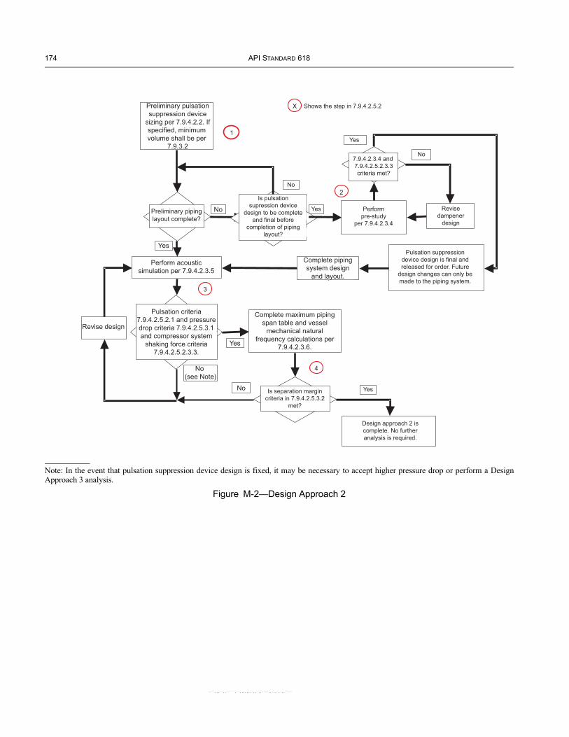
174 API STANDARD 618
Figure M-2—Design Approach 2
Shows the step in 7.9.2.6.2Preliminary PulsationSuppression DeviceSizing per 7.9.2.3. Ifspecified, minimump
7.9.1.4
PreliminaryPi i
Complete?
PerformPre-Study
per 7.9.2.4.4
Perform AcousticSimulation per 7.9.2.4.5
Yes
No
Pulsation Criteria7.9.2.6.2.1 and7 9 2 6 2 2pressure drop criteria
7.9.2.6.3.1 and CompressorSystem shaking force
criteria 7.9.2.6.2.3.2M t?
Complete Maximum PipingSpan Table and Vessel
Mechanical NaturalFrequency Calculations per
7.9.2.4.6Yes
ReviseDesign
No (seeNote)
1
2
3
4
X
ReviseDampener
Design
7.9.2.4.4 and7.9.2.6.2.3.2Criteria Met?
Yes
No
Is Separation MarginCriteria in 7.9.2.6.3.2
met?
No Yes
Design Approach 2 iscomplete. No furtheranalysis is required.
Is PulsationSuppression Device
design to be completeand final before
completion of pipinglayout?
Yes
No
Pulsation SuppressionDevice design is final andreleased for order. Future
design changes can only bemade to the piping system.
Complete pipingsystem design
and layout.
Preliminary pulsationsuppression device
sizing per 7.9.4.2.2. Ifspecified, minimum volume shall be per
7.9.3.2
Preliminary pipinglayout complete?
No
Yes
Perform acousticsimulation per 7.9.4.2.3.5
Pulsation criteria7.9.4.2.5.2.1 and pressuredrop criteria 7.9.4.2.5.3.1and compressor system
shaking force criteria7.9.4.2.5.2.3.3.
Revise design
No(see Note)
No
Yes
Complete maximum pipingspan table and vessel
mechanical naturalfrequency calculations per
7.9.4.2.3.6.
Complete pipingsystem design
and layout.
Is pulsationsupression device
design to be completeand final before
completion of pipinglayout?
Yes
No
Shows the step in 7.9.4.2.5.2
Yes
7.9.4.2.3.4 and 7.9.4.2.5.2.3.3criteria met?
No
Performpre-study
per 7.9.4.2.3.4
Revisedampener
design
Pulsation suppressiondevice design is final andreleased for order. Future
design changes can only bemade to the piping system.
YesIs separation margincriteria in 7.9.4.2.5.3.2
met?
Design approach 2 iscomplete. No furtheranalysis is required.
Note: In the event that pulsation suppression device design is fixed, it may be necessary to accept higher pressure drop or perform a Design Approach 3 analysis.
--``,,,``,,`````,``,,,,,,,`,,`,,-`-`,,`,,`,`,,`---

RECIPROCATING COMPRESSORS FOR PETROLEUM, CHEMICAL, AND GAS INDUSTRY SERVICES 175
--``,,,``,,`````,``,,,,,,,`,,`,,-`-`,,`,,`,`,,`---
Figure M-3—Design Approach 3
Preliminary pulsation suppression device sizing per7.9.4.2.2. If specified, minimum volume shall be per
7.9.3.2.
Shows the step in 7.9.4.2.5.2X
YesPerform acoustic
simulation per 7.9.4.2.3.5
Revisepulsation
suppressiondevice or
pipingsystemdesign
(see Note 3)
Pulsation criteria7.9.4.2.5.2.1 and 7.9.4.2.5.2.2.2
and pressure drop criteria7.9.4.2.5.3.1 met?
No
Yes
Preliminary pipinglayout complete?
No
No
Is the pulsationsuppression device
design to becompleted before
completion ofpreliminary piping
layout?
Yes
Yes
No7.9.4.2.3.4 and7.9.4.2.5.3.1ccriteria met?
Performpre-study per
7.9.4.2.3.4
Revisedampener
design
Completepipingsystemdesign
andlayout.
Pulsationsuppression
device design isfinal and releasedfor order. Future
design changes canonly be made to
the piping system.
No YesHas allowance to
exceed the pulsationcriteria in 7.9.4.2.5.2.1 or
7.9.4.2.5.2.2.3 beenagreed upon?(see Note 1)
No
Yes
Can the pulsationcriteria be met by
exceeding the pressure drop criteria
in 7.9.4.2.5.3.1c?(see Note 2)
No
Has allowance toexceed the pressure
drop criteria in7.9.4.2.5.3.1c been
given to enablecompliance with thepulsation criteria?
Yes
And
Step 3amechanical analysis
of compressor systemand piping system per
7.9.4.2.4.2
Revise pulsationsuppression
device and/orpiping system
and/or structuralsupport design(see Note 3)
NoYes
Piping systemseparation
margin criteria7.9.4.2.5.3.2 met?
YesNo
Piping systemshaking force
criteria7.9.4.2.5.2.3.3 met?
(see Note 4)
Or
Step 3bPerform forced mechanical response
analysis on piping system per 7.9.4.2.4.4
Revisedesign
Yes
No
Piping systemvibration criteria
7.9.4.2.5.2.4 met?
Yes No
Cyclic stress criteria7.9.4.2.5.2.5.1 met?
Yes
Design approach 3 is complete. Nofurther analysis is required.
No
Vibration and cyclic stresscriteria 7.9.4.2.5.2.5.1 met?
(see Note 5)
Step 3b1Perform forced mechanical response
analysis on compressor mechanical modelper 7.9.4.2.4.3
And And
Yes
Yes
No
No
Or
Compressorsystem
separationmargin driteria
7.9.4.2.5.3.2 met?
Compressorsystem shaking
force criteria7.9.4.2.5.2.3.3 met?
(see Note 4)
Revisepulsation
suppressiondevice and/orpiping system
and/orstructuralsupport
economically feasible to
; ,
,
,
7.9.4.2.4.4
Note 1—The default design philosophy ispressure pulsation control unless otherwisespecified. However, when evaluating theneed for possible modification to the pipingand/or pulsation suppression devices,consideration should be given to acoustical-shaking forces and the effect of pulsations oncompressor performance. Also, pulsationlevels (expressed as a percentage of linepressure) should not be used as the solecriterion for making modifications.
Note 2—For some applications that havevariable operating parameters such as speedor gas composition, it may not be technicallypossible or economically feasible tosimultaneously comply with the pulsation andthe pressure drop limitations for all operatingconditions. The purchaser and designershould mutually agree upon the mostappropriate compromise.
Note 3—When design revisions are complete,the flowchart indicates that the acoustic simulation is run again. In practice, if the revisions (for example, structural supportchanges) do not impact the acousticsimulation, then the previous simulation is stillvalid. In this case, the evaluation of the design change would begin with Step 3a; but,the designer is responsible for ensuring thatthe acoustic simulation is still valid. Also, notethat not all options for design revisions listed(for example, modifying the pulsationsuppression device) will be availabledepending upon decisions that have alreadybeen made.
Note 4—The requirement to analyze theshaking forces in Step 6 is waived if thecompressor vendor analyzes the pipingsystem vibration in Step 7 per 7.9.4.2.4.4. If theshaking forces are not analyzed, then “No” isselected and analysis proceeds to Step 7.
Note 5—The compressor vendor shall supplythe allowable vibration criteria for compressor components such as cylinders, distancepieces and crankcases. Due to the variabilityand complexity of compressor systems, it isnot possible to provide vibration criteria that,when met, eliminate the need to calculatestress.

--``,,,``,,`````,``,,,,,,,`,,`,,-`-`,,`,,`,`,,`---

Annex N(informative)
Guideline for Compressor Gas Piping Design and Preparation for anAcoustic Simulation Analysis
N.1 GeneralN.1.1 Any reciprocating compressor in conjunction with a piping system forms an interactive dynamic system that cannot be accurately analyzed as two separate systems. Therefore, it is virtually impossible for the pulsation system designer and the piping system designer to arrive at proposed designs on an independent basis that can be guaranteed to work in the final analysis and be cost effective.
N.1.2 This annex gives guidelines for the piping system designer which will help to minimize problems that can occur at the time of the acoustic simulation and it also outlines the information that must be available at the time of this interactive analysis. Communication between the piping system designer, the compressor vendor and the pulsation control system designer during the course of a project is important to minimize problems and develop the best overall compressor system installation. The key times of interaction are at the post order coordination meeting (see 9.1.3), early in the project, and during the interactive acoustic simulation/mechanical analysis.
N.1.3 The purchaser may elect to perform an in-house acoustic simulation, to use equipment vendor services or to use the services of a third party.
N.2 Acoustic Consideration in Piping DesignsN.2.1 The interaction of the compressor, pulsation devices and piping system produces potentially harmful pulsations when there is resonant interaction between the various elements in the system. The system designer can help to minimize this interaction by avoiding resonant lengths of pipe. When resonant lengths of pipe are used and the resonant frequency matches compressing frequency, one can expect major changes to the system as a result of the acoustic simulation analysis. The resonant length of various piping configurations is given in Equation N-1. It is recommended that lengths of these configurations be avoided in a ±10% band for the first four harmonics of compressor speed. The piping areas where this is most important are the sections of piping between the first major volume on the suction side and the first major volume on the discharge side. In piping areas outside major volumes, or those far enough away from the compressor(s) the potential for harmful pulsation buildup is considerably reduced.
N.2.2 For piping sections open at both ends or closed at both ends the length to be avoided can be calculated from the following:
LH30cnN--------= (N-1)
where
LH is the pipe length to be avoided in meters (feet);
C is the velocity of sound in gas in meters/second (feet/second);
n is the harmonic number (1, 2, 3 and 4);
N is the compressor speed in revolutions per minute.
Examples of this are lengths between major volumes, length of headers, etc.
N.2.3 For pipe sections open at one end and closed at the other end, the lengths to be avoided can be calculated from the following:
177--``,,,``,,`````,``,,,,,,,`,,`,,-`-`,,`,,`,`,,`---

178 API STANDARD 618
LQ
15CnN----------= (N-2)
where
LQ is the pipe length to be avoided in meters (feet);
C is the velocity of sound in gas in meters/second (feet/second);
n is the harmonic number (1, 2, 3 and 4);
N is the compressor speed in revolutions per minute.
Examples of this are relief valve lines and bypass lines.
Note: A pipe can be considered to have an open end if the diameter increases by a factor of 2 to 1 or more. Similarly, a pipe can be considered to have a closed end if the diameter is reduced by a factor of 2 to 1 or more.
N.2.4 The acoustic simulation should be carried out after a piping static stress analysis has demonstrated that the location and design of the piping restraints result in acceptable piping static stresses.
N.2.5 For variable speed compressors and/or those with varying gas composition and/or varying pressures and temperatures, the separation of resonances is more difficult to calculate and can only be handled properly with an acoustic simulation study.
N.3 Acoustic simulation studyN.3.1 The extent of the piping system to be analyzed by acoustic simulation techniques is usually defined as all associated piping systems to a point where piping changes will have only insignificant effects on the parts of the system under study and in determining the acoustic characteristics of the design. Typically, these requirements are satisfied by beginning the simulation with the inlet of a major process vessel or volume on the suction side of the compressor unit(s), continuing through all interstage systems (if any) and terminating the study at the outlet of a major process vessel or volume on the discharge side of the unit(s). Included are branch connections to or from this system, such as relief valve lines and bypass lines.
N.3.2 When major volumes do not exist or are very remote from the compressor, suitable piping lengths are included in the simulation, such that the pulsation levels are sufficiently low so as to minimize the potential of pulsation driven vibration problems.
N.4 Information requiredN.4.1 The acoustic simulation requires a considerable amount of information in order to be properly performed. The purchaser and the vendor should agree upon who is responsible for the development and compilation of the following information:
N.4.1.1 Data sheets showing all compressor operating conditions, analysis of all gases to be compressed, and all unloading steps.
N.4.1.2 Isometric drawings showing all lengths (between bends, valves, diameter changes, etc.) and line sizes and schedules for the complete piping system, including all branch lines and relief valve lines. If a mechanical study is included, the distance between the supports and the type of support and clamp used at each location must be shown on the isometrics. A detailed drawing of each type of support and clamp is required.
N.4.1.3 Piping and instrument diagrams (P&ID’s) are required to ensure that all piping and equipment that may effect the study are included.
N.4.1.4 Layout drawings are required to help determine the practicality of any proposed modifications. Reproducible drawings are useful since they can be marked up and copies can be included in the report.
N.4.1.5 Complete information must be supplied on all of the piping up to and including the first large volume in the suction, the interstage and the discharge piping. Every branch must be included up to a shutoff valve or a large volume.
N.4.1.6 Any orifice or other flow-resistive device must be shown and complete details provided.
N.4.1.7 Detailed drawings of each vessel, showing the location of all nozzles, the internal diameter and the length, as well as details of any vessel internals are required. Normal liquid levels and design pressure drops in these vessels must be shown.
--``,,,``,,`````,``,,,,,,,`,,`,,-`-`,,`,,`,`,,`---

RECIPROCATING COMPRESSORS FOR PETROLEUM, CHEMICAL, AND GAS INDUSTRY SERVICES 179
N.4.1.8 TEMA data sheets, or their equivalent, must be provided for all heat exchangers. The data sheets must show whether gas is through the tubes or in the shell; the number, length and gauge of tubes; whether the tubes are plain or finned; the number of passes; the I.D. of the shell; the gas temperature in and out; the gas pressure drop; and the dimensions of the header. A dimensional drawing is preferred.
N.4.1.9 If there are different gas routings, a complete description must be included to show the relative positions of all the valves for each routing. If different process gases are involved, the description must show which routings apply to which gases. Flow from/to any sidestream must be shown, including gas analysis, flow rate and direction.
N.4.1.10 If gas filters are used, the type of filter, internal diameter, length and element pressure drop must be supplied. A dimensional drawing is desirable.
N.4.1.11 When two or more compressors are connected to the same piping system, a clear description of how they will operate (such as unloading steps, speed differences, etc.) is required.
N.4.1.12 Detailed dimensional drawings on each suppressor showing the location of all nozzles, lengths, internal diameters and details on suppressor internals, if any.
N.4.1.13 The information in Table N.1 is required from the compressor vendor.
Table N-1—Compressor Data Required for Acoustic Simulation
Compressor Data Design Approach23a, 3b1, 3b2
Compressor dataHead end fixed clearance volumeHead end unloader volume(s)Crank end fixed clearance volumeCrank end unloader volume(s)
Casting drawingsCompressor cylinder (internal passage)Distance piece (inertia and stiffness)Crosshead guide (inertia and stiffness)
Assembled cylinder weight
XXXX
X
XXXX
XXXX
Support drawingsCylinder support drawingsCrosshead guide support drawingsDistance piece support drawingsPulsation suppressor support drawings
XXXX
Compressor Dynamic Valve Analysis Results XCrank angles between manifolded cylinders X
N.4.2 It is highly recommended that a piping system design representative who is familiar with the piping system be present at the acoustical simulation analysis, in order to make piping changes as the need arises.
--``,,,``,,`````,``,,,,,,,`,,`,,-`-`,,`,,`,`,,`---

--``,,,``,,`````,``,,,,,,,`,,`,,-`-`,,`,,`,`,,`---

--``,,,``,,`````,``,,,,,,,`,,`,,-`-`,,`,,`,`,,`---
Annex O(informative)
Guidelines for Sizing Low Pass Acoustic Filters
O.1 GeneralThe general configuration for an acoustic filter is shown in Figure O-1.
Figure O-1—Nonsymmetrical Filter
The lowest acoustic resonant frequency of the filter system, is referred to as Helmholtz frequency (fH). An accepted generalized equation for Helmholtz frequency is
fHc
2π------ μ
V1----- μ
V2-----+⎝ ⎠
⎛ ⎞12---
= (O-1)
where
fH is the Helmholtz frequency in Hertz;
c is the velocity of sound in gas in meters per second (feet per second);
V1 is the volume in cylinder bottle (chamber) in cubic meters (cubic feet);
V2 is the volume in filter bottle (chamber) in cubic meters (cubic feet);
μ is the acoustic conductivity in meters or feet.
where
μ ALc 0.6Dc+------------------------- A
L---= =
A is the internal cross-sectional area of choke in square meters (square feet);
Lc is the actual length of choke in meters (feet);
L is the acoustic length of choke in meters (feet);
Dc is the diameter of choke in meters (feet).
The filter cut-off frequency (fco), which is the frequency above which pulsation attenuation is achieved, is usually defined as follows
fco 2( )fH=
The acoustic filter can be either symmetrical or non-symmetrical. As shown in Figure O-1 and Equation 1, the non-symmetrical filter can have different volumes (lengths and diameters) and a different length of choke. For a symmetrical filter, the volumes are
181

182 API STANDARD 618
equal and the acoustic length of the choke L is equal to the length of each volume that is Lc = L. This is valid when Lc is much larger than Dc. This also means that the diameter of each volume is equal.
Substituting into Equation O-1, the Helmholtz frequency for a symmetrical filter becomes:
fH12
------- cπ--- Dc
LDB----------= (O-2)
where
DB = inside diameter of pulsation suppression devices in meters (feet).
O.2 GuidelinesThe following guidelines may be used for the preliminary sizing of acoustic filters.
O.2.1 SELECTION OF HELMHOLTZ FREQUENCY (FH)
The preferred Helmholtz frequency is:
fHs
85------=
where
s is the compressor speed in r/min.
Only when conditions are such that it is uneconomical, or physically impractical, should a higher Helmholtz frequency be considered, that is, only when pressure drop is very critical—as in the case of low suction pressure, or when space is limited by the compressor system layout. In that instance, a higher Helmholtz frequency may be chosen. Generally, the Helmholtz frequency should not be higher than
fHs
45------=
unless the acoustic simulation proves otherwise. For compressor speeds above 500 rpm, the Helmholtz frequency should not exceed:
fHs
85------=
O.2.2 RELATIONSHIPS OF FILTER ELEMENT DIAMETERS
For acoustic considerations, the diameter of the cylinder bottle (chamber) V1 should be equal to, or greater than, two times the diameter of the cylinder connection (flange). Larger ratios generally improve acoustic characteristics but may result in unacceptable mechanical characteristics. The final design ratio must be determined by both acoustic and mechanical analysis.
The diameter of the filter bottle (chamber) V2 should be equal to, or greater than, three times the diameter of the line piping.
O.2.3 RELATIONSHIP OF FILTER ELEMENT LENGTHS
The preferred filter system is with equal lengths of cylinder bottle (chamber), choke tube and filter bottle (chamber) that is L1 = LC = LZ. In cases where the physical restrains (piping layout) and the required sizes do not permit equal lengths, the next best alternative is with equal length of choke and filter (chamber) L1 ≠ LC = L2.
O.2.4 SIZING OF THE DIAMETER OF THE CHOKE TUBE (DC)
Unless otherwise specified, calculate the maximum allowable pressure drop per the applicable Equation 13 in 7.9.4.2.5.2.3.2. Using maximum allowable pressure drop and appropriate pressure drop relationship, calculate the minimum diameter choke tube which can be used considering all operating conditions expected.
O.2.5 ACOUSTIC SIMULATION OF THE PRELIMINARY DESIGN
These sizing guidelines cannot be used to determine the final dimensions of the filter elements without an acoustic simulation. Once the preliminary design of the filter is completed, an acoustic simulation must be performed to evaluate the unbalanced shaking forces within the components of the filter and the pulsation levels at the nozzles. Adjustments to the filter component dimensions are almost always made during the acoustic simulation.
--``,,,``,,`````,``,,,,,,,`,,`,,-`-`,,`,,`,`,,`---

Annex P(informative)
Piping and Pulsation Suppression Device Shaking Force Guidelines
P.1 GeneralShaking force guidelines provide an alternative evaluation tool to determine the need for forced mechanical response analysis. The foundation for deriving appropriate shaking force guidelines is knowledge of stiffness and acceptable vibration for the structure. Knowledge of the structure’s stiffness may be based on experience with similar structures, or based on calculation varying in precision from assuming minimum stiffness values to stiffness determined by detailed structural simulation. Similarly, knowledge of acceptable vibration may be experience based or determined by detailed structural modeling.
The adopted shaking force guidelines work in concert with the separation margin and the design vibration guidelines. The simplification to a non-resonant shaking force guideline requires simultaneous compliance with both the shaking force and separation margin guidelines.
Figure P-1 shows the piping non-resonant shaking force guideline versus a corresponding shaking force guideline accounting for resonance. The non-resonant shaking force guideline results in acceptable vibration when the separation margin guidelines are met. Meeting both the minimum natural frequency guideline and the non-resonant shaking force guideline ensures acceptable vibration for the first and second orders of compressor speed. Meeting both the 20% separation margin from natural frequencies and the non-resonant shaking force guideline will also ensure acceptable vibration at higher orders of compressor speed. Therefore, the piping non-resonant shaking force guideline applies when the separation margin guidelines are met. When the separation margin guidelines are not met, much lower piping shaking forces are required to ensure acceptable vibration.
Figure P-2 shows the pulsation suppression device non-resonant shaking force guideline versus a corresponding shaking force guideline accounting for typical resonance. As with the piping, the pulsation suppression device non-resonant shaking force guideline applies when the separation margin guidelines are met. When the separation margin guidelines are not met, much lower pulsation suppression device shaking forces are required to ensure acceptable vibration.
Figures P-1 and P-2 demonstrate the importance of meeting the separation margins when applying the non-resonant shaking force guidelines.
Figure P-1—Non–dimensional Piping Shaking Force Guidelines
183--``,,,``,,`````,``,,,,,,,`,,`,,-`-`,,`,,`,`,,`---

184 API STANDARD 618
Figure P-2—Non-dimensional Pulsation Suppression Device Shaking Force Guidelines
P.2 Orientation of Shaking Forces
P.2.1 PIPING ORIENTATION
The piping non-resonant shaking force guideline applies to shaking forces acting along the piping axis, as shown in Figure P-3, which cause non-resonant vibration. The piping non-resonant shaking force guideline cannot be applied when resonant vibration occurs in either the run containing the shaking force or in adjoining perpendicular piping.
Figure P-3—Shaking Forces along the Piping Axis
TransverseVibration
Axial Vibration
Axial Shaking Force,Axial Stiffness
P.2.2 CYLINDER MOUNTED PULSATION SUPPRESSION DEVICE ORIENTATION
The pulsation suppression device non-resonant shaking force guideline applies to shaking forces acting along the pulsation suppression device axis, as shown in Figure P-4, which cause non-resonant vibration.
--``,,,``,,`````,``,,,,,,,`,,`,,-`-`,,`
,,`,`,,`---
RECIPROCATING COMPRESSORS FOR PETROLEUM, CHEMICAL, AND GAS INDUSTRY SERVICES 185
--``,,,``,,`````,``,,,,,,,`,,`,,-`-`,,`,,`,`,,`---
Figure P-4—Shaking Forces along the Pulsation Suppression Device Axis
Shaking Force, Vibration
Shaking Force, Vibration
Cylinder
Suction PulsationSuppression Device
Discharge PulsationSuppression Device
Cylinder
Shaking Force, Vibration
Shaking Force, Vibration
P.3 Determination of Effective Static Stiffness
P.3.1 GENERAL
Suggested equations for effective stiffness of piping and pulsation suppression devices are provided in P.3.2 and P.3.3. In addition, meeting the minimum mechanical natural frequency guideline can be used to establish a required minimum effective static stiffness. Equations for minimum effective static stiffness of piping and pulsation suppression devices are also given below.
P.3.2 PIPING EFFECTIVE AND MINIMUM STATIC STIFFNESS
P.3.2.1 The effective axial stiffness of piping is usually determined by the axial stiffness of the supports as shown in Equation P-1.
. keff 0.66 n ks××= (P-1)
where
keff is the effective static stiffness along the piping where the shaking force acts in N/mm (lbf/in.);
0.66 is the dynamic design factor to account for reduced stiffness as resonance is approached (see Figure P-1);
n is the number of active axial supports (see P.2.1.1 when supports are not collinear with the pipe run where the shaking force is acting);
ks is the axial static support stiffness in N/mm (lbf/in.).
To satisfy the minimum natural frequency guideline (see clause 7.9.4.2.5.3.2), the active axial support stiffness must at least meet the minimum ks defined in Equation P-2. Equation P-2 satisfies the minimum required support stiffness for all practical piping configurations with maximum acceptable spans (see P.2.1.2 and P.2.1.3 regarding lumped masses and equipment).
minimum k s CKS A0.75 I0.25 fn,T 1.5 n 1– n⁄( )×××= (P-2)

186 API STANDARD 618
where
CKS is the constant dependent on support stiffness units (SI units: 1/130; USC units: 25);
A is the pipe cross-sectional metal area in mm2 (in.2);
= π/4 × (OD2 – ID2);
I is the pipe cross-sectional area moment of inertia in mm4 (in.4);
= π/64 × (OD4 – ID4);
OD is the pipe outer diameter in mm (in.);
ID is the pipe inner diameter in mm (in.);
fn,T is the minimum transverse natural frequency in Hz (see P 3.2.5);
n is the number of active supports (or n = 2 as a minimum, see P 3.2.7).
The actual value of ks should be determined and compared to the minimum ks requirement. When the actual ks is greater than minimum ks there is sufficient support stiffness to constrain higher shaking forces (up to the limit defined by Equation 10 in 7.9.4.2.5.2.3.2 and P.1). When the actual ks is lower than minimum ks, the minimum mechanical natural frequency separation margin guideline will not be met, and the possibility of operating on resonance within the first two orders of compressor speed must be considered.
The actual and minimum ks values should also be compared with the range of typical support stiffness values found in Note 2 of 7.9.4.2.5.2.3. The actual ks should fall within the range of the corresponding support type. When the minimum ks required exceeds the range of the corresponding support type, the actual ks must be carefully determined and either a sufficiently stiff type of structure must be used or the shaking force guideline must be reduced.
P.3.2.2 When supports are not collinear with the pipe run where the shaking force is acting (such as the middle section of U, Z or 3D bends), the perpendicular pipe sections clamped by the supports may be more flexible than the supports, and keff must correspondingly be reduced. Flexibility of the perpendicular pipe section should be considered when the support is offset greater than 25% of the maximum acceptable span length.
P.3.2.3 The calculation of minimum ks does not include lumped masses, but results in a conservative shaking force criteria when the separation margin minimum natural frequency guideline is satisfied. To ensure the separation margin criteria are satisfied, the support requirements of each lumped mass, such as valves, must additionally be provided.
P.3.2.4 The calculation of minimum ks is based on the minimum number of supports required to satisfy the minimum mechanical natural frequency guideline. When more than the minimum number of supports are present, the minimum ks can be reduced by the ratio of the minimum number required divided by the number of active supports.
P.3.2.5 The minimum transverse natural frequency (fn,T) required is dependent on the frequency of the shaking force. For example, to comply with the first part of the separation margin criteria, it is typically chosen as 2.4 times maximum rated speed. In higher speed compressors, this is not always practical to achieve, however Equation P-2 can still be used to determine the minimum support stiffness required for the given fn,T.
P.3.2.6 The minimum axial support stiffness requirements of vessels and equipment (such as secondary pulsation dampeners, separators, cooler sections and heat exchangers) should be determined directly from the equipment mass to meet the separation margin criteria.
P.3.2.7 The number of active supports include all axial restraints along the run containing the shaking force and restraints offset from the run less than 25% of the maximum acceptable span length.
P.3.2.8 Vessels and equipment may also be restraints. See examples in Figure P-5.
P.3.2.9 Pipe wall thickness is specified based on design pressure using applicable design codes and is not increased as a method to control vibration.
--``,,,``,,`````,``,,,,,,,`,,`,,-`-`,,`,,`,`,,`---

RECIPROCATING COMPRESSORS FOR PETROLEUM, CHEMICAL, AND GAS INDUSTRY SERVICES 187
Figure P-5—Examples of Shaking Force Restraints
L = Lspan / 4
n = 3
L = Lspan / 4
n = 3
L = Lspan / 4
n = 3
Shak
ing
Fo
rce
Shak
ing
Fo
rce
Shak
ing
Fo
rce
P.3.3 CYLINDER MOUNTED PULSATION SUPPRESSION DEVICE EFFECTIVE AND MINIMUM STATIC STIFFNESS
The effective axial stiffness of cylinder mounted pulsation suppression devices is the result of a complex interaction between many structures requiring detailed analysis or field measurement to determine. Expressed in the same form as the effective stiffness for piping yields Equation P-3.
keff 0.66 kt×= (P-3)
where
keff is the effective static stiffness along the pulsation suppression axis where the shaking force acts in N/mm (lbf/in.);
0.66 dynamic design factor to account for reduced stiffness as resonance is approached (see Figure P-2);
kt is the pulsation suppression device axial static support stiffness in N/mm (lbf/in.).
Noting that the cylinder assembly stiffness is a critical component of the pulsation suppression device stiffness, and considering reasonable supporting of typical cylinder assemblies, a minimum kt can be established based on the number of cylinders as shown in Equation P-4.
minimumkt kmin n× cyl=
where
kmin is the minimum pulsation suppression device axial static stiffness per cylinder nozzle (SI units: 50 × 103 N/mm; USC units: 3 × 10⁵ lbf/in.);
ncyl is the number of cylinders attached to pulsation suppression device.
CAUTION: Long cylinder nozzles, double compartment and small cross-section distance pieces may not provide the minimum axial stiffness.
Also, on higher speed units, larger and higher pressure cylinders may require greater than the minimum axial stiffness to meet the minimum natural frequency guideline. Cylinders heavier than shown in Table P-1 may require additional supporting.
Table P-1—Cylinder Assembly Weights Possibly Requiring Strengthening
Maximum Compressor Speed (rpm) 300 600 900 1000 1200 1500Cylinder Assembly Weight (N) 89000 22000 9800 8000 5500 3500Cylinder Assembly Weight (lbf) 20000 5000 2200 1800 1250 800
The maximum cylinder assembly weight for compressor speeds not shown in the Table P-1 can be obtained using Equation P-5.
. Wcyl Cc S2⁄=--``,,,``,,`````,``,,,,,,,`,,`,,-`-`,,`,,`,`,,`---

188 API STANDARD 618
--``,,,``,,`````,``,,,,,,,`,,`,,-`-`,,`,,`,`,,`---
where
Wcyl is the maximum cylinder assembly weight in N (lbf);
Cc is the constant dependent on weight and stiffness units (SI units: 8.0 × 10⁹; USC units: 1.8 × 10⁹);
S is the compressor rotational speed in r/min.
P.4 Evaluation of Shaking ForcesMaking modifications to reduce predicted shaking forces is referred to as shaking force control (see API RP 688 for a complete discussion of the various control methods). As a minimum, shaking force control is required for all cylinder mounted pulsation suppression devices. When the purchaser agrees, shaking force control may be used in place of piping pressure pulsation guidelines.
The first step in the shaking force control method is to determine the shaking force guidelines using the equations and methods shown in 7.9.4.2.5.3 and Annex P. Then, the predicted shaking forces are compared to the shaking force and separation margin guidelines. When predicted shaking forces do not meet these guidelines, then one or more of the following actions must be taken to obtain acceptable results:
—modify system acoustics to reduce predicted shaking forces;—modify support structure to meet separation margin guidelines;—perform forced mechanical response analysis and satisfy vibration guideline.
Combinations of the above options are often employed in an iterative fashion to arrive at acceptable predicted shaking forces for the entire system.

--``,,,``,,`````,``,,,,,,,`,,`,,-`-`,,`,,`,`,,`---
Annex Q(informative)
Compressor Components—Compliance with NACE MR0175
189

190 API STANDARD 618
Figure Q-1—Material Guidelines for Compressor Components—Compliance with NACE MR0175
Spac
er
Oil
wip
erpa
ckin
gO
il sl
inge
r
Inte
rmed
iate
par
titio
npa
ckin
gSp
acer
Pres
sure
pack
ing
O-r
ing
type
val
ve c
over
Port
or p
lug
type
unl
oade
r
Fing
er ty
pe v
alve
unl
oade
r
Cle
aran
cepo
cket
unlo
ader
Not
es:
1. A
ll p
arts
sho
wn
not s
ecti
oned
are
req
uire
d b
y 6.
15.1
.11
to b
e N
AC
E M
RO17
5 m
ater
ial.
All
par
ts s
how
n se
ctio
ned
are
not
req
uire
d to
be
NA
CE
mat
eria
ls.
2. A
pp
lyin
g N
AC
E ex
pos
ure
gui
del
ines
allo
w th
e us
e of
non
-NA
CE
bol
ting
mat
eria
ls fo
r ex
tern
al fa
sten
ers
on th
e cy
lind
er a
nd in
tern
al fa
sten
ers
wit
hin
the
dis
tanc
e p
iece
s.3.
See
Fig
ure
J-1
for r
ecip
roca
ting
com
pre
ssor
nom
encl
atur
e.
--``,,,``,,`````,``
,,,,,,,`,,`,,-`-`,,`,,`,`,,`---
1
Date of Errata Issue: November 2009 Affected Publication: API Standard 618, Reciprocating Compressors for Petroleum, Chemical, and Gas Industry Services, Fifth Edition, December 2007
ERRATA 1
This errata corrects editorial errors in the fifth edition of API 618. Page 139, Annex F, F.1, insert the following VDDR forms:
--``,,,``,,`````,``,,,,,,,`,,`,,-`-`,,`,,`,`,,`---

JOB NO. ITEM NO.
PURCHASE ORDER NO. DATE
REQUISITION NO. DATE
INQUIRY NO. DATE
PAGE OF BY
FOR REVISION
SITE UNIT
SERVICE NO. REQUIRED
Proposal a Bidder shall furnish copies of data for all items indicated by an X.
Review b Vendor shall furnish copies and transparencies of drawings and data indicated.
Final c Vendor shall furnish copies and transparencies of drawings and data indicated.
Vendor shall furnish operating and maintenance manuals.
Final-Received from vendor
Final-Due from vendor c
Review-Returned to vendor
Review-Received from vendor
Review-Due from vendor c
a Proposal drawings and data do not have to be certified or as-built. Typical data shall be clearly identified as such.
b Purchaser shall indicate in this column the timeframe for submission of materials using the nomenclature given at the end of this form.
c Bidder shall complete these two columns to reflect their actual distribution schedule and include this form with their proposal.
1 2
DISTRIBUTION
RECORD
DESCRIPTION
TYPICALVENDOR DRAWING ANDDATA REQUIREMENTS
--``,,,``,,`````,``,,,,,,,`,,`,,-`-`,,`,,`,`,,`---

JOB NO. ITEM NO.
PAGE OF BY
DATE REVISION
Proposal a Bidder shall furnish copies of data for all items indicated by an X.
Review b Vendor shall furnish copies and transparencies of drawings and data indicated.
Final c Vendor shall furnish copies and transparencies of drawings and data indicated.
Vendor shall furnish operating and maintenance manuals.
Final-Receive from vendor
Final-Due from vendor c
Review-Returned to vendor
Review-Received from vendor
Review-Due from vendor c
a Proposal drawings and data do not have to be certified or as-built. Typical data shall be clearly identified as such.
b Purchaser shall indicate in this column the timeframe for submission of materials using the nomenclature given at the end of this form.
c Bidder shall complete these two columns to reflect their actual distribution schedule and include this form with their proposal.
Notes:1. Send all drawings and data to
2. All drawings and data shall show project, purchase order, and item numbers in addition to the plant location and unit.
In addition to the copies specified above, one set of the drawings/instructions necessary for field installation must be
forwarded with the shipment.
Nomenclature:
S: number of weeks before shipment.
F: number of weeks after firm order.
D: number of weeks after receipt of approved drawings.
Vendor
Date Vendor Reference
Signature
(Signature acknowledges receipt of all instructions)
RECORD
DESCRIPTION
2 2
DISTRIBUTION
TYPICALVENDOR DRAWING AND
DATA REQUIREMENTS
--``,,,``,,`````,``,,,,,,,`,,`,,-`-`,,`,,`,`,,`---

--``,,,``,,`````,``,,,,,,,`,,`,,-`-`,,`,,`,`,,`---

Invoice To (❏ Check here if same as “Ship To”)
Name:
Title:
Company:
Department:
Address:
City: State/Province:
Zip/Postal Code: Country:
Telephone:
Fax:
E-Mail:
❏ Payment Enclosed ❏ P.O. No. (Enclose Copy)
❏ Charge My IHS Account No.
❏ VISA ❏ MasterCard ❏ American Express ❏ Diners Club ❏ Discover
Credit Card No.:
Print Name (As It Appears on Card):
Expiration Date:
Signature:
Quantity Product Number Title Total
Subtotal
Applicable Sales Tax (see below)
Rush Shipping Fee (see below)
Shipping and Handling (see below)
Total (in U.S. Dollars)
★ To be placed on Standing Order for future editions of this publication,place a check mark in the SO column and sign here:
Pricing and availability subject to change without notice.
Date:
SO★ Unit Price
❏ API Member (Check if Yes)
Ship To (UPS will not deliver to a P.O. Box)
Name:
Title:
Company:
Department:
Address:
City: State/Province:
Zip/Postal Code: Country:
Telephone:
Fax:
E-Mail:
Mail Orders – Payment by check or money order in U.S. dollars is required except for established accounts. State and local taxes, $10 processing fee, and 5% shipping mustbe added. Send mail orders to: API Publications, IHS, 15 Inverness Way East, c/o Retail Sales, Englewood, CO 80112-5776, USA.Purchase Orders – Purchase orders are accepted from established accounts. Invoice will include actual freight cost, a $10 processing fee, plus state and local taxes.Telephone Orders – If ordering by telephone, a $10 processing fee and actual freight costs will be added to the order.Sales Tax – All U.S. purchases must include applicable state and local sales tax. Customers claiming tax-exempt status must provide IHS with a copy of their exemptioncertificate.Shipping (U.S. Orders) – Orders shipped within the U.S. are sent via traceable means. Most orders are shipped the same day. Subscription updates are sent by First-ClassMail. Other options, including next-day service, air service, and fax transmission are available at additional cost. Call 1-800-854-7179 for more information.Shipping (International Orders) – Standard international shipping is by air express courier service. Subscription updates are sent by World Mail. Normal delivery is 3-4 daysfrom shipping date.Rush Shipping Fee – Next Day Delivery orders charge is $20 in addition to the carrier charges. Next Day Delivery orders must be placed by 2:00 p.m. MST to ensure overnightdelivery.Returns – All returns must be pre-approved by calling the IHS Customer Service Department at 1-800-624-3974 for information and assistance. There may be a 15% restock-ing fee. Special order items, electronic documents, and age-dated materials are non-returnable.
Effective January 1, 2007.API Members receive a 30% discount where applicable.The member discount does not apply to purchases made for the purpose of resale or for incorporation into commercial products, training courses, workshops, or othercommercial enterprises.
Available through IHS:Phone Orders: 1-800-854-7179 (Toll-free in the U.S. and Canada)
303-397-7956 (Local and International)Fax Orders: 303-397-2740Online Orders: global.ihs.com
2007 PublicationsOrder Form
--``,,,``,,`````,``,,,,,,,`,,`,,-`-`,,`,,`,`,,`---

There’s more where thiscame from.
The American Petroleum Institute provides additional resources and programs to the oil and natural gas industry which are based on API® Standards. For moreinformation, contact:
• API Monogram® Licensing Program Phone: 202-962-4791Fax: 202-682-8070
• American Petroleum Institute Quality Registrar Phone: 202-962-4791(APIQR®) Fax: 202-682-8070
• API Spec Q1® Registration Phone: 202-962-4791Fax: 202-682-8070
• API Perforator Design Registration Phone: 202-962-4791Fax: 202-682-8070
• API ISO/TS 29001 Registration Phone: 202-962-4791Fax: 202-682-8070
• API Training Provider Certification Program Phone: 202-682-8490Fax: 202-682-8070
• Individual Certification Programs Phone: 202-682-8064Fax: 202-682-8348
• Engine Oil Licensing and Certification System (EOLCS) Phone: 202-682-8516Fax: 202-962-4739
• API PetroTEAM™ (Training, Education and Meetings) Phone: 202-682-8195Fax: 202-682-8222
Check out the API Publications, Programs, and Services Catalog online at www.api.org.
Helping You Get The Job Done Right.®--``,,,``,,`````,``,,,,,,,`,,`,,-`-`,,`,,`,`,,`---

11/07--``,,,``,,`````,``,,,,,,,`,,`,,-`-`,,`,,`,`,,`---

Product No. C61805
--``,,,``,,`````,``,,,,,,,`,,`,,-`-`,,`,,`,`,,`---