rbx series round baler - Machinery & Parts Export, LLC PM-13750.pdf · rbx series round baler...
36
rbx series round baler FEATURING • Safety • Service Inspections • Baler Monitor Functions • Baler Operation • Maintenance • Troubleshooting • Updates and Kits
Transcript of rbx series round baler - Machinery & Parts Export, LLC PM-13750.pdf · rbx series round baler...
rbx series round baler
FEATURING• Safety• Service Inspections• Baler Monitor Functions• Baler Operation• Maintenance• Troubleshooting• Updates and Kits
GENERAL INFORMATION
CONTENTS
Safety .................................................... 3-4
Service Inspections ................................. 5-6
Baler Monitor Functions ........................ 7-11
Baler Operation.................................. 12-19
Maintenance ...................................... 20-26
Troubleshooting .................................. 27-28
Parts Kits/Accessories/Assemblies ...... 29-35
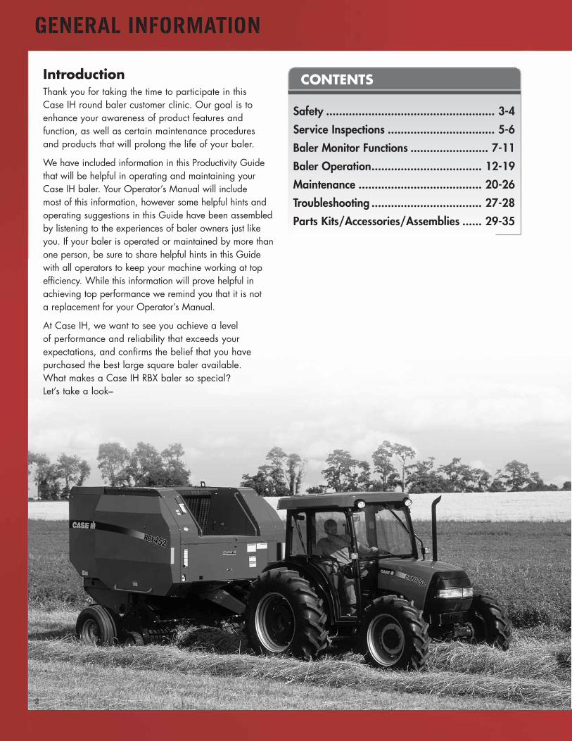
IntroductionThank you for taking the time to participate in thisCase IH round baler customer clinic. Our goal is toenhance your awareness of product features andfunction, as well as certain maintenance proceduresand products that will prolong the life of your baler.
We have included information in this Productivity Guidethat will be helpful in operating and maintaining yourCase IH baler. Your Operator’s Manual will includemost of this information, however some helpful hints andoperating suggestions in this Guide have been assembledby listening to the experiences of baler owners just likeyou. If your baler is operated or maintained by more thanone person, be sure to share helpful hints in this Guidewith all operators to keep your machine working at topefficiency. While this information will prove helpful inachieving top performance we remind you that it is nota replacement for your Operator’s Manual.
At Case IH, we want to see you achieve a levelof performance and reliability that exceeds yourexpectations, and confirms the belief that you havepurchased the best large square baler available.What makes a Case IH RBX baler so special?Let’s take a look–
2
SAFETY
3
We value our customers, and hope that each balingseason is safe and productive. Sometimes, in the rush tobeat the weather, start chores, or avoid missing the firstinning of the softball game, safety vigilance fails—andthe risk of an accident soars. Never attempt to save amoment by compromising safety—the result can cost moretime than ever was saved—and sometimes the cost maybe immeasurable. The Operator’s Manual contains acomprehensive list of safety rules for your RBX Seriesbaler. Please take a few moments to review the entirelist. We’ve listed some of the most important here.
General Safety Rules➤ Read the Operator’s Manual thoroughly before
starting, operating, servicing or carrying out anyother operation on the machine. The time investedin reviewing the manual will pay off in terms of timesaved later.
➤ Read all the safety decals on the machine and followthe instructions. Immediately replace any decals thatare missing or damaged.
➤ The baler should be operated only by responsibleindividuals, who are familiar with the machine.
➤ Avoid fire hazards by keeping the baler clean. Inspectthe unit daily for signs of hydraulic leaks, and haveleaks repaired before further use.
➤ A fire extinguisher should be mounted on the baler,easily accessible from the ground and away frommoving parts and areas where debris is likely toaccumulate. The presence of hydraulic and lubricatingoil dictate that an ABC extinguisher is the best choice.
➤ Though not directly related to baler operation—aword of caution about handling large bales. Everyyear, individuals are injured when using incorrectmethods of handling that do not completely restrainand control the weight of large bales. Use thecorrect spear or grapple equipment to handle bales.Refer to loader or bale carrier Operator Manuals forcorrect bale handling methods.
Baler Hookup, Transport andField Operation➤ Before connecting the baler to the tractor, be sure the
tractor meets minimum horsepower requirements andis ballasted to control the weight of the baler,especially when operating in hilly terrain.
➤ Do not enter the area between the tractor wheels andthe baler when the tractor engine is running.
➤ Be sure the tractor drawbar capacity is sufficient forthe baler tongue weight. The hitch pin must be securelycross pinned, and the safety chain properly connectedto the tractor before road transport. Check warninglights before entering a public roadway.
➤ When transporting the baler on a public road, fully raisethe pickup, and engage the flywheel brake. Raise thebale chute to close the bale chamber.
➤ Always use SMV sign, flashing warning lights, and turnsignals when transporting the machine on public roads.
➤ Maintain a safe speed when transporting andmaneuvering the baler in traffic. Be constantly awareof the size and weight of the towed baler. Allow forthe added weight of bales that may be in the baler.
➤ Do not work around the baler wearing loose clothingthat could get caught in the moving parts.
➤ Prior to operating the baler, assure that all guardsand covers provided are properly installed, includingPTO shaft shielding.
➤ Never allow anyone to ride on the baler or thetractor. Keep the children away from and off thebaler at all times.
➤ Prior to engaging the PTO, always make sure thereare no bystanders nearby. Sound a warning with thetractor horn as an added precaution.
➤ Always operate the baler at a safe speed, especiallywhen on uneven ground or inclines. Use particularcare when turning on hillsides or near embankments.
➤ Always make sure that the area behind the machineis clear before manually ejecting the bale.
4
SAFETY
BASIC CONFIGURATION SPECIFICATIONS
The RBX series of Round Balers is offered in two basicbale widths of 3.9' (nominal 4') and 5.1' (nominal 5').Minimum bale diameter is 2.5' on RBX443, and 3' onall other models. Maximum nominal bale size, in feet,for all models is 4 X 4 (RBX443); 4 X 5 (RBX453);4 X 6 (RBX463); 5 X 5 (RBX553); and 5 X 6 (RBX563).
Four standard pickup sizes include 5', 6.4', 7'and 7.8'. Pickup style and width are matched to balersize and specialty function for optimum crop movementfrom stubble to the baler. Standard and wide widthchoices are available for RBX463 and RBX563.
RBX453 is available in both Silage and Rotor-cutterSilage models, with structural modifications andendless belts to handle the added weight of high-moisture crop, as well as special roll and belt featuresto self-clean the unit and prevent accumulation ofsticky crop residue.
Chevron pattern belts and steel rolls aggressivelymove and tumble crop for quick and effortless core
formation. A stuffer pickup is available on all modelsexcept the RBX553.
All RBX models are equipped for twine wrapping.The RBX443 uses a single arm, double twineelectrically actuated system. The Electric-ControlledTwine Wrap System is available for twine-onlywrapping on RBX453 Silage, RBX453 Rotor-cutterSilage, RBX463 and RBX563; with in-cab controlof twine application using the dual twin arm system.The Electric-Controlled Twine wrap console alsoincludes bale shape and size indicators, and afull bale alarm.
The Electronic Auto-Controlled Twine/Mesh WrapSystem offers programmable twine and net placement.This automated system is available on all modelsexcept RBX443. The net wrapping system can be usedwith standard-width net that covers the outer balesurface, in addition to wider net that wraps aroundthe outer edges of the bale for improved appearance,weather resistance and handling characteristics.
Baler Hookup, Transport andField Operation (cont.)➤ Keep hands, feet and/or garments away from
moving parts. ALWAYS DISENGAGE THE PTO ANDSTOP THE TRACTOR ENGINE before attemptingservice, adjustments or clearing the baler of crop ordebris. Do not dismount the tractor until all machinerotation has stopped. Remove the ignition key fromthe tractor when leaving the equipment unattended.
➤ If the baler is equipped with a rotor-cutter, use specialcare when working in the area near the cutter knives.Lower the knives out of the feeder area using thetractor hydraulic valve prior to servicing or removingcrop from the feeder.
Machine Maintenance➤ When adjusting, cleaning, lubricating or performing
repairs, the baler must be completely stopped.Disengage the PTO, stop the tractor engine.
➤ If the gate is opened for service operations, closethe gate lock valve before entering the area underor near the gate.
➤ Always block the baler wheels and set the tractorparking brake before working on or under the machine.
➤ When working on the hydraulic system, alwaysensure that the system is not under pressure beforedisconnecting pipes and/or hoses.
➤ When servicing belts or rollers, tension must beremoved from the belts. Use the procedure detailedin the Operator’s Manual to relieve belt tension.
➤ Oil escaping under pressure can be injected into theskin and cause serious injury. When searching for oilleaks, wear safety glasses and use a piece of woodor cardboard to locate high pressure leaks. NEVERuse your hands to detect an oil leak.
➤ When servicing or repairs are complete, make surethat all guards are in place.
SERVICE INSPECTIONS
5
Take Full Advantage of its Capabilities
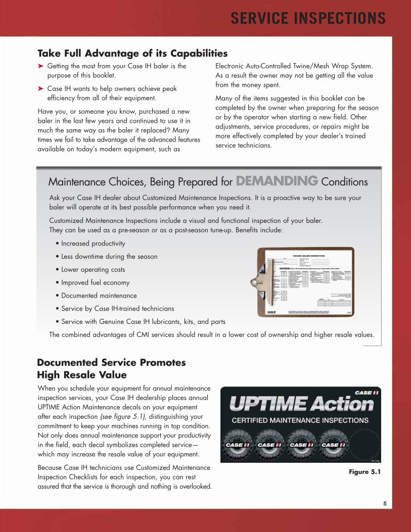
When you schedule your equipment for annual maintenanceinspection services, your Case IH dealership places annualUPTIME Action Maintenance decals on your equipmentafter each inspection (see figure 5.1), distinguishing yourcommitment to keep your machines running in top condition.Not only does annual maintenance support your productivityin the field, each decal symbolizes completed service—which may increase the resale value of your equipment.
Because Case IH technicians use Customized MaintenanceInspection Checklists for each inspection, you can restassured that the service is thorough and nothing is overlooked.
Maintenance Choices, Being Prepared for DEMANDING ConditionsAsk your Case IH dealer about Customized Maintenance Inspections. It is a proactive way to be sure yourbaler will operate at its best possible performance when you need it.
Customized Maintenance Inspections include a visual and functional inspection of your baler.They can be used as a pre-season or as a post-season tune-up. Benefits include:
• Increased productivity
• Less downtime during the season
• Lower operating costs
• Improved fuel economy
• Documented maintenance
• Service by Case IH-trained technicians
• Service with Genuine Case IH lubricants, kits, and parts
The combined advantages of CMI services should result in a lower cost of ownership and higher resale values.
Documented Service PromotesHigh Resale Value
Figure 5.1
➤ Getting the most from your Case IH baler is thepurpose of this booklet.
➤ Case IH wants to help owners achieve peakefficiency from all of their equipment.
Have you, or someone you know, purchased a newbaler in the last few years and continued to use it inmuch the same way as the baler it replaced? Manytimes we fail to take advantage of the advanced featuresavailable on today’s modern equipment, such as
Electronic Auto-Controlled Twine/Mesh Wrap System.As a result the owner may not be getting all the valuefrom the money spent.
Many of the items suggested in this booklet can becompleted by the owner when preparing for the seasonor by the operator when starting a new field. Otheradjustments, service procedures, or repairs might bemore effectively completed by your dealer’s trainedservice technicians.
6
SERVICE INSPECTIONS
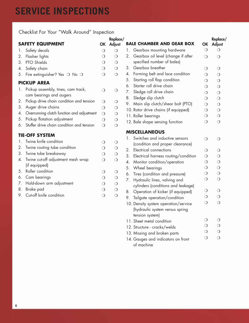
SAFETY EQUIPMENT1. Safety decals2. Flasher lights3. PTO Shields4. Safety chain5. Fire extinguisher? Yes ❍ No ❍
PICKUP AREA1. Pickup assembly, tines, cam track,
cam bearings and augers2. Pickup drive chain condition and tension3. Auger drive chains4. Overrunning clutch function and adjustment5. Pickup flotation adjustment6. Stuffer drive chain condition and tension
TIE-OFF SYSTEM1. Twine knife condition2. Twine routing tube condition3. Twine tube breakaway4. Twine cut-off adjustment mesh wrap
(if equipped)5. Roller condition6. Cam bearings7. Hold-down arm adjustment8. Brake pad9. Cut-off knife condition
BALE CHAMBER AND GEAR BOX1. Gearbox mounting hardware2. Gearbox oil level (change if after
specified number of bales)3. Gearbox breather4. Forming belt and lace condition5. Starting roll flap condition6. Starter roll drive chain7. Sledge roll drive chain8. Sledge slip clutch9. Main slip clutch/shear bolt (PTO)10. Rotor drive chains (if equipped)11. Roller bearings12. Bale shape sensing function
MISCELLANEOUS1. Switches and inductive sensors
(condition and proper clearance)2. Electrical connections3. Electrical harness routing/condition4. Monitor condition/operation5. Wheel bearings6. Tires (condition and pressure)7. Hydraulic lines, valving and
cylinders (conditions and leakage)8. Operation of kicker (if equipped)9. Tailgate operation/condition10. Density system operation/service
(hydraulic system versus springtension system)
11. Sheet metal condition12. Structure - cracks/welds13. Missing and broken parts14. Gauges and indicators on front
of machine
Replace/OK Adjust
❍ ❍
❍ ❍
❍ ❍
❍ ❍
❍ ❍
❍ ❍
❍ ❍
❍ ❍
❍ ❍
❍ ❍
❍ ❍
❍ ❍
❍ ❍
❍ ❍
❍ ❍
❍ ❍
❍ ❍
❍ ❍
❍ ❍
❍ ❍
Replace/OK Adjust
❍ ❍
❍ ❍
❍ ❍
❍ ❍
❍ ❍
❍ ❍
❍ ❍
❍ ❍
❍ ❍
❍ ❍
❍ ❍
❍ ❍
❍ ❍
❍ ❍
❍ ❍
❍ ❍
❍ ❍
❍ ❍
❍ ❍
❍ ❍
❍ ❍
❍ ❍
❍ ❍
❍ ❍
❍ ❍
❍ ❍
Checklist For Your “Walk Around” Inspection

BALER MONITOR FUNCTIONS
7
Manually retracts twine or net actuator
Manually extends twine or net actuator
Display or change pre-set bale diameter
Display or change number of wrapsof twine or netIncrease bale diameter or numberof wraps valuesDecrease bale diameter or numberof wraps values
Figure 7.1
Electronic Auto-Controlled Twine/Mesh Wrap SystemThe Electronic Auto-Controlled Twine/Mesh Wrap System baler control monitor gives the operator in-cab controlor display of bale size, bale shape, net or twine wrap, number of wraps, wrap pattern, and crop cutter knives.Electronic Auto-Controlled Twine/Mesh Wrap System is required to control net wrapping on the RBX series balers.
The operation of the monitor divides controls into 5 basic areas of function. These functions are illustrated in termsof touchpad control grouping, identification and control action explanation (see figure 7.1).
Baler Monitor
Turns the Net-Twine Wrapper system on and off
Toggles between system Setup and Diagnostic modes
Toggles between Automatic and Manualoperation of the Wrap system
Toggles between wrapping bales withNet and Twine
Manually starts wrap cycle
Clears daily bale counts, turn off audible alarmand error message displays
Toggles between Daily and Total bale counts
8
BALER MONITOR FUNCTIONS
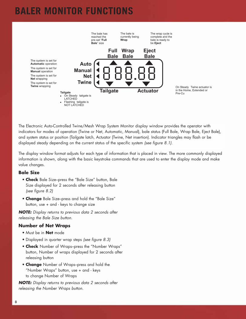
The Electronic Auto-Controlled Twine/Mesh Wrap System Monitor display window provides the operator withindicators for modes of operation (Twine or Net, Automatic, Manual), bale status (Full Bale, Wrap Bale, Eject Bale),and system status or position (Tailgate latch, Actuator (Twine, Net insertion). Indicator triangles may flash or bedisplayed steady depending on the current status of the specific system (see figure 8.1).
The display window format adjusts for each type of information that is placed in view. The more commonly displayedinformation is shown, along with the basic keystroke commands that are used to enter the display mode and makevalue changes.
Bale Size• Check Bale Size–press the “Bale Size” button, Bale
Size displayed for 2 seconds after releasing button(see figure 8.2)
• Change Bale Size–press and hold the “Bale Size”button, use + and - keys to change size
NOTE: Display returns to previous data 2 seconds afterreleasing the Bale Size button.
Number of Net Wraps• Must be in Net mode
• Displayed in quarter wrap steps (see figure 8.3)
• Check Number of Wraps–press the “Number Wraps”button, Number of wraps displayed for 2 seconds afterreleasing button
• Change Number of Wraps–press and hold the“Number Wraps” button, use + and - keysto change Number of Wraps
NOTE: Display returns to previous data 2 seconds afterreleasing the Number Wraps button.
9
BALER MONITOR FUNCTIONS
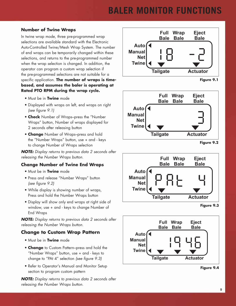
Number of Twine WrapsIn twine wrap mode, three pre-programmed wrapselections are available standard with the ElectronicAuto-Controlled Twine/Mesh Wrap System. The numberof end wraps can be temporarily changed within theseselections, and returns to the pre-programmed numberwhen the wrap selection is changed. In addition, theoperator can program a custom wrap selection ifthe pre-programmed selections are not suitable for aspecific application. The number of wraps is time-based, and assumes the baler is operating atRated PTO RPM during the wrap cycle.
• Must be in Twine mode
• Displayed with wraps on left, end wraps on right(see figure 9.1)
• Check Number of Wraps–press the “NumberWraps” button, Number of wraps displayed for2 seconds after releasing button
• Change Number of Wraps–press and holdthe “Number Wraps” button, use + and - keysto change Number of Wraps selection
NOTE: Display returns to previous data 2 seconds afterreleasing the Number Wraps button.
Change Number of Twine End Wraps• Must be in Twine mode
• Press and release “Number Wraps” button(see figure 9.2)
• While display is showing number of wraps,Press and hold the Number Wraps button
• Display will show only end wraps at right side ofwindow, use + and - keys to change Number ofEnd Wraps
NOTE: Display returns to previous data 2 seconds afterreleasing the Number Wraps button.
Change to Custom Wrap Pattern
• Must be in Twine mode
• Change to Custom Pattern–press and hold the“Number Wraps” button, use + and - keys tochange to “PAt 4” selection (see figure 9.3)
• Refer to Operator's Manual and Monitor Setupsection to program custom pattern
NOTE: Display returns to previous data 2 seconds afterreleasing the Number Wraps button.
Figure 9.1
Figure 9.2
Figure 9.3
Figure 9.4
BALER MONITOR FUNCTIONS
10
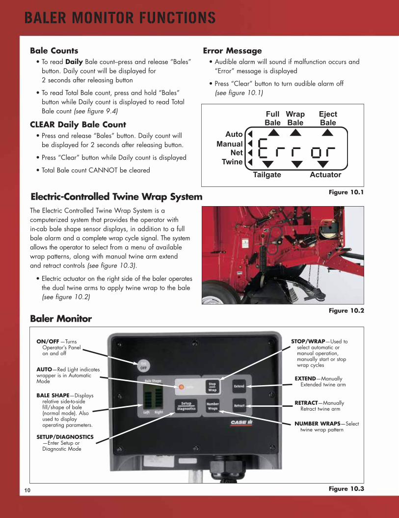
Bale Counts• To read Daily Bale count–press and release “Bales”
button. Daily count will be displayed for2 seconds after releasing button
• To read Total Bale count, press and hold “Bales”button while Daily count is displayed to read TotalBale count (see figure 9.4)
CLEAR Daily Bale Count• Press and release “Bales” button. Daily count will
be displayed for 2 seconds after releasing button.
• Press “Clear” button while Daily count is displayed
• Total Bale count CANNOT be cleared
Error Message• Audible alarm will sound if malfunction occurs and
“Error” message is displayed
• Press “Clear” button to turn audible alarm off(see figure 10.1)
Figure 10.1
The Electric Controlled Twine Wrap System is acomputerized system that provides the operator within-cab bale shape sensor displays, in addition to a fullbale alarm and a complete wrap cycle signal. The systemallows the operator to select from a menu of availablewrap patterns, along with manual twine arm extendand retract controls (see figure 10.3).
• Electric actuator on the right side of the baler operatesthe dual twine arms to apply twine wrap to the bale(see figure 10.2)
Figure 10.2
Electric-Controlled Twine Wrap System
Figure 10.3
Baler Monitor
EXTEND—ManuallyExtended twine arm
RETRACT—ManuallyRetract twine arm
NUMBER WRAPS—Selecttwine wrap pattern
SETUP/DIAGNOSTICS—Enter Setup orDiagnostic Mode
BALE SHAPE—Displaysrelative side-to-sidefill/shape of bale(normal mode). Alsoused to displayoperating parameters.
ON/OFF —TurnsOperator’s Panelon and off
STOP/WRAP—Used toselect automatic ormanual operation,manually start or stopwrap cycles
AUTO—Red Light indicateswrapper is in AutomaticMode
11
BALER MONITOR FUNCTIONS
FullBale
Figure 11.2
Figure 11.1
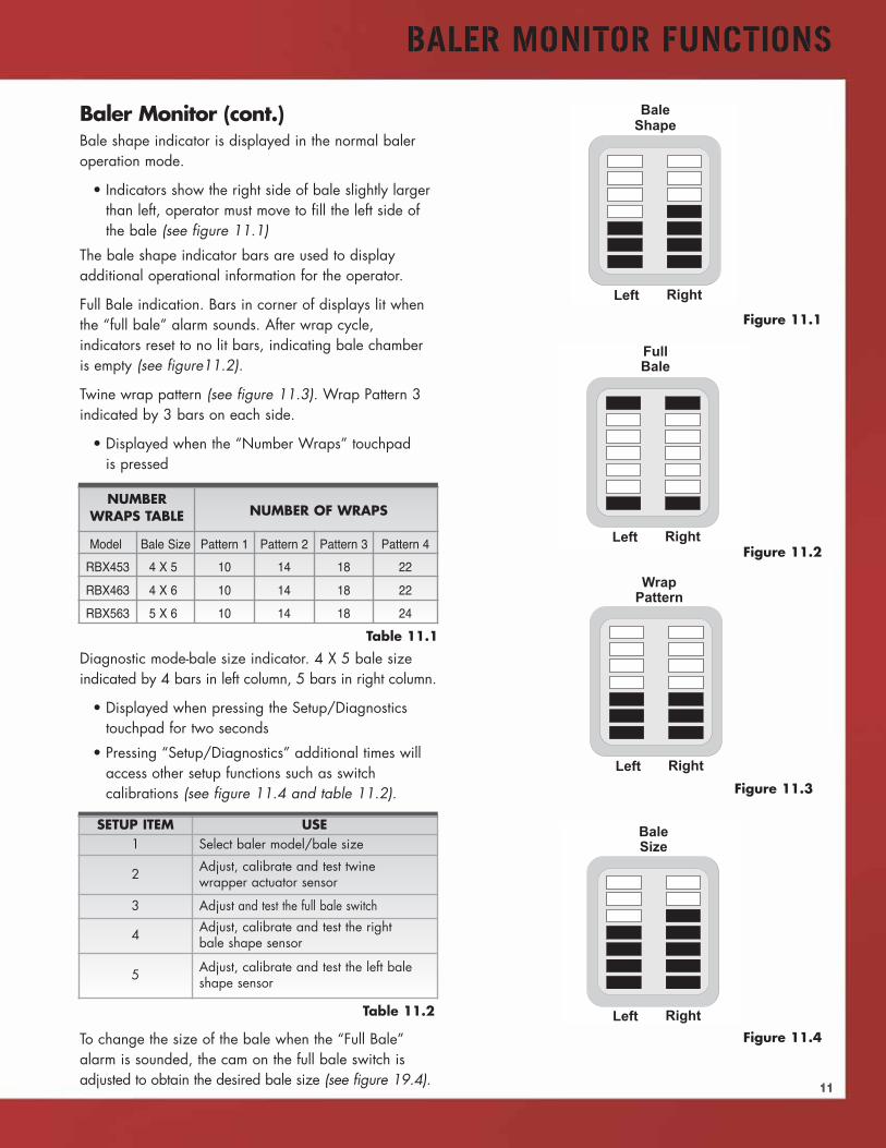
NUMBERWRAPS TABLE NUMBER OF WRAPS
Model Bale Size Pattern 1 Pattern 2 Pattern 3 Pattern 4
RBX453 4 X 5 10 14 18 22
RBX463 4 X 6 10 14 18 22
RBX563 5 X 6 10 14 18 24
WrapPattern
BaleSize
Figure 11.3
Figure 11.4
Table 11.1
Table 11.2
Baler Monitor (cont.)Bale shape indicator is displayed in the normal baleroperation mode.
• Indicators show the right side of bale slightly largerthan left, operator must move to fill the left side ofthe bale (see figure 11.1)
The bale shape indicator bars are used to displayadditional operational information for the operator.
Full Bale indication. Bars in corner of displays lit whenthe “full bale” alarm sounds. After wrap cycle,indicators reset to no lit bars, indicating bale chamberis empty (see figure11.2).
Twine wrap pattern (see figure 11.3). Wrap Pattern 3indicated by 3 bars on each side.
• Displayed when the “Number Wraps” touchpadis pressed
Diagnostic mode-bale size indicator. 4 X 5 bale sizeindicated by 4 bars in left column, 5 bars in right column.
• Displayed when pressing the Setup/Diagnosticstouchpad for two seconds
• Pressing “Setup/Diagnostics” additional times willaccess other setup functions such as switchcalibrations (see figure 11.4 and table 11.2).
To change the size of the bale when the “Full Bale”alarm is sounded, the cam on the full bale switch isadjusted to obtain the desired bale size (see figure 19.4).
SETUP ITEM USE1 Select baler model/bale size
2 Adjust, calibrate and test twinewrapper actuator sensor
3 Adjust and test the full bale switch
4 Adjust, calibrate and test the rightbale shape sensor
5 Adjust, calibrate and test the left baleshape sensor
12
BALER OPERATION
Connecting the Baler to the TractorBaler performance can be directly affected by certaintractor adjustments. Prior to connecting the baler to thetractor, take some time to assure tractor conditions meetthe following standards. Specific details for each stepare in the Operator's Manual.
• Tractor meets minimum size requirements. Considerrotor-cutter power requirements, if equipped; andassure the size and weight of the tractor is sufficientto control the weight of the baler, especially ongrades and inclines (see table 12.1).
• Adjust the tractor tread width so the wheels do notrun over the windrow. Use a tractor with sufficientground clearance to prevent crop from snaggingand bunching on the underside of the tractor.
• Refer to figure 12.1 for measurements to assure thecorrect drawbar-to-PTO shaft dimensional relationshipposition prior to connecting the baler hitch andPTO shaft.
• Three-point hitch lower arms should be removed ifat all possible to avoid the possibility of drivelinedamage due to contact with the hitch arms.
• Install the hitch pin from the bottom up to reducecrop snagging. Use 1- or 1-1/4" diameter by6" long pin or bolt. Install the safety chain asspecified before road transport.
• Move the jack to the operation storage position
• Verify the correct PTO shaft length after the balerhitch is connected to the tractor drawbar. Seeinstructions in the Operator's Manual to assureadequate operating clearance.
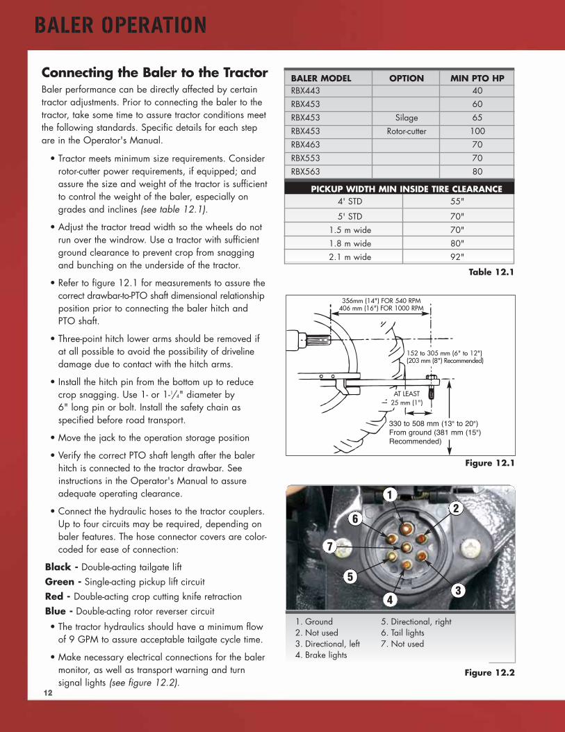
• Connect the hydraulic hoses to the tractor couplers.Up to four circuits may be required, depending onbaler features. The hose connector covers are color-coded for ease of connection:
Black - Double-acting tailgate liftGreen - Single-acting pickup lift circuitRed - Double-acting crop cutting knife retractionBlue - Double-acting rotor reverser circuit
• The tractor hydraulics should have a minimum flowof 9 GPM to assure acceptable tailgate cycle time.
• Make necessary electrical connections for the balermonitor, as well as transport warning and turnsignal lights (see figure 12.2).
BALER MODEL OPTION MIN PTO HPRBX443 40RBX453 60RBX453 Silage 65RBX453 Rotor-cutter 100RBX463 70RBX553 70RBX563 80
PICKUP WIDTH MIN INSIDE TIRE CLEARANCE4' STD 55"
5' STD 70"1.5 m wide 70"1.8 m wide 80"2.1 m wide 92"
Figure 12.1
Table 12.1
356mm (14") FOR 540 RPM406 mm (16") FOR 1000 RPM
152 to 305 mm (6" to 12")(203 mm (8") Recommended)
330 to 508 mm (13" to 20")From ground (381 mm (15")Recommended)
AT LEAST25 mm (1")
Figure 12.2
1. Ground2. Not used3. Directional, left4. Brake lights
5. Directional, right6. Tail lights7. Not used
3
12
4
5
6
7
13
BALER OPERATION
• Refer to the Operator's Manual for correct wiringconnections for the monitor, depending on the type oftractor electrical system.
• Newer tractors have a mating lighting connector,with wiring compatible with the baler circuits. Oldertractors may require addition of wiring connectionsfor proper lighting operation.
Loading TwineTwine used in a round baler application is lessdemanding than that for square balers, however, qualitytwine of consistent thickness and strength is important inmaintaining bale integrity, especially with repeatedhandling and long-term storage.
One twine box is mounted on each side of the baler.Twine loading is similar on twine-only and twine-net balers.
• Each box holds three balls of twine
• Thread inside loose end of front ball throughwireform or angle guide above the ball, thenthrough twine tension clamp
• Thread twine out of front of twine box.
• Twine tension adjusted to 8-12 lb. pull. Twine tootight may not start properly. Twine too loose maybe loose on bale and may not cut properly.
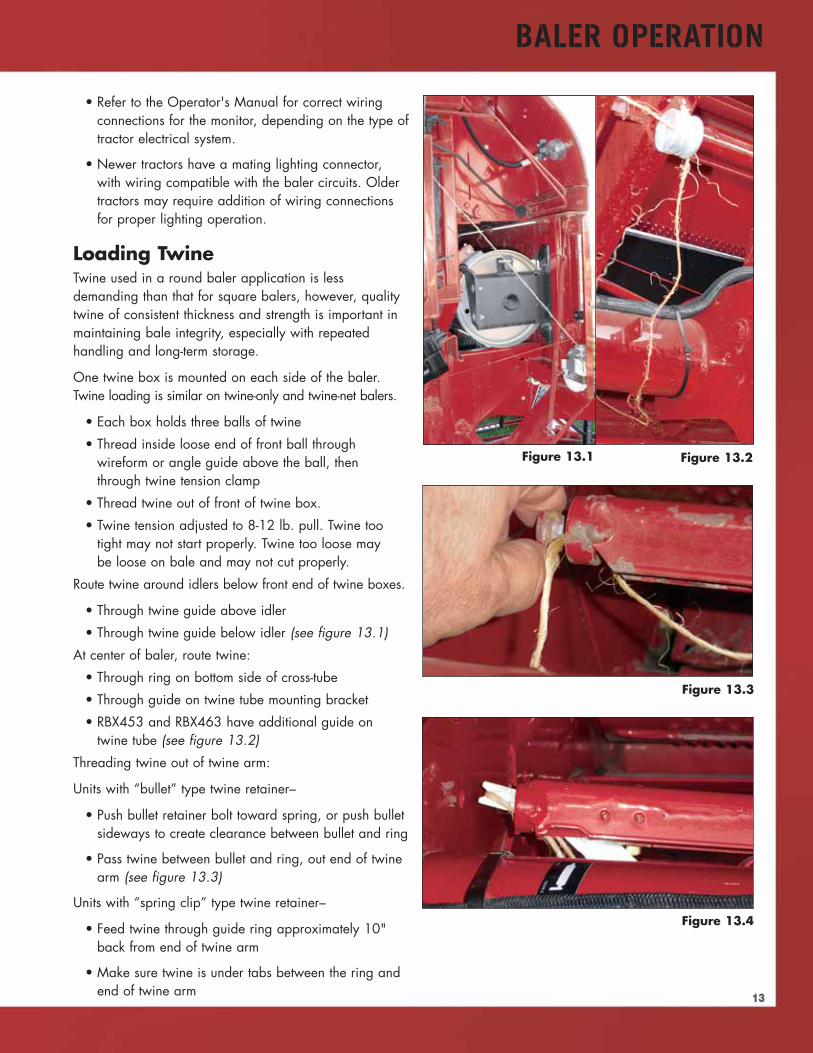
Route twine around idlers below front end of twine boxes.
• Through twine guide above idler
• Through twine guide below idler (see figure 13.1)
At center of baler, route twine:
• Through ring on bottom side of cross-tube
• Through guide on twine tube mounting bracket
• RBX453 and RBX463 have additional guide ontwine tube (see figure 13.2)
Threading twine out of twine arm:
Units with “bullet” type twine retainer–
• Push bullet retainer bolt toward spring, or push bulletsideways to create clearance between bullet and ring
• Pass twine between bullet and ring, out end of twinearm (see figure 13.3)
Units with “spring clip” type twine retainer–
• Feed twine through guide ring approximately 10"back from end of twine arm
• Make sure twine is under tabs between the ring andend of twine arm
Figure 13.1 Figure 13.2
Figure 13.3
Figure 13.4
14
BALER OPERATION
BALERMODEL
BALECHAMBER
WIDTH
MAX. WIDTHOF NET OR
TUBE
MIN WIDTHOF NET OR
TUBE
RBX453/463 46.5" 52" 44.5"
RBX553/563 61.5" 67" 59.5"
Table 14.1
Figure 14.2
Figure 14.3
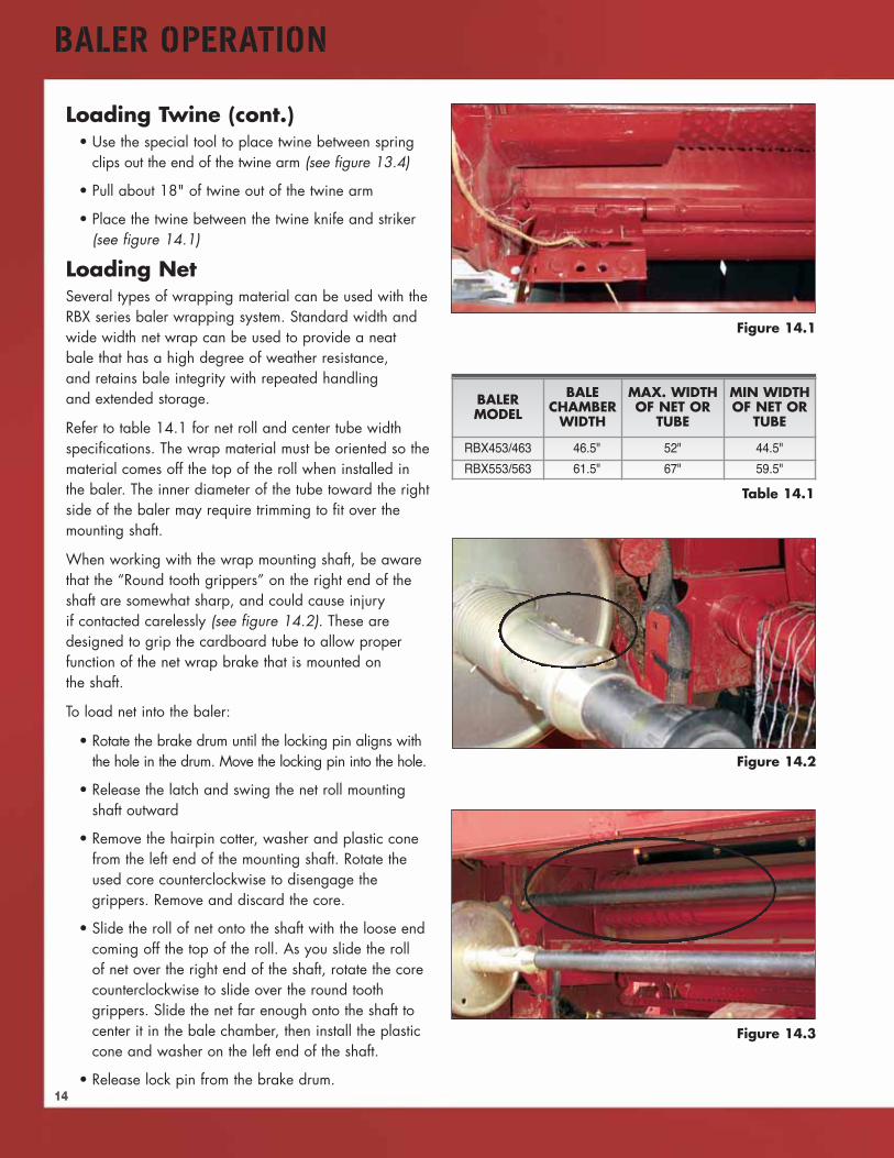
Loading Twine (cont.)• Use the special tool to place twine between spring
clips out the end of the twine arm (see figure 13.4)
• Pull about 18" of twine out of the twine arm
• Place the twine between the twine knife and striker(see figure 14.1)
Loading NetSeveral types of wrapping material can be used with theRBX series baler wrapping system. Standard width andwide width net wrap can be used to provide a neatbale that has a high degree of weather resistance,and retains bale integrity with repeated handlingand extended storage.
Refer to table 14.1 for net roll and center tube widthspecifications. The wrap material must be oriented so thematerial comes off the top of the roll when installed inthe baler. The inner diameter of the tube toward the rightside of the baler may require trimming to fit over themounting shaft.
When working with the wrap mounting shaft, be awarethat the “Round tooth grippers” on the right end of theshaft are somewhat sharp, and could cause injuryif contacted carelessly (see figure 14.2). These aredesigned to grip the cardboard tube to allow properfunction of the net wrap brake that is mounted onthe shaft.
To load net into the baler:
• Rotate the brake drum until the locking pin aligns withthe hole in the drum. Move the locking pin into the hole.
• Release the latch and swing the net roll mountingshaft outward
• Remove the hairpin cotter, washer and plastic conefrom the left end of the mounting shaft. Rotate theused core counterclockwise to disengage thegrippers. Remove and discard the core.
• Slide the roll of net onto the shaft with the loose endcoming off the top of the roll. As you slide the rollof net over the right end of the shaft, rotate the corecounterclockwise to slide over the round toothgrippers. Slide the net far enough onto the shaft tocenter it in the bale chamber, then install the plasticcone and washer on the left end of the shaft.
• Release lock pin from the brake drum.
Figure 14.1
15
BALER OPERATION
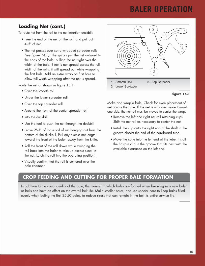
Loading Net (cont.)To route net from the roll to the net insertion duckbill:
• Free the end of the net on the roll, and pull out4'-5' of net.
• The net passes over spiral-wrapped spreader rolls(see figure 14.3). The spirals pull the net outward tothe ends of the bale, pulling the net tight over thewidth of the bale. If net is not spread across the fullwidth of the rolls, it will spread out while wrappingthe first bale. Add an extra wrap on first bale toallow full width wrapping after the net is spread.
Route the net as shown in figure 15.1:
• Over the smooth roll
• Under the lower spreader roll
• Over the top spreader roll
• Around the front of the center spreader roll
• Into the duckbill
• Use the tool to push the net through the duckbill
• Leave 2"-3" of loose tail of net hanging out from thebottom of the duckbill. Pull any excess net lengthtoward the front of the baler, away from the knife.
• Roll the front of the roll down while swinging theroll back into the baler to take up excess slack inthe net. Latch the roll into the operating position.
• Visually confirm that the roll is centered over thebale chamber
Make and wrap a bale. Check for even placement ofnet across the bale. If the net is wrapped more towardone side, the net roll must be moved to center the wrap.
• Remove the left and right net roll retaining clips.Shift the net roll as necessary to center the net.
• Install the clip onto the right end of the shaft in thegroove closest the end of the cardboard tube.
• Move the cone into the left end of the tube. Installthe hairpin clip in the groove that fits best with theavailable clearance on the left end.
Figure 15.1
1. Smooth Roll 3. Top Spreader
2. Lower Spreader
1
2
3
CROP FEEDING AND CUTTING FOR PROPER BALE FORMATION
In addition to the visual quality of the bale, the manner in which bales are formed when breaking in a new baleror belts can have an effect on the overall belt life. Make smaller bales, and use special care to keep bales filledevenly when baling the first 25-50 bales, to reduce stress that can remain in the belt its entire service life.
16
BALER OPERATION
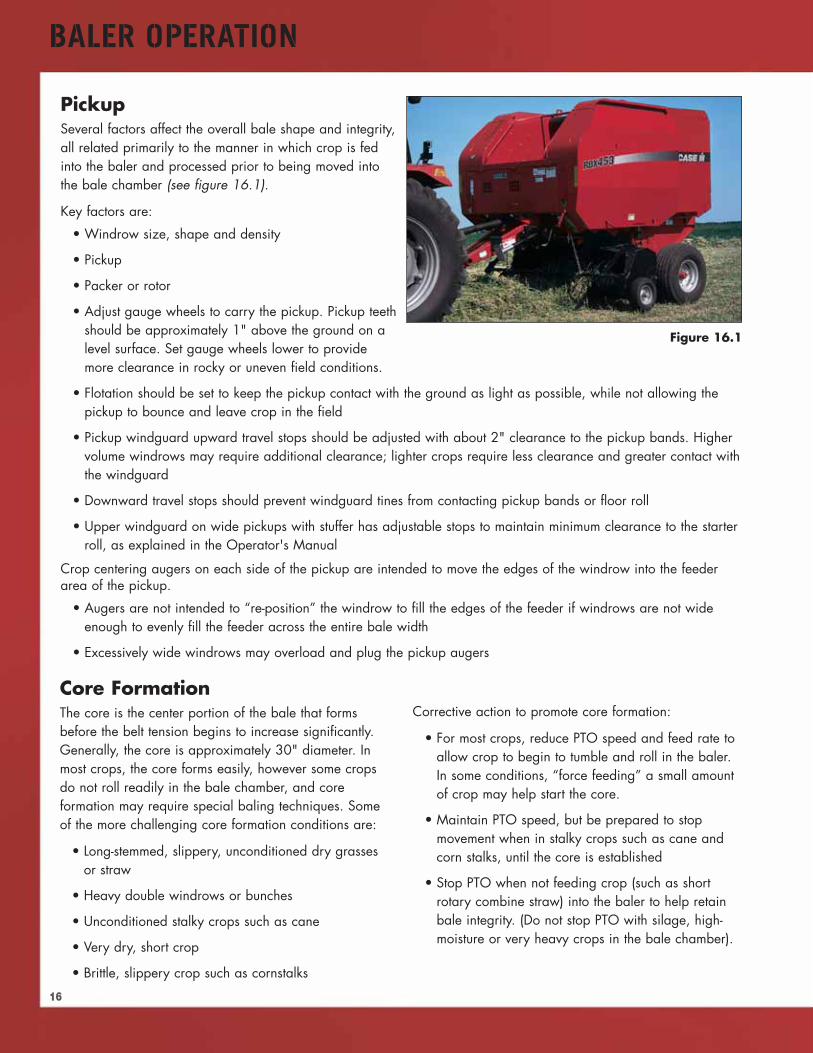
PickupSeveral factors affect the overall bale shape and integrity,all related primarily to the manner in which crop is fedinto the baler and processed prior to being moved intothe bale chamber (see figure 16.1).
Key factors are:
• Windrow size, shape and density
• Pickup
• Packer or rotor
• Adjust gauge wheels to carry the pickup. Pickup teethshould be approximately 1" above the ground on alevel surface. Set gauge wheels lower to providemore clearance in rocky or uneven field conditions.
• Flotation should be set to keep the pickup contact with the ground as light as possible, while not allowing thepickup to bounce and leave crop in the field
• Pickup windguard upward travel stops should be adjusted with about 2" clearance to the pickup bands. Highervolume windrows may require additional clearance; lighter crops require less clearance and greater contact withthe windguard
• Downward travel stops should prevent windguard tines from contacting pickup bands or floor roll
• Upper windguard on wide pickups with stuffer has adjustable stops to maintain minimum clearance to the starterroll, as explained in the Operator's Manual
Crop centering augers on each side of the pickup are intended to move the edges of the windrow into the feederarea of the pickup.
• Augers are not intended to “re-position” the windrow to fill the edges of the feeder if windrows are not wideenough to evenly fill the feeder across the entire bale width
• Excessively wide windrows may overload and plug the pickup augers
Figure 16.1
Core FormationThe core is the center portion of the bale that formsbefore the belt tension begins to increase significantly.Generally, the core is approximately 30" diameter. Inmost crops, the core forms easily, however some cropsdo not roll readily in the bale chamber, and coreformation may require special baling techniques. Someof the more challenging core formation conditions are:
• Long-stemmed, slippery, unconditioned dry grassesor straw
• Heavy double windrows or bunches
• Unconditioned stalky crops such as cane
• Very dry, short crop
• Brittle, slippery crop such as cornstalks
Corrective action to promote core formation:
• For most crops, reduce PTO speed and feed rate toallow crop to begin to tumble and roll in the baler.In some conditions, “force feeding” a small amountof crop may help start the core.
• Maintain PTO speed, but be prepared to stopmovement when in stalky crops such as cane andcorn stalks, until the core is established
• Stop PTO when not feeding crop (such as shortrotary combine straw) into the baler to help retainbale integrity. (Do not stop PTO with silage, high-moisture or very heavy crops in the bale chamber).
17
BALER OPERATION
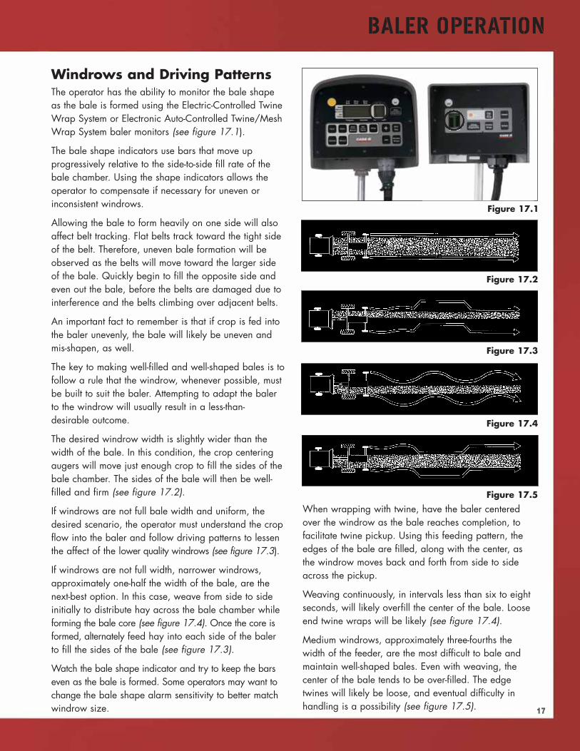
Windrows and Driving PatternsThe operator has the ability to monitor the bale shapeas the bale is formed using the Electric-Controlled TwineWrap System or Electronic Auto-Controlled Twine/MeshWrap System baler monitors (see figure 17.1).
The bale shape indicators use bars that move upprogressively relative to the side-to-side fill rate of thebale chamber. Using the shape indicators allows theoperator to compensate if necessary for uneven orinconsistent windrows.
Allowing the bale to form heavily on one side will alsoaffect belt tracking. Flat belts track toward the tight sideof the belt. Therefore, uneven bale formation will beobserved as the belts will move toward the larger sideof the bale. Quickly begin to fill the opposite side andeven out the bale, before the belts are damaged due tointerference and the belts climbing over adjacent belts.
An important fact to remember is that if crop is fed intothe baler unevenly, the bale will likely be uneven andmis-shapen, as well.
The key to making well-filled and well-shaped bales is tofollow a rule that the windrow, whenever possible, mustbe built to suit the baler. Attempting to adapt the balerto the windrow will usually result in a less-than-desirable outcome.
The desired windrow width is slightly wider than thewidth of the bale. In this condition, the crop centeringaugers will move just enough crop to fill the sides of thebale chamber. The sides of the bale will then be well-filled and firm (see figure 17.2).
If windrows are not full bale width and uniform, thedesired scenario, the operator must understand the cropflow into the baler and follow driving patterns to lessenthe affect of the lower quality windrows (see figure 17.3).
If windrows are not full width, narrower windrows,approximately one-half the width of the bale, are thenext-best option. In this case, weave from side to sideinitially to distribute hay across the bale chamber whileforming the bale core (see figure 17.4). Once the core isformed, alternately feed hay into each side of the balerto fill the sides of the bale (see figure 17.3).
Watch the bale shape indicator and try to keep the barseven as the bale is formed. Some operators may want tochange the bale shape alarm sensitivity to better matchwindrow size.
Figure 17.1
Figure 17.2
Figure 17.3
Figure 17.4
Figure 17.5
When wrapping with twine, have the baler centeredover the windrow as the bale reaches completion, tofacilitate twine pickup. Using this feeding pattern, theedges of the bale are filled, along with the center, asthe windrow moves back and forth from side to sideacross the pickup.
Weaving continuously, in intervals less than six to eightseconds, will likely overfill the center of the bale. Looseend twine wraps will be likely (see figure 17.4).
Medium windrows, approximately three-fourths thewidth of the feeder, are the most difficult to bale andmaintain well-shaped bales. Even with weaving, thecenter of the bale tends to be over-filled. The edgetwines will likely be loose, and eventual difficulty inhandling is a possibility (see figure 17.5).
BALER OPERATION
18
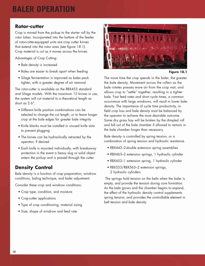
Rotor-cutterCrop is moved from the pickup to the starter roll by therotor lobes. Incorporated into the bottom of the feederof rotor-cutter-equipped units are crop cutter knivesthat extend into the rotor area (see figure 18.1).Crop material is cut as it moves across the knives.
Advantages of Crop Cutting:
• Bale density is increased
• Bales are easier to break apart when feeding
• Silage fermentation is improved as bales packtighter, with a greater degree of air removal
The rotor-cutter is available on the RBX453 standardand Silage models. With the maximum 15 knives in use,the system will cut material to a theoretical length asshort as 2.6".
• Different knife position combinations can beselected to change the cut length, or to leave longercrop at the bale edges for greater bale integrity
• Knife blanks must be installed in unused knife slotsto prevent plugging
• The knives can be hydraulically retracted by theoperator, if desired
• Each knife is mounted individually, with breakawayprotection in the event a heavy slug or solid objectenters the pickup and is passed through the cutter
Density ControlBale density is a function of crop preparation, windrowconditions, baling technique, and baler adjustment.
Consider these crop and windrow conditions:
• Crop type, condition, and moisture
• Crop-cutter applications
• Type of crop conditioning, material sizing
• Size, shape of windrow and feed rate
The more time the crop spends in the baler, the greaterthe bale density. Movement across the rollers as thebale rotates presses more air from the crop mat, andallows crop to “settle” together, resulting in a tighterbale. Fast feed rates and short cycle times, a commonoccurrence with large windrows, will result in lower baledensity. The importance of cycle time productivity, in-field crop loss and bale density must be balanced bythe operator to achieve the most desirable outcome.Some dry grass hay will be broken by the dimpled rolland fall out of the bale chamber if allowed to remain inthe bale chamber longer than necessary.
Bale density is controlled by spring tension, or acombination of spring tension and hydraulic resistance.
• RBX443–2-double extension spring assemblies
• RBX463–2 extension springs, 1 hydraulic cylinder
• RBX453–1 extension spring, 1 hydraulic cylinder
• RBX553/RBX563–2 extension springs,2 hydraulic cylinders
The springs hold tension on the belts when the baler isempty, and provide the tension during core formation.As the bale grows and the chamber begins to expand,the effect of the hydraulic density control supplementsspring tension, and provides the controllable element inbelt tension and bale density.
Figure 18.1
19
BALER OPERATION
Figure 19.1
Figure 19.3
Figure 19.2
Bale SizeBale size is adjusted in either of two ways:
• Balers with Electric-Controlled Twine Wrap System–to change the size of the bale when the “Full Bale”alarm is sounded, the cam on the full bale switch isadjusted to obtain the desired bale size (see figure19.4).
• Balers equipped with Electronic Auto-ControlledTwine/Mesh Wrap System–set bale sizeelectronically using the baler monitor
ALFALFA GRASS HAY STRAW SILAGERBX453 110 - 152 Bar 110 - 172 Bar 83 - 138 Bar 103 - 158 Bar
1600 - 2200 PSI 1600 - 2500 PSI 1200 - 2000 PSI 1500 - 2300 PSI
RBX463 110 -152 Bar 110 - 172 Bar 83 - 138 Bar 103 - 158 Bar
1600 - 2200 PSI 1600 - 2500 PSI 1200 - 2000 PSI 1500 - 2300 PSI
RBX553 90 - 138 Bar 90 - 138 Bar 69 - 110 Bar
1300 - 2000 PSI 1300 - 2000 PSI 1000 - 1600 PSI
RBX563 90 - 138 Bar 90 - 138 Bar 69 - 110 Bar1300 - 2000 PSI 1300 - 2000 PSI 1000 - 1600 PSI
Table 19.1
Figure 19.4
Density Setting Recommendations
1. Bale Size Adjustment
1
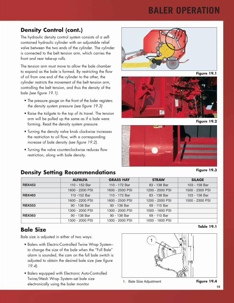
Density Control (cont.)The hydraulic density control system consists of a self-contained hydraulic cylinder with an adjustable reliefvalve between the two ends of the cylinder. The cylinderis connected to the belt tension arm, which carries thefront and rear take-up rolls.
The tension arm must move to allow the bale chamberto expand as the bale is formed. By restricting the flowof oil from one end of the cylinder to the other, thecylinder restricts the movement of the belt tension arm,controlling the belt tension, and thus the density of thebale (see figure 19.1).
• The pressure gauge on the front of the baler registersthe density system pressure (see figure 19.3)
• Raise the tailgate to the top of its travel. The tensionarm will be pulled up the same as if a bale wereforming. Read the density system pressure.
• Turning the density valve knob clockwise increasesthe restriction to oil flow, with a correspondingincrease of bale density (see figure 19.2).
• Turning the valve counterclockwise reduces flowrestriction, along with bale density.
20
MAINTENANCE
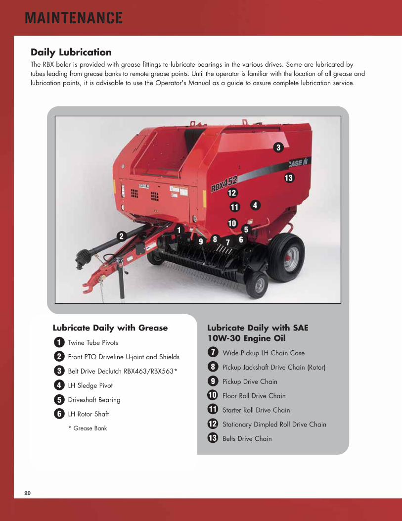
Lubricate Daily with Grease
Twine Tube Pivots
Front PTO Driveline U-joint and Shields
Belt Drive Declutch RBX463/RBX563*
LH Sledge Pivot
Driveshaft Bearing
LH Rotor Shaft
* Grease Bank
Lubricate Daily with SAE10W-30 Engine Oil
Wide Pickup LH Chain Case
Pickup Jackshaft Drive Chain (Rotor)
Pickup Drive Chain
Floor Roll Drive Chain
Starter Roll Drive Chain
Stationary Dimpled Roll Drive Chain
Belts Drive Chain
12
3
4
56789
10
11
12
13
1
2
4
5
6
7
8
9
10
12
13
11
Daily LubricationThe RBX baler is provided with grease fittings to lubricate bearings in the various drives. Some are lubricated bytubes leading from grease banks to remote grease points. Until the operator is familiar with the location of all grease andlubrication points, it is advisable to use the Operator's Manual as a guide to assure complete lubrication service.
3
MAINTENANCE
21
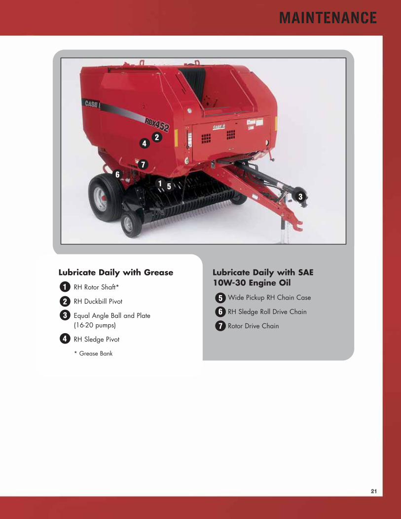
Lubricate Daily with Grease
RH Rotor Shaft*
RH Duckbill Pivot
Equal Angle Ball and Plate(16-20 pumps)
RH Sledge Pivot
* Grease Bank
Lubricate Daily with SAE10W-30 Engine Oil
Wide Pickup RH Chain Case
RH Sledge Roll Drive Chain
Rotor Drive Chain
1
2
3
4
56
7
1
2
4
5
6
7
3
MAINTENANCE
22
MaintenanceScheduled maintenance is an essential part of keeping your RBX Baler working at top performance, with the highestlevel of reliability and minimal downtime.
We know it can be very easy to sidestep the time necessary for some routine maintenance. The people whodesigned your baler have taken your hectic schedule into consideration and have included convenient features tosave time. Operators must still make some time to assure all necessary maintenance is performed in a timely andconscientious manner.
In addition to prioritizing the time necessary to perform normal maintenance operations, using top quality Case IHreplacement parts and lubricants will go far in assuring your efforts to will be rewarded with trouble-free andproductive baling.
Cleaning the BalerPrior to performing regular inspections, adjustments and lubrication, the baler should be cleaned following use.This is especially critical if the baler is stored outdoors where it is exposed to rain and high moisture. Using thetime while cleaning to visually check the unit is a good way to perform a basic baler inspection.
Compressed air is most effective for removing chaff anddebris from the many cracks, crevices and corners on thebaler. Another highly effective, and very portable option,is the high velocity, high volume air blast from a gas- orelectric-powered leaf blower. Remember to wear eyeprotection any time air is used to clean the baler.
Do not use water to clean the baler. Any debris thatinadvertently remains after cleaning, but is soaked withwater, may become the source of accelerated rust andcorrosion damage.
Use the following maintenance guide (see table 23.1)as a reference of prescribed service points and intervals.This guide is part of the baler Operator's Manual.
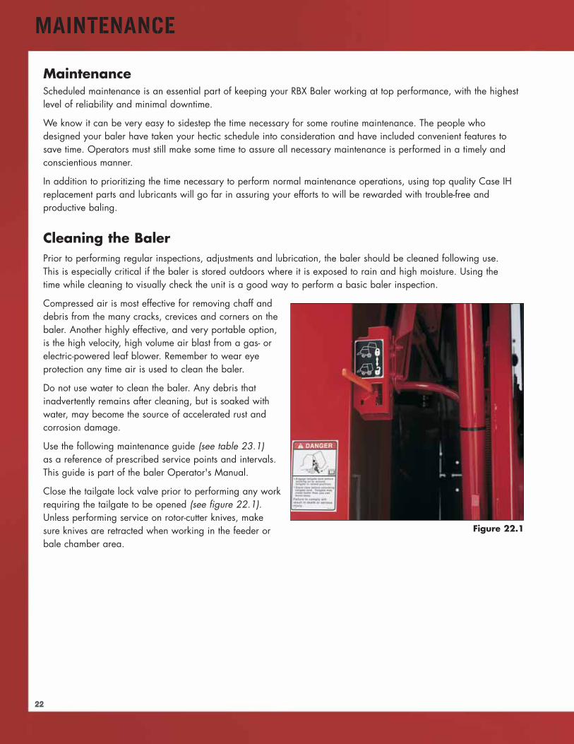
Close the tailgate lock valve prior to performing any workrequiring the tailgate to be opened (see figure 22.1).Unless performing service on rotor-cutter knives, makesure knives are retracted when working in the feeder orbale chamber area.
Figure 22.1
23
MAINTENANCE
SERVICE ITEM MAXIMUM HOURLY INTERVAL
8/DAY 50/WEEK 1000/YEAR8 Hour lubrication XInspect and tighten hardware XCheck drive chains for proper adjustment X50 hour lubrication XCheck for failing bearings (heat) XInspect pickup tines XInspect the belts and lacing XCheck roll scraper adjustment XTorque tailgate belt adjusting roll bolts(Middle tailgate idler roll)Inspect pickup cam bearings XCheck tire pressure X1000 hour lubrication XChange gearbox oil XCheck hydraulic belt tension fluid level X
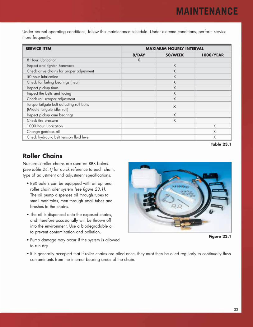
Roller ChainsNumerous roller chains are used on RBX balers.(See table 24.1) for quick reference to each chain,type of adjustment and adjustment specifications.
• RBX balers can be equipped with an optionalroller chain oiler system (see figure 23.1).The oil pump dispenses oil through tubes tosmall manifolds, then through small tubes andbrushes to the chains.
• The oil is dispensed onto the exposed chains,and therefore occasionally will be thrown offinto the environment. Use a biodegradable oilto prevent contamination and pollution.
• Pump damage may occur if the system is allowedto run dry
• It is generally accepted that if roller chains are oiled once, they must then be oiled regularly to continually flushcontaminants from the internal bearing areas of the chain.
Figure 23.1
Table 23.1
Under normal operating conditions, follow this maintenance schedule. Under extreme conditions, perform servicemore frequently.
X
24
MAINTENANCE
CHAIN LOCATION TYPE OF SPEC. SPEC. SPRINGADJUSTMENT DEFLECTION ADJUSTMENT
Starter Roll Drive Chain Spring-loaded idler 7-3/8"
Stationary dimpled roll drive chain Spring-loaded idler 7-3/8"
Floor roll drive chain Spring-loaded idler 7-3/8"
Sledge roll drive chain Spring-loaded idler 2-1/2"
Belt drive roll drive chain Spring-loaded idler 14-3/4"
Wide pickup drive chain Spring-loaded idler 5-1/8"
Wide pickup left drive chain Solid idler 3/16"-3/4"
Wide pickup right drive chain Solid idler 3/16"-3/4"
Standard pickup drive chain Solid tightener 3/16"-3/4"
CROP CUTTER BALERS
LH Jackshaft drive idler Spring-loaded idler 0-5/8"
RH Jackshaft drive idler Spring-loaded idler 0-5/8"
Pickup drive idler Spring-loaded idler 0-5/8"
Rotor pickup drive chain Spring-loaded idler 4-3/4"
Gearbox• The main gearbox has a level check dipstick. SAE 80W90 lubricant is used for replenishment. Check weekly,
or every 50 hours of operation.
Bale Density and Belt TensionThe bale density system is a sealed and self-contained hydraulic system. A hose connected to a tractor remotehydraulic circuit is used to charge the density control cylinder. The complete procedure is explained in theOperator's Manual.
The tension must be removed from the baler belts before performing service on the belts and rollers.
• Tailgate is opened until the lock pin is below the tension arm
• Pull down and rotate the handle, moving the pin into position under the tension arm
• Lower the tailgate until the pin is holding the tension. The belts will continue to loosen as the tailgate is lowered
• Close the tailgate lock valve before working under or near the tailgate
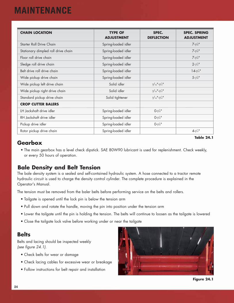
BeltsBelts and lacing should be inspected weekly(see figure 24.1).
• Check belts for wear or damage
• Check lacing cables for excessive wear or breakage
• Follow instructions for belt repair and installation
Table 24.1
Figure 24.1
25
MAINTENANCE
Belt Operation• Observe belt tracking during operation. Belts will normally shift as the bale is formed
• Contact with belt guides is normal, but belts should not curl against guides or flip over
• Rollers can be shifted to change belt tension across the baler, altering tracking characteristics of the belts
• Belt slippage at core start can be corrected by increasing density spring tension. Additional tension can beadded by re-positioning upper rear tailgate roller.
• Belt slippage at full bale can be reduced with infeed disc kit to reduce friction between bale and baler sides
• Inspect rollers for material debris that can affect belt tracking and tension
Rotor-cutterRotor-cutter knives must be kept sharp to maintain optimal crop cutting performance.
• Dull knives adversely affect the quality of cutting, and baler capacity
• Cutting with dull knives increases horsepower requirements and fuel consumption
• Spare knife set allows the baler cutter to be serviced quickly with minimal downtime
• Standard and hard-surfaced knives can be sharpened with a powered grinder
• Clamp knives with the serrated front edge of the knife down. Grind on the flat, back side of the knife.Hard-surfaced knives can be sharpened only on the back side.
Driveline ProtectionShear bolts are the most simple form of driveline protection. When a shear bolt is overloaded and fails,all or a portion of the baler stops functioning.
• The pickup on RBX453 rotor-cutter equipped balers is protected by a shear bolt
• Stop the tractor, and inspect the baler to determine the reason for the shear bolt failure
• If sufficient free movement is not available in the tractor PTO or baler driveline to align the shear bolt holes,it may be necessary to remove the PTO shaft to gain sufficient rotation
Slip clutches offer protection to components that may be momentarily overloaded. Often, a clutch may slip withoutthe operator being aware of the condition, as the overload passes and the machine continues to function normally.Slip clutches are friction disc type clutches.
• Slip clutches are used on the PTO driveline on all models, except the RBX453 Standard or Silage Models withrotor-cutter. Torque specifications vary between models
Other slip clutch applications on RBX balers:
• Sledge drive
• Standard (non-rotor-cutter) pickup
• Specifications vary for the different clutches on the baler. The Operator's Manual should be consulted if clutchesdo not function correctly, and require service or adjustment.
Jaw-type slip clutch
• Used on wide pickup, stuffer equipped balers
26
MAINTENANCE
Clutch Burnishing• Slip clutch discs may stick when the baler has been in storage. The clutch may not slip as designed, hindering
the protective effect of the clutch.
• Burnishing is a way of polishing the clutch components to relieve sticking, assuring proper clutch function
• Basic procedure is to reduce the clutch spring pressure, and block the output from turning. Slowly engagingthe PTO allows the clutch to slip momentarily, relieving any seizure and wearing away contamination that mayprevent the clutch from performing as designed.
• Reset the clutch pressure springs as specified in the Operator's Manual, in reference to the specific slip clutch
• It is highly recommended that this procedure be included in your dealer’s pre-season maintenance inspection
The rotor-cutter drive is protected by a cut-out type torque-limiting clutch. The cut-out clutch is designed to disengageat a pre-set torque limit.
• The cut-out clutch interrupts power, but does not re-set until the PTO is turned off, and the machine coasts toa stop. The clutch automatically re-sets.
• Clear the obstruction or crop accumulation that caused the torque overload before attempting to re-start the PTO
• No service, maintenance or adjustment is required for the cut-out clutch. Refer clutch repairs to yourauthorized dealer.
An apron belt drive clutch is also used on RBX463 and RBX563 balers. The clutch stops the belts when the tailgate isopened. See the Operator's Manual if adjustment is required to stop the belts at approximately 36" of tailgate opening.
Twine and Net KnivesTwine and net cutting knives must be sharpened periodically to maintain clean material cutoff.
• Twine knives can be removed and file sharpened. Be sure to keep the cutting surface straight and retain theoriginal bevel.
• Net knives can be removed and file sharpened. Be sure to keep the cutting surface straight and retain theoriginal bevel. Be sure to install the knife and comb properly. Install the comb first, followed by the knife withthe sharp knife edge installed against the comb.
27
TROUBLESHOOTING
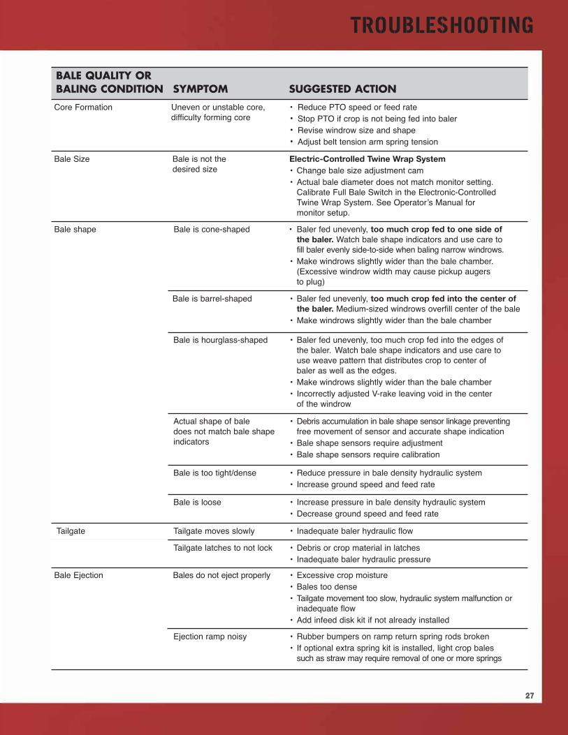
BALE QUALITY ORBALING CONDITION SYMPTOM SUGGESTED ACTION
Core Formation Uneven or unstable core,difficulty forming core
• Reduce PTO speed or feed rate• Stop PTO if crop is not being fed into baler• Revise windrow size and shape• Adjust belt tension arm spring tension
Bale Size Bale is not thedesired size
Electric-Controlled Twine Wrap System• Change bale size adjustment cam• Actual bale diameter does not match monitor setting.Calibrate Full Bale Switch in the Electronic-ControlledTwine Wrap System. See Operator’s Manual formonitor setup.
Bale shape Bale is cone-shaped • Baler fed unevenly, too much crop fed to one side ofthe baler. Watch bale shape indicators and use care tofill baler evenly side-to-side when baling narrow windrows.
• Make windrows slightly wider than the bale chamber.(Excessive windrow width may cause pickup augersto plug)
Bale is barrel-shaped • Baler fed unevenly, too much crop fed into the center ofthe baler. Medium-sized windrows overfill center of the bale
• Make windrows slightly wider than the bale chamber
Bale is hourglass-shaped • Baler fed unevenly, too much crop fed into the edges ofthe baler. Watch bale shape indicators and use care touse weave pattern that distributes crop to center ofbaler as well as the edges.
• Make windrows slightly wider than the bale chamber• Incorrectly adjusted V-rake leaving void in the centerof the windrow
Actual shape of baledoes not match bale shapeindicators
• Debris accumulation in bale shape sensor linkage preventingfree movement of sensor and accurate shape indication
• Bale shape sensors require adjustment• Bale shape sensors require calibration
Bale density Bale is too tight/dense • Reduce pressure in bale density hydraulic system• Increase ground speed and feed rate
Bale is loose • Increase pressure in bale density hydraulic system• Decrease ground speed and feed rate
Tailgate Tailgate moves slowly • Inadequate baler hydraulic flow
Tailgate latches to not lock • Debris or crop material in latches• Inadequate baler hydraulic pressure
Bale Ejection Bales do not eject properly • Excessive crop moisture• Bales too dense• Tailgate movement too slow, hydraulic system malfunction orinadequate flow
• Add infeed disk kit if not already installed
Ejection ramp noisy • Rubber bumpers on ramp return spring rods broken• If optional extra spring kit is installed, light crop balessuch as straw may require removal of one or more springs
TROUBLESHOOTING
28
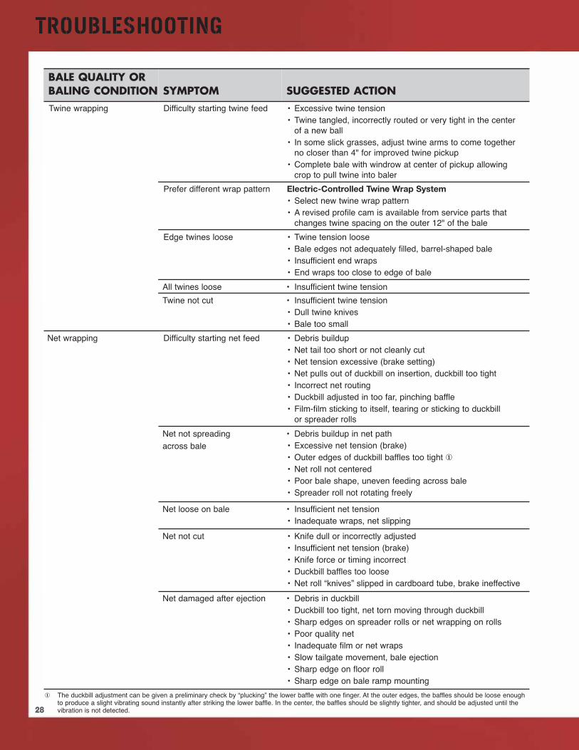
BALE QUALITY ORBALING CONDITION SYMPTOM SUGGESTED ACTIONTwine wrapping Difficulty starting twine feed • Excessive twine tension
• Twine tangled, incorrectly routed or very tight in the centerof a new ball
• In some slick grasses, adjust twine arms to come togetherno closer than 4" for improved twine pickup
• Complete bale with windrow at center of pickup allowingcrop to pull twine into baler
Prefer different wrap pattern Electric-Controlled Twine Wrap System• Select new twine wrap pattern• A revised profile cam is available from service parts thatchanges twine spacing on the outer 12" of the bale
Edge twines loose • Twine tension loose• Bale edges not adequately filled, barrel-shaped bale• Insufficient end wraps• End wraps too close to edge of bale
All twines loose • Insufficient twine tension
Twine not cut • Insufficient twine tension• Dull twine knives• Bale too small
Net wrapping Difficulty starting net feed • Debris buildup• Net tail too short or not cleanly cut• Net tension excessive (brake setting)• Net pulls out of duckbill on insertion, duckbill too tight• Incorrect net routing• Duckbill adjusted in too far, pinching baffle• Film-film sticking to itself, tearing or sticking to duckbillor spreader rolls
Net not spreadingacross bale
• Debris buildup in net path• Excessive net tension (brake)• Outer edges of duckbill baffles too tight ①
• Net roll not centered• Poor bale shape, uneven feeding across bale• Spreader roll not rotating freely
Net loose on bale • Insufficient net tension• Inadequate wraps, net slipping
Net not cut • Knife dull or incorrectly adjusted• Insufficient net tension (brake)• Knife force or timing incorrect• Duckbill baffles too loose• Net roll “knives” slipped in cardboard tube, brake ineffective
Net damaged after ejection • Debris in duckbill• Duckbill too tight, net torn moving through duckbill• Sharp edges on spreader rolls or net wrapping on rolls• Poor quality net• Inadequate film or net wraps• Slow tailgate movement, bale ejection• Sharp edge on floor roll• Sharp edge on bale ramp mounting
① The duckbill adjustment can be given a preliminary check by “plucking” the lower baffle with one finger. At the outer edges, the baffles should be loose enoughto produce a slight vibrating sound instantly after striking the lower baffle. In the center, the baffles should be slightly tighter, and should be adjusted until thevibration is not detected.

29
PARTS KITS/ACCESSORIES/ASSEMBLIES
Natural Sisal Twine• 100% biodegradable
• Consistent knot and tensile strength
• Mildew resistant
• Uniform thickness
• Only the best sisal fibers are used
• Every ball contains exact footage shown onthe label
Plastic Baling Twine• Provides maximum strength and ultimate
performance
• Will not rot
• Makes tight, uniform bales
• UV stabilized to withstand sunlight exposure
• Plastic twine-wrapped bales can be storedindoors/outdoors
• Diameter of twine is uniform throughout the ball
• Non-toxic to animals
110 Solar Degradable
100 Big Ball
110 Economy
110 High Visibility
125 High Visibility
140 High Visibility
110 High Visibility
All Round Bales
All Round Bales
All Round Bales
All Round Bales
All Round Bales
All Round Bales
All Round Bales
ROUND BALER TWINE (MONOFILAMENT)
16,000
20,000
20,000
20,000
20,000
20,000
28,000
Ft. Per Box TensileStrength (lbs.)
End UseApplication
110
125
140
90
110
All Round Bales
All Round Bales
All Round Bales
All Round Bales
All Round Bales
ROUND BALER TWINE (SLIT FILM)
20,000
20,000
20,000
25,000
28,000
Ft. Per Box TensileStrength (lbs.)
End UseApplication
180 Round Bales
ROUND BALER TWINE
16,000
Ft. perBale
KnotStrength (lbs.)
End UseApplication
GrossWt. (lbs.)
40 180 Round Silage Bales
RED WINDER UNTREATED TWINE
16,000
Ft. perBale
KnotStrength (lbs.)
End UseApplication
GrossWt. (lbs.)
40
30
PARTS KITS/ACCESSORIES/ASSEMBLIES
Width(Inches)
Length(Feet)
Length(Meters) End Use Application
5,000
6,200
9,840
9,840 MaxWrap
9,840
6,560
7,000
7,000 MaxWrap
6,560
1,524
1,890
3,000
3,000
3,000
2,000
2,134
2,134
2,000
48
48
48
51*
52
64
67*
67*
67
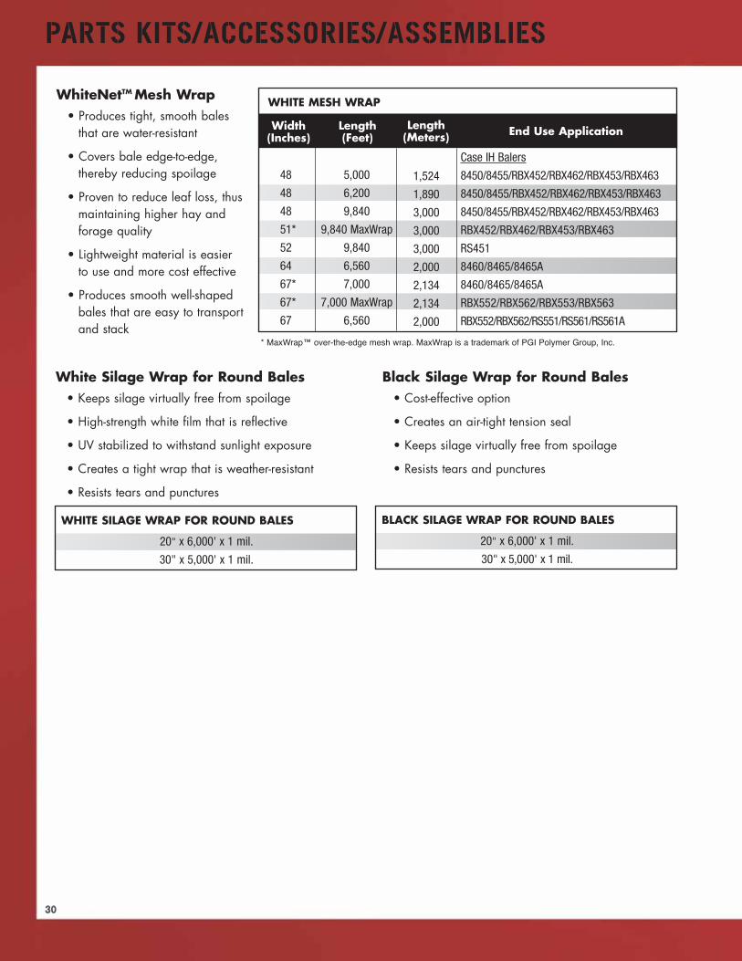
WhiteNetTM Mesh Wrap• Produces tight, smooth bales
that are water-resistant
• Covers bale edge-to-edge,thereby reducing spoilage
• Proven to reduce leaf loss, thusmaintaining higher hay andforage quality
• Lightweight material is easierto use and more cost effective
• Produces smooth well-shapedbales that are easy to transportand stack
Case IH Balers
8450/8455/RBX452/RBX462/RBX453/RBX463
8450/8455/RBX452/RBX462/RBX453/RBX463
8450/8455/RBX452/RBX462/RBX453/RBX463
RBX452/RBX462/RBX453/RBX463
RS451
8460/8465/8465A
8460/8465/8465A
RBX552/RBX562/RBX553/RBX563
RBX552/RBX562/RS551/RS561/RS561A
White Silage Wrap for Round Bales• Keeps silage virtually free from spoilage
• High-strength white film that is reflective
• UV stabilized to withstand sunlight exposure
• Creates a tight wrap that is weather-resistant
• Resists tears and punctures
Black Silage Wrap for Round Bales• Cost-effective option
• Creates an air-tight tension seal
• Keeps silage virtually free from spoilage
• Resists tears and punctures
BLACK SILAGE WRAP FOR ROUND BALES
20" x 6,000' x 1 mil.
30" x 5,000' x 1 mil.
WHITE SILAGE WRAP FOR ROUND BALES
20" x 6,000' x 1 mil.
30" x 5,000' x 1 mil.
WHITE MESH WRAP
* MaxWrap™ over-the-edge mesh wrap. MaxWrap is a trademark of PGI Polymer Group, Inc.
31
PARTS KITS/ACCESSORIES/ASSEMBLIES
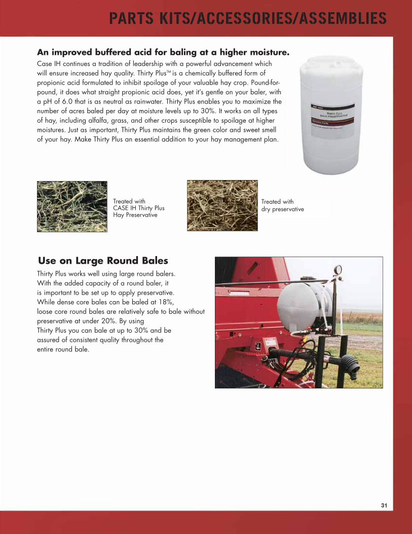
An improved buffered acid for baling at a higher moisture.Case IH continues a tradition of leadership with a powerful advancement whichwill ensure increased hay quality. Thirty PlusTM is a chemically buffered form ofpropionic acid formulated to inhibit spoilage of your valuable hay crop. Pound-for-pound, it does what straight propionic acid does, yet it’s gentle on your baler, witha pH of 6.0 that is as neutral as rainwater. Thirty Plus enables you to maximize thenumber of acres baled per day at moisture levels up to 30%. It works on all typesof hay, including alfalfa, grass, and other crops susceptible to spoilage at highermoistures. Just as important, Thirty Plus maintains the green color and sweet smellof your hay. Make Thirty Plus an essential addition to your hay management plan.
Treated withdry preservative
Treated withCASE IH Thirty PlusHay Preservative
Thirty Plus works well using large round balers.With the added capacity of a round baler, itis important to be set up to apply preservative.While dense core bales can be baled at 18%,loose core round bales are relatively safe to bale withoutpreservative at under 20%. By usingThirty Plus you can bale at up to 30% and beassured of consistent quality throughout theentire round bale.
Use on Large Round Bales

32
PARTS KITS/ACCESSORIES/ASSEMBLIES
Regular Profile 3-PlyContinuous Chevron Design
Case IH RBX Series Round BalersNew Lower 3-Ply Continuous Chevron Baler Belt Design
• Provides the perfect combination of positive yet gentle grip between crop and belts
• Exclusive lower profile Continuous Chevron design moves crop quickly to the baling chamberfor fast and efficient bale starts
• Low profile textured surface releases crop during bale formation for minimal leaf loss
• Features a self cleaning design for constant performance in the most difficult conditions
• High strength polyester/nylon construction provides the ideal combination of working tension,elongation (under load), and faster retention
• 3-Ply Low Profile Continuous Chevron Endless belts are also available for most RBX models.Case IH belts are truly endless with the highest tension rating in the industry.
Standards a Cut Above the Competition
New Lower Profile 3-PlyContinuous Chevron Design
33
PARTS KITS/ACCESSORIES/ASSEMBLIES
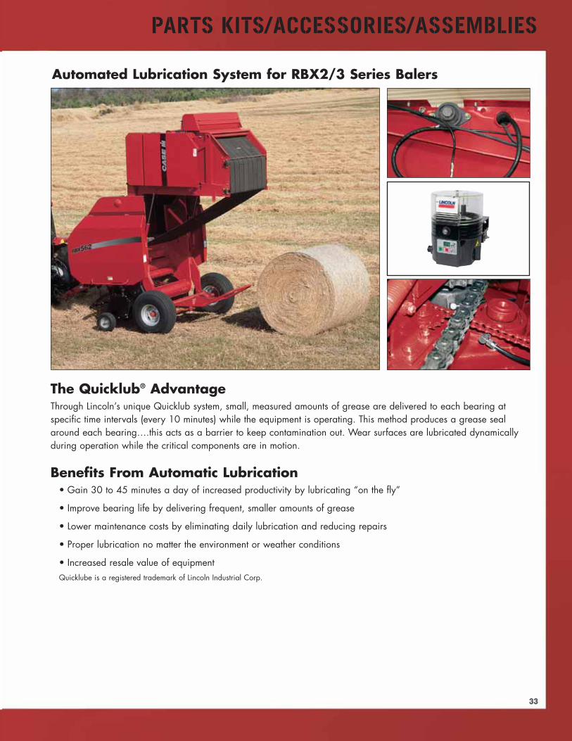
The Quicklub® AdvantageThrough Lincoln’s unique Quicklub system, small, measured amounts of grease are delivered to each bearing atspecific time intervals (every 10 minutes) while the equipment is operating. This method produces a grease sealaround each bearing….this acts as a barrier to keep contamination out. Wear surfaces are lubricated dynamicallyduring operation while the critical components are in motion.
Benefits From Automatic Lubrication• Gain 30 to 45 minutes a day of increased productivity by lubricating “on the fly”
• Improve bearing life by delivering frequent, smaller amounts of grease
• Lower maintenance costs by eliminating daily lubrication and reducing repairs
• Proper lubrication no matter the environment or weather conditions
• Increased resale value of equipmentQuicklube is a registered trademark of Lincoln Industrial Corp.
Automated Lubrication System for RBX2/3 Series Balers

34
PARTS KITS/ACCESSORIES/ASSEMBLIES
Keep all your baler chains running cooland lubricated automatically every timeyou activate the tailgate.
• Easy installation
• Fully adjustable flow
• Increases productivity
• Up to 300% increase in chain and sprocket life
Kit No. B96494 contains the LubeMinder® pump andenough brushes to lubricate all 7 chains found on theRBX 2/3 Series Balers. Installation is easy, taking onlya few hours when done by your dealer.
Lincoln's new, heavy-duty 14.4 voltPowerLuber gives you the powerto lubricate just about anything,anytime, anywhere.
• Two-speed switch for high-pressure orhigh-volume delivery
• Cycle indicator pin to monitor grease output
• “Smart” charging system delivers reliable power
All the features you need, including comfortable grip andbalanced design; hook for shoulder strap; built-in hose andcoupler holder; and a slim, compact carrying case.
Model 1442 - Part No. 87298560 - one battery
Model 1444 - Part No. 87298561 - two batteries
Case IH LubeMinder® Automatic Chain Lubrication System
Lincoln PowerLuber®
LubeMinder is a registered Trademark of Suburban MFG.
Powerluber is a registered trademark of Lincoln Industrial Corp.

PARTS KITS/ACCESSORIES/ASSEMBLIES
Features• Direct readout of
temperature in °F/°C• Multi-language• Adjustable for: Density of bale,
Hay cutting, Hay type• Displays running average• Backlit display for night use• Sturdy pistol grip handle• Extra-rugged 18" probe• Includes a 3" x 36 yd. roll of white baleage wrap
patch tape reorder - Part No. B94847
Specifications• Testing range: 35%–75% moisture• 1 year warranty
Moisture Testers – Hay
Features• Direct readout for % moisture
and temperature (°F std.–°C opt.)• Separate electronics module
from probe• Extra-rugged probe shaft made
from aircraft aluminum• Sturdy pistol-grip handle• 3 Models available: 18"(std.),
24" and 32" probe lengths• Padded carrying
case included
Specifications• Accurate throughout the normal range of stored,
baled Alfalfa, Timothy and Clover Hay• Testing range: 14.4%–44% moisture,
33°–250°F temperature• 1 year warranty
AccessoriesProbe Only: B500819 (18"), B505230 (24"),B500820 (32")
Features• Expanded low moisture
range down to 8%• Backlit display for night use• Built-in calibration button• Extra-rugged 20" probe for
testing square or round bales• Direct readout for % moisture
and temperature (°F/°C)• Above and below moisture
limit indication
Specifications• Accurate throughout the normal range of stored,
baled Alfalfa, Timothy and Clover Hay• Testing range: 8%–44% moisture, 32°–225°F (0°–
107°C) temperature• 1 year warranty
Part No. B505453
BHT-1 Baler Mounted Hay Tester
DHT-1 Portable Hay Tester
Part No. B500818 (18")B505229 (24")B505228 (32")
HMT-2 Portable Hay Tester
HMT-3 Portable Hay Tester
Part No. B94846
Features• Direct readout for % moisture –
while baling hay• Average of readings updated and
displayed every 3 to 5 seconds• Backlit display for night use• Built-in calibration button• Above and below moisture
limit indicator• Sturdy display module mounting
bracket with adjusting knobs• Includes sensor kit• Long-lasting sensor pad and
stainless steel hardware• Fits square or round balers
Specifications• Testing range: 8%–44% moisture• 1 year warranty
AccessoriesSensor Pad Kit (B505533)
• Sensor pad and boltsExtension Sensor Cable (B505459)
• 10' cable• Weather-proof connectors
Complete Sensor Kit (B505460)• Sensor pad and bolts• 25' sensor cable• Display module mounting bracket• 8' power cable
Part No. B505533
Part No. B50495
35
Part No. B505454
Case IH dealers are the standard for expert sales, service and support of the most technologically
advanced equipment in the world. They’re committed to understanding your business and providing
unique solutions to maximize your productivity.
From tractors to implements that meet the specific needs of your operation, Case IH dealers
offer a complete agricultural system aimed at increasing your productivity and profitability.
Coupled with timely parts and service, and flexible financial solutions through
CNH Capital, Case IH dealers provide a total package to ensure you’re always
performing at your best.
But most importantly, Case IH dealers offer planning for the long-term growth of
your business. By staying at the forefront of agronomic issues and the cutting edge
of technology, they help prepare you for tomorrow.
Whatever it takes, Case IH dealers are dedicated to helping your operation
achieve success season after season. Visit your
Case IH dealer today to see the advantages
of worldwide leadership.
PM-13750 Issued 3/07 Replaces: None © 2007 CNH America LLC All rights reserved. Printed in U.S.A. www.caseih.com/na
Case IH and CNH Capital are registered trademarks of CNH America LLC.Any trademarks referred to herein, in association with goods and/or services of companiesother than CNH America LLC, are the property of those respective companies.
CNH America LLC reserves the right to make improvements in design and changes inspecifications at any time without notice and without incurring any obligation to install themon units previously sold. Specifications, descriptions and illustrative material herein are asaccurate as known at time of publication, but are subject to change without notice.
This literature has been published for worldwide circulation. Availability of some models andequipment builds varies according to the country in which the equipment is used.
Safety Never Hurts!™ Always read the Operator’s Manual before operating anyequipment. Inspect equipment before using it, and be sure it is operating properly. Follow
the product safety signs, and use any safety features provided.
SEE YOUR LOCAL CASE IH DEALER