RA X alloy FABRICATION - rolledalloys.com · RA X Alloy Fabrication Page 1 of 37 I. RA X ALLOY...
44
RA X alloy FABRICATION Technology Department October, 1996
Transcript of RA X alloy FABRICATION - rolledalloys.com · RA X Alloy Fabrication Page 1 of 37 I. RA X ALLOY...

RA X alloy
FABRICATION
Technology Department
October, 1996

RevisedOctober 15, 1996 Bulletin 211
RA X alloy is welded with the matching chemistry AMS 5798 bare welding wire andAMS 5799 covered electrodes.
The data and information in this manual are believed to be reliable. However thismaterial is not intended as a substitute for competent professional engineeringassistance which is a requisite to any specific application. Rolled Alloys makes nowarranty and assumes no legal liability or responsibility for results to be obtained inany particular situation.
This manual is based on input from Allegheny Ludlum Corp., Haynes International,Inc. Bulletin H-3159, and on Rolled Alloys' fabrication experience. Techniques forcontrolling distortion are from Avesta Sheffield Welding, AB, and Sandvik AB.
Rolled Alloys carries a broad inventory of RA X alloy sheet, plate, bar and weldingwire. For price and delivery information contact Rolled Alloys at 800-521-0332, 313-847-0561, FAX 313-847-6917.
For additional copies of this bulletin, contact Rolled Alloys Marketing Services at theabove numbers, or FAX 313-847-3915.
James KellyDirector of Technology
Issued April, 1996

CONTENTS
SECTION TITLE PAGE NO
I. RA X ALLOY DESCRIPTION..................................................................................................................................1
II. PLATE CUTTING .....5
III. MACHINING...........................................................................................................................................................................6
IV. COLD FORMING.......8
V. HOT WORKING..................................................................................................................................................................9
VI. HEAT TREATING ..10
VII. DESCALING & PICKLING......................................................................................................................................11
VIII. WELDING A.General ...........12 B.Heat Input, Interpass Temperature, Preheat & Cooling...........................................13 C.Weld Fillers ..14 D.Surface Cleanliness......................................................................................................................................15 E. Weld Joint Designs & Procedures........................................................................................15 F. Welding Processes
1. Shielded Metal Arc Welding (SMAW).........................................................................212. Gas Tungsten Arc Welding (GTAW).............................................................................233. Gas Metal Arc Welding (GMAW).......................................................................................24
4. Plasma Arc Welding (PAW)..................................................................................................265. Resistance Welding......................................................................................................................26
6. Submerged Arc Welding (SAW)......................................................................................27 G.Dissimilar Metal Welds................................................................................................................................28 H.Controlling Distortion.....................................................................................................................................30 I. Weld Filler Consumption............................................................................................................................34
IX. BRAZING .............................................................................................................................................................................36
SUGGESTED READINGTRADEMARKSINDEX

RA X Alloy Fabrication Page 1 of 37
I. RA X ALLOY DESCRIPTION
A. Mechanical and Physical Properties
RA X is one of the most widely used nickel base superalloys for gas turbine enginecomponents. This solid solution strengthened grade has good strength andexcellent oxidation resistance beyond 2000°F (1100°C). RA X is highly resistant tocarburizing atmospheres and has been used for heat treating furnace components. Due to its high molybdenum content, RA X may be subject to catastrophic oxidationabove 2100°F (1150°C).
The high nickel and molybdenum contents of RA X provide practical immunity to chloride ion stress corrosion cracking and high resistance to chloride pitting and crevice corrosion. The pitting resistance equivalent of RA X is 52, where (PRE) N = %Cr + 3.3%Mo + 30%N.
The specified chemistry range of RA X alloy is:
Cr Ni Mo Co W Al Ti B C Fe
20.50 remainder 8.00 0.50 0.20 0.50 0.15 0.010 0.05 17.00
23.00 -- 10.00 2.50 1.00 max max max 0.15 20.00
Mn Si P S Cu
1.00 1.00 0.040 0.030 0.50
max max max max max
Representative Tensile Properties, sheet
Ultimate Tensile 0.2% Yield ElongationTemp Strength Strength in 2 inch (50 mm)F C psi MPa psi Mpa %
70 21 110,600 763 54,900 379 44
1000 538 89,000 614 35,600 245 49

RA X Alloy Fabrication Page 2 of 37
I. RA X ALLOY DESCRIPTION
A. Mechanical and Physical Properties
Physical Properties, Average
Density: 0.297 lb/in3 8221 kg/m3
Melting Range: 2300 - 2470°F 1260 - 1354°C
Dynamic Modulus of ElasticityTemperature°F °C psi x 106 GPa
70 21 29.8 205.51000 538 25.8 1781200 649 24.7 170
Poisson's Ratio 72°F/22°C 0.320
Electrical Resistivity
70°F 712 ohm · circular mil/ft20°C 1.18 microhm · m
Thermal ConductivityTemperatureF C Btu · ft/ft2 · hr F W/m · K
70 21 5.6* 9.71000 538 11.3 19.61400 -- 13.9 24.11800 -- 16.4 28.4* extrapolated
Mean Coefficient of Thermal Expansion°F °C inch/inch · °F x 10-6 m/m · K x 10-6
78-200 25-93 7.7 13.9-1000 -538 8.4 15.1-1400 -760 8.8 15.8-1800 -982 9.2 16.6
Magnetic Permeability
70°F (21°C) less than 1.002 at 200 Oersteds (15,900 A/m)

RA X Alloy Fabrication Page 3 of 37
I. RA X ALLOY DESCRIPTION
B. Specifications
RA X is designated as UNS N06002 in the Unified Numbering System for alloys. In ASME section IX RA X is P No. 43 for welding, and P No. 111 for brazing. ASME Section VIII, Division 1 covers the use of RA X in welded construction through 1650°F. For external pressure design, use Figure NFN-15 of Section II,
Part D.
Specifications
ASTMAlloy Form AMS ASME Other
Plate, Sheet and Strip 5536 B 435 --SB-435
Sheet, Plate --- -- GE B50A436C
Sheet -- -- GE B50T83AGE B50TF25APDS 15102QE
Sheet, Strip and Plate -- -- PWA 1038Low Temperature
Sheet, Low Temperature -- -- GE B50TF24A
Rod -- B 472 B14H74ASB-472
Bars, Forgings and Rings 5754 -- --
Welding Wire 5798 SFA-5.14 AWS A 5.14ERNiCrMo-2 ERNiCrMo-2
Welding Nickel and -- B 619 --Nickel-Cobalt Alloy Pipe SB-619

RA X Alloy Fabrication Page 4 of 37
For MetalTemperature, F,
Exceeding
Maximum Allowable Stress, ksi (multiply by 1000 to obtain psi) TABLE 1BASME Section VIII, Division 1 (ksi times 6.894757 equals MPa)
Notes
G1, G2 G1, G2, G7, G8
-20 to 100 23.3 23.3
200 20.9 23.3
300 19.2 23.3
400 17.8 22.9
500 16.5 22.3
600 15.6 21.1
650 15.3 20.7
700 15.0 20.3
750 14.9 20.1
800 14.7 19.8
850 14.6 19.7
900 14.5 19.6
950 14.4 19.5
1000 14.3 19.3
1050 14.2 19.3
1100 14.2 17.5
1150 14.1 14.1
1200 11.3 11.3
1250 9.3 9.3
1300 7.7 7.7
1350 6.1 6.1
1400 4.8 4.8
1450 3.8 3.8
1500 3.0 3.0
1550 2.3 2.3
1600 1.7 1.7
1650 1.2 1.2
In all cases, for welded pipe and tubing a joint efficiency factor of 0.85 must be applied. See page 266, 1995 Section II Part D.

RA X Alloy Fabrication Page 5 of 37
II. PLATE CUTTING
RA X plate may be dry abrasive sawed, sheared or plasma arc cut. Shears rated for1/4" mild steel are used up to 3/16" thick plate.
As with other Ni-Cr-Fe alloys, RA X cannot be cut by oxyfuel procedures. Plasma arccutting, however, is used at Rolled Alloys to cut shapes in heavy RA X plate. Under 2"nitrogen suffices for the plasma/shielding gas. At around 2 inch or heavier plate anargon-hydrogen mixture gives a cleaner cut.
CAUTION: When using gases containing hydrogen, take care that they do notaccumulate somewhere and cause an explosion. For example, when cutting over awater table, drop the water level below the plate to prevent hydrogen gas pocketsfrom developing under the plate.

RA X Alloy Fabrication Page 6 of 37
III. MACHINING
RA X alloy and other austenitic grades are quite ductile in the annealed condition. However, these chromium-nickel alloys work harden more rapidly and require morepower to cut than do the plain carbon steels. Chips tend to be stringy, cold workedmaterial of relatively high ductility.
Machine tools should be rigid and used to no more than 75% of their rated capacity.Both work piece and tool should be held rigidly; tool overhang should be minimized.
Make sure tools are always sharp. Change to sharpened tools at regular intervalsrather than out of necessity. Remember, cutting edges, particularly throw-awayinserts, are expendable. Don't try to prove how long they can last. Don't trade dollarsin machine times for pennies in tool cost.
Turning operations require chip curlers or breakers.
Feed rate should be high enough to ensure that the tool cutting edge is getting underthe previous cut thus avoiding work-hardened zones. Slow speeds are generallyrequired with heavy cuts. Lubricants, such as sulfur-chlorinated petroleum oil, aresuggested. Such lubricants may be thinned with paraffin oil for finish cuts at higherspeeds. The tool should not ride on the work piece as this will work harden thematerial and result in early tool dulling or breakage.
Use an air jet directed on the tool when dry cutting. This can significantly increasetool life.
For band sawing we suggest a Lenox® Matrix 2 blade, variable pitch 2/3 teeth perinch for large billet, 3/4 per inch for smaller bar. Coolant mix should be rich, about 5:1water to solvent. Blade set up should be rigid, with no gap. Speeds about 75 - 80ft/minute (.38 - .41 m/s).
All traces of cutting fluid must be removed prior to welding, annealing, or use in hightemperature service.
Suggested Feeds & Speeds, from Haynes International Bulletin H-3159
Turning, Boring and Facing
The following table represents a typical range of values for normal turningoperations. The depth of cut (particularly for roughing operations) is quite large withrelatively low feed rates. These parameters are equipment and componentdependent. The larger depths of cuts and higher speeds are recommended onlywhen using heavy, overpowered equipment on large rigid components.

RA X Alloy Fabrication Page 7 of 37
III. MACHINING
Conditions Roughing Finishing
Depth of Cut 0.150 inch (3.8 mm) 0.040 inch (1 mm)
Feed Rate 0.004 - 0.008 ipr(0.1 - 0.2 mm/turn)
0.005 - 0.007 ipr(0.13 - 0.18 mm/turn)
Speed-Carbide 30 - 50 sfpm(9 - 15 m/minute)
95 - 110 sfpm(29 - 36 m/minute)
Drilling
High-speed steel heavy-web bits with 135° crankshaft point are suggested. For drill bitslarger than 3/8" (10 mm), thinning the web may reduce thrust and aid chip control. Thefollowing are suggested speed and feed rates for various diameter drills.
Diameter Speed Feed Rateinch mm RPM SFM m/min inch/rev mm/turn
1/8 3 200 (max) 8 max2.4 0.001 0.025
1/4 6 200 (max) 15 max 4.6 max 0.002 0.05
1/2 13 115 15 4.6 0.003 0.08
1" 25 57 15 4.6 0.007 0.18
Reaming
Standard fluted reamers of high-speed steel are generally used. Speeds should be about10-15 sfpm (3 - 4.5 m/min) for diameters above 1/2 inch (13 mm). For smaller diameterreamers (less than 1/2 inch (13 mm) diameter) cutting speeds should be reducedsubstantially. Feed rates will range from 0.003 to 0.008 inch/revolution (0.08 - 0.20 mm/turn)depending upon diameter. If carbide tipped reamers are used, the speed can be increasedto 40 sfpm (12 m/min) for reamers above 1/2 inch (13 mm) diameter. If chatter occurs,reduce speed.

RA X Alloy Fabrication Page 8 of 37
IV. COLD FORMING
RA X alloy is formed in the same manner as other austenitic alloys. This grade has ahigh yield strength, with room temperature properties similar to those of RA333®
alloy.
RA X plate can normally be press brake bent over a radius equal to the platethickness. Note that the inside radius is determined by the radius on the male die. Bending over a sharp cornered male die or punch will often cause the plate to crackregardless of female die spacing or the radius on the outside of the bend.
With sheared plate it is good practice to remove the shear burr (or drag) to avoid cracking.
RA X can suffer extensive carbide precipitation and some embrittlement during long service exposures at 1200-1600ºF. Material in this condition should be solution annealed before severe cold forming is attemped. Excessive annealing, which will cause excessive grain growth, should also be avoided since coarse grain material exhibits reduced cold formability.
Surface finish can have a significant influence upon the cold formability ofo RA X. Material which has been heavily grit blasted to removed oxide scales may exhibit surface cracking when bent. Surface polishing with medium and/or fine grit abrasive (prior to forming) may eliminate such cracking.
Heavy duty lubricants may be used in cold forming to prevent galling and reduce die wear. Lubricants must be removed prior to welding, annealing or use in high temperature service, to avoid possible hot corrosive attack.
Sulfur-chlorinated lubricants, in particular, must be thoroughly removed. Lubricantscontaining either sulfur or chlorine should not be used for spinning. The spinningoperation tends to burnish the lubricant into the surface of the metal, renderingcomplete removal difficult.
Forming at room temperature is suggested whenever possible.
No forming or bending should be performed at temperature while in the low ductilityrange of 1200 - 1600°F (650-870°C). Forming in this temperature range may causeintergranular tearing in austenitic alloys.

RA X Alloy Fabrication Page 9 of 37
V. HOT WORKING
When hot working heat resistant alloys such as RA X, bear in mind that this alloy hashigh hot strength, work hardens rapidly, has a relatively low incipient meltingtemperature and low thermal conductivity.
Soak the workpiece for at least 1/2 hour at 2150ºF (1175°C) max for each inch (25mm) of thickness. A properly calibrated optical pyrometer is essential. Avoid directflame impingement. Turn the workpiece frequently to present the cooler side to thefurnace atmosphere.
Moderately heavy reductions, 25 to 40 percent, are desirable to maintain as muchinternal heat as possible, minimizing grain growth and the number of reheatings. Avoid reductions greater than 40 percent per session.
Condition out any cracks or tears developed during forging. This can be done atintermediate stages between forging sessions. Unlike with 300 series stainless,excessively coarse grind lines will not be smoothed out by oxidation while soaking inthe furnace.
Finish forging 1750ºF (955°C).

RA X Alloy Fabrication Page 10 of 37
VI. HEAT TREATING
RA X is a fully austenitic alloy which does not harden by thermal treatment. Increased room temperature strength may be obtained only by cold working.
The purposes of annealing RA X are to remove residual forming stresses or toredissolve precipitated carbides. For many non-aerospace high temperatureapplications, RA X fabrications are not annealed after forming or welding.
If the final application requires a full anneal, the suggested procedure is to heat in alow sulfur atmosphere 2125 - 2175°F (1165 - 1190°C) long enough to ensure auniform actual metal temperature, followed by rapid air cooling or quenching.
In order to avoid grain coarsening and consequent orange peel in severe forming operations of sheet, it is suggested that in-process annealing be done significantly lower than 2150°F (1177°C).
Note that the common stress relief temperature for carbon steel, 1100 - 1200°F (590-650°C), will remove only about 25% of the fabrication stresses in RA X. If completestress relief is desired for some reason, e.g. when precision machining largecomponents, it is necessary to heat 1850 - 1950°F(1010 - 1065°C), soak at least onehalf hour at temperature, then still air cool or, in the extreme, furnace cool until black. Quenching after "stress relief anneal" is undesirable, as it will simply reintroducenew stresses.
One disadvantage to this lower temperature anneal is that heavily cold worked areasmay recrystallize to a very fine grain size, with consequent reduction in creep rupturestrength.

RA X Alloy Fabrication Page 11 of 37
VII. DESCALING & PICKLING
During high temperature exposure RA X forms a tenacious oxide scale which is notsignificantly attacked by acid pickling baths.
Annealing or hot working scale on RA X may be removed mechanically, by fused caustic-nitrate baths or by fused caustic-sodium hydride baths, in all cases followed by a nitric-hydrofluoric acid pickle.
Mechanical scale removal includes steel shot blasting, glass bead blasting, wet abrasive blasting or abrasive wheels. Such treatment is followed by immersion in a nitric-hydrofluoric acid bath to remove embedded iron, any remaining scale and the chromium depleted layer under the scale. It is necessary to use an acid bath more aggressive than the 10% nitric 2 - 3% hydrofluoric commonly used on stainless steel. This means reducing the nitric acid level while increasing hydrofluoric. One suggestion is 4% HNO3 plus 4% HF at 120 - 140°F (49 - 60°C) for 30 minutes. Heating this bath above 140°F (60°C) may cause excessive fuming.
A typical oxidizing fused salt bath is about 70% dry sodium hydroxide (NaOH) and 30% sodium nitrate (NaNO3), operated 800 to 1000 F (425 to 540°C). The nitrate oxidizes insoluble Cr+3 in the scale (chromia) to Cr+6 (sodium chromate), which is soluble.
NOTE: This bath is dangerous, explosions may occur from introduction of water or excessive organic compounds. Use proper safety precautions.
After being removed from the caustic-nitrate bath and quenched in water, the RA X is immersed in 5 - 10% sulfuric acid (H2SO4) at about 160°F (70°C) for 5 - 15 minutes. This neutralizes salt bath drag-out and dissolves the converted scale. As hexavalent chromium is a carcinogen proper disposal methods are imperative.
The last step is to brighten the metal in 4% nitric + 4% hydrofluoric 120 - 140°F (49 - 60°C), and water rinse.
Further information on descaling may be found in the ASM Metals Handbook series,Volume 5, Surface Engineering. This is available from ASM International, Materials Park, Ohio 44073-0002, U.S.A. PHONE: 216-338-5151, FAX: 216-338-4634. For commercial assistance in setting up and operating a fused salt bath descaling operation we suggest contacting: Kolene® Corporation, 12890 Westwood Avenue, Detroit, Michigan, 48223, U.S.A. PHONE: 313-273-9220, FAX: 313-273-5207.

RA X Alloy Fabrication Page 12 of 37
VIII. WELDING
A. General
Both RA X and its weld fillers solidify directly from the melt as fully austeniticmaterials. That is, there is never any ferrite (FN) as would be expected with thelower nickel heat resistant grades such as RA309 or RA 253 MA®. For thisreason, welding practice similar to that used with other high nickel alloys isrequired to avoid the possibility of hot cracking in restrained joints.
One important technique for ensuring a sound weld is to deposit a reinforcedbead contour. Broad, flat or shallow beads are more susceptible to centerbeadcracking.
Reinforced, convex beads provide Than does a shallow concavegreater resistance to hot tearing bead contourduring welding.
Likewise, starting beads should be heavy to minimize chances of cracking. Craters at the end of a weld should be filled in.

RA X Alloy Fabrication Page 13 of 37
VIII. WELDING
B. Heat Input, Interpass Temperature, Preheat and Cooling
1. Heat Input
Welding heat input should be as low as feasible for the joint involved, it issuggested to stay below 50 kilojoule per inch (2 kJ/mm), and preferablybelow 40 kJ/inch (1.6 kJ/mm).
Heat input in kJ/inch is calculated: In kJ/mm=
Voltage x Amperage x 6 Volt age x Amperage x 3.6Travel Speed (inch/minute) x 100 Travel Speed (mm/s)
2. Interpass Temperature
A low interpass temperature is important. Stay below 200°F (100°C). Usewater cooling if necessary (see VIII B4).
3. Preheat
RA X should NOT be preheated, beyond that necessary to dry it, that is,warm to the touch.
Preheating retards the cooling rate of a weld. Unlike carbon steel weldswhich may crack if cooled too quickly, nickel alloy welds actually require arapid cool. This minimizes the time spent at the very high temperatureswhere these alloys are sensitive to hot tearing. Nickel alloys do not hardenwhen the weld cools quickly.
4. Cooling
Auxiliary cooling methods may be used between weld passes to speed upthe overall welding operation, providing they do not introduce contaminantsthat will remain in the joint. Examples of contaminants are: oil from a shopair line; grease or dirt from soiled, water soaked rags; or mineral depositsfrom hard water used to cool the weld joint. The safest way to maintain alow interpass temperature is to allow the assembly to cool naturally.
If necessary, spray bottles of demineralized water may be used to cool theweld between passes. Do not use tap water, as mineral deposits willcontaminate the weld. No wet rags. Of course, the weld bead must becompletely dry before the next pass.

RA X Alloy Fabrication Page 14 of 37
VIII. WELDING
C. Weld Fillers
RA X alloy is normally welded with matching bare wire or covered electrodes.
Specifications
RA X bare wire AMS 5798 AWS A5.14/SFA-5.14 ERNiCrMo-2 RA X covered electrodes AMS 5799 AWS A5.11/SFA-5.11 ENiCrMo-2
Specified Chemistry Range,
RA X bare welding wire and covered electrodes
C Mn Si P S Cr Co Mo W
0.05 1.00 1.00 0.040 0.030 20.50 0.50 8.00 0.20
0.15 max max max max 23.00 2.50 10.00 1.00
Cu
OtherElements
Total Fe B Ni
0.50 0.50 17.00 0.010 bal.
max max 20.00 max

RA X Alloy Fabrication Page 15 of 37
VIII. WELDING
D. Surface Cleanliness
1. Shop dirt, oil, grease, cutting fluids, forming lubricants, etc, should beremoved from the welding surface and an area two inches wide on eachside of the joint by vapor degreasing or cleaning with a suitable agent.
2. Contamination by low melting metals is a cause of HAZ (heat affected zone)and weld bead cross cracking in austenitic alloys. Such contaminatesinclude, but not are necessarily limited to, zinc, copper, aluminum and lead.
Zinc contamination may arise from the widespread use of metallic zincpaint on steel structural members. Accidental overspray onto nearby RA Xcould result in unfortunate weld cracking.
Sheet metal formed in Kirksite™ (zinc alloy) dies should be cleaned of allsmeared-on zinc alloy.
Copper from the copper back-up is a frequent (but not always recognized)cause of HAZ cracks in nickel alloys. The cracking usually becomes lesssevere as hold-down pressure (restraint) is reduced. Traces of copper toofaint to be visually apparent can crack austenitic stainless steels, nickelalloys and cobalt alloys.
A simple means of detecting trace copper is by the use of Cuprotesmo™copper test paper, available as Product No. 90601 from Gallard-Schlesinger Industries, Inc. 584/G Mineola Ave, Carle Place, New York11514-1731, U.S.A. PHONE: 516-333-5600 FAX: 516-333-5628.
Chromium plating the copper back-up bar can avoid the nuisance of coppercontamination cracking.
E. Weld Joint Designs and Procedures
1. Introduction
RA X alloy wire and covered electrodes flow about like stainless fillers. Thearc will not penetrate RA X base metal nearly so well as carbon steel. Therefore in order to obtain full penetration joints it is important to leave aroot gap, and to bevel one or both sides of the joint in any plate thickness.This permits the weld metal to be laid in, rather than "burnt in," and allowsproper electrode manipulation.

RA X Alloy Fabrication Page 16 of 37
VIII. WELDING
E. Weld Joint Designs and Procedures
2. Root Passes
A sound root pass is critical to the entire weld. An undetected root crackwill usually propagate outward through all subsequent filler passes. Thiscan make weld repair a very time consuming matter.
It is good practice to liquid penetrant inspect the root pass for soundness,before proceeding with the filler passes. Test methods are described inASTM Standards Volume 03.03, Nondestructive Testing, and include E 165and E 1220.
The back side of all GTAW or GMAW root passes should be protected by100% welding grade argon.
Shielded Metal Arc (SMAW) root passes are acceptable when the root sideis accessible so that it may be backgouged to sound metal and rewelded.
Making a root pass using covered electrodes when that root cannot begouged and rewelded is bad practice. In high temperature service thatrough, scaled root is likely to collect whatever hot corrosive particles goby. Any remaining weld flux is also corrosive at red heat.
3. Joint Details
a. It is good practice to use the ASME Boiler and Pressure Vessel rules forsuch operations as joint design of head attachment to shell, buttwelding plates of unequal thickness and welding of nozzles and otherconnections into heads and shells.
b. For high temperature or cyclic service it is important that welds be fullpenetration joints. INADEQUATE PENETRATION IS THE MOST COMMONCAUSE OF WELD FAILURES IN HIGH TEMPERATURE SERVICE.

RA X Alloy Fabrication Page 17 of 37
VIII. WELDING
E. Weld Joint Designs and Procedures
3. Joint Details
This un-welded cavity acts as a Until it breaks apart completely.crack starter. Repeated thermalexpansion and contraction will causecracks to grow out through the weld.
4. Joint Designs
JOINT DESIGN 1. Square Butt Joint
t
A
Maximum t = 1/8" (3.2 mm)Gap A = 1/16" Minimum, 3/32" Maximum (1.6, 2.4 mm)

RA X Alloy Fabrication Page 18 of 37
VIII. WELDING
E. Weld Joint Designs and Procedures
4. Joint Designs
JOINT DESIGN 2. Single "V" Joint
t
AB
C
Maximum t = 1/2" (13 mm)Gap A = 1/16" Minimum, 1/8" Maximum (1.6, 3.2 mm)Land B = 1/16 to 3/32" (1.6 to 2.4 mm)Angle C = 60 - 75°
JOINT DESIGN 3. Double "V" Joint
t
A
B
C
Gap A = 1/16" Minimum, 1/8" Maximum (1.6, 3.2 mm)Land B = 1/16 to 3/32" (1.6 to 2.4 mm)t = 1/2" (13 mm) or greaterAngle C = 60 - 75°

RA X Alloy Fabrication Page 19 of 37
VIII. WELDING
E. Weld Joint Designs and Procedures
4. Joint Designs
JOINT DESIGN 4. Single "U" Joint
t
A B
R
15°
Gap A = 1/16" Minimum, 1/8" Maximum (1.6, 3.2 mm)Land B - 1/16 to 3/32" (1.6 to 2.4 mm)
Radius R - 3/8" (9.5 mm) Minimum
for single groove welds on heavy platethicker than 3/4 inch (20 mm). Reduces theamount of time and filler metal requiredto complete the weld.
JOINT DESIGN 5. Double "U" Joint
t
A
B
R
15°
Gap A = 1/16 to 1/8" (1.6 to 3.2mm)Land B = 1/16 to 3/32" (1.6 to 2.4 mm)Radius R = 3/8" (9.5 mm) MinimumMinimum t = 3/4" (20 mm)

RA X Alloy Fabrication Page 20 of 37
VIII. WELDING
E. Weld Joint Designs and Procedures
4. Joint Designs
JOINT DESIGN 6. "J" Groove Joint
t
A B
R
15°
Gap A = 1/16 to 1/8" (1.6 to 3.2 mm)Land B - 1/16 to 3/32" (1.6 to 2.4 mm)Radius R - 3/8" (9.5 mm) Minimum
For single groove welds on platesthicker than 3/4 inch (20 mm). Reduces theamount of time and filler metal requiredto complete the weld.
JOINT DESIGN 7. "T" Joint
t
45°
t = greater than 1/4" (6 mm)
For joints requiring maximum penetration. Full penetration welds give maximum strengthand avoid potential crevices.

RA X Alloy Fabrication Page 21 of 37
VIII. WELDING
F.Welding Processes
RA X alloy has been welded by SMAW (covered electrodes), GTAW (TIG, orHeliarc®), GMAW (MIG) in both short-circuiting arc and spray-arc transfer modes,PAW (plasma) and by Resistance Welding. At this time we have no experiencewith SAW (submerged arc welding) RA X.
1. Shielded Metal Arc Welding (SMAW)
a. Current
RA X electrodes (AMS 5799, AWS A5.11 ENiCrMo-2) are AC/DC titaniatype electrodes. They can be used with either direct current (DC) oralternating current (AC). However the preferred current is DCRP(electrode positive).
b. Technique
Use stringer beads in the flat position. A slight weave, not exceedingthree times the electrode diameter, is acceptable. Some weaving isunavoidable in vertical welds.
Arc length should be as short as possible to minimize loss of alloyingelements through the arc. A "long arc," or increased gap betweenelectrode and workpiece, may result in weld porosity and oxideinclusions. The electrode is generally directed back toward the moltenpuddle (backhand welding) with about a 20 to 40 degree drag angle.
c. Slag Removal
The fluoride content of welding fluxes renders them extremelycorrosive at high temperatures, both in oxidizing and in reducingenvironments. All flux or slag should be completely removed beforeexposing the weldment to high temperature service conditions.
d. Electrode Care and Storage
RA X covered electrodes are supplied in sealed containers to preventabsorption of moisture. Once the container has been opened it is goodpractice to store these electrodes at 250 - 400°F (120 - 205°C) in anelectric oven.
Electrodes which have absorbed excess moisture may be reclaimed byheating two to three hours at 600 - 700°F (315 - 370°C).

RA X Alloy Fabrication Page 22 of 37
VIII. WELDING
F.Welding Processes
1. Shielded Metal Arc Welding (SMAW)
d. Electrode Care and Storage, continued
Moisture in the electrode coating may cause undesirable arccharacteristics and is the most likely cause of weld porosity.
e. Amperage
The ampere setting suggested for each particular electrode will serveas a guide. Deviations from the suggested settings may be desiredbased upon speed of travel, depth of penetration, or welding position.
Some power sources do not give an output corresponding to the dialsetting. The proper ampere setting may be obtained in the followingmanner:
Set the machine approximately at the required current value and makea run with the shortest arc possible. If the arc is very unstable,increase the current until a steady arc is obtained.
However, if the electrode becomes red hot when only about 1 - 1/2" (40mm) remains, the current should be reduced until there is no visibleevidence of heat through the coating of the unconsumed portion of theelectrode. Lower amperage is possible with direct current (DC) thanwith a alternating current (AC).
The current should be kept at the lowest value that will maintain asteady, stable arc.
Typical Parameters, flat position:
Electrode Diameter inches (mm)
Welding Current(DCRP; electrodepositive) amperes Voltage
3/32 (2.4) 55-75 22-24
1/8 (3.2) 80-100 22-24
5/32 (4.0) 125-150 22-25

RA X Alloy Fabrication Page 23 of 37
VIII. WELDING
F.Welding Processes
2. Gas Tungsten Arc Welding (GTAW)
In sheet gages RA X may be autogenous GTAW welded if desired.
2% thoriated tungsten electrodes (AWS EWTh-2) are used, with directcurrent straight polarity (electrode negative). For good arc control, grindthe electrode tip to a 30 to 60 degree point, with a small flat at the tip. Grindlines should be parallel to the electrode, not circumferential. Finish grindon a 120 grit wheel. Adjust the arc on clean scrap metal, with no scale.
Typical GTAW Parameters
Joint Thickness,
inch (mm)
Tungsten Electrode
and Filler Wiredia, inch (mm)
Welding *Current, amps
ArcVoltage, volts
1/32 - 1/16 (0.8-1.5 1/16 (1.5) 15-60 9-12
1/16 - 1/8 (1.5-3) 1/16 or 3/32 (1.5 or 2.4) 50-95 9-12
1/8 - 1/4 (3-6) 3/32 or 1/8 (2.4 or 3.2) 75-130 10-13
greater than 1/4 (6) 3/32 or 1/8 (2.4 or 3.2) 95-150 10-13
* Direct Current Straight Polarity (electrode negative)
Argon is the normal shielding gas for manual welding. In automatic welding, helium may be added to the argon shielding gas to increase heat input and travel speed. Argon-helium mixtures are not practical for manual GTAW.
Purge gas should be 100% welding grade argon, or an argon-helium mix. Non-aerospace applications may also use dry nitrogen purge gas.

RA X Alloy Fabrication Page 24 of 37
VIII. WELDING
F.Welding Processes
3. Gas Metal Arc Welding (GMAW)
RA X is commonly welded in the short circuiting-arc, pulsed-arc and spray- arc transfer modes.
a. Shielding Gases
The most common gases for short-arc welding are 75%Ar 25%He, and 90%He 7 - 1/2%Ar 2-1/2CO2. Two of the newer cylinder gases may be advantageous. One for short-arc is 68%Ar 30%He 2%CO2. The other, useful over a range of transfer modes is 81%Ar 18%He 1%CO2.
Gases for pulsed-arc transfer include 100%Ar, 75%Ar 25%He or 81%Ar 18%He 1%CO2.
Spray-arc transfer requires (at reasonable voltages) 80% or more argonin the shielding gas. Preferred gases are 100%Ar or 81%Ar 18%He 1%CO2.
DO NOT EVER USE 95%Ar 5%O2 OR 75%Ar 25%CO2 SHIELDING GAS WITH RA X bare welding wire.
b. Short Circuiting Arc Transfer
The short-arc mode gives low heat input and a reinforced bead. Although commonly used for light gage work, it may be used with restrained joints or heavy plate to maximize resistance to hot cracking. Starts and stops should be ground to avoid lack of fusion defects (true also of stainless, and of carbon steel, when short-arced). The short-arctransfer mode is useful in all welding positions.

RA X Alloy Fabrication Page 25 of 37
VIII. WELDING
F.Welding Processes
3. Gas Metal Arc Welding (GMAW)b. Short Circuiting Arc Transfer
Typical parameters, flat position.
Wire dia, DCRP Currentinch (mm) amperes Voltage
0.035 (0.9) 70 - 90 17 - 200.045 (1.14) 100 - 160 19 - 22
c. Pulsed-Arc Transfer
Pulsed-Arc offers the deposition rate and wetting advantages of spray-arc but with much lower heat input. It is an excellent choice for heat resistant alloy fabrication, and may be used in all welding positions.
Typical parameters, 75Ar 25He, fixed frequency pulse mode (60 CPS)
Wire dia,inch (mm) Amperes Peak Volts
0.045 (1.14) 120 - 150 250 - 300 18 - 20
d. Spray-Arc Transfer
The spray transfer mode is accompanied by relatively high heat input, a stable arc and high deposition rates. Spray-arc welding is generally limited to the flat position.
Typical parameters, 100% Argon 30-32 volts.
Wire dia, Current, DCRP, for spray transferinch (mm) amperes
0.035 (0.9) 160 - 2200.045 (1.14) 180 - 240
These currents are approximate, and may vary depending upon individual welding machine and choice of shielding gas. For best resistance to hot cracking in highly restrained joints use the lowest current that will still give a
spray-arc mode.

RA X Alloy Fabrication Page 26 of 37
VIII. WELDING
F.Welding Processes
4. Plasma Arc Welding (PAW)
RA X may be welded by the plasma arc process. No further detail available. The use of filler metal, so far as possible with PAW, is advised.
5. Resistance Welding
Spot and seam welding parameters for RA X may differ slightly from those used with stainless such as 316L. RA X typically has about 50% higher
yield strength than 316L and about 15% higher electrical resistivity. Electrode force, welding current and time, and electrode tip contours may all need to be modified accordingly.
A restricted-dome electrode is suggested for spot welding. Average dome radius may be 3 inch (75 mm) for material up to 11 gauge (3 mm). For a larger nugget size in material, 16 to 11 gauge (1.6 to 3 mm), a 5 to 8 inch (125 to 200 mm) radius dome is sometimes preferred.
In seam welding heat time should be adjusted to ensure that the wheel maintains pressure until the weld nugget has solidified, to avoid porosity and cracking. Likewise cool time should be sufficient that welded areas are not remelted.
RA X Alloy Fabrication Page 27 of 37
VIII. WELDING
F. Welding Processes
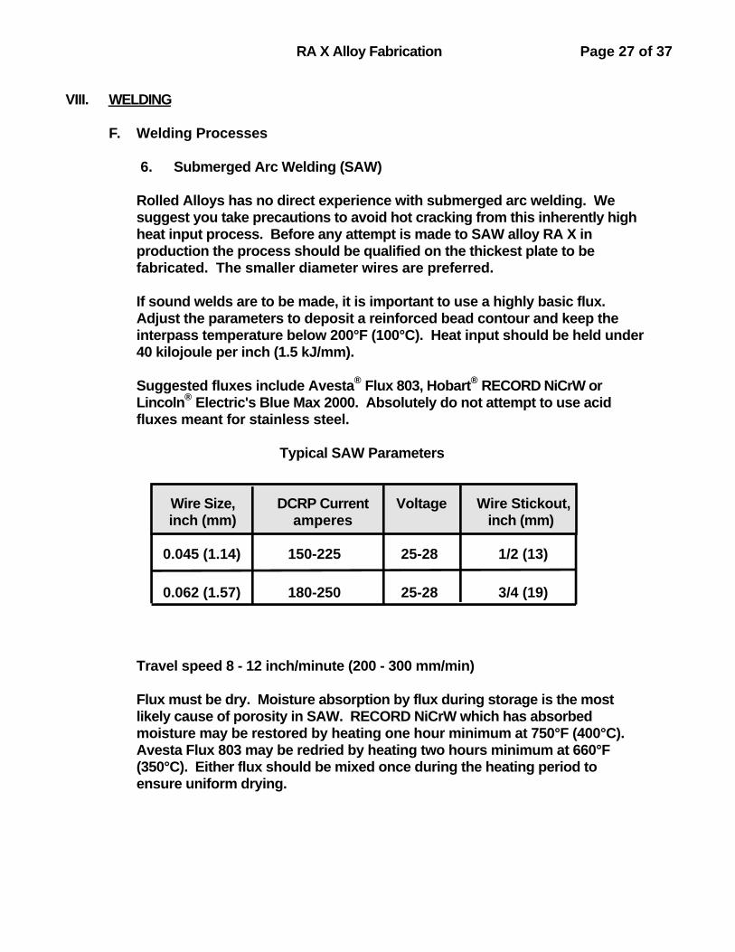
6. Submerged Arc Welding (SAW)
Rolled Alloys has no direct experience with submerged arc welding. We suggest you take precautions to avoid hot cracking from this inherently high heat input process. Before any attempt is made to SAW alloy RA X in production the process should be qualified on the thickest plate to be fabricated. The smaller diameter wires are preferred.
If sound welds are to be made, it is important to use a highly basic flux. Adjust the parameters to deposit a reinforced bead contour and keep the interpass temperature below 200°F (100°C). Heat input should be held under 40 kilojoule per inch (1.5 kJ/mm).
Suggested fluxes include Avesta® Flux 803, Hobart® RECORD NiCrW or Lincoln® Electric's Blue Max 2000. Absolutely do not attempt to use acid fluxes meant for stainless steel.
Typical SAW Parameters
Wire Size, DCRP Current Voltage Wire Stickout,inch (mm) amperes inch (mm)
0.045 (1.14) 150-225 25-28 1/2 (13)
0.062 (1.57) 180-250 25-28 3/4 (19)
Travel speed 8 - 12 inch/minute (200 - 300 mm/min)
Flux must be dry. Moisture absorption by flux during storage is the most likely cause of porosity in SAW. RECORD NiCrW which has absorbed moisture may be restored by heating one hour minimum at 750°F (400°C). Avesta Flux 803 may be redried by heating two hours minimum at 660°F (350°C). Either flux should be mixed once during the heating period to ensure uniform drying.

RA X Alloy Fabrication Page 28 of 37
VIII. WELDING
G. Dissimilar Metal Welds
Considerations in selecting a filler metal for dissimilar metal weld joints include the expected service conditions at the joint, relative thermal expansion coefficients and metallurgical compatibility of weld and base metal.
This suggested list of weld filler materials is based on welding knowledge and experience rather than laboratory work. Final selection should be approved by the end user and weld procedures qualified by the fabricator.
For Joining RA X to: Suggested Filler Metals
Carbon steel*; ferritic stainless steelssuch as 409, 439, or 446; austenitic-
ferritic duplex stainless steels such as2205, 2507, Ferralium® 255
RA 182 (ENiCrFe-3) covered electrodesHastelloy® S (AMS 5838) bare wire
RA82 (ERNiCr-3) bare wire
Austenitic stainless steels 304, 316, 321,347, 309, RA 253 MA® and 310; nickel
alloy RA330®
RA330-04-15 (UNS No. W88334) coveredelectrodes
RA330-04 (UNS No. N08334) bare wireRA X (ERNiCrMo-2, AMS 5798) bare wire
RA85H® Haynes® 556 (AMS 5831) bare wire
RA601 RA X bare wireRA333-70-16 (UNS No. W86333) covered
electrodesRA333 (UNS No. N06333) bare wire
RA600 RA 182 covered electrodesRA82 bare wire
RA X (AMS 5798) bare wire
RA 353 MA® RA 353 MA-15 covered electrodesRA 353 MA bare wire
RA X (AMS 5798) bare wire
RA625 RA112 (AWS ENiCrMo-3) covered electrodesRA625 (AWS ERNiCrMo-3, AMS 5837) bare
wireRA X (AMS 5799) covered electrodes
RA X (AMS 5798) bare wire
* Carbon steel MUST be ground to bright metal, or nickel alloy weld wire simply will not stick to it. A "mill finish" is not acceptable. All rust, blue-black hot rolling scale and paint must be removed before using nickel alloy weld fillers on carbon steel. Covered electrodes are somewhat more tolerant than bare wires, with respect to cleanliness.

RA X Alloy Fabrication Page 29 of 37
VIII. WELDING
G. Dissimilar Metal Welds, continued
For Joining RA X to: Suggested Filler Metals
RA333® RA333-70-16 covered electrodesRA333 bare wire
RA X (AMS 5798) bare wire
Cast heat resistant alloys HH, HK, HT, HP RA330-80-15 (UNS No. W88338)covered electrodes
Hastelloy® S (AMS 5838) bare wire
AL-6XN® RA 112 covered electrodesRA 625 bare wire
Alloys C-276, C-22, 59 C-22 (AWS ENiCrMo-10) coveredelectrodes
C-22 (AWS ERNiCrMo-10) bare wire
Haynes® 230, alloy 617 RA X (AMS 5798) bare wire230-W (AWS ERNiCrWMo-1) bare wire
Hastelloy S (AMS 5838) bare wire
Cobalt alloys L-605(alloy 25) and 188
Haynes 556 (AMS 5831) bare wireRA X (AMS 5798) bare wire
* RA718, X-750, Waspaloy®, René 41® Hastelloy S (AMS 5838) bare wireRA W (AMS 5786) bare wire
* These age hardening grades have fabrication characteristics completely outside the scope of this bulletin. Do become familiar with their welding requirements before making any weldment incorporating such alloys.

RA X Alloy Fabrication Page 30 of 37
VIII. WELDING
H. Controlling Distortion
RA X alloy has about 15% higher coefficient of thermal expansion than does carbon steel, but only about one fourth the thermal conductivity of steel. This combination naturally increases welding stresses and results in distortion in welded structures.
Heat treatment to relieve welding stresses in stainless or nickel alloys is usually ineffectual, impractical or downright harmful.
Proper fixturing, joint design, staggered weld bead placement or weld sequence and controlling heat input can all serve to minimize distortion.
The following are general suggestions:
2. Sequence
a. Tacks should be sequenced.
1 6 4 7 3 8 5 9 2
If the tacks are simply done in order from one end, the plate edges close up.
1 432 5
VIII. WELDING

RA X Alloy Fabrication Page 31 of 37
H. Controlling Distortion
2. Sequence
b. Weld runs should be done symmetrically about the joint's center of gravity to balance stresses +
1
2
3
4
5
6 7
8
10
9 11
12
double V - preparation
1
23
4
flange to cylinder
VIII. WELDING

RA X Alloy Fabrication Page 32 of 37
H. Controlling Distortion
3. Heat Balance +
Back step welding is helpful
3 2 1
* from Avesta Handbook for the Welding of Stainless Steel, Inf. 8901, Avesta Sheffield Welding AB, Avesta Sweden
+ from Sandvik Welding Handbook, by Berthold Lundqvist, Sandvik AB, Sandviken Sweden

RA X Alloy Fabrication Page 33 of 37
VIII. WELDING
H. Controlling Distortion
4. Heat Input
Heat into the workpiece is controlled by welding current, arc voltage, travel speed and the specific welding process used. For the same amps, volts and speed submerged arc welding (SAW) transfers the most heat, manual arc
(SMAW) and gas metal arc (GMAW) with argon next and roughly equivalent,while gas tungsten arc welding (GTAW) can put the least heat into the work.
Reducing heat input reduces the stresses and distortions from the welding operation.

RA X Alloy Fabrication Page 34 of 37
VIII. WELDING
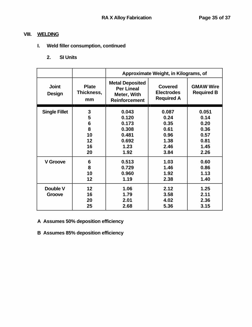
I. Weld Filler Consumption
Filler metal requirements range from about 2 - 1/2 to 5 percent of the weight of plate involved in a fabrication. Estimated weight of covered electrodes and
spooled wire for various joint configurations is given below.
1. U. S. Customary Units
APPROXIMATE WEIGHT, IN POUNDS, OF
JOINTDESIGN
PLATETHICKNESS,INCHES
METALDEPOSITED PERLINEAL FOOTWITHREINFORCEMENT
ELECTRODESREQUIRED(A)
GMAWWIREREQUIRED(B)
SINGLEFILLET
1/83/161/43/81/25/8
0.0320.0720.130.290.520.80
0.0640.1440.260.581.031.61
0.0380.0850.150.340.600.94
"V" GROOVE 1/43/81/2
0.370.620.85
0.731.231.7
0.430.731.00
DOUBLE "V"GROOVE
1/25/83/41
0.770.951.321.83
1.531.902.633.65
0.901.121.552.16
(A) Assumes 50% deposition efficiency
(B) Assumes 85% deposition efficiency
RA X Alloy Fabrication Page 35 of 37
VIII. WELDING
I. Weld filler consumption, continued
2. SI Units
Approximate Weight, in Kilograms, of
JointDesign
PlateThickness,
mm
Metal DepositedPer Lineal
Meter, WithReinforcement
Covered
ElectrodesRequired A
GMAW WireRequired B
Single Fillet 356810121620
0.0430.1200.1730.3080.4810.6921.231.92
0.0870.240.350.610.961.382.463.84
0.0510.140.200.360.570.811.452.26
V Groove 681012
0.5130.7290.9601.19
1.031.461.922.38
0.600.861.131.40
Double VGroove
12162025
1.061.792.012.68
2.123.584.025.36
1.252.112.363.15
A Assumes 50% deposition efficiency
B Assumes 85% deposition efficiency

RA X Alloy Fabrication Page 36 of 37
IX. BRAZING
RA X components for gas turbine engines are commonly joined by brazing with nickel alloy filler metals.
Some items to consider are:
Cleanliness Not only oxide scales but all traces of grease, oil, marking pencil or residual dye or fluorescent penetrant inspection fluids must be removed, or they may interfere with braze flow.
Atmosphere Vacuum or dry hydrogen, dew point -60°F (-51°C) or lower, are used. Graphite fixturing in hydrogen atmospheres may transfer carbon to the work unless protected.
Joint fit-up Suggested joint gaps are the gaps AT TEMPERATURE. When brazing dissimilar metals take into account thermal expansion
coefficients when calculating gap at the brazing temperature.
Repair cycles With nickel-silicon-boron braze fillers diffusion into the base metal raises the subsequent remelt temperature of the joint.

RA X Alloy Fabrication Page 37 of 37
IX. BRAZING, continued
Some commonly used high temperature braze filler metals for RA X include:
Trade or Brazing SuggestedSpecifications Common RangeBraze Temp Joint GapAMS AWS Name ºF ºC ºF ºC inch mm
4787 BAu-4 Permabraze® 130 1745 950 1800 980 0.0015 0.0482Au-18Ni 1850 1010 minimum 0.003 0.08
4777 BNi-2 Nicrobraz® L.M. 1850 1010 1900 1040 0.001 0.025Coast Metal® 53 2150 1175 0.004 0.10MBF 20*
4778 BNi-3 Nicrobraz 130 1850 1010 1900 1040 from contact to:Coast Metal 52 2150 1175 0.002 0.05MBF 30
4779 BNi-4 Nicrobraz 135 1950 1065 2050 1120 0.002 0.05Coast Metal 50 2150 1175 0.004 0.10
4782 BNi-5 Nicrobraz 30 2100 1150 2175 1190 0.001 0.0252200 1205 0.004 0.10
* METGLAS® Brazing Foil

SUGGESTED READING
RA X data and other fabrication information available from Rolled Alloys include:
Bulletin No Title Pages
152 Aircraft and Aerospace Heat Resistant Alloys 17
201 Welding RA330 12
203 Fabrication Procedures for Rolled AlloysAL-6XN® 58
205 RA320LR Welding Materials 2
207 RA330® Heat Resistant AlloyFabrication 42
208 RA85H® Heat Resistant Alloy Fabrication 27
209 RA 353 MA® Fabrication 8
General heat resistant alloy welding information is available in:
R. J. Castro & J. J. deCadenet, "Welding Metallurgy of Stainless and Heat-ResistingSteels," ISBN 0 521 20431 3, Cambridge University Press 1975.
"Welding Dissimilar Metals" ed. N. Bailey, The Welding Institute, 1986.
T. G. Gooch "Solidification Cracking of Austenitic Stainless Steel" pp 31-40Weldability of Materials, ed. R. A. Patterson and K. W. Mahin, ISBN: 0-87170-401-3ASM International 1990.
"Arc Welding of Nickel Alloys" pp 436-445, Metals Handbook Ninth Edition Volume 6Welding, Brazing and Soldering, ASM International.
Resistance Welding Manual, available from Resistance Welder Manufacturers'Association, 1900 Arch Street, Philadelphia Pennsylvania 19103 FAX 215-564-2175
S. J. Matthews, M. O. Maddock & W. F. Savage "How Copper Surface ContaminationAffects Weldability of Cobalt Superalloys," Welding Journal, May 1972.
E. F. Nippes & D. J. Ball "Copper-Contamination Cracking: Cracking Mechanism &Crack Inhibitors," pp 75S-81S, Welding Research Supplement March 1982.
William G. Ashbaugh "Liquid Metal Embrittlement-Part II" pp 88-89, MaterialsPerformance February 1993.

TRADEMARKS
Avesta®, 253 MA® and 353 MA® are registered trademarks of Avesta Sheffield Inc.
METGLAS® is a registered trademark of Allied Signal Inc.
René® is a registered trademark of GE Company
Haynes® and Hastelloy® are registered trademarks, and 230-W a trademark, ofHaynes International.
Ferralium® is a registered trademark of Langley Alloys, Ltd.
Permabraze® is a registered trademark of Hardy & Harman.
Hobart® is a registered trademark of Hobart Brothers Co.
Kolene® is a registered trademark of Kolene Corporation.
Lenox® is a registered trademark of American Saw & Mfg. Company
Lincoln® is a registered trademark of The Lincoln Electric Co.
Waspaloy® is a registered trademark of Special Metals Corp.
Nicrobraz® is a registered trademark of Wall Colmonoy Corp.
INDEX
Age hardening.........................................................................................................................................................................29Aluminum.....................................................................................................................................................................................15Amperage.................................................................................................................................................................22, 23, 26AMS..........................................................................................................................................................................3, 14, 21, 37Argon...................................................................................................................................................5, 16, 23, 24, 25, 33ASME....................................................................................................................................................................................3, 4, 16ASTM..........................................................................................................................................................................................3, 16AWS................................................................................................................................................................................14, 21, 37
Bead contour.........................................................................................................................................................12, 24, 27Bending.............................................................................................................................................................................................8Braze.................................................................................................................................................................................3, 36, 37Butt joint.........................................................................................................................................................................................17
Carbon steel........................................................................................................................................13, 15, 16, 28, 30Carburizing, carbon....................................................................................................................................................1, 36Caustic............................................................................................................................................................................................11Chloride.............................................................................................................................................................................................1CO2......................................................................................................................................................................................................24Copper.............................................................................................................................................................................................15Corrosion..............................................................................................................................................................................1, 21Cracking...........................................................................................................................8, 9, 12, 13, 15, 17, 24, 27Crater...............................................................................................................................................................................................12Current.........................................................................................................................................................................21, 22, 23Cutting...................................................................................................................................................................................5, 6, 7
Descale..........................................................................................................................................................................................11Dissimilar metal.................................................................................................................................................28, 29, 36Distortion.........................................................................................................................................................30, 31, 32, 33
Ferrite...............................................................................................................................................................................................12Flux............................................................................................................................................................................................21, 27Forging...............................................................................................................................................................................................9
GE specifications....................................................................................................................................................................3GMAW.................................................................................................................................................................21, 24, 25, 31GTAW.............................................................................................................................................................................21, 23, 31
Heat input........................................................................................................................................................13, 27, 30, 33Helium...........................................................................................................................................................................23, 24, 25Hydrofluoric...............................................................................................................................................................................11Hydrogen...............................................................................................................................................................................5, 36
Inspect..................................................................................................................................................................................16, 36
J-groove........................................................................................................................................................................................20Lead...................................................................................................................................................................................................15

Machining.................................................................................................................................................................................6, 7Moisture.....................................................................................................................................................................21, 22, 27Molybdenum................................................................................................................................................................................1
Nitric..................................................................................................................................................................................................11Nitrogen..................................................................................................................................................................................5, 23
O2..........................................................................................................................................................................................................24Orange peel...............................................................................................................................................................................10Oxidation...................................................................................................................................................................................1, 9
Penetration..............................................................................................................................................................15, 16, 20Plasma............................................................................................................................................................................5, 16, 26Porosity.......................................................................................................................................................................21, 22, 26Preheat...........................................................................................................................................................................................13(PRE) N...............................................................................................................................................................................................1
Root Pass.....................................................................................................................................................................................16
Salt......................................................................................................................................................................................................11Sawing...............................................................................................................................................................................................6Shielding gases..................................................................................................................................................23, 24, 25SMAW....................................................................................................................................................................................21, 31Spot welding.............................................................................................................................................................................26Stainless....................................................................................................................................................................15, 27, 28Stress relief...............................................................................................................................................................................10Submerged arc...........................................................................................................................................................21, 27
T-joint................................................................................................................................................................................................20Tack welds.................................................................................................................................................................................30Thermal conductivity..........................................................................................................................................2, 9, 30Thermal expansion........................................................................................................................2, 19, 28, 30, 36
U-joint...............................................................................................................................................................................................19
V-joint.....................................................................................................................................................................................18, 31
Weld fillers.........................................................................................................1, 12, 14, 19, 20, 28, 29, 34, 35
Zinc.....................................................................................................................................................................................................15