Quickstart: TPCS-4SM & TPCS-4SMD - DEKOM · PDF filequickstart guide TPCS-4SM & TPCS-4SMD ......
4
quickstart guide TPCS-4SM & TPCS-4SMD www.crestron.com 888.273.7876 201.767.3400 Specifications subject to change without notice. TPCS-4SM & TPCS-4SMD 4.3” Touch Screen Control Systems The Crestron ® TPCS-4SM and TPCS-4SMD ship with 10 “hard key” push buttons for quick access to commonly used functions. Optional, custom engravable button covers are available (4SM-BTNO-[B, W]-S and custom engraving sold separately). For a clean appearance, either column of buttons may be removed and covered using the no-button covers provided. To change the inserts or covers, use the following procedure: 1. Insert a small, slot head screwdriver into the appropriate hole on the bottom of the touch screen to release its cover. Refer to the following illustration. 1 Change the Button Inserts or Button Covers QUICKSTART DOC. 7230D (2032259, Sheet 1 of 2) 05.13 1 Mounting in a US Electrical Box 2 Install the Touch Screen 2. With the bottom of the cover released, gently remove it from the touch screen. 3. If removing the button insert, after releasing and removing the button cover, use a small slot head screwdriver to press and gently lift the button insert from the touch screen. Refer to the following illustration for the press and lift points on the button insert. 4. Gently place the new cover in position and press it into place. 2. Use the two included #06-32 x 1 x 1/2” screws (2007254) to attach the back panel to a horizontally mounted electrical box, as shown in the following illustration. Mounting the Touch Screen into an Electrical Box Snap the Touch Screen into Place 3. Carefully position the front of the touch screen over the back panel and gently snap it into place, as shown in the following illustration. 4. Use two of the included #04-40 x 1/4” screws to secure the touch screen, as shown in the following illustration: a. For standard applications, use the Phillips screws (2007152 or 2007160). b. For secure applications, use the security type Torx screws (2025311 or 2025312) along with the included Torx screwdriver bit (2025915). NOTE: If using the touch screen with a C2N-IO Control Port Expansion Module, install the C2N-IO in the electrical box using the fastener included with the module. For details, refer to the latest version of the C2N-IO Operations & Installation Guide (Doc. 7236). It is available from the Crestron Web site (www.crestron.com/manuals). Insert screwdriver to release covers Use screwdriver to release button insert Insert screwdriver to separate back of touch screen Screws (2) #06-32 x 1 1/2” (2007254) Horizontally mounted electrical box NOTE: When mounting the TPCS-4SM or TPCS-4SMD into an electrical box, the box must be installed horizontally. The TPCS-4SM and TPCS-4SMD touch screens install simply and easily into a standard electrical box or onto virtually any flat surface. A tabletop enclosure, the TTS-4SM and swivel mount, SMK-4SM are also available (both sold separately). For mounting onto a flat surface, use the MSMK-4SM Multi-Surface Mounting Kit (sold separately). The TPCS-4SM and TPCS-4SMD are supplied with screws for installation into an electrical box. To mount the TPCS-4SM or TPCS-4SMD into an electrical box, use the following procedure: 1. Insert a small slot head screwdriver into the hole shown in the following illustration and gently separate the back of the touch screen. Insertion Point for Separation of Back Panel Insertion Points for Button Cover Releases Touch Screen with Button Inserts Touch Screen with No-Button Covers NOTE: Use the left and right screw holes for attachment to the electrical box. For Regulatory Compliance information, refer to the latest version of Doc. 7229.
Transcript of Quickstart: TPCS-4SM & TPCS-4SMD - DEKOM · PDF filequickstart guide TPCS-4SM & TPCS-4SMD ......
qu
icksta
rt g
uid
e
TPCS-4SM & TPCS-4SMD
www.crestron.com 888.273.7876 201.767.3400 Specifications subject to change without notice.
TP
CS
-4S
M &
TP
CS
-4S
MD
4.3” Touch Screen Control Systems
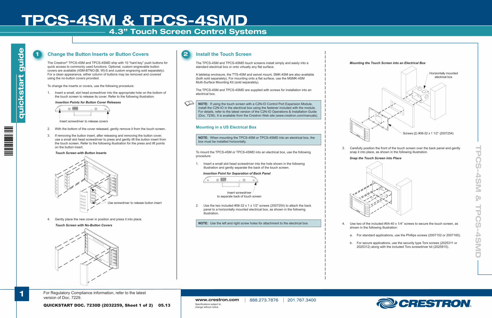
The Crestron® TPCS-4SM and TPCS-4SMD ship with 10 “hard key” push buttons for quick access to commonly used functions. Optional, custom engravable button covers are available (4SM-BTNO-[B, W]-S and custom engraving sold separately). For a clean appearance, either column of buttons may be removed and covered using the no-button covers provided.
To change the inserts or covers, use the following procedure: 1. Insert a small, slot head screwdriver into the appropriate hole on the bottom of the touch screen to release its cover. Refer to the following illustration.
1 Change the Button Inserts or Button Covers
QUICKSTART DOC. 7230D (2032259, Sheet 1 of 2) 05.13
1
Mounting in a US Electrical Box
2 Install the Touch Screen
2. With the bottom of the cover released, gently remove it from the touch screen. 3. If removing the button insert, after releasing and removing the button cover, use a small slot head screwdriver to press and gently lift the button insert from the touch screen. Refer to the following illustration for the press and lift points on the button insert.
4. Gently place the new cover in position and press it into place.
2. Use the two included #06-32 x 1 x 1/2” screws (2007254) to attach the back panel to a horizontally mounted electrical box, as shown in the following illustration.
Mounting the Touch Screen into an Electrical Box
Snap the Touch Screen into Place
3. Carefully position the front of the touch screen over the back panel and gently snap it into place, as shown in the following illustration.
4. Use two of the included #04-40 x 1/4” screws to secure the touch screen, as shown in the following illustration:
a. For standard applications, use the Phillips screws (2007152 or 2007160).
b. For secure applications, use the security type Torx screws (2025311 or 2025312) along with the included Torx screwdriver bit (2025915).
NOTE: If using the touch screen with a C2N-IO Control Port Expansion Module, install the C2N-IO in the electrical box using the fastener included with the module. For details, refer to the latest version of the C2N-IO Operations & Installation Guide (Doc. 7236). It is available from the Crestron Web site (www.crestron.com/manuals).
Insert screwdriver to release covers
Use screwdriver to release button insert
Insert screwdriverto separate back of touch screen
Screws (2) #06-32 x 1 1/2” (2007254)
Horizontally mountedelectrical box
NOTE: When mounting the TPCS-4SM or TPCS-4SMD into an electrical box, the box must be installed horizontally.
The TPCS-4SM and TPCS-4SMD touch screens install simply and easily into a standard electrical box or onto virtually any flat surface.
A tabletop enclosure, the TTS-4SM and swivel mount, SMK-4SM are also available (both sold separately). For mounting onto a flat surface, use the MSMK-4SM Multi-Surface Mounting Kit (sold separately).
The TPCS-4SM and TPCS-4SMD are supplied with screws for installation into an electrical box.
To mount the TPCS-4SM or TPCS-4SMD into an electrical box, use the following procedure:
1. Insert a small slot head screwdriver into the hole shown in the following illustration and gently separate the back of the touch screen.
Insertion Point for Separation of Back Panel
Insertion Points for Button Cover Releases
Touch Screen with Button Inserts
Touch Screen with No-Button Covers NOTE: Use the left and right screw holes for attachment to the electrical box.
For Regulatory Compliance information, refer to the latest version of Doc. 7229.

qu
icksta
rt g
uid
e
TPCS-4SM & TPCS-4SMD
www.crestron.com 888.273.7876 201.767.3400 Specifications subject to change without notice.
TP
CS
-4S
M &
TP
CS
-4S
MD
4.3” Touch Screen Control Systems
QUICKSTART DOC. 7230D (2032259, Sheet 1 of 2) 05.13
2
2 Install the Touch Screen (Continued)
Mounting the Touch Screen into a European Electrical Box
Mounting in a European Electrical Box
Ethernet Communication
4 Establish Communication Use Crestron Toolbox™ for communicating with the TPCS-4SM and TPCS-4SMD; refer to the Crestron Toolbox help file for details. There is a single method of communication: TCP/IP communication.
Make the necessary connections as called out in the illustration below.Apply power after all connections have been made.
When making connections to the TPCS-4SM or TPCS-4SMD, use Crestron power supplies for Crestron equipment.
3 Hardware Hookup
* When used with a C2N-IO Control Port Expansion Module, connect to one of its NET ports.
Hardware Connections for the TPCS-4SM or TPCS-4SMD
Screws (2) #4B x 3/4” (2019088)
Screws ( 2 ) # 04 - 40 x 1 / 4 ”
For standard applications : Phillips ( 2007152 or 2007160 )
For secure applications : security type Torx ( 2025311 or 2025312 )
Secure the Touch Screen
To mount the TPCS-4SM or TPCS-4SMD into a European electrical box, use the following procedure:
1. Insert a small slot head screwdriver into the hold shown in the illustration in step 1, in the middle column on the previous page, to gently separate the back of the touch screen.
2. Use the two included #4B x 3/4” screws (2019088) to attach the back panel to the electrical box, as shown in the following illustration.
NOTE: For European electrical boxes, use the top and bottom screw holes for attachment to the electrical box.
3. Carefully position the front of the touch screen over the back panel and gently snap it into place, as shown in the illustration in step 3, in the last column on the previous page.
4. Use two of the included #04-40 x 1/4” screws to secure the touch screen, as shown in the illustration at the top of the column to the left:
a. For standard applications, use the Phillips screws (2007152 or 2007160).
b. For secure applications, use the security type Torx screws (2025311 or 2025312) along with the included Torx screwdriver bit (2025915).
LAN PoE : 10 BASE - T / 100 BASE - TX
Ethernet to LAN
NET : To any Cresnet ®
Network Device *
NOTE: To prevent overheating, do not operate this product in an area that exceeds the environmental temperature range listed in the table of specifications. Refer to section “Specifications” on page 4 for details.�
For Regulatory Compliance information, refer to the latest version of Doc. 7229.
PC RunningCrestron Toolbox
LAN
PowerInjector
CRESTRON
CEN-SW-POE-5
Power over Ethernet Switch
Uplink
PoE
1
2
3
4
48VDC
Power
120 Volts
POE
TPCS-4SM(D)
The TPCS-4SM or TPCS-4SMD connects to PC via Ethernet:
1. Use the Device Discovery Tool (click the icon) in Crestron Toolbox to detect all Ethernet devices on the network and their IP configuration. The tool is available in Toolbox version 1.15.143 or later.
2. Click on the TPCS-4SM or TPCS-4SMD to display information about the device.

qu
icksta
rt g
uid
e
TPCS-4SM & TPCS-4SMD
www.crestron.com 888.273.7876 201.767.3400 Specifications subject to change without notice.
TP
CS
-4S
M &
TP
CS
-4S
MD
4.3” Touch Screen Control Systems
QUICKSTART DOC. 7230D (2032259, Sheet 2 of 2) 05.13
3
7 Pinout Reference
The TPCS-4SM and TPCS-4SMD have the following ports.
NOTE: During regular operation of the touch screen, there are two ways to activate the setup functions: 1. Place a button on the project main page and assign the reserved join number (17242) that activates setup. 2. Press hard keys 1, 2, 3 and 4, on the left side of the touch screen display (the top four of the five buttons), in sequence twice (press 1, 2, 3, 4, 1, 2, 3, 4) within a 5 second period.
The main “Setup” menu is the starting point for configuration of the TPCS-4SM or TPCS-4SMD. To enter the “Setup” menu, touch the screen while applying power to the unit.
5 Configure the Touch Screen
Touch the Setup button to display the TPCS-4SM or TPCS-4SMD main “Setup” menu, as shown in the illustration below. The setup menus enable basic configuration procedures prior to regular operation of the touch screen.
NOTE: For details on configuring the TPCS-4SM and TPCS-4SMD, refer to the latest version of the TPCS-4SM & TPCS-4SMD Configuration Guide (Doc. 7332).
* The pinout table indicates signal connections. dc power applied by Ethernet power sourcing equipment (PSE) can connect to either signal pins or N/C pins.
NOTE: The TPCS-4SM and TPCS-4SMD can take up to 45 seconds to boot to a display after initial power up.
6 Dimensions TPCS-4SM and TPCS-4SMD Overall Dimensions (Front, Bottom and Rear Views, TPCS-4SM Shown)
6 . 20 in ( 158 mm )
3 . 47 in ( 89 mm )
0 . 46 in ( 12 mm )
0 . 75 in ( 19 mm )
1 . 21 in ( 31 mm )
2 . 00 in ( 51 mm )
3 . 25 in ( 83 mm )
1 . 70 in ( 44 mm )
2 . 36 in ( 60 mm )
24 Y Z G
NET
PIN DESCRIPTION 24 Y Z G
Power ( 24 Volts DC ) Data Data
Ground
Green LED
Yellow LED
Pin 8 Pin 1
LAN PoE*
PIN DESCRIPTION 1 2 3 4 5 6 7 8
TX + TX - RX +
N / C N / C RX -
N / C N / C
NOTE: The only connection required to configure the touch screen is power. Refer to section “Hardware Hookup” on page 2 for details.�
For Regulatory Compliance information, refer to the latest version of Doc. 7229.

qu
icksta
rt g
uid
e
TPCS-4SM & TPCS-4SMD
www.crestron.com 888.273.7876 201.767.3400 Specifications subject to change without notice.
TP
CS
-4S
M &
TP
CS
-4S
MD
4.3” Touch Screen Control Systems
8 Specifications
QUICKSTART DOC. 7230D (2032259, Sheet 2 of 2) 05.13
4
The specific patents that cover Crestron products are listed at patents.crestron.com.
Crestron, the Crestron logo, Cresnet, Crestron Fusion, Crestron Mobile, Crestron Toolbox, Fusion RV, infiNET EX, RoomView and Smart Graphics are either trademarks or registered trademarks of Crestron Electronics, Inc. in the United States and/or other countries. Internet Explorer, Microsoft and Windows are either trademarks or registered trademarks of Microsoft Corporation in the United States and/or other countries. Other trademarks, registered trademarks and trade names may be used in this document to refer to either the entities claiming the marks and names or their products. Crestron disclaims any proprietary interest in the marks and names of others. Crestron is not responsible for errors in typography or photography.
This document was written by the Technical Publications department at Crestron.©2013 Crestron Electronics, Inc.
Connectors LAN PoE: (1) 8-wire RJ-45 with two LED indicators 10BASE-T/100BASE-TX Ethernet port, Power over Ethernet compliant Green and yellow LEDs indicate Ethernet port status NET: (4) captive screw terminals Cresnet master port Connects to C2N-IO Control Port Expansion Module and other Cresnet devices (all sold separately)1 Power Requirements Power over Ethernet: IEEE 802.3af (802.3at Type 1) Class 3 PoE Powered Device Available Cresnet Power: 4 watts (167 mA @ 24 Vdc) Environmental Temperature: 32° to 104° F (0° to 40° C) Humidity: 10% to 90% RH (non-condensing) Heat Dissipation: 14 Btu/h Enclosure Construction: Plastic, black or white, smooth finish Front Bezel: Plastic, hard buttons installed with unlabeled button covers, custom engraving sold separately, “no-button” covers also included Mounting: Requires a horizontally oriented 1-gang electrical box or plaster ring or a 1-Gang European (DIN 49073) electrical box; choice of standard or security screws provided; optional universal wall, multi-surface and table top mounting kits sold separately Dimensions Height: 3.47 in (89 mm) Width: 6.20 in (158 mm) Depth: 1.21 in (31 mm) Weight 9 oz (249 g) NOTES
1. Supports a maximum of 10 Ethernet devices, 10 Cresnet devices, one infiNET EX® wireless gateway and one Crestron Mobile device
2. License required. Supports a maximum of 250 BACnet objects when dedicated for BACnet use only. Actual capabilities are contingent upon the overall program size and complexity.
3. Web based installer setup requires Microsoft® Internet Explorer® Web browser running on a Windows® PC.
Control Engine 3-Series™; real time, preemptive multithreaded/multitasking kernel; Transaction-Safe Extended FAT file system1 Graphics Engine Supports Smart Graphics™ Memory SDRAM: 256 MB Flash: 2 GB Maximum Touch Screen Project Size: 60 MB Communications Ethernet: 10/100 Mbps; auto-switching; auto-negotiating; auto-discovery; full/half duplex; industry-standard TCP/IP stack; UDP/IP; CIP; DHCP; SSL; IEEE 802.1X; SNMP; BACnet®/IP2; IPv4 or IPv6; Active Directory authentication; IIS v.6.0 Web Server; SMTP e-mail client; installer setup via Crestron Toolbox or MSIE3; supports all XPanel, Crestron Mobile®, Crestron Fusion™ and RoomView® applications, IEEE 802.3af and 802.3at Type 1 compliant Model TPCS-4SM, also features Fusion RV™ Room Scheduling mode Cresnet: Cresnet® master mode Audio Audio Feedback Format: MP3 Touch Screen Display Display Type: TFT Active matrix color LCD Size: 4.3 inch (109 mm) diagonal Aspect Ratio: 16:9 WVGA Resolution: 800 x 480 pixels Brightness: 270 nits (cd/m2) Contrast: 300:1 Color Depth: 16-bit, 64k colors Illumination: Backlit LED Viewing Angle: ±80° horizontal, ±80° vertical Touch Screen: Resistive membrane Buttons Hard Keys: (10) Optional programmable push buttons, translucent backlit Feedback/Backlight:
TPCS-4SM: (1) red and (1) green LED per hard key, programmable for feedback and backlighting TPCS-4SMD: (1) white LED per hard key, programmable for feedback and backlighting Reset: (1) Recessed push button behind pinhole for hardware reset Proximity Sensor Type: Active infrared beam and receiver Range: 3-4 feet Wakes the touch screen and backlight
For Regulatory Compliance information, refer to the latest version of Doc. 7229.