Operation Power Meter 3 SIMEAS P 7KG7750/55...
134
E50417-B1076-C340-A4 Power Meter SIMEAS P 7KG7750/55 Manual Foreword, Contents Commissioning 1 Operation 2 Measured Quantities 3 Device Parameterization 4 Parameterization via PC Software 5 Calibration 6 Technical Data 7
Transcript of Operation Power Meter 3 SIMEAS P 7KG7750/55...
E50417-B1076-C340-A4
Power Meter
SIMEAS P 7KG7750/55
Manual
Foreword, Contents
Commissioning 1Operation 2Measured Quantities 3Device Parameterization 4Parameterization via PC Software 5Calibration 6Technical Data 7

Note
Please observe the instructions and warnings for your safety in the foreword.
Siemens Aktiengesellschaft Order No.: E50417-B1076-C340-A4
Disclaimer of LiabilityWe have checked the contents of this document and every effort has been made to ensure that the descriptions of both hardware and software are as accurate as possible. However, since devia-tions cannot be ruled out entirely, we do not accept liability for com-plete conformity or for any errors or omissions. The information in this manual is checked periodically, and neces-sary corrections will be included in future editions. We are grateful for any improvements that you care to suggest.
Subject to technical alterations. Document Release V01.11.02Edition 05.2011
CopyrightCopyright © Siemens AG 2011 This document shall not be transmitted or reproduced, nor shall its contents be exploited or disclosed to third parties without prior writ-ten consent from Siemens. Offenders will be liable for damages. All rights, including rights created by patent grant or registration of a utility model or design, are reserved. Registered TrademarksSIPROTEC®, DIGSI®, OSCOP® and SIMEAS® are registered trademarks of SIEMENS AG. Other designations in this manual might be trademarks whose use by third parties for their own purposes would infringe the rights of the owner.
Foreword
Purpose of the manualThis manual describes the commissioning, operation and parameterization of the Power Meter SIMEAS P 7KG7750/55.
Target audienceThis manual is directed to the user of the Power Meter SIMEAS P.
Validity of the manualThis manual is valid for the devices SIMEAS P 7KG7750/55.
Additional supportFor any questions concerning your system, please contact your local Siemens representative.
HotlineOur Customer Support Center provides around-the-clock service.
Phone: +49 180 5 247000
Fax: +49 180 5 242471
E-mail: [email protected]
Internet: http://www.powerquality.de/pq_da/index_e.htm
FAQ: http://www.siemens.com/energy-support/faq-en
Further documentsSIMEAS P Power Meter 7KG775x Operating Instructions
Ordering no. E50417-B1074-C339
SIMEAS P PROFIBUS DP Manual
Ordering no. E50417-B1076-C238
Power Meter SIMEAS P Modbus Manual
Ordering no. E50417-B1076-C241
Power Meter SIMEAS P 7KG7750/55 Communication Protocol IEC 60870-5-103 Manual
Ordering no. E50417-B1076-C375
3Power Meter, SIMEAS P 7KG7750/55, ManualE50417-B1076-C340-A4, Edition 05.2011

Foreword
Training coursesPlease ask our Training Center for information on the individual courses available:
Siemens AG
Power Transmission and DistributionPower Training Center
Humboldtstr. 5990459 Nuremberg
Germany
Phone: +49 911 433-7005
Fax: +49 911 433-7929
Internet: www.ptd-training.com
4 Power Meter, SIMEAS P 7KG7750/55, ManualE50417-B1076-C340-A4, Edition 05.2011

Foreword
Information for your safetyThis manual does not represent a complete listing of all the safety measures required to operate the equipment (module, device) since specific operating conditions may make further measures necessary. However, it contains information which you have to observe in order to ensure your personal safety and in order to avoid material damage. The information is highlighted by a warn-ing triangle and, depending on the degree of danger, is shown as follows:
DANGERDANGER means that death or severe injury will result if the measures specified are not taken.
• Comply with all instructions, in order to avoid death or severe injuries.
WARNINGWARNING means that death or severe injury may result if the measures specified are not taken.
• Comply with all instructions, in order to avoid death or severe injuries.
CAUTIONCAUTION means that minor or moderate injury can occur if the measures specified are not taken.
• Comply with all instructions, in order to avoid moderate or minor injuries.
NOTICENOTICE means that property damage can result if the measures specified are not taken.
• Comply with all instructions, in order to avoid material damage.
NoteImportant information about the product, product handling or a certain section of the documen-tation, which must be given particular attention.
Qualified personnelCommissioning and operation of the equipment (module, device) described in this manual must be performed by qualified personnel only. As used in the safety notes contained in this manual, qualified personnel are those persons who are authorized to commission, release, ground, and tag devices, systems and electrical circuits in accordance with the safety standards.
Use as prescribedThe equipment (device, module) must not be used for any other purposes than those described in the Catalogue and the Technical Description. If it is used together with third party devices and components, these must be recommended or approved by Siemens.
Correct and safe operation of the product requires adequate transportation, storage, installation, and mounting as well as appropriate use and maintenance.
During operation of electrical equipment, it is unavoidable that certain parts of this equipment will carry dangerous voltages. Severe injury or damage to property can occur if the appropriate measures are not taken:
• Before making any connections at all, ground the equipment at the PE terminal.
• Hazardous voltages can be present on all switching components connected to the power supply.
• Even after the supply voltage has been disconnected, hazardous voltages can still be present in the equipment (capacitor storage).
• Equipment with current transformer circuits must not be operated while open.
• The limit values indicated in the manual must not be exceeded; that also applies to testing and commissioning.
5Power Meter, SIMEAS P 7KG7750/55, ManualE50417-B1076-C340-A4, Edition 05.2011

Foreword
Statemant of Conformity
This product complies with the directive of the Council of the European Communities on the approximation of the laws of the member states relating to electromagnetic compatibility (EMC Council Directive 2004/108/EC) and concerning electrical equipment for use within specified voltage limits (Low Voltage Directive 2006/95/EC).
This conformity has been proved by tests performed according to the Council Directives in agreement with the generic standards EN 61000-6-2 and EN 61000-6-4 (for EMC Directive) and with the standard EN 61010-1 (for Low Voltage Directive) by Siemens AG.
This device was designed and produced for industrial use according to the standard EN 61000-6-4.
The product conforms to the standards IEC 60688, EN 60688 or DIN EN 60688.
6 Power Meter, SIMEAS P 7KG7750/55, ManualE50417-B1076-C340-A4, Edition 05.2011

Contents
Contents
1 Commissioning . . . . . . . . . . . . . . . . . . . . . . . . . . . . . . . . . . . . . . . . . . . . . . . . . . . . . . . . . . . 11
1.1 Delivery . . . . . . . . . . . . . . . . . . . . . . . . . . . . . . . . . . . . . . . . . . . . . . . . . . . . . . . . . . 12
1.2 Ordering Data . . . . . . . . . . . . . . . . . . . . . . . . . . . . . . . . . . . . . . . . . . . . . . . . . . . . . 131.2.1 SIMEAS P 7KG7750 . . . . . . . . . . . . . . . . . . . . . . . . . . . . . . . . . . . . . . . . . . . . . 131.2.2 SIMEAS P 7KG7755 . . . . . . . . . . . . . . . . . . . . . . . . . . . . . . . . . . . . . . . . . . . . . 141.2.3 Parameterization Package. . . . . . . . . . . . . . . . . . . . . . . . . . . . . . . . . . . . . . . . . 14
1.3 Dimensions . . . . . . . . . . . . . . . . . . . . . . . . . . . . . . . . . . . . . . . . . . . . . . . . . . . . . . . 151.3.1 Device Variant SIMEAS P 7KG7750 . . . . . . . . . . . . . . . . . . . . . . . . . . . . . . . . . 151.3.2 Device Variant SIMEAS P 7KG7755 . . . . . . . . . . . . . . . . . . . . . . . . . . . . . . . . . 18
1.4 Block Diagram . . . . . . . . . . . . . . . . . . . . . . . . . . . . . . . . . . . . . . . . . . . . . . . . . . . . . 19
1.5 Interface and Terminals. . . . . . . . . . . . . . . . . . . . . . . . . . . . . . . . . . . . . . . . . . . . . . 211.5.1 Terminal Assignment SIMEAS P 7KG7750/55 . . . . . . . . . . . . . . . . . . . . . . . . . 211.5.2 Terminal Assignment . . . . . . . . . . . . . . . . . . . . . . . . . . . . . . . . . . . . . . . . . . . . . 221.5.3 Assignment of the Interface . . . . . . . . . . . . . . . . . . . . . . . . . . . . . . . . . . . . . . . . 241.5.4 Connection Examples . . . . . . . . . . . . . . . . . . . . . . . . . . . . . . . . . . . . . . . . . . . . 251.5.4.1 General . . . . . . . . . . . . . . . . . . . . . . . . . . . . . . . . . . . . . . . . . . . . . . . . . . . . 251.5.4.2 Single-phase . . . . . . . . . . . . . . . . . . . . . . . . . . . . . . . . . . . . . . . . . . . . . . . . 251.5.4.3 Three-phase, Three-wire, Balanced. . . . . . . . . . . . . . . . . . . . . . . . . . . . . . . 261.5.4.4 Three-phase, Three-wire, Unbalanced ( 2 I, Aron Circuit) . . . . . . . . . . . . . . 261.5.4.5 Three-phase, Four-wire, Balanced. . . . . . . . . . . . . . . . . . . . . . . . . . . . . . . . 271.5.4.6 Three-phase, Four-wire, Unbalanced (Low-voltage System). . . . . . . . . . . . 271.5.4.7 Three-phase, Four-wire, Unbalanced (High-voltage System) . . . . . . . . . . . 271.5.5 Commissioning . . . . . . . . . . . . . . . . . . . . . . . . . . . . . . . . . . . . . . . . . . . . . . . . . 281.5.6 Electrical Connection . . . . . . . . . . . . . . . . . . . . . . . . . . . . . . . . . . . . . . . . . . . . . 28
2 Operation . . . . . . . . . . . . . . . . . . . . . . . . . . . . . . . . . . . . . . . . . . . . . . . . . . . . . . . . . . . . . . . . 31
2.1 Screen Display . . . . . . . . . . . . . . . . . . . . . . . . . . . . . . . . . . . . . . . . . . . . . . . . . . . . 32
2.2 Screen Content . . . . . . . . . . . . . . . . . . . . . . . . . . . . . . . . . . . . . . . . . . . . . . . . . . . . 322.2.1 Screen Types. . . . . . . . . . . . . . . . . . . . . . . . . . . . . . . . . . . . . . . . . . . . . . . . . . . 322.2.1.1 3 Measured Values - Digital . . . . . . . . . . . . . . . . . . . . . . . . . . . . . . . . . . . . . 332.2.1.2 6 Measured Values - Digital . . . . . . . . . . . . . . . . . . . . . . . . . . . . . . . . . . . . . 332.2.1.3 U, I and cos f (Phasors) . . . . . . . . . . . . . . . . . . . . . . . . . . . . . . . . . . . . . . . . 332.2.1.4 3 Min-Max Values . . . . . . . . . . . . . . . . . . . . . . . . . . . . . . . . . . . . . . . . . . . . 342.2.2 Status Bar . . . . . . . . . . . . . . . . . . . . . . . . . . . . . . . . . . . . . . . . . . . . . . . . . . . . . 35
3 Measured Quantities . . . . . . . . . . . . . . . . . . . . . . . . . . . . . . . . . . . . . . . . . . . . . . . . . . . . . . . 37
3.1 Measured Quantities - Depend on the Connection Type . . . . . . . . . . . . . . . . . . . . 38
3.2 Formulas and Calculation of Derived Quantities . . . . . . . . . . . . . . . . . . . . . . . . . . . 423.2.1 Calculation of Derived Quantities . . . . . . . . . . . . . . . . . . . . . . . . . . . . . . . . . . . 423.2.2 Remarks to the Measuring Quantities . . . . . . . . . . . . . . . . . . . . . . . . . . . . . . . . 44
7Power Meter SIMEAS P 7KG7750/55, ManualE50417-B1076-C340-A4, Edition 05.2011

Contents
3.3 Connection Modes . . . . . . . . . . . . . . . . . . . . . . . . . . . . . . . . . . . . . . . . . . . . . . . . . . 473.3.1 Four-wire Three-phase Current with Any Load. . . . . . . . . . . . . . . . . . . . . . . . . . 473.3.2 Single-phase AC . . . . . . . . . . . . . . . . . . . . . . . . . . . . . . . . . . . . . . . . . . . . . . . . . 473.3.3 Four-wire Three-phase Current with Symmetrical Load . . . . . . . . . . . . . . . . . . . 473.3.4 Three-wire Three-phase Current with Symmetrical Load . . . . . . . . . . . . . . . . . . 473.3.5 Three-wire Three-phase Current with Any Load. . . . . . . . . . . . . . . . . . . . . . . . . 48
3.4 View of Measured Quantities and Error Limits . . . . . . . . . . . . . . . . . . . . . . . . . . . . . 49
4 Device Parameterization . . . . . . . . . . . . . . . . . . . . . . . . . . . . . . . . . . . . . . . . . . . . . . . . . . . . . 51
4.1 Operating Notes . . . . . . . . . . . . . . . . . . . . . . . . . . . . . . . . . . . . . . . . . . . . . . . . . . . . 524.1.1 Button Functions . . . . . . . . . . . . . . . . . . . . . . . . . . . . . . . . . . . . . . . . . . . . . . . . . 524.1.2 Windows Structure . . . . . . . . . . . . . . . . . . . . . . . . . . . . . . . . . . . . . . . . . . . . . . . 524.1.3 Notes on Parameterization . . . . . . . . . . . . . . . . . . . . . . . . . . . . . . . . . . . . . . . . . 53
4.2 Overview of the Levels . . . . . . . . . . . . . . . . . . . . . . . . . . . . . . . . . . . . . . . . . . . . . . . 54
4.3 Main Menu . . . . . . . . . . . . . . . . . . . . . . . . . . . . . . . . . . . . . . . . . . . . . . . . . . . . . . . . 554.3.1 Screens. . . . . . . . . . . . . . . . . . . . . . . . . . . . . . . . . . . . . . . . . . . . . . . . . . . . . . . . 554.3.2 Settings . . . . . . . . . . . . . . . . . . . . . . . . . . . . . . . . . . . . . . . . . . . . . . . . . . . . . . . . 554.3.3 Language . . . . . . . . . . . . . . . . . . . . . . . . . . . . . . . . . . . . . . . . . . . . . . . . . . . . . . 564.3.4 Date / Time . . . . . . . . . . . . . . . . . . . . . . . . . . . . . . . . . . . . . . . . . . . . . . . . . . . . . 564.3.5 Log . . . . . . . . . . . . . . . . . . . . . . . . . . . . . . . . . . . . . . . . . . . . . . . . . . . . . . . . . . . 57
4.4 Basic Settings . . . . . . . . . . . . . . . . . . . . . . . . . . . . . . . . . . . . . . . . . . . . . . . . . . . . . . 584.4.1 Settings Overview . . . . . . . . . . . . . . . . . . . . . . . . . . . . . . . . . . . . . . . . . . . . . . . . 584.4.2 Connection / Transformer . . . . . . . . . . . . . . . . . . . . . . . . . . . . . . . . . . . . . . . . . . 594.4.2.1 Current Transformer . . . . . . . . . . . . . . . . . . . . . . . . . . . . . . . . . . . . . . . . . . . 594.4.2.2 Voltage Transformer . . . . . . . . . . . . . . . . . . . . . . . . . . . . . . . . . . . . . . . . . . . 604.4.3 Outputs . . . . . . . . . . . . . . . . . . . . . . . . . . . . . . . . . . . . . . . . . . . . . . . . . . . . . . . . 624.4.3.1 Screen for Energy Pulses . . . . . . . . . . . . . . . . . . . . . . . . . . . . . . . . . . . . . . . 634.4.3.2 Screen for Limit Values . . . . . . . . . . . . . . . . . . . . . . . . . . . . . . . . . . . . . . . . . 634.4.4 Communication Interface . . . . . . . . . . . . . . . . . . . . . . . . . . . . . . . . . . . . . . . . . . 654.4.4.1 General Settings . . . . . . . . . . . . . . . . . . . . . . . . . . . . . . . . . . . . . . . . . . . . . . 654.4.4.2 IEC 60870-5-103 Settings . . . . . . . . . . . . . . . . . . . . . . . . . . . . . . . . . . . . . . . 664.4.5 Changing the Password . . . . . . . . . . . . . . . . . . . . . . . . . . . . . . . . . . . . . . . . . . . 674.4.5.1 Password of Code 1 . . . . . . . . . . . . . . . . . . . . . . . . . . . . . . . . . . . . . . . . . . . 674.4.5.2 Password of Code 2 . . . . . . . . . . . . . . . . . . . . . . . . . . . . . . . . . . . . . . . . . . . 674.4.6 Calibration. . . . . . . . . . . . . . . . . . . . . . . . . . . . . . . . . . . . . . . . . . . . . . . . . . . . . . 684.4.7 Additional Settings . . . . . . . . . . . . . . . . . . . . . . . . . . . . . . . . . . . . . . . . . . . . . . . 684.4.8 Further Settings. . . . . . . . . . . . . . . . . . . . . . . . . . . . . . . . . . . . . . . . . . . . . . . . . . 69
4.5 About SIMEAS . . . . . . . . . . . . . . . . . . . . . . . . . . . . . . . . . . . . . . . . . . . . . . . . . . . . . 72
4.6 Reset . . . . . . . . . . . . . . . . . . . . . . . . . . . . . . . . . . . . . . . . . . . . . . . . . . . . . . . . . . . . 72
4.7 Reset Memory . . . . . . . . . . . . . . . . . . . . . . . . . . . . . . . . . . . . . . . . . . . . . . . . . . . . . 73
4.8 Parameterization Screens . . . . . . . . . . . . . . . . . . . . . . . . . . . . . . . . . . . . . . . . . . . . 73
4.9 I/O Modules . . . . . . . . . . . . . . . . . . . . . . . . . . . . . . . . . . . . . . . . . . . . . . . . . . . . . . . 75
4.10 Memory Management. . . . . . . . . . . . . . . . . . . . . . . . . . . . . . . . . . . . . . . . . . . . . . . . 75
4.11 Data Logger . . . . . . . . . . . . . . . . . . . . . . . . . . . . . . . . . . . . . . . . . . . . . . . . . . . . . . . 764.11.1 Data Logger Date and Time . . . . . . . . . . . . . . . . . . . . . . . . . . . . . . . . . . . . . . . . 764.11.2 Data Logger Limit Violation Group . . . . . . . . . . . . . . . . . . . . . . . . . . . . . . . . . . . 764.11.3 Data Logger Binary States . . . . . . . . . . . . . . . . . . . . . . . . . . . . . . . . . . . . . . . . . 77
8 Power Meter SIMEAS P 7KG7750/55, ManualE50417-B1076-C340-A4, Edition 05.2011

Contents
4.12 Overflow of Measured Values . . . . . . . . . . . . . . . . . . . . . . . . . . . . . . . . . . . . . . . . . 78
5 Parameterization via PC Software . . . . . . . . . . . . . . . . . . . . . . . . . . . . . . . . . . . . . . . . . . . . 79
5.1 Basics . . . . . . . . . . . . . . . . . . . . . . . . . . . . . . . . . . . . . . . . . . . . . . . . . . . . . . . . . . . 80
5.2 Overview of Parameterization . . . . . . . . . . . . . . . . . . . . . . . . . . . . . . . . . . . . . . . . . 815.2.1 Overview of Parameterization 7KG7750 . . . . . . . . . . . . . . . . . . . . . . . . . . . . . . 815.2.2 Overview of Parameterization 7KG7755 . . . . . . . . . . . . . . . . . . . . . . . . . . . . . . 81
5.3 Date / Time Settings and Transmit . . . . . . . . . . . . . . . . . . . . . . . . . . . . . . . . . . . . . 82
5.4 Dialog Window SIMEAS P . . . . . . . . . . . . . . . . . . . . . . . . . . . . . . . . . . . . . . . . . . . 83
5.5 Basic Settings . . . . . . . . . . . . . . . . . . . . . . . . . . . . . . . . . . . . . . . . . . . . . . . . . . . . . 845.5.1 Connection / Transformer . . . . . . . . . . . . . . . . . . . . . . . . . . . . . . . . . . . . . . . . . 84
5.6 Screens Setting on SIMEAS P 7KG7750 . . . . . . . . . . . . . . . . . . . . . . . . . . . . . . . . 865.6.1 Basic Screen Settings . . . . . . . . . . . . . . . . . . . . . . . . . . . . . . . . . . . . . . . . . . . . 875.6.2 Contents . . . . . . . . . . . . . . . . . . . . . . . . . . . . . . . . . . . . . . . . . . . . . . . . . . . . . . 88
5.7 Input / Output Modules . . . . . . . . . . . . . . . . . . . . . . . . . . . . . . . . . . . . . . . . . . . . . . 895.7.1 Binary / Relay Outputs. . . . . . . . . . . . . . . . . . . . . . . . . . . . . . . . . . . . . . . . . . . . 905.7.2 Information on Energy Pulse Measurement . . . . . . . . . . . . . . . . . . . . . . . . . . . 915.7.2.1 Parameterization via Device . . . . . . . . . . . . . . . . . . . . . . . . . . . . . . . . . . . . 915.7.2.2 Pulse Time, Switch Off Time, Number of Pulses . . . . . . . . . . . . . . . . . . . . . 915.7.2.3 Parameterization of Energy Pulses . . . . . . . . . . . . . . . . . . . . . . . . . . . . . . . 925.7.2.4 Parameterization of Energy Pulses via Parameterization Software. . . . . . . 935.7.3 Basic Settings . . . . . . . . . . . . . . . . . . . . . . . . . . . . . . . . . . . . . . . . . . . . . . . . . . 945.7.4 Analog Outputs (optional) . . . . . . . . . . . . . . . . . . . . . . . . . . . . . . . . . . . . . . . . . 955.7.5 Analog Inputs (optional). . . . . . . . . . . . . . . . . . . . . . . . . . . . . . . . . . . . . . . . . . . 965.7.6 Binary Inputs (optional) . . . . . . . . . . . . . . . . . . . . . . . . . . . . . . . . . . . . . . . . . . . 97
5.8 Additionals. . . . . . . . . . . . . . . . . . . . . . . . . . . . . . . . . . . . . . . . . . . . . . . . . . . . . . . . 985.8.1 Options . . . . . . . . . . . . . . . . . . . . . . . . . . . . . . . . . . . . . . . . . . . . . . . . . . . . . . . 995.8.2 Device Code . . . . . . . . . . . . . . . . . . . . . . . . . . . . . . . . . . . . . . . . . . . . . . . . . . . 1005.8.3 Limit Value Groups . . . . . . . . . . . . . . . . . . . . . . . . . . . . . . . . . . . . . . . . . . . . . . 1025.8.4 Clock Change . . . . . . . . . . . . . . . . . . . . . . . . . . . . . . . . . . . . . . . . . . . . . . . . . . 103
5.9 Memory Management . . . . . . . . . . . . . . . . . . . . . . . . . . . . . . . . . . . . . . . . . . . . . . . 1045.9.1 Splitting . . . . . . . . . . . . . . . . . . . . . . . . . . . . . . . . . . . . . . . . . . . . . . . . . . . . . . . 1055.9.2 Mean Values . . . . . . . . . . . . . . . . . . . . . . . . . . . . . . . . . . . . . . . . . . . . . . . . . . . 1085.9.3 Power Values. . . . . . . . . . . . . . . . . . . . . . . . . . . . . . . . . . . . . . . . . . . . . . . . . . . 1095.9.4 Oscilloscope . . . . . . . . . . . . . . . . . . . . . . . . . . . . . . . . . . . . . . . . . . . . . . . . . . . 1115.9.4.1 Characteristics of „Instantaneous Values“ Recording. . . . . . . . . . . . . . . . . 1115.9.4.2 Characteristics of "RMS Value" Recording . . . . . . . . . . . . . . . . . . . . . . . . . 1125.9.5 Parameterization Oscilloscope . . . . . . . . . . . . . . . . . . . . . . . . . . . . . . . . . . . . . 1135.9.6 Limit Violation . . . . . . . . . . . . . . . . . . . . . . . . . . . . . . . . . . . . . . . . . . . . . . . . . . 1145.9.7 Binary States . . . . . . . . . . . . . . . . . . . . . . . . . . . . . . . . . . . . . . . . . . . . . . . . . . . 115
5.10 Updating the Firmware . . . . . . . . . . . . . . . . . . . . . . . . . . . . . . . . . . . . . . . . . . . . . . 116
5.11 Resetting Values in the Device . . . . . . . . . . . . . . . . . . . . . . . . . . . . . . . . . . . . . . . . 118
9Power Meter SIMEAS P 7KG7750/55, ManualE50417-B1076-C340-A4, Edition 05.2011

Contents
5.12 Reading the Device Memory . . . . . . . . . . . . . . . . . . . . . . . . . . . . . . . . . . . . . . . . . . 1195.12.1 Handling . . . . . . . . . . . . . . . . . . . . . . . . . . . . . . . . . . . . . . . . . . . . . . . . . . . . . . . 1195.12.2 Charts / Diagrams . . . . . . . . . . . . . . . . . . . . . . . . . . . . . . . . . . . . . . . . . . . . . . . . 1205.12.3 Diagrams. . . . . . . . . . . . . . . . . . . . . . . . . . . . . . . . . . . . . . . . . . . . . . . . . . . . . . . 1205.12.4 Timestamps. . . . . . . . . . . . . . . . . . . . . . . . . . . . . . . . . . . . . . . . . . . . . . . . . . . . . 1205.12.5 Mean Value Record . . . . . . . . . . . . . . . . . . . . . . . . . . . . . . . . . . . . . . . . . . . . . . 1205.12.6 Power Value Record . . . . . . . . . . . . . . . . . . . . . . . . . . . . . . . . . . . . . . . . . . . . . . 1215.12.7 Oscilloscope . . . . . . . . . . . . . . . . . . . . . . . . . . . . . . . . . . . . . . . . . . . . . . . . . . . . 1215.12.8 Limit Violation Record . . . . . . . . . . . . . . . . . . . . . . . . . . . . . . . . . . . . . . . . . . . . . 1215.12.9 Binary States. . . . . . . . . . . . . . . . . . . . . . . . . . . . . . . . . . . . . . . . . . . . . . . . . . . . 1225.12.10 Log Entries . . . . . . . . . . . . . . . . . . . . . . . . . . . . . . . . . . . . . . . . . . . . . . . . . . . . . 122
5.13 Changing the Communication Parameters. . . . . . . . . . . . . . . . . . . . . . . . . . . . . . . . 123
6 Calibration . . . . . . . . . . . . . . . . . . . . . . . . . . . . . . . . . . . . . . . . . . . . . . . . . . . . . . . . . . . . . . . . 125
6.1 Overview. . . . . . . . . . . . . . . . . . . . . . . . . . . . . . . . . . . . . . . . . . . . . . . . . . . . . . . . . . 126
6.2 Connection Diagrams for Adjustment . . . . . . . . . . . . . . . . . . . . . . . . . . . . . . . . . . . . 127
6.3 Procedure . . . . . . . . . . . . . . . . . . . . . . . . . . . . . . . . . . . . . . . . . . . . . . . . . . . . . . . . . 128
7 Technical Data . . . . . . . . . . . . . . . . . . . . . . . . . . . . . . . . . . . . . . . . . . . . . . . . . . . . . . . . . . . . . 129
7.1 SIMEAS P 7KG7750. . . . . . . . . . . . . . . . . . . . . . . . . . . . . . . . . . . . . . . . . . . . . . . . . 130
7.2 SIMEAS P 7KG7755. . . . . . . . . . . . . . . . . . . . . . . . . . . . . . . . . . . . . . . . . . . . . . . . . 134
10 Power Meter SIMEAS P 7KG7750/55, ManualE50417-B1076-C340-A4, Edition 05.2011

Commissioning 1 Contents
The following chapters describe all aspects of commissioning.
1.1 Delivery 12
1.2 Ordering Data 13
1.3 Dimensions 15
1.4 Block Diagram 19
1.5 Interface and Terminals 21
11Power Meter SIMEAS P 7KG7750/55, ManualE50417-B1076-C340-A4, Edition 05.2011
1
1.1 Delivery
1.1 Delivery
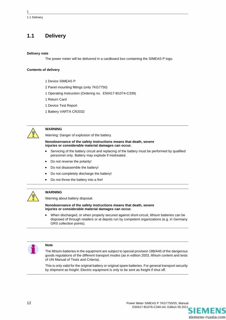
Delivery noteThe power meter will be delivered in a cardboard box containing the SIMEAS P logo.
Contents of delivery
1 Device SIMEAS P
2 Panel mounting fittings (only 7KG7750)
1 Operating Instruction (Ordering no. E50417-B1074-C339)
1 Return Card
1 Device Test Report
1 Battery VARTA CR2032
WARNING
Warning: Danger of explosion of the battery.
Nonobservance of the safety instructions means that death, severeinjuries or considerable material damages can occur.• Servicing of the battery circuit and replacing of the battery must be performed by qualified
personnel only. Battery may explode if mistreated.
• Do not reverse the polarity!
• Do not disassemble the battery!
• Do not completely discharge the battery!
• Do not throw the battery into a fire!
WARNING
Warning about battery disposal.
Nonobservance of the safety instructions means that death, severeinjuries or considerable material damages can occur.
• When discharged, or when properly secured against short-circuit, lithium batteries can be disposed of through retailers or at depots run by competent organizations (e.g. in Germany GRS collection points).
Note
The lithium-batteries in the equipment are subject to special provision 188/A45 of the dangerous goods regulations of the different transport modes (as in edition 2003, lithium content and tests of UN Manual of Tests and Criteria).
This is only valid for the original battery or original spare batteries. For general transport security by shipment as freight: Electric equipment is only to be sent as freight if shut off.
12 Power Meter SIMEAS P 7KG7750/55, ManualE50417-B1076-C340-A4, Edition 05.2011

1
1.2 Ordering Data
1.2 Ordering Data
1.2.1 SIMEAS P 7KG7750
DescriptionPower Meter
SIMEAS P 7KG7750Built in device for control panels 96 mm x 96 mm with graphic display
I/O module (optional)A
2 binary outputs B2 binary inputs C2 analog outputs DC 0 mA to 20 mA / DC 4 mA to 20 mA D2 analog inputs DC 0 mA to 20 mA E3 relay outputs G
Front protection classIP 41 1IP 65 3
Communication interface and protocolsPROFIBUS DP and Modbus RTU/ASCII / RS485 0IEC 60870-5-103 and Modbus RTU/ASCII / RS485 1
Without (standard)
Order No.
7KG 7 7 5 0 A A- A0 - 0 0
13Power Meter SIMEAS P 7KG7750/55, ManualE50417-B1076-C340-A4, Edition 05.2011

1
1.2 Ordering Data
1.2.2 SIMEAS P 7KG7755
1.2.3 Parameterization Package
DescriptionPower Meter
SIMEAS P 7KG7755Snap on mounting unit 96 mm x 96 mm, without grafic display, front protection class IP 20
I/O Module (optional)
2 binary outputs B2 binary inputs C2 analog outputs DC 0 mA to 20 mA / DC 4 mA to 20 mA D2 analog inputs DC 0 mA to 20 mA E3 relay outputs G
Communication interface and protocolsPROFIBUS DP and Modbus RTU/ASCII / RS485 0IEC 60870-5-103 and Modbus RTU/ASCII / RS485 1
Without (standard)
Order No.
77KG 7 5 5 - 0
A
- 0 A A0 A 0
Description
SIMEAS P Parameterization Package
TypeRS485 / 5 V-power supply unit / supply voltage AC 230 V / 50 Hz
B
5 0 - ASoftware SIMEAS P PAR, RS232/RS485 adapter
RS485 / 5 V-power supply unit /supply voltage AC 120 V / 60 Hz
A
Order No.
07KG 7 8
14 Power Meter SIMEAS P 7KG7750/55, ManualE50417-B1076-C340-A4, Edition 05.2011

1
1.3 Dimensions
1.3 Dimensions
1.3.1 Device Variant SIMEAS P 7KG7750
Fig. 1-1 SIMEAS P 7KG7750, variant IP 41
Note: All dimensions in mm
15Power Meter SIMEAS P 7KG7750/55, ManualE50417-B1076-C340-A4, Edition 05.2011

1
1.3 Dimensions
Fig. 1-2 SIMEAS P 7KG7750, variant IP 65
Note: All dimensions in mm
16 Power Meter SIMEAS P 7KG7750/55, ManualE50417-B1076-C340-A4, Edition 05.2011

1
1.3 Dimensions
Fig. 1-3 SIMEAS P 7KG7750
Technical Data for HousingHousing: Flush mounting according to IEC 61554/DIN 43700
Panel section: 92.0+0,8 mm x 92.0+0,8 mm
Protection class: front IP 41 or IP 65
terminals IP 20
for personal security IP 1x
TerminalsTerminals for power supply, voltage inputs, current inputs, binary outputs, I/O modules (optional):
Conductor cross section, rigid max.: 2.5 mm2
Conductor cross section with ferrule: 1.5 mm2
Stripping length: 9 mm
Tightening torque: 0.4 Nm to 0.5 Nm
RS485 interface 9-pole D-Sub miniature female connector
Note: All dimensions in mm
17Power Meter SIMEAS P 7KG7750/55, ManualE50417-B1076-C340-A4, Edition 05.2011

1
1.3 Dimensions
1.3.2 Device Variant SIMEAS P 7KG7755
Fig. 1-4 SIMEAS P 7KG7755, snap on mounting unit
Technical Data for HousingHousing snap on mounting unit
Protection class front / terminals IP 20
for personal security IP 1x
TerminalsTerminals for power supply, voltage inputs, current inputs, binary outputs, I/O modules (optional):
Conductor cross section, rigid max.: 2.5 mm2
Conductor cross section with ferrule: 1.5 mm2
Stripping length: 9 mm
Tightening torque: 0.4 Nm to 0.5 Nm
RS485 interface 9-pole D-Sub miniature female connector
Note: All dimensions in mm
18 Power Meter SIMEAS P 7KG7750/55, ManualE50417-B1076-C340-A4, Edition 05.2011

1
1.4 Block Diagram
1.4 Block Diagram
Fig. 1-5 Block diagram SIMEAS P 7KG7750/55
SIM
EAS
P 7K
G77
5x
Term
inal
blo
ck F
L1L2
L3N
L1
kl
L2L3
Mea
sure
men
tA
uxilia
ry V
olta
ge
N/-
L/+
Bina
ry O
utpu
ts
com
mun
icat
ion
J
RS
485,
Mod
bus
and
IEC
608
70-5
-103
1 P
rote
ctiv
e G
roun
d3
A4
RTS
5 G
ND
6 +5
V8
BPR
OFI
BU
S D
P1
Pro
tect
ive
Gro
und
3 B
4 C
TRL-
A5
GN
D6
+5 V
8 A
RS4
85
RS2
32
Volta
geC
urre
nt
k
k
l
lL3
N
DC
: 24
to 2
50 V
AC: 1
00 to
230
V
Term
inal
blo
ck E
Term
inal
blo
ck H
B2
B1
R
Term
inal
blo
ck G
L1
L2
PG
Note
The integrated battery serves to buffer the memory and the real-time clock.
19Power Meter SIMEAS P 7KG7750/55, ManualE50417-B1076-C340-A4, Edition 05.2011

1
1.4 Block Diagram
Fig. 1-6 I/O modules (option)
Additional input and output modules (see ordering data, chapter 1.2) are available for the device 7KG7750/55:
• Binary inputs (2 contacts with common contact)
• Binary outputs (2 contacts with common contact)
• Relay outputs (3 contacts with common contact)
• Analog inputs (2 channels)
• Analog outputs (2 channels)
A1
Binary outputs
1 2
Relay outputs
2 31 RR
slot A optional slot A optional
Binary inputs
21 R R
DCDC
slot A optional
slot A optional
Analogue outputs
slot A optional
Analogue inputs
1 250 Ohm 50 Ohm
+ 1 2
2 x 0 to 20 mA
A2 A3 A4 A1 A2 A3
A4A1 A2 A3
A4
A1 A2 A3 A4
+- - + - +
A1 A2 A3 A4
SIMEAS P7KG775x
I/O Modules2 x 0 to 20 mA/4 to 20 mA
20 Power Meter SIMEAS P 7KG7750/55, ManualE50417-B1076-C340-A4, Edition 05.2011

1
1.5 Interface and Terminals
1.5 Interface and Terminals
1.5.1 Terminal Assignment SIMEAS P 7KG7750/55
Fig. 1-7 Terminal assignment SIMEAS P 7KG7750/55
WARNING
Warning about missing protection.
Nonobservance of the safety instructions means that death, severeinjuries or considerable material damages can occur.
• Always connect the earth to the earthing terminal of the SIMEAS P 7KG7750/55.
21Power Meter SIMEAS P 7KG7750/55, ManualE50417-B1076-C340-A4, Edition 05.2011

1
1.5 Interface and Terminals
1.5.2 Terminal Assignment
Table 1-1 Terminal assignment
Terminal Function
E1 IL1 IA Phase current 1, input
E2 IL1 IA Phase current 1, output
E3 IL2 IB Phase current 2, input
E4 IL2 IB Phase current 2, output
E5 IL3 IC Phase current 3, input
E6 IL3 IC Phase current 3, output
F1 UL1 UA Phase voltage 1
F2 UL2 UB Phase voltage 2
F3 UL3 UC Phase voltage 3
F4 UN UN Star point voltage measurement
G1 Common contact
Common contact
Common contact for the internal binary outputs 1 and 2
G2 B2 B2 Binary output 2
G3 B1 B1 Binary output 1
H1 Protective ground
H2 N/- N/- Supply voltage -
H3 L/+ L/+ Supply voltage +
A1 to A4 Optional, see Table 1-2, I/O modules
22 Power Meter SIMEAS P 7KG7750/55, ManualE50417-B1076-C340-A4, Edition 05.2011

1
1.5 Interface and Terminals
Table 1-2 I/O modules (see Figure 1-6)
Modul Type Terminal Allocation Ordering no.
(see chapter 1.2)
not equipped A
BO
2 binary outputs n.c.BO2+BO1+BOR
B
BI
2 binary inputs BI2+BIRBIRBI1+
C
AO
2 analog outputs AO2-AO2+AO1-AO1+
D
AI
2 analog inputs AI2-AI2+AI1-AI1+
E
RO
3 relay outputs RORRO3RO2RO1
G
23Power Meter SIMEAS P 7KG7750/55, ManualE50417-B1076-C340-A4, Edition 05.2011
1
1.5 Interface and Terminals
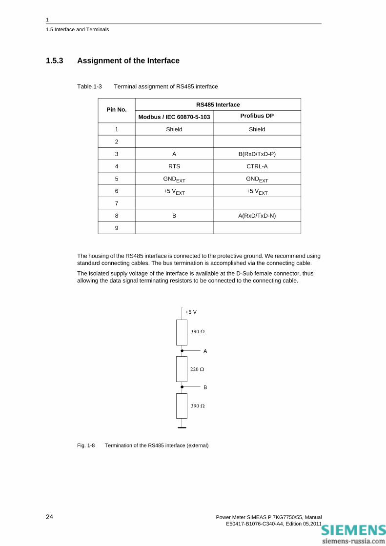
1.5.3 Assignment of the Interface
Table 1-3 Terminal assignment of RS485 interface
The housing of the RS485 interface is connected to the protective ground. We recommend using standard connecting cables. The bus termination is accomplished via the connecting cable.
The isolated supply voltage of the interface is available at the D-Sub female connector, thus allowing the data signal terminating resistors to be connected to the connecting cable.
Fig. 1-8 Termination of the RS485 interface (external)
Pin No.RS485 Interface
Modbus / IEC 60870-5-103 Profibus DP
1 Shield Shield
2
3 A B(RxD/TxD-P)
4 RTS CTRL-A
5 GNDEXT GNDEXT
6 +5 VEXT +5 VEXT
7
8 B A(RxD/TxD-N)
9
+5 V
390 Ω
220 Ω
390 Ω
B
A
24 Power Meter SIMEAS P 7KG7750/55, ManualE50417-B1076-C340-A4, Edition 05.2011

1
1.5 Interface and Terminals
1.5.4 Connection Examples
1.5.4.1 General
The following are examples of current and voltage input connections (according to DIN 43807). The device can be connected without current or voltage transformers as long as the maximum voltage and current ratings of the device are not exceeded.
The voltage transformers can be connected in wye or open-delta configurations.
All input and/or output terminals not required for a particular input voltage and current configura-tion are not used.
Terminal designation of measuring instruments for single-phase and three-phase alternating current according to DIN 43807 / Oct. 1983:
1.5.4.2 Single-phase
DIN 43807 1 3 4 6 7 9 11 2 5 8
SIMEAS P E1 E2 E3 E4 E5 E6 F4 F1 F2 F3
Note
The single ground connection of the instrument transformers is shown for illustration only. Actual grounds must be installed directly at each instrument transformer.
25Power Meter SIMEAS P 7KG7750/55, ManualE50417-B1076-C340-A4, Edition 05.2011

1
1.5 Interface and Terminals
1.5.4.3 Three-phase, Three-wire, Balanced
1.5.4.4 Three-phase, Three-wire, Unbalanced ( 2 I, Aron Circuit)
NOTICEDo not exceed the maximum permissible voltage.Nonobservance of the safety instructions means that property damage can result.• The maximum secondary voltage is AC 480 V in this example. Do not exceed the maximum
permissible voltage between phase and earth.
NOTICEDo not exceed the maximum permissible voltage.Nonobservance of the safety instructions means that property damage can result.• The maximum secondary voltage is AC 480 V in this example. Do not exceed the maximum
permissible voltage between phase and earth.
26 Power Meter SIMEAS P 7KG7750/55, ManualE50417-B1076-C340-A4, Edition 05.2011

1
1.5 Interface and Terminals
1.5.4.5 Three-phase, Four-wire, Balanced
1.5.4.6 Three-phase, Four-wire, Unbalanced (Low-voltage System)
1.5.4.7 Three-phase, Four-wire, Unbalanced (High-voltage System)
27Power Meter SIMEAS P 7KG7750/55, ManualE50417-B1076-C340-A4, Edition 05.2011

1
1.5 Interface and Terminals
1.5.5 Commissioning
The ratings and information on the nameplate should be checked prior to connecting the power supply voltage. In particular, power supply voltage ratings, as well as input voltage and current ratings should be verified. An operating period of 15 minutes is required before the device will perform within specified accuracy limits.
The battery serves to buffer the memory and the real-time clock of the SIMEAS P. The battery is included in the delivery scope. The battery is delivered in an isolated state. Remove the cover of the battery slot on the top of the device and remove the battery and the isolation. Insert the battery without isolation according to the polarity printed on the top of the device (marking shield) and replace the battery cover.
If the battery voltage is low the battery symbol occurs in status line of the display. Please change the battery in this case as described before. Use an isolated tool to remove the battery from the device to avoid a short circuit!
1.5.6 Electrical Connection
WARNING
Warning about battery change.
Nonobservance of the safety instructions means that death, severeinjuries or considerable material damages can occur.
• All electrical connections must get separated from the device before the battery change.
WARNING
Warning about dangerous voltages when operating an electrical device.
Nonobservance of the safety instructions means that death, severeinjuries or considerable material damages can occur.
• Only qualified people shall work on and around this device. They must be thoroughly familiar with all warnings and safety notices in this instruction manual as well as with the applicable safety steps, safety regulations, and precautionary measures.
• The following work is partly carried out at existence endangering voltages.
28 Power Meter SIMEAS P 7KG7750/55, ManualE50417-B1076-C340-A4, Edition 05.2011

1
1.5 Interface and Terminals
Note
During electrical installation, all rules and regulations for power systems must be observed.
• Short-circuit the current transformer secondary circuits before current connections to the device are opened.
• The protective ground terminal of the device must be connected to the protective ground of the panel or cubicle.
• For connection of an auxiliary DC voltage, the correct polarity must be used.
• All of the terminals should be checked to verify proper connections.
• The polarities and phasing of all instrument transformers should be checked.
• Before initially energizing the device with supply voltage, it shall be situated in the operating area for at least two hours to ensure temperature equalization and to avoid humidity and con-densation problems.
29Power Meter SIMEAS P 7KG7750/55, ManualE50417-B1076-C340-A4, Edition 05.2011

1
1.5 Interface and Terminals
30 Power Meter SIMEAS P 7KG7750/55, ManualE50417-B1076-C340-A4, Edition 05.2011

Operation 2 Contents
The following chapters describe the operation of the SIMEAS P 7KG7750. The operation of the SIMEAS P 7KG7755 is not described because this device has no display.
2.1 Screen Display 32
2.2 Screen Content 32
31Power Meter SIMEAS P 7KG7750/55, ManualE50417-B1076-C340-A4, Edition 05.2011

2
2.1 Screen Display
2.1 Screen Display
Once the SIMEAS P has been connected and configured for its measuring task, the measured quantities you have defined are displayed in screens.
• Specific screens can be selected via the two front arrow buttons .
• Press an arrow button once to display the next or previous screen.
• Hold an arrow button down to scroll through the screens automatically
• If desired, automatic scrolling can be programmed for normal display. When scrolling, the screens are arranged in a loop format (i.e., the first screen follows the last in one direction, whereas the last screen follows the first in the opposite direction, etc.).
2.2 Screen Content
The simple and individual screen design enables you to read the information relevant to your measuring tasks at a glance. The number of screens (max. 20), the screen types and their con-tents can be parameterized as required.
2.2.1 Screen Types
The following screen types are available:
• three measured values - digital
• six measured values - digital
• U, I, cos φ
• three min-max values
UL1 231.35 V
UL2 230.87 V
UL3 229.46 V
2/10AP<> Bd/Prm Min-Max 12:30 230.11
UL1 233.53 V 228.59
UL2 231.47 V 227.33
UL3 233.48 V
2/10AP<> Bd/Prm
UL1 231.35 V
UL2 230.87 V
UL3 229.46 V
2/10AP<> Bd/Prm
32 Power Meter SIMEAS P 7KG7750/55, ManualE50417-B1076-C340-A4, Edition 05.2011

2
2.2 Screen Content
2.2.1.1 3 Measured Values - Digital
Display of any three measured quantities from the measured quantities Table 3-1.
2.2.1.2 6 Measured Values - Digital
Display of any six measured quantities from the measured quantities Table 3-1.
2.2.1.3 U, I and cos φ (Phasors)
• fast overview of the network conditions
• digital display of all connected phases
• measured quantities: U, I, cos φ
UL1 231.35 V
UL2 230.87 V
UL3 229.46 V
2/10AP<> Bd/Prm
UL1 10.12 kV UL2 10.34 kV UL3 10.42 kVIL1 245.4 A IL2 244.6 A IL3 249.4 A
2/10AP<> Bd/Prm
U I 10.12 kV 245.4 A 10.34 kV 244.6 A 10.42 kV 249.4 A cos φ 0.922 ind 0.923 ind 0.927 ind
33Power Meter SIMEAS P 7KG7750/55, ManualE50417-B1076-C340-A4, Edition 05.2011

2
2.2 Screen Content
2.2.1.4 3 Min-Max Values
• Up to three measured quantities from the measured quantities tables (except energy and metered values) can be monitored here.
• The minimum, average and maximum values since recording was last initiated are displayed for a specific measured quantity. The values remain valid in case of a power failure.
• Recording is initiated (date and time):
• when the device is switched on or
• via "Reset" of the Min-Max values at the programming level.
• If no date/time is set, the duration of the recording is indicated in hours and minutes. If the time is set, the date and time of recording initiation are indicated.
29.08 Min-Max 12:30 230.11
UL1 233.53 V 228.59
UL2 231.47 V 227.33
UL3 233.48 V
2/10AP<> Bd/Prm
34 Power Meter SIMEAS P 7KG7750/55, ManualE50417-B1076-C340-A4, Edition 05.2011

2
2.2 Screen Content
2.2.2 Status Bar
The screens (except for U, I, cos φ) have a status line that displays the status of the device.
Meaning of the symbols
<> Bd/Prm 2/10AP
Diagnosis of bus and device Binary outputs Status of device
password protection
Phase rotation indicator
Receive or deliverenergy Battery symbol Screen number and total
number of screens
Symbol Meaning
< > Serial telegram sent / receive
Bd Searching for the Profibus baud rate
Cfg Waiting for the correct configuration of Profibus
Prm Waiting for the correct parameters of Profibus
Direction of rotation from UL1 to UL2 (UA to UB)
Receive (this symbol) or delifer (resistor symbol) energy
Status of binary outputs
If the battery voltage falls below the defined threshold, then the symbol will be displayed in the status line. Please replace the battery in this case (see chapter 1.5.5).
If the password protection is active a lock with a closed fastener will be displayed.
A Recording of average values active
P Recording of power values active
35Power Meter SIMEAS P 7KG7750/55, ManualE50417-B1076-C340-A4, Edition 05.2011

2
2.2 Screen Content
36 Power Meter SIMEAS P 7KG7750/55, ManualE50417-B1076-C340-A4, Edition 05.2011
Measured Quantities 3 Contents
The following chapters describe the measured quantities.
3.1 Measured Quantities - Depend on the Connection Type 38
3.2 Formulas and Calculation of Derived Quantities 42
3.3 Connection Modes 47
3.4 View of Measured Quantities and Error Limits 49
37Power Meter SIMEAS P 7KG7750/55, ManualE50417-B1076-C340-A4, Edition 05.2011

3
3.1 Measured Quantities - Depend on the Connection Type
3.1 Measured Quantities - Depend on the Connection Type
Table 3-1 Measured quantities that depend on the input connection type
No. Measured Quantity Designation
1 (Space line)* X X X X X X
2 Voltage L1-N X X X U L13 Voltage L2-N X U L24 Voltage L3-N X U L35 Voltage L1-L2 X X X X U L126 Voltage L2-L3 X X X X U L237 Voltage L3-L1 X X X X U L318 Voltage E-N* 0 0 0 0 0 U E-N9 Current L1 X X X X X X I L110 Current L2 X X X I L211 Current L3 X X X I L312 Average current* X X ΣI / 3 I13 Neutral current N X X I014 Real power L1 X X P L115 Real power L2 X P L216 Real power L3 X P L317 Real power Σ X X X X X P18 Reactive power L1 X X Q L119 Reactive power L2 X Q L220 Reactive power L3 X Q L321 Reactive power Σ X X X X X Q22 Apparent power L1 X X S L123 Apparent power L2 X S L224 Apparent power L3 X S L325 Apparent power Σ X X X X X S26 Active factor cos φ L1 X X COS PHI L127 Active factor cos φ L2 X COS PHI L228 Active factor cos φ L3 X COS PHI L329 Active factor cos φ Σ X X X X X COS PHI30 Power factor L1 X X PF L131 Power factor L2 X PF L232 Power factor L3 X PF L333 Power factor Σ X X X X X PF* see Table 3-2, Explanation
1-ph
ase
AC
Cur
rent
Thre
e-w
ireTh
ree-
phas
eB
alan
ced
Thre
e-w
ireTh
ree-
phas
eU
nbal
ance
d (3
I)
Thre
e-w
ireTh
ree-
phas
eU
nbal
ance
d (2
I)
Four
-wire
Thre
e-ph
ase
Bal
ance
d
Four
-wire
Thre
e-ph
ase
Unb
alan
ced
38 Power Meter SIMEAS P 7KG7750/55, ManualE50417-B1076-C340-A4, Edition 05.2011

3
3.1 Measured Quantities - Depend on the Connection Type
34 Phase angle L1 X X PHI L135 Phase angle L2 X PHI L236 Phase angle L3 X PHI L337 Phase angle Σ X X X X X PHI38 System frequency X X X X X X f39 Asymmetrical voltage X ASYM U40 Asymmetrical current X ASYM I41 THD voltage L1 X X THDU L142 THD voltage L2 X THDU L243 THD voltage L3 X THDU L344 THD current L1 X X THDI L145 THD current L2 X THDI L246 THD current L3 X THDI L347 Harmonic voltage L1* X X X X X X HU L1
5, 7, 11, 13, 17, 1948 Harmonic voltage L2* X X X HU L2
5, 7, 11, 13, 17, 1949 Harmonic voltage L3* X X X HU L3
5, 7, 11, 13, 17, 1950 Harmonic current L1* X X X X X X HI L1
5, 7, 11, 13, 17, 1951 Harmonic current L2* X X X HI L2
5, 7, 11, 13, 17, 1952 Harmonic current L3* X X X HI L3
5, 7, 11, 13, 17, 1953 Active energy L1 demand* X X WpL1d54 Active energy L2 demand* X WpL2d55 Active energy L3 demand* X WpL3d56 Active energy Σ demand* X X X X X WpΣd57 Active energy L1 supply* X X WpL1s58 Active energy L2 supply* X WpL2s59 Active energy L3 supply* X WpL3s60 Active energy Σ supply* X X X X X WpΣs61 Active energy L1 total* X X WpL1t62 Active energy L2 total* X WpL2t63 Active energy L3 total* X WpL3t64 Active energy Σ total* X WpΣt65 Active energy (3L) demand
net*X X X X X Wpnet
* see Table 3-2, Explanation
No. Measured Quantity Designation
1-ph
ase
AC
Cur
rent
Thre
e-w
ireTh
ree-
phas
eB
alan
ced
Thre
e-w
ireTh
ree-
phas
eU
nbal
ance
d (3
I)
Thre
e-w
ireTh
ree-
phas
eU
nbal
ance
d (2
I)
Four
-wire
Thre
e-ph
ase
Bal
ance
d
Four
-wire
Thre
e-ph
ase
Unb
alan
ced
39Power Meter SIMEAS P 7KG7750/55, ManualE50417-B1076-C340-A4, Edition 05.2011

3
3.1 Measured Quantities - Depend on the Connection Type
66 Reactive energy L1 inductive
X X WqL1i
67 Reactive energy L2 inductive
X WqL2i
68 Reactive energy L3 inductive
X WqL3i
69 Reactive energy Σinductive
X X X X X WqΣi
70 Reactive energy L1 capacitve
X X WqL1c
71 Reactive energy L2 capacitve
X WqL2c
72 Reactive energy L3 capacitve
X WqL3c
73 Reactive energy Σ capacitve
X X X X X WqΣc
74 Reactive energy total L1* X X WqL1t75 Reactive energy total L2* X WqL2t76 Reactive energy total L3* X WqL3t77 Reactive energy total Σ* X X X X X WqΣt78 Apparent energy L1 X X WL179 Apparent energy L2 X WL280 Apparent energy L3 X WL381 Apparent energy Σ X X X X X WΣ
82 Counter 1 / 2 / 3 / 4* X X X X X X Cntr. 1, 2, 3, 483 Binary inputs X* X* X* X* X* X*84 Analog inputs X* X* X* X* X* X** see Table 3-2, Explanation
No. Measured Quantity Designation
1-ph
ase
AC
Cur
rent
Thre
e-w
ireTh
ree-
phas
eB
alan
ced
Thre
e-w
ireTh
ree-
phas
eU
nbal
ance
d (3
I)
Thre
e-w
ireTh
ree-
phas
eU
nbal
ance
d (2
I)
Four
-wire
Thre
e-ph
ase
Bal
ance
d
Four
-wire
Thre
e-ph
ase
Unb
alan
ced
40 Power Meter SIMEAS P 7KG7750/55, ManualE50417-B1076-C340-A4, Edition 05.2011

3
3.1 Measured Quantities - Depend on the Connection Type
Explanations to the Table 3-1
Table 3-2 Explanation
No. Name Description
1 (Space line) If a space line is selected as a measured quantity, the corresponding fields remain empty on the display screens.
8 Voltage E-N The displayed value of the voltages (E-N) is always 0, but the value of residual voltage is shown, if it occurs.
12 Average current The average value of the three phase currents is displayed here.
47 to 52
Harmonics U / I For harmonics up to the 21st, the standards (IEC 61000-2-2 and EN 50160) specify compatibility levels only for harmonics of orders 5, 7, 11, 13, 17, and 19. Those of even order and those divisible by 3 are considered irrelevant. Therefore, on the "Harmonics" screen, selection is limited to all uneven orders up to the 21st. The selection of single harmonics on the measured values screens is limited to the 5th, 7th, 11th, 13th, 17th and 19th.For voltage harmonics, values are displayed as a percentage of the first harmonic. For current harmonics, the values are displayed directly in A.
53 to 60
Active energy demand The default setting (industry mode) is "Load (standard)" indicated by a positive energy flow direction. You can configure the power supply company mode. In this mode, a positive value indicates "Generator".
61 to 64
Active energy total The sum of the absolute values (without sign) of active energy demand and active energy supply.
65 Active energy (3L)net demand
Net energy is equal to energy demand minus energy supply. Because this measured value can be negative and can decrease as well as increase, it is not possible to use this measured value to generate pulses via the output contacts.
74 to 77
Reactive energy total The sum of the absolute values (without sign) of inductive and capacitive kvarh.
82 Counter 1 / 2 / 3 / 4 Number of limit violations
83 84
Binary inputs,analog inputs
optional
41Power Meter SIMEAS P 7KG7750/55, ManualE50417-B1076-C340-A4, Edition 05.2011

3
3.2 Formulas and Calculation of Derived Quantities
3.2 Formulas and Calculation of Derived Quantities
3.2.1 Calculation of Derived Quantities
Line Derived Quantity Formula Note
1 RMS value voltage, distorted waveform included ∑
=
=64
1
2
641
ννuV
2 RMS value voltage, fundamental component U1 only 2
22
1baV +
= From the Fourier coefficients a and b of the fundamental component
3 RMS value current, distorted waveform included ∑
=
=64
1
2
641
ννiI
4 RMS value voltage, fundamental component I1 only 2
22
1baI +
= From the Fourier coefficients a and b of the fundamental component
5 Active power PStd ∑
=
=64
1641
ννν ivP
From sample values
6 Active power PFour 1111 IbVbIaVaP += From the Fourier coefficients
of the fundamental component 7 Active power PDIN
)(21
1nn
nnn IbVbIaVaP += ∑
=
From the Fourier coefficients of the fundamental component and from the harmonics.
8 Reactive power QStd
∑=
−⋅=
64
1
21
641
ν
π
νν
jeivQ
Standard up to now, additional fault for distortions1
9 Reactive power QFour 1111 IaVbIbVaQ +=
10 Reactive power QDIN )(
21
1nn
nnntot IaVbIbVaQ += ∑
=
From the Fourier coefficients of the fundamental component
11 Apparent power SStd 332211 IVIVIVS NNN ⋅+⋅+⋅= From the RMS values
according to line 1 and 3 12 Apparent power SFour 2
322
21
23
22
21 IIIVVVS NNN ++⋅++= From the RMS values
according to line 1 and 3 13 Apparent power SDIN 2
322
21
23
22
21 IIIVVVS NNN ++⋅++= From the RMS values
according to line 2 and 4 14 Power factor
SP
=ϕcos or DINSP1
No sign!
15 Power factor DIN
DINSP
=ϕcos No sign!
16 Power factor cos ϕ
1
1cosSP
=ϕ Four quadrants according to note 4
17 Phase Angle
1
1arctanPQ
=ϕ From the fundamental component only!
1 According to classic measuring devices (electrodynamic power meter)
42 Power Meter SIMEAS P 7KG7750/55, ManualE50417-B1076-C340-A4, Edition 05.2011

3
3.2 Formulas and Calculation of Derived Quantities
Line Derived Quantity Formula Note
18 System frequency
PTN
f =
Refer to note 1
19 Active energy demand 0
1
>= ∑=
PforPWν
ν The active energy demand will be calculated every second.
20 Active energy supply 0
1
<= ∑=
PforPWν
ν The active energy supply will be calculated every second.
21 Active energy without sign
∑=
=1ν
νPW Calculation without sign
22 Active energy net demand
∑=
=1ν
νPW Calculation with sign
23 Asymmetrical voltage U or current I
MGV =
Refer to note 2 Range is 0 to ∞, avoid division by 0!
24 THD voltage, current 1
1
−=MMTHD tot
Refer to note 3
25 Harmonics From Fourier transformation
43Power Meter SIMEAS P 7KG7750/55, ManualE50417-B1076-C340-A4, Edition 05.2011

3
3.2 Formulas and Calculation of Derived Quantities
3.2.2 Remarks to the Measuring Quantities
Note 1N: Nominal value of the counting pulses per period at nominal value of the system frequency
T: Nominal value of the period length of the system frequency in µs
P: Counted pulses within one period
V: Asymmetry
G: Unbalanced system
M: Balanced system
Mn: Vector of the measured quantity, ULN or IL, from Fourier transformation
Note 2
No. of Equation Equation
1
2
3
4
5
6
22 BAG +=
⎟⎠⎞
⎜⎝⎛ ++⎟
⎠⎞
⎜⎝⎛ −+= πϕπϕ
32cos
32cos 1331221 MMMA
⎟⎠⎞
⎜⎝⎛ ++⎟
⎠⎞
⎜⎝⎛ −= πϕπϕ
32sin
32sin 133122 MMB
22 DCM +=
⎟⎠⎞
⎜⎝⎛ −+⎟
⎠⎞
⎜⎝⎛ ++= πϕπϕ
32cos
32cos 1331221 MMMC
⎟⎠⎞
⎜⎝⎛ −+⎟
⎠⎞
⎜⎝⎛ += πϕπϕ
32sin
32sin 1331222 MMD
44 Power Meter SIMEAS P 7KG7750/55, ManualE50417-B1076-C340-A4, Edition 05.2011

3
3.2 Formulas and Calculation of Derived Quantities
Note 3Derivation of the formula:
Total distortion D according to IEC 61000-2-2:
Equation No. 7:
un: Un/U1
n Order of the harmonic
Un Voltage of the n-th harmonic
U1 Voltage of the fundamental component
N 40, for SIMEAS P: 21
Mn Harmonic (n-th order) of voltage or current
M1 Fundamental component of voltage or current
It is possible to derive the result from the harmonic M1 and the RMS value Mges of the distorted measured quantity. With the root „H“ from equation 8:
Equation No. 8:
Mges: RMS value of the distorted measured quantity U or I
M1: RMS value of the fundamental component of the measured quantity
Inserting the values into the equation results in:Equation 9:
Inserting 1/M1 into the root results in:Equation 10:
∑∑
==
==N
nn
N
nn M
MuD
2
2
12
2 1
21
2 MMH ges −=
21
2
11
11 MMM
HM
THD ges −==
12
1
2
21
21
2
−=−
=MM
MMM
THD gesges
45Power Meter SIMEAS P 7KG7750/55, ManualE50417-B1076-C340-A4, Edition 05.2011

3
3.2 Formulas and Calculation of Derived Quantities
Note 44 Quadrants
90°III
III IV
Q+ Q+
Q- Q-
SQ
P
φ
270°P-, active energy - P+, active energy +
cos φ = negative + cap
cos φ = positive + capcos φ = negative + ind
cos φ = positive + ind
0°180°
PF+
PF+
PF+
PF+
46 Power Meter SIMEAS P 7KG7750/55, ManualE50417-B1076-C340-A4, Edition 05.2011
3
3.3 Connection Modes
3.3 Connection Modes
3.3.1 Four-wire Three-phase Current with Any Load
Depending on the measuring method some quantities to be measured are not available. For the method according to DIN, for example the apparent power S or S1 are available; only SDIN can be calculated.
3.3.2 Single-phase AC
The measuring path for the voltage is A-N for the voltage and A for the other quantities. This applies also for the power values. The apparent power according to DIN, the reactive power Qtot DIN and the asymmetry are not valid.
3.3.3 Four-wire Three-phase Current with Symmetrical Load
Current A and voltage A-N are available. You can display the same measured quantities as for Single-phase AC. For power Σ, the value calculated from U and I must be multiplied by 3. For power, power factor, cos φ, phase angle and energy only the sum is relevant. The measurement values Asymmetrical U or I are not available. THD and harmonics can be derived for A only.
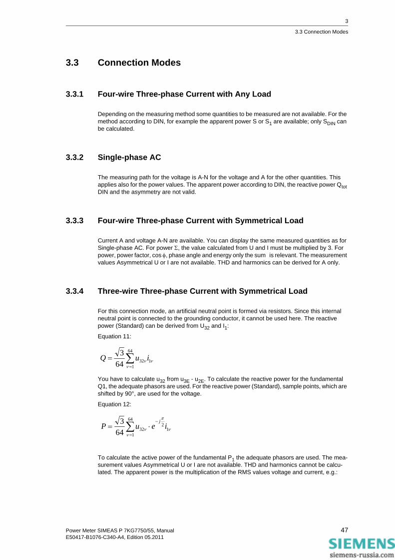
3.3.4 Three-wire Three-phase Current with Symmetrical Load
For this connection mode, an artificial neutral point is formed via resistors. Since this internal neutral point is connected to the grounding conductor, it cannot be used here. The reactive power (Standard) can be derived from U32 and I1:
Equation 11:
You have to calculate u32 from u3E - u2E. To calculate the reactive power for the fundamental Q1, the adequate phasors are used. For the reactive power (Standard), sample points, which are shifted by 90°, are used for the voltage.
Equation 12:
To calculate the active power of the fundamental P1 the adequate phasors are used. The mea-surement values Asymmetrical U or I are not available. THD and harmonics cannot be calcu-lated. The apparent power is the multiplication of the RMS values voltage and current, e.g.:
∑=
=64
113264
3ν
νν iuQ
∑=
−⋅=
64
11
23264
3ν
ν
π
ν ieuPj
47Power Meter SIMEAS P 7KG7750/55, ManualE50417-B1076-C340-A4, Edition 05.2011

3
3.3 Connection Modes
Equation 13:
For S1, the RMS values of the fundamental component are used; as symmetrical load is sup-posed SDIN = S.
3.3.5 Three-wire Three-phase Current with Any Load
For this connection mode, the phase-to-ground voltages are not available. Active and reactive powers are calculated from the formulas of the two-wattmeter (Aron) circuit:
Equation 14:
This is also valid for the calculation via Fourier analysis. For the reactive power according to clas-sic measuring devices (electro dynamic power meter), the following equation is valid:
Equation 15:
Distortions will cause an additional fault. For the apparent power (classical method), the following equation is valid::
Equation 16:
For the apparent power according to DIN calculated from the phase voltages, the following equa-tion is valid:
Equation 17:
In both cases, current B must be calculated from the geometrical sum of the currents -A and -C. To do this, you can sum up the sample points or the Fourier coefficient.
The artificial neutral point does not allow measuring the voltage asymmetry exactly and is not realized. The measured values are only exact, if you use a four-wire net with neutral point. Often the three-wire net is used only to save the cable connection to current transformer 2. Only in this case, it would be useful to measure the asymmetry.
1323 IUS ⋅⋅=
∑∑==
+=64
1323
64
1112 64
1641
ννν
ννν iuiuP
∑∑=
−−
=
+=64
1
21
32321
1
64
112 64
1641
ν
π
νν
π
νν
ν
jjeiueiuQ
( )3231123 IUIUS +=
( ) 23
22
21
231
223
2123
1 IIIUUUS ++⋅++=
48 Power Meter SIMEAS P 7KG7750/55, ManualE50417-B1076-C340-A4, Edition 05.2011

3
3.4 View of Measured Quantities and Error Limits
3.4 View of Measured Quantities and Error Limits
Table 3-3 Measured values and tolerances
Measured Values Measuring Path 1 Menu Tolerances 2
Voltage L1-N, L2-N, L3-N ±0.2 %
Voltage L1-L2, L2-L3, L3-L1, Σ 3 ±0.2 %
Current L1, L2, L3, N, Σ 3 ±0.2 % Active power P + demand, - supply L1, L2, L3, Σ ±0.5 % Reactive power Q + cap, - ind L1, L2, L3, Σ ±0.5 %
Apparent power S L1, L2, L3, Σ ±0.5 %
Power factor |cosϕ| 4 L1, L2, L3, Σ ±0.5 %
Active power factor cosϕ 4 L1, L2, L3, Σ ±0.5 %
Phase angle 4 L1, L2, L3, Σ ±2°
System frequency 5 L1-N ±10 mHz
Active energy demand L1, L2, L3, Σ ±0.5 %
Active energy supply L1, L2, L3, Σ ±0.5 %
Active energy total L1, L2, L3, Σ ±0.5 %
Active energy net demand Σ ±0.5 %
Reactive energy cap L1, L2, L3, Σ ±0.5 %
Reactive energy ind L1, L2, L3, Σ ±0.5 %
Reactive energy total L1, L2, L3, Σ ±0.5 %
Apparent energy L1, L2, L3, Σ ±0.5 %
Unbalance voltage Four-wire system ±0.5 %
Unbalance current Four-wire system ±0.5 %
THD voltage L1, L2, L3 ±0.5 %
THD current L1, L2, L3 ±0.5 % Harmonic voltage 5., 7., 11., 13., 17. and 19. H. L1, L2, L3 ±0.5 %
Harmonic current 5., 7., 11., 13., 17. and 19. H. L1, L2, L3 ±0.5 %
Limit violation Counter 1 to 4
Analog input 6 external ±0.5 %
Binary input 6 external
49Power Meter SIMEAS P 7KG7750/55, ManualE50417-B1076-C340-A4, Edition 05.2011
3
3.4 View of Measured Quantities and Error Limits
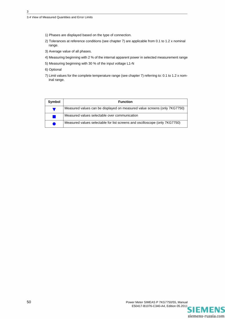
1) Phases are displayed based on the type of connection.
2) Tolerances at reference conditions (see chapter 7) are applicable from 0.1 to 1.2 x nominal range.
3) Average value of all phases.
4) Measuring beginning with 2 % of the internal apparent power in selected measurement range
5) Measuring beginning with 30 % of the input voltage L1-N
6) Optional
7) Limit values for the complete temperature range (see chapter 7) referring to: 0.1 to 1.2 x nom-inal range.
Symbol Function
Measured values can be displayed on measured value screens (only 7KG7750)
Measured values selectable over communication
Measured values selectable for list screens and oscilloscope (only 7KG7750)
50 Power Meter SIMEAS P 7KG7750/55, ManualE50417-B1076-C340-A4, Edition 05.2011

Device Parameterization 4 Contents
The following chapters describe the device parameterization of the SIMEAS P 7KG7750 using a graphic display. The parameterization of the SIMEAS P 7KG7755 using PC software is explained in chapter 5.
4.1 Operating Notes 52
4.2 Overview of the Levels 54
4.3 Main Menu 55
4.4 Basic Settings 58
4.5 About SIMEAS 72
4.6 Reset 72
4.7 Reset Memory 73
4.8 Parameterization Screens 73
4.9 I/O Modules 75
4.10 Memory Management 75
4.11 Data Logger 76
4.12 Overflow of Measured Values 78
51Power Meter SIMEAS P 7KG7750/55, ManualE50417-B1076-C340-A4, Edition 05.2011
4
4.1 Operating Notes
4.1 Operating Notes
This chapter describes all of the setting options of the SIMEAS P that are made via the front but-tons.
The Main Menu (programming level 2, see chapter 4.3) can be accessed :
• from the measured values screens, the min-max values screens or the screen U, I, cos φ via the ENTER button,
• from the data logger: use the arrow buttons to select the Date/Time screen and press the ENTER button.
4.1.1 Button Functions
The following functions are performed via the buttons:
• Moving the cursor to the entry line,
• Scrolling through selection lists when entering settings,
• Selecting numbers when entering numerical values.
If the buttons are held down, the scrolling continues automatically. The buttons generally cycle between cursor, parameters or numbers.
The selected line, setting, or number is confirmed by pressing the ENTER button.
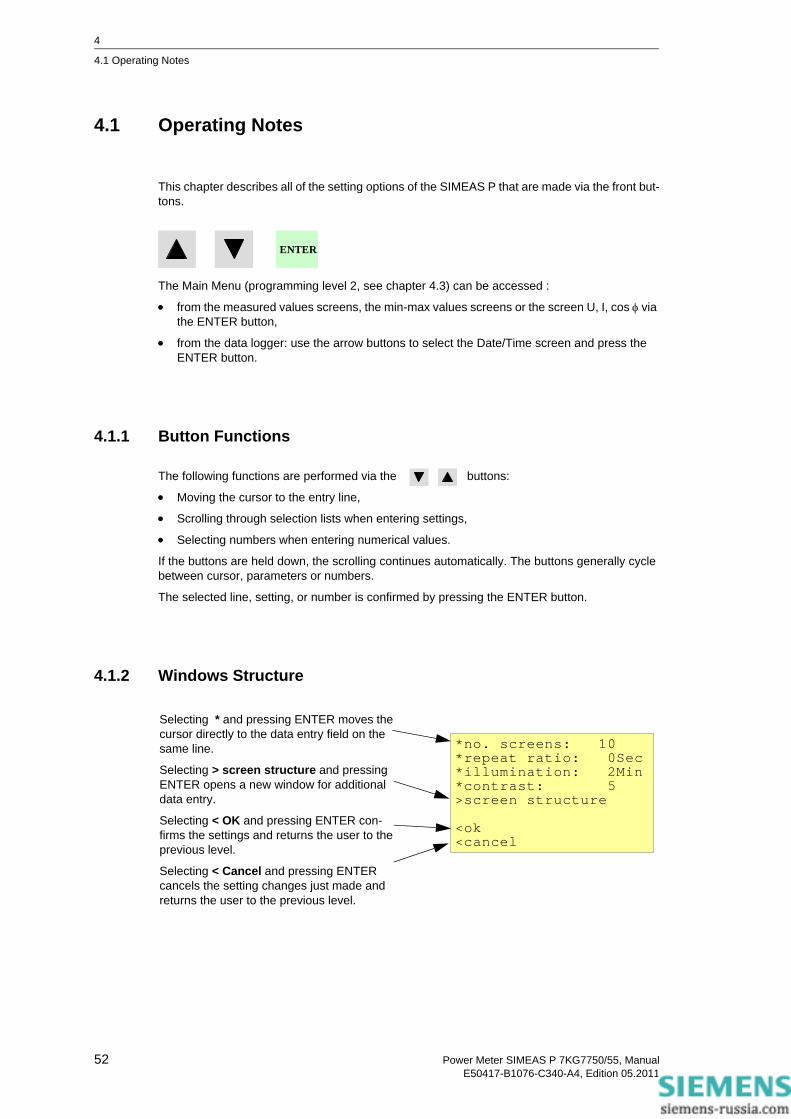
4.1.2 Windows Structure
ENTER
*no. screens: 10*repeat ratio: 0Sec*illumination: 2Min*contrast: 5>screen structure
<ok<cancel
Selecting * and pressing ENTER moves the cursor directly to the data entry field on the same line.
Selecting > screen structure and pressing ENTER opens a new window for additional data entry.
Selecting < OK and pressing ENTER con-firms the settings and returns the user to the previous level.
Selecting < Cancel and pressing ENTER cancels the setting changes just made and returns the user to the previous level.
52 Power Meter SIMEAS P 7KG7750/55, ManualE50417-B1076-C340-A4, Edition 05.2011

4
4.1 Operating Notes
4.1.3 Notes on Parameterization
• The measured quantities offered for selection in the screens depend on the connection type selected.
• The numbers entered are checked for plausibility and the note: "ERR" is displayed if required. The input value is then set to the maximum value.
• If the power supply voltage is switched off during programming, the message illustrated below appears when the device is restarted. Therefore, the power supply voltage should only be switched off in level 1 (measuring screens).
Select No via the buttons to retain the settings as they existed prior to the loss of power supply voltage.
Choose Yes by pressing the ENTER button to restore the default settings.
Attention!
Parameter incorrectreset?
No Yes(arrow) (Enter)
Note
This means, that you should always leave the parameter screens completely (OK or Cancel) until the measurement screens are displayed again. This ensures that all parameters will be accepted by the device.
Note
Please check the parameters and the adjustment data afterwards, to ensure the correct function of the SIMEAS P.
If you have adjusted the device manually (refer to chapter 6), the adjustment data will not be overwritten by default settings.
53Power Meter SIMEAS P 7KG7750/55, ManualE50417-B1076-C340-A4, Edition 05.2011

4
4.2 Overview of the Levels
4.2 Overview of the Levels
Main menu
1. Level 2. Level 3. Level 4. Level 5. Level
Screens Data logger Date / Time
Basic screens Limit valuegroup
Binary states
Currenttransformer
Settingsoverview
Basicsettings
Settings
Voltagetransformer
Inputconnection
about SIMEASLanguage
Limit valuesOutputsResetDate / Time
EnergypulseInterfaceReset
memoryLog
Changingcode
Calibration
Additionalsettings
Furthersettings
Screenstructure
Screencontent
I/O module
Memory
2.1
2.2
2.3
2.4
2.5
3.1
3.2
3.3
3.4
3.5
3.6
3.7
3.8
3.9
4.1
4.2
4.3
4.4
4.5
4.6
4.7
4.8
4.9
4.10
4.11
5.1
5.2
5.3
5.4
5.6
IEC 60870-5-103 settings
5.5
54 Power Meter SIMEAS P 7KG7750/55, ManualE50417-B1076-C340-A4, Edition 05.2011

4
4.3 Main Menu
4.3 Main Menu
The main menu is used to access various submenus.
4.3.1 Screens
Use the ENTER key to switch between the displays
• Main menu
• Measured value screens
• Data logger
4.3.2 Settings
The setup masks for device parameterization can be selected from the Parameters menu.
>screens >settings >language >date/ time >log
<close
>basic settings >about SIMEAS >reset >reset memory >screen content >I/O module >memory <close
55Power Meter SIMEAS P 7KG7750/55, ManualE50417-B1076-C340-A4, Edition 05.2011

4
4.3 Main Menu
4.3.3 Language
LanguageHere you can select the language of the SIMEAS P.
• D = German
• GB = English
Designation
Change of the conductor designations in the screens:
• a, b, c
• L1, L2, L3
4.3.4 Date / Time
SIMEAS P requires time information for the following functions:
• Oscilloscope
• Log entries
• Measured value memory
One binary input (optional) may be used for time synchronization via minute impulse.
The data for summer/winter time and the binary input can only be set via the PC software SIM-EAS P parameterization (refer to chapter 5).
*language: GB *description:a,b,c
<ok <cancel
*date: 01.02.2001 *time: 10:17:57 am *12/24h: 12 CEST: 00.00 to 00.00binary input:BE2 <ok <cancel
56 Power Meter SIMEAS P 7KG7750/55, ManualE50417-B1076-C340-A4, Edition 05.2011

4
4.3 Main Menu
4.3.5 Log
The screen Log displays date and time of the most recent status changes.
failure dd.mm.yy hh:mm:ss
power on . . : :
settings . . : :
reset limit . . : :
reset average . . : :
reset power . . : :
reset osc. . . : :
set clock . . : :
reset binary . . : :
57Power Meter SIMEAS P 7KG7750/55, ManualE50417-B1076-C340-A4, Edition 05.2011

4
4.4 Basic Settings
4.4 Basic Settings
Here you can make the most important settings directly on the device.
4.4.1 Settings Overview
Settings Overview is where the most important settings associated with the device are displayed.
>settings overview>input connections>output contacts>interface>change code>calibration>additional settings<ok
calc. mode:standard 4 wire unbalancedcurrent range: 1.2Avoltage range: 480Vrel 1: limit value1rel 2: limit value2bus adr.:111<cancel
58 Power Meter SIMEAS P 7KG7750/55, ManualE50417-B1076-C340-A4, Edition 05.2011
4
4.4 Basic Settings
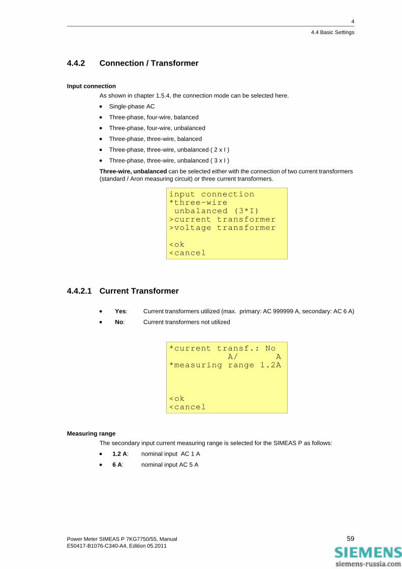
4.4.2 Connection / Transformer
Input connectionAs shown in chapter 1.5.4, the connection mode can be selected here.
• Single-phase AC
• Three-phase, four-wire, balanced
• Three-phase, four-wire, unbalanced
• Three-phase, three-wire, balanced
• Three-phase, three-wire, unbalanced ( 2 x I )
• Three-phase, three-wire, unbalanced ( 3 x I )
Three-wire, unbalanced can be selected either with the connection of two current transformers (standard / Aron measuring circuit) or three current transformers.
4.4.2.1 Current Transformer
• Yes: Current transformers utilized (max. primary: AC 999999 A, secondary: AC 6 A)
• No: Current transformers not utilized
Measuring rangeThe secondary input current measuring range is selected for the SIMEAS P as follows:
• 1.2 A: nominal input AC 1 A
• 6 A: nominal input AC 5 A
input connection*three-wire unbalanced (3*I)>current transformer>voltage transformer
<ok<cancel
*current transf.: No A/ A*measuring range 1.2A
<ok<cancel
59Power Meter SIMEAS P 7KG7750/55, ManualE50417-B1076-C340-A4, Edition 05.2011

4
4.4 Basic Settings
Caution• You must make these settings for a direct connection or for a connection with current trans-
formers.
• The selected measuring range must be greater than the secondary rating of the current transformer!
• The accuracy of SIMEAS P (see table 3-3) is based on the selected measuring range.
• The determination of this range indicates the maximum current value that can be displayed on the device.
ExampleCT rating: 500 / 1 A
Measuring range 1.2 A: Maximum display range: AC 0 A to 600 A
Measuring range 6 A: Maximum display range: AC 0 A to 3000 A
4.4.2.2 Voltage Transformer
• Yes: Voltage transformers are utilized (max. primary: AC 1000 kV, secondary: AC 600 V)
• No: Voltage transformers are not utilized
Measuring range• 132 V nominal input AC 100/110 V
• 228 V nominal input AC 190 V
• 480 V nominal input AC 400 V
• 828 V nominal input AC 690 V
Note
When you change the current transformer settings, the power calculation in the device has to be reset.
*voltage transf.:No kV/ V*meas. range L-L 480V
<ok<cancel
60 Power Meter SIMEAS P 7KG7750/55, ManualE50417-B1076-C340-A4, Edition 05.2011

4
4.4 Basic Settings
Up to ULN = 480 V, the SIMEAS P can be connected directly without a transformer. In three- and four-phase networks, except for three-phase networks without neutral (see the respective notes), the SIMEAS P can also be connected directly without a transformer up to ULL = 690 V.
Caution• You must make these settings for a direct connection or for a connection with current trans-
formers.
• The selected measuring range must be greater than the secondary rating of the voltage transformer!
• The accuracy of SIMEAS P is based on the selected measuring range.
• The determination of this range indicates the maximum voltage value that can be displayed on the device.
• "The frequency measurement of the SIMEAS P is initiated only when the measured voltage is > 30 % of the maximum voltage of the measuring range.
• Measurements in three-phase networks without neutral in V-connection (1:1 transformer) are possible up to a nominal voltage of ULL = 400 V. With this nominal voltage, the measuring range ULL = 690 V must be parameterized.
• For measurements in three-phase networks without neutral in V-connection and a nominal voltage of ULL = 690 V, the voltage must be transformed to ULL ≤ 400 V. The measuring range to be parameterized is then also ULL = 690 V.
• In IT networks, the SIMEAS P cannot be connected directly because the voltage is measured against the PE conductor connection and the input impedance of the device causes a leak-age current against earth. The leakage current can cause tripping of the leakage protective system in IT networks. Please make sure that the maximum permissible input voltage of the SIMEAS P against earth UL-PE = 480 V is not exceeded (e.g., due to an earth fault of one phase). Voltage transformers must be used in IT networks.
Selectable measuring range L-L Equivalent to measuring range L-N
AC 0 V to 132 V AC 0 V to 76.2 V
AC 0 V to 228 V AC 0 V to 132 V
AC 0 V to 480 V AC 0 V to 276 V
AC 0 V to 828 V AC 0 V to 480 V
61Power Meter SIMEAS P 7KG7750/55, ManualE50417-B1076-C340-A4, Edition 05.2011

4
4.4 Basic Settings
4.4.3 Outputs
Here, the user can determine the function of the programmable output contacts (potential-free electronic relays). Further contacts can be assigned in devices with I/O modules of the binary output or relay output type (option).
Selection• Off Contact has no function
• SIMEAS P is on Contact closed if power supply voltage is present.
• Energy pulses If selected, a new window "Energy Pulses" appears.
• Limit value 1 If selected, a new window "Limit Value 1" appears.
• Limit value 2 If selected, a new window "Limit Value 2" appears.
• Limit value 3 If selected, a new window "Limit Value 3" appears.
• Limit value 4 If selected, a new window "Limit Value 4" appears.
• Limit value 5 If selected, a new window "Limit Value 5" appears.
• Limit value 6 If selected, a new window "Limit Value 6" appears.
• Limit value 7 If selected, a new window "Limit Value 7" appears.
• Direction of rotation This option allows you to output the rotation direction of the voltage.
• 1: Contact activated; direction of rotation for clockwise display(phase sequence L1-L2-L3, clockwise rotation)
• 0: Contact deactivated; direction of rotation for anti-clockwise display(2 phases interchanged, anti-clockwise rotation)
*relay1: limit value1 *relay2: rotation
<ok<cancel
62 Power Meter SIMEAS P 7KG7750/55, ManualE50417-B1076-C340-A4, Edition 05.2011
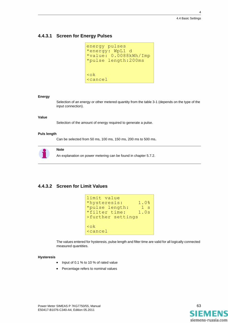
4
4.4 Basic Settings
4.4.3.1 Screen for Energy Pulses
EnergySelection of an energy or other metered quantity from the table 3-1 (depends on the type of the input connection).
ValueSelection of the amount of energy required to generate a pulse.
Puls lengthCan be selected from 50 ms, 100 ms, 150 ms, 200 ms to 500 ms.
4.4.3.2 Screen for Limit Values
The values entered for hysteresis, pulse length and filter time are valid for all logically connected measured quantities.
Hysteresis• Input of 0.1 % to 10 % of rated value
• Percentage refers to nominal values
energy pulses*energy: WpL1 d*value: 0.0088kWh/Imp *pulse length:200ms
<ok<cancel
Note
An explanation on power metering can be found in chapter 5.7.2.
limit value*hysteresis: 1.0%*pulse length: 1 s*filter time: 1.0s>further settings
<ok<cancel
63Power Meter SIMEAS P 7KG7750/55, ManualE50417-B1076-C340-A4, Edition 05.2011

4
4.4 Basic Settings
Puls length• 0.5 s, 1 s, 5 s, 10 s, 30 s, 60 s, 300 s
• (triggering for as long as a limit violation applies)
Filter timeInput of 0.0 s to 9.9 s max. (minimum time during which a limit violation must occur to launch a triggering)
Limit values• Selection of any measured quantity from the table 3-1 (no energy or metered quantities)
• Selection as to whether triggering should be launched when the measured quantity exceeds or drops below the threshold value (< >).
• Selection of the threshold value that initiates triggering.
• Additional measured quantities can be connected logically via "AND" or „OR". A maximum of six measured quantities are possible.
Note
Limit violations are recorded reliably only from a duration of > 1 s.
Note
You can parameterize limit value groups also in „Additional Settings“ - „Counter“ (level 4, see chapter 4.2)!
64 Power Meter SIMEAS P 7KG7750/55, ManualE50417-B1076-C340-A4, Edition 05.2011

4
4.4 Basic Settings
4.4.4 Communication Interface
4.4.4.1 General Settings
Bus addresInput address 1 to 254
Baud rate • Selection only for connection to a PC or Modbus. The following baud rates are allowed:
300 bit/s, 600 bit/s, 1200 bit/s, 2400 bit/s, 4800 bit/s, 9600 bit/s, 19200 bit/s, 38400 bit/s, 57600 bit/s, 115200 bit/s.
• The baud rate of the Profibus is supported automatically up to 12 Mbit/s with the selection being performed via the master station.
Parity• Only for Modbus (N = None, E = Even, O = Odd)
Protocol• SIMEAS P ASCII Protocol: PC RS485 (for connection to a PC via programming software)
• Profibus DP (with firmware version V3 only) orIEC 60870-5-103 (with firmware version V4 only)
• Modbus RTU
• Modbus ASCII
*bus address:112*baudrate: 19200Bd*parity: E*protocol: IEC 103>IEC 103 settings
<ok<cancel
Note
The Baud rate is selected during parameterization (using SIMEAS P Par or the display). It can be set in the range between 300 bit/s and 115200 bit/s, for the IEC 60870-5-103 protocol, how-ever, only in the range between 9600 bit/s and 38400 bit/s.
Note
At delivery, the following communication parameters are preset:Address: 1Protocol: PC-RS485Baud rate: 9600 bit/sParity: No
65Power Meter SIMEAS P 7KG7750/55, ManualE50417-B1076-C340-A4, Edition 05.2011
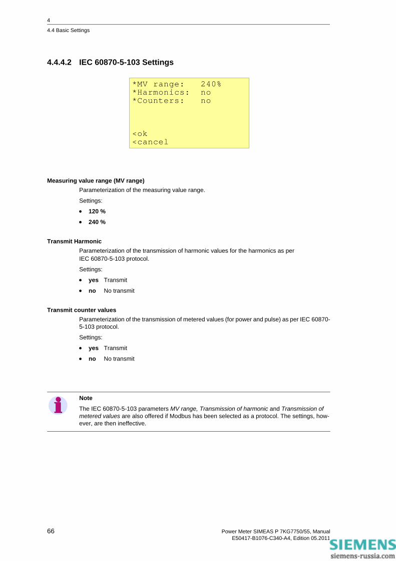
4
4.4 Basic Settings
4.4.4.2 IEC 60870-5-103 Settings
Measuring value range (MV range)Parameterization of the measuring value range.
Settings:
• 120 %
• 240 %
Transmit HarmonicParameterization of the transmission of harmonic values for the harmonics as perIEC 60870-5-103 protocol.
Settings:
• yes Transmit
• no No transmit
Transmit counter valuesParameterization of the transmission of metered values (for power and pulse) as per IEC 60870-5-103 protocol.
Settings:
• yes Transmit
• no No transmit
*MV range: 240%*Harmonics: no*Counters: no
<ok<cancel
Note
The IEC 60870-5-103 parameters MV range, Transmission of harmonic and Transmission of metered values are also offered if Modbus has been selected as a protocol. The settings, how-ever, are then ineffective.
66 Power Meter SIMEAS P 7KG7750/55, ManualE50417-B1076-C340-A4, Edition 05.2011
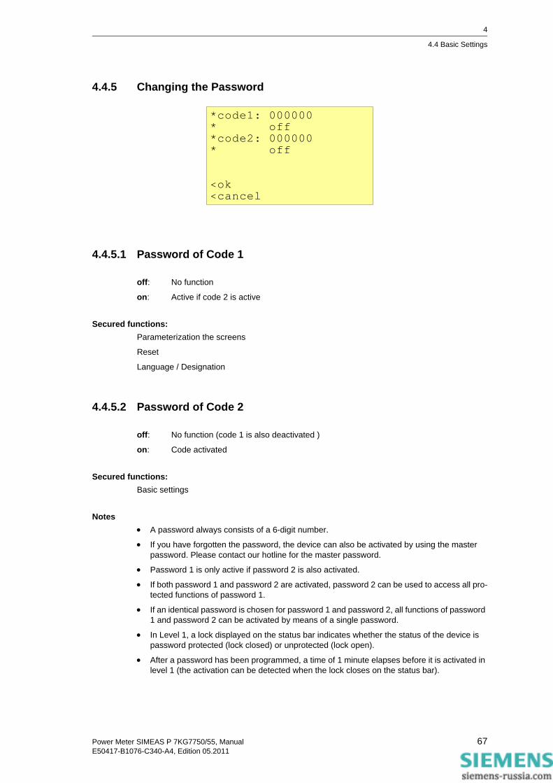
4
4.4 Basic Settings
4.4.5 Changing the Password
4.4.5.1 Password of Code 1
off: No function
on: Active if code 2 is active
Secured functions:Parameterization the screens
Reset
Language / Designation
4.4.5.2 Password of Code 2
off: No function (code 1 is also deactivated )
on: Code activated
Secured functions:Basic settings
Notes• A password always consists of a 6-digit number.
• If you have forgotten the password, the device can also be activated by using the master password. Please contact our hotline for the master password.
• Password 1 is only active if password 2 is also activated.
• If both password 1 and password 2 are activated, password 2 can be used to access all pro-tected functions of password 1.
• If an identical password is chosen for password 1 and password 2, all functions of password 1 and password 2 can be activated by means of a single password.
• In Level 1, a lock displayed on the status bar indicates whether the status of the device is password protected (lock closed) or unprotected (lock open).
• After a password has been programmed, a time of 1 minute elapses before it is activated in level 1 (the activation can be detected when the lock closes on the status bar).
*code1: 000000* off*code2: 000000* off
<ok<cancel
67Power Meter SIMEAS P 7KG7750/55, ManualE50417-B1076-C340-A4, Edition 05.2011

4
4.4 Basic Settings
• If the protected functions are called in the menu, a window for entering the password appears.
• If a protected setting is activated by means of a password, all other settings associated with this password are activated as well. A reactivation is required after a time of 1 minute has elapsed in level 1.
4.4.6 Calibration
See chapter 6 "Calibration".
4.4.7 Additional Settings
Counter 1 to 4Counters 1 to 4 can be displayed in the screens. Limit value groups can be assigned to these counters. If a counter is selected, another window is opened for defining the limit value group (see outputs).
>counter1-limitvalue1>counter2-limitvalue2>counter3-limitvalue3>counter4-limitvalue4>further settings
<ok <cancel
Note
Limit value groups can also be parameterized under Outputs - Limit value group (level 4, see chapter 4.2)!
68 Power Meter SIMEAS P 7KG7750/55, ManualE50417-B1076-C340-A4, Edition 05.2011

4
4.4 Basic Settings
4.4.8 Further Settings
Calculation mode• Standard
• DIN
• Fourier
The calculation mode for some measured quantities can be changed here. For further informa-tion, see the chapter 3.1.
Current direction• + Default setting for correct connection according to standard and back panel marking
• - Current direction is negated (change the current direction to avoid changing the connec-tors)
Direction of power• + positive energy flow direction = energy demand
negative energy flow direction = energy supply
• - positive energy flow direction = energy supply
negative energy flow direction = energy demand
Zero pointThe zero point suppression can be changed here.
Can be selected from 0.0 % to 10.0 % of the upper limit of the measurement range (default set-ting: 1 %)
*calc. mode: standard*current direction: +*direction of power:+*zero point: 0.3000%Uen: calculationAO settings<ok<cancel
Note
Due to its high precision, SIMEAS P can measure voltages and currents even without measuring values connected to the device. If you do not want this behaviour in your application, you can suppress measuring below a certain threshold.
69Power Meter SIMEAS P 7KG7750/55, ManualE50417-B1076-C340-A4, Edition 05.2011

4
4.4 Basic Settings
Uen• Measurement (default setting)
• Calculation
Uen will be calculated if terminal N is grounded (standard application).
Uen has to be measured if L2 or L3 is grounded (special application).
Figure 4-1 Network connection with grounded phase L2
Analog output setting (only visible in screen for devices with optional analog output module)If the device is equipped with an optional analog output module (see table 1-2, order code D), analog outputs are configured in following screen:
These settings allow writing the transduced measured values (range 0 mA to 20 mA) to analog outputs of analog output module via Modbus master or IE 60870-5-103 master.
Start value• holding
After power interruption the analog output is set to last in register saved value.
• default
After power interruption the analog output is set to current value in register.
L1
L2
K L
k l
L3
K
k l k l
K
L
L
UU U
X XX
u uu
x xx
Analog output setting*start value:holding*range from: -32767* to: 32767*current range:0-20mA
<ok<cancel
70 Power Meter SIMEAS P 7KG7750/55, ManualE50417-B1076-C340-A4, Edition 05.2011

4
4.4 Basic Settings
Range for Modbus protocol• from: min. -32767
• to: max. 32767
Calculation:
Example:
from: 0
to: 1000
selected range: 4-20 mA
transmitted AO value: 500
Current range• 0-20 mA
• 4-20 mA
AOfern from–
AOreal AOmin–----------------------------------------- to from–
range max min–( )--------------------------------------=
500 0–AOreal 4–--------------------------- 1000 0–
20 4–--------------------- 12mA==
71Power Meter SIMEAS P 7KG7750/55, ManualE50417-B1076-C340-A4, Edition 05.2011
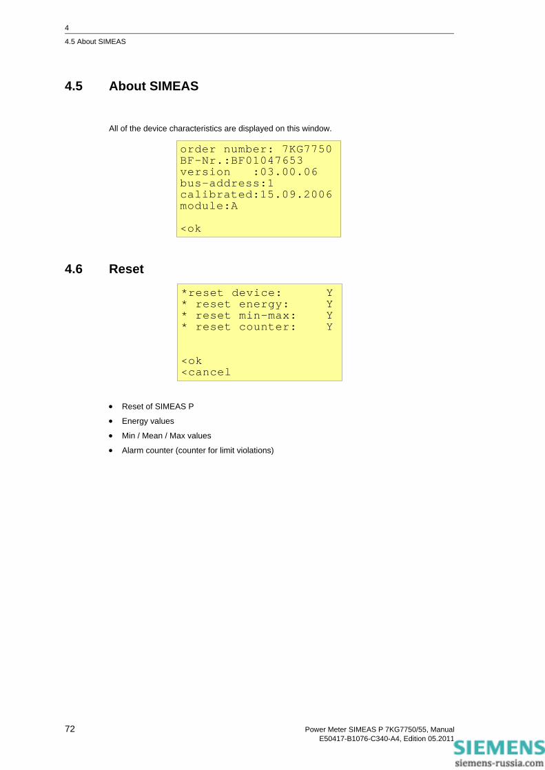
4
4.5 About SIMEAS
4.5 About SIMEAS
All of the device characteristics are displayed on this window.
4.6 Reset
• Reset of SIMEAS P
• Energy values
• Min / Mean / Max values
• Alarm counter (counter for limit violations)
order number: 7KG7750BF-Nr.:BF01047653version :03.00.06bus-address:1calibrated:15.09.2006module:A
<ok
*reset device: Y* reset energy: Y* reset min-max: Y* reset counter: Y
<ok<cancel
72 Power Meter SIMEAS P 7KG7750/55, ManualE50417-B1076-C340-A4, Edition 05.2011

4
4.7 Reset Memory
4.7 Reset Memory
The following records are deleted in the memory and restarted in the event of a reset:
• Power values
• Mean values
• Alarm log: states of the limit value groups
• Binary log: states of the binary states
• Oscilloscope
4.8 Parameterization Screens
The contents and display mode of the various screens are established in this window.
Number of Screens1 to 20: The number of screens that can be selected in level 2 via the buttons .
Screen interval (repeat ratio)0 s to 60 s
0 s: fixed screens (only selection via buttons possible)
1 s to 60 s: scrolls automatically to the next screen after 1 s to 60 s
*reset power values:Y*reset mean values: N*reset alarm log: Y*reset binary log: N*reset oscilloscope:N
<ok<cancel
*no. screens: 4*repeat ratio: 0Sec*illumination: 99Min*contrast: 4>screen structure
<ok<cancel
73Power Meter SIMEAS P 7KG7750/55, ManualE50417-B1076-C340-A4, Edition 05.2011

4
4.8 Parameterization Screens
Illumination0 min to 99 min
0 min = Illumination off
99 min = Illumination on permanently
Contrast0 to 9 (default setting: 4)
Screen structure
The contents of specific measuring screens are programmed on the "Screen Structure" window.
ScreenSelection of a specific screen among the number previously established. The contents of the screen are automatically displayed when switching from one screen to the next.
ContentsThe contents of the selected screen can be established or modified here as follows:
• 3 measured values digital
• 6 measured values digital
• 3 Min - Max values
• Voltages, currents, cos φ, phases L1, L2, L3
If specific screen content is selected, the input fields for the corresponding characteristics are automatically displayed.
*screen no.: 10*type: min-max*1:Ua*2:Ub*3:Uc
<ok<cancel
74 Power Meter SIMEAS P 7KG7750/55, ManualE50417-B1076-C340-A4, Edition 05.2011

4
4.9 I/O Modules
4.9 I/O Modules
This screen displays the optional I/O modules together with their current state. For devices with-out I/O modules the table remains empty.
4.10 Memory Management
You can partition the main memory of 1 MByte as required for the recording of mean values, outputs, limit violations, binary state changes and oscilloscope records.
The total of the percentages entered must reach but not exceed 100%.
Notes• For power recording, the recording time will be calculated from the number of channels to be
recorded and the period time.
• For mean values and power recording settings, you have to use the PC software SIMEAS P Parameterization (ordering number see chapter 1.2).
module stateE analog- E = 0.0 mA input E = 0.0 mA
>ok
memory management*average values:20%*power values: 20%*oscilloscope: 20%*limit values: 20%*binary log: 20%<ok<cancel
75Power Meter SIMEAS P 7KG7750/55, ManualE50417-B1076-C340-A4, Edition 05.2011

4
4.11 Data Logger
4.11 Data Logger
The group Data logger displays the following screens:
• Date and time
• Limit value group
• Binary states
To work with the group Data logger proceed as follows:
• In the Main menu, select Screens and press two times ENTER.
• Use the buttons to access the group Data logger.
• To leave the Data logger, go back to the screen Date and Time and press ENTER to return to the Main menu.
4.11.1 Data Logger Date and Time
This screen shows the current time of the SIMEAS P (to set the values refer chapter 4.3.4).
4.11.2 Data Logger Limit Violation Group
This screen displays all limit violations ordered by time. You have to read the lines from bottom to top.
Status line
09.03.2005
15 : 34 : 12
limit time reason 1 10.03.05 08:19:15ULN1 10.03.05 210.2V 08:52:261 10.03.05 08:53:15
2/10AP<> Bd/Prm
76 Power Meter SIMEAS P 7KG7750/55, ManualE50417-B1076-C340-A4, Edition 05.2011

4
4.11 Data Logger
Notes• Press ENTER to activate the arrow buttons up/down to display all messages.
• Press ENTER again to deactivate this mode. This allows you to switch to the other screens via the arrow buttons up/down.
• Go back to the screen Date and Time and press ENTER to return to the Main menu.
4.11.3 Data Logger Binary States
This screen displays all changes of the binary states ordered by time. You have to read the lines from bottom to top.
Notes• Press ENTER to activate the arrow buttons up/down to display all messages.
• Press ENTER again to deactivate this mode. This allows you to switch to the other screens via the arrow buttons up/down.
• Go back to the screen Date and Time and press ENTER to return to the Main menu.
status linebinary time stateIn A-1 20.01.08 on 10:20:10Out1 20.01.08 on 10:20:10Out1 20.01.08 off 10:21:10
77Power Meter SIMEAS P 7KG7750/55, ManualE50417-B1076-C340-A4, Edition 05.2011

4
4.12 Overflow of Measured Values
4.12 Overflow of Measured Values
If the measured values determined in a measurement circuit are higher than the possible values of the parameterized measuring range, a value overflow will be displayed. In addition, this value overflow is signaled via Modbus or IEC 60870-5-103 protocol.
The overflow is displayed or transmitted if the nominal AC voltage or AC current values are exceeded by 20 %.
Presentation of the measured value overflow in the display
An overflow of the measured values AC voltage and AC current, as well as the derived quantities such as active power, reactive power, harmonic, power, THD and cos φ is displayed by ***. The energy counting is only stopped, not reset.
Transmission of the measured value overflow using the Modbus protocolA special Modbus register (register address 40200) has been reserved for the transmission of the measured value overflow. For detailed information, please see the Powermeter SIMEAS P - Modbus manual (order no. E50417-B1076-C241).
Transmission of the measured value overflow using the IEC 60870-5-103 protocolThe measured value overflow is transmitted using the IEC 60870-5-103 protocol. For detailed information, see the Power Meter SIMEAS P 7KG7750/55 - Communication Protocol IEC 60870-5-103 manual (order no. E50417-B1000-C375).
UL1-N 10.12 kV UL2-N 10.34 kV UL3-N 10.42 kVIL1 245.4 A IL2 244.6 A IL3 249.4 A
2/10AP<> Bd/Prm
UL1-N *** IL1-N *** PL1-N *** QL1-N *** HUL1-7 ***HIL1-7 ***
78 Power Meter SIMEAS P 7KG7750/55, ManualE50417-B1076-C340-A4, Edition 05.2011
Parameterization via PC Software 5 Content
The parameterization using a PC is described in the following chapters.
5.1 Basics 80
5.2 Overview of Parameterization 81
5.3 Date / Time Settings and Transmit 82
5.4 Dialog Window SIMEAS P 83
5.5 Basic Settings 84
5.6 Screens Setting on SIMEAS P 7KG7750 86
5.7 Input / Output Modules 89
5.8 Additionals 98
5.9 Memory Management 104
5.10 Updating the Firmware 116
5.11 Resetting Values in the Device 118
5.12 Reading the Device Memory 119
5.13 Changing the Communication Parameters 123
79Power Meter SIMEAS P 7KG7750/55, ManualE50417-B1076-C340-A4, Edition 05.2011

5
5.1 Basics
5.1 Basics
In order to program your SIMEAS P via the PC software SIMEAS P Parameterization you have to prepare for operation or parameterization:
Preconditions• The device is ready to operate.
• The PC software SIMEAS P Parameterization (ordering number see chapter 1.2) is installed on your PC.
• The parameterization cable set (ordering number see chapter 1.2) or a RS485 converter is available.
Parameterization1. Connect the device and the PC as described in the online help.
2. Set the connection parameters on the device:
• Select the protocol "PC-RS485".
• Select the baud rate for the connection.
3. Set the connection parameters in the PC software SIMEAS P Parameterization (Connection → Setup connection). Make sure to use the same baud rate.
4. Load the settings from the device (Device → Connection configuration → Receive).
5. Edit the settings in the PC software.
6. Send the new settings to the device again (Device → Connection configuration → Send).
Note
SIMEAS P Parameterization displays the parameters depending on the ordering number of the device.
Reading the ID from the device recognizes the device type and sets the functional scope.
Note
All others functions of SIMEAS P Parameterization are described in the online help (key F1).
80 Power Meter SIMEAS P 7KG7750/55, ManualE50417-B1076-C340-A4, Edition 05.2011

5
5.2 Overview of Parameterization
5.2 Overview of Parameterization
The following figures give an overview on all layers of the PC software SIMEAS P Parameteriza-tion depending on the device type.
5.2.1 Overview of Parameterization 7KG7750
5.2.2 Overview of Parameterization 7KG7755
81Power Meter SIMEAS P 7KG7750/55, ManualE50417-B1076-C340-A4, Edition 05.2011

5
5.3 Date / Time Settings and Transmit
5.3 Date / Time Settings and Transmit
You can set the date and time of the internal clock of the SIMEAS P using the SIMEAS P Param-eterization PC software. You can either accept the current PC time or define and transmit a freely selectable system time. To do this, proceed as follows:
To set the internal clock and transmit the time to a connected device, you have two options for calling up the Send date and time dialog window:
Select the menu item Device → Setup device clock, or
click the clock symbol in the toolbar.
The Send date and time dialog window is displayed.
Send PC time1. Click the Send PC time button to send the current PC time.
2. If the PC time has been transmitted correctly and accepted by the connected device, a con-firmation will be displayed.
3. Click the Close button.
Send manual time setting1. Change the entries in the fields Day to Min using your keyboard.
2. Then click Send time manually.
3. If the PC time has been transmitted correctly and accepted by the connected device, a con-firmation will be displayed.
4. Click the Close button.
82 Power Meter SIMEAS P 7KG7750/55, ManualE50417-B1076-C340-A4, Edition 05.2011

5
5.4 Dialog Window SIMEAS P
5.4 Dialog Window SIMEAS P
In this dialog window, you select the order number of the SIMEAS P device to be parameterized.
Note
SIMEAS P Parameterization displays the parameters depending on the order number of the device (see chapter 1.2). Thus, the display above may be different for your device. Reading the ID from the device recognizes the device type and sets the functional scope.
83Power Meter SIMEAS P 7KG7750/55, ManualE50417-B1076-C340-A4, Edition 05.2011
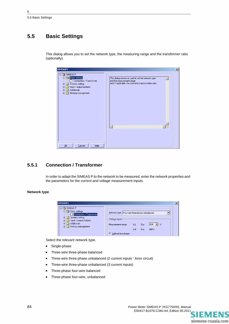
5
5.5 Basic Settings
5.5 Basic Settings
This dialog allows you to set the network type, the measuring range and the transformer ratio (optionally).
5.5.1 Connection / Transformer
In order to adapt the SIMEAS P to the network to be measured, enter the network properties and the parameters for the current and voltage measurement inputs.
Network type
Select the relevant network type.
• Single-phase
• Three-wire three-phase balanced
• Three-wire three-phase unbalanced (2 current inputs ' Aron circuit)
• Three-wire three-phase unbalanced (3 current inputs)
• Three-phase four-wire balanced
• Three-phase four-wire, unbalanced
84 Power Meter SIMEAS P 7KG7750/55, ManualE50417-B1076-C340-A4, Edition 05.2011

5
5.5 Basic Settings
Voltage inputsMeasurement range
Select the maximum voltage measurement range up to which the device should display. For Sin-gle-phase or three-wire three-phase networks, both the core and the phase voltage are dis-played here. The precision information for the device relates to the range selected here.
Without transformer
SIMEAS P can be operated without a voltage transformer up to a maximum of AC 690 V phase to phase.
With transformer (L-L)
If a voltage transformer is used, enter the primary and secondary data for the transformer here. The device measurement range is extrapolated internally by the factor of the transformation ratio.
Current inputsMeasurement range
Select the maximum current measurement range up to which the device should display. The pre-cision information for the device relate to the range selected here.
Without transformer
SIMEAS P can be operated without a current transformer up to a maximum of AC 6 A.
With transformer
If a current transformer is used, enter the primary and secondary data for the transformer here. The device measurement range is extrapolated internally by the factor of the transformation ratio.
85Power Meter SIMEAS P 7KG7750/55, ManualE50417-B1076-C340-A4, Edition 05.2011
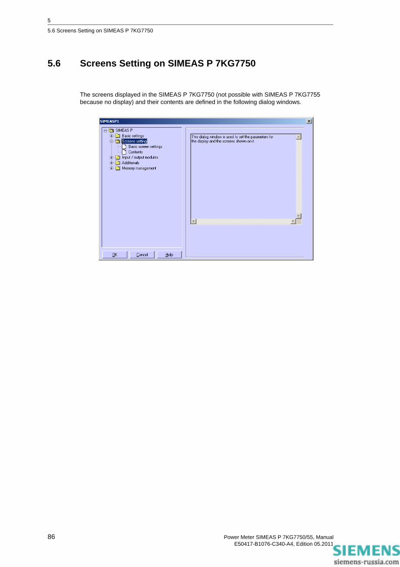
5
5.6 Screens Setting on SIMEAS P 7KG7750
5.6 Screens Setting on SIMEAS P 7KG7750
The screens displayed in the SIMEAS P 7KG7750 (not possible with SIMEAS P 7KG7755 because no display) and their contents are defined in the following dialog windows.
86 Power Meter SIMEAS P 7KG7750/55, ManualE50417-B1076-C340-A4, Edition 05.2011

5
5.6 Screens Setting on SIMEAS P 7KG7750
5.6.1 Basic Screen Settings
Here you define fundamental properties of the display on the SIMEAS P 7KG7750.
Number of screensSelect the number of screens, which can be selected using the buttons on the front of SIMEAS P. You can enter between 1 and 20 screens.
Automatic screen intervalIn SIMEAS P, you can switch between screens either manually using the buttons or automati-cally.
• 0 s (= Off): manual switching using keys
• 1 s to 60 s: automatic switching after the period set; the device then switches automatically from screen to screen on a loop.
Display illuminationYou can enter the time the backlighting remains on in minutes here.
• 0 min (= Off): no backlighting
• 1 min to 98 min: after a button is pressed on the device, the back lighting remains on for the time set.
• 99 min (= On): permanent backlighting
Display contrastHere, you can adjust the contrast of the SIMEAS P display. The default value is 4.
• Input options: 0 to 9
87Power Meter SIMEAS P 7KG7750/55, ManualE50417-B1076-C340-A4, Edition 05.2011

5
5.6 Screens Setting on SIMEAS P 7KG7750
5.6.2 Contents
Here you define the contents displayed in the individual screens.
To do this, select in field Screen contents the screen No. of the screen you wish to configure and assign it a screen type in the Content field. Screen types are predefined display formats for your measured values on the SIMEAS P display.
You can choose between the screen types:
• 3 Measured values digital
• 6 Measured values digital
• Min-Max values
• U, I, cos φ
For each screen type, further selection options are displayed.
• If you select 3 digital measured values, 6 digital measured values or Min - Max - values, the options are the measured values to be displayed and the measurement point.
• If you select U, I, cos phi no further settings are require in the basic version.
88 Power Meter SIMEAS P 7KG7750/55, ManualE50417-B1076-C340-A4, Edition 05.2011
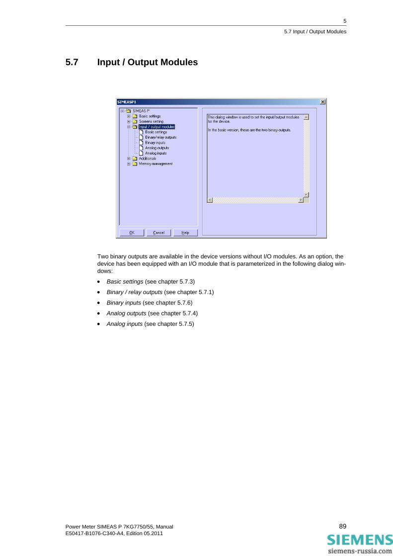
5
5.7 Input / Output Modules
5.7 Input / Output Modules
Two binary outputs are available in the device versions without I/O modules. As an option, the device has been equipped with an I/O module that is parameterized in the following dialog win-dows:
• Basic settings (see chapter 5.7.3)
• Binary / relay outputs (see chapter 5.7.1)
• Binary inputs (see chapter 5.7.6)
• Analog outputs (see chapter 5.7.4)
• Analog inputs (see chapter 5.7.5)
89Power Meter SIMEAS P 7KG7750/55, ManualE50417-B1076-C340-A4, Edition 05.2011

5
5.7 Input / Output Modules
5.7.1 Binary / Relay Outputs
The SIMEAS P has two binary outputs. The devices are optionally equipped with a module with 3 additional relay outputs or a module with two binary outputs each.
In order to define the function of the two binary/relay outputs, select the binary output to be parameterized in field Binary outputs → No. In the Contents field, you can assign this binary output a function. You can select from the following options:
• Off: binary output with no function
• Device active: The SIMEAS P active function allows you to monitor whether the device is switched on (contact closed). If there is no contact, the device is switched off or broken.
• Limit values: Here, you can output the limit value group signals via the binary outputs. The pulse length indicates how long the binary contact is closed by means of a signal from a limit value group.
• Energy counter: If you assign this function to a binary output, the consumption or supply of the selected work is output as a pulse. Select a measured value and the related measure-ment point. Set a limit value (energy increase per pulse) for which a pulse should be trig-gered. The parameterizable range (minimum and maximum value) can be found by entering the max. consumer power in the field Help. The pulse duration can be selected in increments of 50 ms between 50 ms and 500 ms in the Pulse field .
You will find a description of the energy pulse measurement in chapter 5.7.2.
• Direction of rotation: output the rotation direction of the voltage
• 1: Contact activated: Direction of rotation for clockwise display (phase sequence A-B-C, clockwise rotation)
• 0: Contact deactivated: Direction of rotation for anti-clockwise display (2 phases inter-changed, anti-clockwise rotation)
90 Power Meter SIMEAS P 7KG7750/55, ManualE50417-B1076-C340-A4, Edition 05.2011

5
5.7 Input / Output Modules
5.7.2 Information on Energy Pulse Measurement
The binary outputs of the SIMEAS P may be used to generate impulses for energy measure-ment: You can parameterize a specific amount of energy. When this threshold is reached, a defined pulse will be applied to the output. For energy pulse measurement, you have to adjust several settings at the device and in the parameterization software.
5.7.2.1 Parameterization via Device
Refer to chapter 4.4.3.
5.7.2.2 Pulse Time, Switch Off Time, Number of Pulses
• Pulse time (Pulse): Defines the "high" time of the signal at the binary output; possible values: 50 ms to 500 ms.
• Switch off time: Time during which the signal at the output of the binary contact is "low". The switch off time depends on the power measured.
• Minimum switch off time: The minimum switch off time must not be smaller than 50 ms to reach a defined switch off time.
• Number of pulses: The minimum pulse length and the minimum switch off time define the fol-lowing maximum number of impulses per hour:
Pulse time(50 ms to 500 ms)
Switch off time≥ 50 ms
Minimum period time
Pulse time(ms)
Minimum switch off time (ms)
Minimum period time (ms)
Max. number of pulses / h
50 ≥ 50 100 36000
100 ≥ 50 150 24000
150 ≥ 50 200 18000
200 ≥ 50 250 14400
250 ≥ 50 300 12000
300 ≥ 50 350 10286
350 ≥ 50 400 9000
400 ≥ 50 450 8000
450 ≥ 50 500 7200
500 ≥ 50 550 6545
91Power Meter SIMEAS P 7KG7750/55, ManualE50417-B1076-C340-A4, Edition 05.2011

5
5.7 Input / Output Modules
5.7.2.3 Parameterization of Energy Pulses
If you want to use the binary outputs for energy measurement, you have to calculate the smallest possible input (kWh/pulse) first. Please use the following description:
1. Select the pulse length (e.g. 200 ms). Refer to the table in chapter 5.7.2.2 for the maximum number of pulses/h: 14400
2. Calculation of the maximum load to be connected:
Single-phase circuit: Maximum load to be connected =
(Voltage measuring range Ph-N x Transformation ratio of the voltage transformer) x (Cur-rent measuring range x Transformation ratio of the current transformer)
e.g.: UPh-N, max = 276 V, TU = 1; Imax = 1.2 A, TI = 1
Pmax = UPh-N, max x Imax = 331.2 W
Three-phase or four-phase circuit: Maximum load to be connected = (Voltage measuring range Ph-N x Transformation ratio of the voltage transformer) x (Current measuring range x Transformation ratio of the current transformer) x 3
e.g.: UPh-N, max = 276 V, TU = 1; Imax = 1.2 A, TI = 1
Pmax = (UPh-N, max x Imax) x 3 = 993.6 W
3. Calculation of the minimum energy increase per pulse
Depending on the pulse length and the maximum number of pulses/h the following calcula-tion applies:
Singl-phase circuit:
Pmax/W / 14400 puls/h = 331.2 W / 14400 puls/h =
0.023 Wh/puls = 0.000023 kWh/puls
Three-phase or four-phase circuit:
Pmax/W / 14400 puls/h = 993.6 W / 14400 puls/h =
0.069 Wh/puls = 0.000069 kWh/puls
For the example, the smallest energy increase is as follows:
Singl-phase circuit: 0.000023 kWh/puls
Three-phase or four-phase circuit: 0.000069 kWh/puls
If you use a setting higher than these values the increase of energy will be registered cor-rectly.
Note
The smallest possible input values only apply if the connected load is close to the threshold of the measuring range of the device. If the connected load is smaller, the calculated values may also be smaller.
Note
A transformation ratio >1 has to be used in the calculation described above and in the parame-terization of the device.
92 Power Meter SIMEAS P 7KG7750/55, ManualE50417-B1076-C340-A4, Edition 05.2011

5
5.7 Input / Output Modules
5.7.2.4 Parameterization of Energy Pulses via Parameterization Software
To parameterize energy impulses via parameterization software (refer also to chapter 5.7.1), proceed as follows:
1. Select the Measured value to be counted.
2. 2.Select the Test point for the energy measurement.
3. Select the Pulse length for the signal.
4. Calculate the smallest energy increase per pulse. Use the description in chapter 5.7.2.3 to calculate the minimum value.
You can use the Help field in the dialog window for the calculation. For this purpose, enter the connected consumer power in the kW in total field. Then switch over to another field of this dialog window to update the display. The smallest possible power increase per pulse for the connected consumer power you have entered is displayed in the Help field under Input can be in range.
5. For the value entered in the field Energy increase per pulse, a pulse will be applied to the selected output each time when the given value will be reached
Note
Smallest pulse length = 50 ms.
Note
When you open the dialog for the first time, default values will be displayed. These values are derived from the connection type (single-phase, three-phase or four-phase circuit), the voltage and current range and the transformer ratios
The default values are only valid when you open the dialog for the first time!
93Power Meter SIMEAS P 7KG7750/55, ManualE50417-B1076-C340-A4, Edition 05.2011

5
5.7 Input / Output Modules
5.7.3 Basic Settings
This dialog allows you to specify the I/O module (optionally) of your SIMEAS P.
There are two possibilities:
SIMEAS P is connected with PC (online)1. Click the button Load slot configuration from device. The information will be loaded from
the device and displayed on the screen.
2. Parameterize the I/O modules.
3. Send the new configuration to the device.
A parameter set is prepared for a later transmission to a SIMEAS P (offline).1. Define slot A for the corresponding I/O module.
Note
To ensure proper energy registration, this value must not be lower than the value calculated in step 4.
Note
This procedure ensures that the I/O modules displayed on the screen correspond to those in the device.
Note
These settings must correspond to the I/O modules in the device (refer to the ordering number, see chapter 1.2)!
94 Power Meter SIMEAS P 7KG7750/55, ManualE50417-B1076-C340-A4, Edition 05.2011

5
5.7 Input / Output Modules
2. Parameterize the I/O modules.
3. Send the new configuration to the device, as soon as the connection to the device has been established.
5.7.4 Analog Outputs (optional)
The analog outputs (optional) allow you to output internal measurement values as analog values in the range of 0 mA to 20 mA. This feature represents a measuring transducer.
Proceed as follows:
1. Please select Slot A to configure analog outputs.
2. Activate/Deactivate one or both analog outputs by ticking the corresponding check box under 1. and/or 2.
3. For each analog output used, choose the Measured value together with the Test point and set the signal range in the fields from and to.
4. Select the current range of the I/O module: 0..20 mA or 4..20 mA.
Note
The output of analog values can be controlled via Modbus, IEC 60870-5-103 or Profibus proto-col. Select the output mode first in screen further setting (see chapter 4.4.8) in AO settings and choose holding or default mode in screen Analog output settings.
Deactivate the channel which will be controlled by communication protocol in dialog Analog out-puts.
95Power Meter SIMEAS P 7KG7750/55, ManualE50417-B1076-C340-A4, Edition 05.2011

5
5.7 Input / Output Modules
5.7.5 Analog Inputs (optional)
The analog inputs (optional) allow you to measure analog signals in the range of 0 mA to 20 mA.
Proceed as follows:
1. Activate/Deactivate one or both analog inputs by ticking the corresponding check box under 1. and/or 2.
2. For each input used, set the Designation together with the Dimension (max. 6 characters).
3. You define the range of values of the signal in the fields from and to.
4. The device display will be parameterized via screen contents, the supervision of limit values concerning the analog inputs via limit value groups.
Note
It is possible to save the values (together with the time information) recorded via analog inputs to the memory for mean values (see chapter 5.9.2).
96 Power Meter SIMEAS P 7KG7750/55, ManualE50417-B1076-C340-A4, Edition 05.2011

5
5.7 Input / Output Modules
5.7.6 Binary Inputs (optional)
The binary inputs (optional) can be used for static messages and impulse inputs.
Proceed as follows:
1. Activate/Deactivate one or both binary inputs by ticking the corresponding check box under 1. and/or 2.
2. For each input used, set the Designation together with the Dimension.
3. If you want to use the input as an external counter, you have to define the Factor e.g. as Energy increase per pulse (refer to chapter 5.7.2).
4. If you want to use the binary input to display binary information (0/1), 0 must be entered as a factor.
5. Choose the binary input to be used for time Synchronization via minute impulses. The device will display the designation, not the number of the Binary input.
6. Analog to measured values, binary inputs may be displayed on measurement screens (see chapter 5.6.2).
Note
The designation of the binary input is displayed instead of the binary input number!
97Power Meter SIMEAS P 7KG7750/55, ManualE50417-B1076-C340-A4, Edition 05.2011

5
5.8 Additionals
5.8 Additionals
All other settings in SIMEAS P are made in the following windows.
Options• Regional settings, such as device language and measured value descriptor
• Type of power calculation
• Direction of current
• Power direction
• Counter assignment of digital counter in screens
• Zero point suppression
Device codeSetting device codes to secure the device settings against unauthorized changes.
Limit value groupsThe 7 limit value groups for the device can be set here.
Clock ChangeHere you can set the data for daylight saving time switchover.
98 Power Meter SIMEAS P 7KG7750/55, ManualE50417-B1076-C340-A4, Edition 05.2011

5
5.8 Additionals
5.8.1 Options
You can set more parameters for the SIMEAS P under Options.
Regional settings• Language: Here, you can select what language the device display is in when you parame-
terize it using the device buttons.
• Measured value designation: The description of the conductor on device L1/L3/L3 or A/B/C can be selected here.
Power calculationHere, you can select the type of power calculation and the calculation for current and voltage. The basic setting is standard. Settings options:
• Standard: All measured values are true RMS, taking all harmonics into consideration. Cal-culation of reactive power using methods used by traditional measuring devices. (electrody-namics power measurement)
• DIN: All measured values are true RMS, taking all harmonics into consideration. Customized from standard: reactive power calculation, apparent power calculation, cos φ and power fac-tor, taking into consideration the new definition of apparent power in: DIN 40110-2.
• Fourier: All measured values calculated from the fundamental wave. Harmonics are not con-sidered.
Direction of current• Standard: Default setting for correct connection according to standard and back panel mark-
ing
• Inverse: Current direction is negated (change the current direction to avoid changing theconnectors).
99Power Meter SIMEAS P 7KG7750/55, ManualE50417-B1076-C340-A4, Edition 05.2011

5
5.8 Additionals
Power directionThis parameter allows you to set the operating mode of the SIMEAS P:
• Load (industry mode, standard)
this means:Power positive = Energy demand
Power negative = Energy supply
• Generator (Power generation mode)
this means:Power negative = Energy demand
Power positive = Energy supply
Counter assignmentInternal counters 1 to 4 can be displayed in the digital measured value screens of the SIMEAS P. You can assign the four internal counters to the max. 6 limit values groups here.
Zero point suppressionThe zero suppression enables the definition of the measuring range start in % of the measuring range end. Can be selected from 0.0 % to 10.0 % of the upper limit of the measurement range (default setting: 1.000 %).
5.8.2 Device Code
Setting the device code secures the SIMEAS P against unauthorized changes.
When the code is activated, you are prompted to enter the password when you call up the
Note
Due to its high precision, SIMEAS P can measure voltages and currents even without measuring values connected to the device. If you do not want this behaviour in your application, you can suppress measuring below a certain threshold.
100 Power Meter SIMEAS P 7KG7750/55, ManualE50417-B1076-C340-A4, Edition 05.2011

5
5.8 Additionals
parameterization menu from the buttons on the device. The relevant menu is only enabled if you enter the correct password.
Code 1• without: no security
• with: device code 1 is only active if code 2 is activated as well.
Functions secured: screen parameterization, reset energy min / max values and changing device language.
Code 2• without: no security (code 1 also deactivated)
• with: code is activated
Saved functions: basic parameters (connection / transformers, outputs, interface, change code, adjustment, other settings)
Notes:• A password always consists of a 6-digit number.
• If you forget your password, you can activate the machine either using a master password (available from the hotline, see Foreword) or using the SIMEAS P parameterization software.
• Device code 1 is only active if code 2 is activated as well.
• If code 1 and 2 are activated, the code 2 password can also be used to unlock all the func-tions secured using code 1.
• If the secured parameter settings are called up in SIMEAS P, a window appears asking you to enter a password.
• If a secured parameter is unlocked by entering a password on the device, a new password prompt appears after a wait of 1 minute in level 1.
Note
The software does not require a password.
101Power Meter SIMEAS P 7KG7750/55, ManualE50417-B1076-C340-A4, Edition 05.2011

5
5.8 Additionals
5.8.3 Limit Value Groups
In SIMEAS P, you can parameterize up to 7 limit value groups. For limit value group 7, only volt-ages are allowed.
Every limit value group provides the option to monitor whether the measurements exceed (>) or fall short of (<) a measured value that is entered. In each of the seven limit value groups, up to six measured quantities (no power quantities) can be ANDed or ORed.
The limit value groups set can be allocated either to binary outputs or to the internal counters. The oscilloscope can be triggered using a limit value group 1 to 6.
• Filter time: Time for which a threshold breach must remain in order to trigger an alarm. Input from 0.0 s to 9.9 s.
• Hysteresis: Entry from 0.1 % to max. 10 %. The value relates to the nominal values for the individual measured values.
Note
To make sure that limit violations will be registered, enter a filter time ≥ 1 s.
Note
If the device provides additional analog inputs (optional), you can use external measurement sig-nals for limit-value monitoring.
Note
Limit value group 7 allows you to monitor the measured voltages in real time and logs the mea-sured value that caused a limit violation.
102 Power Meter SIMEAS P 7KG7750/55, ManualE50417-B1076-C340-A4, Edition 05.2011

5
5.8 Additionals
5.8.4 Clock Change
Select the date (day/month) when daylight saving time will start and end.
You do not have to indicate the hour since SIMEAS P considers the fact that the time change (Day / Mon.) will always take place at 2 a.m.
If you have not entered a date for start and end of the daylight saving time, the corresponding field remains grayed and SIMEAS P assumes that no time change will take place in the device. The time change will only be carried out if the corresponding date field is activated.
103Power Meter SIMEAS P 7KG7750/55, ManualE50417-B1076-C340-A4, Edition 05.2011

5
5.9 Memory Management
5.9 Memory Management
In the following dialog windows, you can customize the memory of SIMEAS P according to your requirements.
104 Power Meter SIMEAS P 7KG7750/55, ManualE50417-B1076-C340-A4, Edition 05.2011

5
5.9 Memory Management
5.9.1 Splitting
In this dialog window you can determine how the available memory capacity will be allocated to the available functions.
Note
The indicated percentages must be in the range between 1 and 96 percent and total 100 %. Once you have entered a percent value, SIMEAS PAR displays to its right the recording time and the number of values that will be stored for this setting. The oldest values will be overwritten if you have selected Ring buffer = Yes for the recording or if overwriting is enabled by default. If you have selected Ring buffer = No, the recording will be terminated when the capacity of the associated memory area is exhausted. See the next chapters for details.
Note
The device has a memory capacity of 1 MByte (= 1048576 Bytes). The default setting ex works is 20 % of the total memory capacity for each of the five memory areas. With this memory parti-tion, the theoretical memory capacity is 200 KBytes (exactly: 209715 Bytes) per memory area.
105Power Meter SIMEAS P 7KG7750/55, ManualE50417-B1076-C340-A4, Edition 05.2011

5
5.9 Memory Management
The recording capacities will be calculated according to the following formulas:
Mean values
n: Number of channels (max. 8)
Period time: 5 s, 10 s, 15 s, 30 s, 60 s, 600 s, 900 s, 1800 s or 3600 s
Calculation example with 20 % memory size, n = 8 channels and period time = 10 s
Power values
n: Number of channels (max. 8)
Period time: 15 min, 30 min or 60 min
Calculation example with 20 % memory size, n = 8 channels and period time = 15 min
Note
For technical reasons (e.g., capacity for header data), the recording capacity for the individual measured values displayed in the dialog window is slightly smaller than the capacity in the exam-ples.
3600*)4)12*((*][][
BytenPeriodtimeByteemoryAllocatedMhtMAX +
=
209715 Byte * 10
((8 * 12) + 4) Byte * 3600tMAX (h) = = 5.8 h
1440*)6)4*((*][][
BytenPeriodtimeByteemoryAllocatedMdt MAX +
=
209715 Byte * 15
((8 * 4) + 6) Byte * 1440tMAX (d) = = 60 d
106 Power Meter SIMEAS P 7KG7750/55, ManualE50417-B1076-C340-A4, Edition 05.2011

5
5.9 Memory Management
Oscilloscope: Instantaneous values
Calculation example with 20 % memory size
Oscilloscop: RMS values
Calculation example with 20 % memory size
Limit violations
Calculation example with 20 % memory size
50*16*64][][
ByteByteemoryAllocatedMstMAX =
209715 Byte
64 * 16 Byte * 50tMAX (s) = = 4,1 s
3600*8][][
ByteByteemoryAllocatedMhtMAX =
209715 Byte
8 Byte * 3600tMAX (h) = = 7 h
ByteByteemoryAllocatedMValues
12][
=
209715 Byte12 ByteValues = = 17476
107Power Meter SIMEAS P 7KG7750/55, ManualE50417-B1076-C340-A4, Edition 05.2011

5
5.9 Memory Management
Binary states
Calculation example with 20 % memory size
5.9.2 Mean Values
In this dialog window you can specify the settings for mean value recording.
Proceed as follows:
1. Select up to eight Measured values and Test points.
2. Select a Date or one of the six Limit value groups as Start selector for the average value recording. It is possible to combine Date and Limit value group as start selectors. The first of the two criteria fulfilled, will launch the recording.
3. When entering a date as Start selector, you must indicate a year between 2000 and 2060.
4. The Ring buffer mode allows you to select, if the oldest values will be overwritten (= Yes) or not (= No) when the capacity of the associated memory area is exhausted.
ByteByteemoryAllocatedMValues
8][
=
209715 Byte8 ByteValues = = 26214
108 Power Meter SIMEAS P 7KG7750/55, ManualE50417-B1076-C340-A4, Edition 05.2011

5
5.9 Memory Management
5. Also, you must indicate the Averaging interval (5 s, 10 s, 15 s, 30 s, 1 min, 5 min, 10 min, 15 min, 30 min, 60 min) and the Storage interval (5 s, 10 s, 15 s, 30 s, 1 min, 5 min, 10 min, 15 min, 30 min, 60 min). These parameters set the number of measured values to be used for mean value calculation and the interval for saving the values.
5.9.3 Power Values
In this dialog window you can specify the settings for power recording.
Proceed as follows:
1. Select up to eight Measured values and Test points.
2. Select a Date or one of the six Limit value groups as Start selector for the power recording. It is possible to combine Date and Limit value group as start selectors. The first of the two criteria fulfilled, will launch the recording.
3. When entering a date as Start selector, you must indicate a year between 2000 and 2060.
Note
If you have entered a past start date, SIMEAS P will initiate mean value recording immediately after the setting. Manual start is not activated by configuration but can be initiated at any time.
Note
If the device provides additional analog inputs (optional), you can record external measurement signals.
109Power Meter SIMEAS P 7KG7750/55, ManualE50417-B1076-C340-A4, Edition 05.2011

5
5.9 Memory Management
4. The Ring buffer mode allows you to select, if the oldest values will be overwritten (= Yes) or not (= No) when the capacity of the associated memory area is exhausted.
5. Also, you must indicate the Period time (15 min, 30 min, 60 min).
Note
If you have entered a past start date, SIMEAS P will initiate mean value recording immediately after the setting. Manual start is not activated by configuration but can be initiated at any time.
110 Power Meter SIMEAS P 7KG7750/55, ManualE50417-B1076-C340-A4, Edition 05.2011

5
5.9 Memory Management
5.9.4 Oscilloscope
• The oscilloscope is parameterized using SIMEAS P Par.
• Three measured quantities are always recorded.
• Normally, 30 % of the recording is allocated to pre-triggering history.
• Only one recording is possible. When initiating a new recording, the previous one is deleted.
• When triggering the oscilloscope via limit violation, the recording can also be executed in the background.
• Only the first of several limit violations that trigger a recording is recorded. Further violations are ignored.
5.9.4.1 Characteristics of „Instantaneous Values“ Recording
Record length can be parameterized. The recording time to be saved in the allocated memory (see chapter 5.9.1) is calculated according to the following formula:
Sampling rateThe sampling rate is adjusted such that there are 64 samples per cycle. Therefore, the sampling rate is as follows for 50 Hz and 60 Hz respectively:
• at 50 Hz = 3.20 kHz
• at 60 Hz = 3.84 kHz
Trigger via Limit ViolationThe RMS value of each half wave is calculated and tested for Max/Min violations. If a violation is detected, recording is triggered immediately. The bandwidth and filter time settings are irrele-vant here.
Note
The memory range can be set by the user.
50*16*64][][
ByteByteemoryAllocatedMstMAX =
Note
The recording type "Instantaneous value" allows to record the measurement values "current" and "voltage" only.
111Power Meter SIMEAS P 7KG7750/55, ManualE50417-B1076-C340-A4, Edition 05.2011

5
5.9 Memory Management
5.9.4.2 Characteristics of "RMS Value" Recording
• Any three measured quantities can be selected from the Table 3-1 with the exception of energy values and counters.
Recording timeRecording time can be parameterized. The recording time to be saved in the allocated memory (see chapter 5.9.1) is calculated according to the following formula:
• One sample of a measured quantity is saved each second.
• Pre-trigger history is always 30 % of the selected recording time.
3600*8][][
ByteByteemoryAllocatedMhtMAX =
Note
• Since 30 % of the recording time is always allocated to pre-trigger history, the time for record-ing the pre-trigger history must expire before a new recording can be triggered.
• The recording type "RMS Value" does not allow to record analog inputs (optional).
112 Power Meter SIMEAS P 7KG7750/55, ManualE50417-B1076-C340-A4, Edition 05.2011

5
5.9 Memory Management
5.9.5 Parameterization Oscilloscope
The oscilloscope can be set via this dialog window.
Proceed as follows:
1. Select up to three measured quantities: An oscilloscope recording is started via the selected limit value group (groups 1 to 6 are allowed).
2. Also, you must determine whether to record Instantaneous values or RMS values.
3. The Ring buffer mode allows you to select, if the oldest values will be overwritten (= Yes) or not (= No) when the capacity of the associated memory area is exhausted.
4. Indicate the Storage duration in seconds.
Note
When changing the value type (instantaneous or RMS), the present selection will be reset since the two types of measured values have different value ranges.
Note
In the submenu Memory management → Splitting you can see what storage time corresponds to the indicated percentage for oscilloscope.
113Power Meter SIMEAS P 7KG7750/55, ManualE50417-B1076-C340-A4, Edition 05.2011

5
5.9 Memory Management
5.9.6 Limit Violation
In this dialog window you can specify the limit value groups to be recorded.
Select up to six Limit value groups. A violation of the specified limits will be recorded in the memory.
Note
If the memory capacity for the recording of limit violations is exhausted, data within this area will be overwritten.
114 Power Meter SIMEAS P 7KG7750/55, ManualE50417-B1076-C340-A4, Edition 05.2011

5
5.9 Memory Management
5.9.7 Binary States
In this dialog window you can specify the settings for recording of binary states.
Select the Binary outputs to be recorded. The states of the binary outputs will then be recorded in the memory.
115Power Meter SIMEAS P 7KG7750/55, ManualE50417-B1076-C340-A4, Edition 05.2011

5
5.10 Updating the Firmware
5.10 Updating the Firmware
Proceed as follows to update the firmware:
1. Establish a connection to the device. From the menu bar, select Connection → Setup con-nection and set the following parameters in the Setup device connection dialog:
• Device connection: Serial connection
• Device address: address 0 is valid for all devices
• Interface: e.g. COM1
• Baud rate: 9600 Baud at delivery
• depends on adapter type RS485
2. Confirm by clicking OK.
Note
Make sure to set the same parameter values in SIMEAS P Parameterization and in the device. In the device, the serial interface must be set to "PC-RS 485".
116 Power Meter SIMEAS P 7KG7750/55, ManualE50417-B1076-C340-A4, Edition 05.2011

5
5.10 Updating the Firmware
3. Query the device identification once to check the connection. To do this, click the ID symbol in the toolbar.
4. Click the Receive Identification button to retrieve data from the device. If the configuration is correct, all lines are filled with device data. Close the dialog window.
5. From the menu bar, select Device → Send new firmware.
6. In the Send firmware dialog, enter the path to the firmware (file 7KG*.SX)
7. Click the button Transmit firmware. The transfer may take some minutes. Check the ID again (symbol ID, see item 3). The new firmware version will be displayed.
Note
A check sum allows to relate each firmware version to device types and hardware versions. This ensures that no incompatible hardware and software version are updated. In this case, the trans-fer will be terminated with the message "Timeout while waiting for reply from device". The original firmware in the device remains unchanged.
117Power Meter SIMEAS P 7KG7750/55, ManualE50417-B1076-C340-A4, Edition 05.2011

5
5.11 Resetting Values in the Device
5.11 Resetting Values in the Device
SIMEAS P Parameterization allows you to reset the following values:
• Energy counter
• Counters for limit violations
• Min, aver and max values
Proceed as follows:
1. Establish a connection to the device. Make sure to set the same parameter values in SIMEAS P Parameterization and in the device. In the device, the serial interface must be set to "PC-RS 485".
2. From the menu bar, select Device → Commands → Reset values to reset the displayed items.
118 Power Meter SIMEAS P 7KG7750/55, ManualE50417-B1076-C340-A4, Edition 05.2011
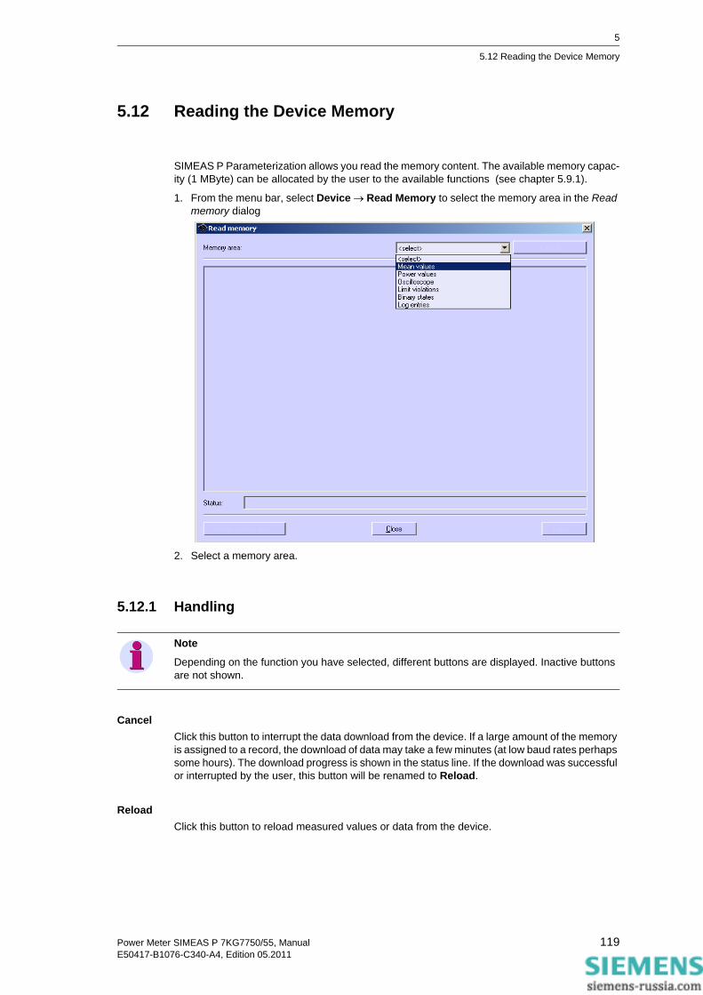
5
5.12 Reading the Device Memory
5.12 Reading the Device Memory
SIMEAS P Parameterization allows you read the memory content. The available memory capac-ity (1 MByte) can be allocated by the user to the available functions (see chapter 5.9.1).
1. From the menu bar, select Device → Read Memory to select the memory area in the Read memory dialog
2. Select a memory area.
5.12.1 Handling
CancelClick this button to interrupt the data download from the device. If a large amount of the memory is assigned to a record, the download of data may take a few minutes (at low baud rates perhaps some hours). The download progress is shown in the status line. If the download was successful or interrupted by the user, this button will be renamed to Reload.
ReloadClick this button to reload measured values or data from the device.
Note
Depending on the function you have selected, different buttons are displayed. Inactive buttons are not shown.
119Power Meter SIMEAS P 7KG7750/55, ManualE50417-B1076-C340-A4, Edition 05.2011

5
5.12 Reading the Device Memory
CloseClick this button to terminate the dialog window Read memory.
ExportClick this button to save measured values or information as CSV file (Comma separated values) or COMTRADE file (IEEE Standard Common Format for Transient Data Exchange). CSV files can be read and processed, e.g., with Excel. COMTRADE files are used for exchanging mea-sured data as documented in the IEEE Std C37.111-1999. The standardization includes both the format for measuring files and the type of media used for the exchange of fault report, test or simulation data of power supply systems.
Delete memory areaClick this button to delete the selected memory area in the device. Optionally, you can restart the recording immediately or with the occurring of a parameterized trigger condition (mean values, power values, and limit violations only).
5.12.2 Charts / Diagrams
Diagrams and charts are coupled: By moving the measuring cursor in the diagram, the corre-sponding row in the chart is marked; by activating a row in the chart, the cursor in the diagram moves to the corresponding timestamp (mean values, power values, and binary states only).
5.12.3 Diagrams
In diagrams, zooming, measuring and other functions are available. Click the right mouse button in diagrams to activate the functions zoom, optimize, optimize x-axis, optimize y-axis, diagrams (fade in or blind out diagram for measured value), signals (fade in or blind out diagram for mini-mum, mean respectively maximum value) and copy diagrams in selectable size to the clipboard (mean values, power values, binary states, and oscilloscope data only).
5.12.4 Timestamps
All timestamps are shown in regional normal time. This avoids time gaps or overlap in data (for example, when summer time starts or ends).
5.12.5 Mean Value Record
Mean values are represented in a chart and in diagrams. In the chart, you can select between minimum values, mean values and maximum values in headline. For each recorded mean value (max. 8), one column in the chart and one diagram is shown. In the diagram, the mean value and the tolerance area limited by minimum and maximum value are drawn.
120 Power Meter SIMEAS P 7KG7750/55, ManualE50417-B1076-C340-A4, Edition 05.2011

5
5.12 Reading the Device Memory
5.12.6 Power Value Record
Power values are represented in a chart and in diagrams. For each recorded power value (max. 8), one column in the chart and one diagram is shown.
5.12.7 Oscilloscope
Records of oscilloscope are represented in one diagram for each value with trigger timestamp. With the two measuring cursors measurement on signals is possible. To do this, select signals in the table. Additional functions are available by pressing the right mouse button (see diagrams).
5.12.8 Limit Violation Record
Limit violations are represented in a chart. Limit violations of group 1 to 6 are shown when occur-ring (ON) and disappearing (OFF). For limit violation group 7, additional information is available: the signal on which the violation occurred and the measured value appeared.
121Power Meter SIMEAS P 7KG7750/55, ManualE50417-B1076-C340-A4, Edition 05.2011

5
5.12 Reading the Device Memory
5.12.9 Binary States
Binary states are represented in a chart and in diagrams. For each recorded binary state, one column in the chart and one diagram is shown.
5.12.10 Log Entries
Log entries are represented in a chart. For each of the following entries, date and time are shown:
• Failure voltage supply
• Switch on auxiliary power supply
• Change of device parameter
• Reset recording limit value groups
• Reset recording mean values
• Reset recording power values
• Reset recording oscilloscope
• Set watch
Note
For further information on "Reading the Device Memory", refer to the online help of the PC pro-gramming software (press F1).
122 Power Meter SIMEAS P 7KG7750/55, ManualE50417-B1076-C340-A4, Edition 05.2011

5
5.13 Changing the Communication Parameters
5.13 Changing the Communication Parameters
At delivery, the following communication parameters are preset:
• Address: 1
• Protocol: Serial ASCII
• Baud rate: 9600 bit/s
• Parity: No
In order to switch to another protocol, proceed as follows:
1. From the menu, select Device → Connection configuration → Edit. The dialog Device connection parameters will open.
2. Select the combination of bus protocols supported by your device in the bus protocols in the device field:
• PROFIBUS DP and Modbus or
• IEC 60870-5-103 and Modbus
123Power Meter SIMEAS P 7KG7750/55, ManualE50417-B1076-C340-A4, Edition 05.2011

5
5.13 Changing the Communication Parameters
3. Select the required protocol type depending on the bus protocol used:
PROFIBUS DP and Modbus IEC 60870-5-103 and Modbus
- Serial ASCII - Serial ASCII
- Profibus DP - IEC 60870-5-103
- Modbus ASCII - Modbus ASCII
- Modbus RTU - Modbus RTU
4. Set the Address of the device and (if required) the Baud rate and the Parity.
5. If you have selected the IEC 60870-5-103 protocol, the following IEC 60870-5-103-specific parameters are activated, where you have to choose :
• Measured values range: 120 % or 240 %
• Transmit harmonics: Yes or No
• Transmit energy and counters: Yes or No
6. Confirm your entries by clicking OK.
7. Select the menu item Device→ Connection configuration → Send to send the new setting to the device.
Note
The bus protocols provided in your device depend on the device type and the firmware ver-sion.Therefore, check the correct bus protocol combination of your device.
Note
The settings will not be activated in the device unless a hardware reset has been made.
After the device has been switched on, you have got 60 seconds to establish a connection to the parameterization tool. Once this time has elapsed, the communication protocol set will be acti-vated automatically.
124 Power Meter SIMEAS P 7KG7750/55, ManualE50417-B1076-C340-A4, Edition 05.2011

Calibration 6 Contents
The adjustment is explained in the following chapters.
6.1 Overview 126
6.2 Connection Diagrams for Adjustment 127
6.3 Procedure 128
125Power Meter SIMEAS P 7KG7750/55, ManualE50417-B1076-C340-A4, Edition 05.2011

6
6.1 Overview
6.1 Overview
SIMEAS P can be adjusted either directly from the device using the buttons on the front panel or by using the SIMEAS P programming software.
You can select the measurement range under Basic Settings → Connection / Transformer. Only the measurement ranges selected for current and voltage inputs can be adjusted in the Cal-ibration menu.
Adjusting the SIMEAS P requires a single-phase adjusting device that can generate voltages and currents to an accuracy of ≤ 0.1 %, e.g. Omicron CMC 156. Adjustment frequency: 50 Hz or 60 Hz.
When connecting the adjusting outputs to the appropriate inputs, make sure that the SIMEAS P is correctly connected as per the Connection Diagrams for adjustment.
The following three elements should be adjusted during the adjustment process:
• Voltage inputs V
• Current inputs I
Note
To be able to make adjustments using the software, a connection must be established between the PC and the SIMEAS P device.
Before starting the adjustment, you should set the time in the SIMEAS P. This ensures that the last adjustment is displayed with a date in the SIMEAS P.
126 Power Meter SIMEAS P 7KG7750/55, ManualE50417-B1076-C340-A4, Edition 05.2011
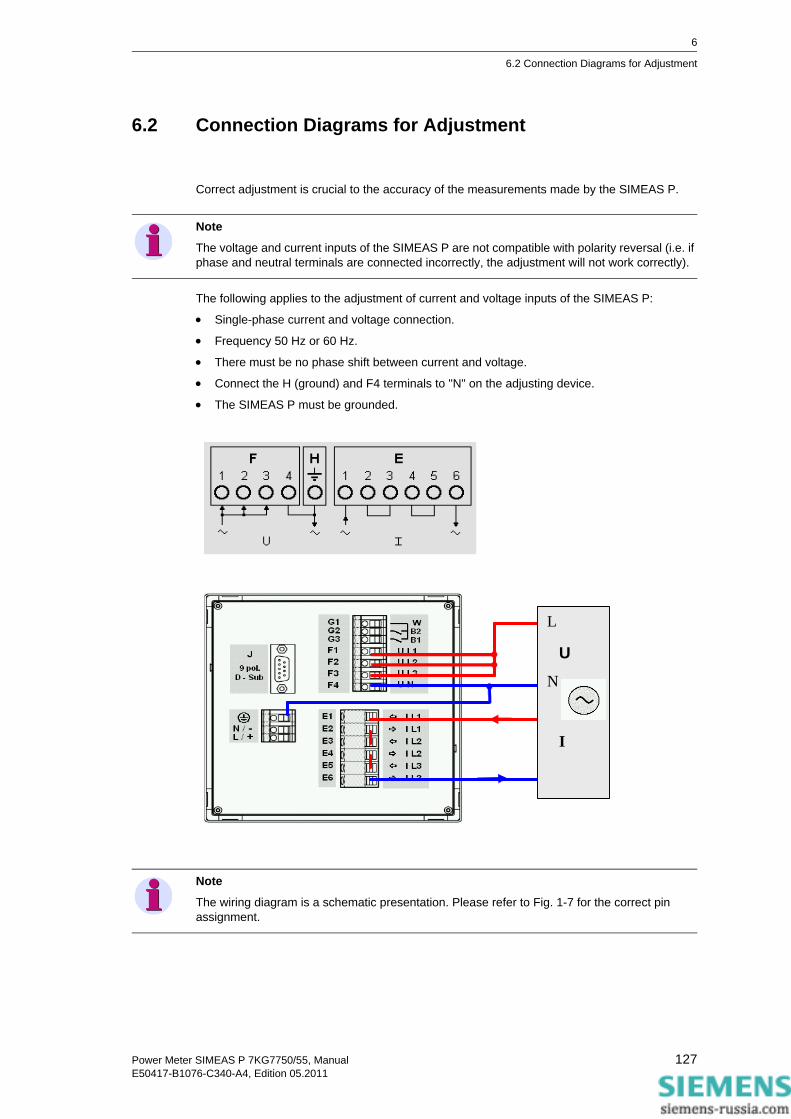
6
6.2 Connection Diagrams for Adjustment
6.2 Connection Diagrams for Adjustment
Correct adjustment is crucial to the accuracy of the measurements made by the SIMEAS P.
The following applies to the adjustment of current and voltage inputs of the SIMEAS P:
• Single-phase current and voltage connection.
• Frequency 50 Hz or 60 Hz.
• There must be no phase shift between current and voltage.
• Connect the H (ground) and F4 terminals to "N" on the adjusting device.
• The SIMEAS P must be grounded.
Note
The voltage and current inputs of the SIMEAS P are not compatible with polarity reversal (i.e. if phase and neutral terminals are connected incorrectly, the adjustment will not work correctly).
U
I
L
N
Note
The wiring diagram is a schematic presentation. Please refer to Fig. 1-7 for the correct pin assignment.
127Power Meter SIMEAS P 7KG7750/55, ManualE50417-B1076-C340-A4, Edition 05.2011

6
6.3 Procedure
6.3 Procedure
• First, connect the SIMEAS P as described in chapter 6.2.
• You can adjust the device manually or via programming software
Procedure at the device• Select Basic settings → Connection / Transformer.
Select the range to be adjusted (e.g. AC 228 V).
• In the menu, select: Calibrate.
A dialog window appears.
• Enter the setpoint value for adjustment voltage and adjustment current. Default setpoints are the nominal ranges of the measuring ranges set under Connection / Transformer. Optimal precision can be achieved by using these default setpoint values. If the default values are not available, make the appropriate changes.
• Switch the adjusting device on with the setpoints.
• Follow the instructions. SIMEAS P is readjusted.
Procedure for programming software
• Establish the communication between device and programming software.
• In the menu, select: Calibration
A dialog window appears.
• Select the element you wish to adjust: U or I
• Enter the setpoints for adjustment of voltage and current. The setpoints given are the nominal values of the measurement ranges set under Connection / Transformer. These preset set-points ensure optimum precision. If the preset values are not correct, change them accord-ingly.
• Switch the adjusting device on with the setpoints.
• Follow the instructions. SIMEAS P is readjusted.
Calibration of the selected input range. Please follow the in-structions in manual! <ok <cancel
128 Power Meter SIMEAS P 7KG7750/55, ManualE50417-B1076-C340-A4, Edition 05.2011

Technical Data 7 Contents
The following chapters include the technical data of both devices.
7.1 SIMEAS P 7KG7750 130
7.2 SIMEAS P 7KG7755 134
129Power Meter SIMEAS P 7KG7750/55, ManualE50417-B1076-C340-A4, Edition 05.2011

7
7.1 SIMEAS P 7KG7750
7.1 SIMEAS P 7KG7750
Input signals Only for connection to AC systems AC voltage inputs UI 3 voltage inputs Max. system voltage Y 400 /Δ 690 V Overload 20 % Frequency range fi 45 Hz to 65 Hz, min. > 30 % UIN Waveform Sinusoidal or distorted up to the
21st harmonic Input voltage Ui AC 100 V/110 V; AC 190 V; AC 400 V;
AC 690 V (L-L) Continuous overload capacity Surge withstand capability
1.5 x Ui 2.0 x Ui
Input resistance (L - N) 3 phases symmetrical: 4.2 MΩ 1 phase: 8.4 MΩ
Power consumption per phase 38 mW (ULE = 400 V) AC current inputs II 3 current inputs Input current Ii AC 1 A; AC 5 A Maximum voltage AC: 150 V Continuous overload Surge withstand capability
AC 10 A AC 100 A for 1s
Power consumption per phase 83 µVA at 1 A ; 2.1 mVA at 5 A Binary outputs Internal and optional
via isolated solid-state relay Permissible voltage AC: 230 V; DC: 250 V Permissible current AC/DC 100 mA continuous
AC/DC 300 mA for 100 ms Internal resistance 50 Ω Permissible operating frequency 10 Hz Binary inputs (optional) Max. input voltage DC 300 V Current consumption for high level 1.8 mA Threshold voltage low ≤10 V Threshold voltage high ≥19 V Signal delay Max. 3 ms Analog inputs (optional) Measuring range DC 0 mA to 20 mA Input range DC 0 mA to 24 mA Input resistance 50 Ω ± 0.1 % Accuracy 0.5 % of the measuring range limit Analog outputs (optional) Output current DC 0 mA to 20 mA Output range DC 0 mA to 24 mA Max. load resistance 250 Ω Accuracy 0.2 % (typical); max. 0.5 % of the nominal value Relay output contacts (optional) Max. switching voltage AC 270 V; DC 150 V Max. permanent current AC/DC 5 A Min. permanent current 1 mA at DC 5 V Rating (resistive) AC 5 A / 250 V or DC 5 A /30 V Max. response time 10 ms Max. release time 7 ms
130 Power Meter SIMEAS P 7KG7750/55, ManualE50417-B1076-C340-A4, Edition 05.2011

7
7.1 SIMEAS P 7KG7750
Communication interface Connection 9-pole D-sub. female connector Data transfer PROFIBUS DP V1 Data transfer IEC 60870-5-103 Data transfer Modbus RTU/ASCII PC-RS485
Baud rate: 9600 bit/s to 12 Mbit/s Baud rate: 9600 bit/s, 19200 bit/s, 38400 bit/s Baud rate: 300 bit/s, 600 bit/s, 1200 bit/s, 3400 bit/s , 4800 bit/s, 9600 bit/s, 19200 bit/s, 38400 bit/s, 57600 bit/s, 115200 bit /s
Display Graphic display Resolution (128 x 64) pixel Dimensions 40 mm x 60 mm Dimensions, Mass Dimensions 96 mm x 96 mm x 90 mm Mass approx. 0.6 kg (without I/O module)
approx. 0.65 kg (with I/O module)
Over voltage category According to IEC 61010-1 Voltage measurement VIN to 400 V (L-L) Cat III VIN to 690 V (L-L) Cat II Current measurement VIN to 150 V Cat III Power Supply Cat II Binary outputs, binary inputs and relay outputs
Cat II
Analog inputs and analog outputs Cat III Auxiliary power Multi-range power supply unit AC /DC Nominal range DC 24 V to 250 V or
AC 100 V to 230 V (45 Hz to 65 Hz) Total range ±20 % of nominal range Power consumption max. 6 W or 9 VA Battery Type VARTA CR2032
131Power Meter SIMEAS P 7KG7750/55, ManualE50417-B1076-C340-A4, Edition 05.2011

7
7.1 SIMEAS P 7KG7750
Insulation type of inputs and outputs Signal inputs (current) Reinforced,
AC: max. 150 V, Cat III Signal inputs (voltage) Protective impedance,
max. AC 600 V, Cat II or max. AC 300 V, Cat III
Power supply Reinforced, max. AC 230 V/ max. DC 250V, Cat II
Output contacts Reinforced, max. AC 230 V/ max. DC 250V, Cat II
Is o la tio n t e s t IE C /E N 6 1 0 1 0 -1 T yp e tes t R o u t in e te s t , 2 s
V o lta ge in p u ts , b i na r y o u tpu ts A C 3 .2 k V A C 2 .0 k V
C ur r e n t i np u ts A C 2 .2 k V A C 1 .3 5 k V
P o w e r s u p p ly D C 4 .9 k V D C 3 .1 k V
S e ri a l i n te r fa c e A C 7 0 0 V A C 5 0 0 V I/O - M o d u le ( o p t io n a l) B in a r y in p u ts a n d b in a r y /r e la y o u tp uts to P G
A C 2 .2 k V A C 1 .3 5 k V
A n a lo g in p u ts a nd a n a lo g o u tp u ts t o P G
A C 7 0 0 V A C 5 0 0 V
Impulse voltage withstand test IEC/EN 61010-1
Voltage inputs 5.8 kV Current inputs 2.5 kV Power supply 5.8 kV
Serial interface 1.31 kV I/O-Module (optional) Binary inputs and binary/relay outputs to PG 1.31 kV
Analog inputs and analog outputs to PG 1.31 kV
132 Power Meter SIMEAS P 7KG7750/55, ManualE50417-B1076-C340-A4, Edition 05.2011

7
7.1 SIMEAS P 7KG7750
Reference conditions
The stated error limits apply for reference conditions
Input current Ii IiN ± 1 % Input voltage Ui UiN ± 1 % Frequency fi 45 Hz to 65 Hz Waveform Sinus, harmonic distortion ≤ 5 % Ambient temperature TA 23 °C ± 1 °C Auxiliary voltage UH UHN ± 1 % Warm-up time ≥ 15 min External fields no
Environmental conditions The device is designed for indoor use only Ambient Temperature According to IEC 60688 Operating Temperature Range 32 °F to 131 °F (0 °C to 55 °C) Storage Temperature Range -13 °F to 158 °F (-25 °C to 70 °C) Max. relative humidity 80 % for temperatures up to 31 °C decrease linearly to 50 % at 40 °C Max. altitude above sea level 2000 m Pollution degree 2, no condensation
Additional Technical Data Internal fuse Not replaceable Type T500mA/250V according
IEC 60127 Internal fuse, secondary Not replaceable Type F2A/125V according
UL 248-14
Protection class according IEC 60529 Device Front Rear
IP20, IP41 or IP 65 see ordering data IP20
Personnel protection IP1x
Electromagnetic compatibility (EMC) Immunity IEC/EN 61000-6-2
IEC/EN 60688 Emission IEC-CISPR 11
IEC/EN 61000-6-4 Class B
133Power Meter SIMEAS P 7KG7750/55, ManualE50417-B1076-C340-A4, Edition 05.2011

7
7.2 SIMEAS P 7KG7755
7.2 SIMEAS P 7KG7755
With the following exceptions, the technical data of the SIMEAS P 7KG7755 correspond to the data of the SIMEAS P 7KG7750:
The SIMEAS P 7KG7755 has no display.
Mechanical dynamic stress Standards IEC/EN 60255-21
IEC/EN 60068 Vibration, sinusoidal for stationary application
IEC/EN 60255-21-1 (06.90) IEC/EN 60068-2-6 (03.95) Class 1
Vibration, sinusoidal transport
IEC/EN 60255-21-1 (06.90) IEC/EN 60068-2-6 (03.95) Class 1
Vibration on earthquake for stationary application
IEC/EN 60255-21-3 (06.90) IEC/EN 60068-2-57 (03.95) IEC/EN 60068-3-3 (03.95) Class 1
Shock, for stationary application IEC/EN 60255-21-2 (06.90) IEC/EN 60068-2-27 (03.95) Class 1
Shock, semi-sinusoidal, transport IEC/EN 60255-21-2 (06.90) IEC/EN 60068-2-27 (03.95) Class 1
Bump test (continuous shock), transport IEC/EN 60255-21-2 (06.90) IEC/EN 60068-2-29 (03.95) Class 1
Protection class according IEC/EN 60529 (VDE 0470 part 1) Device IP20 Personnel protection IP1x
134 Power Meter SIMEAS P 7KG7750/55, ManualE50417-B1076-C340-A4, Edition 05.2011