
“Quat-Primer” polymers based on b-PEI and their...
156
1 “Quat-Primer” polymers based on b-PEI and their application in composites Von der Fakultät für Mathematik, Informatik und Naturwissenschaften der RWTH Aachen University zur Erlangung des akademischen Grades eines Doktors der Naturwissenschaften genehmigte Dissertation vorgelegt von Master of Science Vishal Goel aus New Delhi, India Berichter: Universitätsprofessor Dr. Martin Möller Universitätsprofessor Dr. Uwe Beginn Tag der mündlichen Prüfung: 26. Januar 2010 Diese Dissertation ist auf den Internetseiten der Hochschulbibliothek online verfügbar.
Transcript of “Quat-Primer” polymers based on b-PEI and their...
1
“Quat-Primer” polymers based on b-PEI and their
application in composites
Von der Fakultät für Mathematik, Informatik und Naturwissenschaften der
RWTH Aachen University zur Erlangung des akademischen Grades eines
Doktors der Naturwissenschaften genehmigte Dissertation
vorgelegt von
Master of Science Vishal Goel
aus New Delhi, India
Berichter: Universitätsprofessor Dr. Martin Möller
Universitätsprofessor Dr. Uwe Beginn
Tag der mündlichen Prüfung: 26. Januar 2010
Diese Dissertation ist auf den Internetseiten der Hochschulbibliothek online verfügbar.

2
Acknowledgement:
���������������� ��������������� ��������������������� �������������������
� �������������������������
�� ���� � ����� ��� �������� ��� ���������� �������� ������ �� � � ����������� ��� ���
���������������������������������������� ������������������� ��������������
������� ����������������� ������������ ����������������������� ���!����������
������������ ������������ ���� �����
"� ������� ����� �������"�� �������� ������� ��������� � ���� ���� ������
���"#���������������
������ �������������������������������$������%��������������� ��������������
���������� ��������&������������������
������ ����� ����� ��� ���������'�������(������)�������*� �� �+����������
�������������������������������'�,�-���������������������������
.��������������������������������������" ���������������� �������������� �
��� ����������� ���� ����� ����� ������� ��� ����������� ����/���.���)�� � ���
��������������� � ���� ����������������������������������������
"������������������������������ ������������������������������������ ������
��� ������ ������ ��� ���� ��� "����� .���� ������ �� ����� ���� � � ��������
����������������������������������� �����������������������������

3
Publcations and Posters:
Publications: ‘Quat-Primer’ Polymers Bearing Cationic and Reactive Groups:
Synthesis, Characterization, and Application. Vishal Goel, Uwe Beginn,
Ahmed Mourran, Martin Möller. Macromolecules 2008, 41, 8187-8197.
Adsorption of single molecules of functionalized polyethylenimine onto
HOPG. Vishal Goel, Ahmed Mourran, Uwe Beginn, Martin Möller. In
preparation.
Systematic study of adsorption of polyethylenimine bearing cationic
and long alkyl groups and its application. Vishal Goel, Ahmed
Mourran, Uwe Beginn, Martin Möller. In preparation.
Posters: “New Technologies with Water” Vishal Goel, Mi Ran Yu, Helga
Thomas, Martin Möller, Uwe Beginn, Bio and Polymers, Aachen,
September 28th
– 30th
2008.
“Advance Textile Technologies for Global Competition” Vishal Goel,
Mi Ran Yu, Helga Thomas, Metodi Bozukov, Martin Möller 2nd
Aachen Dresden International Textile Confrence, 2008 Germany.

4
5
Contents
List of Abbreviations ……………………………………………………………. 8
Chapter 1 Introduction ………………………………………………………. 10
Chapter 2 Literature review
Bifunctional Couplers ………………………………………… 14
Quaternization of ammonium groups ………………………….. 16
Chemistry of epoxides ………………………………………... 17
Chemistry of five membered cyclic carbonates ……………….... 20
Branched polyethelenimine …………………………………… 23
Polymer analogous reactions ………………………….............. 26
Carbon Fibres …………………………………………........... 27
Epoxy Resins ………………………………………………… 33
References …………………………………………………… 34
Chapter 3 Synthesis and characterization of functional couplers.
Introduction ………………………………………………….. 38
Materials and methods
Materials ………………………………………........... 40
Measurements ………………………………………… 47
Results and discussions .
Synthesis of couplers …………………………………… 48
Model Reactions ………………………………………. 52
Conclusions ……………………………………………......... 56
References ………………………………………………. …. 57
Chapter 4 ‘Quat-primer’ polymers bearing cationic and reactive groups: synthesis,
characterization and application.
Introduction …………………………………………………. 58
Materials and methods
Materials ……………………………………….......... 59
Measurements ……………………………………….... 61
Results and discussions ………………………………………. 65
6
Synthesis of functionalized b-PEI ………………….......... 67
Characterization of b-PEI ……………………………… 68
Thermal properties of cationic polymer …………….......... 73
Adsorption on graphite surface …………………………. 76
Carbon fibre / epoxy resin model ……………………….. 78
Conclusions ……………………………………………........ 82
References ………………………………………………….. 82
Chapter 5 Intra - and intermolecular self assembly of branched polyethylenimine on
graphite.
Introduction …………………………………………………. 86
Materials and methods
Materials ……………………………………….......... 87
Measurements ………………………………………… 89
Results and discussions ……………………………………… 90
Structural and molecular characterization of b-PEI’s ………. 90
Adsorption studies ………………………………........... 92
Conclusions ……………………………………………......... 98
References …………………………………………………... 99
Chapter 6 Adsorption behaviour of functionalized branched polyethylenimine onto
graphite: effect of charge and alkyl chain.
Introduction ………………………………………………….. 102
Materials and methods
Materials ………………………………………........... 104
Measurements …………………………………………. 110
Results and discussions ……………………………………….. 112
Structural and molecular characterization of b-PEI’s ………... 113
Thermal properties of the polymer ………………………… 114
Adsorption studies:effect of chain length …………………… 116
Adsorption studies:effect of charge ………………………… 120
Carbon fibre / epoxy resin model …………………………. 124
Conclusions ……………………………………………............ 129
References ……………………………………………………. 129
Chapter 7 Polymer bearing UV polymerizable groups
Introduction …………………………………………………… 131
7
Materials and methods ………………………………………… 132
Materials ……………………………………….......... 132
Measurements ………………………………………… 136
Results and discussions ………………………………………. 138
Synthesis of couplers …………………………………… 139
Model Reaction ……………………………………….. 144
Structural characterization of b-PEI’s …………………….. 145
Molecular characterization of b-PEI’s …………………….. 148
Thermal properties of the polymer ……………………….. 148
Crosslinking experiments ………………………………. 150
Grafting experiments ………………………………….. 151
Conclusions ……………………………………………......... 152
References ………………………………………………….. 152
Summary ……………………………………………………………………......... 154
Abbreviations
___________________________________________________________________________
8
List of Abbreviations:
Chemicals
CDCl3 deuterated chloroform
CH2Cl2 dichloromethane
DBU 1,8-diazabicyclo[5.4.0]undec-7-ene
DMF N,N-dimethylformamide
DMSO dimethylsulfoxide
EGDMA ethylene glycol dimethacrylate
Et2O diethylether
HCl hydrochloric acid
MeOH methanol
Na2SO4 sodium sulphate
m-CPBA 3-chloroperoxybenzoic acid
b-PEI branched polyethyleneimine
THF tetrahydrofuran
TMS tetramethylsilane
Units, Symbols and General
o degree
oC degree celsius
AFM atomic force microscopy
bp boiling point
C concentration
d diameter
d doublet (NMR)
DLS dynamic light scattering
DSC differential scanning calorimetry
GPC gel permeation chromatography
h hours
Hg mercurry
HOPG highly oriented pyrolytic graphite
Hz hertz
Abbreviations
___________________________________________________________________________
9
IR infra red spectroscopy
J coupling constant
Ln number average countor length
Lw weight average countor length
m multiplet (NMR)
mL millilitre
mm milimeter
Mn number average molecular weight
Mw weight average molecular weight
n.d. not determined
NMR nuclear magnetic resonance
nm nanometer
PDI polydispersity index
ppm parts per million
q quartet (NMR)
Rh hydrodynamic radius
RT room temperature (21oC)
s singlet (NMR)
SFM scanning force microscopy
t time
t triplet (NMR)
TLC thin-layer chromatography
TGA thermogravimetric analysis
Tg glass transition temperature
Tm melting temperature
UV ultraviolet light
wt % weight percent
� chemical shift (NMR)
�m micrometer
� wavenumber
�f tensile strength
�C interfacial shear strength
Chapter 1 Introduction
___________________________________________________________________________
10
Chapter 1
Introduction:
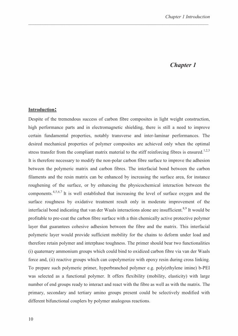
Despite of the tremendous success of carbon fibre composites in light weight construction,
high performance parts and in electromagnetic shielding, there is still a need to improve
certain fundamental properties, notably transverse and inter-laminar performances. The
desired mechanical properties of polymer composites are achieved only when the optimal
stress transfer from the compliant matrix material to the stiff reinforcing fibres is ensured.1,2,3
It is therefore necessary to modify the non-polar carbon fibre surface to improve the adhesion
between the polymeric matrix and carbon fibres. The interfacial bond between the carbon
filaments and the resin matrix can be enhanced by increasing the surface area, for instance
roughening of the surface, or by enhancing the physicochemical interaction between the
components.4,5,6,7
It is well established that increasing the level of surface oxygen and the
surface roughness by oxidative treatment result only in moderate improvement of the
interfacial bond indicating that van der Waals interactions alone are insufficient.8,9
It would be
profitable to pre-coat the carbon fibre surface with a thin chemically active protective polymer
layer that guarantees cohesive adhesion between the fibre and the matrix. This interfacial
polymeric layer would provide sufficient mobility for the chains to deform under load and
therefore retain polymer and interphase toughness. The primer should bear two functionalities
(i) quaternary ammonium groups which could bind to oxidized carbon fibre via van der Waals
force and, (ii) reactive groups which can copolymerize with epoxy resin during cross linking.
To prepare such polymeric primer, hyperbranched polymer e.g. poly(ethylene imine) b-PEI
was selected as a functional polymer. It offers flexibility (mobility, elasticity) with large
number of end groups ready to interact and react with the fibre as well as with the matrix. The
primary, secondary and tertiary amino groups present could be selectively modified with
different bifunctional couplers by polymer analogous reactions.

Chapter 1 Introduction
___________________________________________________________________________
11
Content of the thesis:
The thesis is concerned with the synthesis of functionalized cyclic carbonates,
epoxides, photoinitiators and their reaction with branched polyethylenimine. The adsorption
behaviour of these modified polymers onto highly oriented pyrolytic graphite (HOPG) is
studied by scanning force microscopy (SFM). Furthermore application of the functionalized
polymers in the field of composites and UV curable coatings has also been investigated.
Scheme 1.1 is the general scheme representing functionalization of polyethylenimine.
Chapter 1 (the present chapter) gives a short introduction of the thesis and presents the
content of this work.
In chapter 2, the state of the literature is summarized regarding the objective of this thesis
relating to bifunctional couplers, chemistry of epoxides and cyclic carbonates, structure of
polyethylenimine, carbon fibres and sizing.
Chapter 3 displays the synthesis of functional couplers based on 5-membered cyclic
carbonates and epoxides. The reactivity of cyclic carbonates and epoxides towards primary
and secondary amine are investigated. Model reactions of some of the couplers with amines
are also discussed.
Chapter 4 deals with the synthesis of Quat-Primer polymers bearing quaternary ammonium
groups and cyclic carbonate groups (2 and 5). The synthesis starts with the branched
polyethylenimine (1) as depicted in the Scheme 1.1. These modified polymers are
subsequently characterized by with respect to structure, composition and molecular weight.
Furthermore, application of these functionalized polymers in the field of carbon fibre – epoxy
resin composites is also dealt with.
Chapter 5 describes the synthesis of polymers (2) bearing long alkyl chain (C16). The
adsorption of these functionalized polymers onto HOPG in form of sub-monolayer coverage
is studied by means of SFM. Moreover, from the SFM studies the structure of functionalized
b-PEI is established.
Chapter 1 Introduction
___________________________________________________________________________
12
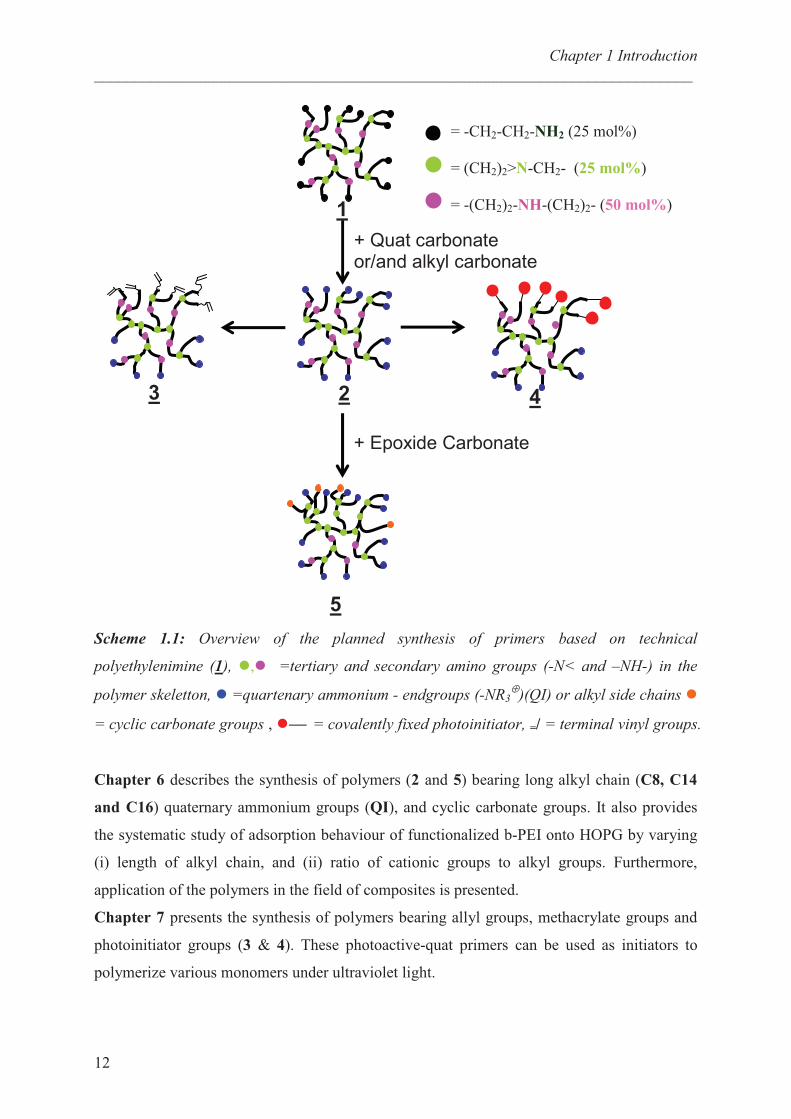
Scheme 1.1: Overview of the planned synthesis of primers based on technical
polyethylenimine (1), �,� =tertiary and secondary amino groups (-N< and –NH-) in the
polymer skeletton, � =quartenary ammonium - endgroups (-NR3⊕
)(QI) or alkyl side chains �
= cyclic carbonate groups , � = covalently fixed photoinitiator, =/ = terminal vinyl groups.
Chapter 6 describes the synthesis of polymers (2 and 5) bearing long alkyl chain (C8, C14
and C16) quaternary ammonium groups (QI), and cyclic carbonate groups. It also provides
the systematic study of adsorption behaviour of functionalized b-PEI onto HOPG by varying
(i) length of alkyl chain, and (ii) ratio of cationic groups to alkyl groups. Furthermore,
application of the polymers in the field of composites is presented.
Chapter 7 presents the synthesis of polymers bearing allyl groups, methacrylate groups and
photoinitiator groups (3 & 4). These photoactive-quat primers can be used as initiators to
polymerize various monomers under ultraviolet light.
1
3 2 4
+ Quat carbonate or/and alkyl carbonate
5
+ Epoxide Carbonate
= -CH2-CH2-NH2 (25 mol%)
= (CH2)2>N-CH2- (25 mol%)
= -(CH2)2-NH-(CH2)2- (50 mol%)
Chapter 1 Introduction
___________________________________________________________________________
13
References:
1 Drzal, L. T. Advances in Polymer Science 1986, 75, 1.
2 Zou, Y. L.; Netravali, A. N. J. Adhes. Sci. Technol. 1995, 9, 1505.
3 Yumitrori, S.; Wang, D.; Jones, F. R. Composites 1994, 25, 698.
4 Morra, M.; Ochiello, E.; Garbassi, F.; Nicolais, L. Compos. Sci. Technol. 1991, 42, 361.
5 Yuan, L. Y.; Chen, C. S.; Shyu, S. S.; Lai, J. Y. Compos. Sci. Technol. 1992, 45, 1.
6 Da, Y.; Wang, D.; Sun, M.; Chen, C.; Yue, J. Compos. Sci. Technol. 1987, 30, 119.
7 Park, S. J.; Kim, M. H. J Mater. Sci. 2000, 35, 1901.
8 Drzal, L. T.; Rich, M. J.; Lloyd, P. M. J. Adhes. 1982, 16, 1.
9 Drzal, L. T.; Rich, M. J.; Koenig, M. F.; Lloyd, P. M. J. Adhes. 1983, 16, 133.
Chapter 2 Literature Review
___________________________________________________________________________
14
Chapter 2: Literature Review
Bifunctional Couplers:
Post- synthetic modification of polymers and functionalization of various surfaces is an
important scientific topic and important for industrial applications. One of the procedures
applied to prepare multifunctional polymers is based on couplers. There are many such
examples but here only few of them will be discussed. A bifunctional coupling agent having
an oxazoline and an oxazinone groups has been reported. 1
The oxazoline groups reacts with
carboxylic acid groups whereas an oxazinone group reacts with amino or hydroxyl groups.
Thereby, different polymers such as carboxy-terminated poly(propylene) and amino
terminated polyamide have been coupled.
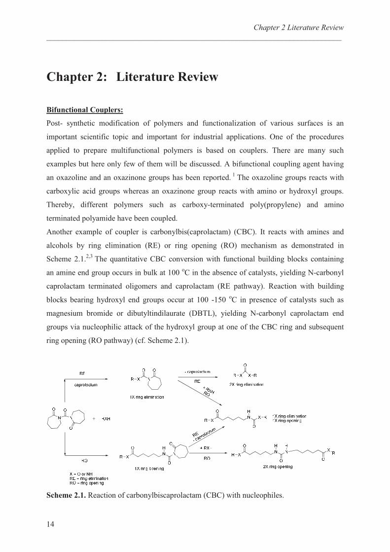
Another example of coupler is carbonylbis(caprolactam) (CBC). It reacts with amines and
alcohols by ring elimination (RE) or ring opening (RO) mechanism as demonstrated in
Scheme 2.1.2,3
The quantitative CBC conversion with functional building blocks containing
an amine end group occurs in bulk at 100 oC in the absence of catalysts, yielding N-carbonyl
caprolactam terminated oligomers and caprolactam (RE pathway). Reaction with building
blocks bearing hydroxyl end groups occur at 100 -150 oC in presence of catalysts such as
magnesium bromide or dibutyltindilaurate (DBTL), yielding N-carbonyl caprolactam end
groups via nucleophilic attack of the hydroxyl group at one of the CBC ring and subsequent
ring opening (RO pathway) (cf. Scheme 2.1).
Scheme 2.1. Reaction of carbonylbiscaprolactam (CBC) with nucleophiles.
Chapter 2 Literature Review
___________________________________________________________________________
15
Another class of couplers is based on five membered cyclic carbonates. Five membered cyclic
carbonates scarcely polymerize as a result of the stable five membered rings, whereas they
efficiently react with primary amines to afford corresponding hydroxyl urethanes.4
These couplers possess an ethylene carbonate moiety and an activated group showing
different reactivity towards primary amines. An example of this type of bifunctional coupler
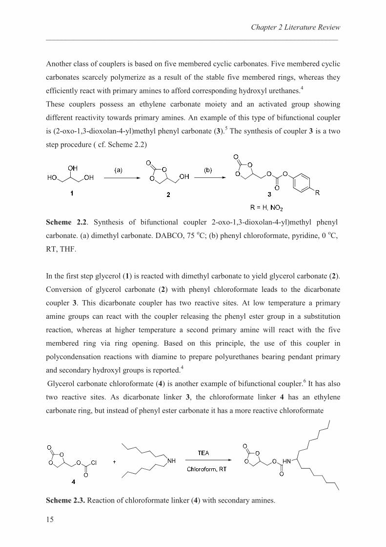
is (2-oxo-1,3-dioxolan-4-yl)methyl phenyl carbonate (3).5 The synthesis of coupler 3 is a two
step procedure ( cf. Scheme 2.2)
Scheme 2.2. Synthesis of bifunctional coupler 2-oxo-1,3-dioxolan-4-yl)methyl phenyl
carbonate. (a) dimethyl carbonate. DABCO, 75 oC; (b) phenyl chloroformate, pyridine, 0
oC,
RT, THF.
In the first step glycerol (1) is reacted with dimethyl carbonate to yield glycerol carbonate (2).
Conversion of glycerol carbonate (2) with phenyl chloroformate leads to the dicarbonate
coupler 3. This dicarbonate coupler has two reactive sites. At low temperature a primary
amine groups can react with the coupler releasing the phenyl ester group in a substitution
reaction, whereas at higher temperature a second primary amine will react with the five
membered ring via ring opening. Based on this principle, the use of this coupler in
polycondensation reactions with diamine to prepare polyurethanes bearing pendant primary
and secondary hydroxyl groups is reported.4
Glycerol carbonate chloroformate (4) is another example of bifunctional coupler.6 It has also
two reactive sites. As dicarbonate linker 3, the chloroformate linker 4 has an ethylene
carbonate ring, but instead of phenyl ester carbonate it has a more reactive chloroformate
Scheme 2.3. Reaction of chloroformate linker (4) with secondary amines.
Chapter 2 Literature Review
___________________________________________________________________________
16
groups which could react with primary amine and as well as secondary amines. The
substitution of chloroformate with an amine leads to the formation of elimination product
(HCl). To trap HCl an additional reactant like triethylamine (TEA) is required in order to
obtain full conversion (cf. Scheme 2.3).
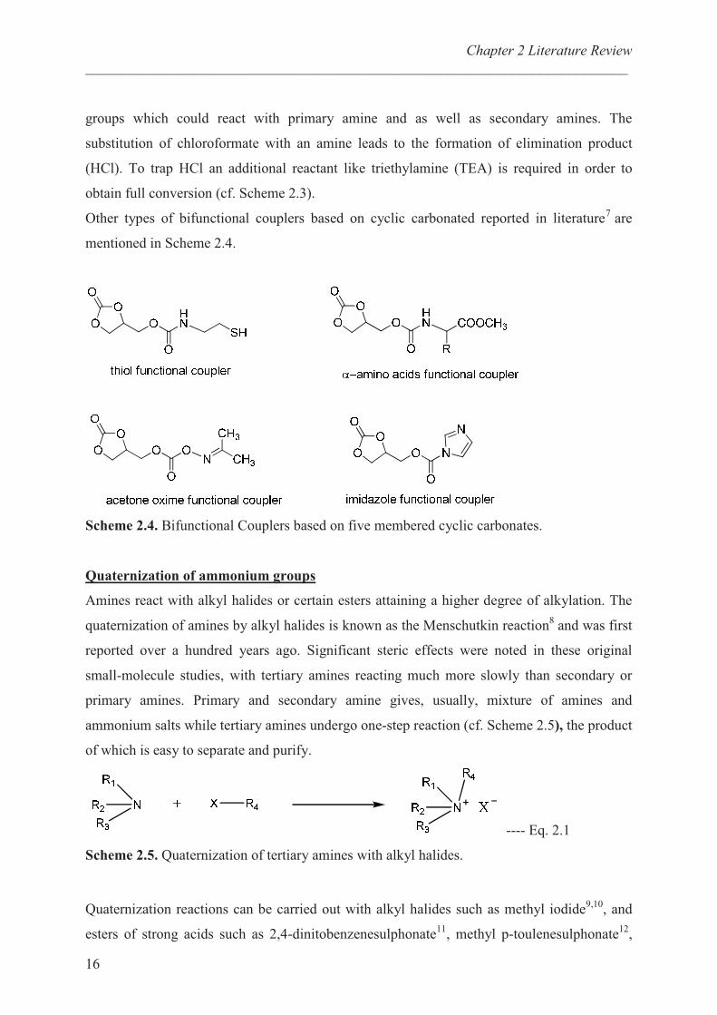
Other types of bifunctional couplers based on cyclic carbonated reported in literature7 are
mentioned in Scheme 2.4.
Scheme 2.4. Bifunctional Couplers based on five membered cyclic carbonates.
Quaternization of ammonium groups
Amines react with alkyl halides or certain esters attaining a higher degree of alkylation. The
quaternization of amines by alkyl halides is known as the Menschutkin reaction8 and was first
reported over a hundred years ago. Significant steric effects were noted in these original
small-molecule studies, with tertiary amines reacting much more slowly than secondary or
primary amines. Primary and secondary amine gives, usually, mixture of amines and
ammonium salts while tertiary amines undergo one-step reaction (cf. Scheme 2.5), the product
of which is easy to separate and purify.
---- Eq. 2.1
Scheme 2.5. Quaternization of tertiary amines with alkyl halides.
Quaternization reactions can be carried out with alkyl halides such as methyl iodide9,10
, and
esters of strong acids such as 2,4-dinitobenzenesulphonate11
, methyl p-toulenesulphonate12
,
Chapter 2 Literature Review
___________________________________________________________________________
17
methyl picrate13
, and methyl sulphate.14
The reaction can take place with or without solvent
and at a wide range of temperatures ranging from room temperature up to that of reflux. The
net effect of any such nucleophilic substitution on carbon is the gain of electron pair by the
covalent iodine atom to form iodide ion. The quaternization will run well in polar solvents.
Strong donor solvents like nitrobenzene will form weak hydrogen bonds with the alkyl groups.
This donation will be inductively transmitted to the C � I bond, making the electron pair to
shift towards iodine. This mechanism partly accounts why the reaction run over 1000 time
faster than in hexane. Quaternary ammonium salts are commonly used as disinfectants,
surfactants, fabric softeners, and as antistatic agents. These salts are most effective against
gram-positive bacteria.
Chemistry of epoxides:
An epoxide is a cyclic ether with only three ring atoms. The ethylene oxide is also called
“epoxyethane” or “oxirane”. This ring is approximately an equilateral triangle which makes it
highly strained. The strained ring makes epoxides more reactive than other cyclic ethers
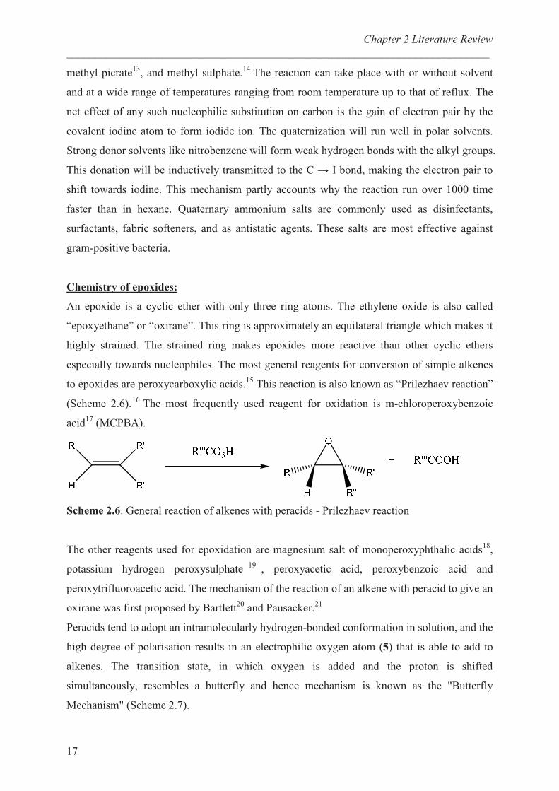
especially towards nucleophiles. The most general reagents for conversion of simple alkenes
to epoxides are peroxycarboxylic acids.15
This reaction is also known as “Prilezhaev reaction”
(Scheme 2.6).16
The most frequently used reagent for oxidation is m-chloroperoxybenzoic
acid17
(MCPBA).
Scheme 2.6. General reaction of alkenes with peracids - Prilezhaev reaction
The other reagents used for epoxidation are magnesium salt of monoperoxyphthalic acids18
,
potassium hydrogen peroxysulphate19
, peroxyacetic acid, peroxybenzoic acid and
peroxytrifluoroacetic acid. The mechanism of the reaction of an alkene with peracid to give an
oxirane was first proposed by Bartlett20
and Pausacker.21
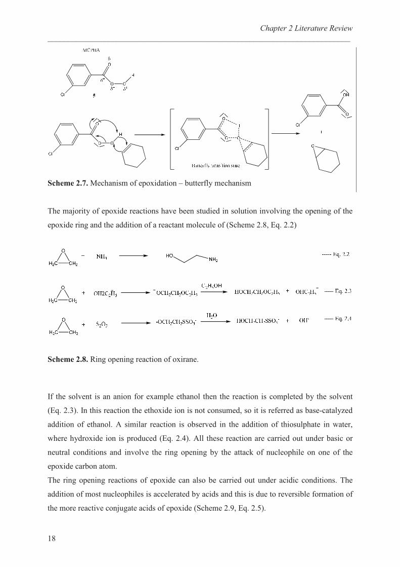
Peracids tend to adopt an intramolecularly hydrogen-bonded conformation in solution, and the
high degree of polarisation results in an electrophilic oxygen atom (5) that is able to add to
alkenes. The transition state, in which oxygen is added and the proton is shifted
simultaneously, resembles a butterfly and hence mechanism is known as the "Butterfly
Mechanism" (Scheme 2.7).
Chapter 2 Literature Review
___________________________________________________________________________
18
Scheme 2.7. Mechanism of epoxidation – butterfly mechanism
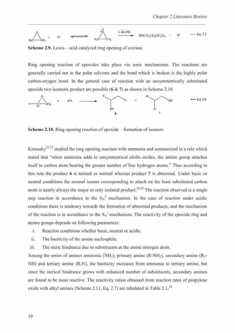
The majority of epoxide reactions have been studied in solution involving the opening of the
epoxide ring and the addition of a reactant molecule of (Scheme 2.8, Eq. 2.2)
Scheme 2.8. Ring opening reaction of oxirane.
If the solvent is an anion for example ethanol then the reaction is completed by the solvent
(Eq. 2.3). In this reaction the ethoxide ion is not consumed, so it is referred as base-catalyzed
addition of ethanol. A similar reaction is observed in the addition of thiosulphate in water,
where hydroxide ion is produced (Eq. 2.4). All these reaction are carried out under basic or
neutral conditions and involve the ring opening by the attack of nucleophile on one of the
epoxide carbon atom.
The ring opening reactions of epoxide can also be carried out under acidic conditions. The
addition of most nucleophiles is accelerated by acids and this is due to reversible formation of
the more reactive conjugate acids of epoxide (Scheme 2.9, Eq. 2.5).
Chapter 2 Literature Review
___________________________________________________________________________
19
Scheme 2.9. Lewis – acid catalyzed ring opening of oxirane.
Ring opening reaction of epoxides take place via ionic mechanisms. The reactions are
generally carried out in the polar solvents and the bond which is broken is the highly polar
carbon-oxygen bond. In the general case of reaction with an unsymmetrically substituted
epoxide two isomeric product are possible (6 & 7) as shown in Scheme 2.10.
Scheme 2.10. Ring opening reaction of epoxide – formation of isomers
Krassuky22,23
studied the ring opening reaction with ammonia and summarized in a rule which
stated that “when ammonia adds to unsymmetrical olefin oxides, the amino group attaches
itself to carbon atom bearing the greater number of free hydrogen atoms.” Thus according to
this rule the product 6 is termed as normal whereas product 7 is abnormal. Under basic or
neutral conditions the normal isomer corresponding to attack on the least substituted carbon
atom is nearly always the major or only isolated product.24,25
The reaction observed is a single
step reaction in accordance to the SN2 mechanism. In the case of reaction under acidic
conditions there is tendency towards the formation of abnormal products, and the mechanism
of the reaction is in accordance to the SN1-mechanism. The reactivity of the epoxide ring and
amino groups depends on following parameters:
i. Reaction conditions whether basic, neutral or acidic.
ii. The basiticity of the amine nucleophile.
iii. The steric hindrance due to substituents at the amine nitrogen atom.
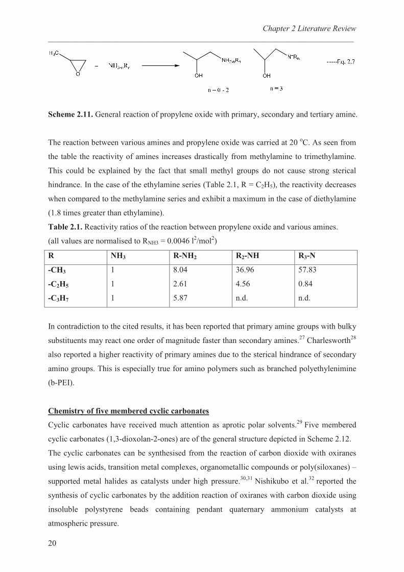
Among the series of amines ammonia (NH3), primary amine (R-NH2), secondary amine (R2-
NH) and tertiary amine (R3N), the basiticity increases from ammonia to tertiary amine, but
since the sterical hindrance grows with enhanced number of substituents, secondary amines
are found to be most reactive. The reactivity ratios obtained from reaction rates of propylene
oxide with alkyl amines (Scheme 2.11, Eq. 2.7) are tabulated in Table 2.1.26
Chapter 2 Literature Review
___________________________________________________________________________
20
Scheme 2.11. General reaction of propylene oxide with primary, secondary and tertiary amine.
The reaction between various amines and propylene oxide was carried at 20 oC. As seen from
the table the reactivity of amines increases drastically from methylamine to trimethylamine.
This could be explained by the fact that small methyl groups do not cause strong sterical
hindrance. In the case of the ethylamine series (Table 2.1, R = C2H5), the reactivity decreases
when compared to the methylamine series and exhibit a maximum in the case of diethylamine
(1.8 times greater than ethylamine).
Table 2.1. Reactivity ratios of the reaction between propylene oxide and various amines.
(all values are normalised to RNH3 = 0.0046 l2/mol
2)
R NH3 R-NH2 R2-NH R3-N
-CH3
-C2H5
-C3H7
1
1
1
8.04
2.61
5.87
36.96
4.56
n.d.
57.83
0.84
n.d.
In contradiction to the cited results, it has been reported that primary amine groups with bulky
substituents may react one order of magnitude faster than secondary amines.27
Charlesworth28
also reported a higher reactivity of primary amines due to the sterical hindrance of secondary
amino groups. This is especially true for amino polymers such as branched polyethylenimine
(b-PEI).
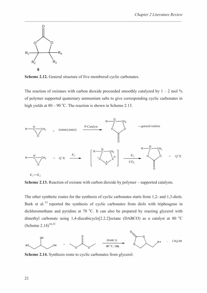
Chemistry of five membered cyclic carbonates
Cyclic carbonates have received much attention as aprotic polar solvents.29
Five membered
cyclic carbonates (1,3-dioxolan-2-ones) are of the general structure depicted in Scheme 2.12.
The cyclic carbonates can be synthesised from the reaction of carbon dioxide with oxiranes
using lewis acids, transition metal complexes, organometallic compounds or poly(siloxanes) –
supported metal halides as catalysts under high pressure.30,31
Nishikubo et al.32
reported the
synthesis of cyclic carbonates by the addition reaction of oxiranes with carbon dioxide using
insoluble polystyrene beads containing pendant quaternary ammonium catalysts at
atmospheric pressure.
Chapter 2 Literature Review
___________________________________________________________________________
21
� �
��
��
��
��
�
8
Scheme 2.12. General structure of five membered cyclic carbonates.
The reaction of oxiranes with carbon dioxide proceeded smoothly catalyzed by 1 – 2 mol %
of polymer supported quaternary ammonium salts to give corresponding cyclic carbonates in
high yields at 80 – 90 oC. The reaction is shown in Scheme 2.13.
�
������
� � � �
�����
� �
�
�
��������
�
������ � ����
�����
�
�
� ��
���
�����
� �
�
�
� ����
� ����
���������� �������
Scheme 2.13. Reaction of oxirane with carbon dioxide by polymer – supported catalysts.
The other synthetic routes for the synthesis of cyclic carbonates starts from 1,2- and 1,3-diols.
Burk et al.33
reported the synthesis of cyclic carbonates from diols with triphosgene in
dichloromethane and pyridine at 70 oC. It can also be prepared by reacting glycerol with
dimethyl carbonate using 1,4-diazabicyclo[2.2.2]octane (DABCO) as a catalyst at 80 oC
(Scheme 2.14)34,35
Scheme 2.14. Synthesis route to cyclic carbonates from glycerol.
Chapter 2 Literature Review
___________________________________________________________________________
22
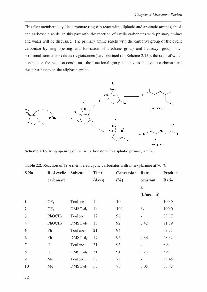
This five membered cyclic carbonate ring can react with aliphatic and aromatic amines, thiols
and carboxylic acids. In this part only the reaction of cyclic carbonates with primary amines
and water will be discussed. The primary amine reacts with the carbonyl group of the cyclic
carbonate by ring opening and formation of urethane group and hydroxyl group. Two
positional isomeric products (regioisomers) are obtained (cf. Scheme 2.15.), the ratio of which
depends on the reaction conditions, the functional group attached to the cyclic carbonate and
the substituents on the aliphatic amine.
Scheme 2.15. Ring opening of cyclic carbonate with aliphatic primary amine.
Table 2.2. Reaction of Five membered cyclic carbonates with n-hexylamine at 70 oC.
S.No R of cyclic
carbonate
Solvent Time
(days)
Conversion
(%)
Rate
constant,
k
(L/mol . h)
Product
Ratio
1
2
3
4
5
6
7
8
9
10
CF3
CF3
PhOCH2
PhOCH2
Ph
Ph
H
H
Me
Me
Toulene
DMSO-d6
Toulene
DMSO-d6
Toulene
DMSO-d6
Toulene
DMSO-d6
Toulene
DMSO-d6
1h
1h
12
17
21
17
31
31
50
50
100
100
96
92
94
92
93
91
75
75
-
64
-
0.42
-
0.38
-
0.23
-
0.05
100:0
100:0
83:17
81:19
69:31
68:32
n.d.
n.d.
55:45
55:45
Chapter 2 Literature Review
___________________________________________________________________________
23
The major product is always the isomer bearing a secondary hydroxyl group, demonstrating a
distinct regioselectivity.36
The reaction rate constant obtained from the reaction of functional
five-membered cyclic carbonates (with different substituents) with n-hexylamine are tabulated
in Table 2.2.37
As seen from the table the formation of urethanes with a secondary hydroxyl
group increased with introduction of stronger electron withdrawing group into the
corresponding cyclic carbonate. Moreover, the isomer with secondary hydroxyl group was
major product in all the cases. Pasquier et al.35
studied the model reaction of a quaternary
ammonium functional cyclic carbonate with propylamine in water. The reaction was
completed in 3 h at room temperature and the rate of reaction with propylamine was found to
be much greater than rate of hydrolysis. However, when the reaction was carried out in
methanol instead of water under the same conditions, the hydrolyzed compound was the
major product. The stability of the functional cyclic carbonate against hydrolysis was
investigated in water at room temperature and at 100 oC. It was reported that after 2 days at
room temperature only 16% of the reactant was hydrolyzed, whereas at 100 oC, 73 % of the
hydrolyzed product was obtained.
Branched Polyethylenimine (b-PEI):
The properties of the dendrimers and hyperbranched polymers are very different from the
linear polymers. By comparison to the ideally perfectly branched dendrimers, hyperbranched
polymers possess a randomly branched topology, i.e. branching is not achieved for every
monomer unit incorporated and additional linear units are present. The lack of entanglements
results in a lower viscosity, and the large extent of end functional groups cause higher
solubility in various solvents for hyperbranched polymers compared with linear structure at a
given molecular weight For example, natural polymers like glycogen, dextran and
amylopectine are hyperbranched polymers.
b-PEI is a well known polymer obtained by ring opening polymerization of aziridine,
commercially available in large ranges of molecular weights.38 , 39
The mechanism of
polymerization involves addition of proton acid to aziridine to produce the corresponding
aziridinium ion (9) (Scheme 2.16). The first propagation step is the ring opening of (9) by a
nucleophilic attack of the monomer. The formed dimer (10) can react in two ways: a new ring
opening of the aziridinium ion by monomer leads to trimer (11) while the second possibility is
that (10) transfers its proton to another amino function present in the reaction mixture thus
forming uncharged dimer N-(2-aminoethyl)-aziridine (12). The branching process occurs

Chapter 2 Literature Review
___________________________________________________________________________
24
right from the early stages of polymerization. An intramolecular reaction (back – biting
reaction) has been proposed as a termination step. In order to control the molecular weight,
the polymerization can be quenched with ethylene diamine.
�� � �� �
�
�
�
�
�
�
�
� �� �
�
���
��
���
�
��
���
��
�
���
��
�� � ��
�
�
�
���
� ��
���
�
�
��
���
���
���
��
��
��
� �
��������
�� ����
���� �������
��������� �� ��������� ���� ���� ��������������
� ��
Scheme 2.16. Mechanism of aziridine polymerization.
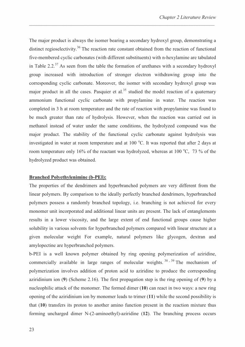
Lot of work has been put in to estimate the degree of branching in b-PEI. The difficulty to
determine structure of b-PEI is caused by its polydispersity and its chain isomerism. In 1941,
Kern and Brenneisen had already shown that benzoylation of b-PEI is incomplete and
deduced that 20 – 30 % of amino groups were tertiary. Many methods were used but the best
analytical method to study the structure is by 13
C-NMR spectroscopy.40,41
Lukovkin et al.40
observed the 13
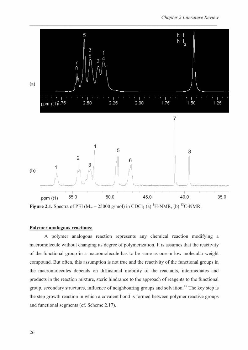
C-NMR spectrum to contain 8 lines (Figure 2.1b) which were
attributed to methylene groups having primary, secondary or tertiary amino groups in αααα� and ββββ
position. The eight major peaks have been assigned according to the different combination of
amine nearest neighbours as listed in Table 2.3. From the integration of different signals,
ratios of primary, secondary and tertiary amine groups being 31:40:29, and 31:38:31
respectively have been determined in CDCl3 solution for b-PEIs with molecular weight,
<Mw> of 25000 and 750000 g/mol.27
These results are different compared to the well
established data which were 25:50:25.38
Chapter 2 Literature Review
___________________________________________________________________________
25
Table 2.3. 13
C-NMR characterization of PEI 25000
Structral Unit in b-PEI � (ppm) Integrals
N-1CH2-CH2-NH2
N-2CH2-CH2-NH-
N-3CH2-
3CH2-N
-NH-4CH2-CH2-NH2
-NH-5CH2-
5CH2-NH-
-NH-6CH2-CH2-N
NH2-7CH2-CH2-NH-
NH2-8CH2-CH2-N
57.2
54.3
52.5
52.0
49.0
47.1
41.3
39.4
1.00
2.12
2.75
1.10
2.03
2.16
1.06
1.03
The difference can be explained due to following factors: (i) b-PEI is commercially
available polymer in large range of molecular weight while earlier it was prepared in lab scale.
(ii) The use of different catalysts, quenching agents and process parameters, and (iii) The
sensitivity of NMR instruments increased dramatically since last 30 years enabling now more
accurate measurements. Salah et. al.42
assigned methylenic signals using 1H-
1H correlation
spectroscopy and 1H-
13C hetronuclear multiple quantum correlation (HMQC). . The
1H-NMR
indicates the broad signal at 1.8 ppm and the methylenic signals overlap between 2.4 and 2.9
ppm (Figure 2.1a).
The b-PEI is soluble in water, alcohol and many polar solvents like DMF, DMSO, THF and
CHCl3. Due to its unique structure and properties b-PEI has been used in medicinal chemistry
as transfection agents43
and part of gene delivery system44
, water treatment45
, preparation of
multilayers with embedded vesicles46
, pressure sensitive adhesives, paper production,
laminated packaging films and primers for fibres.35
Chapter 2 Literature Review
___________________________________________________________________________
26
(a)
(b)
ppm (t1) 35.040.045.050.055.0
1
2
3
45
6
7
8
Figure 2.1. Spectra of PEI (Mw – 25000 g/mol) in CDCl3 (a) 1H-NMR, (b)
13C-NMR.
Polymer analogous reactions:
A polymer analogous reaction represents any chemical reaction modifying a
macromolecule without changing its degree of polymerization. It is assumes that the reactivity
of the functional group in a macromolecule has to be same as one in low molecular weight
compound. But often, this assumption is not true and the reactivity of the functional groups in
the macromolecules depends on diffusional mobility of the reactants, intermediates and
products in the reaction mixture, steric hindrance to the approach of reagents to the functional
group, secondary structures, influence of neighbouring groups and solvation.47
The key step is
the step growth reaction in which a covalent bond is formed between polymer reactive groups
and functional segments (cf. Scheme 2.17).

Chapter 2 Literature Review
___________________________________________________________________________
27
Scheme 2.17. Polymer analogous reaction – General scheme
In this study polymer analogous reaction refers to the reaction of electrophilic groups
(carboxylic acids, acid chloride, anhydrides, carbonates, epoxides, alkyl halides etc.) with the
polymer bearing nucleophilic groups (amines and alcohols). Lydie et. al. studied the reaction
of amino groups present in b-PEI with palmitic acid at 140 oC in toluene for 21 hours.
48 The
maximum degree of amidation calculated from 1H-NMR was 70%. Other amidation of b-PEI
includes reaction with palmitic acid chloride49
and methyl palmitate.50
The addition reaction
of primary amino groups in b-PEI with substituted 5-membered cyclic carbonates to yield
urethane groups and hydroxyl has also been reported.51,52,35
The functionalized polymers were
obtained in good yield (75 – 85%) and the functionalization was limited to 25 % with respect
to total amino groups in b-PEI.
Carbon Fibres
Carbon fibres are high strength, high modulus reinforcing fibres used in the manufacture of
advanced composite materials. They are black fibres used as yarns, felt or powder-like short
filaments with diameter smaller than 10 �m. These fibres are made by pyrolytic degradation
of a fibrous organic precursor. In this process, an organic polymer fibre is heated under
tension in an inert atmosphere to a very high temperature to drive off volatile constituents.
The residual carbon atoms tend to orient themselves along the fibre axis into graphitic
crystallites to form a high strength, high modulus fibres. The final properties of carbon fibre
depend on the composition of the precursor and the time – temperature history of the fibre. In
general, as the processing temperature to which the fibre is exposed is increases, the extent of
crystallite orientation parallel to fibre axis increases and hence modulus increases. Because of
greater sensitivity to flaws, the increase in modulus is generally accompanied by a decrease in
strength.
The ideal requirements of the precursor are:
� The chemical structure should favour the formation of an aligned graphitic carbon
structure during pyrolysis.
Chapter 2 Literature Review
___________________________________________________________________________
28
� A high carbon fibre yield should be obtained.
� The fibre should be strong enough to be handled during all phases of pyrolysis process.
� It should be inexpensive and readily available from various commercial sources.
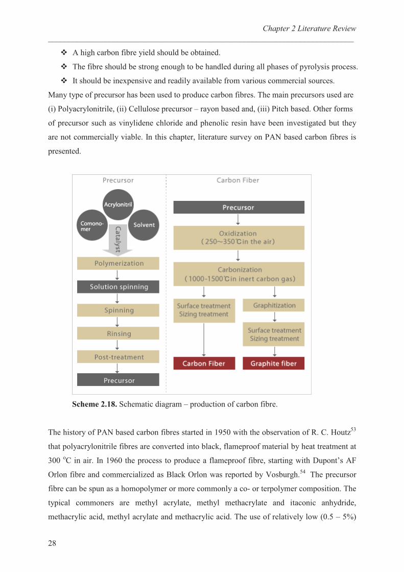
Many type of precursor has been used to produce carbon fibres. The main precursors used are
(i) Polyacrylonitrile, (ii) Cellulose precursor – rayon based and, (iii) Pitch based. Other forms
of precursor such as vinylidene chloride and phenolic resin have been investigated but they
are not commercially viable. In this chapter, literature survey on PAN based carbon fibres is
presented.
Scheme 2.18. Schematic diagram – production of carbon fibre.
The history of PAN based carbon fibres started in 1950 with the observation of R. C. Houtz53
that polyacrylonitrile fibres are converted into black, flameproof material by heat treatment at
300 oC in air. In 1960 the process to produce a flameproof fibre, starting with Dupont’s AF
Orlon fibre and commercialized as Black Orlon was reported by Vosburgh.54
The precursor
fibre can be spun as a homopolymer or more commonly a co- or terpolymer composition. The
typical commoners are methyl acrylate, methyl methacrylate and itaconic anhydride,
methacrylic acid, methyl acrylate and methacrylic acid. The use of relatively low (0.5 – 5%)
Chapter 2 Literature Review
___________________________________________________________________________
29
concentrations of comonomers, improves the dissolution and stability of polymer solution and
facilitates spinning. Polymer fibres can be spun by melt, wet and dry spinning processes. In
the case of PAN as a carbon fibre precursor, the wet spinning is the most important.
Dimethylacetamide and dimethylformamide are usually preferred solvents for wet spinning.
The fibre is highly drawn in the spinning process to align the molecular chains. The precursor
fibres are normally drawn to relatively small filament diameters of 6 – 15 �m. Contaminants
in the precursor can lead to surface defects, voids or inclusions that seriously reduce the
strength of the fibre. The process used in the production of carbon fibre is summarized in
Scheme 2.18.
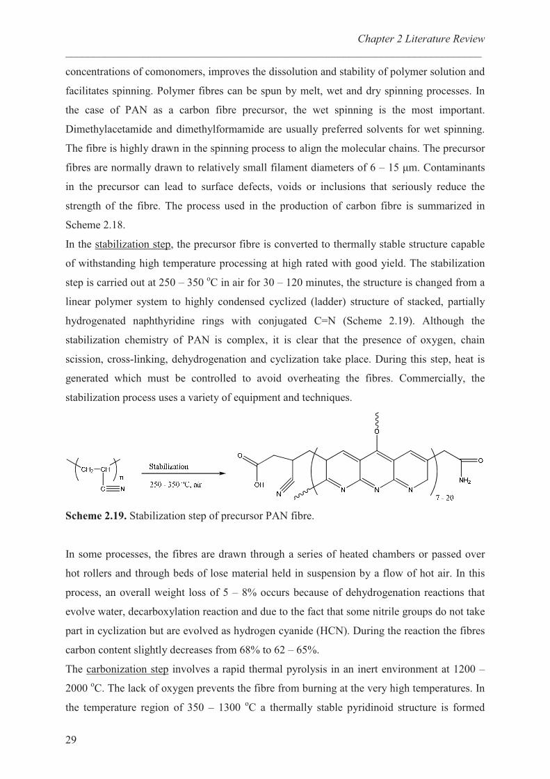
In the stabilization step, the precursor fibre is converted to thermally stable structure capable
of withstanding high temperature processing at high rated with good yield. The stabilization
step is carried out at 250 – 350 oC in air for 30 – 120 minutes, the structure is changed from a
linear polymer system to highly condensed cyclized (ladder) structure of stacked, partially
hydrogenated naphthyridine rings with conjugated C=N (Scheme 2.19). Although the
stabilization chemistry of PAN is complex, it is clear that the presence of oxygen, chain
scission, cross-linking, dehydrogenation and cyclization take place. During this step, heat is
generated which must be controlled to avoid overheating the fibres. Commercially, the
stabilization process uses a variety of equipment and techniques.
Scheme 2.19. Stabilization step of precursor PAN fibre.
In some processes, the fibres are drawn through a series of heated chambers or passed over
hot rollers and through beds of lose material held in suspension by a flow of hot air. In this
process, an overall weight loss of 5 – 8% occurs because of dehydrogenation reactions that
evolve water, decarboxylation reaction and due to the fact that some nitrile groups do not take
part in cyclization but are evolved as hydrogen cyanide (HCN). During the reaction the fibres
carbon content slightly decreases from 68% to 62 – 65%.
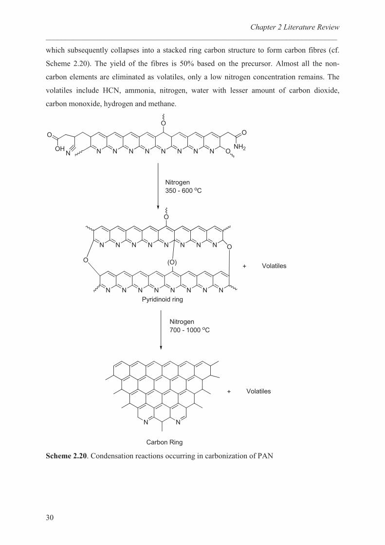
The carbonization step involves a rapid thermal pyrolysis in an inert environment at 1200 –
2000 oC. The lack of oxygen prevents the fibre from burning at the very high temperatures. In
the temperature region of 350 – 1300 oC a thermally stable pyridinoid structure is formed
Chapter 2 Literature Review
___________________________________________________________________________
30
which subsequently collapses into a stacked ring carbon structure to form carbon fibres (cf.
Scheme 2.20). The yield of the fibres is 50% based on the precursor. Almost all the non-
carbon elements are eliminated as volatiles, only a low nitrogen concentration remains. The
volatiles include HCN, ammonia, nitrogen, water with lesser amount of carbon dioxide,
carbon monoxide, hydrogen and methane.
� � ����
�
� � � � �
�
����
�
�� �����
��� � ��� ��
� � � � � � � �
�
� � � � � � � �
����
�
� ���� ����
�� �����
��� � ���� ��
� �
� ���� ����
������ ����
!��"����" ����
Scheme 2.20. Condensation reactions occurring in carbonization of PAN
Chapter 2 Literature Review
___________________________________________________________________________
31
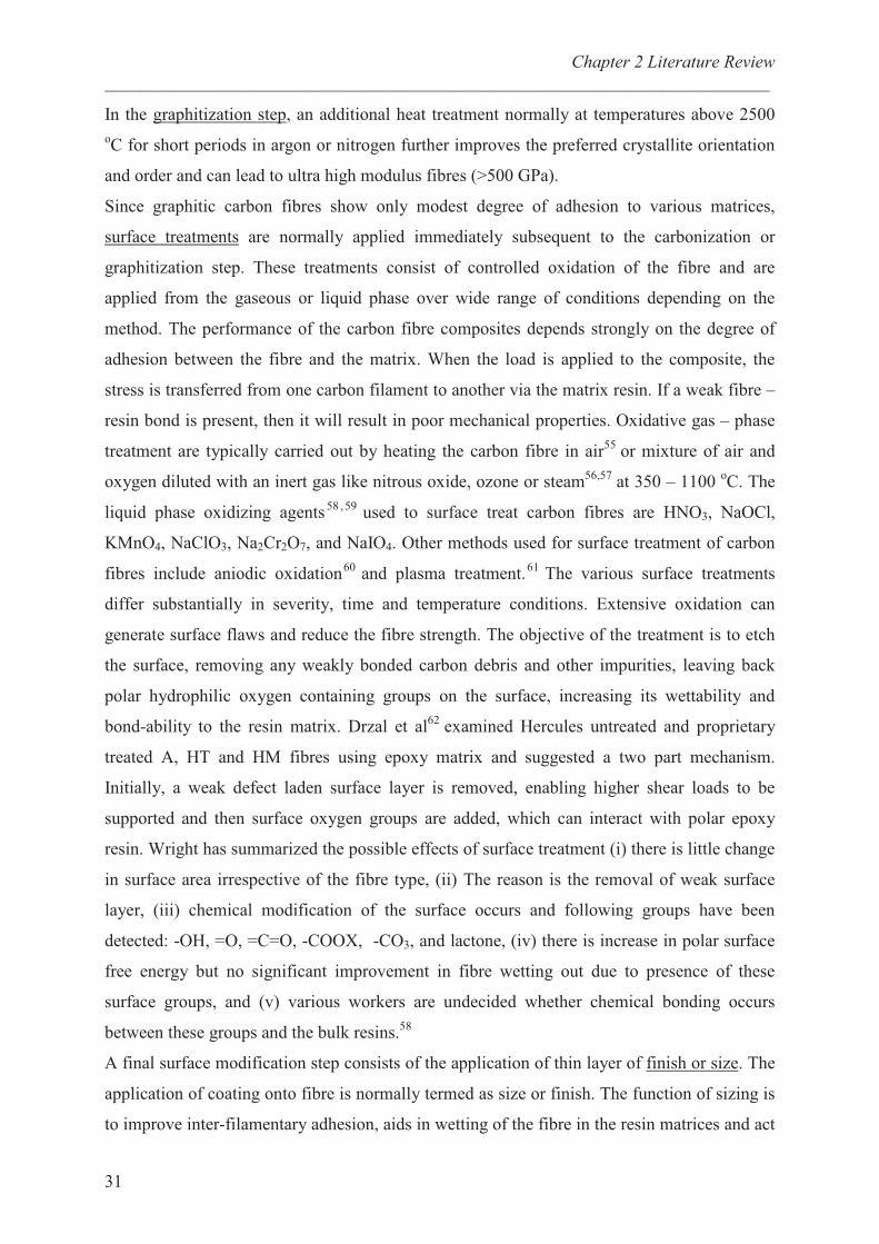
In the graphitization step, an additional heat treatment normally at temperatures above 2500
oC for short periods in argon or nitrogen further improves the preferred crystallite orientation
and order and can lead to ultra high modulus fibres (>500 GPa).
Since graphitic carbon fibres show only modest degree of adhesion to various matrices,
surface treatments are normally applied immediately subsequent to the carbonization or
graphitization step. These treatments consist of controlled oxidation of the fibre and are
applied from the gaseous or liquid phase over wide range of conditions depending on the
method. The performance of the carbon fibre composites depends strongly on the degree of
adhesion between the fibre and the matrix. When the load is applied to the composite, the
stress is transferred from one carbon filament to another via the matrix resin. If a weak fibre –
resin bond is present, then it will result in poor mechanical properties. Oxidative gas – phase
treatment are typically carried out by heating the carbon fibre in air55
or mixture of air and
oxygen diluted with an inert gas like nitrous oxide, ozone or steam56,57
at 350 – 1100 oC. The
liquid phase oxidizing agents58 ,59
used to surface treat carbon fibres are HNO3, NaOCl,
KMnO4, NaClO3, Na2Cr2O7, and NaIO4. Other methods used for surface treatment of carbon
fibres include aniodic oxidation60
and plasma treatment.61
The various surface treatments
differ substantially in severity, time and temperature conditions. Extensive oxidation can
generate surface flaws and reduce the fibre strength. The objective of the treatment is to etch
the surface, removing any weakly bonded carbon debris and other impurities, leaving back
polar hydrophilic oxygen containing groups on the surface, increasing its wettability and
bond-ability to the resin matrix. Drzal et al62
examined Hercules untreated and proprietary
treated A, HT and HM fibres using epoxy matrix and suggested a two part mechanism.
Initially, a weak defect laden surface layer is removed, enabling higher shear loads to be
supported and then surface oxygen groups are added, which can interact with polar epoxy
resin. Wright has summarized the possible effects of surface treatment (i) there is little change
in surface area irrespective of the fibre type, (ii) The reason is the removal of weak surface
layer, (iii) chemical modification of the surface occurs and following groups have been
detected: -OH, =O, =C=O, -COOX, -CO3, and lactone, (iv) there is increase in polar surface
free energy but no significant improvement in fibre wetting out due to presence of these
surface groups, and (v) various workers are undecided whether chemical bonding occurs
between these groups and the bulk resins.58
A final surface modification step consists of the application of thin layer of finish or size. The
application of coating onto fibre is normally termed as size or finish. The function of sizing is
to improve inter-filamentary adhesion, aids in wetting of the fibre in the resin matrices and act
Chapter 2 Literature Review
___________________________________________________________________________
32
as a lubricant to prevent fibre damage during subsequent textile processing. The sizing could
be achieved in different ways (i) deposition from a polymer solution, (ii) deposition of a
polymer onto fibre surface by electrodeposition, (iii) deposition of a polymer onto fibre
surface by electro-polymerization, and (iv) plasma polymerization. Among these the most
common method of sizing is the deposition from solution of polymer onto the fibre surface.
The selection of polymeric size depends on the resin matrix. Thus, sizes of epoxy resins are
generally used for epoxy matrices. To obtain the desired properties, applied sizes must not be
tacky or brittle and can be obtained by selecting an epoxy resin with suitable molecular
weight. Some workers believe that a flexible interlayer of size is preferable but other prefers a
more brittle system with modulus between that of fibre and matrix. Drzal et al63,64
termed the
vicinity of fibre and the matrix as a graded three dimensional region as interphase. The
proposed structure for the interphase is that since sizes contain no hardener, some will diffuse
from the matrix into the size layer and hence will contain less than stoichiometric amount of
curing agent. In another paper, Drzal65
studied the possible effects of this curing agent
deficiency by measuring Young’s modulus, tensile strength and fracture toughness of series of
composites. He reported that when applying less than stoichiometric amine, the system had
higher modulus, lower strength and lower toughness. Hence coating does not prevent from
fibre damage and does not improve the wetting of the fibre by matrix resin. Thus, the
resulting interphase is a more brittle material and promotes better stress transfer, resulting in
higher interfacial shear strength, but because of lower toughness, the failure mode changes
from interfacial to matrix. Jones et al66
have investigated epoxy sizes for polyethersulphone
(PES) matrix and found that when using a brominated diglycidyl ether of bisphenol-A
(DGEBA) size, the PES matrix penetrated the size and formed an interphase region, whereas
with an epoxy matrix, a strongly bound DGEBA was formed, which appeared to create an
weak interface between sizing resin and matrix.
Other method of applying size includes deposition of polymer onto fibre surface by electro
deposition. A performed polymer with an ionized group is said to be electrodeposited when,
under an applied voltage, the polymer is attracted to the oppositely charged carbon fibre in an
electrolytic cell. Subramanian et al67 , 68
used batch and continuous methods and typical
operating conditions were 10V applied for 1 min using a 2.5 % solution of polymer like
butadiene-maleic acid co-polymer, pyrrole and poly(ethylenecoacrylic acid).
Deposition by electro polymerization enables the polymerization of monomers in an
electrolytic cell, where carbon fibres can be made the anode or cathode. The solvent used to
dissolve the monomer must act as an electrolyte and be sufficiently conducting to permit a
Chapter 2 Literature Review
___________________________________________________________________________
33
uniform non-conducting layer of polymer to be applied onto the carbon fibre at a controlled
deposition rate. Harris and co-workers69
studied different systems and found best results with
o-diaminobenzene/LiClO4, yielding a 46% improvement in interfacial shear strength with
respect to an untreated fibre.
Epoxy Resins:
Epoxy resins have gained wide acceptance in protective coatings and electrical and structural
applications because of their exceptional combinations of properties such as toughness,
adhesion, chemical resistance and superior electrical properties. These resins are characterized
mainly by the presence of three – membered cyclic ethers groups commonly known as epoxy
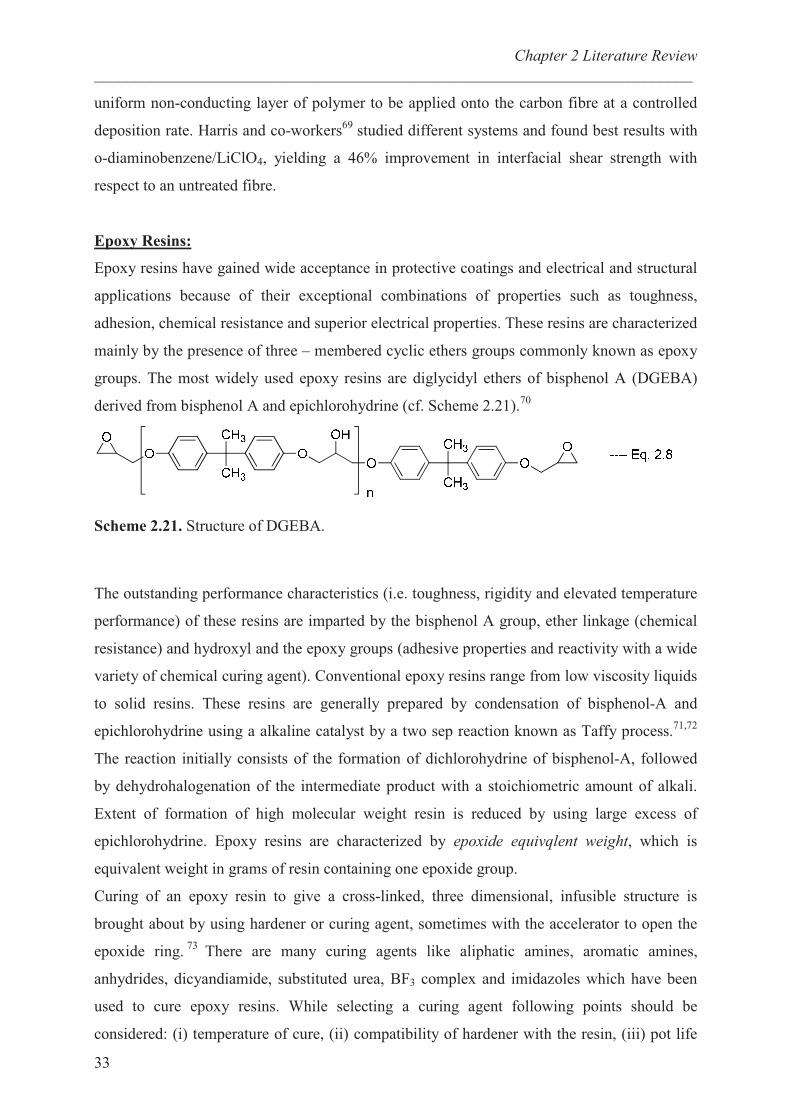
groups. The most widely used epoxy resins are diglycidyl ethers of bisphenol A (DGEBA)
derived from bisphenol A and epichlorohydrine (cf. Scheme 2.21).70
Scheme 2.21. Structure of DGEBA.
The outstanding performance characteristics (i.e. toughness, rigidity and elevated temperature
performance) of these resins are imparted by the bisphenol A group, ether linkage (chemical
resistance) and hydroxyl and the epoxy groups (adhesive properties and reactivity with a wide
variety of chemical curing agent). Conventional epoxy resins range from low viscosity liquids
to solid resins. These resins are generally prepared by condensation of bisphenol-A and
epichlorohydrine using a alkaline catalyst by a two sep reaction known as Taffy process.71,72
The reaction initially consists of the formation of dichlorohydrine of bisphenol-A, followed
by dehydrohalogenation of the intermediate product with a stoichiometric amount of alkali.
Extent of formation of high molecular weight resin is reduced by using large excess of
epichlorohydrine. Epoxy resins are characterized by epoxide equivqlent weight, which is
equivalent weight in grams of resin containing one epoxide group.
Curing of an epoxy resin to give a cross-linked, three dimensional, infusible structure is
brought about by using hardener or curing agent, sometimes with the accelerator to open the
epoxide ring.73
There are many curing agents like aliphatic amines, aromatic amines,
anhydrides, dicyandiamide, substituted urea, BF3 complex and imidazoles which have been
used to cure epoxy resins. While selecting a curing agent following points should be
considered: (i) temperature of cure, (ii) compatibility of hardener with the resin, (iii) pot life
Chapter 2 Literature Review
___________________________________________________________________________
34
of the hardener, (iv) volatility of hardener, (v) physical properties of the cured resin, and (vi)
cost. The optimum proportions of the resin and curing agent are such that the cured material
will have the highest softening temperature and the best combination of mechanical properties.
To achieve the stoichiometric amount of curing agent and the epoxy resin, it is necessary to
know the amine hydrogen equivalent weight (AHEW).
AHEW = Molecular weight of amine ---- Eq. 2.9
Number of active hydrogens
The active hydrogen corresponds to those directly bonded to the nitrogen in the curing agent.
The parts per hundred of resin (phr) of the amine is determined from:
phr of amine = AHEW . 100 ----- Eq. 2.10
Epoxide equivalent weight of resin
References:
1 Pionteck, E.; Sadhu, V. B.; Jakisch, L.; Potschke, P.; Haussler, A. Polymer 2005, 46, 6563.
2 Maier, S.; Loontjens, T.; Scholtens, B.; Mülhaupt, R. Angew. Chem. Int. Ed. 2003, 42, 5094.
3 Maier, S.; Loontjens, T.; Scholtens, B.; Mülhaupt, R. Macromolecules 2003, 36, 4727.
4 Ubaghs, L.; Fricke, N.; Keul, H.; Höcker, H. Macromol. Rapid Commun. 2004, 25, 517.
5 Pasquier, N.; Keul, H.; Moeller, M. Designed Monomers and Polymers 2005, 8, 679.
6 Pasquier, N.; Keul, H.; Heine,mE.; Moeller M.; Angelov, B.; Linser, S.; Willumeit, R.
Macromol. Biosci. 2008, 8, 903.
7 Fricke, N.; Keul, H.; Möller, M. Macromol. Chem. Phys. 2009, In print.
8 Menschutkin, N. Ber. Dtsch. Chem. Ges. 1895, 28, 1398. ( J. Chem. Soc. Abstr. 1895, 385).
9 Sharp, T. J. Chem. Soc. 1938, 1353.
10 Prasad, K. B.; Swan, G. A. J. Chem. Soc. 1958, 2024.
11 Kiprianov, A. I.; Tolmachev, A. I. Zh. Obsch. Khim. 1957, 27, 142.
12 Marvel, C. S.; Scott, E. W.; Amstutz, K. L. J. Am. Chem. Soc. 1929, 51, 3638.
13 Kohn, M.; Grauer, F. Monatsch. Chem. 1913, 34, 1751.
Chapter 2 Literature Review
___________________________________________________________________________
35
14
Sackur, O. Bull. Soc. Chim. France 1949, 270.
15 Swern, D. Organic Peroxides Vol. II Wiley-Interscience, 1971, 355.
16 March, J. Advanced Organic Chemistry, Reactions, Mechanisms and Structure, Wiley-VCH,
Weinheim, 5th
edition 2000.
17 McDonald, R. N.; Steppel, R. N.; Dorsey, J. E. Org. Synth. 1970, 50, 15.
18 Brougham, P.; Cooper, M. S.; Cummerson, D. A.; Heaney, H.; Thompson, N. Synthesis
1987, 1015.
19 Bloch, R.; Abecassis, J.; Hassan, D. J. Org. Chem. 1985, 50, 1544.
20 Bartlett, P. D. Rec. Chem. Progr. 1950, 11, 47.
21 Lynch, B. M.; Pausacker, K. H. J. Chem. Soc. 1955, 1525.
22 Krassusky, K. J. Prakt. Chem. 1907, 75, 238.
23 Krassusky, K. Compt. Rend. 1908, 146, 236.
24 Funke, A.; Benoit, G. Bull. Soc. Chim. France 1953, 1021.
25 Graham, A. R.; Millidge, A. F.; Young, D. P. J. Chem. Soc. 1954, 2180.
26 Hansson, J. Svensk Kem. Tid. 1948, 60, 183.
27 Antonietti, L.; Aymonier, C.; Schlotterbeck, U.; Garamus, V. M.; Maksimova, T.;
Richtering, W.; Mecking, S. Macromolecules 2005, 38, 5914.
28 Charlesworth, J. J. Polym. Sci., Part A: Polym. Chem. 1980, 18, 621.
29 Keul, H.; Bächer, R.; Höcker, H.; Makromol. Chem. 1986, 187, 2579.
30 De Pasaquale, R. J. J. Chem. Soc. 1973, 157.
31 Koinuma, H.; Kato, H.; Hirai, H. Chem. Lett. 1977, 517.
32 Nishikubo, T.; Kameyama, A.; Yamashita, J.; Tomoi, M.; Fukuda, W. J. Polym. Sci., Part
A 1993, 31, 939.
33 Burk, R. M.; Roof, M. B. Tetrahedron Lett. 1993, 34, 395.
34 Jansen, J. F. G. A.; Dias, A. A.; Dorschu, M.; Coussens, B. Macromolecules 2003, 36, 3861.
Chapter 2 Literature Review
___________________________________________________________________________
36
35
Pasquier, N.; Keul, H.; Moeller, M. Designed Monomers and Polymers 2005, 8, 679.
36 Webster, D. C. Polym.News 1998, 23, 187.
37 Tomita, H.; Sanda, F.; Endo, T. J. Polym. Sci., Part A 2001, 39, 3678.
38 Kobayashi, S. Progress in Polymer Science 1990, 15, 751.
39 Dick, C. R.; Ham, G. E. J. Macromol. Sci., Chemistry 1970, 4, 1301.
40 Lukovkin, G. L.; Pshezhetsky, V. S.; Murtazaeva, G. A. Eur. Polym. J. 1973, 9, 559.
41 Pierre, T. S.; Geckle, M. Polym. Prepr. Am. Chem. Soc., Div, Polym. Chem. 1981, 22, 128.
42 Idris, S. A.; Mkhatresh, O. A.; Heatley, F. Poly. Int. 2006, 55, 1040.
43 Steele, T. W. J.; Shier, W. T. Polym. Prepr. 2004, 45, 809.
44 Forrest, M. L.; Meister, G. E.; Koerber, J. T., Pack, D. W. Pharm. Res. 2004, 21, 365.
45 Kryvoruchko, A. P.; Yurlova, L. Yu.; Atamanenko, I. D.; Kornilovich, B. Yu. Desalination
2004, 162, 229.
46 Michel, M.; Vautier, D.; Voegel, J. C.; Schaaf, P.; Ball, V. Langmuir 2004, 20, 4835.
47 Odian, G. Principle of polymerization, 4
th edition pp. 729.
48 Tuchbreiter, L. Thesis “Hybrids of metal nanoparticles and amphiphilic hyperbranched
polyethylenimine used as soluble separable catalysts” 2006.
49 Haag, R.; Krämer, M.; Stumbé, J. F.; Krause, Komp, A.; Prokhorova, S. Polym. Prepr.
2002, 43, 328.
50 Dimitrova, P.; Hasana, E.; Rangelova, S.; Trzebickab, B.; Dworakb, A.; Tsvetanova, C. B.
Polymer 2002, 43, 7171.
51 Moeller, M.; Beginn, U.; Keul, H.; Thomas, H. European Patent 2006, EP 1710282 A1
2006 1011.
52 Pasquier, N.; Keul, H.; Heine, E.; Moeller, M. Biomacromolecules 2007, 8, 2874.
53 Houtz, R. Z. Tex. Res. J. 1950, 20, 786.
54 Vosburgh, W. G. Tex. Res. J. 1960, 30, 882.
Chapter 2 Literature Review
___________________________________________________________________________
37
55
Herrick, J. W.; Gruber, P. E.; Mansur, F. T. “Surface Treatments for fibrous Carbon
Reinforcements”AFML-TR-66-178 Part I 1996.
56 Ryu, S. R.; Jin, H.; Gondy, D.; Pusset, N.; Ehrburger, P. Carbon 1993, 31, 841.
57 Alcaniz, J.; Cazorla, D.; Linares, A.; Yoshida, S.; Oya, A. Carbon 1994, 32, 1277.
58 Wright, W. W. Polymer and Polym. Comp. 1990, 3, 231.
59 Goan, J. C.; Joo, L. A. Sharpe, G. E. “Surface Treatment of Graphite Fibres” 27
thAnn. Tech.
Conf. Reinf. Plast./Comp Inst 1972, 27, 1.
60 Weinberg, N. L.; Reddy, T. B. J. Appl Electrochem. 1973, 3, 73.
61 Jones, C.; Sammann, E. Carbon 1990, 28, 509.
62 Drzal, L. T.; Rich, M. J.; Lloyd, P. F. J. Adhesion 1982, 16, 1.
63 Drzal, L. T. Vacuum 1990, 41, 1615.
64 Drzal, L. T. Mater. Sci. Eng. 1990, A126, 289.
65 Drzal, L. T.; Rich, M. J.; Lloyd, P. F. J. Adhesion 1983, 16, 133.
66 Yumitori, S.; Wang, D.; Jones, F. R. Composites 1994, 25, 698.
67 Crasto, A. S.; Owa, S. H.; Subramanian, R. V. Polym. Composites 1988, 9, 78.
68 Crasto, A. S.; Owa, S. H.; Subramanian, R. V. Composite Interfaces 1986, 133.
69 Harris, B.; Braddell, O. G.; Lefebvre, C.; Verbist, J. Plastics Rubber and Composites
Processing and Applications 1992, 18, 221.
70 Batzer, H.; Zahir, S. A. J. Appl. Polym. Sci. 1975, 19,601.
71 Fisch, W. Chimin, 1962, 16, 66.
72 Batzer, H.; Zahir, S. A. J. Appl. Polym. Sci. 1977, 21,1843.
73 Buggy, M.; Temimhan, T.; Braddell, O. J. Mater. Process. Technol 1996, 56, 292.
Chapter 3
___________________________________________________________________________
38
Chapter 3: Synthesis and Characterization of
functional couplers.
Introduction:
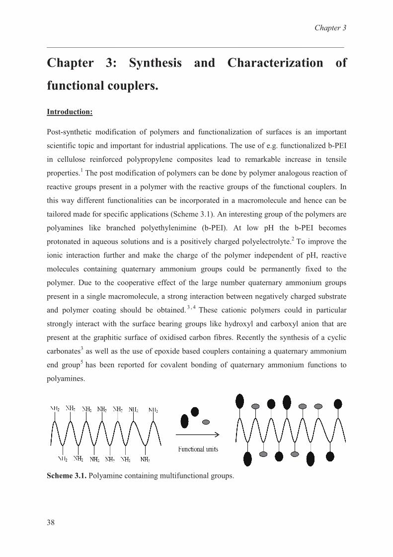
Post-synthetic modification of polymers and functionalization of surfaces is an important
scientific topic and important for industrial applications. The use of e.g. functionalized b-PEI
in cellulose reinforced polypropylene composites lead to remarkable increase in tensile
properties.1 The post modification of polymers can be done by polymer analogous reaction of
reactive groups present in a polymer with the reactive groups of the functional couplers. In
this way different functionalities can be incorporated in a macromolecule and hence can be
tailored made for specific applications (Scheme 3.1). An interesting group of the polymers are
polyamines like branched polyethylenimine (b-PEI). At low pH the b-PEI becomes
protonated in aqueous solutions and is a positively charged polyelectrolyte.2 To improve the
ionic interaction further and make the charge of the polymer independent of pH, reactive
molecules containing quaternary ammonium groups could be permanently fixed to the
polymer. Due to the cooperative effect of the large number quaternary ammonium groups
present in a single macromolecule, a strong interaction between negatively charged substrate
and polymer coating should be obtained.3 , 4
These cationic polymers could in particular
strongly interact with the surface bearing groups like hydroxyl and carboxyl anion that are
present at the graphitic surface of oxidised carbon fibres. Recently the synthesis of a cyclic
carbonates3 as well as the use of epoxide based couplers containing a quaternary ammonium
end group5 has been reported for covalent bonding of quaternary ammonium functions to
polyamines.
Scheme 3.1. Polyamine containing multifunctional groups.
Chapter 3
___________________________________________________________________________
39
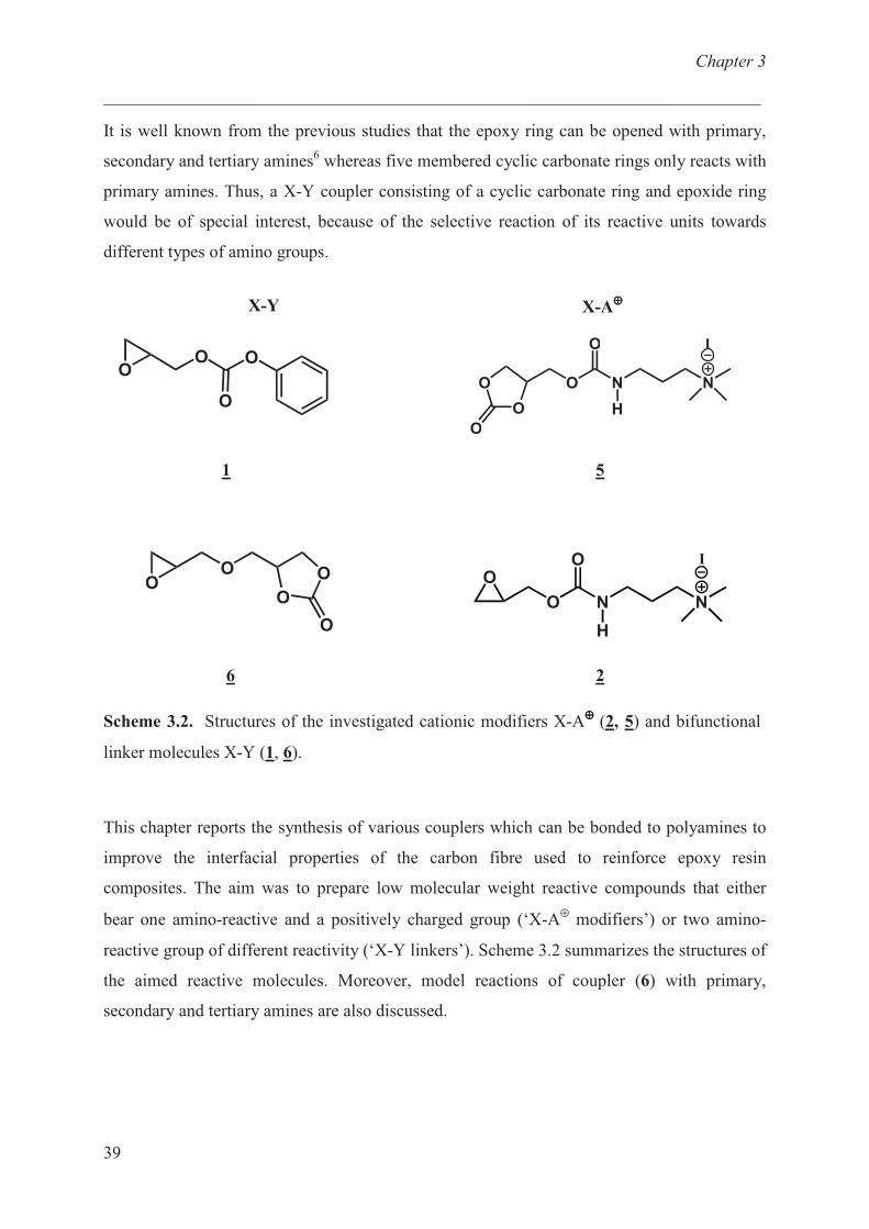
It is well known from the previous studies that the epoxy ring can be opened with primary,
secondary and tertiary amines6 whereas five membered cyclic carbonate rings only reacts with
primary amines. Thus, a X-Y coupler consisting of a cyclic carbonate ring and epoxide ring
would be of special interest, because of the selective reaction of its reactive units towards
different types of amino groups.
X-Y X-A⊕⊕⊕⊕
OO O
OO N N
I
H
O
O
O
O
1 5
OO
O
O
O
� � �
�
�
�
�
6 2
Scheme 3.2. Structures of the investigated cationic modifiers X-A⊕⊕⊕⊕ (2, 5) and bifunctional
linker molecules X-Y (1, 6).
This chapter reports the synthesis of various couplers which can be bonded to polyamines to
improve the interfacial properties of the carbon fibre used to reinforce epoxy resin
composites. The aim was to prepare low molecular weight reactive compounds that either
bear one amino-reactive and a positively charged group (‘X-A⊕
modifiers’) or two amino-
reactive group of different reactivity (‘X-Y linkers’). Scheme 3.2 summarizes the structures of
the aimed reactive molecules. Moreover, model reactions of coupler (6) with primary,
secondary and tertiary amines are also discussed.
Chapter 3
___________________________________________________________________________
40
Materials and Methods
Materials
Glycidol (Acros, 96%), phenyl chloroformate (Acros, 99% ), pyridine (Aldrich, 99.8%),
allyl alcohol (Aldrich, 99+%), 1,4-diazabicyclo[2.2.2]octane (DABCO, Aldrich, 98%), allyl
amine (Aldrich, 98%), 3-chloroperoxybenzoic acid (Acros, 70-75%, MCPBA), N,N-
dimethylpropane-1,3-diamine (Aldrich, 99%), iodomethane (Acros, 99%), epichlorohydrine
(Aldrich, 99%), 4-(hydroxymethyl)-1,3-dioxolan-2-one (Aldrich) were used as received. All
solvents were distilled before using.
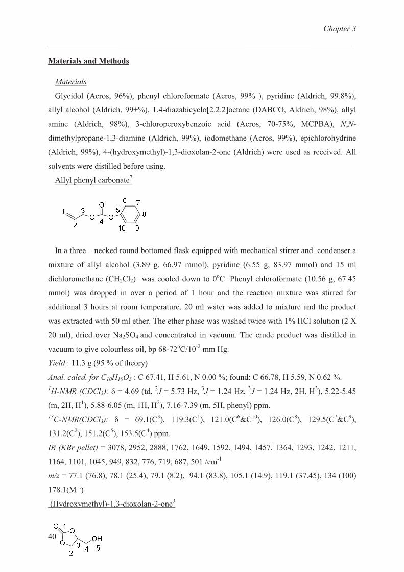
Allyl phenyl carbonate7
In a three – necked round bottomed flask equipped with mechanical stirrer and condenser a
mixture of allyl alcohol (3.89 g, 66.97 mmol), pyridine (6.55 g, 83.97 mmol) and 15 ml
dichloromethane (CH2Cl2) was cooled down to 0oC. Phenyl chloroformate (10.56 g, 67.45
mmol) was dropped in over a period of 1 hour and the reaction mixture was stirred for
additional 3 hours at room temperature. 20 ml water was added to mixture and the product
was extracted with 50 ml ether. The ether phase was washed twice with 1% HCl solution (2 X
20 ml), dried over Na2SO4 and concentrated in vacuum. The crude product was distilled in
vacuum to give colourless oil, bp 68-72oC/10
-2 mm Hg.
Yield : 11.3 g (95 % of theory)
Anal. calcd. for C10H10O3 : C 67.41, H 5.61, N 0.00 %; found: C 66.78, H 5.59, N 0.62 %.
1H-NMR (CDCl3): � = 4.69 (td,
2J = 5.73 Hz,
3J = 1.24 Hz,
3J = 1.24 Hz, 2H, H
3), 5.22-5.45
(m, 2H, H1), 5.88-6.05 (m, 1H, H
2), 7.16-7.39 (m, 5H, phenyl) ppm.
13C-NMR(CDCl3): � = 69.1(C
3), 119.3(C
1), 121.0(C
6&C
10), 126.0(C
8), 129.5(C
7&C
9),
131.2(C2), 151.2(C
5), 153.5(C
4) ppm.
IR (KBr pellet) = 3078, 2952, 2888, 1762, 1649, 1592, 1494, 1457, 1364, 1293, 1242, 1211,
1164, 1101, 1045, 949, 832, 776, 719, 687, 501 /cm-1
m/z = 77.1 (76.8), 78.1 (25.4), 79.1 (8.2), 94.1 (83.8), 105.1 (14.9), 119.1 (37.45), 134 (100)
178.1(M+.
)
(Hydroxymethyl)-1,3-dioxolan-2-one3
Chapter 3
___________________________________________________________________________
41
Glycerol (25.0 g, 271 mmol), dimethyl carbonate (DMC) (72.76g, 813 mmol) and DABCO
(291 mg, 2.71 mmol) were mixed and heated at 75°C for 10 h. After distillation of MeOH and
excess DMC under vacuum, glycerol carbonate was used without further purification for the
synthesis of the dicarbonate.
Yield : 24.96 g (78 % of theoretical)
Anal. calcd. for C4H6O4 : C 40.68, H 5.12, N 0.00 %; found: C 40.75, H 5.59, N 0.00 %.
1H-NMR(DMSO-d6): � = 3.51 (ddd,
2J = 12.7 Hz,
3J = 5.6 Hz,
3J = 3.3 Hz, 1H, H
4), 3.67 (ddd,
2J = 12.7 Hz,
3J = 5.4 Hz,
3J = 2.8 Hz, 1H, H
4), 4.29 (dd,
2J = 8.2 Hz,
3J = 5.8 Hz, 1H, H
2),
4.50 (dd, 2J �
3J � 8.3 Hz, 1H, H
2), 4.80 (dddd,
3J = 8.6 Hz,
3J = 5.8 Hz,
3J �
3J = 3.0 Hz, 1H,
H3), 5.26 (dd,
3J �
3J � 5.4-5.6 Hz, 1H, OH) ppm.
13C-NMR (DMSOd6): δ = 60.6 (C
4), 65.8 (C
2), 77.0 (C
3), 155.2 (C
1) ppm.
IR (KBr pellet) = 3404, 2929, 2881, 1786, 1552, 1481, 1402, 1338, 1279, 1178, 1085, 1053,
983, 943, 856, 775, 716, 576 / cm-1
m/z = 77.1 (5.1), 87.1 (100), 90.1 (6.4), 94.1 (83.8), 119.1(M+.
)
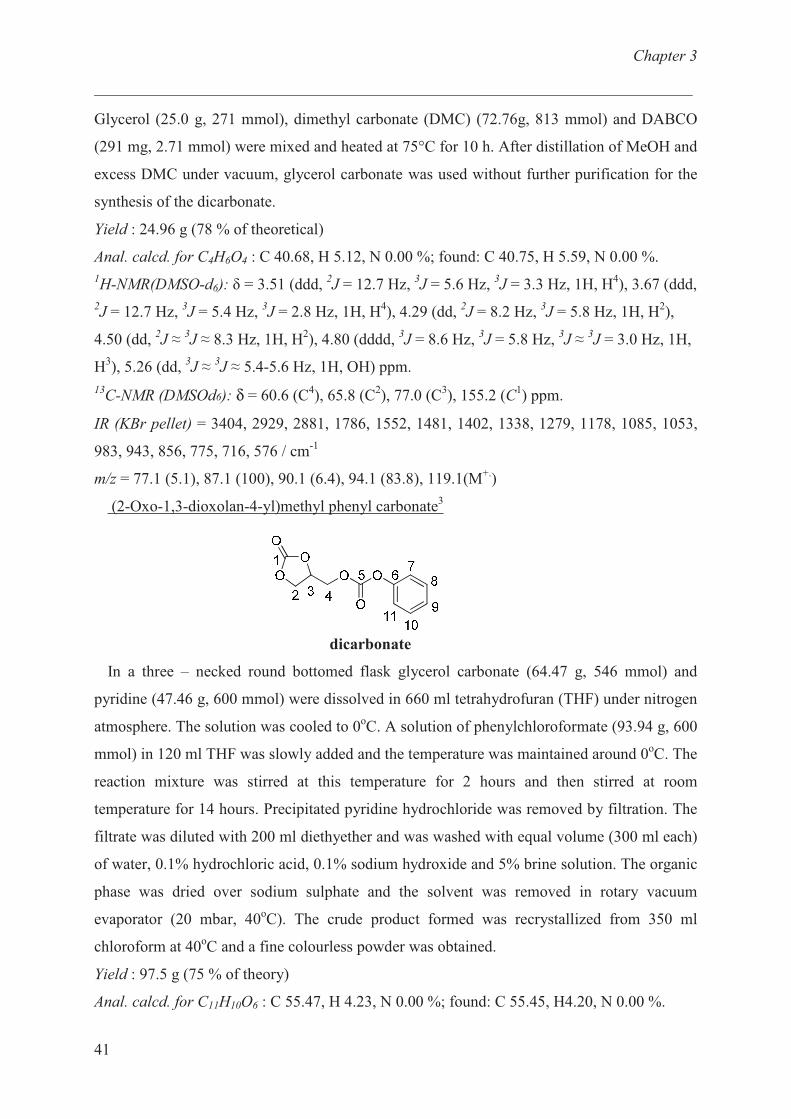
(2-Oxo-1,3-dioxolan-4-yl)methyl phenyl carbonate3
dicarbonate
In a three – necked round bottomed flask glycerol carbonate (64.47 g, 546 mmol) and
pyridine (47.46 g, 600 mmol) were dissolved in 660 ml tetrahydrofuran (THF) under nitrogen
atmosphere. The solution was cooled to 0oC. A solution of phenylchloroformate (93.94 g, 600
mmol) in 120 ml THF was slowly added and the temperature was maintained around 0oC. The
reaction mixture was stirred at this temperature for 2 hours and then stirred at room
temperature for 14 hours. Precipitated pyridine hydrochloride was removed by filtration. The
filtrate was diluted with 200 ml diethyether and was washed with equal volume (300 ml each)
of water, 0.1% hydrochloric acid, 0.1% sodium hydroxide and 5% brine solution. The organic
phase was dried over sodium sulphate and the solvent was removed in rotary vacuum
evaporator (20 mbar, 40oC). The crude product formed was recrystallized from 350 ml
chloroform at 40oC and a fine colourless powder was obtained.
Yield : 97.5 g (75 % of theory)
Anal. calcd. for C11H10O6 : C 55.47, H 4.23, N 0.00 %; found: C 55.45, H4.20, N 0.00 %.

Chapter 3
___________________________________________________________________________
42
1H NMR (DMSO-d6): � = 4.39 (dd,
2J = 8.7 Hz,
3J= 6.0 Hz, 1H, H
2), 4.46 (dd,
2J = 12.4 Hz,
3J = 4.9 Hz 1H, H
4), 4.53 (dd,
2J = 12.4 Hz,
3J =2.6 Hz, 1H, H
4), 4.62 (dd,
2J = 8.7 Hz,
3J =
8.7 Hz, 1H, H2), 5.11-5.18 (m, 1H, H
3), 7.25-7.45 (m, 5H, phenyl) ppm.
13C NMR (DMSO-d6): � = 65.7 (C
2), 67.5 (C
4), 74.0 (C
3), 121.2 (2C, C
7), 126.3 (C
9), 129.6
(2C, C8), 150.6 (C
6), 152.7 (C
5), 154.6 (C
1) ppm.
IR (KBr pellet) = 1798, 1762, 1749, 1592, 1496, 1457, 1396, 1319, 1285, 1265, 1217, 1194,
1169, 1097, 1082, 1022, 770, 717, 690, 505. /cm-1
m/z = 77.1 (66), 87.1 (12.6), 90.1 (30), 94.1 (100), 107.1 (10.9), 121.1 (4.9), 141.1 (7.6),
169.1 (3.4), 194.1 (2.4), 214.1 (9.2), 238.1(M+.
)
Oxiran-2-ylmethyl phenyl carbonate (1)
1
A) Allyl phenyl carbonate (2.6 g, 14.59 mmol) and 3-chloroperoxybenzoic acid (6.29 g,
36.46 mmol) (MCPBA) were dissolved in 30 ml dichloromethane (CH2Cl2) and the solution
was stirred for 48 hours at room temperature. The precipitated m-chlorobenzoic acid was
filtered off and the filtrate was diluted with 20 ml dichloromethane. 6 g of potassium
carbonate was added to the organic phase and stirred for 15 minutes. The salt was removed by
filtration and the filtrate was concentrated in a rotary vacuum evaporator at 500 mbar, 40oC.
The distillation (0.1 mbar, 95 o
C) of the crude product resulted in the desired product.
Yield: 2.0 g (71% of theory).
Anal. calcd. for C10H10O4 : C 61.85, H 5.28, N 0.00 %; found: C 62.15, H 5.28, N 0.64 %.
1H-NMR (CDCl3): � = 2.70 (td,
2J = 13.27 Hz,
3J = 6.64 Hz,
3J = 6.64 Hz, 1H, H
1), 2.90(t,
1H, H1), 3.25- 3.31(m, 1H, H
2), 4.10(dd,
2J = 12.08 Hz,
3J = 6.17 Hz, 1H, H
3), 4.51 (dd,
2J =
12.08 Hz, 3J = 3.08 Hz, 1H, H
3), 7.16-7.39 (m, 5H, phenyl) ppm.
13C-NMR(CDCl3): � = 44.5(C
1), 48.9(C
2), 68.9(C
3), 121.1(2C, C
6 & C
9), 126.2(C
8),
129.5(2C, C7 & C
10), 151.0(C
5), 153.5(C
4) ppm.
m/z = 77.1 (39.8), 94 (100), 107 (15.8), 120 (2.9), 194.1(M+.
).
IR (KBr pellet) = 3063, 3005, 2957, 2296, 2038, 1950, 1765, 1592, 1487, 1456, 1387, 1348,
1244, 1211, 1164, 1057, 1023, 989, 947, 914, 865, 833, 775, 713, 688, 613, 565, 505 /cm-1
B) In a three – necked round bottomed flask glycidol (5 g, 67.50 mmol), and pyridine
(5.886 g, 74.25 mmol) were dissolved in 70 ml tetrahydrofuran (THF) under nitrogen
Chapter 3
___________________________________________________________________________
43
atmosphere. The solution was cooled to 0oC. A solution of phenyl chloroformate (11.62 g,
74.25 mmol) in 15 ml THF was slowly added and the temperature was maintained around
0oC. The contents were stirred at this temperature for 2 hours and then stirred at room
temperature for 14 hours and pyridine hydrochloride formed was removed by vacuum
filtration. The filtrate was diluted with 10 ml diethylether and was washed with equal volumes
(5 ml) of water, 0.1% hydrochloric acid, 0.1% sodium hydroxide and brine solution. The
organic phase was dried over sodium sulphate and the solvent was removed in rotary vacuum
evaporator (20 mbar, 40oC). The product was purified by column chromatography on silica
gel (Ø – 2cm, column length – 50cm) (ethyl acetate/n-hexane, 2:4) to afford a colourless
liquid.
Yield: 3.90 g (30% of theory).
Characterization same as Method A.
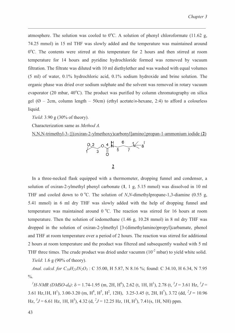
N,N,N-trimethyl-3-{[(oxiran-2-ylmethoxy)carbonyl]amino}propan-1-ammonium iodide (2)
2
In a three-necked flask equipped with a thermometer, dropping funnel and condenser, a
solution of oxiran-2-ylmethyl phenyl carbonate (1, 1 g, 5.15 mmol) was dissolved in 10 ml
THF and cooled down to 0 o
C. The solution of N,N-dimethylpropane-1,3-diamine (0.55 g,
5.41 mmol) in 6 ml dry THF was slowly added with the help of dropping funnel and
temperature was maintained around 0 o
C. The reaction was stirred for 16 hours at room
temperature. Then the solution of iodomethane (1.46 g, 10.28 mmol) in 8 ml dry THF was
dropped in the solution of oxiran-2-ylmethyl [3-(dimethylamino)propyl]carbamate, phenol
and THF at room temperature over a period of 2 hours. The reaction was stirred for additional
2 hours at room temperature and the product was filtered and subsequently washed with 5 ml
THF three times. The crude product was dried under vacumm (10-2
mbar) to yield white solid.
Yield: 1.6 g (90% of theory).
Anal. calcd. for C10H21IN2O3 : C 35.00, H 5.87, N 8.16 %; found: C 34.10, H 6.34, N 7.95
%.
1H-NMR (DMSO-d6): � = 1.74-1.95 (m, 2H, H
6), 2.62 (t, 1H, H
1), 2.78 (t,
3J = 3.61 Hz,
3J =
3.61 Hz,1H, H1), 3.00-3.20 (m, H
8, H
5, H
2, 12H), 3.25-3.45 (t, 2H, H
7), 3.72 (dd,
2J = 10.96
Hz, 3J = 6.61 Hz, 1H, H
3), 4.32 (d,
2J = 12.25 Hz, 1H, H
3), 7.41(s, 1H, NH) ppm.
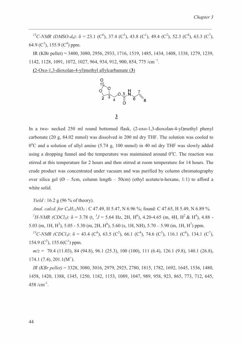
Chapter 3
___________________________________________________________________________
44
13C-NMR (DMSO-d6): � = 23.1 (C
6), 37.4 (C
5), 43.8 (C
1), 49.4 (C
2), 52.3 (C
8), 63.3 (C
7),
64.9 (C3), 155.9 (C
4) ppm.
IR (KBr pellet) = 3400, 3080, 2956, 2933, 1716, 1519, 1485, 1434, 1408, 1338, 1279, 1239,
1142, 1128, 1091, 1072, 1027, 964, 934, 912, 900, 854, 775 /cm−1
.
(2-Oxo-1,3-dioxolan-4-yl)methyl allylcarbamate (3)
3
In a two- necked 250 ml round bottomed flask, (2-oxo-1,3-dioxolan-4-yl)methyl phenyl
carbonate (20 g, 84.02 mmol) was dissolved in 200 ml dry THF. The solution was cooled to
0oC and a solution of allyl amine (5.74 g, 100 mmol) in 40 ml dry THF was slowly added
using a dropping funnel and the temperature was maintained around 0oC. The reaction was
stirred at this temperature for 2 hours and then stirred at room temperature for 14 hours. The
crude product was concentrated under vacuum and was purified by column chromatography
over silica gel (Ø – 5cm, column length – 50cm) (ethyl acetate/n-hexane, 1:1) to afford a
white solid.
Yield : 16.2 g (96 % of theory).
Anal. calcd. for C8H11NO5 : C 47.49, H 5.47, N 6.96 %; found: C 47.65, H 5.49, N 6.89 %.
1H-NMR (CDCl3): � = 3.78 (t,
3J = 5.64 Hz, 2H, H
6), 4.20-4.65 (m, 4H, H
2 & H
4), 4.88 -
5.03 (m, 1H, H3), 5.05 - 5.30 (m, 2H, H
8), 5.60 (s, 1H, NH), 5.70 – 5.90 (m, 1H, H
7) ppm.
13C-NMR (CDCl3): � = 43.4 (C
6), 63.5 (C
2), 66.1 (C
4), 74.6 (C
3), 116.1 (C
8), 134.1 (C
7),
154.9 (C5), 155.6(C
1) ppm.
m/z = 70.4 (11.03), 84 (94.8), 96.1 (25.3), 100 (100), 111 (6.4), 126.1 (9.8), 140.1 (26.8),
174.1 (7.4), 201.1(M+).
IR (KBr pellet) = 3328, 3080, 3016, 2979, 2925, 2780, 1815, 1782, 1692, 1645, 1536, 1480,
1458, 1420, 1388, 1345, 1250, 1182, 1153, 1089, 1047, 989, 958, 923, 865, 773, 712, 645,
458 /cm-1
.
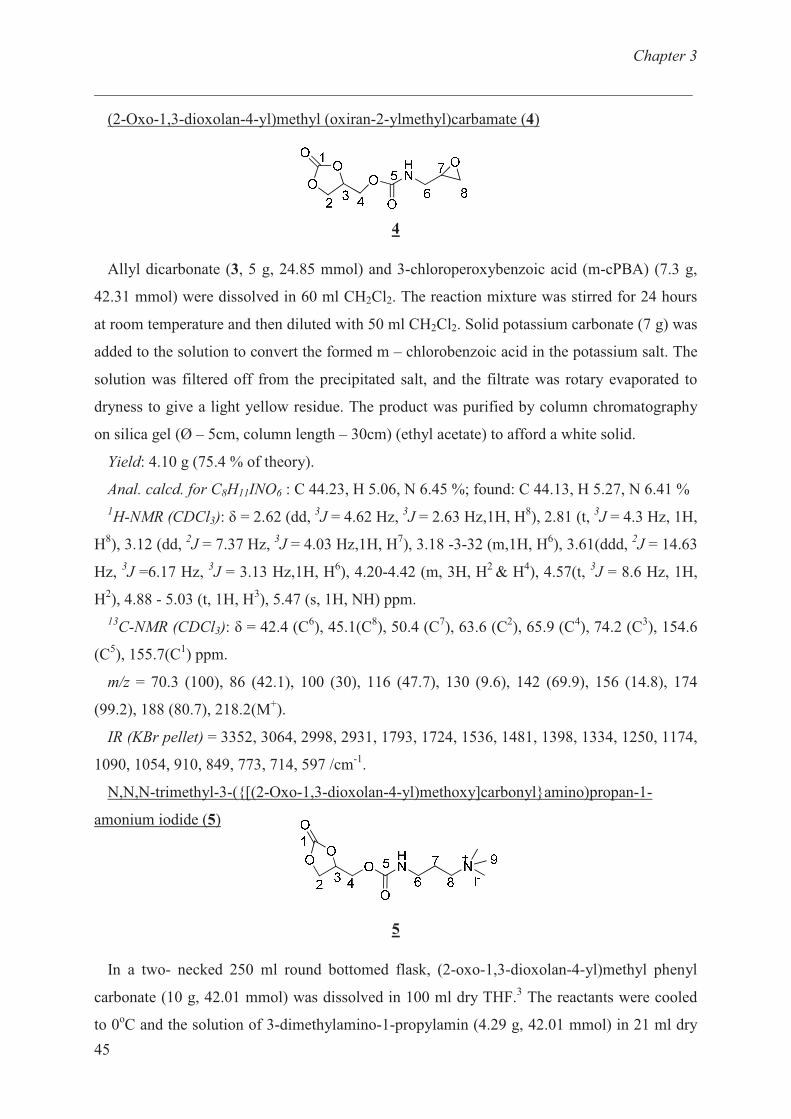
Chapter 3
___________________________________________________________________________
45
(2-Oxo-1,3-dioxolan-4-yl)methyl (oxiran-2-ylmethyl)carbamate (4)
4
Allyl dicarbonate (3, 5 g, 24.85 mmol) and 3-chloroperoxybenzoic acid (m-cPBA) (7.3 g,
42.31 mmol) were dissolved in 60 ml CH2Cl2. The reaction mixture was stirred for 24 hours
at room temperature and then diluted with 50 ml CH2Cl2. Solid potassium carbonate (7 g) was
added to the solution to convert the formed m – chlorobenzoic acid in the potassium salt. The
solution was filtered off from the precipitated salt, and the filtrate was rotary evaporated to
dryness to give a light yellow residue. The product was purified by column chromatography
on silica gel (Ø – 5cm, column length – 30cm) (ethyl acetate) to afford a white solid.
Yield: 4.10 g (75.4 % of theory).
Anal. calcd. for C8H11INO6 : C 44.23, H 5.06, N 6.45 %; found: C 44.13, H 5.27, N 6.41 %
1H-NMR (CDCl3): � = 2.62 (dd,
3J = 4.62 Hz,
3J = 2.63 Hz,1H, H
8), 2.81 (t,
3J = 4.3 Hz, 1H,
H8), 3.12 (dd,
2J = 7.37 Hz,
3J = 4.03 Hz,1H, H
7), 3.18 -3-32 (m,1H, H
6), 3.61(ddd,
2J = 14.63
Hz, 3J =6.17 Hz,
3J = 3.13 Hz,1H, H
6), 4.20-4.42 (m, 3H, H
2 & H
4), 4.57(t,
3J = 8.6 Hz, 1H,
H2), 4.88 - 5.03 (t, 1H, H
3), 5.47 (s, 1H, NH) ppm.
13C-NMR (CDCl3): � = 42.4 (C
6), 45.1(C
8), 50.4 (C
7), 63.6 (C
2), 65.9 (C
4), 74.2 (C
3), 154.6
(C5), 155.7(C
1) ppm.
m/z = 70.3 (100), 86 (42.1), 100 (30), 116 (47.7), 130 (9.6), 142 (69.9), 156 (14.8), 174
(99.2), 188 (80.7), 218.2(M+).
IR (KBr pellet) = 3352, 3064, 2998, 2931, 1793, 1724, 1536, 1481, 1398, 1334, 1250, 1174,
1090, 1054, 910, 849, 773, 714, 597 /cm-1
.
N,N,N-trimethyl-3-({[(2-Oxo-1,3-dioxolan-4-yl)methoxy]carbonyl}amino)propan-1-
amonium iodide (5)
5
In a two- necked 250 ml round bottomed flask, (2-oxo-1,3-dioxolan-4-yl)methyl phenyl
carbonate (10 g, 42.01 mmol) was dissolved in 100 ml dry THF.3 The reactants were cooled
to 0oC and the solution of 3-dimethylamino-1-propylamin (4.29 g, 42.01 mmol) in 21 ml dry
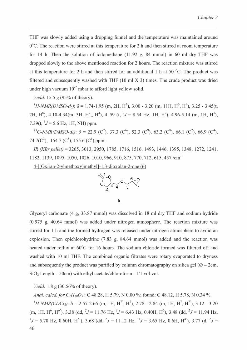
Chapter 3
___________________________________________________________________________
46
THF was slowly added using a dropping funnel and the temperature was maintained around
0oC. The reaction were stirred at this temperature for 2 h and then stirred at room temperature
for 14 h. Then the solution of iodomethane (11.92 g, 84 mmol) in 60 ml dry THF was
dropped slowly to the above mentioned reaction for 2 hours. The reaction mixture was stirred
at this temperature for 2 h and then stirred for an additional 1 h at 50 oC. The product was
filtered and subsequently washed with THF (10 ml X 3) times. The crude product was dried
under high vacuum 10-2
mbar to afford light yellow solid.
Yield: 15.5 g (95% of theory).
1H-NMR(DMSO-d6): � = 1.74-1.95 (m, 2H, H
7), 3.00 - 3.20 (m, 11H, H
6, H
9), 3.25 - 3.45(t,
2H, H8), 4.10-4.34(m, 3H, H
2,, H
4), 4..59 (t,
2J = 8.54 Hz, 1H, H
2), 4.96-5.14 (m, 1H, H
3),
7.39(t, 3J = 5.6 Hz, 1H, NH) ppm.
13C-NMR(DMSO-d6): � = 22.9 (C
7), 37.3 (C
6), 52.3 (C
9), 63.2 (C
8), 66.1 (C
2), 66.9 (C
4),
74.7(C3), 154.7 (C
5), 155.6 (C
1) ppm.
IR (KBr pellet) = 3265, 3013, 2950, 1785, 1716, 1516, 1493, 1446, 1395, 1348, 1272, 1241,
1182, 1139, 1095, 1050, 1026, 1010, 966, 910, 875, 770, 712, 615, 457 /cm-1
4-[(Oxiran-2-ylmethoxy)methyl]-1,3-dioxolan-2-one (6)
6
Glyceryl carbonate (4 g, 33.87 mmol) was dissolved in 18 ml dry THF and sodium hydride
(0.975 g, 40.64 mmol) was added under nitrogen atmosphere. The reaction mixture was
stirred for 1 h and the formed hydrogen was released under nitrogen atmosphere to avoid an
explosion. Then epichlorohydrine (7.83 g, 84.64 mmol) was added and the reaction was
heated under reflux at 60oC for 16 hours. The sodium chloride formed was filtered off and
washed with 10 ml THF. The combined organic filtrates were rotary evaporated to dryness
and subsequently the product was purified by column chromatography on silica gel (Ø – 2cm,
SiO2 Length – 50cm) with ethyl acetate/chloroform : 1/1 vol:vol.
Yield: 1.8 g (30.56% of theory).
Anal. calcd. for C7H10O5 : C 48.28, H 5.79, N 0.00 %; found: C 48.12, H 5.78, N 0.34 %.
1H-NMR(CDCl3): � = 2.57-2.66 (m, 1H, H
7’, H
7), 2.78 - 2.84 (m, 1H, H
7, H
7’), 3.12 - 3.20
(m, 1H, H6, H
6’), 3.38 (dd,
2J = 11.76 Hz,
3J = 6.43 Hz, 0.40H, H
5), 3.48 (dd,
2J = 11.94 Hz,
3J = 5.70 Hz, 0.60H, H
5’), 3.68 (dd,
2J = 11.12 Hz,
3J = 3.65 Hz, 0.6H, H
4’), 3.77 (d,
2J =
Chapter 3
___________________________________________________________________________
47
3.65, 0.8H, H4), 3.84 (dd,
2J = 11.12 Hz,
3J = 3.88 Hz, 0.60H, H
4’), 3.90 (dd,
2J = 11.86 Hz,
3J
= 2.45 Hz, 0.60H, H5’
), 3.94 (dd, 2J = 11.73 Hz,
3J = 2.37 Hz, 0.40H, H
5), 4.35 - 4.57 (m, 2H,
H2, H
2’), 4.78-4.90 (m, 1H, H
3) ppm.
13C-NMR(CDCl3): � = 43.8 (C
7), 43.8 (C
7’), 50.6, 50.7 (C
6, C
6’), 66.1 (C
2), 70.2 (C
4), 70.3
(C4’
), 71.9 (C5’
), 72.6 (C5), 75.0 (C
3), 154.9 (C
1) ppm.
m/z = 71 (14.8), 73 (70), 83 (7.7), 87 (100), 100 (8.9), 113 (5), 117 (7.3).
IR (KBr pellet) = 3565, 3062, 2998, 2923, 2506, 2340, 1789, 1549, 1480, 1397, 1337, 1309,
1255, 1172, 952, 908, 850, 773, 713, 611, 577, 534, 487, 416 / cm−1
.
Measurements
1H- and
13C-NMR spectra were recorded on a Bruker DPX-300 FT-NMR spectrometer at
300 MHz and 75 MHz respectively. Chloroform-d (CDCl3) and dimethylsulfoxide-d6
(DMSO-d6) were used as solvents, and tetramethylsilane (TMS) was used as internal
standard.
The infrared spectra were measured on a Thermo Nicolet Nexus 470 spectrometer with a re-
solution of 4 cm-1
. The samples were prepared as KBr pellets for the measurement in trans-
mission mode.
Carbon, hydrogen and nitrogen elemental analyses were performed on a Hearaeus CHN-O
Rapid Elementar Vario El instrument.
Mass Spectroscopy was carried on Finnigan MAT 95 high resolution mass spectrometer.
The samples were mixed with 3-Nitrobenzylalcohol matrix and were injected into the
spectrometer.
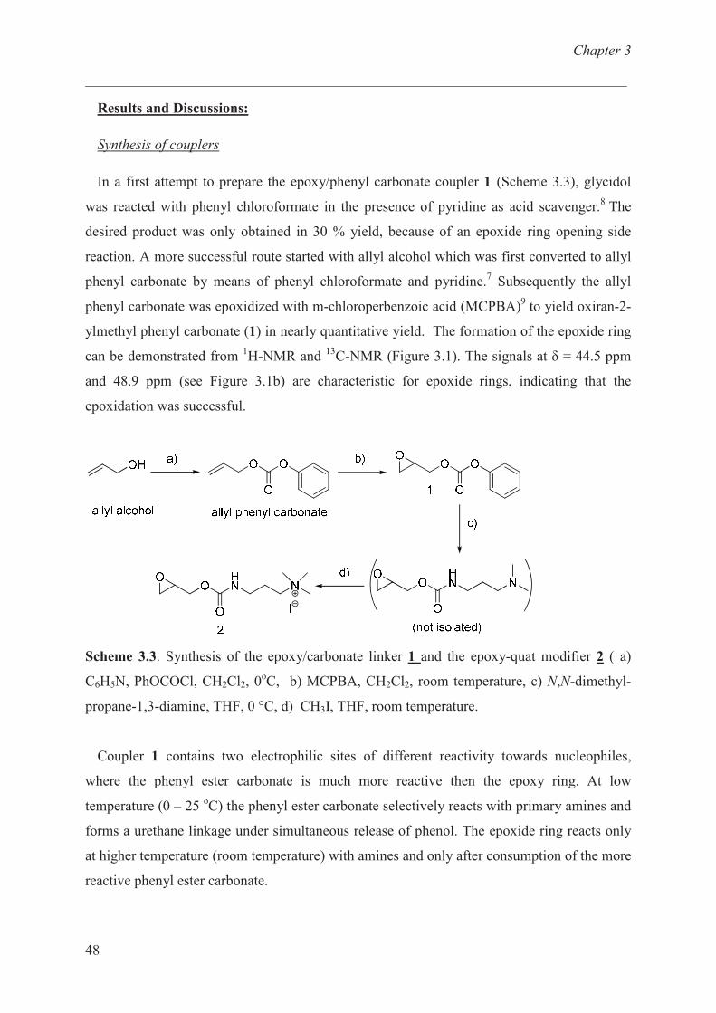
Chapter 3
___________________________________________________________________________
48
Results and Discussions:
Synthesis of couplers
In a first attempt to prepare the epoxy/phenyl carbonate coupler 1 (Scheme 3.3), glycidol
was reacted with phenyl chloroformate in the presence of pyridine as acid scavenger.8 The
desired product was only obtained in 30 % yield, because of an epoxide ring opening side
reaction. A more successful route started with allyl alcohol which was first converted to allyl
phenyl carbonate by means of phenyl chloroformate and pyridine.7 Subsequently the allyl
phenyl carbonate was epoxidized with m-chloroperbenzoic acid (MCPBA)9 to yield oxiran-2-
ylmethyl phenyl carbonate (1) in nearly quantitative yield. The formation of the epoxide ring
can be demonstrated from 1H-NMR and
13C-NMR (Figure 3.1). The signals at � = 44.5 ppm
and 48.9 ppm (see Figure 3.1b) are characteristic for epoxide rings, indicating that the
epoxidation was successful.
Scheme 3.3. Synthesis of the epoxy/carbonate linker 1 and the epoxy-quat modifier 2 ( a)
C6H5N, PhOCOCl, CH2Cl2, 0oC, b) MCPBA, CH2Cl2, room temperature, c) N,N-dimethyl-
propane-1,3-diamine, THF, 0 °C, d) CH3I, THF, room temperature.
Coupler 1 contains two electrophilic sites of different reactivity towards nucleophiles,
where the phenyl ester carbonate is much more reactive then the epoxy ring. At low
temperature (0 – 25 oC) the phenyl ester carbonate selectively reacts with primary amines and
forms a urethane linkage under simultaneous release of phenol. The epoxide ring reacts only
at higher temperature (room temperature) with amines and only after consumption of the more
reactive phenyl ester carbonate.
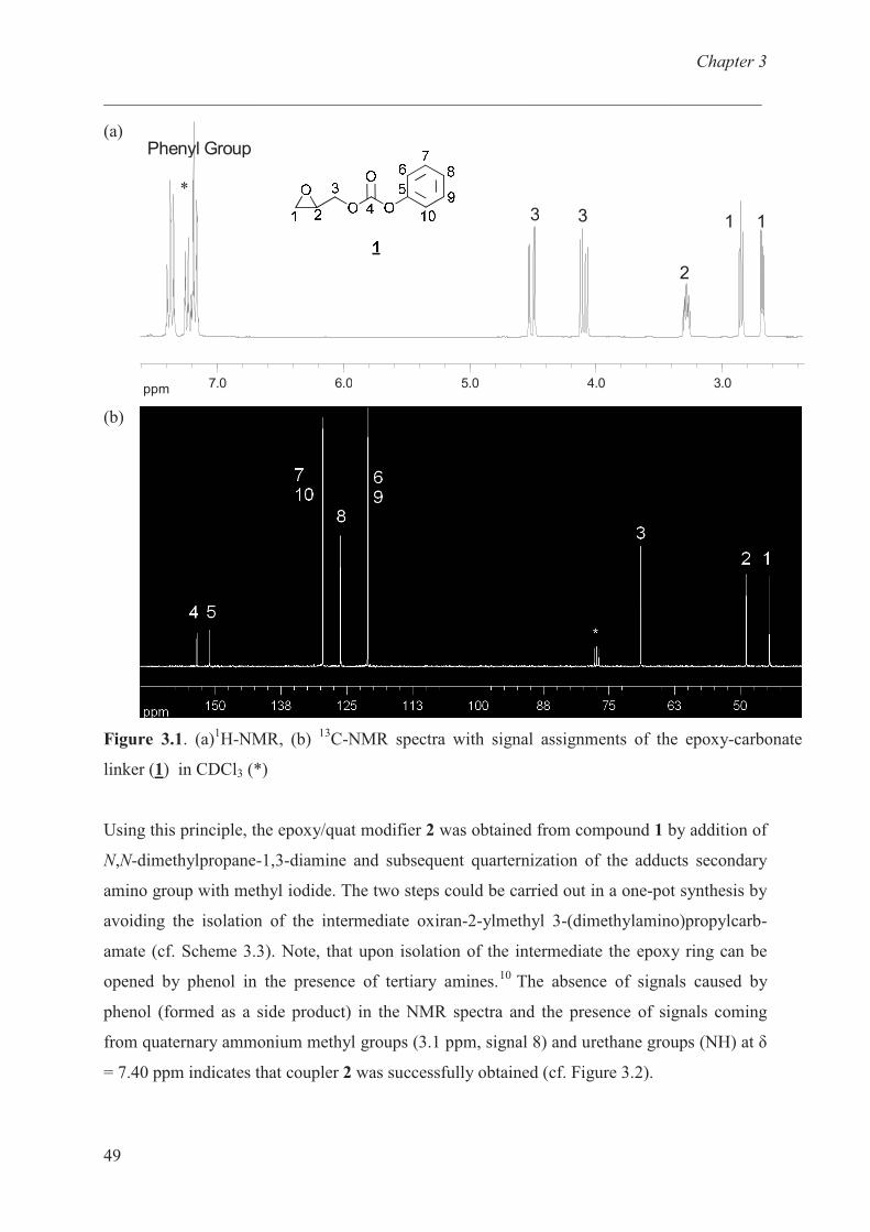
Chapter 3
___________________________________________________________________________
49
(a)
ppm 3.04.05.06.07.0
11
2
33
Phenyl Group
(b)
Figure 3.1. (a)1H-NMR, (b)
13C-NMR spectra with signal assignments of the epoxy-carbonate
linker (1) in CDCl3 (*)
Using this principle, the epoxy/quat modifier 2 was obtained from compound 1 by addition of
N,N-dimethylpropane-1,3-diamine and subsequent quarternization of the adducts secondary
amino group with methyl iodide. The two steps could be carried out in a one-pot synthesis by
avoiding the isolation of the intermediate oxiran-2-ylmethyl 3-(dimethylamino)propylcarb-
amate (cf. Scheme 3.3). Note, that upon isolation of the intermediate the epoxy ring can be
opened by phenol in the presence of tertiary amines.10
The absence of signals caused by
phenol (formed as a side product) in the NMR spectra and the presence of signals coming
from quaternary ammonium methyl groups (3.1 ppm, signal 8) and urethane groups (NH) at �
= 7.40 ppm indicates that coupler 2 was successfully obtained (cf. Figure 3.2).
*
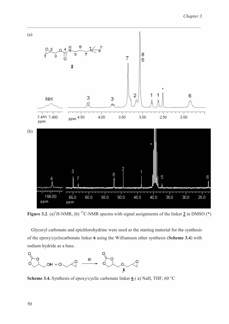
Chapter 3
___________________________________________________________________________
50
(a)
(b)
Figure 3.2. (a)1H-NMR, (b)
13C-NMR spectra with signal assignments of the linker 2 in DMSO (*)
Glyceryl carbonate and epichlorohydrine were used as the starting material for the synthesis
of the epoxy/cyclocarbonate linker 6 using the Williamson ether synthesis (Scheme 3.4) with
sodium hydride as a base.
Scheme 3.4. Synthesis of epoxy/cyclic carbonate linker 6 ( a) NaH, THF, 60 °C
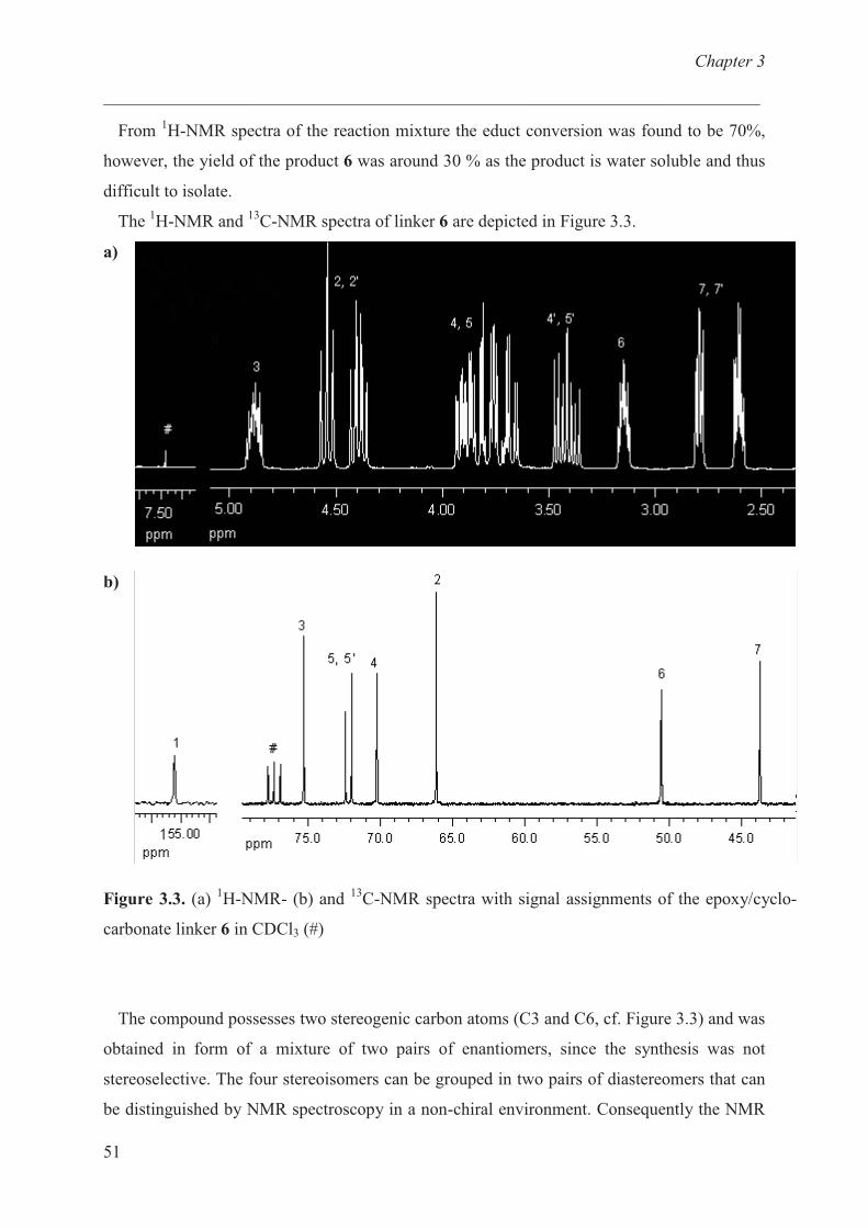
Chapter 3
___________________________________________________________________________
51
From 1H-NMR spectra of the reaction mixture the educt conversion was found to be 70%,
however, the yield of the product 6 was around 30 % as the product is water soluble and thus
difficult to isolate.
The 1H-NMR and
13C-NMR spectra of linker 6 are depicted in Figure 3.3.
a)
b)
Figure 3.3. (a) 1H-NMR- (b) and
13C-NMR spectra with signal assignments of the epoxy/cyclo-
carbonate linker 6 in CDCl3 (#)
The compound possesses two stereogenic carbon atoms (C3 and C6, cf. Figure 3.3) and was
obtained in form of a mixture of two pairs of enantiomers, since the synthesis was not
stereoselective. The four stereoisomers can be grouped in two pairs of diastereomers that can
be distinguished by NMR spectroscopy in a non-chiral environment. Consequently the NMR
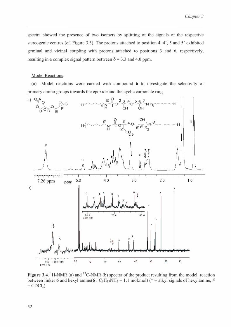
Chapter 3
___________________________________________________________________________
52
NH
O
O
OH
O NH
OH11 11
9
10
1
2 3 4 5 6 7
8O
O
O
O
OA
B C D EF
G
* NH
O
O119'
1'O
OH
N
2OH
2'
3' 4'
5' 6' 7'
8'11
spectra showed the presence of two isomers by splitting of the signals of the respective
stereogenic centres (cf. Figure 3.3). The protons attached to position 4, 4’, 5 and 5’ exhibited
geminal and vicinal coupling with protons attached to positions 3 and 6, respectively,
resulting in a complex signal pattern between δ = 3.3 and 4.0 ppm.
Model Reactions:
(a) Model reactions were carried with compound 6 to investigate the selectivity of
primary amino groups towards the epoxide and the cyclic carbonate ring.
a)
b)
Figure 3.4. 1H-NMR (a) and
13C-NMR (b) spectra of the product resulting from the model reaction
between linker 6 and hexyl amine(6 : C6H13NH2 = 1:1 mol:mol) (* = alkyl signals of hexylamine, #
= CDCl3)
7.26 ppm
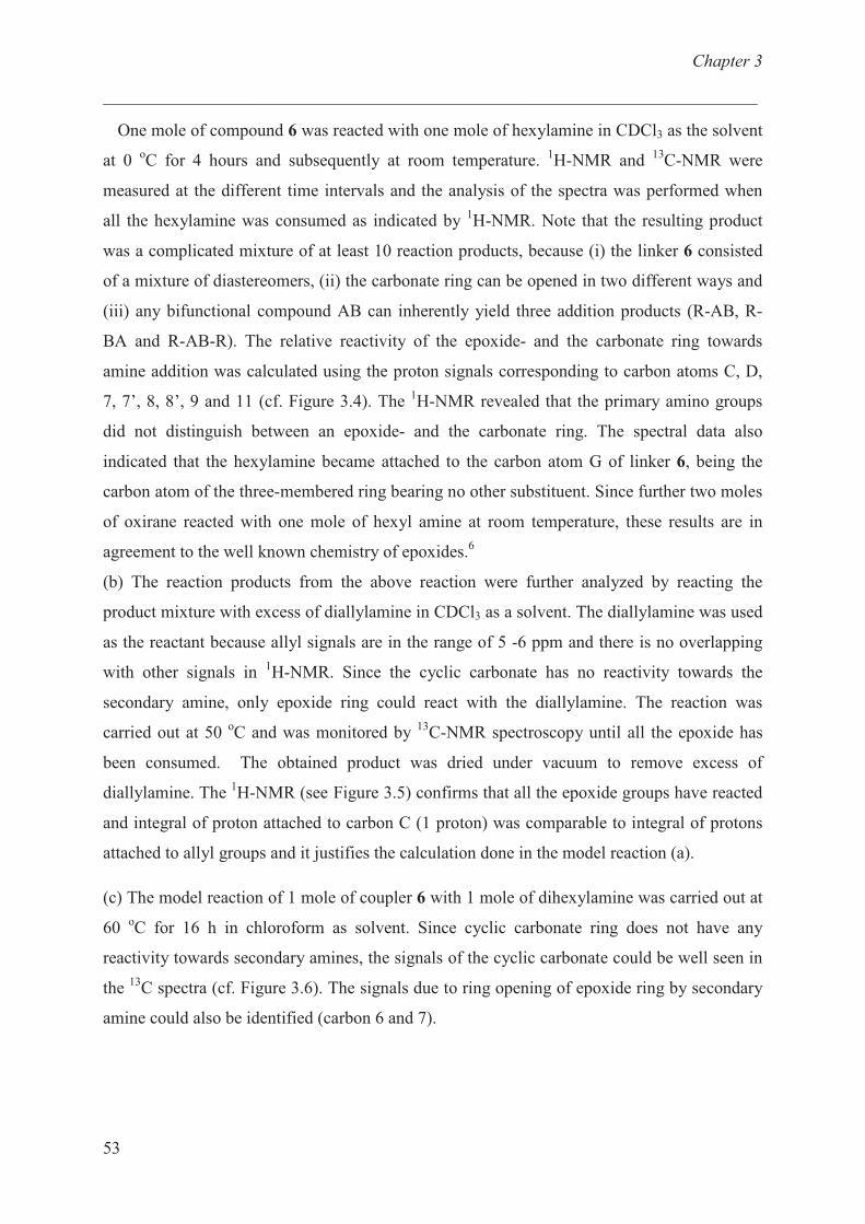
Chapter 3
___________________________________________________________________________
53
One mole of compound 6 was reacted with one mole of hexylamine in CDCl3 as the solvent
at 0 oC for 4 hours and subsequently at room temperature.
1H-NMR and
13C-NMR were
measured at the different time intervals and the analysis of the spectra was performed when
all the hexylamine was consumed as indicated by 1H-NMR. Note that the resulting product
was a complicated mixture of at least 10 reaction products, because (i) the linker 6 consisted
of a mixture of diastereomers, (ii) the carbonate ring can be opened in two different ways and
(iii) any bifunctional compound AB can inherently yield three addition products (R-AB, R-
BA and R-AB-R). The relative reactivity of the epoxide- and the carbonate ring towards
amine addition was calculated using the proton signals corresponding to carbon atoms C, D,
7, 7’, 8, 8’, 9 and 11 (cf. Figure 3.4). The 1H-NMR revealed that the primary amino groups
did not distinguish between an epoxide- and the carbonate ring. The spectral data also
indicated that the hexylamine became attached to the carbon atom G of linker 6, being the
carbon atom of the three-membered ring bearing no other substituent. Since further two moles
of oxirane reacted with one mole of hexyl amine at room temperature, these results are in
agreement to the well known chemistry of epoxides.6
(b) The reaction products from the above reaction were further analyzed by reacting the
product mixture with excess of diallylamine in CDCl3 as a solvent. The diallylamine was used
as the reactant because allyl signals are in the range of 5 -6 ppm and there is no overlapping
with other signals in 1H-NMR. Since the cyclic carbonate has no reactivity towards the
secondary amine, only epoxide ring could react with the diallylamine. The reaction was
carried out at 50 oC and was monitored by
13C-NMR spectroscopy until all the epoxide has
been consumed. The obtained product was dried under vacuum to remove excess of
diallylamine. The 1H-NMR (see Figure 3.5) confirms that all the epoxide groups have reacted
and integral of proton attached to carbon C (1 proton) was comparable to integral of protons
attached to allyl groups and it justifies the calculation done in the model reaction (a).
(c) The model reaction of 1 mole of coupler 6 with 1 mole of dihexylamine was carried out at
60 oC for 16 h in chloroform as solvent. Since cyclic carbonate ring does not have any
reactivity towards secondary amines, the signals of the cyclic carbonate could be well seen in
the 13
C spectra (cf. Figure 3.6). The signals due to ring opening of epoxide ring by secondary
amine could also be identified (carbon 6 and 7).
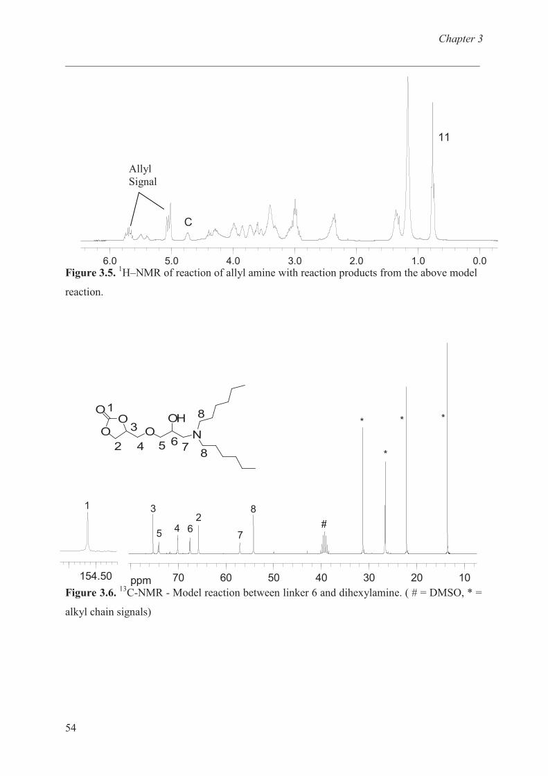
Chapter 3
___________________________________________________________________________
54
Allyl
Signal
0.01.02.03.04.05.06.0
11
C
ppm 10203040506070
3
45
26
7
8
#
*
*
* *
154.50
1
OO
O
O
1
2
3
4
OH
N5 6
7
8
8
Figure 3.5.1H–NMR of reaction of allyl amine with reaction products from the above model
reaction.
Figure 3.6.13
C-NMR - Model reaction between linker 6 and dihexylamine. ( # = DMSO, * =
alkyl chain signals)
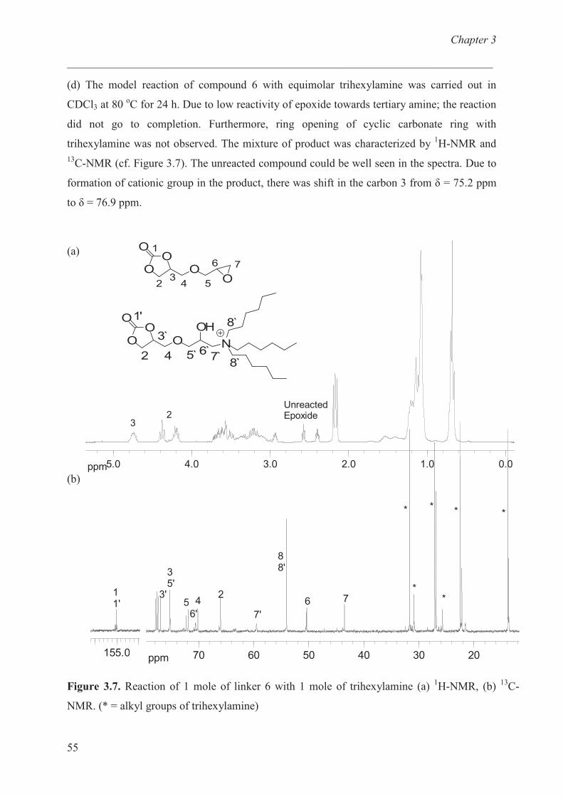
Chapter 3
___________________________________________________________________________
55
ppm 0.01.02.03.04.05.0
3
UnreactedEpoxide2
OO
O
O
1'
2
3̀
4
OH
N5̀ 6̀
7̀
8̀
8̀
OO O
O
O 1
23
4 5
6 7
(d) The model reaction of compound 6 with equimolar trihexylamine was carried out in
CDCl3 at 80 oC for 24 h. Due to low reactivity of epoxide towards tertiary amine; the reaction
did not go to completion. Furthermore, ring opening of cyclic carbonate ring with
trihexylamine was not observed. The mixture of product was characterized by 1H-NMR and
13C-NMR (cf. Figure 3.7). The unreacted compound could be well seen in the spectra. Due to
formation of cationic group in the product, there was shift in the carbon 3 from � = 75.2 ppm
to � = 76.9 ppm.
(a)
(b)
ppm 203040506070
3'
35'
56'
42
7'
88'
6 7*
* * *
*
155.0
11'
*
Figure 3.7. Reaction of 1 mole of linker 6 with 1 mole of trihexylamine (a) 1H-NMR, (b)
13C-
NMR. (* = alkyl groups of trihexylamine)
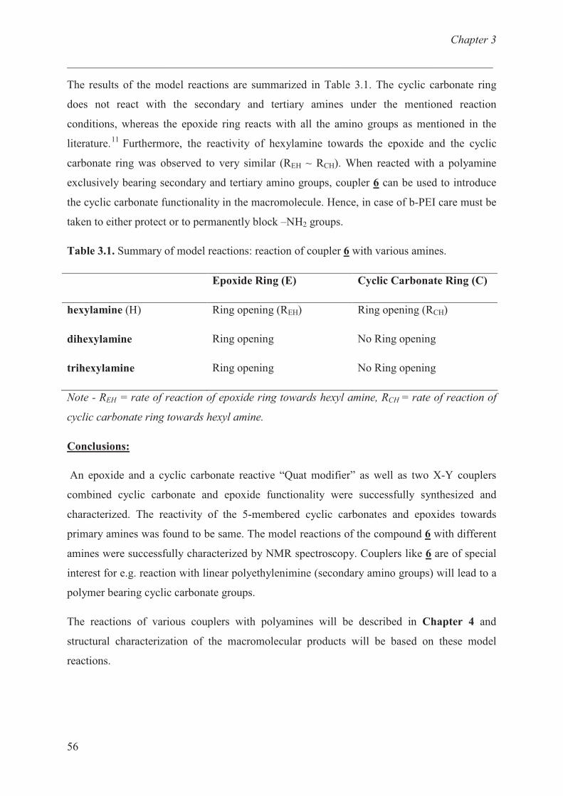
Chapter 3
___________________________________________________________________________
56
The results of the model reactions are summarized in Table 3.1. The cyclic carbonate ring
does not react with the secondary and tertiary amines under the mentioned reaction
conditions, whereas the epoxide ring reacts with all the amino groups as mentioned in the
literature.11
Furthermore, the reactivity of hexylamine towards the epoxide and the cyclic
carbonate ring was observed to very similar (REH ~ RCH). When reacted with a polyamine
exclusively bearing secondary and tertiary amino groups, coupler 6 can be used to introduce
the cyclic carbonate functionality in the macromolecule. Hence, in case of b-PEI care must be
taken to either protect or to permanently block –NH2 groups.
Table 3.1. Summary of model reactions: reaction of coupler 6 with various amines.
Epoxide Ring (E) Cyclic Carbonate Ring (C)
hexylamine (H)
dihexylamine
trihexylamine
Ring opening (REH)
Ring opening
Ring opening
Ring opening (RCH)
No Ring opening
No Ring opening
Note - REH = rate of reaction of epoxide ring towards hexyl amine, RCH = rate of reaction of
cyclic carbonate ring towards hexyl amine.
Conclusions:
An epoxide and a cyclic carbonate reactive “Quat modifier” as well as two X-Y couplers
combined cyclic carbonate and epoxide functionality were successfully synthesized and
characterized. The reactivity of the 5-membered cyclic carbonates and epoxides towards
primary amines was found to be same. The model reactions of the compound 6 with different
amines were successfully characterized by NMR spectroscopy. Couplers like 6 are of special
interest for e.g. reaction with linear polyethylenimine (secondary amino groups) will lead to a
polymer bearing cyclic carbonate groups.
The reactions of various couplers with polyamines will be described in Chapter 4 and
structural characterization of the macromolecular products will be based on these model
reactions.
Chapter 3
___________________________________________________________________________
57
References:
1 Sanchez, C. G.; Quesada, M. G.; Orden, M. U.; Urreaga, J. M. J. Appl. Polym. Sci. 2008,
110, 2555.
2 Peng, Q:, Zhong; Z.; Zhuo, R. Bioconjugate Chem. 2008, 19, 499.
3 Pasquier, N.; Keul, H.; Moeller, M. Designed Monomers and Polymers 2005, 8, 679.
4 Moeller, M.; Beginn, U.; Keul, H.; Thomas, H. European Patent 2006, EP 2005-7306.
5 Waerder, Y. diploma thesis, RWTH University 2006.
6 Parker, R. E.; Isaacs, N. S. Chemical Reviews (Washington, DC, United States) 1959, 59,
737.
7 Pittelkow, M.; Lewinsky, R.; Christensen, J. B. Synthesis 2002, 15, 2195.
8 Jansen, J. F. G. A.; Dias, A. A.; Dorschu, M.; Coussens, B. Macromolecules 2003, 36, 3861.
9 Ruano, J. L. G.; Fajardo, C.; Fraile, A.; Martın, M. R. J. Org. Chem. 2005, 70, 4300.
10 Stephenson, O. J. Chem. Soc. 1954, 1571.
11 Hansson, J. Svensk Kem. Tid. 1948, 60, 183.
Chapter 4
___________________________________________________________________________
58
Chapter 4: Quat-Primer' Polymers bearing cationic
and reactive groups: synthesis, characterization and
application.
Introduction:
Carbon fibres have become one of the most important reinforcing materials, being
characterized by extremely high strength and modulus. Carbon fibre – epoxy composites are
used in numerous aerospace, marine and recreational applications. The interface between
reinforcing fibres and polymeric matrices in composite materials is the controlling factor in
obtaining optimum mechanical properties.1-4
The function of the interface is to transmit stress
from the matrix to the reinforcing fibre. But the carbon fibre surface which is characterized by
low wettability and chemical activity exhibits weak adhesion to an epoxy matrix. A universal
method to increase the surface polarity of carbon fibres is to modify their surface to increase
the hydrophilicity of the fibre.5 The oxidative methods for the modification of carbon fibre
surfaces include oxidation in different types of plasma6-8
, oxidation in air9, electrochemical
oxidation10
and wet chemical methods, such as immersing in phosphoric acid or boiling11,12
in
nitric acid and intercalation13
. Drzal et al. studied the effect of oxidizing surface treatments on
carbon fibres and concluded that contribution to interfacial adhesion of covalent bonds
formed between carboxylic groups present on the oxidized fibre surfaces and epoxide groups
in the epoxy matrix was very small.14
They also studied the effect of epoxy based coatings on
the interfacial shear strength and concluded that although there is improvement in the
interfacial strength but the failure mode is no longer interfacial.15
To have good adhesion
between fibre and matrix , fibres are generally oxidized and coated with thin monomeric films
(100 – 200 nm thick) or coated with thin polymeric films from solutions.16,17
Sizing has an
adhesion and wetting promotion function but is particularly important for facilitating fibre
handling during composite manufacture or acting as a lubricant to prevent fibre damage.
In the present study highly oriented pyrolytic graphite (HOPG) was used as model substrate,
due to structural similarity of the carbon fibre and HOPG. HOPG consists of two dimensional
solid layers with strong covalent bonding within each layer and only weak van der Waals
interactions between neighboring layers.18
Several studies have shown that nanometer to
Chapter 4
___________________________________________________________________________
59
micrometer sized surface pits may form on HOPG surface upon oxidation; the pit size, its
number density, and its shape are dependent on the plasma gas mixture, temperature, pressure
and treatment time.19-20
Rabe et al. studied the thermal oxidation of the basal plane of
graphite in the presence of molecular oxygen allowing the variation of surface roughness in a
well defined way.21-23
Surface functionalization of HOPG, using low-energy plasma
environments was performed to attach chemical groups at the top most layer of the surface
Scanning force microscopy (SFM) was used for surface characterization of treated HOPG.
This study deals with the interaction of Quat-Primer functional polymers and HOPG. The
primers were prepared by ring opening reaction of functional five-membered cyclic
carbonates with poly(ethylene imine). The function of the primer polymers is (i) to bind to the
surface of carbon fibres via electrostatic interactions and (ii) to supply epoxy- or cyclic
carbonate groups that can copolymerize with the amine components of epoxy resins during
the curing step. The concept was to couple two different amines via the dicarbonate linker (2-
oxo-1,3-dioxolan-4-yl)methyl phenyl carbonate.24-26
This carbonate coupler posesses two
electrophilic sites of different reactivity. At low temperatures (0 - 25 oC), the phenyl ester
carbonate reacts with a first amine whereas the cyclic carbonate only reacts with a second
amine under ring opening at elevated temperature after full consumption of the phenyl ester
carbonate. The surface morphology of the polymers covered HOPG was studied by SFM and
the interfacial adhesion between functionalized carbon fibre sized with Quat-Primer Polymers
and the epoxy matrix were investigated using the Kelley – Tyson fragmentation test.
Materials and Methods:
Materials
Poly(ethylene imine) (b-PEI, Mw approx. 25000 g/mol by light scattering (LS), Mn approx.
10000 g/mol by gel permeation chromatography (GPC), water free, Aldrich),
tetraethylenepentamine (TEPA, Aldrich), were used as received. The couplers prepared in
Chapter 3 are used to functionalize b-PEI. All solvents were distilled before using.
ZYB grade high ordered pyrolytic graphite (HOPG) was obtained from advance ceramics;
Inc. Substrates were obtained by cleavage from adhesive tape just prior to plasma treatment.
The carbon fibre was a high modulus PAN based sized carbon fibre, UTS-5631 from Tenax
(nominal tensile strength = 4800 MPa, nominal fibre diameter is 7�m, 12.000 fibres/bundle).
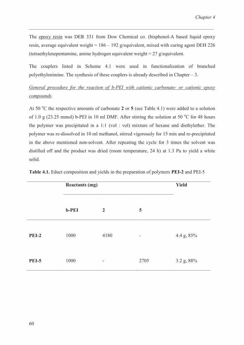
Chapter 4
___________________________________________________________________________
60
The epoxy resin was DER 331 from Dow Chemical co. (bisphenol-A based liquid epoxy
resin, average equivalent weight = 186 – 192 g/equivalent, mixed with curing agent DEH 226
(tetraethylenepentamine, amine hydrogen equivalent weight = 27 g/equivalent.
The couplers listed in Scheme 4.1 were used in functionalization of branched
polyethylenimine. The synthesis of these couplers is already described in Chapter – 3.
General procedure for the reaction of b-PEI with cationic carbonate- or cationic epoxy
compounds.
At 50 oC the respective amounts of carbonate 2 or 5 (see Table 4.1) were added to a solution
of 1.0 g (23.25 mmol) b-PEI in 10 ml DMF. After stirring the solution at 50 oC for 48 hours
the polymer was precipitated in a 1:1 (vol : vol) mixture of hexane and diethylether. The
polymer was re-dissolved in 10 ml methanol, stirred vigorously for 15 min and re-precipitated
in the above mentioned non-solvent. After repeating the cycle for 3 times the solvent was
distilled off and the product was dried (room temperature, 24 h) at 1.3 Pa to yield a white
solid.
Table 4.1. Educt composition and yields in the preparation of polymers PEI-2 and PEI-5
Reactants (mg)
b-PEI 2 5
Yield
PEI-2 1000 4180 - 4.4 g, 85%
PEI-5 1000 - 2705 3.2 g, 88%

Chapter 4
___________________________________________________________________________
61
General procedure to functionalize modified b-PEI with (2-oxo-1,3-dioxolan-4-yl)methyl
(oxiran-2-ylmethyl)carbamate (4) or 4-[(oxiran-2-ylmethoxy)methyl]-1,3-dioxolan-2-one (6)
To a solution of 1000 mg of modified PEI -5 in 10 ml DMF the required amount of the
epoxy- or cyclic carbonate linker (4 or 6) was added (see Table 4.2) and stirred at 50 oC for 48
hours and was precipitated in a 1:1 (vol : vol) mixture of hexane and diethylether.
Table 4.2. Educt composition and yields in the preparation of polymers PEI-54 and PEI-56
Reactants (mg) Polymer
PEI-5 4 6
Yield
PEI-54
PEI-56
1000
1000
812
---
---
621
1.5 g, 86 %
1.3 g, 81%
The polymer was re-dissolved in 10 ml methanol, stirred vigorously for 15 min and re-
precipitated in the above mentioned non-solvent. After repeating the cycle for 3 times the
solvent was removed and the product was dried (room temperature, 24 h) at 1.3 Pa to yield a
white solid.
Measurements:
1H- and
13C-NMR spectra were recorded on a Bruker DPX-300 FT-NMR spectrometer at 300
MHz and 75 MHz respectively. Chloroform-d (CDCl3) and dimethylsulfoxide-d6 (DMSO-
d6) were used as solvents, and tetramethylsilane (TMS) was used as internal standard.
The infrared spectra were measured on a Thermo Nicolet Nexus 470 spectrometer with a re-
solution of 4 cm-1
. The samples were prepared as KBr pellets for the measurement in trans-
mission mode.
Viscosity measurements were carried out with polymer concentrations varying from 0.5 g/dl
to 1.5 g/dl in 0.5M sodium nitrate solution using a Ostwald capillary viscometer (Schott, Type
509 03) at 25 oC. The intrinsic viscosity [η] was calculated by means of the Huggins equation
Chapter 4
___________________________________________________________________________
62
ηred = [η] + [η]2 ⋅ kH ⋅ c (ηred = reduced viscosity, [η] = intrinsic viscosity = 'Staudinger
Index', kH = Huggins constant, c = polymer concentration).
The hydrodynamic diameter of the macromolecules was determined on a Zetasizer NanoZS
ZEN3500 dynamic light scattering system. The concentration of the polymer was 1 – 10 g/L
in 0.5M sodium nitrate solution.
Differential scanning calorimetry (DSC) was performed with a Netzsch DSC 204 under nitro-
gen atmosphere with a heating rate of 10oC/min. Calibration was achieved using indium
standard samples, the sample mass was kept between 5 – 15 mg.
Thermogravimetric analyses (TGA) were performed on a Netzsch TG 209C thermobalance
with a TA System Controller TASC 414/4. The measurements were performed under nitrogen
atmosphere with a heating rate of 10oC/min. The sample mass was kept between 5 – 15 mg.
The surface modification of HOPG samples was carried out in a microwave plasma discharge
system, AK 330 Roth & Rau, using argon or oxygen/argon mixtures. The sample was placed
inside the chamber and became evacuated to a pressure of 10-3
bar. The treatment of HOPG
was done in two ways (i) in an argon atmosphere and (ii) in a mixture of argon and oxygen
(Ar : O2 – 1:1) atmosphere. The following process parameters were used: O2 and Ar gas flow,
30 ft3 / min each; working pressure, 0.4 mbar; power, 150W; treatment time 2 min.
The surface morphology of thin polymer films was investigated by atomic force microscopy
(AFM) at room temperature using a Solver SFM (NTMDT, Zelenograd, Moscow). Imaging
was done in the tapping mode using standard silicon cantilevers: Nanoworld Pointprobe NCH
f0 (330 kHz). The thin films were prepared by spin coating a volume of 40 �L from solutions
of the polymers, containing 0.04 wt% to 0.004 wt% of polymer in pure methanol at a rotation
rate of 2000 rpm.
Fabrication of Composite Specimens
(a) Fabrication of Steel and Rubber Molds
First, a mild steel master of dogbone-shape was machined with a length of 16 mm, a width of
the core of 2 mm and a height of 2 mm. Silicone rubber (Rhodorsil RTV 3450A, Rhodia
Silicon GmbH) was used for transferring the masters shape to a mould with a cavity of 16 x 2
x 2 mm3.
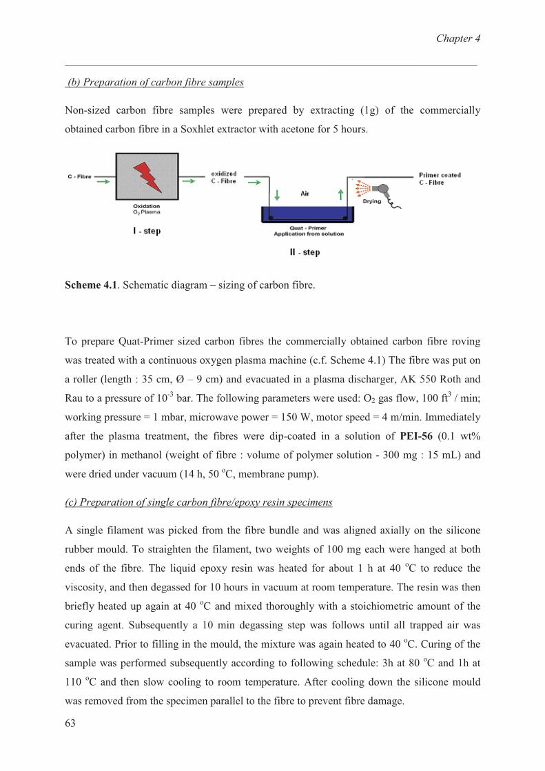
Chapter 4
___________________________________________________________________________
63
(b) Preparation of carbon fibre samples
Non-sized carbon fibre samples were prepared by extracting (1g) of the commercially
obtained carbon fibre in a Soxhlet extractor with acetone for 5 hours.
Scheme 4.1. Schematic diagram – sizing of carbon fibre.
To prepare Quat-Primer sized carbon fibres the commercially obtained carbon fibre roving
was treated with a continuous oxygen plasma machine (c.f. Scheme 4.1) The fibre was put on
a roller (length : 35 cm, Ø – 9 cm) and evacuated in a plasma discharger, AK 550 Roth and
Rau to a pressure of 10-3
bar. The following parameters were used: O2 gas flow, 100 ft3 / min;
working pressure = 1 mbar, microwave power = 150 W, motor speed = 4 m/min. Immediately
after the plasma treatment, the fibres were dip-coated in a solution of PEI-56 (0.1 wt%
polymer) in methanol (weight of fibre : volume of polymer solution - 300 mg : 15 mL) and
were dried under vacuum (14 h, 50 oC, membrane pump).
(c) Preparation of single carbon fibre/epoxy resin specimens
A single filament was picked from the fibre bundle and was aligned axially on the silicone
rubber mould. To straighten the filament, two weights of 100 mg each were hanged at both
ends of the fibre. The liquid epoxy resin was heated for about 1 h at 40 oC to reduce the
viscosity, and then degassed for 10 hours in vacuum at room temperature. The resin was then
briefly heated up again at 40 oC and mixed thoroughly with a stoichiometric amount of the
curing agent. Subsequently a 10 min degassing step was follows until all trapped air was
evacuated. Prior to filling in the mould, the mixture was again heated to 40 oC. Curing of the
sample was performed subsequently according to following schedule: 3h at 80 oC and 1h at
110 oC and then slow cooling to room temperature. After cooling down the silicone mould
was removed from the specimen parallel to the fibre to prevent fibre damage.

Chapter 4
___________________________________________________________________________
64
d) Tensile and Photoelastic Measurements
The carbon single fibre / epoxy specimen were clamped in a Rheometric Scientific ‘minimat’
tensile testing device, mounted under a Zeiss Stemi – 2000c polarizing microscope, equipped
with a camera (Nikon Cooplix 4500, 4 mega pixels) facility mounted at the top. The images
were analyzed using Microsoft Photo Editor Software.
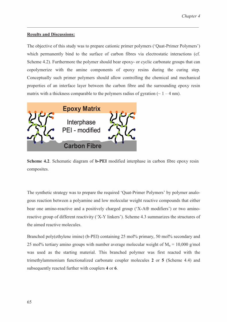
Chapter 4
___________________________________________________________________________
65
Results and Discussions:
The objective of this study was to prepare cationic primer polymers (‘Quat-Primer Polymers’)
which permanently bind to the surface of carbon fibres via electrostatic interactions (cf.
Scheme 4.2). Furthermore the polymer should bear epoxy- or cyclic carbonate groups that can
copolymerize with the amine components of epoxy resins during the curing step.
Conceptually such primer polymers should allow controlling the chemical and mechanical
properties of an interface layer between the carbon fibre and the surrounding epoxy resin
matrix with a thickness comparable to the polymers radius of gyration (~ 1 – 4 nm).
Carbon Fibre
Epoxy Matrix
Interphase
PEI - modified
Carbon FibreCarbon Fibre
Epoxy MatrixEpoxy Matrix
Interphase
PEI - modified
Scheme 4.2. Schematic diagram of b-PEI modified interphase in carbon fibre epoxy resin
composites.
The synthetic strategy was to prepare the required ‘Quat-Primer Polymers’ by polymer analo-
gous reaction between a polyamine and low molecular weight reactive compounds that either
bear one amino-reactive and a positively charged group (‘X-A⊕ modifiers’) or two amino-
reactive group of different reactivity (‘X-Y linkers’). Scheme 4.3 summarizes the structures of
the aimed reactive molecules.
Branched poly(ethylene imine) (b-PEI) containing 25 mol% primary, 50 mol% secondary and
25 mol% tertiary amino groups with number average molecular weight of Mn = 10,000 g/mol
was used as the starting material. This branched polymer was first reacted with the
trimethylammonium functionalized carbonate coupler molecules 2 or 5 (Scheme 4.4) and
subsequently reacted further with couplers 4 or 6.
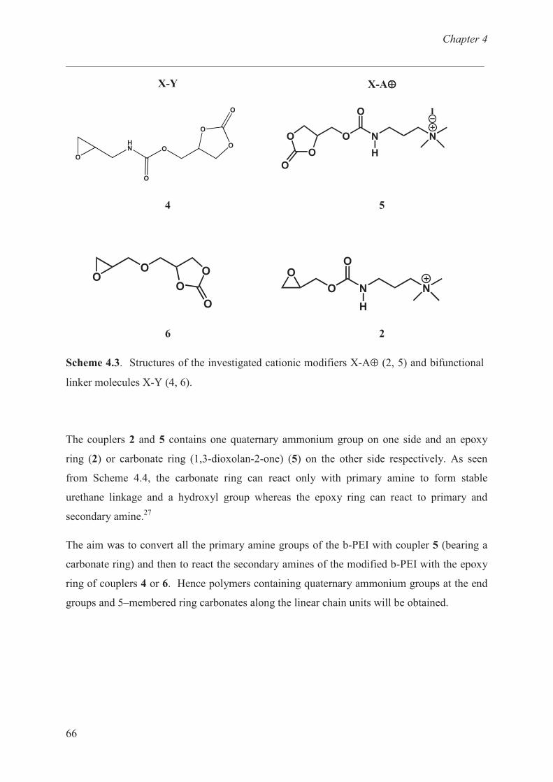
Chapter 4
___________________________________________________________________________
66
X-Y X-A⊕⊕⊕⊕
�
�� �
�
�
�
�
O N N
I
H
O
O
O
O
4 5
OO
O
O
O
O N N
H
OO
6 2
Scheme 4.3. Structures of the investigated cationic modifiers X-A⊕ (2, 5) and bifunctional
linker molecules X-Y (4, 6).
The couplers 2 and 5 contains one quaternary ammonium group on one side and an epoxy
ring (2) or carbonate ring (1,3-dioxolan-2-one) (5) on the other side respectively. As seen
from Scheme 4.4, the carbonate ring can react only with primary amine to form stable
urethane linkage and a hydroxyl group whereas the epoxy ring can react to primary and
secondary amine.27
The aim was to convert all the primary amine groups of the b-PEI with coupler 5 (bearing a
carbonate ring) and then to react the secondary amines of the modified b-PEI with the epoxy
ring of couplers 4 or 6. Hence polymers containing quaternary ammonium groups at the end
groups and 5–membered ring carbonates along the linear chain units will be obtained.
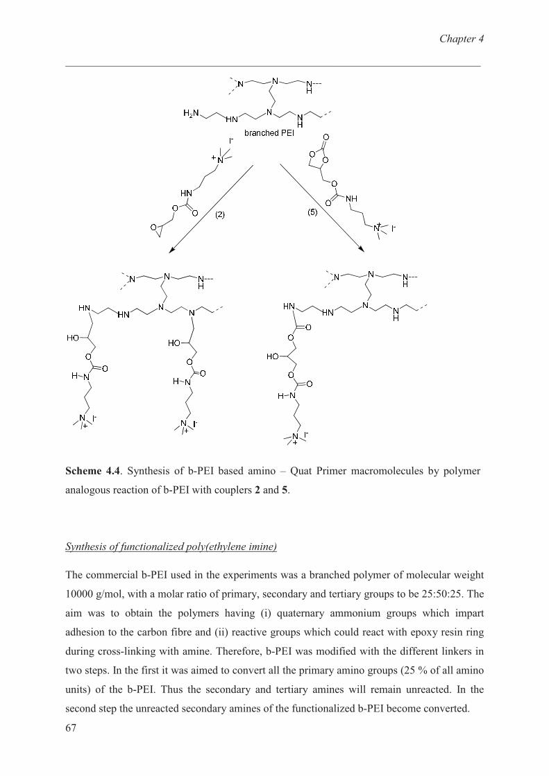
Chapter 4
___________________________________________________________________________
67
Scheme 4.4. Synthesis of b-PEI based amino – Quat Primer macromolecules by polymer
analogous reaction of b-PEI with couplers 2 and 5.
Synthesis of functionalized poly(ethylene imine)
The commercial b-PEI used in the experiments was a branched polymer of molecular weight
10000 g/mol, with a molar ratio of primary, secondary and tertiary groups to be 25:50:25. The
aim was to obtain the polymers having (i) quaternary ammonium groups which impart
adhesion to the carbon fibre and (ii) reactive groups which could react with epoxy resin ring
during cross-linking with amine. Therefore, b-PEI was modified with the different linkers in
two steps. In the first it was aimed to convert all the primary amino groups (25 % of all amino
units) of the b-PEI. Thus the secondary and tertiary amines will remain unreacted. In the
second step the unreacted secondary amines of the functionalized b-PEI become converted.

Chapter 4
___________________________________________________________________________
68
Based on the above principle b-PEI was first reacted with the cyclic carbonate 5. Hence the
primary amino groups in b-PEI (25% of all amino units) have been modified to 25 mol% of
quaternary ammonium groups (PEI-5). In the next step secondary amino groups in functio-
nalized b-PEI have been modified with carbonate linkers 4 or 6 to yield a degree of
functionalization of 75 % (with respect to all amino units in b-PEI) in PEI-54 and PEI-56,
letting only the tertiary amino groups of the branching units in the polymer backbone
unreacted.
All functionalized polymers were prepared in DMF at 60 oC reacting for 48 hours according
to the experimental procedure and using the amounts given in Table 4.1 and Table 4.2.
Characterization of functionalized poly(ethylene imine)s
The structures of the functionalized PEI’s were investigated by means of 1H-NMR,
13C-NMR
and IR spectroscopy. The NMR spectra of PEI-2, PEI-5 and PEI-56 and are shown in
Figures 4.1 - 4.3.
The 13
C-NMR spectra of PEI-2 (Figure 4.1) shows the characteristics peak of the hydroxyl
propyl moiety arising from the reacted oxirane ring (signals 9, 10 and 11).
Figure 4.1. 13
C-NMR spectra of PEI-2 in DMSO-d6 (* = residual solvent, # = DMSO)
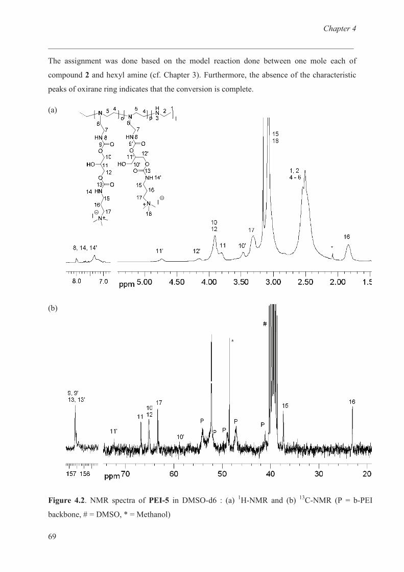
Chapter 4
___________________________________________________________________________
69
The assignment was done based on the model reaction done between one mole each of
compound 2 and hexyl amine (cf. Chapter 3). Furthermore, the absence of the characteristic
peaks of oxirane ring indicates that the conversion is complete.
(a)
(b)
Figure 4.2. NMR spectra of PEI-5 in DMSO-d6 : (a) 1H-NMR and (b)
13C-NMR (P = b-PEI
backbone, # = DMSO, * = Methanol)
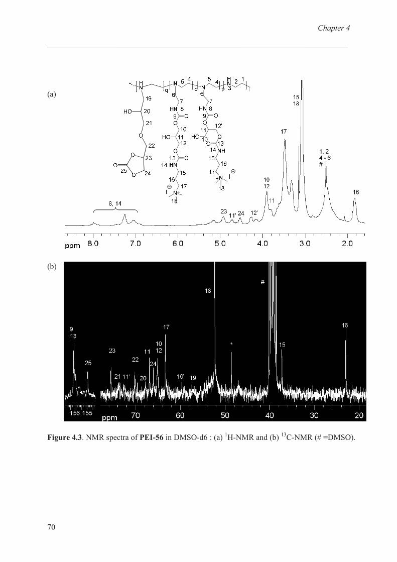
Chapter 4
___________________________________________________________________________
70
(a)
(b)
Figure 4.3. NMR spectra of PEI-56 in DMSO-d6 : (a) 1H-NMR and (b)
13C-NMR (# =DMSO).
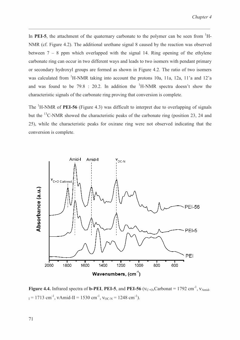
Chapter 4
___________________________________________________________________________
71
In PEI-5, the attachment of the quaternary carbonate to the polymer can be seen from 1H-
NMR (cf. Figure 4.2). The additional urethane signal 8 caused by the reaction was observed
between 7 – 8 ppm which overlapped with the signal 14. Ring opening of the ethylene
carbonate ring can occur in two different ways and leads to two isomers with pendant primary
or secondary hydroxyl groups are formed as shown in Figure 4.2. The ratio of two isomers
was calculated from 1H-NMR taking into account the protons 10a, 11a, 12a, 11’a and 12’a
and was found to be 79.8 : 20.2. In addition the 1H-NMR spectra doesn’t show the
characteristic signals of the carbonate ring proving that conversion is complete.
The 1H-NMR of PEI-56 (Figure 4.3) was difficult to interpret due to overlapping of signals
but the 13
C-NMR showed the characteristic peaks of the carbonate ring (position 23, 24 and
25), while the characteristic peaks for oxirane ring were not observed indicating that the
conversion is complete.
Figure 4.4. Infrared spectra of b-PEI, PEI-5, and PEI-56 (νC=O,Carbonat = 1792 cm-1
, νAmid-
I = 1713 cm-1
, νAmid-II = 1530 cm-1
, νOC-N = 1248 cm-1
).
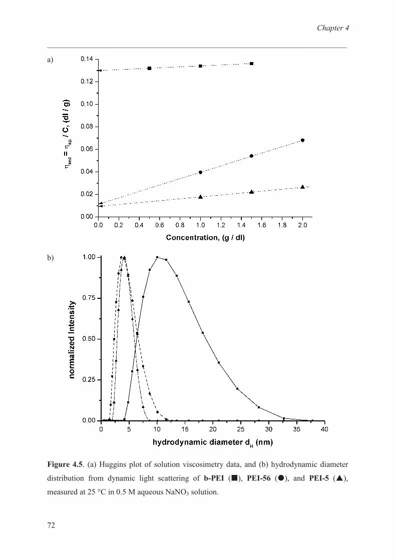
Chapter 4
___________________________________________________________________________
72
a)
b)
Figure 4.5. (a) Huggins plot of solution viscosimetry data, and (b) hydrodynamic diameter
distribution from dynamic light scattering of b-PEI (�), PEI-56 (�), and PEI-5 (�),
measured at 25 °C in 0.5 M aqueous NaNO3 solution.
Chapter 4
___________________________________________________________________________
73
Comparing the infrared spectra of PEI, PEI-5, and PEI-56 (see Figure 6) confirmed the
presence of amide groups (PEI-5, PEI-56) and cyclic carbonate units (PEI-56) in the macro-
molecules. The bands at 1248 cm-1
(OC-N - stretch), 1530 cm-1
(Amide-I) and 1660 cm-1
(Amide-II) are characteristic for –CO-NH- groups, while the band at 1791 cm-1
that appeared
only in PEI-56 was attributed to the >C=O stretching vibration of the cyclic carbonate ring.
Since the polymer analogous reaction started with b-PEI of <Mn> = 10000 g/mol, the spec-
troscopically measured degree of modifications inferred a molecular weight of <Mn> ≈ 25000
g/mol with PEI-5 and <Mn> ≈ 45000 g/mol with PEI-56. Figure 4.5a depicts the results from
viscosimetric measurements, performed in 0.5 M aqueous NaNO3 solution to screen the
Coulomb interaction and to avoid polyelectrolyte effects.
While an intrinsic viscosity of [η] = 0.13 dL/g was measured for the educt b-PEI the modified
products yielded intrinsic viscosities that were smaller for one order of magnitude (PEI-5: [η]
= 0.011 dL/g, PEI-56: [η] = 0.009 dL/g). This finding was supported by dynamic light
scattering measurements of the hydrodynamic diameter in the same solvent system (cf. Figure
4.5b) The measured hydrodynamic diameter dH of b-PEI, PEI-5, and PEI-56 were 10.5 nm,
4.2 nm, and 3.7 nm, respectively (cf. Table 4.3). Note, that the intrinsic viscosities are
proportional to approximately the third power of the hydrodynamic diameter (log[η] = -
3.56±0.07 + 2.6±0.2 ⋅ log dH).
Since it is well known that the employed ring-opening modification reactions cannot cleave
the polymer backbone, the observed reduction of the hydrodynamic diameter was not caused
by depolymerization or polymer degradation. It was hence assumed that strong, but short
ranged intramolecular interactions contract the modified macromolecules below the typical
radius of non-modified b-PEI. The interactions must be of short range, because at the applied
polymer concentrations (1 – 10 g/L) corresponding to average intermolecular distances in the
solutions of 12 – 25 nm, the intermolecular interactions were not sufficiently large to cause
association or precipitation. The sodium nitrate should have screened the Coulomb interaction
and impede the polyelectrolyte typical ion association. For these reasons it is assumed that
intramolecular hydrogen bonds between the introduced urethane-, and hydroxyl groups as
well as the macromolecular amine groups cause the observed contraction. Obviously this
contraction will bring all molecular weight determination methods to the fail that relay on
determination of molecular size parameters, like viscometry or, in particular, size exclusion
chromatography.
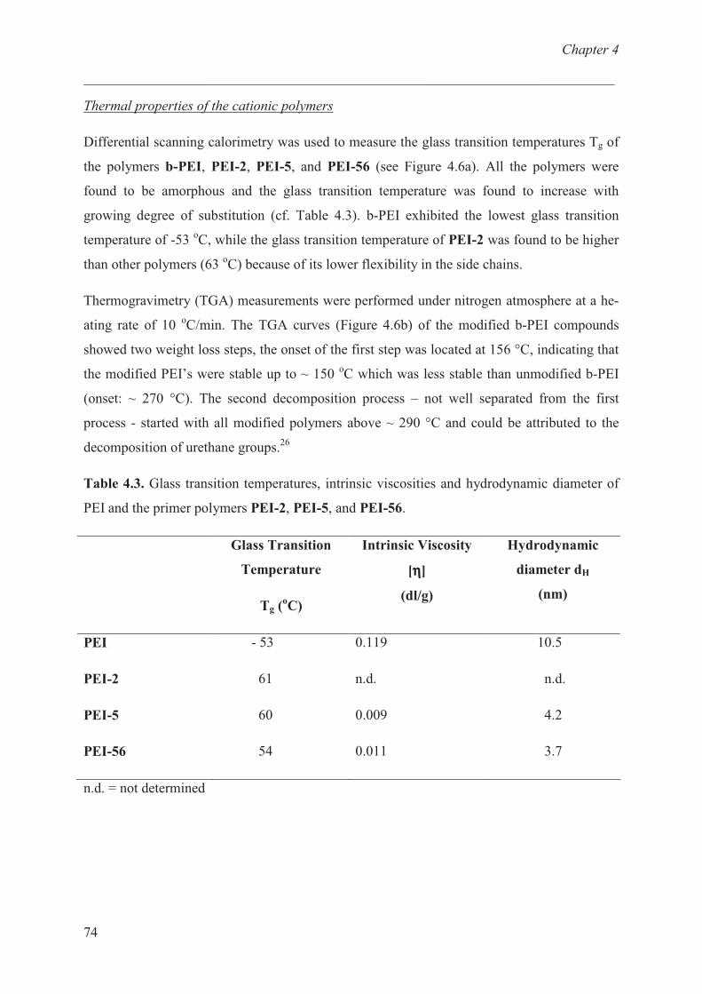
Chapter 4
___________________________________________________________________________
74
Thermal properties of the cationic polymers
Differential scanning calorimetry was used to measure the glass transition temperatures Tg of
the polymers b-PEI, PEI-2, PEI-5, and PEI-56 (see Figure 4.6a). All the polymers were
found to be amorphous and the glass transition temperature was found to increase with
growing degree of substitution (cf. Table 4.3). b-PEI exhibited the lowest glass transition
temperature of -53 oC, while the glass transition temperature of PEI-2 was found to be higher
than other polymers (63 oC) because of its lower flexibility in the side chains.
Thermogravimetry (TGA) measurements were performed under nitrogen atmosphere at a he-
ating rate of 10 oC/min. The TGA curves (Figure 4.6b) of the modified b-PEI compounds
showed two weight loss steps, the onset of the first step was located at 156 °C, indicating that
the modified PEI’s were stable up to ~ 150 oC which was less stable than unmodified b-PEI
(onset: ~ 270 °C). The second decomposition process – not well separated from the first
process - started with all modified polymers above ~ 290 °C and could be attributed to the
decomposition of urethane groups.26
Table 4.3. Glass transition temperatures, intrinsic viscosities and hydrodynamic diameter of
PEI and the primer polymers PEI-2, PEI-5, and PEI-56.
Glass Transition
Temperature
Tg (oC)
Intrinsic Viscosity
[ηηηη]
(dl/g)
Hydrodynamic
diameter dH
(nm)
PEI
PEI-2
PEI-5
PEI-56
- 53
61
60
54
0.119
n.d.
0.009
0.011
10.5
n.d.
4.2
3.7
n.d. = not determined
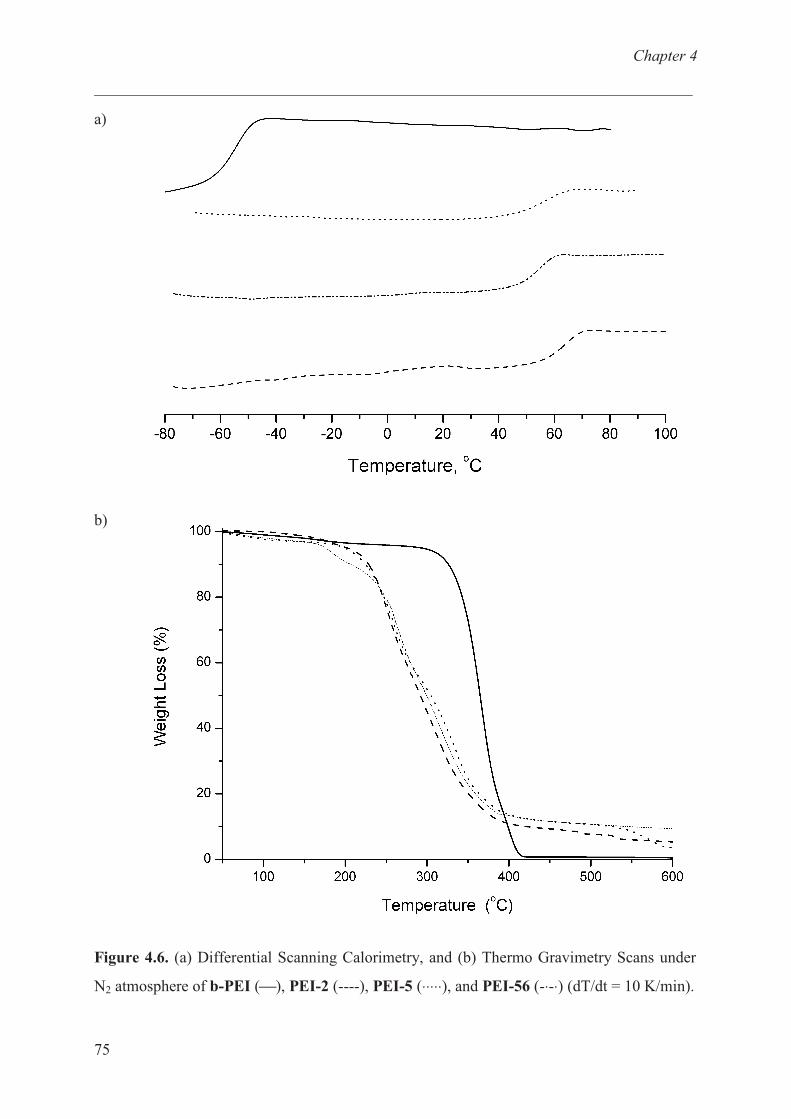
Chapter 4
___________________________________________________________________________
75
a)
b)
Figure 4.6. (a) Differential Scanning Calorimetry, and (b) Thermo Gravimetry Scans under
N2 atmosphere of b-PEI (), PEI-2 (----), PEI-5 (⋅⋅⋅⋅⋅), and PEI-56 (-⋅-⋅) (dT/dt = 10 K/min).
Chapter 4
___________________________________________________________________________
76
Adsorption on graphitic surfaces
In a first series of experiments thin films of PEI-56 were spin coated on highly oriented pyro-
lytic graphite (HOPG) as a model substrate. Although the interior of PAN-based carbon fibres
consist of turbostratic carbon instead of graphite, it is generally accepted that non-surface mo-
dified carbon fibres are covered by a thin sheath of graphitic basal plane structure (‘Onion
Skin’ model).28
HOPG consist of layers of two-dimensional sheets with strong covalent bonds
with in each layer (Young modulus in-plane: 1 TPa29
) and only weak van-der-Waals interacti-
ons between stacked layers (Young modulus perpendicular to plane: 34.6 GPa30
). Because of
the structural similarity between HOPG and the surface of non-modified carbon fibres, in ad-
dition to its close to perfect planarity, HOPG was selected as a suitable and easy to investigate
model substrate.
Figure 4.7a depicts a scanning force micrograph of PEI-56 coated from a 0.04 wt% solution
in methanol on non-treated, freshly cleaved HOPG. The polymer virtually did not spread but
formed isolated irregular shaped droplets and islands with non-uniform diameters from 40 to
about 400 nm. These droplets could be removed by a single washing step with methanol. In a
second series of experiments PEI-56 was coated under identical conditions on HOPG that
was pre-treated for 2 minutes with low-energy argon plasma. The plasma treatment conditions
were adjusted such way that any surface modification was limited to the topmost layers of the
surface.18
On this substrate the polymer became deposited in the form of small, partially in-
terconnected droplets with a more uniform size distribution of an average size around 50 - 60
nm (see Figure 4.7b). Figure 4.7c shows the scanning force image of PEI-56 coated from a
0.004 wt% solution in methanol onto a HOPG-substrate that has been pre-treated with oxygen
– argon plasma. In this picture the polymer film is hard to see; however, the steps originally
present at the HOPG surface can be recognized. The picture demonstrates that an ultra thin
polymer film was formed. Detailed scanning force investigations revealed the presence of a
continuous film of the polymer on the substrate with a thickness of 3 nm.
Subsequent to these measurements the sample depicted in Figure 4.7c was extracted for 2
hours with methanol in a Soxhlet extractor. No difference in film morphology and thickness
was found by means of scanning force microscopy after the extraction step (cf. Figure 4.7d),
indicating that the polymer became strongly bond to the substrate.

Chapter 4
___________________________________________________________________________
77
a) (b)
c) (d)
Figure 4.7. Scanning force micrographs of HOPG surfaces spin coated with methanolic PEI-56
solutions. (a) Non-treated HOPG (0.04 wt% PEI-56), (b) argon plasma treated HOPG (0.04 wt%
PEI-56), (c) argon / oxygen plasma treated HOPG (0.004 wt% PEI-56), (d) sample picture (c) after
extraction with methanol.
Obviously the highly polar PEI-56 polymer did neither wet, nor adhere well to the non-polar
HOPG surface. It is well documented that argon plasma treatment creates grooves with uni-
form spacing and congruent alignment at HOPG surfaces21,22
and that the edges of graphite
layers are more reactive than the damage-free basal planes. The argon plasma treatment im-
proved the wetting behaviour of PEI-56, possibly because the plasma increased the surface
Chapter 4
___________________________________________________________________________
78
roughness and allowed for a certain degree of oxidation when the sample was exposed to air
prior to the polymer coating. An argon / oxygen plasma not only generates structural defects,
but also produces oxygen containing species like ≡C-OH, >C=O and –COOH covalently
bound to the edges of the defects.31
These groups will increase the surface energy of the sub-
strate, create negative (partial) charges at its surface and allow for hydrogen bonding. The
combination of these effects seemed to cause a nearly perfect spreading of the positively
charged PEI-56 on the substrate and considerably improved the interaction between the poly-
mer and the HOPG surface. The model experiments showed that PEI-based ‘Quat-Primer
Polymers’ strongly adhered to roughened graphite surfaces bearing covalently fixed negative-
ly charged oxygen species. Since commercial carbon fibres become anodic oxidised subse-
quent to the carbonisation step and prior to seizing,32,33
strong adhesion of these polymers on
carbon fibres can also be expected.
High performance fibre/matrix composites can only be obtained if the matrix is effectively
able to transfer mechanical stress to the fibre. Hence, the strength at break of such composites
is highly dependent on the fibre matrix adhesion. Since on one hand the Quat-Primer Poly-
mers are expected to adhere well to carbon fibre surfaces and since on the other hand epoxy
resins are known to bind covalently to polyamines, the PEI based Quat-Primer polymers
conceptually offer a simple and rational mean to control the properties of the carbon fibre /
epoxy resin interface.
Carbon-Fibre / Epoxy Model Resins
To investigate the suitability of PEI based Quat-Primer Polymers as carbon fibre surface
modification agents, carbon fibre / epoxy resin composites were prepared from (i) de-seized
carbon fibres and (ii) from carbon fibres that were plasma treated to remove the size and
subsequently coated with a Quat-Primer Polymer. Single filaments were taken from a carbon
fibre bundle and embedded in a technically used epoxy resin system (cf. Experimental Part).
There are three main micromechanical tests which have been developed to evaluate interfacial
shear strength of single fibre composites namely single fibre pull out test34-36
, fragmentation
test37-43
and microbond test.44,45
The different techniques are based on specific sample
configurations and loading geometries, and thus involve different stress states at the interface.
The fibre pull out test is the most extensively used because of its simplicity but there are some
inherent drawbacks. The main problem with the pull out test is that the resin meniscus formed
on fibre makes the determination of embedded fibre length difficult. Moreover, since in pull
Chapter 4
___________________________________________________________________________
79
out tests the interfacial debonding force is directly related to embedded fibre length, there is
maximum embedded fibre length which permits the fibre to be pulled out without breakage.
The maximum embedded length is usually very short in case of composite system having
strong interfacial bonding. For example, the maximum embedded fibre length for carbon fibre
epoxy matrix system in generally less than 200 �m, which causes difficulties in making
specimen.46
The pull out test is best suited for glass fibres and is difficult to use with thin
carbon fibres. The microbond test method, which is a modified pull-out test, was developed
by Miller et al.44
This method is a revision to the single-fibre pull-out test to eliminate the
meniscus effect during elevated-temperature curing and the potential rupture of the meniscus
before debonding. This test is also difficult to perform because of the very small embedded
length and the condition that the fibre should be normal to the mould.47
The single fibre
fragmentation test is a technique that involves the critical fragment length and the single fibre
strength distribution. There is limitation to this test that the failure strain of the matrix should
be three times the failure strain of the fibres to meet the needs of achieving a saturated
fragmentation test. The obtained composites were investigated by means of a modified
Kelley-Tyson fragmentation test.37
A single carbon fibre was aligned axially in the cavity of a
dog bone shaped silicone mould, covered with the liquid epoxy resin, followed by thermal
curing of the specimen.
When stretching the specimen parallel to the fibre axis the fibre starts to break at a certain
elongation, since the maximum strain of the fibre is lower than that of the matrix. Upon fur-
ther stretching the fibre fractures into smaller fragments until a minimum critical length lc is
reached. The fragments length is limited to lc, because the matrix transfers the tensile stress to
the fibre via shear stresses along the fibres axis,- when the fragments become shorter than lc a
stress larger than the tensile strength �f can no longer be transferred. The mathematical
treatment of this situation yielded equation (1), relating the interfacial shear yield stress τC to
the tensile strength �f, the diameter d of the fibre as well as the critical fragments length lc.
τC = σf ⋅ d / 2⋅lC (Eq. 1)
(τC = interfacial shear yield stress, σf = tensile strength, d = fibre diameter, lC = critical
fragments length)
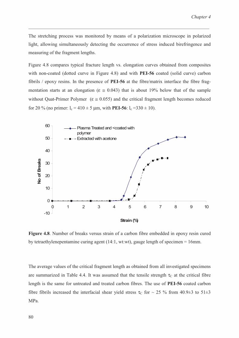
Chapter 4
___________________________________________________________________________
80
The stretching process was monitored by means of a polarization microscope in polarized
light, allowing simultaneously detecting the occurrence of stress induced birefringence and
measuring of the fragment lengths.
Figure 4.8 compares typical fracture length vs. elongation curves obtained from composites
with non-coated (dotted curve in Figure 4.8) and with PEI-56 coated (solid curve) carbon
fibrils / epoxy resins. In the presence of PEI-56 at the fibre/matrix interface the fibre frag-
mentation starts at an elongation (ε ≅ 0.043) that is about 19% below that of the sample
without Quat-Primer Polymer (ε ≅ 0.055) and the critical fragment length becomes reduced
for 20 % (no primer: lc = 410 ± 5 µm, with PEI-56: lc =330 ± 10).
-10
0
10
20
30
40
50
60
0 1 2 3 4 5 6 7 8 9 10
Strain (%)
No
of
Bre
aks
.
Plasma Treated and <coated with
polymer
Extracted with acetone
Figure 4.8. Number of breaks versus strain of a carbon fibre embedded in epoxy resin cured
by tetraethylenepentamine curing agent (14:1, wt:wt), gauge length of specimen = 16mm.
The average values of the critical fragment length as obtained from all investigated specimens
are summarized in Table 4.4. It was assumed that the tensile strength τC at the critical fibre
length is the same for untreated and treated carbon fibres. The use of PEI-56 coated carbon
fibre fibrils increased the interfacial shear yield stress τC for ~ 25 % from 40.9±3 to 51±3
MPa.
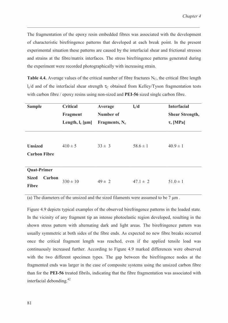
Chapter 4
___________________________________________________________________________
81
The fragmentation of the epoxy resin embedded fibres was associated with the development
of characteristic birefringence patterns that developed at each break point. In the present
experimental situation these patterns are caused by the interfacial shear and frictional stresses
and strains at the fibre/matrix interfaces. The stress birefringence patterns generated during
the experiment were recorded photographically with increasing strain.
Table 4.4. Average values of the critical number of fibre fractures NC, the critical fibre length
lc/d and of the interfacial shear strength τC obtained from Kelley/Tyson fragmentation tests
with carbon fibre / epoxy resins using non-sized and PEI-56 sized single carbon fibre.
Sample Critical
Fragment
Length, lc [�m]
Average
Number of
Fragments, Nc
lc/d Interfacial
Shear Strength,
�, [MPa]
Unsized
Carbon Fibre
410 ± 5 33 ± 3 58.6 ± 1 40.9 ± 1
Quat-Primer
Sized Carbon
Fibre 330 ± 10 49 ± 2 47.1 ± 2 51.0 ± 1
(a) The diameters of the unsized and the sized filaments were assumed to be 7 �m .
Figure 4.9 depicts typical examples of the observed birefringence patterns in the loaded state.
In the vicinity of any fragment tip an intense photoelastic region developed, resulting in the
shown stress pattern with alternating dark and light areas. The birefringence pattern was
usually symmetric at both sides of the fibre ends. As expected no new fibre breaks occurred
once the critical fragment length was reached, even if the applied tensile load was
continuously increased further. According to Figure 4.9 marked differences were observed
with the two different specimen types. The gap between the birefringence nodes at the
fragmented ends was larger in the case of composite systems using the unsized carbon fibre
than for the PEI-56 treated fibrils, indicating that the fibre fragmentation was associated with
interfacial debonding.42

Chapter 4
___________________________________________________________________________
82
a)
b)
Figure 4.9. Optical micrographs of birefringence patterns observed upon stretching of carbon
single fibre / epoxy resin composites to the fragmentation saturation level. a) Unsized, b)
PEI-56 sized carbon fibre composite system.
Conclusions:
The primary and secondary amino groups of poly(ethylene imine) have been functionalized
with quaternary carbonates and various carbonate couplers using mild conditions in an aprotic
solvent. The polymers were successfully characterized with the help of model reaction by
NMR spectroscopy. The hydrodynamic diameter of the functionalized polymers was found to
be smaller compared to unmodified b-PEI. The cationic polymer is suitable for coating
application on oxidized graphitic surfaces and the coating is permanent due to strong
electrostatic force of attraction. The sizing of carbon fibre with epoxy reactive quaternary
primers leads to the improvement in fibre matrix adherence.
References:
1. Bourgeois, P.; Davidson, T. J. Adhes. 1994, 45, 73.
2. Drzal, L. T. Advances in Polymer Science 1986, 75, 1.
3. Zou, Y. L.; Netravali, A. N. J. Adhes. Sci. Technol. 1995, 9, 1505.
0.2 mm
0.25 mm
Chapter 4
___________________________________________________________________________
83
4. Yumitrori, S.; Wang, D.; Jones, F. R. Composites 1994, 25, 698.
5. Pittman, U. C.; Jiang, W.; He, G. R.; Gardner, S. D. Carbon 1998, 36, 25.
6. Morra, M.; Ochiello, E.; Garbassi, F.; Nicolais, L. Compos. Sci. Technol. 1991, 42, 361.
7. Yuan, L. Y.; Chen, C. S.; Shyu, S. S.; Lai, J. Y. Compos. Sci. Technol. 1992, 45, 1.
8. Da, Y.; Wang, D.; Sun, M.; Chen, C.; Yue, J. Compos. Sci. Technol. 1987, 30, 119.
9. Park, S. J.; Kim, M. H. J Mater. Sci. 2000, 35, 1901.
10. Park, S. J.; Park, B. J J Mater. Sci. Lett. 1999, 18, 47.
11. Fjeldy, A.; Olsen, T.; Rysjedal, J. H.; Berg, J. E. Composites Part A 2001, 32, 373.
12. Ramanathan, T.; Bismarck, A.; Schluz, E.; Subramanian, K. Compos. Sci. Technol. 2001,
61, 599.
13. Toyoda, M.; Katoh, H.; Inagaki, M. Carbon 2001, 39, 2231.
14. Drzal, L. T.; Rich, M. J.; Lloyd, P. M. J. Adhes.1982, 16, 1.
15. Drzal, L. T.; Rich, M. J.; Koenig, M. F.; Lloyd, P. M. J. Adhes. 1983, 16, 133.
16. Cooke, T. F. J. Polym. Eng. 1987, 7, 197.
17. Vassoudevane, L. B.; Samuel, I. S. Chem. Mater. 1994, 6, 1880.
18. Yang, D. Q.; Sacher, E. Chem. Mater. 2006, 18, 1811.
19. Chang, H.; Bard, A. J. J. Am. Chem. Soc. 1991, 113, 5588.
20. Chu, X.; Schmidt, L. D. Carbon 1991, 29, 1251.
21. Tracz, A.; Wegner G.; Rabe J. P. Langmuir 1993, 9, 3033.
22. Stabel, A.; Eichhorst, K.; Rabe, J. P.; Gonzalez-Elipe, A. R. Langmuir 1998, 14, 3033.
23. Stabel, A.; Eichhorst, K.; Rabe, J. P.; Gonzalez-Elipe, A. R. Langmuir 1998, 14, 7324.
24. Moeller, M.; Beginn, U.; Keul, H.; Thomas, H. European Patent 2006 EP 1710282 A1
2006 1011.
Chapter 4
___________________________________________________________________________
84
25. Ubaghs, L.; Fricke, N.; Keul, H.; Höcker, H. Macromol. Rapid Commun. 2004, 25, 517.
26. Pasquier, N.; Keul, H.; Moeller, M. Designed Monomers and Polymers 2005, 8, 679.
27. Graham, A.R.; Millidge, A. F.; Young, D. P. J. Chem. Soc. 1954, 2180.
28. R. N. Lee, “Carbon Fiber Surface Properties“ in S. M. Lee (ed.), “International
Encyclopedia of Composites”, Vol. 1, p. 241 – 253, VCH Publishers, New York 1990.
29. Piper, E. L.; Soc. Min. Eng., AIME Preprints 1973, 73, H14.
30. Blakeslee, O. L.; Proctor, D. G.; Seldin, E. J.; Spence, G. B.; Weng, T. J. Appl. Phys.
1970, 41, 3373.
31. Tracz, A.; Wegner, G.; Rabe, J. P. Langmuir 2003, 19, 6807.
32. Peebles, L. H. Carbon Fibres Formation Structures & Properties: Formation, Structure
and Properties, CRC Press Inc., Boca Raton 1994.
33. Riggs, J. P. “Carbon Fibres”, in S. M. Lee (ed.), “International Encyclopedia of
Composites”, 1990, 1, 197 VCH Publishers, New York.
34. Fuli, Z.; Grubb, D. T. J. Mater. Sci. 1984, 29, 189.
35. Wells, J. K.; Beaumont, P. W. R. J. Mater. Sci. 1985, 20, 1275.
36. DiFrancia, C.; Ward, T. C.; Claus, R. O. Composites 1996, 27A, 597.
37. Kelley, A.; Tyson, W. R. J. Mech. Phys. Solids 1965, 13, 329.
38. Scherf, J.; Wagner, H. D. Polym. Eng. Sci. 1992, 32, 298.
39. Melanitis, N.; Galiotis, C.; Tetlow, P. L.; Davies, C. K. L. J. Compos. Mater. 1992, 26,
574.
40. Kim, B. W.; Nairn, J. A. J. Compos. Mater. 2002, 36, 1825.
41. Yavin, B.; Gallis, H. E.; Scherf, J.; Eitan, A.; Wagner, H. D. Polym. Compos. 1991, 12,
436.
42. Huang, Y.; Young, R. J. Composites 1995, 26, 541.
43. Zhou, X. F.; Wagner, H. D.; Nutt, S. R. Composites Part A 2001, 32, 1543.

Chapter 4
___________________________________________________________________________
85
44. Miller, B.; Muri, P.; Rebenfeld, L. Compos. Sci. Technol. 1987, 28, 17.
45.Marshall, D. B. J. Am. Ceram. Soc. 1984, 67, 259.
46. Deng, S.; Ye, L.; Mai, Y. U, Adv. Compos. Mater. 1998, 7, 169.
47. Wu, H. F.; Claypool, C. M. J. Mater. Sci. Lett. 1991, 10, 269.
Chapter 5
___________________________________________________________________________
86
Chapter 5: Intra - and intermolecular self
assembly of branched polyethylenimine on
graphite.
Introduction:
Since Flory’s theoretical report in 1952 on polycondensation of ABf monomers to generate
high branching densities polymer without passing a gel point,1 to date continuous effort in
synthesis, characterization and theory2,3, 4,5
have made possible to deliberately “tune” polymer
architecture.6 This has generated interest in understanding the role of the architecture on the
interfacial properties and offered new possibility for single molecule manipulation and
structure formation. Although hyperbranched polymers do not have perfectly defined
structures, they retain many of the important features of dendritic macromolecules (i.e.,
multiple end groups, high solubility, and reduced viscosities relative to their linear
counterparts).
Polyethylenimines (PEI) represents important class of readily available, highly branched
molecules (cf. Scheme 5.1), water-soluble and widely used in paper industry,7 food
industries,8 cosmetic
9 and pharmaceutical industries.
10,11,12,13,14 b-PEI is also known for its
high capability in forming a number of different complexes with metal ions,15
anionic
polyelectrolytes16,17
and surfactants.18
For instance, complexation of b-PEI with n-alkyl
carboxylic acids results in ionic complexes that self assemble into defined mesophase
structures,19
while in solution the complex lead to unimolecular micelles “nanocapsules”.20
Moreover, b-PEI adsorbs readily on variety of surfaces like muscovite mica, silica21,22
and it
is frequently used as primer coating.23
Schneider et al. studies represent one of the few reports
that addressed the adsorption behaviour of b-PEI form single molecules to continuous
layer.24,25
In particular on hydrophobic graphite surface (HOPG), it has been shown that the
shape and the distance between individual b-PEI chains are controlled by degree of
protonation of the amine groups.
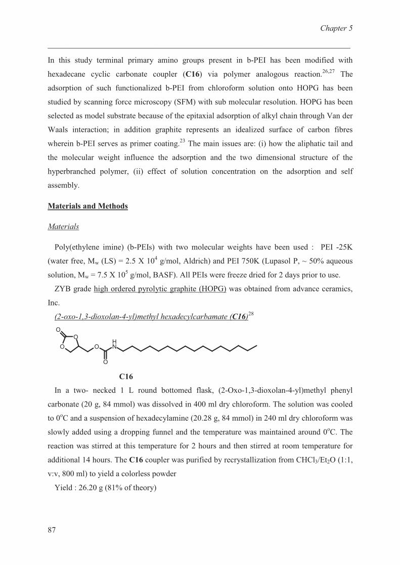
Chapter 5
___________________________________________________________________________
87
In this study terminal primary amino groups present in b-PEI has been modified with
hexadecane cyclic carbonate coupler (C16) via polymer analogous reaction.26,27
The
adsorption of such functionalized b-PEI from chloroform solution onto HOPG has been
studied by scanning force microscopy (SFM) with sub molecular resolution. HOPG has been
selected as model substrate because of the epitaxial adsorption of alkyl chain through Van der
Waals interaction; in addition graphite represents an idealized surface of carbon fibres
wherein b-PEI serves as primer coating.23
The main issues are: (i) how the aliphatic tail and
the molecular weight influence the adsorption and the two dimensional structure of the
hyperbranched polymer, (ii) effect of solution concentration on the adsorption and self
assembly.
Materials and Methods
Materials
Poly(ethylene imine) (b-PEIs) with two molecular weights have been used : PEI -25K
(water free, Mw (LS) = 2.5 X 10⁴ g/mol, Aldrich) and PEI 750K (Lupasol P, ~ 50% aqueous
solution, Mw = 7.5 X 10⁵ g/mol, BASF). All PEIs were freeze dried for 2 days prior to use.
ZYB grade high ordered pyrolytic graphite (HOPG) was obtained from advance ceramics,
Inc.
(2-oxo-1,3-dioxolan-4-yl)methyl hexadecylcarbamate (C16)28
O
O
O
O
O
NH
C16
In a two- necked 1 L round bottomed flask, (2-Oxo-1,3-dioxolan-4-yl)methyl phenyl
carbonate (20 g, 84 mmol) was dissolved in 400 ml dry chloroform. The solution was cooled
to 0oC and a suspension of hexadecylamine (20.28 g, 84 mmol) in 240 ml dry chloroform was
slowly added using a dropping funnel and the temperature was maintained around 0oC. The
reaction was stirred at this temperature for 2 hours and then stirred at room temperature for
additional 14 hours. The C16 coupler was purified by recrystallization from CHCl3/Et2O (1:1,
v:v, 800 ml) to yield a colorless powder
Yield : 26.20 g (81% of theory)
Chapter 5
___________________________________________________________________________
88
1H-NMR(DMSO-d6): � = 0.85 (t, 3H, CH3), 1.10-1.32 (s, 26H, CH2
alkane), 1.30-1.45 (m, 2H,
NHCH2CH2), 2.96 (dt, 2H, NHCH2), 4.10-4.29 (m, 3H, OCOOCHaH
b, NHCOOCH2), 4.55
(dd, 1H, OCOOCHaH
b), 4.93-5.05 (m, 1H, OCH), 7.33 (t, 1H, NH) ppm.
13C-NMR(DMSO-d6): � = 13.9 (CH3), 22.0 (CH2CH3), 26, 28.5-29.2 (12C, CH2
alkane), 31.2
(NHCH2CH2), 40.2 (NHCH2), 62.9 (NHCOOCH2), 65.8 (OCOOCH2), 74.8 (OCH), 154.6
(OCOO), 155.5 (OCONH) ppm.
General Procedure for the functionalization of b-PEI’s with various functional cyclic
carbonates26,27
The polyethylenimine (b-PEI) is a commercial hyperbranched polymer with primary,
secondary and tertiary amine in the molar ratio of 31:39:30 respectively. The primary amino
groups present in b-PEI’s were selectively modified with the functionalized cyclic carbonate
coupler (C16). The secondary and tertiary amino groups remained unmodified. At 50 oC the
respective amounts of cyclic carbonate (cf. Table 5.1) were added to a solution of freeze dried
b-PEI (1.0 g) in 10 ml DMF. After stirring the solution at 50oC for 72 hours the polymer was
precipitated in a 2:1 (vol : vol) mixture of hexane and diethylether. The polymer was re-
dissolved in 10 ml methanol, stirred vigorously for 15 min and re-precipitated in the above
mentioned non-solvent. After repeating the cycle for 3 times the solvent was distilled off and
the product was dried (room temperature, 24 h) at 1.3 Pa to yield a slightly yellow solid.
The absence of characteristic peaks of the cyclic carbonate in 1H-NMR and
13C-NMR
indicates that all the cyclic carbonate has reacted with b- PEI.
In the subsequent text the index of b-PEI indicates its molecular weight in kD, while the
extension C1625 denotes a b-PEI where 25 mole% of the primary amino groups have been
reacted with hexadecyl – carbonate coupler (C16).
Table 5.1. Composition of the polymers after reaction of PEI's with cyclic carbonate coupler.
Polymer b-PEI – 25 KDa
mg
b-PEI – 750 KDa
mg
Coupler C16
mg
Yield
PEI25K-C1625
PEI750K-C1625
1000
----
----
1000
1120
1120
1.6 g, 78 %
1.7 g, 82 %
Chapter 5
___________________________________________________________________________
89
Number average molecular weight for PEI25K-C1625 and PEI750K-C1625 corresponds to 33
KDa and 970 KDa respectively (theoretically calculated from the molecular weight of
unmodified b-PEI).
Measurements
1H- and
13C-NMR spectra were recorded on a Bruker DPX-300 FT-NMR spectrometer at
300 MHz and 75 MHz respectively. Chloroform-d (CDCl3) and dimethylsulfoxide-d6
(DMSO- d6) were used as solvents, and tetramethylsilane (TMS) was used as internal
standard.
The infrared spectra were measured on a Thermo Nicolet Nexus 470 spectrometer with a re-
solution of 4 cm-1
. The samples were prepared as KBr pellets for the measurement in trans-
mission mode.
The hydrodynamic radius of the macromolecules was determined on ALV 5000 dynamic
light scattering system. The concentration of the polymer was 1 – 10 g/L in chloroform
solution. The data was analyzed on ALV correlator software version 3.0. The date was fitted
by using DLS-exponential (g2(t)) fit to obtain the mass average hydrodynamic radii.
The surface morphology of the monofilms was investigated by atomic force microscopy
(AFM) at room temperature using a Nanoscope IIIa. Imaging was done in the tapping mode
using standard silicon cantilevers: Nanoworld Pointprobe NCH 330 or 75 kHz and super-
sharp tips from µ-Masch. The deposition was done by spin coating a volume of 40 �L from
solutions of the polymers, containing 10-3
wt% to 10-4
wt% of polymer in pure chloroform
onto freshly cleaved HOPG at a rotation rate of 2000 rpm. The same samples were also
imaged with Molecular Imaging as it allowed us to investigate single molecules conformation
in different atmosphere. First, the coated substrates were imaged in situ under nitrogen
atmosphere for 2 h. Then the imaging was carried out in situ under atmosphere of water and
ethanol (1:1) for 8 h. Finally, the samples were dried and imaged again under flux of nitrogen.
The molecular weight of the islands was measured from the AFM images using Nanoscope
5.12 r5 software. The function called “particle analyses” was used to estimate the volume of
molecule from the surface area and height of the each island. The volume of the island
multiplied by the Avogadros number (NA) leads to the molecular weight. Thus, molecular
weight distribution diagram is obtained by plotting molecular weight of islands against the
amount of polymer with given molecular weight.

Chapter 5
___________________________________________________________________________
90
The amount of polymer adsorbed (�, mg/m2) onto graphite (from AFM images) was
calculated using “bearing” function in the Nanoscope 5.12 r5 software. The bearing area (%)
of AFM image times the average height of the molecules and density of the polymer leads to
the amount of polymer adsorbed onto graphite.
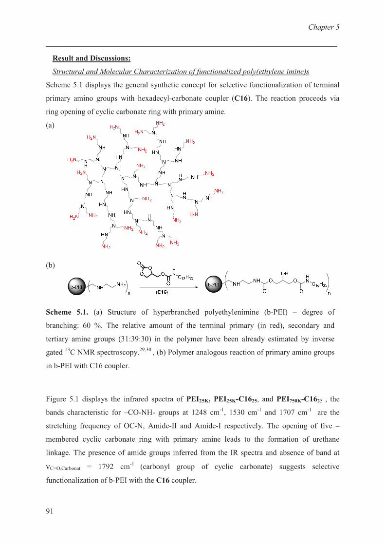
Chapter 5
___________________________________________________________________________
91
Result and Discussions:
Structural and Molecular Characterization of functionalized poly(ethylene imine)s
Scheme 5.1 displays the general synthetic concept for selective functionalization of terminal
primary amino groups with hexadecyl-carbonate coupler (C16). The reaction proceeds via
ring opening of cyclic carbonate ring with primary amine.
(a)
(b)
Scheme 5.1. (a) Structure of hyperbranched polyethylenimine (b-PEI) – degree of
branching: 60 %. The relative amount of the terminal primary (in red), secondary and
tertiary amine groups (31:39:30) in the polymer have been already estimated by inverse
gated 13
C NMR spectroscopy.29,30
, (b) Polymer analogous reaction of primary amino groups
in b-PEI with C16 coupler.
Figure 5.1 displays the infrared spectra of PEI25K, PEI25K-C1625, and PEI750K-C1625 , the
bands characteristic for –CO-NH- groups at 1248 cm-1
, 1530 cm-1
and 1707 cm-1
are the
stretching frequency of OC-N, Amide-II and Amide-I respectively. The opening of five –
membered cyclic carbonate ring with primary amine leads to the formation of urethane
linkage. The presence of amide groups inferred from the IR spectra and absence of band at
νC=O,Carbonat = 1792 cm-1
(carbonyl group of cyclic carbonate) suggests selective
functionalization of b-PEI with the C16 coupler.
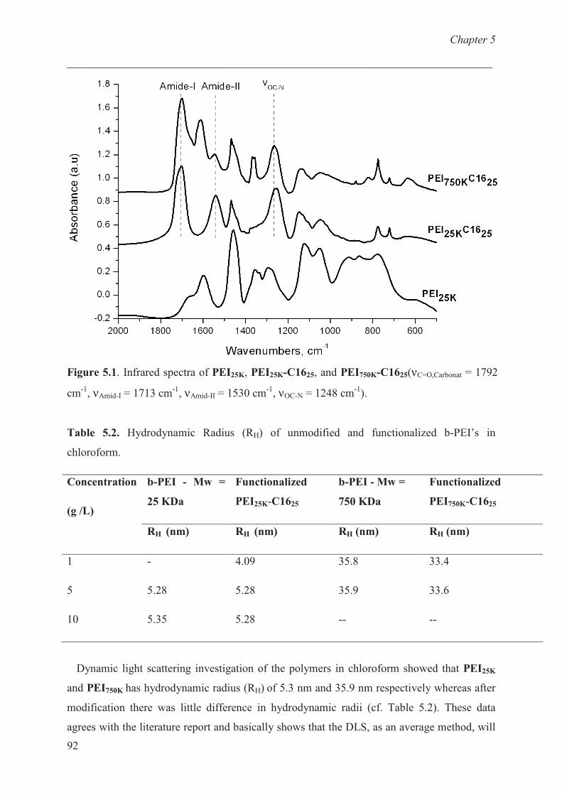
Chapter 5
___________________________________________________________________________
92
Figure 5.1. Infrared spectra of PEI25K, PEI25K-C1625, and PEI750K-C1625(νC=O,Carbonat = 1792
cm-1
, νAmid-I = 1713 cm-1
, νAmid-II = 1530 cm-1
, νOC-N = 1248 cm-1
).
Table 5.2. Hydrodynamic Radius (RH) of unmodified and functionalized b-PEI’s in
chloroform.
b-PEI - Mw =
25 KDa
Functionalized
PEI25K-C1625
b-PEI - Mw =
750 KDa
Functionalized
PEI750K-C1625
Concentration
(g /L)
RH (nm) RH (nm) RH (nm) RH (nm)
1
5
10
-
5.28
5.35
4.09
5.28
5.28
35.8
35.9
--
33.4
33.6
--
Dynamic light scattering investigation of the polymers in chloroform showed that PEI25K
and PEI750K has hydrodynamic radius (RH) of 5.3 nm and 35.9 nm respectively whereas after
modification there was little difference in hydrodynamic radii (cf. Table 5.2). These data
agrees with the literature report and basically shows that the DLS, as an average method, will
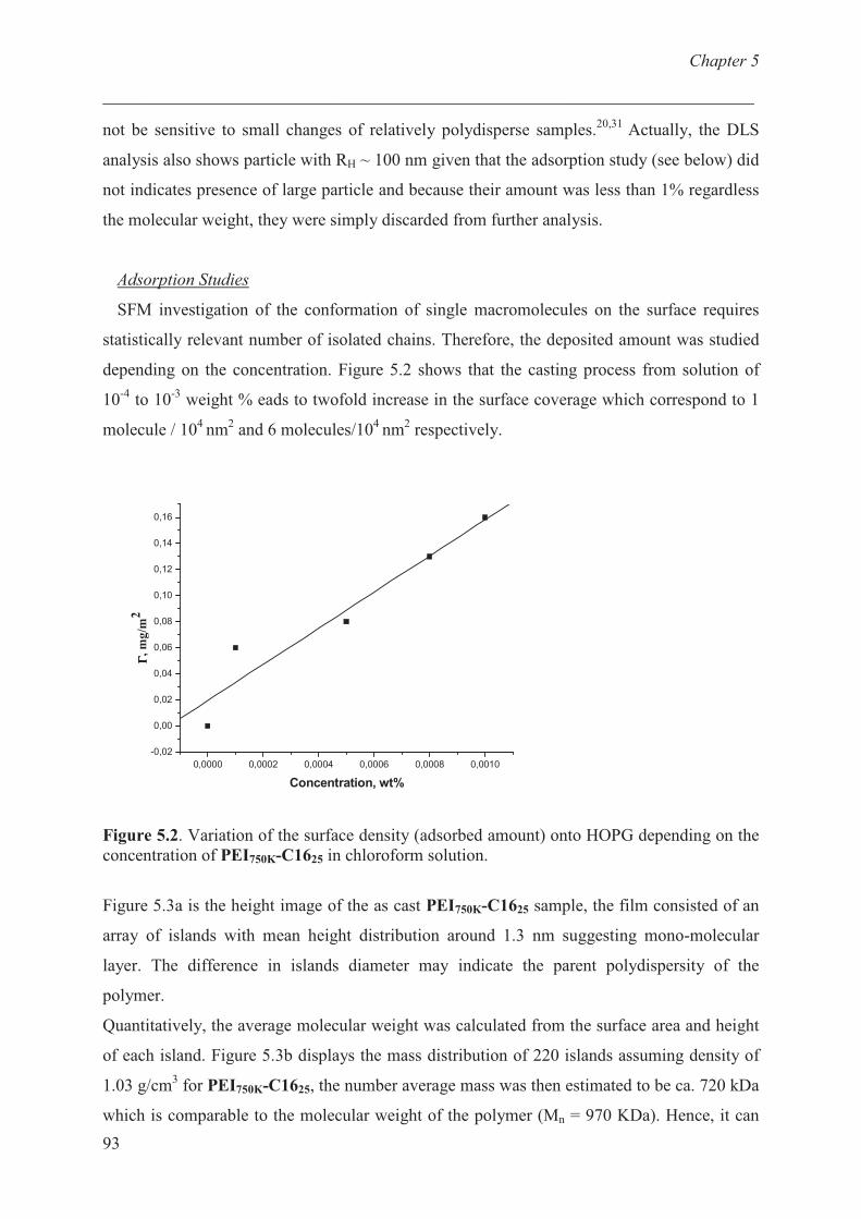
Chapter 5
___________________________________________________________________________
93
not be sensitive to small changes of relatively polydisperse samples.20,31
Actually, the DLS
analysis also shows particle with RH ~ 100 nm given that the adsorption study (see below) did
not indicates presence of large particle and because their amount was less than 1% regardless
the molecular weight, they were simply discarded from further analysis.
Adsorption Studies
SFM investigation of the conformation of single macromolecules on the surface requires
statistically relevant number of isolated chains. Therefore, the deposited amount was studied
depending on the concentration. Figure 5.2 shows that the casting process from solution of
10-4
to 10-3
weight % eads to twofold increase in the surface coverage which correspond to 1
molecule / 104
nm2 and 6 molecules/10
4 nm
2 respectively.
0,0000 0,0002 0,0004 0,0006 0,0008 0,0010
-0,02
0,00
0,02
0,04
0,06
0,08
0,10
0,12
0,14
0,16
ΓΓ ΓΓ,
mg
/m2
Concentration, wt%
Figure 5.2. Variation of the surface density (adsorbed amount) onto HOPG depending on the
concentration of PEI750K-C1625 in chloroform solution.
Figure 5.3a is the height image of the as cast PEI750K-C1625 sample, the film consisted of an
array of islands with mean height distribution around 1.3 nm suggesting mono-molecular
layer. The difference in islands diameter may indicate the parent polydispersity of the
polymer.
Quantitatively, the average molecular weight was calculated from the surface area and height
of each island. Figure 5.3b displays the mass distribution of 220 islands assuming density of
1.03 g/cm3 for PEI750K-C1625, the number average mass was then estimated to be ca. 720 kDa
which is comparable to the molecular weight of the polymer (Mn = 970 KDa). Hence, it can
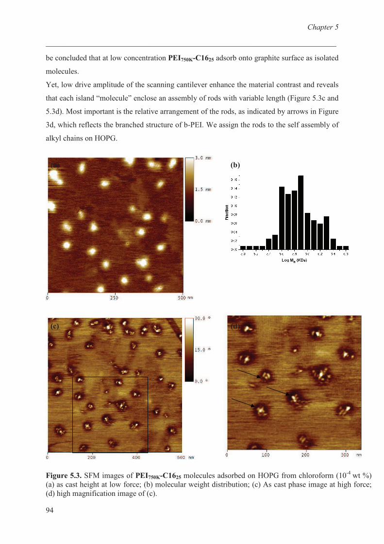
Chapter 5
___________________________________________________________________________
94
be concluded that at low concentration PEI750K-C1625 adsorb onto graphite surface as isolated
molecules.
Yet, low drive amplitude of the scanning cantilever enhance the material contrast and reveals
that each island “molecule” enclose an assembly of rods with variable length (Figure 5.3c and
5.3d). Most important is the relative arrangement of the rods, as indicated by arrows in Figure
3d, which reflects the branched structure of b-PEI. We assign the rods to the self assembly of
alkyl chains on HOPG.
Figure 5.3. SFM images of PEI750K-C1625 molecules adsorbed on HOPG from chloroform (10-4
wt %)
(a) as cast height at low force; (b) molecular weight distribution; (c) As cast phase image at high force;
(d) high magnification image of (c).
(a) (b)
(c) (d)
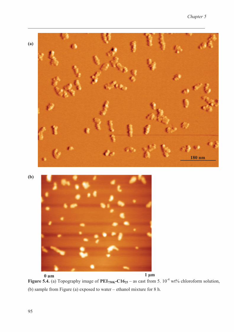
Chapter 5
___________________________________________________________________________
95
(a)
(b)
Figure 5.4. (a) Topography image of PEI750K-C1625 – as cast from 5. 10-4
wt% chloroform solution,
(b) sample from Figure (a) exposed to water – ethanol mixture for 8 h.
0 �m 1 �m
180 nm
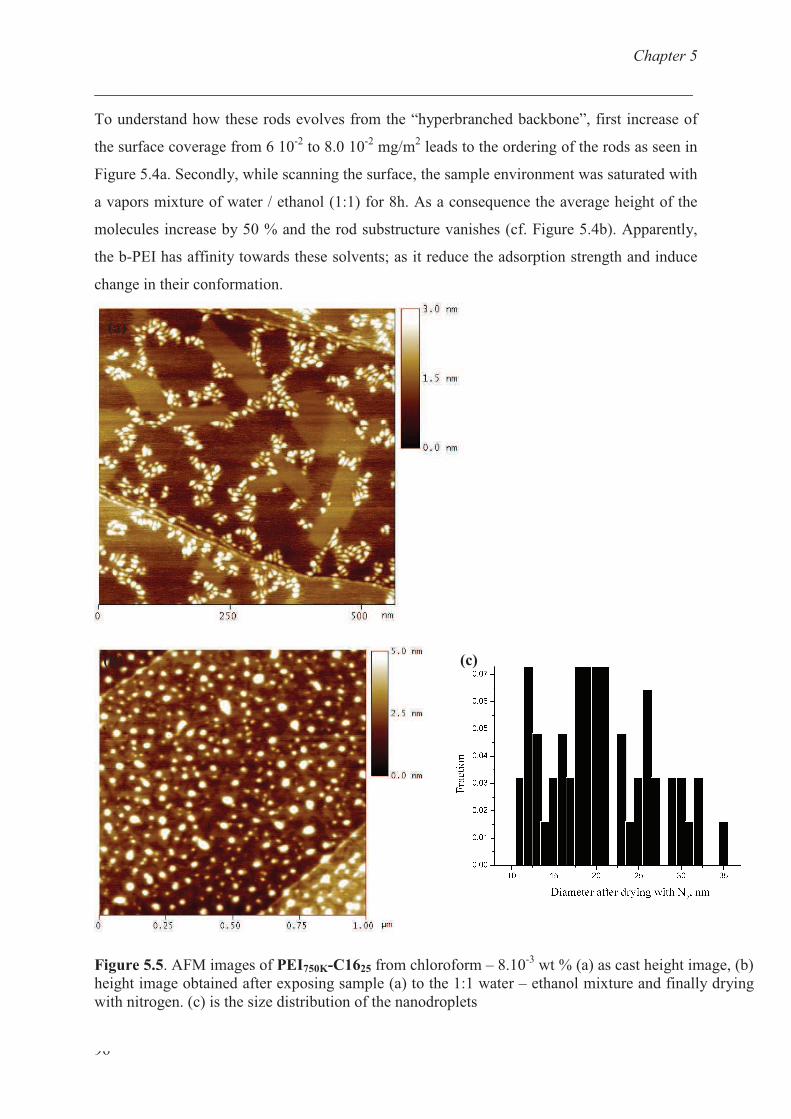
Chapter 5
___________________________________________________________________________
96
To understand how these rods evolves from the “hyperbranched backbone”, first increase of
the surface coverage from 6 10-2
to 8.0 10-2
mg/m2 leads to the ordering of the rods as seen in
Figure 5.4a. Secondly, while scanning the surface, the sample environment was saturated with
a vapors mixture of water / ethanol (1:1) for 8h. As a consequence the average height of the
molecules increase by 50 % and the rod substructure vanishes (cf. Figure 5.4b). Apparently,
the b-PEI has affinity towards these solvents; as it reduce the adsorption strength and induce
change in their conformation.
Figure 5.5. AFM images of PEI750K-C1625 from chloroform – 8.10-3
wt % (a) as cast height image, (b)
height image obtained after exposing sample (a) to the 1:1 water – ethanol mixture and finally drying
with nitrogen. (c) is the size distribution of the nanodroplets
(b) (c)
(a)
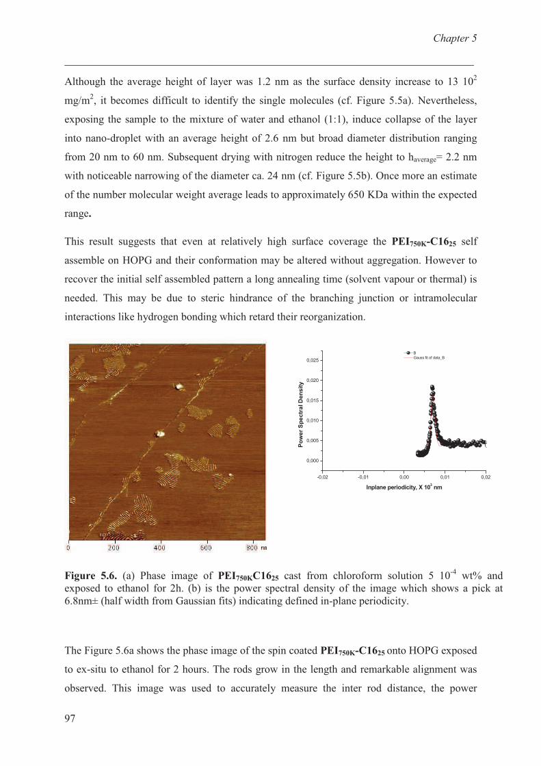
Chapter 5
___________________________________________________________________________
97
Although the average height of layer was 1.2 nm as the surface density increase to 13 102
mg/m2, it becomes difficult to identify the single molecules (cf. Figure 5.5a). Nevertheless,
exposing the sample to the mixture of water and ethanol (1:1), induce collapse of the layer
into nano-droplet with an average height of 2.6 nm but broad diameter distribution ranging
from 20 nm to 60 nm. Subsequent drying with nitrogen reduce the height to haverage= 2.2 nm
with noticeable narrowing of the diameter ca. 24 nm (cf. Figure 5.5b). Once more an estimate
of the number molecular weight average leads to approximately 650 KDa within the expected
range.
This result suggests that even at relatively high surface coverage the PEI750K-C1625 self
assemble on HOPG and their conformation may be altered without aggregation. However to
recover the initial self assembled pattern a long annealing time (solvent vapour or thermal) is
needed. This may be due to steric hindrance of the branching junction or intramolecular
interactions like hydrogen bonding which retard their reorganization.
-0,02 -0,01 0,00 0,01 0,02
0,000
0,005
0,010
0,015
0,020
0,025
B
Gauss fit of data_B
Po
wer
Sp
ectr
al D
en
sit
y
Inplane periodicity, X 103 nm
Figure 5.6. (a) Phase image of PEI750KC1625 cast from chloroform solution 5 10-4
wt% and
exposed to ethanol for 2h. (b) is the power spectral density of the image which shows a pick at
6.8nm± (half width from Gaussian fits) indicating defined in-plane periodicity.
The Figure 5.6a shows the phase image of the spin coated PEI750K-C1625 onto HOPG exposed
to ex-situ to ethanol for 2 hours. The rods grow in the length and remarkable alignment was
observed. This image was used to accurately measure the inter rod distance, the power
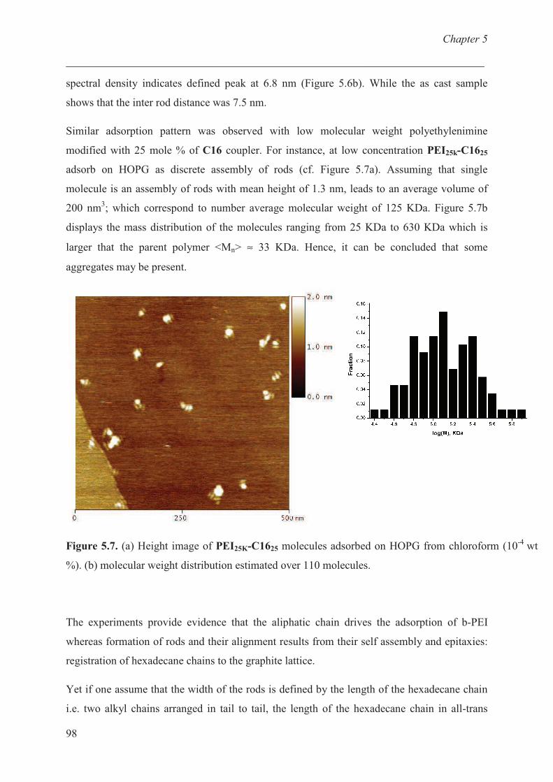
Chapter 5
___________________________________________________________________________
98
spectral density indicates defined peak at 6.8 nm (Figure 5.6b). While the as cast sample
shows that the inter rod distance was 7.5 nm.
Similar adsorption pattern was observed with low molecular weight polyethylenimine
modified with 25 mole % of C16 coupler. For instance, at low concentration PEI25k-C1625
adsorb on HOPG as discrete assembly of rods (cf. Figure 5.7a). Assuming that single
molecule is an assembly of rods with mean height of 1.3 nm, leads to an average volume of
200 nm3; which correspond to number average molecular weight of 125 KDa. Figure 5.7b
displays the mass distribution of the molecules ranging from 25 KDa to 630 KDa which is
larger that the parent polymer <Mn> ≈ 33 KDa. Hence, it can be concluded that some
aggregates may be present.
Figure 5.7. (a) Height image of PEI25K-C1625 molecules adsorbed on HOPG from chloroform (10-4
wt
%). (b) molecular weight distribution estimated over 110 molecules.
The experiments provide evidence that the aliphatic chain drives the adsorption of b-PEI
whereas formation of rods and their alignment results from their self assembly and epitaxies:
registration of hexadecane chains to the graphite lattice.
Yet if one assume that the width of the rods is defined by the length of the hexadecane chain
i.e. two alkyl chains arranged in tail to tail, the length of the hexadecane chain in all-trans
Chapter 5
___________________________________________________________________________
99
conformation is 2.2nm, will leads to 4.4nm. It is less than the inter-rods distance 6.8nm but it
reflects the steric hindrance that arises from the branched polymer backbone and their
terminal groups to which the aliphatic tails are anchored. It has been shown that in the bulk
the branched topology of the PEI polymer does not prevent self assembly of the alkyl chain
but rather reduce their ordering and crystallinity within the layered structure32
.
Perfect dendrimer has degree of branching of 100% while b-PEI is 60%29,30
which are
distributed within a Gaussian sphere with hydrodynamic diameter of 70nm20
. Upon
adsorption, the conformation of the molecules will result from the interplay between the
polymer substrate interactions: i) spreading increase the contact area monomers/substrate and
ii) long range van der Waals interaction may be repulsive or attractive all depends on the sign
of the Hamaker, and iii) the elastic cost due to the intramolecular interactions. Their relative
magnitude depends on the system in consideration.
That leads to the model depicted in Figure 5.8 which correlates the single chain conformation
to the surface density.
Conclusions:
In good solvent chloroform the modification of the terminal groups of the b-PEI with
hexadecane chains does not influence their hydrodynamic radius RH = 35nm.
Upon deposition on HOPG their conformation is controlled by surface coverage and by the
two dimensional self-assembly of the “stickers” aliphatic chains. At low surface density, the
alkyl chain organize within single macromolecules which turn it reduce the overall contact
area by 50% relative to their size in chloroform.
Close to the monolayer coverage highly ordered structure evolves with characteristic distance
controlled by the length of the hexadecane chains and the steric hindrance of the branched
backbone.
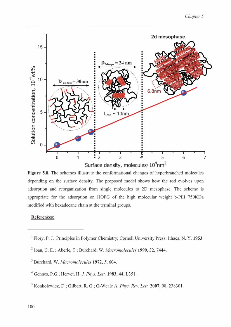
Chapter 5
___________________________________________________________________________
100
Figure 5.8. The schemes illustrate the conformational changes of hyperbranched molecules
depending on the surface density. The proposed model shows how the rod evolves upon
adsorption and reorganization from single molecules to 2D mesophase. The scheme is
appropriate for the adsorption on HOPG of the high molecular weight b-PEI 750KDa
modified with hexadecane chain at the terminal groups.
References:
1 Flory, P. J. Principles in Polymer Chemistry; Cornell University Press: Ithaca, N. Y. 1953.
2 Ioan, C. E. ; Aberle, T.; Burchard, W. Macromolecules 1999, 32, 7444.
3 Burchard, W. Macromolecules 1972, 5, 604.
4 Gennes, P.G.; Hervet, H. J. Phys. Lett. 1983, 44, L351.
5 Konkolewicz, D.; Gilbert, R. G.; G-Weale A. Phys. Rev. Lett. 2007, 98, 238301.
0
5
10
15
� � � � � � � �
�� ����������������������������
��������������� �������������
D as cast = 30nm
Lrod ~ 10nm
D2d-equ = 24 nm
6.8nm
2d mesophase
Chapter 5
___________________________________________________________________________
101
6 Prokhorova, S. A.; Sheiko, S. S.; Mourran, A.; Azumi, R.; Beginn, U.; Zipp, G.; Ahn, C-
H.; Holerca, M. N.; Percec, V.; Möller, M. Langmuir 2000, 16, 6862.
7 Alince, B.; Vanerek, A.; vandeVen, T. G. M. Ber. Bunsen-Ges. 1996, 100, 954.
8 Evers, O. A.; Fleer, G. J.; Scheutjens, J.; Lyklema, J. J. Colloid Interface Sci. 1986, 111,
446.
9 D’Souza, S. F.; Kamath, N. Appl. Microbiol. Biotechnol. 1988, 29, 136.
10 Boussif, O.; Lezoualc’h, F.; Zanta, M. A.; Mergny, M. D.; Scherman, D.; Demeneix, B.;
Behr, J. P. Proc. Natl. Acad. Sci. USA 1995, 92, 7297-7301.
11 Kircheis, R.; Wightman, L.; Wagner, E. Adv. Drug Delivery Rev. 2001, 53, 341-358.
12 Wu, D.; Liu, Y.; Jiang, X.; Chen, L.; He, C.; Goh, S. H.; Leong, K. W.
Biomacromolecules 2005, 6, 3166-3173.
13 Nichol, C. A.; Yang, D.; Humphrey, W.; Ilgan, S.; Tansey, W.; Higuchi, T.; Zareneyrizi,
F.; Wallace, S.; Podoloff, D. A. Drug Delivery 1999, 6, 187.
14 Hellweg, T.; Henry-Toulme, N.; Chambon, M.; Roux, D. Colloids Surf. A 2000, 163, 71.
15 Bekturov, E. A.; Mamutbekov, G. K. Macromol. Chem. Phys. 1997, 198, 81.
16 Kramer, G.; Buchhammer, H. M.; Lunkwitz, K. Colloids Surf. A 1998, 137, 45.
17 Dissing, U.; Mattiasson, B. J. Biotechnol. 1996, 52, 1.
18 Stroeve, P.; Os, M.; Kunz, R.; Rabolt, J. F. Thin Solid Films 1996, 284−285, 200.
19 Thünemann, A. F.; General, S. Langmuir 2000, 16, 9634.
20 L. Antonietti, C. Aymonier, U. Schlotterbeck, V.M. Garamus, T. Maksimova, W.
Richtering, and S. Mecking Macromolecules, 2005, 38 (14), pp 5914–5920
21 Claesson, P. M.; Paulson, O. E. H.; Blomberg, E.; Burns, N. L. Colloids Surf. A 1997,
123−124, 341.
22 Poptoshev, E.; Rutland, M. W.; Claesson, P. M. Langmuir 2002, 18, 2590.
Chapter 5
___________________________________________________________________________
102
23 Goel, V.; Beginn, U.; Mourran, A.; Möller, M. Macromolecules 2008, 41, 8187.
24 Schneider, M.; Brinkmann, M.; Moehwald, H. Macromolecules 2003, 36, 9510.
25 Pfau, A.; Schrepp, W.; Horn, D. Langmuir, 1999, 15, 3219.
26 Pasquier, N.; Keul, H.; Moeller, M. Designed Monomers and Polymers 2005, 8, 679.
27 Moeller, M.; Beginn, U.; Keul, H.; Thomas, H. European Patent 2006.
28 Pasquier, N.; Keul, H.; Heine, E.; Moeller, M. Biomacromolecules 2007, 8, 2874.
29 Pierre, T. S.; Geckle, M. Macromol. Sci. Chem. 1985, A22, 877.
30 Lukovin, G. M.; Pshezhetsky, V. S.; Murtazaeva, G. A. Eur. Polym. J. 1973, 9, 559.
31 Yu, C.; Zhong, S.; Holger, F.; Julia, P. P.; Salah-Eddine, S. ChemComm 2005, 755, 755.
32 Chen, H.L.; Hsiao, M. S. Macromolecules 1999,32, 2967.
Chapter 6
___________________________________________________________________________
102
Chapter 6: Adsorption behaviour of functionalized
branched polyethylenimine onto graphite : Effect of
charge and alkyl chain.
Introduction
Highly branched polymers like hyperbranched polyethylenimine (b-PEI) have gained
widespread attention due their unique properties, which differ significantly from their linear
counterparts e.g. the large number of terminal functional groups, the intrinsic globular
structure and possibility to accumulate small molecules within the macromolecule. Compared
to dendrimers hyperbranched macromolecules are characterized by lower degree of branching,
but definitely possess non-linear architecture and a high number of reactive end groups.
Adsorption of charged polymers i.e. polyelectrolytes on surfaces and interfaces has been under
extensive theoretical and experimental study for the last four decades.1,2
The adsorption of the
weak polyeletrolyte b-PEI from diluted polymer solutions of all pH values onto high ordered
pyrolytic graphite surfaces (HOPG) has been studied. It was found that single molecules of b-
PEI are adsorbed on hydrophobic and uncharged graphite depending on the pH of the
solution.3 Recently investigation on complexes of b-PEI and n-alkanoic acids with lamellar
mesophorous structures has been reported.4 The long period of the complex bulk structure and
the tendency of the tail chains to crystallize were found to depend on the tail length of the
physically bound n-alkanoic acids. It is well known that molecules containing long alkyl
chain can self assemble on suitable surfaces like graphite, giving rise to highly ordered
structures.5 The interaction of polyelectrolyte complexes is of fundamental interest in wetting
and adhesion.6 The adsorption of macromolecules at the interface generally affects the
conformation of the polymers. The size distribution of polymers in solutions and adsorbed on
the surfaces can be very different.7 Optical reflectometer studies on the adsorption
characteristics of polymers containing different PEO/charge ratios along their backbones on
silica as the substrate revealed the degree of adsorption increases with the increase in charge
density of the polymer. 8
In most published studies the adsorption and distribution of the polymer over the substrate
was estimated by means of macroscopically averaging methods such as optical reflection,
scattering techniques or quartz crystal microbalance (QCM) studies. In contrast, scanning
probe techniques offers the unique possibility to look at the adsorption on nano-meter scale.

Chapter 6
___________________________________________________________________________
103
SFM provides the opportunity for direct observation or visualization of polymers on atomic
flat substrates with sub-molecular resolution. In this work the behaviour of b-PEI modified
with different ratios of alkyl chains and quaternary ammonium groups along the backbone
upon adsorption on highly oriented pyrolytic graphite (HOPG) is studied by means of
scanning force microscopy (SFM). The functionalized polymers were prepared by polymer
analogous reaction between b-PEI and different functionalized carbonate modifiers.9,10,11
The
synthesis of most of the functional carbonates starts from (2-oxo-1,3-dioxolan-4-yl)methyl
phenyl carbonate and the corresponding amines (Scheme 6.1)12
. One or two desired
functionalities were introduced in b-PEI by one step addition of primary amine groups with
functional cyclic carbonates.
Scheme 6.1. Synthesis of functional cyclic carbonates.
Furthermore, the application of one of the polymers as a primer in carbon fibre – epoxy resin
matrix system is investigated. Due to poor wetting of non polar carbon fibres in the epoxy
matrix, interfacial adhesion is poor. Therefore, it would be profitable to pre-coat the carbon
fibre surface with a thin chemically active protective polymer layer that guarantees cohesive
adhesion between the fibre and the matrix. This interfacial polymeric layer would provide
sufficient mobility for the chains to deform under load and therefore retain polymer and
interphase toughness.
This chapter deescribes the adsorption behaviour of b-PEI modified with different cation/alkyl
chain ratios on graphite as a model system for carbon fibres. Subsequently the interfacial shear
strength of the primer modified carbon fibres embedded in epoxy resins are investigated by
means of the well known Kelley - Tyson Fragmentation Test.13
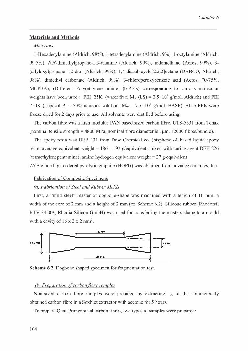
Chapter 6
___________________________________________________________________________
104
Materials and Methods
Materials
1-Hexadecylamine (Aldrich, 98%), 1-tetradecylamine (Aldrich, 9%), 1-octylamine (Aldrich,
99.5%), N,N-dimethylpropane-1,3-diamine (Aldrich, 99%), iodomethane (Acros, 99%), 3-
(allyloxy)propane-1,2-diol (Aldrich, 99%), 1,4-diazabicyclo[2.2.2]octane (DABCO, Aldrich,
98%), dimethyl carbonate (Aldrich, 99%), 3-chloroperoxybenzoic acid (Acros, 70-75%,
MCPBA), (Different Poly(ethylene imine) (b-PEIs) corresponding to various molecular
weights have been used : PEI 25K (water free, Mw (LS) = 2.5 .104 g/mol, Aldrich) and PEI
750K (Lupasol P, ~ 50% aqueous solution, Mw = 7.5 .105 g/mol, BASF). All b-PEIs were
freeze dried for 2 days prior to use. All solvents were distilled before using.
The carbon fibre was a high modulus PAN based sized carbon fibre, UTS-5631 from Tenax
(nominal tensile strength = 4800 MPa, nominal fibre diameter is 7�m, 12000 fibres/bundle).
The epoxy resin was DER 331 from Dow Chemical co. (bisphenol-A based liquid epoxy
resin, average equivalent weight = 186 – 192 g/equivalent, mixed with curing agent DEH 226
(tetraethylenepentamine), amine hydrogen equivalent weight = 27 g/equivalent
ZYB grade high ordered pyrolytic graphite (HOPG) was obtained from advance ceramics, Inc.
Fabrication of Composite Specimens
(a) Fabrication of Steel and Rubber Molds
First, a “mild steel” master of dogbone-shape was machined with a length of 16 mm, a
width of the core of 2 mm and a height of 2 mm (cf. Scheme 6.2). Silicone rubber (Rhodorsil
RTV 3450A, Rhodia Silicon GmbH) was used for transferring the masters shape to a mould
with a cavity of 16 x 2 x 2 mm3.
Scheme 6.2. Dogbone shaped specimen for fragmentation test.
(b) Preparation of carbon fibre samples
Non-sized carbon fibre samples were prepared by extracting 1g of the commercially
obtained carbon fibre in a Soxhlet extractor with acetone for 5 hours.
To prepare Quat-Primer sized carbon fibres, two types of samples were prepared:
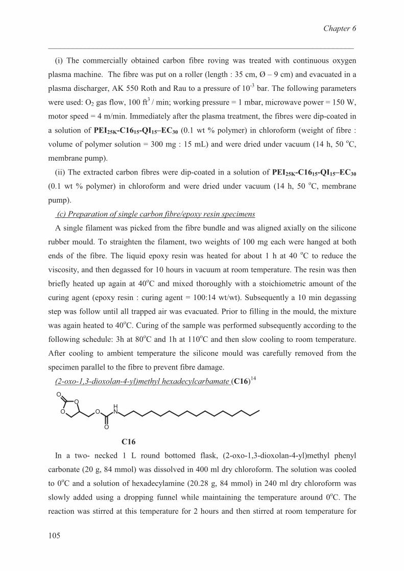
Chapter 6
___________________________________________________________________________
105
(i) The commercially obtained carbon fibre roving was treated with continuous oxygen
plasma machine. The fibre was put on a roller (length : 35 cm, Ø – 9 cm) and evacuated in a
plasma discharger, AK 550 Roth and Rau to a pressure of 10-3
bar. The following parameters
were used: O2 gas flow, 100 ft3
/ min; working pressure = 1 mbar, microwave power = 150 W,
motor speed = 4 m/min. Immediately after the plasma treatment, the fibres were dip-coated in
a solution of PEI25K-C1615-QI15–EC30 (0.1 wt % polymer) in chloroform (weight of fibre :
volume of polymer solution = 300 mg : 15 mL) and were dried under vacuum (14 h, 50 oC,
membrane pump).
(ii) The extracted carbon fibres were dip-coated in a solution of PEI25K-C1615-QI15–EC30
(0.1 wt % polymer) in chloroform and were dried under vacuum (14 h, 50 oC, membrane
pump).
(c) Preparation of single carbon fibre/epoxy resin specimens
A single filament was picked from the fibre bundle and was aligned axially on the silicone
rubber mould. To straighten the filament, two weights of 100 mg each were hanged at both
ends of the fibre. The liquid epoxy resin was heated for about 1 h at 40 oC to reduce the
viscosity, and then degassed for 10 hours in vacuum at room temperature. The resin was then
briefly heated up again at 40oC and mixed thoroughly with a stoichiometric amount of the
curing agent (epoxy resin : curing agent = 100:14 wt/wt). Subsequently a 10 min degassing
step was follow until all trapped air was evacuated. Prior to filling in the mould, the mixture
was again heated to 40oC. Curing of the sample was performed subsequently according to the
following schedule: 3h at 80oC and 1h at 110
oC and then slow cooling to room temperature.
After cooling to ambient temperature the silicone mould was carefully removed from the
specimen parallel to the fibre to prevent fibre damage.
(2-oxo-1,3-dioxolan-4-yl)methyl hexadecylcarbamate (C16)14
O
O
O
O
O
NH
C16
In a two- necked 1 L round bottomed flask, (2-oxo-1,3-dioxolan-4-yl)methyl phenyl
carbonate (20 g, 84 mmol) was dissolved in 400 ml dry chloroform. The solution was cooled
to 0oC and a solution of hexadecylamine (20.28 g, 84 mmol) in 240 ml dry chloroform was
slowly added using a dropping funnel while maintaining the temperature around 0oC. The
reaction was stirred at this temperature for 2 hours and then stirred at room temperature for
Chapter 6
___________________________________________________________________________
106
additional 14 hours. The C16 coupler was purified by recrystallization from CHCl3/Et2O (1:1,
v:v, 800 ml) to yield a colourless powder
Yield: 26.20 g (81% of theory)
1H-NMR(DMSO-d6): � = 0.85 (t, 3H, CH3), 1.10-1.32 (s, 26H, CH2
alkane), 1.30-1.45 (m, 2H,
NHCH2CH2), 2.96 (dt, 2H, NHCH2), 4.10-4.29 (m, 3H, OCOOCHaH
b, NHCOOCH2), 4.55
(dd, 1H, OCOOCHaH
b), 4.93-5.05 (m, 1H, OCH), 7.33 (t, 1H, NH) ppm.
13C-NMR(DMSO-d6): � = 13.9 (CH3), 22.0 (CH2CH3), 26, 28.5-29.2 (12C, CH2
alkane), 31.2
(NHCH2CH2), 40.2 (NHCH2), 62.9 (NHCOOCH2), 65.8 (OCOOCH2), 74.8 (OCH), 154.6
(OCOO), 155.5 (OCONH) ppm.
(2-Oxo-1,3-dioxolan-4-yl)methyl tetradecylcarbamate (C14)14
In a two- necked 1 L round bottomed flask, (2-oxo-1,3-dioxolan-4-yl)methyl phenyl carbonate
(20 g, 84 mmol) was dissolved in 400 ml dry THF. The solution was cooled to 0 oC and a
suspension of tetradecylamine (17.92 g, 84.01 mmol) in 230 ml dry THF was slowly added
using a dropping funnel while maintaining the temperature around 0oC. The reaction was
stirred at this temperature for 2 hours and then stirred at room temperature for additional 14
hours. Solvents were removed by distillation (~20 mbar, 40 °C). The cyclic carbonate C14
was purified by recrystallization from CHCl3/Et2O (7:3, v:v, 100 mL) to yield a colourless
powder.
Yield: 21.1 g, (72 % of theory).
1H NMR (DMSO-d6): � = 0.86 (t, 3H, CH3), 1.10-1.32 (s, 22H, CH2
alkane), 1.30-1.45 (m, 2H,
NHCH2CH2), 2.96 (dt, 2H, NHCH2), 4.10-4.29 (m, 3H, OCOOCHaH
b, NHCOOCH2), 4.55
(dd, 1H, OCOOCHaH
b), 4.93-5.05 (m, 1H, OCH), 7.33 (t, 1H, NH) ppm.
13C NMR (DMSO-d6): � = 13.8 (CH3), 22.0 (CH2CH3), 26.2, 28.7-29.2 (10C, CH2
alkane),
31.2 (NHCH2CH2), 40.3 (NHCH2), 62.9 (NHCOOCH2), 65.8 (OCOOCH2), 74.8 (OCH),
154.6 (OCOO), 155.5 (OCONH) ppm.
(2-Oxo-1,3-dioxolan-4-ylmethyl) octylcarbamate (C8)14
To a solution of (2-oxo-1,3-dioxolan-4-yl)methyl phenyl carbonate (20.0 g, 84.0 mmol) in
200 ml THF at 0°C was added a solution of octylamine (10.9 g, 84.0 mmol) in 100 ml THF
and while maintaining the temperature below 5 °C. The reaction was stirred for 16 h at room
temperature. Solvents were removed by distillation (~20 mbar, 40 °C). The cyclic carbonate
C8 was purified by recrystallization from warm Et2O/CHCl3 (5:1, v:v, 180 mL) to yield a
colourless powder
Yield: 20 g, (85 % of theory).
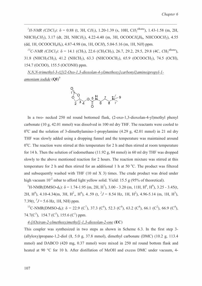
Chapter 6
___________________________________________________________________________
107
1H-NMR (CDCl3): � = 0.88 (t, 3H, CH3), 1.20-1.39 (s, 10H, CH2
alkane), 1.43-1.58 (m, 2H,
NHCH2CH2), 3.17 (dt, 2H, NHCH2), 4.22-4.40 (m, 3H, OCOOCHaHb, NHCOOCH2), 4.55
(dd, 1H, OCOOCHaHb), 4.87-4.98 (m, 1H, OCH), 5.04-5.16 (m, 1H, NH) ppm.
13C-NMR (CDCl3): � = 14.1 (CH3), 22.6 (CH2CH3), 26.7, 29.2, 29.5, 29.8 (4C, CH2
alkane),
31.8 (NHCH2CH2), 41.2 (NHCH2), 63.3 (NHCOOCH2), 65.9 (OCOOCH2), 74.5 (OCH),
154.7 (OCOO), 155.5 (OCONH) ppm.
N,N,N-trimethyl-3-({[(2-Oxo-1,3-dioxolan-4-yl)methoxy]carbonyl}amino)propyl-1-
amonium iodide (QI)9
In a two- necked 250 ml round bottomed flask, (2-oxo-1,3-dioxolan-4-yl)methyl phenyl
carbonate (10 g, 42.01 mmol) was dissolved in 100 ml dry THF. The reactants were cooled to
0oC and the solution of 3-dimethylamino-1-propylamine (4.29 g, 42.01 mmol) in 21 ml dry
THF was slowly added using a dropping funnel and the temperature was maintained around
0oC. The reaction were stirred at this temperature for 2 h and then stirred at room temperature
for 14 h. Then the solution of iodomethane (11.92 g, 84 mmol) in 60 ml dry THF was dropped
slowly to the above mentioned reaction for 2 hours. The reaction mixture was stirred at this
temperature for 2 h and then stirred for an additional 1 h at 50 oC. The product was filtered
and subsequently washed with THF (10 ml X 3) times. The crude product was dried under
high vacuum 10-2
mbar to afford light yellow solid. Yield: 15.5 g (95% of theoretical).
1H-NMR(DMSO-d6): � = 1.74-1.95 (m, 2H, H
7), 3.00 - 3.20 (m, 11H, H
6, H
9), 3.25 - 3.45(t,
2H, H8), 4.10-4.34(m, 3H, H
2,, H
4), 4..59 (t,
2J = 8.54 Hz, 1H, H
2), 4.96-5.14 (m, 1H, H
3),
7.39(t, 3J = 5.6 Hz, 1H, NH) ppm.
13C-NMR(DMSO-d6): � = 22.9 (C
7), 37.3 (C
6), 52.3 (C
9), 63.2 (C
8), 66.1 (C
2), 66.9 (C
4),
74.7(C3), 154.7 (C
5), 155.6 (C
1) ppm.
4-[(Oxiran-2-ylmethoxy)methyl]-1,3-dioxolan-2-one (EC)
This coupler was synthesized in two steps as shown in Scheme 6.3. In the first step 3-
(allyloxy)propane-1,2-diol (1, 5.0 g, 37.8 mmol), dimethyl carbonate (DMC) (10.2 g, 113.4
mmol) and DABCO (420 mg, 0.37 mmol) were mixed in 250 ml round bottom flask and
heated at 90 °C for 10 h. After distillation of MeOH and excess DMC under vacuum, 4-
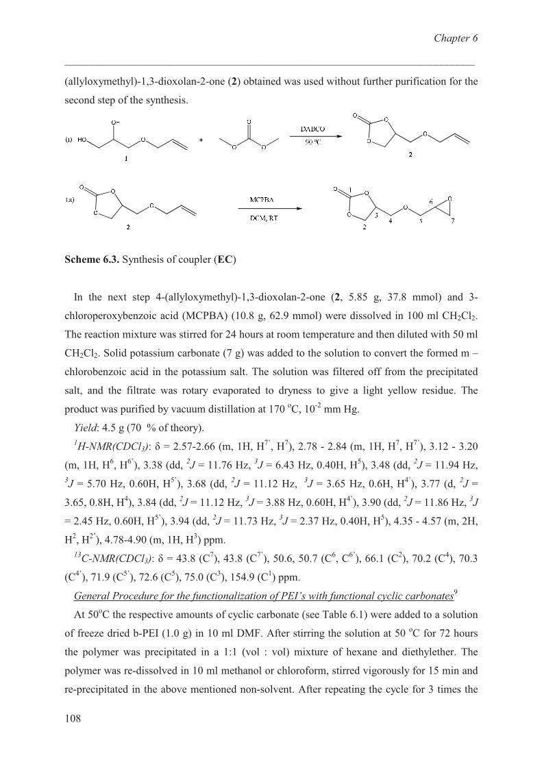
Chapter 6
___________________________________________________________________________
108
(allyloxymethyl)-1,3-dioxolan-2-one (2) obtained was used without further purification for the
second step of the synthesis.
Scheme 6.3. Synthesis of coupler (EC)
In the next step 4-(allyloxymethyl)-1,3-dioxolan-2-one (2, 5.85 g, 37.8 mmol) and 3-
chloroperoxybenzoic acid (MCPBA) (10.8 g, 62.9 mmol) were dissolved in 100 ml CH2Cl2.
The reaction mixture was stirred for 24 hours at room temperature and then diluted with 50 ml
CH2Cl2. Solid potassium carbonate (7 g) was added to the solution to convert the formed m –
chlorobenzoic acid in the potassium salt. The solution was filtered off from the precipitated
salt, and the filtrate was rotary evaporated to dryness to give a light yellow residue. The
product was purified by vacuum distillation at 170 oC, 10
-2 mm Hg.
Yield: 4.5 g (70 % of theory).
1H-NMR(CDCl3): � = 2.57-2.66 (m, 1H, H
7’, H
7), 2.78 - 2.84 (m, 1H, H
7, H
7’), 3.12 - 3.20
(m, 1H, H6, H
6’), 3.38 (dd,
2J = 11.76 Hz,
3J = 6.43 Hz, 0.40H, H
5), 3.48 (dd,
2J = 11.94 Hz,
3J = 5.70 Hz, 0.60H, H
5’), 3.68 (dd,
2J = 11.12 Hz,
3J = 3.65 Hz, 0.6H, H
4’), 3.77 (d,
2J =
3.65, 0.8H, H4), 3.84 (dd,
2J = 11.12 Hz,
3J = 3.88 Hz, 0.60H, H
4’), 3.90 (dd,
2J = 11.86 Hz,
3J
= 2.45 Hz, 0.60H, H5’
), 3.94 (dd, 2J = 11.73 Hz,
3J = 2.37 Hz, 0.40H, H
5), 4.35 - 4.57 (m, 2H,
H2, H
2’), 4.78-4.90 (m, 1H, H
3) ppm.
13C-NMR(CDCl3): � = 43.8 (C
7), 43.8 (C
7’), 50.6, 50.7 (C
6, C
6’), 66.1 (C
2), 70.2 (C
4), 70.3
(C4’
), 71.9 (C5’
), 72.6 (C5), 75.0 (C
3), 154.9 (C
1) ppm.
General Procedure for the functionalization of PEI’s with functional cyclic carbonates9
At 50oC the respective amounts of cyclic carbonate (see Table 6.1) were added to a solution
of freeze dried b-PEI (1.0 g) in 10 ml DMF. After stirring the solution at 50 oC for 72 hours
the polymer was precipitated in a 1:1 (vol : vol) mixture of hexane and diethylether. The
polymer was re-dissolved in 10 ml methanol or chloroform, stirred vigorously for 15 min and
re-precipitated in the above mentioned non-solvent. After repeating the cycle for 3 times the
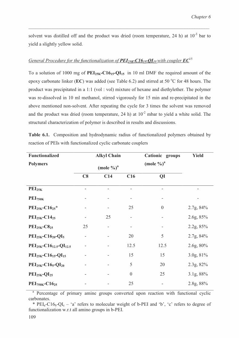
Chapter 6
___________________________________________________________________________
109
solvent was distilled off and the product was dried (room temperature, 24 h) at 10-3
bar to
yield a slightly yellow solid.
General Procedure for the functionalization of PEI25K-C1615-QI15 with coupler EC15
To a solution of 1000 mg of PEI25K-C1615-QI15 in 10 ml DMF the required amount of the
epoxy carbonate linker (EC) was added (see Table 6.2) and stirred at 50 oC for 48 hours. The
product was precipitated in a 1:1 (vol : vol) mixture of hexane and diethylether. The polymer
was re-dissolved in 10 ml methanol, stirred vigorously for 15 min and re-precipitated in the
above mentioned non-solvent. After repeating the cycle for 3 times the solvent was removed
and the product was dried (room temperature, 24 h) at 10-2
mbar to yield a white solid. The
structural characterization of polymer is described in results and discussions.
Table 6.1. Composition and hydrodynamic radius of functionalized polymers obtained by
reaction of PEIs with functionalized cyclic carbonate couplers
Alkyl Chain
(mole %)a
Cationic groups
(mole %)a
Functionalized
Polymers
C8 C14 C16 QI
Yield
PEI25K
PEI750K
PEI25K-C1625*
PEI25K-C1425
PEI25K-C825
PEI25K-C1620-QI5
PEI25K-C1612.5-QI12.5
PEI25K-C1615-QI15
PEI25K-C165-QI20
PEI25K-QI25
PEI750K-C1625
-
-
-
-
25
-
-
-
-
-
-
-
-
-
25
-
-
-
-
-
-
-
-
-
25
-
-
20
12.5
15
5
0
25
-
-
0
-
-
5
12.5
15
20
25
-
-
-
2.7g, 84%
2.6g, 85%
2.2g, 85%
2.7g, 84%
2.6g, 80%
3.0g, 81%
2.3g, 82%
3.1g, 88%
2.8g, 88%
a Percentage of primary amine groups converted upon reaction with functional cyclic
carbonates.
* PEIa-C16b-QIc – ‘a’ refers to molecular weight of b-PEI and ‘b’, ‘c’ refers to degree of
functionalization w.r.t all amino groups in b-PEI.
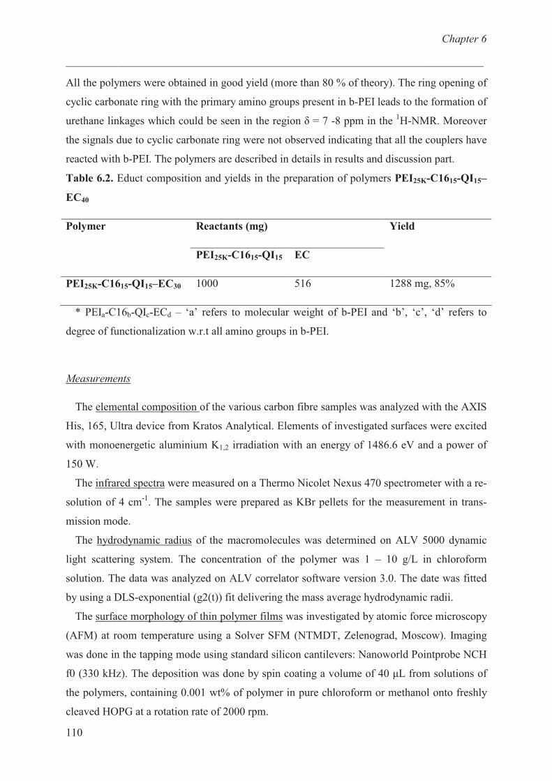
Chapter 6
___________________________________________________________________________
110
All the polymers were obtained in good yield (more than 80 % of theory). The ring opening of
cyclic carbonate ring with the primary amino groups present in b-PEI leads to the formation of
urethane linkages which could be seen in the region � = 7 -8 ppm in the 1H-NMR. Moreover
the signals due to cyclic carbonate ring were not observed indicating that all the couplers have
reacted with b-PEI. The polymers are described in details in results and discussion part.
Table 6.2. Educt composition and yields in the preparation of polymers PEI25K-C1615-QI15–
EC40
Reactants (mg) Polymer
PEI25K-C1615-QI15 EC
Yield
PEI25K-C1615-QI15–EC30 1000 516 1288 mg, 85%
* PEIa-C16b-QIc-ECd – ‘a’ refers to molecular weight of b-PEI and ‘b’, ‘c’, ‘d’ refers to
degree of functionalization w.r.t all amino groups in b-PEI.
Measurements
The elemental composition of the various carbon fibre samples was analyzed with the AXIS
His, 165, Ultra device from Kratos Analytical. Elements of investigated surfaces were excited
with monoenergetic aluminium K1,2 irradiation with an energy of 1486.6 eV and a power of
150 W.
The infrared spectra were measured on a Thermo Nicolet Nexus 470 spectrometer with a re-
solution of 4 cm-1
. The samples were prepared as KBr pellets for the measurement in trans-
mission mode.
The hydrodynamic radius of the macromolecules was determined on ALV 5000 dynamic
light scattering system. The concentration of the polymer was 1 – 10 g/L in chloroform
solution. The data was analyzed on ALV correlator software version 3.0. The date was fitted
by using a DLS-exponential (g2(t)) fit delivering the mass average hydrodynamic radii.
The surface morphology of thin polymer films was investigated by atomic force microscopy
(AFM) at room temperature using a Solver SFM (NTMDT, Zelenograd, Moscow). Imaging
was done in the tapping mode using standard silicon cantilevers: Nanoworld Pointprobe NCH
f0 (330 kHz). The deposition was done by spin coating a volume of 40 �L from solutions of
the polymers, containing 0.001 wt% of polymer in pure chloroform or methanol onto freshly
cleaved HOPG at a rotation rate of 2000 rpm.
Chapter 6
___________________________________________________________________________
111
The amount of polymer adsorbed (�, mg/m2) on graphite (from AFM images) was
calculated using “bearing” function in the Nanoscope 5.12 r5 software. The bearing area (%)
of AFM image times the average height of the molecules and density of the polymer leads to
the amount of polymer adsorbed onto graphite.
Differential scanning calorimetry (DSC) was performed with a Netzsch DSC 204 under ni-
trogen atmosphere with a heating rate of 10oC/min. Calibration was achieved using indium
standard samples, the sample mass was kept between 5 – 15 mg.
Tensile and Photoelastic Measurements
The carbon single fibre / epoxy specimen were clamped in a Rheometric Scientific ‘mini-
mat’ tensile testing device, mounted under a Zeiss Stemi – 2000c polarizing microscope, equi-
pped with a Axiocam ICc3 and analyses was done using Axiovision software. The specimen
was pulled at rate of 1 mm/min. The axial loading was continued until full fragmentation was
reached or the specimen breaks.
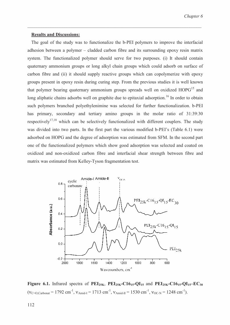
Chapter 6
___________________________________________________________________________
112
Results and Discussions:
The goal of the study was to functionalize the b-PEI polymers to improve the interfacial
adhesion between a polymer – cladded carbon fibre and its surrounding epoxy resin matrix
system. The functionalized polymer should serve for two purposes. (i) It should contain
quaternary ammonium groups or long alkyl chain groups which could adsorb on surface of
carbon fibre and (ii) it should supply reactive groups which can copolymerize with epoxy
groups present in epoxy resin during curing step. From the previous studies it is well known
that polymer bearing quaternary ammonium groups spreads well on oxidized HOPG15
and
long aliphatic chains adsorbs well on graphite due to epitaxial adsorption.16
In order to obtain
such polymers branched polyethylenimine was selected for further functionalization. b-PEI
has primary, secondary and tertiary amino groups in the molar ratio of 31:39:30
respectively17,18
which can be selectively functionalized with different couplers. The study
was divided into two parts. In the first part the various modified b-PEI’s (Table 6.1) were
adsorbed on HOPG and the degree of adsorption was estimated from SFM. In the second part
one of the functionalized polymers which show good adsorption was selected and coated on
oxidized and non-oxidized carbon fibre and interfacial shear strength between fibre and
matrix was estimated from Kelley-Tyson fragmentation test.
Figure 6.1. Infrared spectra of PEI25K, PEI25K-C1615-QI15 and PEI25K-C1615-QI15–EC30
(νC=O,Carbonat = 1792 cm-1
, νAmid-I = 1713 cm-1
, νAmid-II = 1530 cm-1
, νOC-N = 1248 cm-1
).

Chapter 6
___________________________________________________________________________
113
Structural and molecular characterization
Figure 6.1 compares the infrared spectrum of PEI25K, PEI25K-C1615-QI15 and PEI25K-C1615-
QI15–EC30. The bands at 1248 cm-1
(OC-N - stretch), 1530 cm-1
(Amide-I) and 1660 cm-1
(Amide-II) are characteristic for urethane groups, while the band at 1791 cm-1
that appeared
only in PEI25K-C1615-QI15–EC30 was attributed to the >C=O stretching vibration of the cyclic
carbonate ring. Moreover, due to absence of band at 1791 cm-1
in PEI25K-C1615-QI15
indicates that all the cyclic carbonate has reacted with b-PEI.
Figure 6.2 displays the 1H-NMR and
13C-NMR of PEI25K-C1615-QI15–EC30. The
1H-NMR
was difficult to interpret due to overlapping signals caused by ring opening reaction of cyclic
carbonate and epoxides rings. The ring opening of cyclic carbonate ring with primary amine
leads to the formation of an urethane linkage which could be identified in the region � = 7 – 8
ppm (signal 8 & 14). 13
C-NMR shows the characteristic peaks of the cyclic carbonate ring
(signal 23, 24 and 25). Moreover, signals (10, 11, 12, 19, 20, 21) due to ring opening reaction
could also be assigned. The absence of signals coming from an oxirane ring indicates that the
coupler EC has completely reacted with functionalized b-PEI. Thus it can be concluded from
the IR and NMR spectroscopy that a polymer bearing aliphatic tails, quaternary ammonium
groups and cyclic carbonate groups was obtained.
(a)
ppm1.02.03.04.05.06.07.08.0
2311'
24 12'
1012
11
717Q
15Q18Q
1,24-6#
16Q814
A
A
A12'A
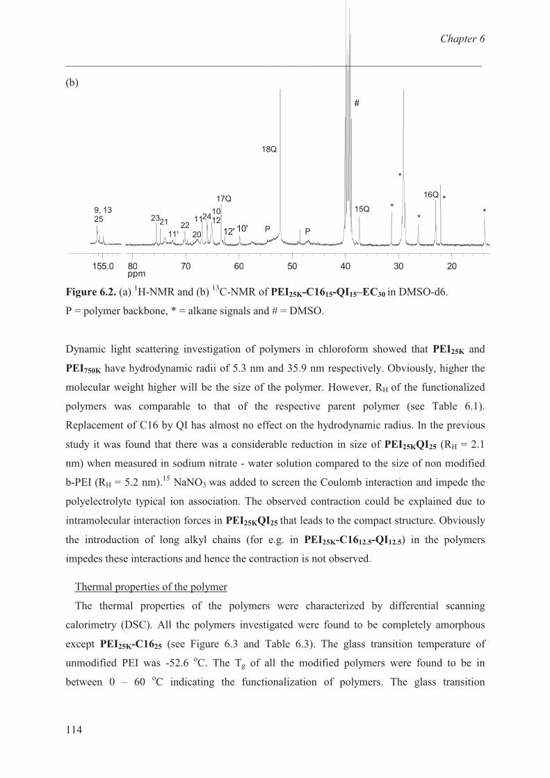
Chapter 6
___________________________________________________________________________
114
(b)
ppm20304050607080
16Q
15Q
#
*
*
*
*
*
18Q
PP10'12'
17Q
10122411
2022
2321
11'
155.0
9, 1325
Figure 6.2. (a) 1H-NMR and (b)
13C-NMR of PEI25K-C1615-QI15–EC30 in DMSO-d6.
P = polymer backbone, * = alkane signals and # = DMSO.
Dynamic light scattering investigation of polymers in chloroform showed that PEI25K and
PEI750K have hydrodynamic radii of 5.3 nm and 35.9 nm respectively. Obviously, higher the
molecular weight higher will be the size of the polymer. However, RH of the functionalized
polymers was comparable to that of the respective parent polymer (see Table 6.1).
Replacement of C16 by QI has almost no effect on the hydrodynamic radius. In the previous
study it was found that there was a considerable reduction in size of PEI25KQI25 (RH = 2.1
nm) when measured in sodium nitrate - water solution compared to the size of non modified
b-PEI (RH = 5.2 nm).15
NaNO3 was added to screen the Coulomb interaction and impede the
polyelectrolyte typical ion association. The observed contraction could be explained due to
intramolecular interaction forces in PEI25KQI25 that leads to the compact structure. Obviously
the introduction of long alkyl chains (for e.g. in PEI25K-C1612.5-QI12.5) in the polymers
impedes these interactions and hence the contraction is not observed.
Thermal properties of the polymer
The thermal properties of the polymers were characterized by differential scanning
calorimetry (DSC). All the polymers investigated were found to be completely amorphous
except PEI25K-C1625 (see Figure 6.3 and Table 6.3). The glass transition temperature of
unmodified PEI was -52.6 oC. The Tg of all the modified polymers were found to be in
between 0 – 60 oC indicating the functionalization of polymers. The glass transition

Chapter 6
___________________________________________________________________________
115
temperature was found to increase with the increase in the amount of charge in the
functionalized polymer.
Figure 6.3. DSC trace of functionalized b-PEI’s. The curves are vertically shifted to avoid
overlapping. Tg is calculated as point of inflection.
Table 6.3. Glass transition and crystallization temperature of functionalized PEI’s.
Polymers Glass Transition
Temperature, oC
Crystallization
Temperature, oC
Hydrodynamic
Radius, RH, nm
PEI25K
PEI750K
PEI25-C825
PEI25K-C1425
PEI25K-C1625
PEI25K-QI5-C1620
PEI25K-C1612.5-QI12.5
PEI25K-C1615-QI15
PEI25K-QI25
PEI25K-C1615-QI15- EC30
PEI750K-C1625
- 53.0
n.d.
14.0
15.2
17.0
19.2
28.3
30.5
58.9
37.5
n.d.
-
n.d.
-
-
42.8
-
-
-
-
-
n.d.
5.28
33.4
3.64
5.46
5.28
5.68
5.80
5.85
n.d.
n.d.
33.4
Chapter 6
___________________________________________________________________________
116
The crystallization of PEI25K-C1625 can be explained due to stiffening of polymer chains
resulted from crystalline packing of bound C16 molecules, which hinders the mobility of
polymer chain. The endothermic peak is at 42.8 oC which is due to melting of C16 alkyl chain
crystals. The b-PEI modified with C8 and C14 were found to be amorphous because of the
length alkyl chain and the flexibility of b-PEI backbone which makes them difficult to
crystallize. The incorporation of charge (QI) into the polymers (PEI25K-QI5-C1620, PEI25K-
C1615-QI15 and PEI25K-QI25) hinders the crystalline packing of the bound C16 molecules and
hence found to be amorphous.
Adsorption Studies
To study the adsorption behaviour, the functionalized polymers were spin coated onto HOPG
from dilute solution in chloroform or methanol and the surface topography was studied by
SFM. The mono-layer coverage of the functionalized polymer was studied depending on (i)
the length of the aliphatic tail (C8, C14 and C16) and (ii) by varying the amount of quaternary
ammonium groups and hexadecane side chains in the polymer (QI and C16).
(i) Effect of aliphatic chain length
b-PEI based functionalized polymers with varying length of alkyl chain (PEI25K-C1625,
PEI25K-C1425, PEI25K-C825) were adsorbed on HOPG from dilute polymer solution in
chloroform (10-3
wt %.). The casting process allows the formation of uniform layers with
monolayer coverage. As typical example Figure 6.4a shows an AFM height image of PEI25K-
C1625 which shows short rods like features with average rod length of 10.2 nm. As understood
from previous studies (Chapter 4) that self assembly of rods leads to single molecule. At this
coverage, the single molecules are difficult to isolate. Thus these rods like features were
attributed to intermolecular and intra-molecular self assembly. A similar type of surface
morphologies was obtained with PEI25K-C1425 as indicated in Figure 6.4b. This image shows
additional stripe patterns forming “rafts” as indicated by an arrow. The periodicity of the
stripes calculated from AFM was 5.6 nm. These stripes can be assigned to unreacted alkyl
chains (hexadecylamine) which are present as impurities in the polymer and forms an
independent layer.
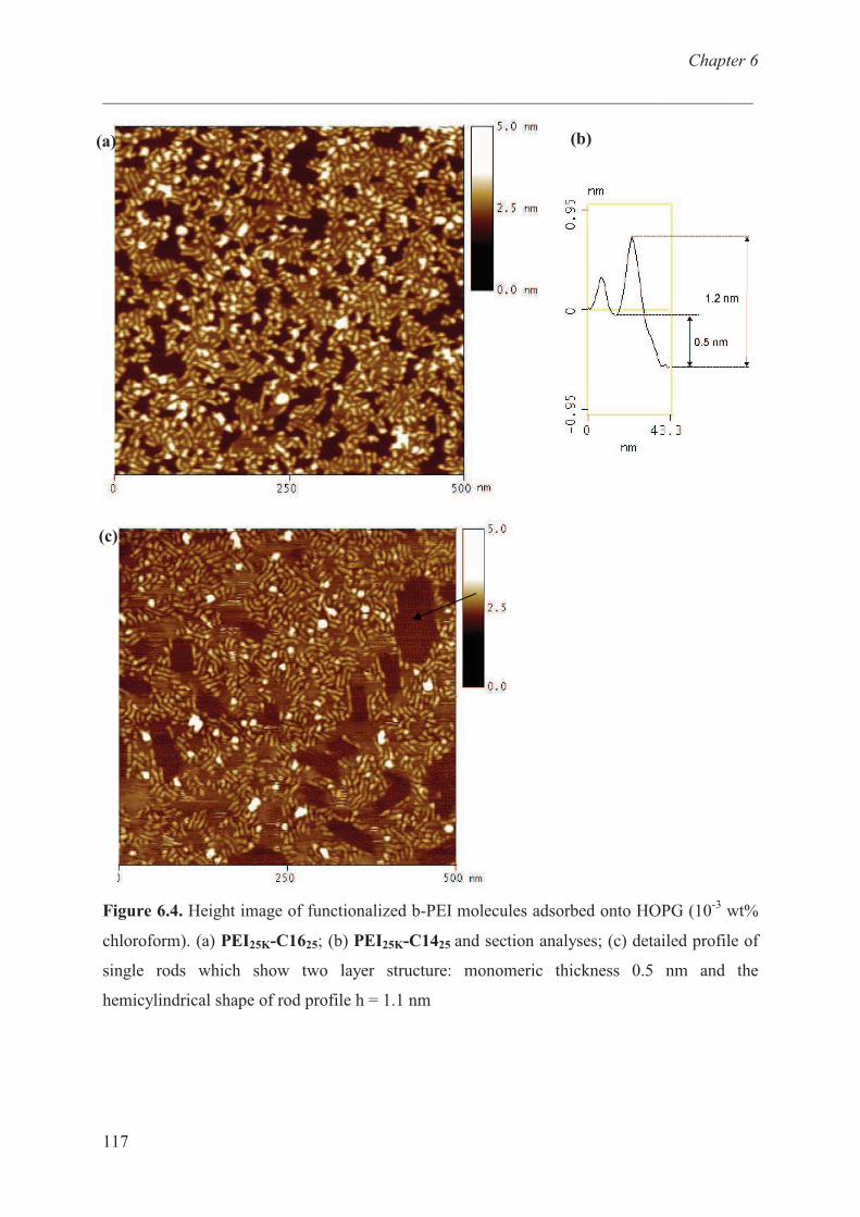
Chapter 6
___________________________________________________________________________
117
Figure 6.4. Height image of functionalized b-PEI molecules adsorbed onto HOPG (10-3
wt%
chloroform). (a) PEI25K-C1625; (b) PEI25K-C1425 and section analyses; (c) detailed profile of
single rods which show two layer structure: monomeric thickness 0.5 nm and the
hemicylindrical shape of rod profile h = 1.1 nm
(c)
(a) (b)
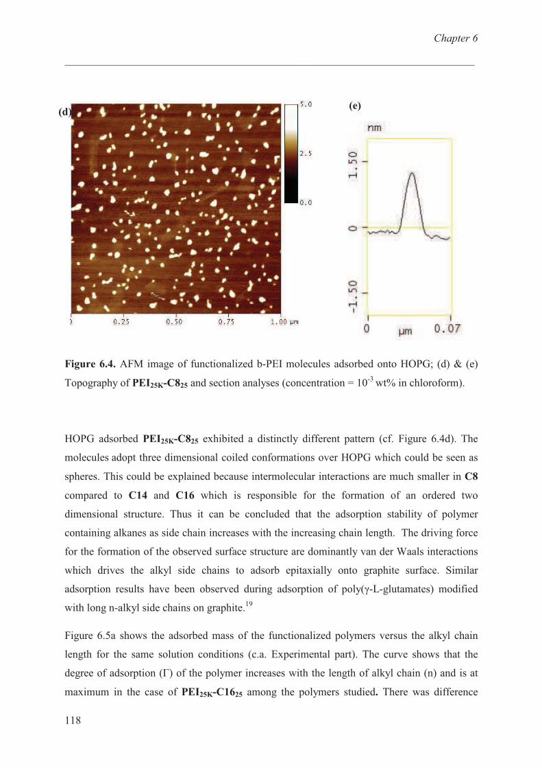
Chapter 6
___________________________________________________________________________
118
Figure 6.4. AFM image of functionalized b-PEI molecules adsorbed onto HOPG; (d) & (e)
Topography of PEI25K-C825 and section analyses (concentration = 10-3
wt% in chloroform).
HOPG adsorbed PEI25K-C825 exhibited a distinctly different pattern (cf. Figure 6.4d). The
molecules adopt three dimensional coiled conformations over HOPG which could be seen as
spheres. This could be explained because intermolecular interactions are much smaller in C8
compared to C14 and C16 which is responsible for the formation of an ordered two
dimensional structure. Thus it can be concluded that the adsorption stability of polymer
containing alkanes as side chain increases with the increasing chain length. The driving force
for the formation of the observed surface structure are dominantly van der Waals interactions
which drives the alkyl side chains to adsorb epitaxially onto graphite surface. Similar
adsorption results have been observed during adsorption of poly(�-L-glutamates) modified
with long n-alkyl side chains on graphite.19
Figure 6.5a shows the adsorbed mass of the functionalized polymers versus the alkyl chain
length for the same solution conditions (c.a. Experimental part). The curve shows that the
degree of adsorption (�) of the polymer increases with the length of alkyl chain (n) and is at
maximum in the case of PEI25K-C1625 among the polymers studied. There was difference
(d) (e)
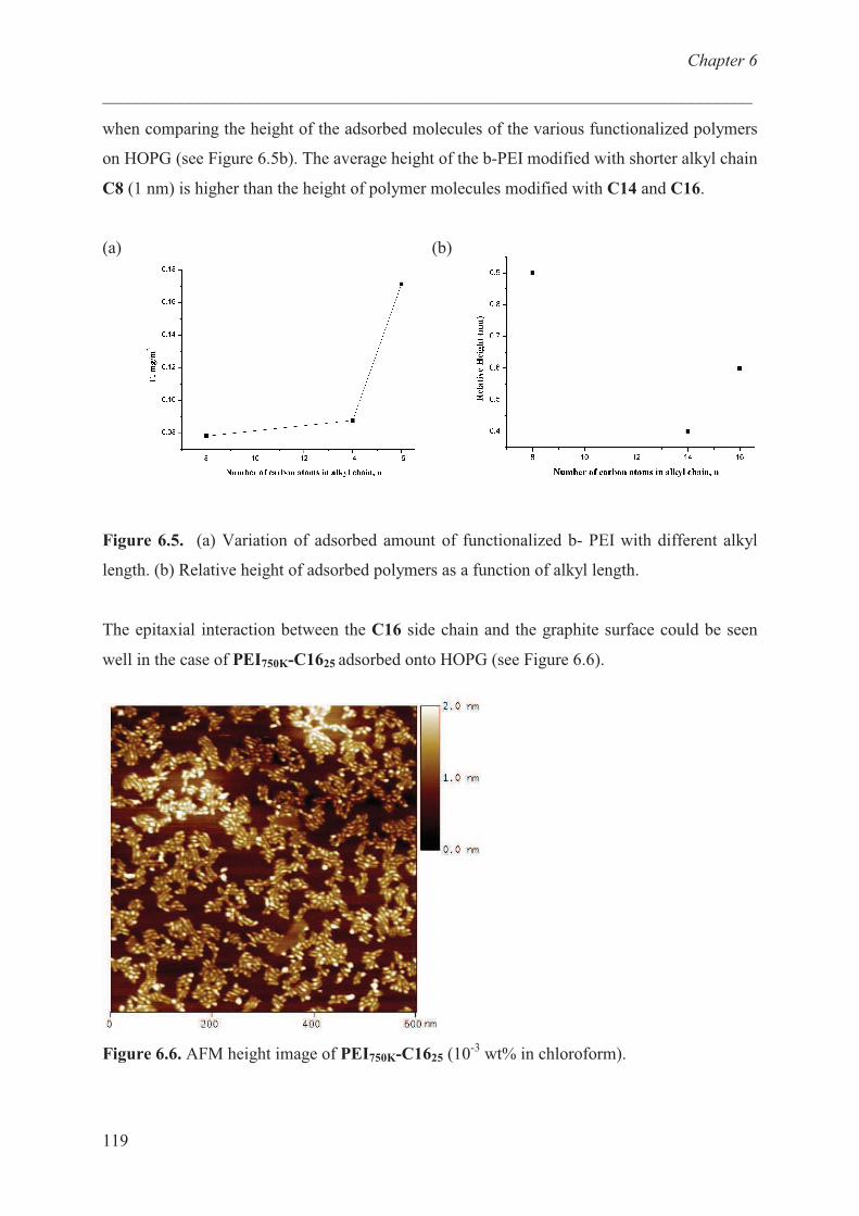
Chapter 6
___________________________________________________________________________
119
when comparing the height of the adsorbed molecules of the various functionalized polymers
on HOPG (see Figure 6.5b). The average height of the b-PEI modified with shorter alkyl chain
C8 (1 nm) is higher than the height of polymer molecules modified with C14 and C16.
(a) (b)
Figure 6.5. (a) Variation of adsorbed amount of functionalized b- PEI with different alkyl
length. (b) Relative height of adsorbed polymers as a function of alkyl length.
The epitaxial interaction between the C16 side chain and the graphite surface could be seen
well in the case of PEI750K-C1625 adsorbed onto HOPG (see Figure 6.6).
Figure 6.6. AFM height image of PEI750K-C1625 (10-3
wt% in chloroform).
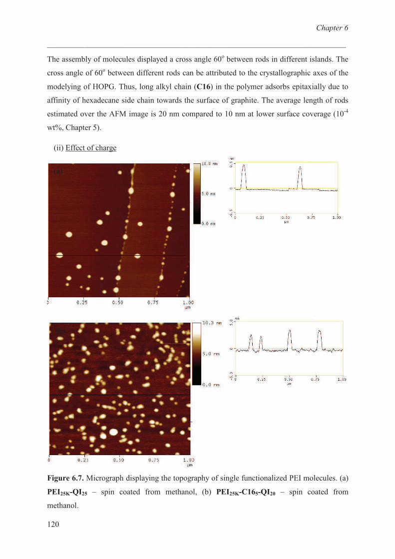
Chapter 6
___________________________________________________________________________
120
The assembly of molecules displayed a cross angle 60o between rods in different islands. The
cross angle of 60o between different rods can be attributed to the crystallographic axes of the
modelying of HOPG. Thus, long alkyl chain (C16) in the polymer adsorbs epitaxially due to
affinity of hexadecane side chain towards the surface of graphite. The average length of rods
estimated over the AFM image is 20 nm compared to 10 nm at lower surface coverage (10-4
wt%, Chapter 5).
(ii) Effect of charge
Figure 6.7. Micrograph displaying the topography of single functionalized PEI molecules. (a)
PEI25K-QI25 – spin coated from methanol, (b) PEI25K-C165-QI20 – spin coated from
methanol.
(a)
(b)
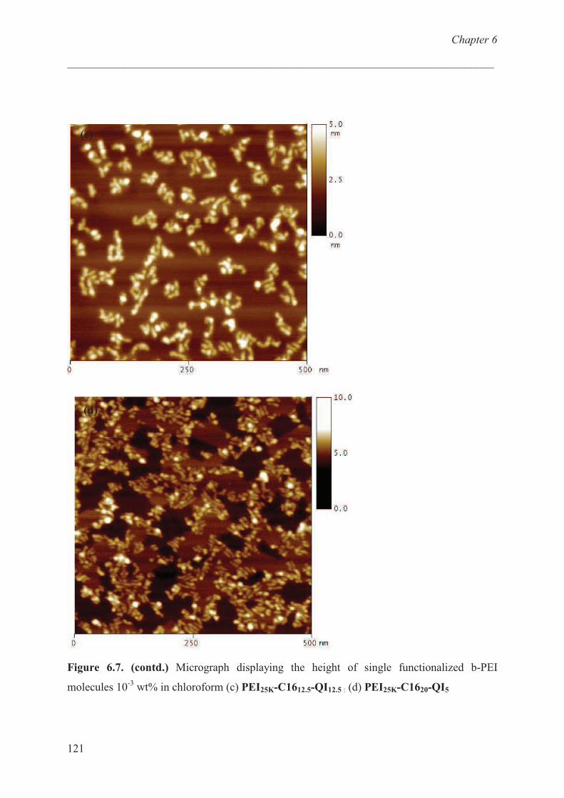
Chapter 6
___________________________________________________________________________
121
Figure 6.7. (contd.) Micrograph displaying the height of single functionalized b-PEI
molecules 10-3
wt% in chloroform (c) PEI25K-C1612.5-QI12.5 : (d) PEI25K-C1620-QI5
(c)
(d)
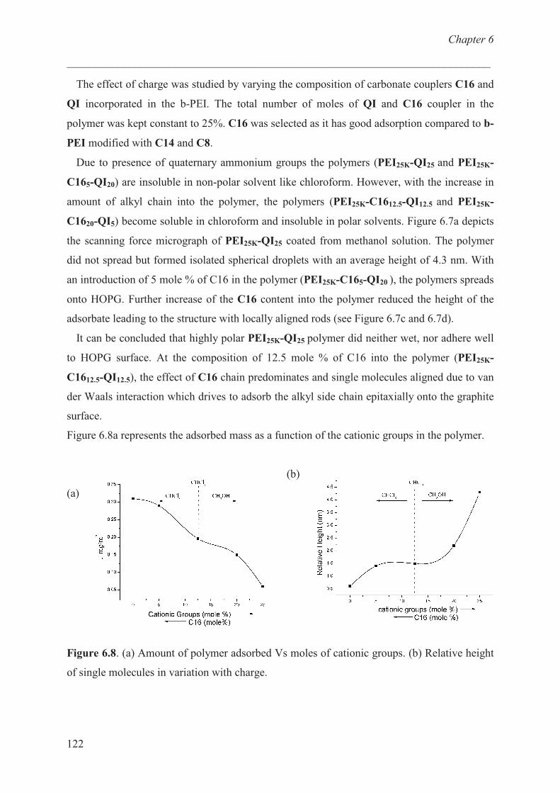
Chapter 6
___________________________________________________________________________
122
The effect of charge was studied by varying the composition of carbonate couplers C16 and
QI incorporated in the b-PEI. The total number of moles of QI and C16 coupler in the
polymer was kept constant to 25%. C16 was selected as it has good adsorption compared to b-
PEI modified with C14 and C8.
Due to presence of quaternary ammonium groups the polymers (PEI25K-QI25 and PEI25K-
C165-QI20) are insoluble in non-polar solvent like chloroform. However, with the increase in
amount of alkyl chain into the polymer, the polymers (PEI25K-C1612.5-QI12.5 and PEI25K-
C1620-QI5) become soluble in chloroform and insoluble in polar solvents. Figure 6.7a depicts
the scanning force micrograph of PEI25K-QI25 coated from methanol solution. The polymer
did not spread but formed isolated spherical droplets with an average height of 4.3 nm. With
an introduction of 5 mole % of C16 in the polymer (PEI25K-C165-QI20 ), the polymers spreads
onto HOPG. Further increase of the C16 content into the polymer reduced the height of the
adsorbate leading to the structure with locally aligned rods (see Figure 6.7c and 6.7d).
It can be concluded that highly polar PEI25K-QI25 polymer did neither wet, nor adhere well
to HOPG surface. At the composition of 12.5 mole % of C16 into the polymer (PEI25K-
C1612.5-QI12.5), the effect of C16 chain predominates and single molecules aligned due to van
der Waals interaction which drives to adsorb the alkyl side chain epitaxially onto the graphite
surface.
Figure 6.8a represents the adsorbed mass as a function of the cationic groups in the polymer.
(a)
(b)
Figure 6.8. (a) Amount of polymer adsorbed Vs moles of cationic groups. (b) Relative height
of single molecules in variation with charge.
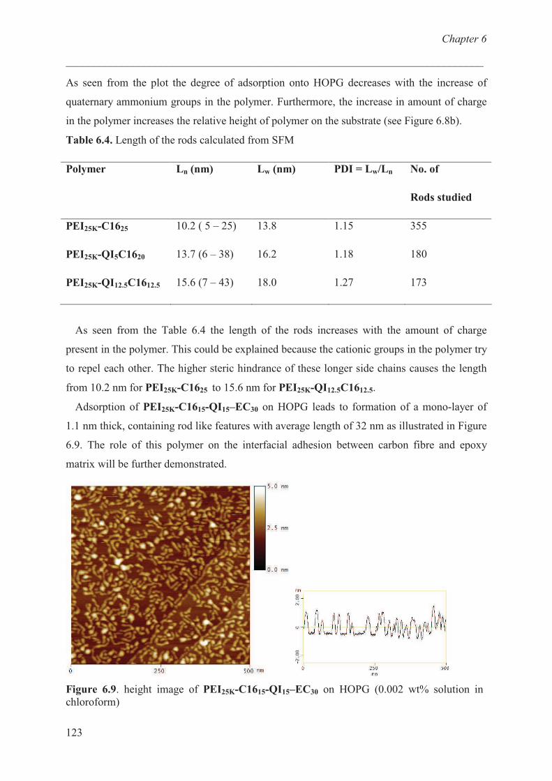
Chapter 6
___________________________________________________________________________
123
As seen from the plot the degree of adsorption onto HOPG decreases with the increase of
quaternary ammonium groups in the polymer. Furthermore, the increase in amount of charge
in the polymer increases the relative height of polymer on the substrate (see Figure 6.8b).
Table 6.4. Length of the rods calculated from SFM
Polymer Ln (nm) Lw (nm) PDI = Lw/Ln No. of
Rods studied
PEI25K-C1625
PEI25K-QI5C1620
PEI25K-QI12.5C1612.5
10.2 ( 5 – 25)
13.7 (6 – 38)
15.6 (7 – 43)
13.8
16.2
18.0
1.15
1.18
1.27
355
180
173
As seen from the Table 6.4 the length of the rods increases with the amount of charge
present in the polymer. This could be explained because the cationic groups in the polymer try
to repel each other. The higher steric hindrance of these longer side chains causes the length
from 10.2 nm for PEI25K-C1625 to 15.6 nm for PEI25K-QI12.5C1612.5.
Adsorption of PEI25K-C1615-QI15–EC30 on HOPG leads to formation of a mono-layer of
1.1 nm thick, containing rod like features with average length of 32 nm as illustrated in Figure
6.9. The role of this polymer on the interfacial adhesion between carbon fibre and epoxy
matrix will be further demonstrated.
Figure 6.9. height image of PEI25K-C1615-QI15–EC30 on HOPG (0.002 wt% solution in
chloroform)
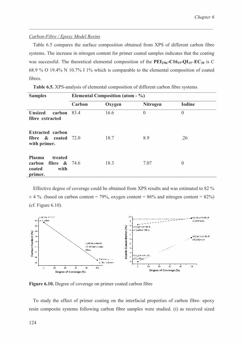
Chapter 6
___________________________________________________________________________
124
Carbon-Fibre / Epoxy Model Resins
Table 6.5 compares the surface composition obtained from XPS of different carbon fibre
systems. The increase in nitrogen content for primer coated samples indicates that the coating
was successful. The theoretical elemental composition of the PEI25K-C1615-QI15–EC30 is C
68.9 % O 19.4% N 10.7% I 1% which is comparable to the elemental composition of coated
fibres.
Table 6.5. XPS-analysis of elemental composition of different carbon fibre systems.
Elemental Composition (atom - %) Samples
Carbon Oxygen Nitrogen Iodine
Unsized carbon
fibre extracted
Extracted carbon
fibre & coated
with primer.
Plasma treated
carbon fibre &
coated with
primer.
83.4
72.0
74.6
16.6
18.7
18.3
0
8.9
7.07
0
.26
0
Effective degree of coverage could be obtained from XPS results and was estimated to 82 %
± 4 %. (based on carbon content = 79%, oxygen content = 86% and nitrogen content = 82%)
(cf. Figure 6.10).
Figure 6.10. Degree of coverage on primer coated carbon fibre
To study the effect of primer coating on the interfacial properties of carbon fibre- epoxy
resin composite systems following carbon fibre samples were studied. (i) as received sized
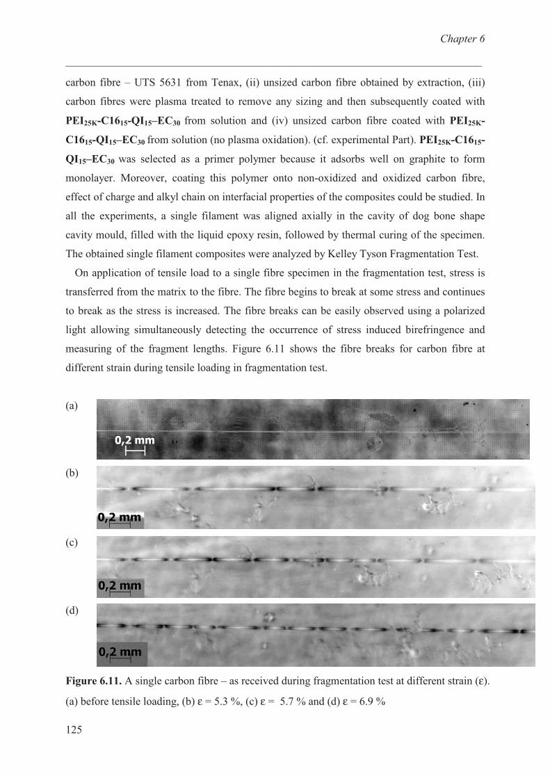
Chapter 6
___________________________________________________________________________
125
carbon fibre – UTS 5631 from Tenax, (ii) unsized carbon fibre obtained by extraction, (iii)
carbon fibres were plasma treated to remove any sizing and then subsequently coated with
PEI25K-C1615-QI15–EC30 from solution and (iv) unsized carbon fibre coated with PEI25K-
C1615-QI15–EC30 from solution (no plasma oxidation). (cf. experimental Part). PEI25K-C1615-
QI15–EC30 was selected as a primer polymer because it adsorbs well on graphite to form
monolayer. Moreover, coating this polymer onto non-oxidized and oxidized carbon fibre,
effect of charge and alkyl chain on interfacial properties of the composites could be studied. In
all the experiments, a single filament was aligned axially in the cavity of dog bone shape
cavity mould, filled with the liquid epoxy resin, followed by thermal curing of the specimen.
The obtained single filament composites were analyzed by Kelley Tyson Fragmentation Test.
On application of tensile load to a single fibre specimen in the fragmentation test, stress is
transferred from the matrix to the fibre. The fibre begins to break at some stress and continues
to break as the stress is increased. The fibre breaks can be easily observed using a polarized
light allowing simultaneously detecting the occurrence of stress induced birefringence and
measuring of the fragment lengths. Figure 6.11 shows the fibre breaks for carbon fibre at
different strain during tensile loading in fragmentation test.
(a)
(b)
(c)
(d)
Figure 6.11. A single carbon fibre – as received during fragmentation test at different strain (ε).
(a) before tensile loading, (b) ε = 5.3 %, (c) ε = 5.7 % and (d) ε = 6.9 %
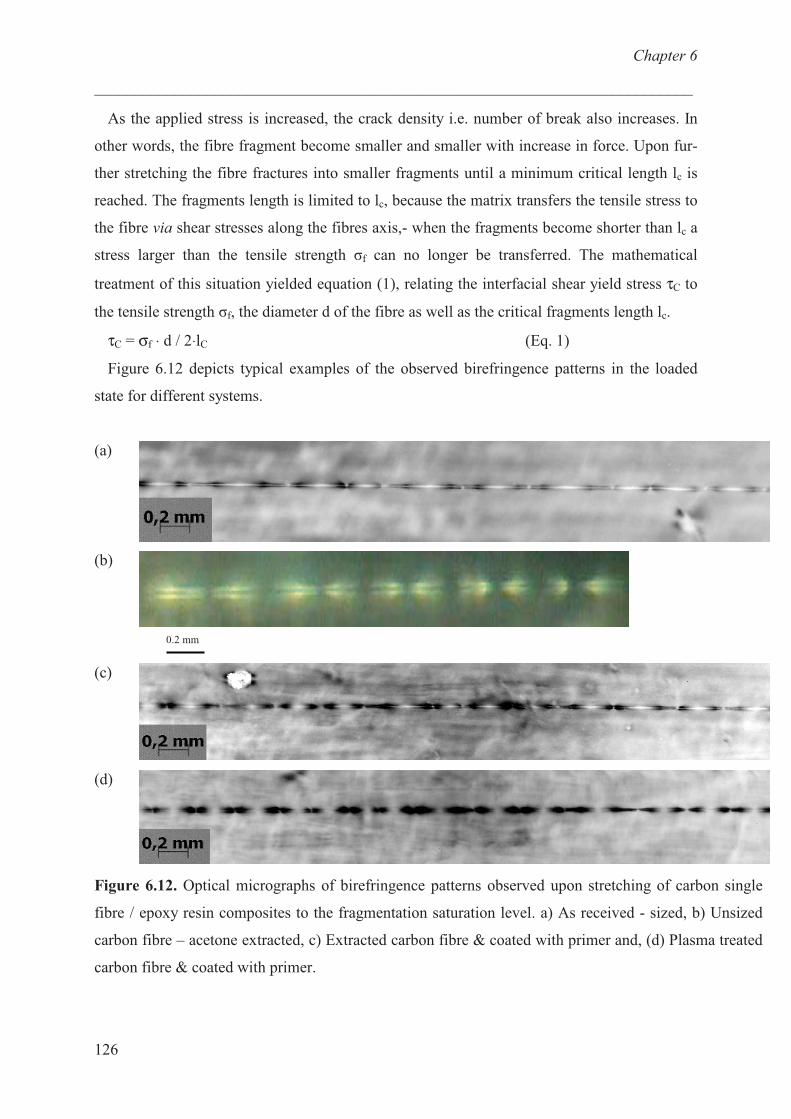
Chapter 6
___________________________________________________________________________
126
As the applied stress is increased, the crack density i.e. number of break also increases. In
other words, the fibre fragment become smaller and smaller with increase in force. Upon fur-
ther stretching the fibre fractures into smaller fragments until a minimum critical length lc is
reached. The fragments length is limited to lc, because the matrix transfers the tensile stress to
the fibre via shear stresses along the fibres axis,- when the fragments become shorter than lc a
stress larger than the tensile strength �f can no longer be transferred. The mathematical
treatment of this situation yielded equation (1), relating the interfacial shear yield stress τC to
the tensile strength �f, the diameter d of the fibre as well as the critical fragments length lc.
τC = σf ⋅ d / 2⋅lC (Eq. 1)
Figure 6.12 depicts typical examples of the observed birefringence patterns in the loaded
state for different systems.
(a)
(b)
(c)
(d)
Figure 6.12. Optical micrographs of birefringence patterns observed upon stretching of carbon single
fibre / epoxy resin composites to the fragmentation saturation level. a) As received - sized, b) Unsized
carbon fibre – acetone extracted, c) Extracted carbon fibre & coated with primer and, (d) Plasma treated
carbon fibre & coated with primer.
0.2 mm

Chapter 6
___________________________________________________________________________
127
In the vicinity of any fragment tip an intense photoelastic region developed, resulting in the
shown stress pattern with alternating dark and light areas. The birefringence pattern was
usually symmetric at both sides of the fibre ends. As expected no new fibre breaks occurred
once the critical fragment length was reached, even if the applied tensile load was
continuously increased further. Figure 6.13 compares the crack density of different carbon
fibre – epoxy resin systems in the single fibre fragmentation test.
Figure 6.13. Crack density of different carbon fibre systems as a function of applied
strain. * Crack density is equal to number of breaks at saturation divided by original gauge
length of the specimen.
In the presence of polymer primer (PEI25K-C1615-QI15–EC30) at the non-oxidized and
oxidized carbon fibre/matrix interface the fibre fragmentation starts at an elongation (ε ≅
Chapter 6
___________________________________________________________________________
128
0.038) that is about 30 % below that of the unsized primer polymer sample (ε ≅ 0.055). At
elongation (ε ≅ 0.07), crack density showed a plateau or saturation in all the studied samples.
Table 6.6. Average values of the critical number of fibre fractures NC, the critical fibre length
lc and of the interfacial shear strength τC obtained from Kelley/Tyson fragmentation tests with
different carbon fibre / epoxy resins systems.
Sample Average
Number of
Fragments, Nc
Critical
fragment
length, lc (�m)
lc/d* Interfacial
Shear Strength,
�, [MPa]
Sized carbon fibre
– as received
Unsized carbon
fibre – acetone
extracted
Extracted carbon
fibre & coated with
primer
Plasma treated
carbon fibre &
coated with primer
42 ± 2
33 ± 3
47 ± 2
48 ± 3
370 ± 6
410 ± 5
340 ± 5
330 ± 10
52.9 ± 1
58.6 ± 1
48.5 ± 1
47.1 ± 2
45.4 ± 1
40.9 ± 1
49.5 ± 1
51.0 ± 2
* Diameter of the single carbon fibre is assumed to be 7 �m.
The interfacial shear strength was calculated assuming that the tensile strength σf at critical
fibre length is same for all the carbon fibre systems. There was marked improvement in the
interfacial shear strength of primer coated carbon fibre samples (�C ~ 25 % for non oxidized &
coated with primer and �C ~ 21 % for oxidized and coated with primer) compared to unsized
carbon fibre system (cf. Table 6.6). Moreover, the interfacial shear strength of non-oxidized
and oxidized carbon fibre samples (both samples are coated with primer PEI25K-C1615-QI15–
EC30) was found to be same. The polymer primer consists of equal amount (moles) of alkyl
chains and quaternary ammonium groups. It is well known that quaternary ammonium groups
adsorbs well on oxidized carbon fibre system whereas they does not like to wet non polar
Chapter 6
___________________________________________________________________________
129
carbon fibre surfaces. Alkyl chains are known to adsorb epitaxialy onto non oxidized carbon
fibre. Since, the interfacial strength obtained is similar for both the systems, it can be
concluded that this primer polymer has enough alkyl (C16) chains which allows them to
adsorb onto non – oxidized carbon fibres. The conclusion is further supported from the
adsorption study of this polymer onto graphite (cf. Figure 6.9).
The similar test was carried out for as received carbon fibre systems from Toho Tenax. 13 %
improvement in interfacial shear strength of primer sized carbon fibre system compared to the
strength of the commercial fibres was observed.
Conclusions
A series of functional b-PEI containing alkyl and ammonium functionalities were successfully
synthesized and characterized. The adsorption behaviour of the polymers was studied onto
graphite demonstrating the formation of mono-layer coverage by means of atomic force
microscopy. The amount of adsorbed material was found to increase with the length of the
used alkyl chain and maximum adsorption was observed for the C16 modified b-PEI.
Furthermore, the degree of adsorption onto graphite decreased with the increase in amount of
quaternary ammonium groups in the polymer. The incorporation of additional cyclic carbonate
groups in a b-PEI bearing 15 mole % C16 and 15 mole % QI groups did not considerably
change the adsorption behaviour as indicated by AFM. PEI25K-C1615-QI15–EC30 adsorbed
well on carbon fibre as indicated by XPS measurements. When embedded in an epoxy matrix
the adsorbed polymer caused an increase of the interfacial shear strength for about 35 % as
compared to non sized embedded fibre.
References
1 Kawaguchi, M.; Takahashi, A. Adv. Colloid Interface Sci. 1992, 37, 219.
2 Bajpai, A. K. Prog. Polym. Sci. 1997, 22, 523.
3 Schneider, M.; Brinkmann, M.; Moehwald, H. Macromolecules 2003, 36, 9510.
4 Ren, B.; Cheng, Z.; Tong, Z.; Liu, X.; Wang, C.; Zeng, F. Macromolecules 2006, 39,
6552.
5 Rabe, J. P.; Buchholz, S. Science 1991, 253, 424.
Chapter 6
___________________________________________________________________________
130
6 Thunemann, A. F.; Kubowicz, S.; Pietsch, U. Langmuir 2000, 16, 8562.
7 Fleer, G. J.; Cohen, Stuart M. A.; Scheutjens, J. M. H. M.; Cosgrove, T.; Vincent, B.
Polymers at Interfaces; Chapman and Hall: London, 1993, 272.
8 Olanya, G.; Iruthayaraj, J.; Poptoshev, E.; Makuska, R.; Vareikis, A.; Claesson, P. M.
Langmuir 2008, 24, 5341.
9 Pasquier, N.; Keul, H.; Moeller, M. Designed Monomers and Polymers 2005, 8, 679.
10 Pasquier, N.; Keul, H.; Heine, E.; Moeller, M. Biomacromolecules 2007, 8, 2874.
11 Moeller, M.; Beginn, U.; Keul, H.; Thomas, H. European Patent 2006, Patent Nr.
1710282.
12 Ubaghs, L. PhD Thesis, RWTH Aachen 2005.
13 Kelley, A.; Tyson, W. R. J. Mech. Phys. Solids 1965, 13, 329.
14 Pasquier, N.. PhD Thesis, RWTH Aachen 2008.
15 Goel, V.; Beginn, U.; Mourran, A.; Möller, M. Macromolecules 2008, 41, 8187.
16 Yin, S.; Wang, C.; Qiu, X.; Xu, B.; Bai, C. Surf. Interface Anal. 2001, 32, 248.
17 Lukovin, G. M.; Pshezhetsky, V. S.; Murtazaeva, G. A. Eur. Polym. J. 1973, 9, 559.
18 Idris, S. A.; Mkhatresh, O. A.; Heatley, F. Poly. Int. 2006, 55, 1040.
19 Imase, T.; Ohira, A.; Okoshi, K.; Sano, N.; Kawauchi, S.; Watanabe, J.; Kunitake, M.
Macromolecules 2003, 36, 1865.
Chapter 7
___________________________________________________________________________
131
Chapter 7. Polymer bearing UV polymerizable
groups.
Introduction:
The surface modification of textile fibres has been an active and important field of research
and industrial development since the introduction of synthetic fibres. A large number of
methods have been described in the literature, e.g. surface oxidation by oxygen plasma
introduces hydroxyl, carboxyl and ketone groups, ammonia plasma introduces ammonium
groups on the surfaces.1,2,3
Other methods include surface coating with or without chemical
bonding to the fibre surface. The objective of the treatments is to make the inert and
hydrophobic fibre surface more hydrophilic. High energy radiations like � ray and electron
beams have been applied to change the fibre surface. 4
In presence of monomer and
photoinitiator, the irradiation initiates the polymerization by free radical or ionic mechanisms.
The limitation to this treatment is that the radiation penetrates the bulk polymer and affects
the mechanical properties. Chemical methods are found to be better and more specific.
Surface radicals on the fibres can be introduced by peroxide, redox or azo dye systems and
can be subsequently reacted with monomers.5,6
Oster and coworkers7,8
and Stannett and
coworkers9,10
were first to introduce the photochemical methods for polymer modification. In
most of the photo-initiated surface modification, the grafting efficiency is low and irradiation
time usually too long for industrial applications.11,12
Photo-grafting has proven to be highly
effective and attracted attention due to its significant advantages: easy and controllable
operations, low cost, mild reaction conditions, potentially reducing or even avoiding negative
effects on the bulk polymer. In 1983, Ranby et al. developed two new approaches for photo-
initiated surface grafting, (i) a batch process for films where the initiator and monomer are
transferred through vapour phase during UV irradiation13
, and (ii) a continuous process14
for
films, fibres and yarns of any polymer where the substrate is pre-soaked in a solution of
monomer and initiator and then UV irradiated in an inert atmosphere. The grafting takes place
in the thin layer of solution on the surface of the substrate.
The prepolymer concept is a widely used for preparation of crosslinked materials. The
advantage of prepolymer is (i) polymerization and crosslinking are independent steps; (ii) it
does not contain any toxic monomers and can therefore be handled under less stringent
conditions; and (iii) the properties of the prepolymer can be tailored offering potential for
applications like coatings. In the present study a prepolymer containing cationic and photo-
polymerizable groups will be prepared by polymer analogous reaction of a branched
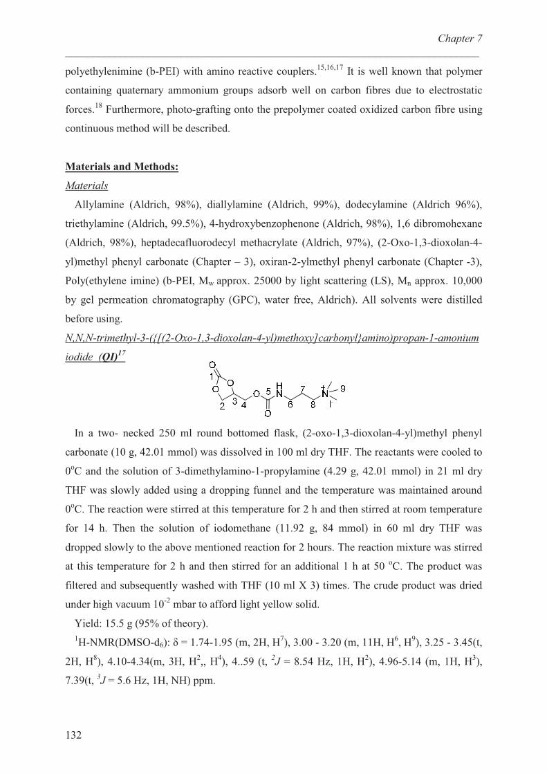
Chapter 7
___________________________________________________________________________
132
polyethylenimine (b-PEI) with amino reactive couplers.15,16,17
It is well known that polymer
containing quaternary ammonium groups adsorb well on carbon fibres due to electrostatic
forces.18
Furthermore, photo-grafting onto the prepolymer coated oxidized carbon fibre using
continuous method will be described.
Materials and Methods:
Materials
Allylamine (Aldrich, 98%), diallylamine (Aldrich, 99%), dodecylamine (Aldrich 96%),
triethylamine (Aldrich, 99.5%), 4-hydroxybenzophenone (Aldrich, 98%), 1,6 dibromohexane
(Aldrich, 98%), heptadecafluorodecyl methacrylate (Aldrich, 97%), (2-Oxo-1,3-dioxolan-4-
yl)methyl phenyl carbonate (Chapter – 3), oxiran-2-ylmethyl phenyl carbonate (Chapter -3),
Poly(ethylene imine) (b-PEI, Mw approx. 25000 by light scattering (LS), Mn approx. 10,000
by gel permeation chromatography (GPC), water free, Aldrich). All solvents were distilled
before using.
N,N,N-trimethyl-3-({[(2-Oxo-1,3-dioxolan-4-yl)methoxy]carbonyl}amino)propan-1-amonium
iodide (QI)17
In a two- necked 250 ml round bottomed flask, (2-oxo-1,3-dioxolan-4-yl)methyl phenyl
carbonate (10 g, 42.01 mmol) was dissolved in 100 ml dry THF. The reactants were cooled to
0oC and the solution of 3-dimethylamino-1-propylamine (4.29 g, 42.01 mmol) in 21 ml dry
THF was slowly added using a dropping funnel and the temperature was maintained around
0oC. The reaction were stirred at this temperature for 2 h and then stirred at room temperature
for 14 h. Then the solution of iodomethane (11.92 g, 84 mmol) in 60 ml dry THF was
dropped slowly to the above mentioned reaction for 2 hours. The reaction mixture was stirred
at this temperature for 2 h and then stirred for an additional 1 h at 50 oC. The product was
filtered and subsequently washed with THF (10 ml X 3) times. The crude product was dried
under high vacuum 10-2
mbar to afford light yellow solid.
Yield: 15.5 g (95% of theory).
1H-NMR(DMSO-d6): � = 1.74-1.95 (m, 2H, H
7), 3.00 - 3.20 (m, 11H, H
6, H
9), 3.25 - 3.45(t,
2H, H8), 4.10-4.34(m, 3H, H
2,, H
4), 4..59 (t,
2J = 8.54 Hz, 1H, H
2), 4.96-5.14 (m, 1H, H
3),
7.39(t, 3J = 5.6 Hz, 1H, NH) ppm.
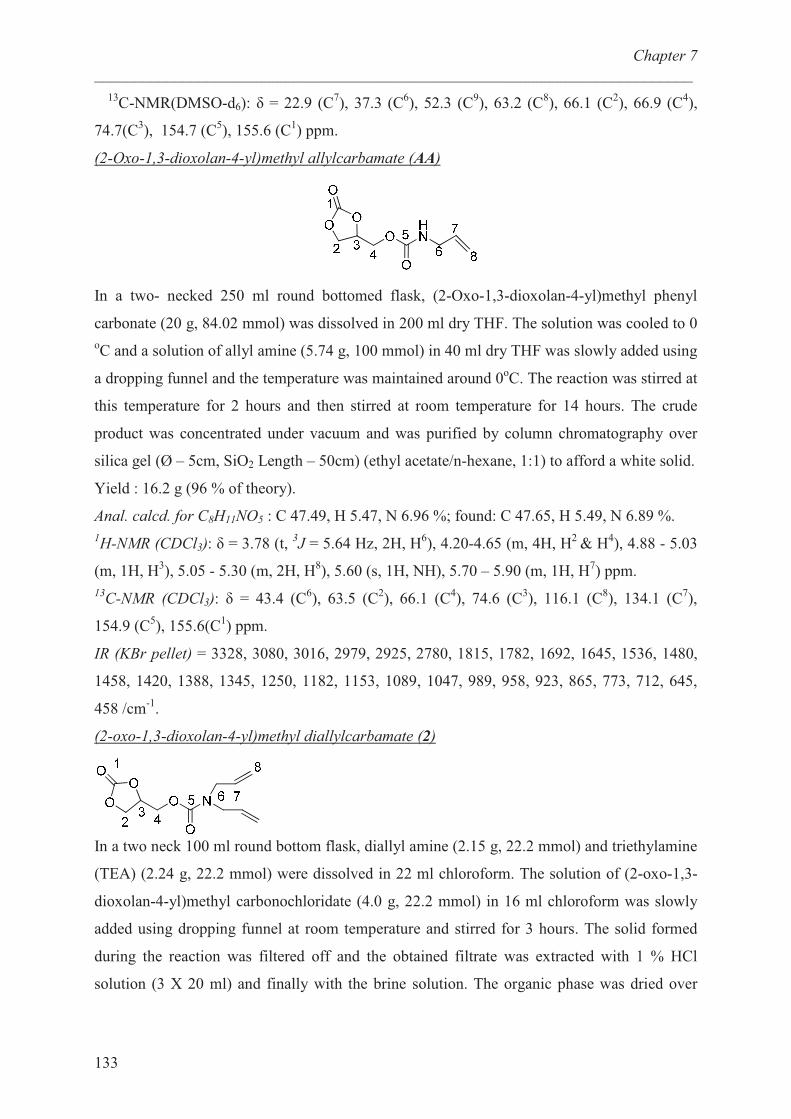
Chapter 7
___________________________________________________________________________
133
13C-NMR(DMSO-d6): � = 22.9 (C
7), 37.3 (C
6), 52.3 (C
9), 63.2 (C
8), 66.1 (C
2), 66.9 (C
4),
74.7(C3), 154.7 (C
5), 155.6 (C
1) ppm.
(2-Oxo-1,3-dioxolan-4-yl)methyl allylcarbamate (AA)
In a two- necked 250 ml round bottomed flask, (2-Oxo-1,3-dioxolan-4-yl)methyl phenyl
carbonate (20 g, 84.02 mmol) was dissolved in 200 ml dry THF. The solution was cooled to 0
oC and a solution of allyl amine (5.74 g, 100 mmol) in 40 ml dry THF was slowly added using
a dropping funnel and the temperature was maintained around 0oC. The reaction was stirred at
this temperature for 2 hours and then stirred at room temperature for 14 hours. The crude
product was concentrated under vacuum and was purified by column chromatography over
silica gel (Ø – 5cm, SiO2 Length – 50cm) (ethyl acetate/n-hexane, 1:1) to afford a white solid.
Yield : 16.2 g (96 % of theory).
Anal. calcd. for C8H11NO5 : C 47.49, H 5.47, N 6.96 %; found: C 47.65, H 5.49, N 6.89 %.
1H-NMR (CDCl3): � = 3.78 (t,
3J = 5.64 Hz, 2H, H
6), 4.20-4.65 (m, 4H, H
2 & H
4), 4.88 - 5.03
(m, 1H, H3), 5.05 - 5.30 (m, 2H, H
8), 5.60 (s, 1H, NH), 5.70 – 5.90 (m, 1H, H
7) ppm.
13C-NMR (CDCl3): � = 43.4 (C
6), 63.5 (C
2), 66.1 (C
4), 74.6 (C
3), 116.1 (C
8), 134.1 (C
7),
154.9 (C5), 155.6(C
1) ppm.
IR (KBr pellet) = 3328, 3080, 3016, 2979, 2925, 2780, 1815, 1782, 1692, 1645, 1536, 1480,
1458, 1420, 1388, 1345, 1250, 1182, 1153, 1089, 1047, 989, 958, 923, 865, 773, 712, 645,
458 /cm-1
.
(2-oxo-1,3-dioxolan-4-yl)methyl diallylcarbamate (2)
In a two neck 100 ml round bottom flask, diallyl amine (2.15 g, 22.2 mmol) and triethylamine
(TEA) (2.24 g, 22.2 mmol) were dissolved in 22 ml chloroform. The solution of (2-oxo-1,3-
dioxolan-4-yl)methyl carbonochloridate (4.0 g, 22.2 mmol) in 16 ml chloroform was slowly
added using dropping funnel at room temperature and stirred for 3 hours. The solid formed
during the reaction was filtered off and the obtained filtrate was extracted with 1 % HCl
solution (3 X 20 ml) and finally with the brine solution. The organic phase was dried over

Chapter 7
___________________________________________________________________________
134
anhydrous Na2SO4. After removal of solvents under vacuum, the diallyl carbonate coupler
was obtained as colorless oil.
Yield : 4.4 g (85 % of theory).
Anal. calcd. for C11H11NO5 : C 54.77, H 6.27, N 5.81 %; found: C54.35, H 6.23, N 5.80 %.
1H-NMR (CDCl3): � = 3.85 (t,
3J = 5.64 Hz, 4H, H
6), 4.20-4.65 (m, 4H, H
2 & H
4), 4.90 - 5.00
(m, 1H, H3), 5.05 - 5.30 (m, 4H, H
8), 5.70 – 5.90 (m, 2H, H
7) ppm.
13C-NMR (CDCl3): � = 48.7, 49.5 (C
6), 64.1 (C
2), 65.9 (C
4), 74.3 (C
3), 116.8, 117.6 (C
8),
132.8 (C7), 154.5 (C
5), 155.1 (C
1) ppm.
IR (KBr pellet) = 3328, 3080, 3016, 2979, 2925, 2780, 1815, 1782, 1692, 1645, 1536, 1480,
1458, 1420, 1388, 1345, 1250, 1182, 1153, 1089, 1047, 989, 958, 923, 865, 773, 712, 645,
458 /cm-1
.
4-((diallylamino)methyl)-1,3-dioxolan-2-one (3)
In a two-necked 100 ml flask equipped with a condenser, oxiran-2-ylmethyl phenyl carbonate
(2 g, 10.30 mmol) and diallyl amine (2 g, 20.60 mmol) were dissolved in 15 ml THF and the
reaction was carried out for 24 hours at 60 oC. The crude product was extracted with 1 % HCl
solution (5 ml X 3 times) and once with brine solution. The organic phase was dried over
Na2SO4. After removal of solvents under vacuum, the functionalized coupler was obtained as
colorless oil.
Yield : 1.4 g (70 % of theory).
Anal. calcd. for C10H15NO3 : C 60.90, H 7.67, N 7.10 %; found: C 61.20, H 7.82, N 7.05 %.
1H-NMR (CDCl3): � = 3.85 (t,
3J = 5.64 Hz, 4H, H
5), 4.20-4.60 (m, 4H, H
2 & H
4), 4.90 - 5.00
(m, 1H, H3), 5.05 - 5.30 (m, 4H, H
7), 5.70 – 5.90 (m, 2H, H
6) ppm.
13C-NMR (CDCl3): � = 48.7, 49.4 (C
5), 64.1 (C
2), 66.0 (C
4), 74.3 (C
3), 116.7, 117.5 (C
7),
132.8 (C8), 154.5 (C
5), 155.0 (C
1) ppm.
{4-[(6-Bromohexyl)oxy]phenyl}(phenyl)methanone (PI)
A 3-necked round-bottomed flask equipped with a mechanical stirrer and a reflux condenser
was charged with 500 ml cyclohexanone. The apparatus was flushed with nitrogen, and under
Chapter 7
___________________________________________________________________________
135
vigorous stirring 4-hydroxybenzophenone (50.00 g, 250 mmol) and 1,6 dibromohexane (125
g, 512 mmol) were added and dissolved in the solvent. Subsequently potassium iodide (1 g)
and potassium carbonate (52 g, 375 mmol) were added with vigorous stirring. The viscous
solution was refluxed at 190oC for 5 h. The reaction was monitored with the help of TLC
(KG-60 silica gel plate, hexane: ethyl acetate-6:1). The solid was separated by hot filtration
and the solvent was removed from the filtrate in the rotary vacuum evaporator to give a
viscous solution. The photoinitiator was purified by recrystallization from ethanol (1:5l) to
yield white solid.
Yield: 65.8 g (71% of theory).
Anal. calcd. for C19H21BrO2 : C 63.17, H 5.86, N 0.00 %; found: C 63.08, H 5.53, N 0.01 %.
1H-NMR (CDCl3): � = 1.44-1.60 (m, 4H, H
16& H
17), 1.75-1.96 (m, 4H, H
15& H
18), 3.42 (t,
2J
= 6.75 Hz, 2H, H19
), 3.42 (t, 2J = 6.37 Hz, 2H, H
14), 6.80 – 7.80 (m, 9H, phenyl) ppm.
13C-NMR (CDCl3): � = 25.2 (C
16), 27.8 (C
17), 28.9 (C
18), 32.6 (C
15), 33.7 (C
19), 67.9 (C
14),
113.9 (2C, C12
, C10
), 128.1 (2C, C2, C
4), 129.6 (2C, C
1, C
5), 129.9 (C
8), 131.8 (C
3), 132.5 (2C,
C9, C
13), 138.2 (C
6), 162.7 (C
11), 195.4 (C
7) ppm.
IR (KBr pellet) = 3433, 2938, 2861, 1651, 1600, 1576, 1507, 1445, 1419, 1316, 1281, 1255,
1173, 1149, 1114, 1027, 938, 923, 846, 794, 741, 701, 637, 624 / cm−1
.
Reaction of photoinitiator (PI) with b-PEI (PEI25K-PI)
In a two - neck round bottom flask equipped with the condenser, 1 g of b-PEI was reacted
with photoinitiator (83 mg, 0.23 mmol) in 10 ml DMF for 16 h under nitrogen atmosphere.
After addition of 40 ml of hexane, the formed two phase system was stirred vigorously for 15
min. The upper layer consisting of hexane and DMF was removed by decantation. The
procedure was repeated many times until bottom layer became viscous. The polymer was
dried under vacuum and was obtained as viscous liquid. The reaction was monitored by TLC
using chloroform as a solvent. Note, that b-PEI is UV inactive whereas PI is UV active. At
the start of the reaction, two different spots could be seen on TLC plate. As the reaction
proceeded, the UV active spot due to PI disappeared and spot due to b-PEI turned UV active
indicating that PI was covalently bonded to the polymer. Yield: 830 mg (84% of theory).
Chapter 7
___________________________________________________________________________
136
Reaction of N,N,N-trimethyl-3-({[(2-Oxo-1,3-dioxolan-4-l)methoxy]carbonyl}amino)propan-
1-amonium iodide (QI), (2-Oxo-1,3-dioxolan-4-yl)methyl allylcarbamate (AA) and
photoinitiator (PI) with b-PEI (PEI25K-QI15-AA8-PI1)
In a two-neck flask equipped with the condenser, b-PEI (2.58 g), QI (3.49 g, 9 mmol), AA
(0.96 g, 4.8 mmol) and PI (216 mg, 0.60 mmol) were dissolved in 70 ml DMF and the
reactants were stirred at 50 oC for 18 h. The crude product was precipitated in a 1:1 (vol : vol)
mixture of hexane and diethylether (500 ml). The polymer was re-dissolved in 10 ml
methanol, stirred vigorously for 15 min and re-precipitated in the above mentioned non-
solvent. After repeating the cycle for 3 times the solvent was removed and the product was
dried (room temperature, 24 h) at 1.3 Pa to yield a white solid.
Measurements
1H- and
13C-NMR spectra were recorded on a Bruker DPX-300 FT-NMR spectrometer at
300 MHz and 75 MHz respectively. Chloroform-d (CDCl3) and dimethylsulfoxide-d6
(DMSO- d6) were used as solvents, and tetramethylsilane (TMS) was used as internal
standard.
The infrared spectra were measured on a Thermo Nicolet Nexus 470 spectrometer with a re-
solution of 4 cm-1
. The samples were prepared as KBr pellets for the measurement in trans-
mission mode.
The hydrodynamic diameter of the macromolecules was determined on a Zetasizer NanoZS
ZEN3500 dynamic light scattering system. The concentration of the polymer was 1 – 10 g/L
in 0.5M sodium nitrate solution.
Differential scanning calorimetry (DSC) was performed with a Netzsch DSC 204 under ni-
trogen atmosphere with a heating rate of 10oC/min. Calibration was achieved using indium
standard samples, the sample mass was kept between 5 – 15 mg.
Carbon, hydrogen and nitrogen elemental analyses were performed on a Hearaeus CHN-O
Rapid Elementar Vario El instrument.
The elemental composition of the various carbon fibre samples was analyzed with the AXIS
His, 165, Ultra device from Kratos Analytical. Elements of investigated surfaces were excited
with monoenergetic aluminium K1,2 irradiation with an energy of 1486.6 eV and power of
150W.
To prepare Quat-Primer sized carbon fibres the commercially obtained carbon fibre roving
was treated with continuous oxygen plasma machine. The fibre was put on a roller (length :
35 cm, Ø – 9 cm) and evacuated in a plasma discharger, AK 550 Roth and Rau to a pressure
of 10-3
bar. The following parameters were used: O2 gas flow, 100 ft3 / min; working pressure

Chapter 7
___________________________________________________________________________
137
= 1 mbar, microwave power = 150 W, motor speed = 4 m/min. Immediately after the plasma
treatment, the fibres were dip-coated in a solution of PEI25K-QI15-AA8-PI1 (0.1 wt%
polymer) in methanol (weight of fibre : volume of polymer solution - 300 mg : 15 mL) and
were dried under vacuum (14 h, 50 oC, membrane pump).
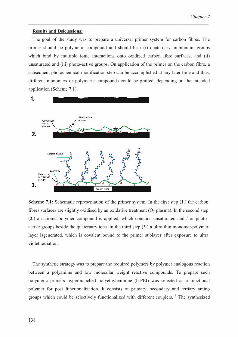
Chapter 7
___________________________________________________________________________
138
Results and Dsicussions:
The goal of the study was to prepare a universal primer system for carbon fibres. The
primer should be polymeric compound and should bear (i) quaternary ammonium groups
which bind by multiple ionic interactions onto oxidized carbon fibre surfaces, and (ii)
unsaturated and (iii) photo-active groups. On application of the primer on the carbon fibre, a
subsequent photochemical modification step can be accomplished at any later time and thus,
different monomers or polymeric compounds could be grafted, depending on the intended
application (Scheme 7.1).
Scheme 7.1: Schematic representation of the primer system. In the first step (1.) the carbon
fibres surfaces are slightly oxidised by an oxidative treatment (O2 plasma). In the second step
(2.) a cationic polymer compound is applied, which contains unsaturated and / or photo-
active groups beside the quaternary ions. In the third step (3.) a ultra thin monomer/polymer
layer isgenerated, which is covalent bound to the primer sublayer after exposure to ultra
violet radiation.
The synthetic strategy was to prepare the required polymers by polymer analogous reaction
between a polyamine and low molecular weight reactive compounds. To prepare such
polymeric primers hyperbranched polyethylenimine (b-PEI) was selected as a functional
polymer for post functionalization. It consists of primary, secondary and tertiary amino
groups which could be selectively functionalized with different couplers.19
The synthesized
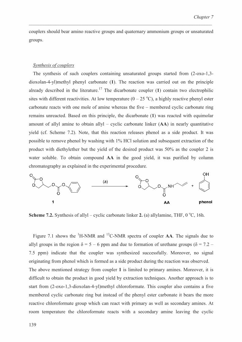
Chapter 7
___________________________________________________________________________
139
couplers should bear amino reactive groups and quaternary ammonium groups or unsaturated
groups.
Synthesis of couplers
The synthesis of such couplers containing unsaturated groups started from (2-oxo-1,3-
dioxolan-4-yl)methyl phenyl carbonate (1). The reaction was carried out on the principle
already described in the literature.17
The dicarbonate coupler (1) contain two electrophilic
sites with different reactivities. At low temperature (0 – 25 oC), a highly reactive phenyl ester
carbonate reacts with one mole of amine whereas the five – membered cyclic carbonate ring
remains unreacted. Based on this principle, the dicarbonate (1) was reacted with equimolar
amount of allyl amine to obtain allyl – cyclic carbonate linker (AA) in nearly quantitative
yield (cf. Scheme 7.2). Note, that this reaction releases phenol as a side product. It was
possible to remove phenol by washing with 1% HCl solution and subsequent extraction of the
product with diethylether but the yield of the desired product was 50% as the coupler 2 is
water soluble. To obtain compound AA in the good yield, it was purified by column
chromatography as explained in the experimental procedure.
Scheme 7.2. Synthesis of allyl – cyclic carbonate linker 2. (a) allylamine, THF, 0 oC, 16h.
Figure 7.1 shows the 1H-NMR and
13C-NMR spectra of coupler AA. The signals due to
allyl groups in the region � = 5 – 6 ppm and due to formation of urethane groups (� = 7.2 –
7.5 ppm) indicate that the coupler was synthesized successfully. Moreover, no signal
originating from phenol which is formed as a side product during the reaction was observed.
The above mentioned strategy from coupler 1 is limited to primary amines. Moreover, it is
difficult to obtain the product in good yield by extraction techniques. Another approach is to
start from (2-oxo-1,3-dioxolan-4-yl)methyl chloroformate. This coupler also contains a five
membered cyclic carbonate ring but instead of the phenyl ester carbonate it bears the more
reactive chloroformate group which can react with primary as well as secondary amines. At
room temperature the chloroformate reacts with a secondary amine leaving the cyclic
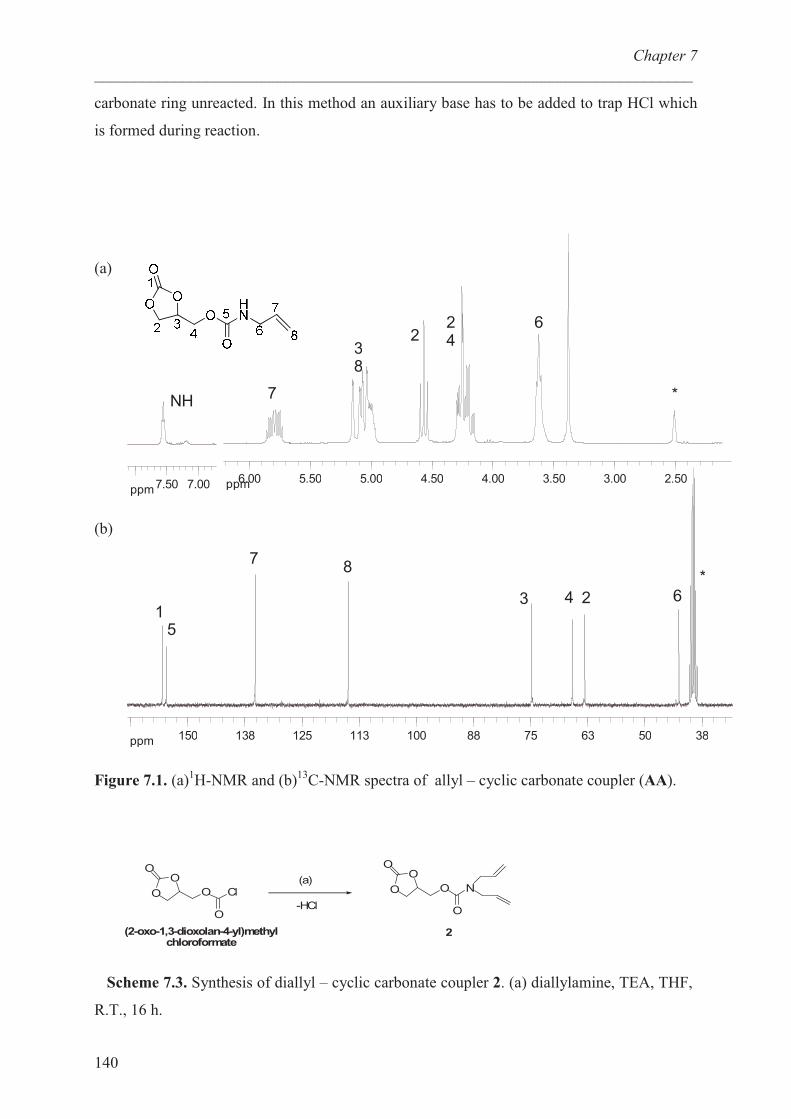
Chapter 7
___________________________________________________________________________
140
carbonate ring unreacted. In this method an auxiliary base has to be added to trap HCl which
is formed during reaction.
(a)
ppm 2.503.003.504.004.505.005.506.00
*
6242
38
7
ppm 7.007.50
NH
(b)
ppm 3850637588100113125138150
*6243
87
51
Figure 7.1. (a)1H-NMR and (b)
13C-NMR spectra of allyl – cyclic carbonate coupler (AA).
O
OO
O
O
Cl O
OO
O
O
N(a)
2(2-oxo-1,3-dioxolan-4-yl)methyl chloroformate
-HCl
Scheme 7.3. Synthesis of diallyl – cyclic carbonate coupler 2. (a) diallylamine, TEA, THF,
R.T., 16 h.
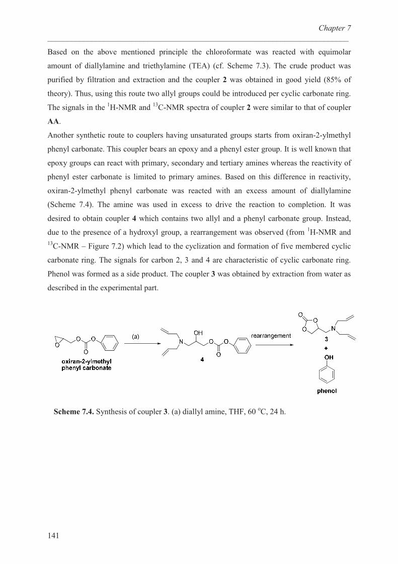
Chapter 7
___________________________________________________________________________
141
Based on the above mentioned principle the chloroformate was reacted with equimolar
amount of diallylamine and triethylamine (TEA) (cf. Scheme 7.3). The crude product was
purified by filtration and extraction and the coupler 2 was obtained in good yield (85% of
theory). Thus, using this route two allyl groups could be introduced per cyclic carbonate ring.
The signals in the 1H-NMR and
13C-NMR spectra of coupler 2 were similar to that of coupler
AA.
Another synthetic route to couplers having unsaturated groups starts from oxiran-2-ylmethyl
phenyl carbonate. This coupler bears an epoxy and a phenyl ester group. It is well known that
epoxy groups can react with primary, secondary and tertiary amines whereas the reactivity of
phenyl ester carbonate is limited to primary amines. Based on this difference in reactivity,
oxiran-2-ylmethyl phenyl carbonate was reacted with an excess amount of diallylamine
(Scheme 7.4). The amine was used in excess to drive the reaction to completion. It was
desired to obtain coupler 4 which contains two allyl and a phenyl carbonate group. Instead,
due to the presence of a hydroxyl group, a rearrangement was observed (from 1H-NMR and
13C-NMR – Figure 7.2) which lead to the cyclization and formation of five membered cyclic
carbonate ring. The signals for carbon 2, 3 and 4 are characteristic of cyclic carbonate ring.
Phenol was formed as a side product. The coupler 3 was obtained by extraction from water as
described in the experimental part.
Scheme 7.4. Synthesis of coupler 3. (a) diallyl amine, THF, 60 oC, 24 h.
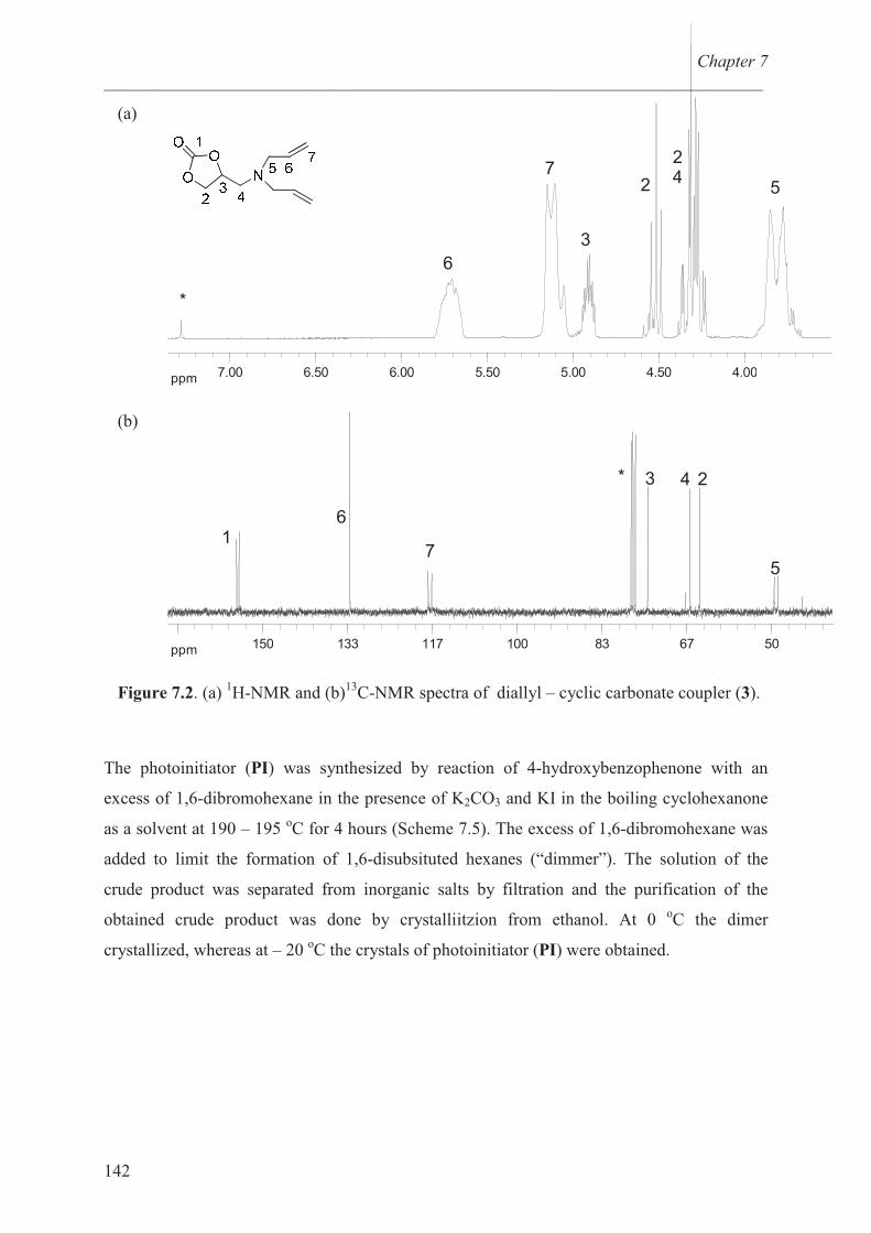
Chapter 7
___________________________________________________________________________
142
(a)
ppm 4.004.505.005.506.006.507.00
6
7
3
2
24
5
*
(b)
ppm 506783100117133150
5
243*
7
61
Figure 7.2. (a) 1H-NMR and (b)
13C-NMR spectra of diallyl – cyclic carbonate coupler (3).
The photoinitiator (PI) was synthesized by reaction of 4-hydroxybenzophenone with an
excess of 1,6-dibromohexane in the presence of K2CO3 and KI in the boiling cyclohexanone
as a solvent at 190 – 195 oC for 4 hours (Scheme 7.5). The excess of 1,6-dibromohexane was
added to limit the formation of 1,6-disubsituted hexanes (“dimmer”). The solution of the
crude product was separated from inorganic salts by filtration and the purification of the
obtained crude product was done by crystalliitzion from ethanol. At 0 oC the dimer
crystallized, whereas at – 20 oC the crystals of photoinitiator (PI) were obtained.
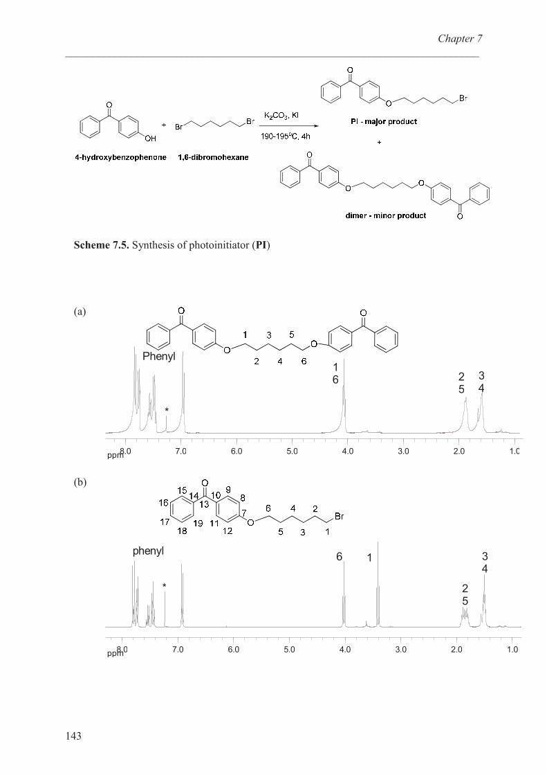
Chapter 7
___________________________________________________________________________
143
Scheme 7.5. Synthesis of photoinitiator (PI)
(a)
ppm 1.02.03.04.05.06.07.08.0
16 3
425
*
Phenyl
(b)
ppm 1.02.03.04.05.06.07.08.0
34
25
16phenyl
*
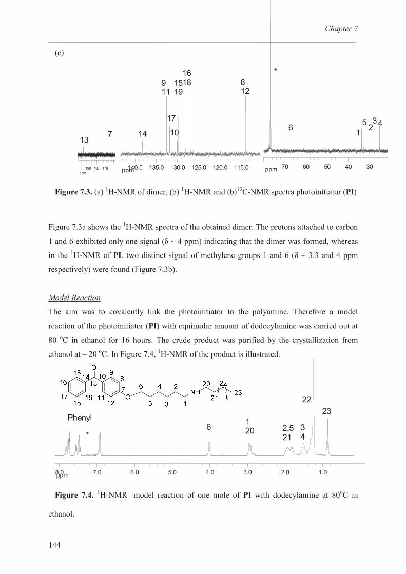
Chapter 7
___________________________________________________________________________
144
(c)
ppm 3040506070
432
5
16
*
ppm 115.0120.0125.0130.0135.0140.0
812
161815
19
10
17
911
14
������������
713
Figure 7.3. (a) 1H-NMR of dimer, (b)
1H-NMR and (b)
13C-NMR spectra photoinitiator (PI)
Figure 7.3a shows the 1H-NMR spectra of the obtained dimer. The protons attached to carbon
1 and 6 exhibited only one signal (� ~ 4 ppm) indicating that the dimer was formed, whereas
in the 1H-NMR of PI, two distinct signal of methylene groups 1 and 6 (� ~ 3.3 and 4 ppm
respectively) were found (Figure 7.3b).
Model Reaction
The aim was to covalently link the photoinitiator to the polyamine. Therefore a model
reaction of the photoinitiator (PI) with equimolar amount of dodecylamine was carried out at
80 oC in ethanol for 16 hours. The crude product was purified by the crystallization from
ethanol at – 20 oC. In Figure 7.4,
1H-NMR of the product is illustrated.
ppm 1.02.03.04.05.06.07.08.0
23
22
1206
*
Phenyl
34
2,521
Figure 7.4.1H-NMR -model reaction of one mole of PI with dodecylamine at 80
oC in
ethanol.
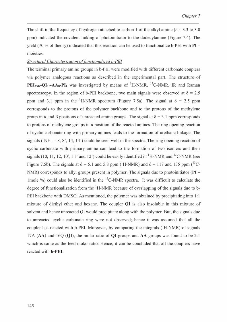
Chapter 7
___________________________________________________________________________
145
The shift in the frequency of hydrogen attached to carbon 1 of the alkyl amine (� ~ 3.3 to 3.0
ppm) indicated the covalent linking of photoinitiator to the dodecylamine (Figure 7.4). The
yield (70 % of theory) indicated that this reaction can be used to functionalize b-PEI with PI –
moieties.
Structural Characterization of functionalized b-PEI
The terminal primary amino groups in b-PEI were modified with different carbonate couplers
via polymer analogous reactions as described in the experimental part. The structure of
PEI25K-QI15-AA8-PI1 was investigated by means of 1H-NMR,
13C-NMR, IR and Raman
spectroscopy. In the region of b-PEI backbone, two main signals were observed at � = 2.5
ppm and 3.1 ppm in the 1H-NMR spectrum (Figure 7.5a). The signal at � = 2.5 ppm
corresponds to the protons of the polymer backbone and to the protons of the methylene
group in � and � positions of unreacted amine groups. The signal at � = 3.1 ppm corresponds
to protons of methylene groups in � position of the reacted amines. The ring opening reaction
of cyclic carbonate ring with primary amines leads to the formation of urethane linkage. The
signals (-NH- = 8, 8’, 14, 14’) could be seen well in the spectra. The ring opening reaction of
cyclic carbonate with primary amine can lead to the formation of two isomers and their
signals (10, 11, 12, 10’, 11’ and 12’) could be easily identified in 1H-NMR and
13C-NMR (see
Figure 7.5b). The signals at � = 5.1 and 5.8 ppm (1H-NMR) and � = 117 and 135 ppm (
13C-
NMR) corresponds to allyl groups present in polymer. The signals due to photoinitiator (PI –
1mole %) could also be identified in the 13
C-NMR spectra. It was difficult to calculate the
degree of functionalization from the 1H-NMR because of overlapping of the signals due to b-
PEI backbone with DMSO. As mentioned, the polymer was obtained by precipitating into 1:1
mixture of diethyl ether and hexane. The coupler QI is also insoluble in this mixture of
solvent and hence unreacted QI would precipitate along with the polymer. But, the signals due
to unreacted cyclic carbonate ring were not observed; hence it was assumed that all the
coupler has reacted with b-PEI. Moreover, by comparing the integrals (1H-NMR) of signals
17A (AA) and 16Q (QI), the molar ratio of QI groups and AA groups was found to be 2:1
which is same as the feed molar ratio. Hence, it can be concluded that all the couplers have
reacted with b-PEI.
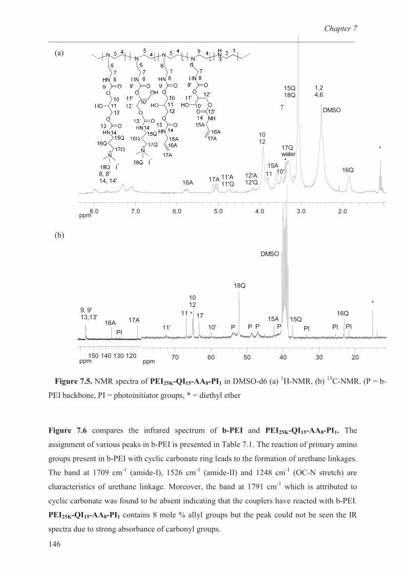
Chapter 7
___________________________________________________________________________
146
(a)
ppm2.03.04.05.06.07.08.0
16A17A
15A
15Q18Q
1,24,6
DMSO
11'A11'Q
12'A12'Q
1012
11 10' 16Q
17Qwater
*
*
8, 8'14, 14'
(b)
ppm203040506070
11'
11
1012
17
10'
18Q
15Q16Q
DMSO
15A
*
*
P P P P PIPIPI
ppm120130140150
17A16A
9, 9'13,13'
PI
Figure 7.5. NMR spectra of PEI25K-QI15-AA8-PI1 in DMSO-d6 (a) 1H-NMR, (b)
13C-NMR. (P = b-
PEI backbone, PI = photoinitiator groups, * = diethyl ether
Figure 7.6 compares the infrared spectrum of b-PEI and PEI25K-QI15-AA8-PI1. The
assignment of various peaks in b-PEI is presented in Table 7.1. The reaction of primary amino
groups present in b-PEI with cyclic carbonate ring leads to the formation of urethane linkages.
The band at 1709 cm-1
(amide-I), 1526 cm-1
(amide-II) and 1248 cm-1
(OC-N stretch) are
characteristics of urethane linkage. Moreover, the band at 1791 cm-1
which is attributed to
cyclic carbonate was found to be absent indicating that the couplers have reacted with b-PEI.
PEI25K-QI15-AA8-PI1 contains 8 mole % allyl groups but the peak could not be seen the IR
spectra due to strong absorbance of carbonyl groups.
7
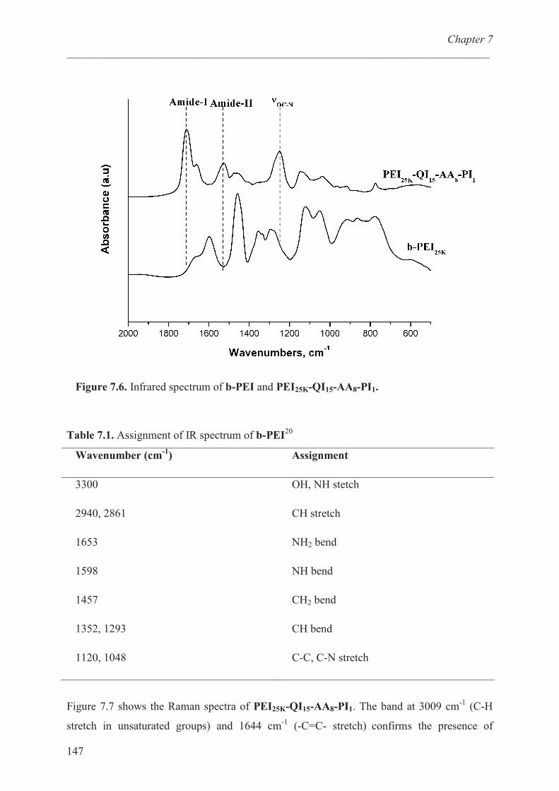
Chapter 7
___________________________________________________________________________
147
Figure 7.6. Infrared spectrum of b-PEI and PEI25K-QI15-AA8-PI1.
Table 7.1. Assignment of IR spectrum of b-PEI20
Wavenumber (cm-1
) Assignment
3300
2940, 2861
1653
1598
1457
1352, 1293
1120, 1048
OH, NH stetch
CH stretch
NH2 bend
NH bend
CH2 bend
CH bend
C-C, C-N stretch
Figure 7.7 shows the Raman spectra of PEI25K-QI15-AA8-PI1. The band at 3009 cm-1
(C-H
stretch in unsaturated groups) and 1644 cm-1
(-C=C- stretch) confirms the presence of
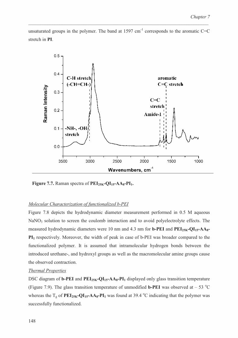
Chapter 7
___________________________________________________________________________
148
unsaturated groups in the polymer. The band at 1597 cm-1
corresponds to the aromatic C=C
stretch in PI.
Figure 7.7. Raman spectra of PEI25K-QI15-AA8-PI1.
Molecular Characterization of functionalized b-PEI
Figure 7.8 depicts the hydrodynamic diameter measurement performed in 0.5 M aqueous
NaNO3 solution to screen the coulomb interaction and to avoid polyelectrolyte effects. The
measured hydrodynamic diameters were 10 nm and 4.3 nm for b-PEI and PEI25K-QI15-AA8-
PI1 respectively. Moreover, the width of peak in case of b-PEI was broader compared to the
functionalized polymer. It is assumed that intramolecular hydrogen bonds between the
introduced urethane-, and hydroxyl groups as well as the macromolecular amine groups cause
the observed contraction.
Thermal Properties
DSC diagram of b-PEI and PEI25K-QI15-AA8-PI1 displayed only glass transition temperature
(Figure 7.9). The glass transition temperature of unmodified b-PEI was observed at – 53 oC
whereas the Tg of PEI25K-QI15-AA8-PI1 was found at 39.4 oC indicating that the polymer was
successfully functionalized.
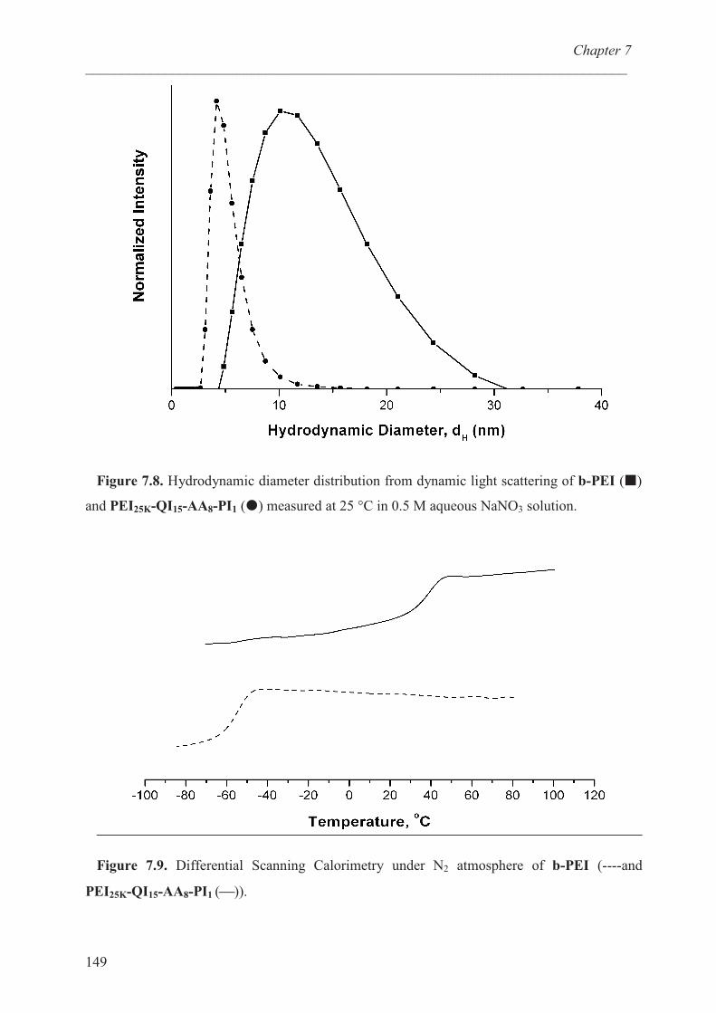
Chapter 7
___________________________________________________________________________
149
Figure 7.8. Hydrodynamic diameter distribution from dynamic light scattering of b-PEI (�)
and PEI25K-QI15-AA8-PI1 (�) measured at 25 °C in 0.5 M aqueous NaNO3 solution.
Figure 7.9. Differential Scanning Calorimetry under N2 atmosphere of b-PEI (----and
PEI25K-QI15-AA8-PI1 ()).
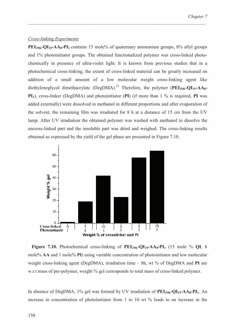
Chapter 7
___________________________________________________________________________
150
Cross-linking Experiments
PEI25K-QI15-AA8-PI1 contains 15 mole% of quaternary ammonium groups, 8% allyl groups
and 1% photoinitiator groups. The obtained functionalized polymer was cross-linked photo-
chemically in presence of ultra-violet light. It is known from previous studies that in a
photochemical cross-linking, the extent of cross-linked material can be greatly increased on
addition of a small amount of a low molecular weight cross-linking agent like
diethyleneglycol dimethacrylate (DegDMA).21
Therefore, the polymer (PEI25K-QI15-AA8-
PI1), cross-linker (DegDMA) and photoinitiator (PI) (if more than 1 % is required, PI was
added externally) were dissolved in methanol in different proportions and after evaporation of
the solvent, the remaining film was irradiated for 8 h at a distance of 15 cm from the UV
lamp. After UV irradiation the obtained polymer was washed with methanol to dissolve the
uncross-linked part and the insoluble part was dried and weighed. The cross-linking results
obtained as expressed by the yield of the gel phase are presented in Figure 7.10.
Figure 7.10. Photochemical cross-linking of PEI25K-QI15-AA8-PI1 (15 mole % QI, 8
mole% AA and 1 mole% PI) using variable concentration of photoinitiator and low molecular
weight cross-linking agent (DegDMA), irradiation time – 8h, wt % of DegDMA and PI are
w.r.t mass of pre-polymer, weight % gel corresponds to total mass of cross-linked polymer.
In absence of DegDMA, 1% gel was formed by UV irradiation of PEI25K-QI15-AA8-PI1. An
increase in concentration of photoinitiator from 1 to 10 wt % leads to an increase in the
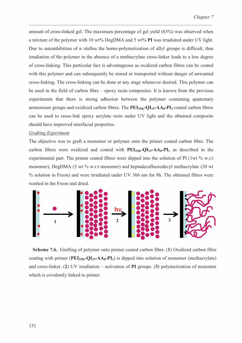
Chapter 7
___________________________________________________________________________
151
amount of cross-linked gel. The maximum percentage of gel yield (63%) was observed when
a mixture of the polymer with 10 wt% DegDMA and 5 wt% PI was irradiated under UV light.
Due to autoinhibition of � olefins the homo-polymerization of allyl groups is difficult, thus
irradiation of the polymer in the absence of a methacrylate cross-linker leads to a low degree
of cross-linking. This particular fact is advantageous as oxidized carbon fibres can be coated
with this polymer and can subsequently be stored or transported without danger of unwanted
cross-linking. The cross-linking can be done at any stage whenever desired. This polymer can
be used in the field of carbon fibre – epoxy resin composites. It is known from the previous
experiments that there is strong adhesion between the polymer containing quaternary
ammonium groups and oxidized carbon fibres. The PEI25K-QI15-AA8-PI1 coated carbon fibres
can be used to cross-link epoxy acrylate resin under UV light and the obtained composite
should have improved interfacial properties.
Grafting Experiment
The objective was to graft a monomer or polymer onto the primer coated carbon fibre. The
carbon fibres were oxidized and coated with PEI25K-QI15-AA8-PI1 as described in the
experimental part. The primer coated fibres were dipped into the solution of PI (1wt % w.r.t
monomer), DegDMA (5 wt % w.r.t monomer) and heptadecafluorodecyl methacrylate (20 wt
% solution in Freon) and were irradiated under UV 366 nm for 8h. The obtained fibres were
washed in the Freon and dried.
Scheme 7.6. Grafting of polymer onto primer coated carbon fibre. (1) Oxidized carbon fibre
coating with primer (PEI25K-QI15-AA8-PI1) is dipped into solution of monomer (methacrylate)
and cross-linker. (2) UV irradiation – activation of PI groups. (3) polymerization of monomer
which is covalently linked to primer.
hνννν
1 2 3
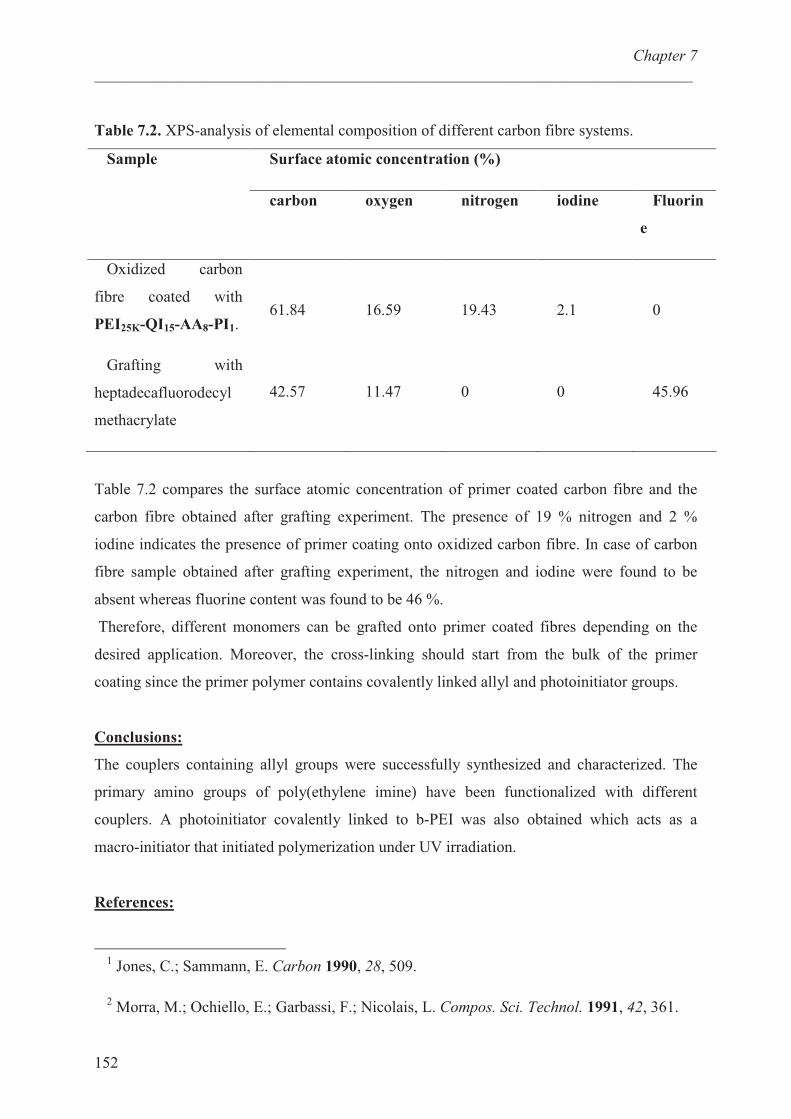
Chapter 7
___________________________________________________________________________
152
Table 7.2. XPS-analysis of elemental composition of different carbon fibre systems.
Surface atomic concentration (%) Sample
carbon oxygen nitrogen iodine Fluorin
e
Oxidized carbon
fibre coated with
PEI25K-QI15-AA8-PI1.
Grafting with
heptadecafluorodecyl
methacrylate
61.84
42.57
16.59
11.47
19.43
0
2.1
0
0
45.96
Table 7.2 compares the surface atomic concentration of primer coated carbon fibre and the
carbon fibre obtained after grafting experiment. The presence of 19 % nitrogen and 2 %
iodine indicates the presence of primer coating onto oxidized carbon fibre. In case of carbon
fibre sample obtained after grafting experiment, the nitrogen and iodine were found to be
absent whereas fluorine content was found to be 46 %.
Therefore, different monomers can be grafted onto primer coated fibres depending on the
desired application. Moreover, the cross-linking should start from the bulk of the primer
coating since the primer polymer contains covalently linked allyl and photoinitiator groups.
Conclusions:
The couplers containing allyl groups were successfully synthesized and characterized. The
primary amino groups of poly(ethylene imine) have been functionalized with different
couplers. A photoinitiator covalently linked to b-PEI was also obtained which acts as a
macro-initiator that initiated polymerization under UV irradiation.
References:
1 Jones, C.; Sammann, E. Carbon 1990, 28, 509.
2 Morra, M.; Ochiello, E.; Garbassi, F.; Nicolais, L. Compos. Sci. Technol. 1991, 42, 361.
Chapter 7
___________________________________________________________________________
153
3 Yuan, L. Y.; Chen, C. S.; Shyu, S. S.; Lai, J. Y. Compos. Sci. Technol. 1992, 45, 1.
4 Chapiro, C. A. Radiation Chemistry of PolymericSystems, Interscience 1962.
5 Sakurada, I.; Irada, Y.; Kawahara, T. Polym. Sci.Polym. Chem. Ed. 1 1973, 2329.
6 Nayak, P. L. Makromol. Chem. 1979, 80, 95.
7 Oster, G.; Shibata, O. J. Polym. Sci. 1957, 26,233.
8 Oster, G.; Oster, G. K.; Moroson, H. J. Polym. Sci. 1959, 34, 671.
9 Geacintov, N.; Stannett, V.; Abrahamson, E. W. Makrokol. Chem. 1960, 36, 52.
10 Geacintov, N.; Stannett, V.; Abrahamson, E. W.; Hermans, J. J. J. Appl. Polym. Sci.
1960, 3, 54.
11 Zhang, P. Y.; Ranby, B. J. Appl. Polym. Sci. 1990, 40, 1647.
12 Feng, Z. G.; Ranby, B. J. Angew. Makromol. Chem. 1992, 195, 17.
13 Ranby, B. J.; Gao, Z. M.; Hult, A.; Zhang, P. Y. Polymer Preprints (ACS) 1986, 27, 38.
14Ranby, B. J.; Gao, Z. M.; Hult, A.; Zhang, P. Y ACS Symposium Series 1988, 364, 168.
15 Moeller, M.; Beginn, U.; Keul, H.; Thomas, H. European Patent 2006 EP 1710282 A1
2006 1011.
16 Ubaghs, L.; Fricke, N.; Keul, H.; Höcker, H. Macromol. Rapid Commun. 2004, 25, 517.
17 Pasquier, N.; Keul, H.; Moeller, M. Designed Monomers and Polymers 2005, 8, 679.
18 Goel, V.; Beginn, U.; Mourran, A.; Möller, M. 2008, 41, 8187.
19 Kobayashi, S. Progress in Polymer Science 1990, 15, 751.
20 Idris, S. A.; Mkhatresh, O. A.; Heatley, F. Poly. Int. 2006, 55, 1040.
21 Nagalsdieck, R.; Mennicken, M.; Maier, B.; Keul, H.; Höcker, H. Macromolecules 2004,
37, 8923.
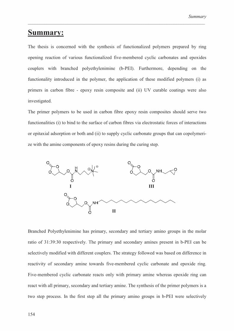
Summary
___________________________________________________________________________
154
Summary: The thesis is concerned with the synthesis of functionalized polymers prepared by ring
opening reaction of various functionalized five-membered cyclic carbonates and epoxides
couplers with branched polyethylenimine (b-PEI). Furthermore, depending on the
functionality introduced in the polymer, the application of these modified polymers (i) as
primers in carbon fibre - epoxy resin composite and (ii) UV curable coatings were also
investigated.
The primer polymers to be used in carbon fibre epoxy resin composites should serve two
functionalities (i) to bind to the surface of carbon fibres via electrostatic forces of interactions
or epitaxial adsorption or both and (ii) to supply cyclic carbonate groups that can copolymeri-
ze with the amine components of epoxy resins during the curing step.
Branched Polyethylenimine has primary, secondary and tertiary amino groups in the molar
ratio of 31:39:30 respectively. The primary and secondary amines present in b-PEI can be
selectively modified with different couplers. The strategy followed was based on difference in
reactivity of secondary amine towards five-membered cyclic carbonate and epoxide ring.
Five-membered cyclic carbonate reacts only with primary amine whereas epoxide ring can
react with all primary, secondary and tertiary amine. The synthesis of the primer polymers is a
two step process. In the first step all the primary amino groups in b-PEI were selectively
I
II
III

Summary
___________________________________________________________________________
155
modified with coupler I or II or both. In the next step the secondary amine in modified b-PEI
opens the epoxide ring present in the coupler III to obtain the desired functional polymers.
Due to structural similarity of the carbon fibre and graphite, highly oriented pyrolytihc
graphite (HOPG) was used as model substrate. In order to study the adsorption behaviour of
modified b-PEI’s onto HOPG different parameters were varied: (i) length of alkyl chain (C8,
14 and C16), (ii) the molar ratio of cationic/alkyl groups and (iii) molecular weight of b-PEI.
The adsorption behaviour of these polymers onto HOPG was studied by Scanning Force
Microscopy (SFM). Upon deposition on HOPG rod like structure was observed and their
confirmation was controlled by the surface coverage and by the two dimensional self-
assembly of aliphatic chains. The amount of adsorbed material was found to increase with the
length of the used alkyl chain and maximum adsorption was observed for the C16 modified b-
PEI. Furthermore, the degree of adsorption onto graphite decreased with the increase in
amount of quaternary ammonium groups in the polymer.
These primer coatings were applied to carbon fibre and interfacial adhesion between carbon
fibre and epoxy resin was demonstrated by well known Kelley Tyson Fragmentation test. The
use of primer coating increased the interfacial shear strength by 25 % with respect to unsized
fibre.
U.V. curable coatings prepared were also prepared based on b-PEI. These coatings can be
obtained in one step synthesis by polymer analogous reaction with different kind of functional
carbonates containing allyl groups with b-PEI.