Qt DtQuantum Dot-Cd ti PlConducting Polymer Hbid f … · Hbid f Ot l t i D iHybrids for...
23
Korea-US NanoForum 2010 ECC, Ewha Univ., Korea 2010. 4. 5-6 Q t Dt C d ti Pl Quantum Dot-Conducting Polymer H b id f Ot l t i D i Hybrids for Optoelectronic Devices 2010. 4. 5. Changhee Lee School of Electrical Engineering and Computer Science Seoul National Univ. [email protected] CHANGHEE LEE| Organic Semiconductor Lab. | Seoul National University CHANGHEE LEE| Organic Semiconductor Lab. | Seoul National University 1/23
Transcript of Qt DtQuantum Dot-Cd ti PlConducting Polymer Hbid f … · Hbid f Ot l t i D iHybrids for...

Korea-US NanoForum 2010ECC, Ewha Univ., Korea
2010. 4. 5-6
Q t D t C d ti P lQuantum Dot-Conducting Polymer
H b id f O t l t i D iHybrids for Optoelectronic Devices
2010. 4. 5.
Changhee LeeSchool of Electrical Engineering and Computer Science
Seoul National Univ. [email protected]
CHANGHEE LEE| Organic Semiconductor Lab. | Seoul National University CHANGHEE LEE| Organic Semiconductor Lab. | Seoul National University 1/23
Korea-US NanoForum 2010ECC, Ewha Univ., Korea
2010. 4. 5-6Contents
• Introduction of semiconductor Quantum dots
• Quantum Dot / Conducting Polymer Hybrid Material
• Light-Emitting Diodes Based on QD-Polymer Hybrid Materials
• Summary
CHANGHEE LEE| Organic Semiconductor Lab. | Seoul National University CHANGHEE LEE| Organic Semiconductor Lab. | Seoul National University 2/23

Korea-US NanoForum 2010ECC, Ewha Univ., Korea
2010. 4. 5-6Nanoparticle applications
• Quantum dotsQ– QDLEDs– Solar cells– Biomedicine• Magnetic nanoparticles– Biomedicine: MRI. Hyperthemia, Drug delivery• Metal nanoparticles– Biodetection (Au. Ag)– Electromagnetic shell (Fe, Ni, Co)– Nanofluid
QLED & Display
• Metal oxide nanoparticles– Dielectrics– Nanocomposite
- +
PEDOT PSSActive Layer
Al
Biomarkers
– Nanocoating PEDOT:PSSITO
SAIT
CHANGHEE LEE| Organic Semiconductor Lab. | Seoul National University CHANGHEE LEE| Organic Semiconductor Lab. | Seoul National University 3/23
A. P. Alivisatos, Science (1998)W. U. Huynh, J. J. Dittmer, A. P. Alivisatos,
Science, 295, 2425 (2002)NANOCO

Korea-US NanoForum 2010ECC, Ewha Univ., Korea
2010. 4. 5-6
F t QD LED OLED
Comparison of QD-LED and OLEDFeature QD-LED OLEDEfficiency Low High
Emission bandwidth(color saturation)
NarrowFWHM<30nm
BroadFWHM<50-100 nm
Color TunabilityExcellent:Change QD size
Low:Different emitter
Cost of EmitterLow: One procedure for all HighpRGB emitters
g
Manufacturing process Solution-basedVacuum deposition Solution-based
Large display area Yes Yes J. H. Kwak, Ph.D. Thesis (SNU, 2010)
Flexibility Yes Yes
CHANGHEE LEE| Organic Semiconductor Lab. | Seoul National University CHANGHEE LEE| Organic Semiconductor Lab. | Seoul National University 4/23
J. H. Kwak et al., SID 2010J. H. Kwak, Ph.D. Thesis (SNU, 2010)
Korea-US NanoForum 2010ECC, Ewha Univ., Korea
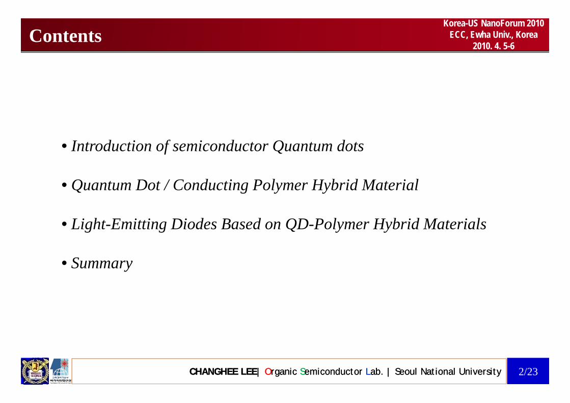
2010. 4. 5-6LEDs based on colloidal quantum dots
QD-LEDs
e injection
QDs
HTL
pcathode
ETLHTL
anode
cathodeLight• Size-tunable band-gaps (Color tunability)
• High PL quantum efficiency• Good photostability
N i i li idth (FWHM
h injection
• Narrow emission line widths (FWHM <30 nm)• Compatibility with solution processing methods
CHANGHEE LEE| Organic Semiconductor Lab. | Seoul National University CHANGHEE LEE| Organic Semiconductor Lab. | Seoul National University 5/23
e-h Recombination methods

Korea-US NanoForum 2010ECC, Ewha Univ., Korea
2010. 4. 5-6QD LEDs Tunable over the Entire Visible Spectrum
CHANGHEE LEE| Organic Semiconductor Lab. | Seoul National University CHANGHEE LEE| Organic Semiconductor Lab. | Seoul National University 6/23
Polina O. Anikeeva, Jonathan E. Halpert, Moungi G. Bawendi and Vladimir Bulovic (MIT), Nano Lett., 2009, 9 (7), pp 2532–2536

Korea-US NanoForum 2010ECC, Ewha Univ., Korea
2010. 4. 5-6Problems for low efficiency of colloidal QD-LEDs
Wid b d h llPoor charge carrier injection because • Wide energy band gap shell• Organic ligands• Surface traps
Poor charge carrier injection because1) QDs generally have an inorganic shell of a wide
bandgap material (e.g., CdS or ZnS) to increase
HIL/HTL
organic
photostability and improve emission quantum yields by passivating surface defects.
2) QDs are covered by a layer of organic ligands, organic
5~5.5 eV
QD
2) QDs are covered by a layer of organic ligands, which is needed during their growth and provides solubility in organic solvents to allow processing. H h i d i i l f 6.5~7.3 eV
1~2 eV gap
However, these organic and inorganic layers form a tunneling barrier for charge injection.
3) The valence bands of the QDs are generally shifted T i X ti i
) g yto lower energy compared to the highest occupied molecular orbital (HOMO) levels of commonly used organic hole injection layers This introduces
Top view X-section view
used organic hole-injection layers. This introduces significant energy barriers to hole injection.
4) Massive QD aggregation occurs in blend film of
CHANGHEE LEE| Organic Semiconductor Lab. | Seoul National University CHANGHEE LEE| Organic Semiconductor Lab. | Seoul National University 7/23
QDs and polymers Poor morphology

Korea-US NanoForum 2010ECC, Ewha Univ., Korea
2010. 4. 5-6Conducting Polymer - Nanoparticle Hybrid System
NanoparticleC d i l / b id
op c eConducting Polymer/NP Hybrid
• High extinction coefficient• High electron mobility• Band gap & position tunability• Solution process capability
PolymerSHSH
SH
• High extinction coefficient
S
SHSH
• High extinction coefficient• High hole mobility• Solution process capability• Patterning capability
• Efficient charge separation• Improved colloidal stability• Solution process capability
i bili
CHANGHEE LEE| Organic Semiconductor Lab. | Seoul National University CHANGHEE LEE| Organic Semiconductor Lab. | Seoul National University 8/23
• Patterning capability• Synthesis thru RAFT, ATRP, NMP
• Patterning capability

Korea-US NanoForum 2010ECC, Ewha Univ., Korea
2010. 4. 5-6Quantum Dot / Conducting Polymer Hybrid
SHm
NHO
n
SHN
Evidence of hybridization
poly(TPA)-b-cysteaminacrylate
* UV illumination (365 nm, 2 mW/cm2)
hhexane
dimetyhlformamide
CHANGHEE LEE| Organic Semiconductor Lab. | Seoul National University CHANGHEE LEE| Organic Semiconductor Lab. | Seoul National University 9/23
Matthias Zorn, Wan Ki Bae, Jeonghun Kwak, Hyemin Lee, Changhee Lee, Rudolf Zentel, Kookheon Char, ACS Nano 3 (5), 1063 (2009)

Korea-US NanoForum 2010ECC, Ewha Univ., Korea
2010. 4. 5-6
Q t D t / C d ti P l H b id
Comparison of QD/Polymer Hybrid and Blend• Quantum Dot / Conducting Polymer Hybrids
The thiol anchor groups in the CAA block replace the surface ligands (oleic acid) of QDs, leading to QD/conducting polymer
hybrid films.
* poly(para methyl triphenylamine-b-cysteamine acrylamide)
• Quantum Dot / Conducting Polymer Blends
The fluorinated block (PFP) ith l f(PFP) with low surface energy does not have
specific interactions with QDs, resulting in
QD/ d ti lQD/conducting polymer blend films.
* poly(para methyl triphenylamine-b-pentafluorophenole)
CHANGHEE LEE| Organic Semiconductor Lab. | Seoul National University CHANGHEE LEE| Organic Semiconductor Lab. | Seoul National University 10/23
Jeonghun Kwak, Wan Ki Bae, Matthias Zorn, Heeje Woo, Hyunsik Yoon, Jaehoon Lim, Sang Wook Kang, Stefan Weber, Hans-Jürgen Butt, Rudolf Zentel, Seonghoon Lee, Kookheon Char, Changhee Lee, Adv. Mater. 21 (48), 5022 (2009)

Korea-US NanoForum 2010ECC, Ewha Univ., Korea
2010. 4. 5-6Comparison of QD/Polymer Hybrid and Blend
Pristine QDs (OA)QD+polymer
blends
a. u
.)
QD/Polymer Hybridsblends
nten
sity
(a
PL In
PTPA-b-
Wavelength (nm)
400 450 500 550 600CAA
About 80 % of the PL intensity remains after grafting the QD surfaces with block copolymer
CHANGHEE LEE| Organic Semiconductor Lab. | Seoul National University CHANGHEE LEE| Organic Semiconductor Lab. | Seoul National University 11/23
copolymer.
Korea-US NanoForum 2010ECC, Ewha Univ., Korea
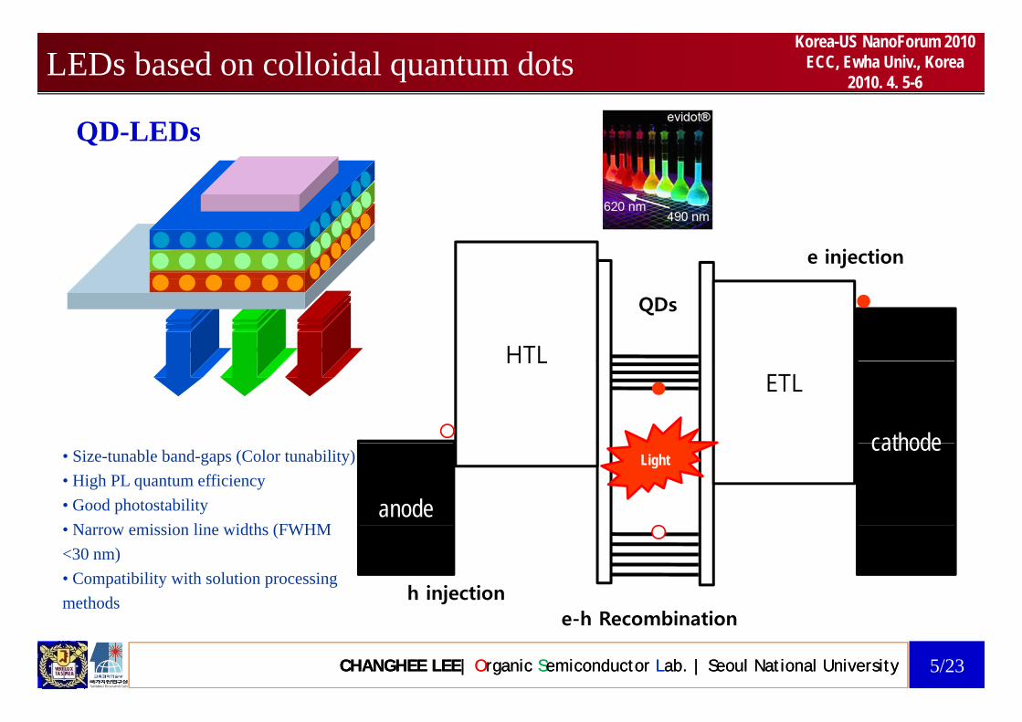
2010. 4. 5-6Comparison of QD/Polymer Hybrid and Blend
Hybrid Film
Blend Film
Fluorescent Optical Microscopy Optical Microscopy
* All films were fabricated by spin-coating
CHANGHEE LEE| Organic Semiconductor Lab. | Seoul National University CHANGHEE LEE| Organic Semiconductor Lab. | Seoul National University 12/23
coating.

Korea-US NanoForum 2010ECC, Ewha Univ., Korea
2010. 4. 5-6Comparison of QD/Polymer Hybrid and Blend
Hybrid Films TEM top view
QD 0.5 wt% QD 1.0 wt% QD 1.5 wt%
* All films were fabricated by spin-coating.
Blend FilmsQD 0.5 wt% QD 1.0 wt% QD 1.5 wt%
* Scale bars in the figure are 200 nm.
H b id d Bl d fil h d i diff
CHANGHEE LEE| Organic Semiconductor Lab. | Seoul National University CHANGHEE LEE| Organic Semiconductor Lab. | Seoul National University 13/23
Hybrid and Blend films show drastic differences.

Korea-US NanoForum 2010ECC, Ewha Univ., Korea
2010. 4. 5-6Comparison of QD/Polymer Hybrid and Blend
Hybrid Films TEM top view
QD 0.5 wt% QD 1.0 wt%
TEM cross-section view
QD 1.5 wt%
Blend FilmsQD 0.5 wt% QD 1.0 wt%
* Scale bars in the figure are 200 nm.
A i & h i i hi bl d fil
QD 1.5 wt%
CHANGHEE LEE| Organic Semiconductor Lab. | Seoul National University CHANGHEE LEE| Organic Semiconductor Lab. | Seoul National University 14/23
Aggregation & phase separation within blend films.
Korea-US NanoForum 2010ECC, Ewha Univ., Korea
2010. 4. 5-6
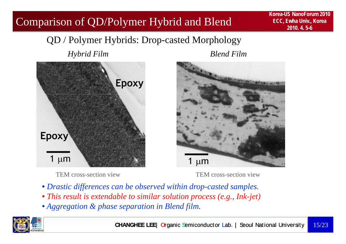
QD / Polymer Hybrids: Drop casted Morphology
Comparison of QD/Polymer Hybrid and BlendQD / Polymer Hybrids: Drop-casted Morphology
Hybrid Film Blend Film
TEM cross-section viewTEM cross-section view
• Drastic differences can be observed within drop-casted samples.• This result is extendable to similar solution process (e.g., Ink-jet)• A ti & h ti i Bl d fil
CHANGHEE LEE| Organic Semiconductor Lab. | Seoul National University CHANGHEE LEE| Organic Semiconductor Lab. | Seoul National University 15/23
• Aggregation & phase separation in Blend film.
Korea-US NanoForum 2010ECC, Ewha Univ., Korea
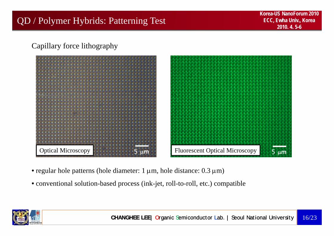
2010. 4. 5-6QD / Polymer Hybrids: Patterning Test
Capillary force lithography
Fluorescent Optical MicroscopyOptical Microscopy
• regular hole patterns (hole diameter: 1 μm hole distance: 0 3 μm)regular hole patterns (hole diameter: 1 μm, hole distance: 0.3 μm)
• conventional solution-based process (ink-jet, roll-to-roll, etc.) compatible
CHANGHEE LEE| Organic Semiconductor Lab. | Seoul National University CHANGHEE LEE| Organic Semiconductor Lab. | Seoul National University 16/23

Korea-US NanoForum 2010ECC, Ewha Univ., Korea
2010. 4. 5-6QD/Polymer hybrid films for efficient QD-LEDs
CHANGHEE LEE| Organic Semiconductor Lab. | Seoul National University CHANGHEE LEE| Organic Semiconductor Lab. | Seoul National University 17/23
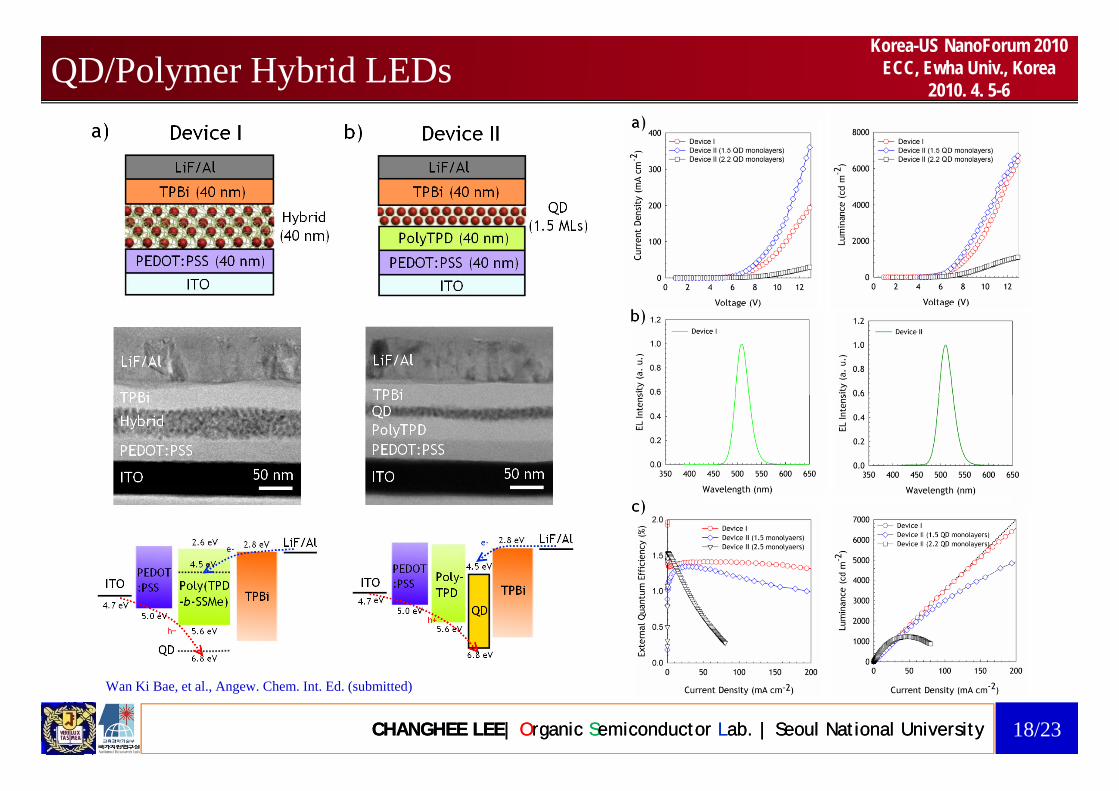
Korea-US NanoForum 2010ECC, Ewha Univ., Korea
2010. 4. 5-6QD/Polymer Hybrid LEDs
CHANGHEE LEE| Organic Semiconductor Lab. | Seoul National University CHANGHEE LEE| Organic Semiconductor Lab. | Seoul National University 18/23
Wan Ki Bae, et al., Angew. Chem. Int. Ed. (submitted)

Korea-US NanoForum 2010ECC, Ewha Univ., Korea
2010. 4. 5-6Multicolor QLEDs
Pixel size = 3.5 x 3.8 cm2QLED in Large Area
G5 G4/YG
Multicolored QLEDs
1 cm 1 cm
G4/RG4/O
1 cm 1 cm
G4/RG4/O
1 cm1 cm 1 cm
QLED with Strong EL EmissionQLED with Strong EL Emission
G5 G4/YG G4/RG4/O
CHANGHEE LEE| Organic Semiconductor Lab. | Seoul National University CHANGHEE LEE| Organic Semiconductor Lab. | Seoul National University 19/23

Korea-US NanoForum 2010ECC, Ewha Univ., Korea
2010. 4. 5-6
QD P l bl d P l /NP H b id
QD-Polymer Blend vs Polymer/NP HybridQD-Polymer blend Polymer/NP Hybrid
Polymer/NP hybrid
T i X ti i Top view X ti i
NP Polymer
Polymer/NP hybrid
Top view X-section view Top view X-section view
• Physical mixing of NPs & polymers• Massive QD aggregation• Poor morphology control
• Chemical binding btw NPs & polymers• Nanoscopic morphology control• Extensive process capability• Poor morphology control
• Surface states of NPs• Extensive process capability• Surface state passivation with polymers• Improved colloidal stability
Limited efficiency & poor reproducibility High efficiency & reliability!P. Alivisatos(U.C. Berkeley), R. Jenssen(Eindhoven)
CHANGHEE LEE| Organic Semiconductor Lab. | Seoul National University CHANGHEE LEE| Organic Semiconductor Lab. | Seoul National University 20/23
ed e c e cy & poo ep oduc b y High efficiency & reliability!Jeonghun Kwak, et al., Adv. Mater. 21 (48), 5022 (2009)

Korea-US NanoForum 2010ECC, Ewha Univ., Korea
2010. 4. 5-6Summary
• Quantum Dot / Conducting Polymer Hybrid Material- QD/conducting polymer hybrid materials have been prepared by grafting conducting polymer
with anchor group.
Quantum Dot / Conducting Polymer Hybrid Material
- Hybrid films show improved surface/bulk morphology and stability compared to QD/conducting
polymer composite films. p y p f
d d l hi h ffi i d d ffi i ll ff d hi h l i
• Light-Emitting Diodes Based on QD-Polymer Hybrid Materials
- reduced turn-on voltage, high efficiency, reduced efficiency roll-off and high color purity.
• Compatible with conventional solution/patterning process and Applicable to another l d h l ll h d doptoelectronic devices such as solar cells, photodiodes, etc.
CHANGHEE LEE| Organic Semiconductor Lab. | Seoul National University CHANGHEE LEE| Organic Semiconductor Lab. | Seoul National University 21/23
Jeonghun Kwak, et al., Adv. Mater. 21 (48), 5022 (2009) Wan Ki Bae, et al., Angew. Chem. Int. Ed. (submitted)

Korea-US NanoForum 2010ECC, Ewha Univ., Korea
2010. 4. 5-6Acknowledgements
Prof. Seonghoon Lee(School of Chemistry, SNU)
Prof. Kookheon Char (Dept. of Chemical Engineering, SNU)
Prof. Rudolf Zentel (Univ. of Mainz)
Dr. Wan ki Bae (SNU)
Dr. Jeonghun Kwak (SNU)
Mr. Donggu Lee (M.S. student, SNU)
Dr. Matthias Zorn (Univ. of Mainz)Brain Korea 21 Program (SNU/MEST)
Mr. Min Ki Nam (M.S. student, SNU)
Mr. Jaehoon Lim (M.S. student, SNU) International Research Training Group (IRTG)
CHANGHEE LEE| Organic Semiconductor Lab. | Seoul National University CHANGHEE LEE| Organic Semiconductor Lab. | Seoul National University 22/23

Korea-US NanoForum 2010ECC, Ewha Univ., Korea
2010. 4. 5-6
Th k h f iThank you very much for your attention.
CHANGHEE LEE| Organic Semiconductor Lab. | Seoul National University CHANGHEE LEE| Organic Semiconductor Lab. | Seoul National University 23/23