Multiplication Discussion 11.2. Multiplier Binary Multiplication 4 x 4 Multiplier.

Pulse Multiplication In Autotransformer Based … 191
JPE 7-3-2
Pulse Multiplication in Autotransformer Based AC-DC Converters using a Zigzag Connection
Bhim Singh* and Sanjay Gairola†
†*Department of Electrical Engineering, Indian Institute of Technology, Delhi, New-Delhi, India
ABSTRACT
This paper deals with pulse multiplication in zigzag connected autotransformer based 12-pulse AC-DC converters feeding vector controlled induction motor drives (VCIMD) for improving the power quality at the point of common coupling (PCC) without using a Zero-Sequence-Blocking-Transformer (ZSBT). The proposed 24-pulse AC-DC converter is based on the principle of DC ripple re-injection technique for pulse multiplication and harmonic mitigation. The design of the autotransformer is carried out for the proposed AC-DC converter and the effect of load variation on VCIMD is also studied to demonstrate the effectiveness of the proposed AC-DC converter. Test results from a laboratory developed prototype, along with simulated results, are presented to validate the design and model of the proposed 24-pulse AC-DC converter.
Keywords: Autotransformer, Multipulse AC-DC converter, Pulse multiplication, Power quality, VCIMD
1. Introduction
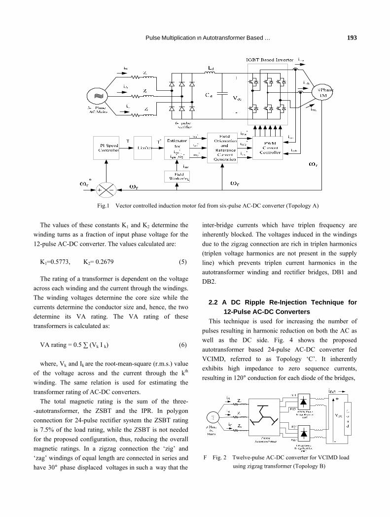
The most common industrial motor is an induction motor and its speed control is achieved by employing a voltage source inverter for generating a variable frequency supply. Variable frequency induction motor drives (VFIMDs) are used in numerous applications such as heating, ventilating and air conditioning (HVAC) systems, blowers, fans, cement industries, etc. These VFIMDs are controlled in vector control mode [1] due to their inherent advantages. These are generally fed from a 6-pulse diode bridge AC-DC converter, which injects current harmonics into AC mains. Fig. 1 shows such a 6-pulse diode bridge
rectifier fed vector controlled induction motor drive (Topology ‘A’). These harmonics cause increased losses for the customer and utility power system components, de-rating of distribution transformers and failure of capacitor banks. These current harmonics, while flowing through source impedance, result in voltage distortion at the point of common coupling (PCC), thereby affecting neighboring consumers. Stringent power quality regulation and strict limits on current and voltage distortion have been imposed by various standards such as IEC 61000-3-2 [2] and IEEE 519-1992 [3]. These needs to improve power quality have attracted the attention of researchers.
Power quality can be improved by employing passive or active filters. Passive filters cause additional losses, need additional floor area and are complex in design as their performance is affected by changes in frequency.
Manuscript received Nov. 11, 2006, revised March 12, 2007 †Corresponding Author: [email protected]
Tel: +91-9810917448, Fax: +91-11226581606, IIT *Department of Electrical Engineering, Indian Institute of Technology
brought to you by COREView metadata, citation and similar papers at core.ac.uk
provided by Publications of the IAS Fellows

192 Journal of Power Electronics, Vol. 7, No. 3, July 2007 Similarly, active filters are also costly and complex, and have ratings comparable to the load rating. The use of multipulse AC-DC converters is one such technique for harmonic mitigation and is found to be rugged and reliable. This method uses two or more bridge converters, where the harmonics generated by one converter are cancelled by another converter by a proper phase shift. Different topologies of 12-pulse AC-DC converters have been reported in the literature for harmonic mitigation [4–8], but these configurations also fail to comply with the above mentioned power quality standards. Increasing the number of pulses results in further improvement in various power quality indices, but also results in the additional cost of different converters and increased system complexity. To achieve similar performance in terms of various power quality indices at a reduced cost, the DC ripple re-injection technique [9–11] is a viable and cost effective solution.
However, it must be noted that in all these autowound transformer based rectifiers employing ripple reinjection techniques, a Zero-Sequence-Blocking-Transformer (ZSBT) of significant rating (7.5% of DC load power rating) is required. The role of a ZSBT here is to prevent circulating currents between two converters and, thus, prevent unequal conduction of upper and lower diodes in the legs of the converter bridges. This paper presents an autotransformer based 24-pulse AC-DC converter that does not require a ZSBT when the DC ripple re-injection technique is used for pulse doubling. The DC ripple re-injection technique used for harmonic mitigation requires two additional diodes along with a suitable tapped interphase reactor for increasing the number of pulses. A set of tabulated results giving a comparison of different power quality indices such as total harmonic distortion (THD) and crest factor of AC main current (CF), power factor (PF), displacement factor (DPF) and distortion factor (DF), and THD of the supply voltage at PCC is presented for a VCIMD fed from an existing 6-pulse AC-DC converter, 12-pulse AC-DC converter and proposed 24-pulse AC-DC converter. A laboratory prototype of the proposed 24-pulse AC-DC converter is developed to validate its design and simulation model.
2. A Zigzag Transformer Based 24-Pulse AC-DC Converter
The phase shift required for proper harmonic elimination in multipulse AC-DC converters is given by [4]:
Phase shift = 60°/(Number of six-pulse converters ) (1)
For achieving 12-pulse AC-DC conversion, the phase shift between the two sets of voltages may be either of 0° and 30° or ±15° with respect to the supply voltages. Fig. 2 shows the schematic diagram of a zigzag autotransformer based 12-pulse AC-DC converter [8] with a phase shift of +15° and −15°, referred to as Topology ‘B’. Similarly, Fig. 3 shows the transformer winding arrangement and its connection to supply and diode bridge converters DB1 and DB2 along with the phasor diagram. Fig. 4 shows the schematic diagram of a zigzag autotransformer based 24- pulse AC-DC converter with a diode tapped interphase reactor (IPR), referred to as Topology ‘C’.
2.1 Design of the Autotransformer for a
12-Pulse AC-DC Converter without ZSBT for Pulse Doubling
In the proposed converter system, three-phase supply voltages are fed to the autotransformer windings connected in zigzag fashion, as shown in Fig. 3(a). It uses four auxiliary windings per phase. From these voltages, two sets of 3-phase voltages (phase shifted through +15° and −15°) are produced. The number of turns required for +15° and −15° phase shift is calculated as follows. Fig. 3(a) shows the schematic diagram of the zigzag-connected autotransformer for a 12-pulse AC-DC converter. The number of turns for its windings is determined as a function of the input phase voltage, VA using the following relations.
Consider the following set of three-phase supply voltage applied to the input of autotransformer as:
A S B S C S
AB S BC S CA S
V V 0 , V V 120 , V V 120
V 3V 30 , V 3V 90 , V 3V 150
= ∠ ° = ∠− ° = ∠ °
= ∠ ° = ∠− ° = ∠ ° (2)
Moreover, from Fig. 3(b), the output voltages of this configuration are expressed as:
BC2CAAB1A1 VK)V(VKV −−= (3)
BC2CAAB1A2 VK)V(VKV +−= (4)
Pulse Multiplication In Autotransformer Based … 193
The values of these constants K1 and K2 determine the winding turns as a fraction of input phase voltage for the 12-pulse AC-DC converter. The values calculated are:
K1=0.5773, K2= 0.2679 (5)
The rating of a transformer is dependent on the voltage across each winding and the current through the windings. The winding voltages determine the core size while the currents determine the conductor size and, hence, the two determine its VA rating. The VA rating of these transformers is calculated as:
VA rating = 0.5 ∑ (Vk I k) (6) where, Vk and Ik are the root-mean-square (r.m.s.) value
of the voltage across and the current through the kth winding. The same relation is used for estimating the transformer rating of AC-DC converters.
The total magnetic rating is the sum of the three- -autotransformer, the ZSBT and the IPR. In polygon connection for 24-pulse rectifier system the ZSBT rating is 7.5% of the load rating, while the ZSBT is not needed for the proposed configuration, thus, reducing the overall magnetic ratings. In a zigzag connection the ‘zig’ and ‘zag’ windings of equal length are connected in series and have 30° phase displaced voltages in such a way that the
inter-bridge currents which have triplen frequency are inherently blocked. The voltages induced in the windings due to the zigzag connection are rich in triplen harmonics (triplen voltage harmonics are not present in the supply line) which prevents triplen current harmonics in the autotransformer winding and rectifier bridges, DB1 and DB2.
2.2 A DC Ripple Re-Injection Technique for
12-Pulse AC-DC Converters This technique is used for increasing the number of
pulses resulting in harmonic reduction on both the AC as well as the DC side. Fig. 4 shows the proposed autotransformer based 24-pulse AC-DC converter fed VCIMD, referred to as Topology ‘C’. It inherently exhibits high impedance to zero sequence currents, resulting in 120° conduction for each diode of the bridges,
Fig.1 Vector controlled induction motor fed from six-pulse AC-DC converter (Topology A)
F Fig. 2 Twelve-pulse AC-DC converter for VCIMD load using zigzag transformer (Topology B)
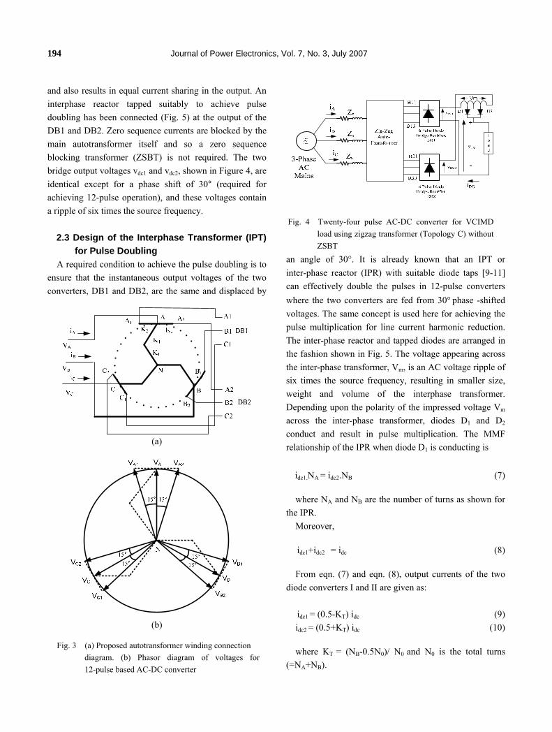
194 Journal of Power Electronics, Vol. 7, No. 3, July 2007 and also results in equal current sharing in the output. An interphase reactor tapped suitably to achieve pulse doubling has been connected (Fig. 5) at the output of the DB1 and DB2. Zero sequence currents are blocked by the main autotransformer itself and so a zero sequence blocking transformer (ZSBT) is not required. The two bridge output voltages vdc1 and vdc2, shown in Figure 4, are identical except for a phase shift of 30° (required for achieving 12-pulse operation), and these voltages contain a ripple of six times the source frequency.
2.3 Design of the Interphase Transformer (IPT)
for Pulse Doubling A required condition to achieve the pulse doubling is to
ensure that the instantaneous output voltages of the two converters, DB1 and DB2, are the same and displaced by
an angle of 30°. It is already known that an IPT or inter-phase reactor (IPR) with suitable diode taps [9-11] can effectively double the pulses in 12-pulse converters where the two converters are fed from 30° phase -shifted voltages. The same concept is used here for achieving the pulse multiplication for line current harmonic reduction. The inter-phase reactor and tapped diodes are arranged in the fashion shown in Fig. 5. The voltage appearing across the inter-phase transformer, Vm, is an AC voltage ripple of six times the source frequency, resulting in smaller size, weight and volume of the interphase transformer. Depending upon the polarity of the impressed voltage Vm across the inter-phase transformer, diodes D1 and D2 conduct and result in pulse multiplication. The MMF relationship of the IPR when diode D1 is conducting is
idc1.NA = idc2.NB (7)
where NA and NB are the number of turns as shown for the IPR.
Moreover,
idc1+idc2 = idc (8)
From eqn. (7) and eqn. (8), output currents of the two diode converters I and II are given as:
idc1 = (0.5-KT) idc (9) idc2 = (0.5+KT) idc (10)
where KT = (NB-0.5N0)/ N0 and N0 is the total turns (=NA+NB).
Fig. 4 Twenty-four pulse AC-DC converter for VCIMD
load using zigzag transformer (Topology C) without ZSBT
(a)
(b)
Fig. 3 (a) Proposed autotransformer winding connection
diagram. (b) Phasor diagram of voltages for 12-pulse based AC-DC converter

Pulse Multiplication In Autotransformer Based … 195
Similarly, the MMF relationships can be written for the case when diode D2 is conducting.
idc1 = (0.5-KT) idc (11) idc2 = (0.5+KT) idc (12)
Therefore, depending on the polarity of voltage Vm, the
magnitudes of the converter output currents are modulated and this changes the shape of the rectifier input currents and, thereby, doubles the pulses. The turn ratio of the interphase transformer for suppressing the 19th and 21st harmonics is given as: KT = 0.2457. The design parameters of the IPR are given in the Appendix.
3. MATLAB Based Simulation
The proposed AC-DC converter feeding VCIMD is simulated in the MATLAB environment, along with the Simulink and Power System Blockset (PSB) toolboxes. Fig. 6a shows the MATLAB model of the proposed AC-DC converter along with VCIMD to improve various power quality indices. The main autotransformer model is shown in Fig. 6b. The VCIMD consists of a 10 hp, 415 V induction motor drive (detailed data are given in the Appendix) controlled using the indirect vector control technique[1]. The source impedance has been kept at a practical value of 3% in all the simulations. The load is varied on the VCIMD to study its effect on various power quality indices. The results are tabulated in Table I and II and waveforms are shown in Figs. 7-11.
4. Experimentation
To validate the design procedure and simulation model,
a prototype of the proposed autotransformer based 24-pulse AC-DC converter, as shown in Fig. 3, has been developed in the laboratory. Three single-phase multiwinding transformers have been designed and wound in the laboratory to develop the proposed autotransformer. The design details of the same are given in the Appendix. Based on the voltage across different windings, the number of turns are calculated and based on the current flowing through different windings, the gauge of the wire is calculated. Similarly, an interphase transformer of small rating has been designed and developed (details are given in the Appendix). The experiments have been carried out at a three-phase line voltage of 415 V AC input with an equivalent resistive load.
These test results are given in Table III. The experimental results have been recorded using a Fluke power analyzer model 43B on the developed prototype of the 24-pulse AC-DC converter and shown in Figs. 12-13.
Fig. 6(a) MATLAB model of 24-pulse AC-DC converter with VCIMD load
Fig. 6(b) MATLAB model of auto-transformer for the 12-pulse and 24-pulse AC-DC converter simulation
Fig. 5 Tapped interphase reactor circuit
5. Results and Discussion
196 Journal of Power Electronics, Vol. 7, No. 3, July 2007
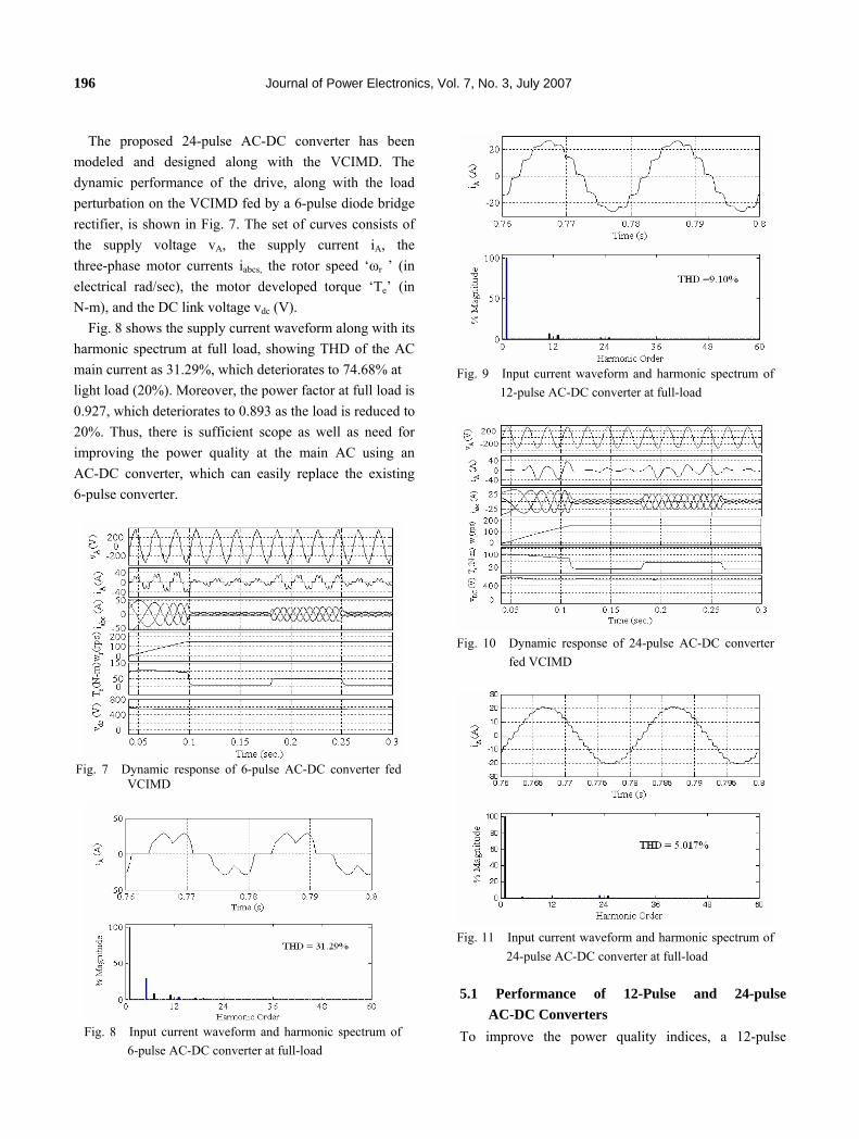
The proposed 24-pulse AC-DC converter has been modeled and designed along with the VCIMD. The dynamic performance of the drive, along with the load perturbation on the VCIMD fed by a 6-pulse diode bridge rectifier, is shown in Fig. 7. The set of curves consists of the supply voltage vA, the supply current iA, the three-phase motor currents iabcs, the rotor speed ‘ωr ’ (in electrical rad/sec), the motor developed torque ‘Te’ (in N-m), and the DC link voltage vdc (V).
Fig. 8 shows the supply current waveform along with its harmonic spectrum at full load, showing THD of the AC main current as 31.29%, which deteriorates to 74.68% at light load (20%). Moreover, the power factor at full load is 0.927, which deteriorates to 0.893 as the load is reduced to 20%. Thus, there is sufficient scope as well as need for improving the power quality at the main AC using an AC-DC converter, which can easily replace the existing 6-pulse converter.
5.1 Performance of 12-Pulse and 24-pulse AC-DC Converters
To improve the power quality indices, a 12-pulse
Fig. 9 Input current waveform and harmonic spectrum of 12-pulse AC-DC converter at full-load
Fig. 10 Dynamic response of 24-pulse AC-DC converter fed VCIMD
Fig. 11 Input current waveform and harmonic spectrum of 24-pulse AC-DC converter at full-load
Fig. 7 Dynamic response of 6-pulse AC-DC converter fed VCIMD
Fig. 8 Input current waveform and harmonic spectrum of 6-pulse AC-DC converter at full-load

Pulse Multiplication In Autotransformer Based … 197
AC-DC converter [8] fed VCIMD has been modeled and simulated. The THD of supply current at full load in Topology ‘B’ is observed to be 9.10% as shown in Fig. 9, whereas the power factor under this condition is 0.985, as shown in Table I, thus not complying with IEEE Standard 519 [3]. However, the rating of the magnetics is 26.73%, as shown in Table IV.
Fig. 10 shows the dynamic performance of the proposed 24-pulse AC-DC converter (Topology ‘C’) at starting and load perturbation. The supply current waveform at full load, along with its harmonic spectrum, is shown in Fig. 11 for Topology ‘C’, which shows that the THD of AC mains current is 5.01%, and the power factor obtained is 0.996. Under light load conditions, the THD of the AC main current is 6.384% and the power factor is 0.996. Table I shows the effect of load variation on the VCIMD to study various power quality indices. It shows that the proposed AC-DC converter is able to perform satisfactorily under load variation on VCIMD with almost unity power factor in the wide operating range of the drive, and THD of supply current always less than 8%. This is within the IEEE Standard 519 [3] limits. A comparison of different power quality indices of a VCIMD fed from different AC-DC converters is shown in Table II, which shows the improvement in these indices with the proposed AC-DC converter.
5.2 Experimental Validation For experimental validation of the design and
simulation model, a laboratory prototype of the proposed 24-pulse AC-DC converter is developed with details given in the previous section and the Appendix. Various tests are conducted on this developed converter, and test results are given in Table III and Figs. 12-13. Figs.12-13 show the tests results of the AC main current waveforms along with its harmonic spectrum at full load. These test and simulated results show a close agreement among them. The experimental results show the THD of the AC main current at full load as 5.2%, displacement factor of 1.00 and power factor near unity, thus confirming the 24-pulse converter behavior of the proposed AC-DC converter. In comparison to the magnetics rating of differential delta [9], polygon[10] and fork[11] connection based AC-DC converters (total magnetic ratings given as 32.15%, 28.8%
and 32.84% respectively) the proposed AC-DC converter rating (28.16%) is less and a ZSBT is also not required.
6. Conclusions
The design and model of an autotransformer based 24-pulse AC-DC converter with a VCIMD load, which needs only two additional diodes along with a suitably tapped inductor, has been developed and validated by employing pulse multiplication through a DC ripple
Fig. 12 Test result for 24-pulse non-isolated zigzag transformer
based AC-DC converter at 1.51kW load.
Fig. 13 Test result for 24-pulse non-isolated zigzag transformer
based AC-DC converter at 7.56kW load
198 Journal of Power Electronics, Vol. 7, No. 3, July 2007
re-injection technique in existing 12-pulse AC-DC converters. The proposed converter doesn’t use ZSBT, thereby decreasing the component count and, thus, increasing the reliability of the converter. The proposed 24-pulse AC-DC converter has resulted in a reduction in the rating of the magnetics, leading to a savings in the overall cost of the drive. The required level of THD and the crest factor of the AC main current has been achieved at almost close to unity power factor in the wide operating range of the drive.
Appendix
1. Motor and controller specifications: Three-phase squirrel cage induction motor −10 hp (7.5
kW), 3-phase, 4-pole, Y-connected, 415 V, 50 Hz, Rs = 1.0 ohms, Rr = 0.76 ohms, Xls = 0.77 ohms, Xlr = 0.77 ohms, Xm = 18.84 ohms, J = 0.1 kg-m2.
PI controller: Kp = 25, Ki = 4.5 DC link parameters: Ld = 0.002 H, Cd = 3200 µF.
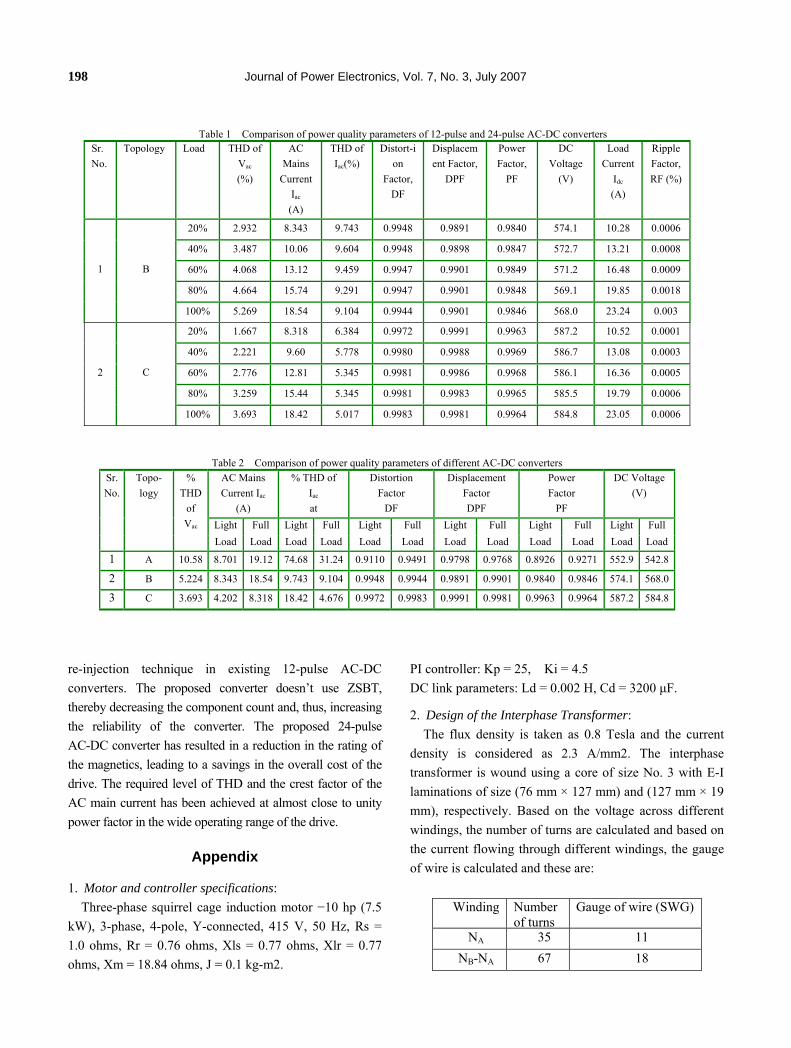
2. Design of the Interphase Transformer: The flux density is taken as 0.8 Tesla and the current
density is considered as 2.3 A/mm2. The interphase transformer is wound using a core of size No. 3 with E-I laminations of size (76 mm × 127 mm) and (127 mm × 19 mm), respectively. Based on the voltage across different windings, the number of turns are calculated and based on the current flowing through different windings, the gauge of wire is calculated and these are:
Winding Number
of turnsGauge of wire (SWG)
NA 35 11 NB-NA 67 18
Table 1 Comparison of power quality parameters of 12-pulse and 24-pulse AC-DC converters Sr. No.
Topology Load THD of Vac (%)
AC Mains
Current Iac (A)
THD of Iac(%)
Distort-ion
Factor, DF
Displacement Factor,
DPF
Power Factor,
PF
DC Voltage
(V)
Load Current
Idc (A)
Ripple Factor, RF (%)
20% 2.932 8.343 9.743 0.9948 0.9891 0.9840 574.1 10.28 0.0006
40% 3.487 10.06 9.604 0.9948 0.9898 0.9847 572.7 13.21 0.0008
60% 4.068 13.12 9.459 0.9947 0.9901 0.9849 571.2 16.48 0.0009
80% 4.664 15.74 9.291 0.9947 0.9901 0.9848 569.1 19.85 0.0018
1 B
100% 5.269 18.54 9.104 0.9944 0.9901 0.9846 568.0 23.24 0.003
20% 1.667 8.318 6.384 0.9972 0.9991 0.9963 587.2 10.52 0.0001
40% 2.221 9.60 5.778 0.9980 0.9988 0.9969 586.7 13.08 0.0003
60% 2.776 12.81 5.345 0.9981 0.9986 0.9968 586.1 16.36 0.0005
80% 3.259 15.44 5.345 0.9981 0.9983 0.9965 585.5 19.79 0.0006
2 C
100% 3.693 18.42 5.017 0.9983 0.9981 0.9964 584.8 23.05 0.0006
Table 2 Comparison of power quality parameters of different AC-DC converters Sr. No.
Topo- logy
AC Mains Current Iac
(A)
% THD of Iac at
Distortion Factor
DF
Displacement Factor DPF
Power Factor
PF
DC Voltage(V)
Light Full Light Full Light Full Light Full Light Full Light Full
% THD
of Vac
Load Load Load Load Load Load Load Load Load Load Load Load
1 A 10.58 8.701 19.12 74.68 31.24 0.9110 0.9491 0.9798 0.9768 0.8926 0.9271 552.9 542.8
2 B 5.224 8.343 18.54 9.743 9.104 0.9948 0.9944 0.9891 0.9901 0.9840 0.9846 574.1 568.0
3 C 3.693 4.202 8.318 18.42 4.676 0.9972 0.9983 0.9991 0.9981 0.9963 0.9964 587.2 584.8

Pulse Multiplication In Autotransformer Based … 199
3. Design of the Autotransformer: Autotransformer rating 2.684 kVA (26.44%) Interphase transformer 0.175 kVA. (1.72%) Transformer design details:
Flux Density: 0.8Tesla, Current Density: 2.3A/mm2, Core size: No. 7B E-Laminations: Length=190mm, Width=124mm I-Laminations: Length=190mm, Width= 32mm Area of cross-section of core=48.76cm2 (6.40 cm X 7.62cm)
Autotransformer winding details- Winding Voltage
Number of turns
Gauge of wire (SWG)
K1*VA 241 22 K2 *VA 108 18
4. Derivations for kVA ratings of transformers:
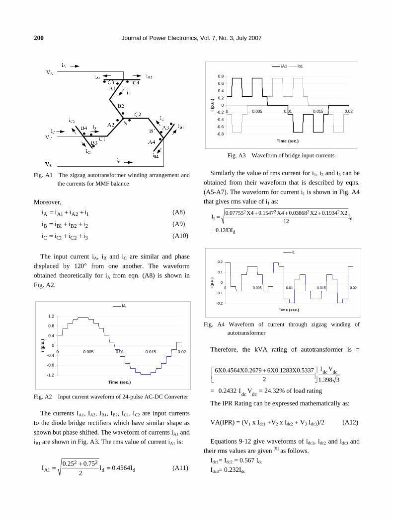
The autotransformer employed for the 24-pulse AC-DC converter is redrawn in Fig, A1 and various currents are marked for estimating its power rating. The MMF balance equations for the A, B and C phases of the autotransformer are:
1 1 3 2 B2 B1K (i i ) K (i i ) 0− + − = (A1)
1 2 1 2 C2 C1K (i i ) K (i i ) 0− + − = (A2)
1 3 2 2 A2 A1K (i i ) K (i i ) 0− + − = (A3)
Also 1 2 3i i i 0+ + = (A4)
The equations A1-A4 give the value of currents i1 to i3 as:
21 B1 B 2 C 2 C1
1
Ki (i i i i )
3K= − + − (A5)
22 C1 C 2 A 2 A1
1
Ki (i i i i )
3K= − + − (A6)
23 A1 A 2 B2 B1
1
Ki (i i i i )
3K= − + − (A7)
Table 3 Comparison of power quality parameters of hardware implementation obtained for 12-pulse and 24-pulse AC-DC converters Sr. No.
Topology Input Power (kW)
THD of Vs (%)
AC Mains Current Is (A)
THD of Is (%)
Crest Factor,CF
Displace-ment
Factor, DPF
Power Factor,
PF
DC Voltage
(V)
Load Current Idc (A)
Load (kW)
1.51 1.0 2.12 13.3 1.4 1.00 0.99 573.0 2.60 1.48 2.17 1.1 3.04 12.1 1.4 1.00 0.99 570.9 3.77 2.15 3.10 1.1 4.36 11.8 1.4 1.00 0.99 570.0 5.34 3.04 4.05 1.1 5.68 11.5 1.4 1.00 0.99 567.4 6.93 3.93 5.18 1.1 7.27 11.2 1.4 1.00 0.99 566.2 8.84 5.01 5.98 1.1 8.41 11.1 1.4 1.00 0.99 564.3 10.01 5.65 6.88 1.1 9.63 11.0 1.4 1.00 0.99 562.4 11.46 6.44
1 B
7.64 1.1 10.83 10.7 1.4 1.00 0.99 561.2 12.24 6.87 1.51 1.0 2.138 7.7 1.4 0.99 0.99 586.6 2.537 1.49 2.08 0.8 2.939 7.7 1.4 1.00 0.99 585.1 3.505 2.04 3.11 0.9 4.358 6.0 1.4 1.00 0.99 580.5 5.292 3.07 4.18 0.9 5.93 5.6 1.4 1.00 0.99 579.0 7.190 4.13 5.02 0.9 7.05 5.3 1.4 1.00 0.99 577.5 8.57 4.95 5.96 0.9 8.33 5.3 1.4 1.00 0.99 575.5 10.14 5.83 7.03 0.9 9.88 5.3 1.4 1.00 0.99 572.3 12.02 6.88
2 C
7.64 0.9 10.59 5.2 1.4 1.00 0.99 570.5 12.89 7.36
Table 3 Comparison of active-magnetic power ratings in different AC-DC converters Sr. No. Topology Main Transformer
rating (% of load) Interphase transformer
rating (% of load} Total magnetic rating
(% of load) 1 12-pulse 19.31 7.42 26.73 2 24-pulse 26.44 1.72 28.16
200 Journal of Power Electronics, Vol. 7, No. 3, July 2007
Fig. A1 The zigzag autotransformer winding arrangement and
the currents for MMF balance Moreover,
A A1 A2 1i i i i= + + (A8)
B B1 B2 2i i i i= + + (A9)
C C1 C2 3i i i i= + + (A10)
The input current iA, iB and iC are similar and phase
displaced by 120° from one another. The waveform obtained theoretically for iA from eqn. (A8) is shown in Fig. A2.
-1.2
-0.8
-0.4
0
0.4
0.8
1.2
0 0.005 0.01 0.015 0.02
Time (sec.)
i (p.
u.)
iA
Fig. A2 Input current waveform of 24-pulse AC-DC Converter
The currents IA1, IA2, IB1, IB2, IC1, IC2 are input currents to the diode bridge rectifiers which have similar shape as shown but phase shifted. The waveform of currents iA1 and iB1 are shown in Fig. A3. The rms value of current iA1 is:
2 2A1 d d
0.25 0.75I I 0.4564I2+= = (A11)
-0.8
-0.6
-0.4
-0.2
0
0.2
0.4
0.6
0.8
0 0.005 0.01 0.015 0.02
Time (sec.)
i (p.
u.)
iA1 ib1
Fig. A3 Waveform of bridge input currents
Similarly the value of rms current for i1, i2 and i3 can be
obtained from their waveform that is described by eqns. (A5-A7). The waveform for current i1 is shown in Fig. A4 that gives rms value of i1 as:
2 2 2 21 d
d
0.07755 X4 0.1547 X4 0.03868 X2 0.1934 X2I I12
0.1283I
+ + +=
=
-0.2
-0.1
0
0.1
0.2
0 0.005 0.01 0.015 0.02
Time (sec.)
i (p.
u.)
i1
Fig. A4 Waveform of current through zigzag winding of
autotransformer
Therefore, the kVA rating of autotransformer is =
dc dcI V6X0.4564X0.2679 6X0.1283X0.53372 1.398 3+⎡ ⎤
⎢ ⎥⎣ ⎦
= dc dc0.2432 I V = 24.32% of load rating
The IPR Rating can be expressed mathematically as:
VA(IPR) = (V1 x Idc1 +V2 x Idc2 + V3 Idc3)/2 (A12)
Equations 9-12 give waveforms of idc1, idc2 and idc3 and their rms values are given [9] as follows.
Idc1= Idc2 = 0.567 Idc Idc3= 0.232Idc

Pulse Multiplication In Autotransformer Based … 201
The rms voltage across IPR is due to the conduction of the positive and negative group of diodes in two diode bridges. The difference in the voltage at positive terminals of the two bridges is triangular with frequency twelve times the supply frequency. Its rms value is determined as:
T2m m
0
122LL
0
dc
1V v dtT
12 2 2V sin t d( t)1 3
0.0814 V
π
= ∫
⎛ ⎞⎛ ⎞= ⎜ ω ⎟ ω⎜ ⎟∫ ⎜ ⎟⎜ ⎟π +⎝ ⎠⎝ ⎠
=
(A13)
The voltages across the IPR sections can be written [9] in
terms of the voltage Vm as
1 2 A
m m A B
V V N0.2543
V V N N= = =
+ (A14)
3 B A
m A B
V N N0.4914
V N N−
= =+
(A15)
Therefore, the rms values of V1, V2, V3 are given as
V1=V2=0.2543Vm=0.021Vdc V3=0.4914Vm=0.04Vdc
VA rating of IPR is: =(0.021x0.567+0.021x0.567+0.04x0.232)Vdc Idc/2 =0.0165Pdc =1.65% of load rating
Therefore, theoretically the total magnetic rating of the proposed configuration is: 0.2432Pdc+0.0165Pdc= 25.97% of load power.
References
[1] P. Vas, Sensorless Vector and Direct Torque Control,
Oxford University Press, 1998. [2] Limits for Harmonic Current Emissions, International
Electrotechnical Commission Standard 61000-3-2, 2004. [3] IEEE Guide for Harmonic Control and Reactive
Compensation of Static Power Converters, IEEE Standard 519-1992.
[4] D. A. Paice, Power Electronic Converter Harmonics: Multipulse Methods for Clean Power, New York: IEEE
Press, 1996. [5] Bin Wu, High-Power Converters and AC Drives, IEEE
Press, Wiley-Interscience, 2006. [6] S. Choi, P. N. Enjeti, and I. J. Pitel, “Polyphase
transformer arrangements with reduced kVA capacities for harmonic current reduction in rectifier type utility interface”, IEEE Trans. on Power Electronics, Vol. 11, No. 5, pp. 680–689, September 1996.
[7] P. W. Hammond, “Autotransformer”, U.S. Patent No. 5619407, April 8, 1997.
[8] D. W. Owens, “Autotransformer for Use with Multiple Phase Rectifiers”, US Patent 7049921, May 23, 2006.
[9] S. Choi, B. S. Lee, and P. N. Enjeti, “New 24-pulse diode rectifier systems for utility interface of high power AC motor drives”, IEEE Trans. on Industry Applications, Vol. 33, No. 2, pp. 531–541, March/April 1997.
[10] B. Singh, G. Bhuvaneswari, V. Garg, “Power-quality improvements in vector-controlled induction motor drive employing pulse multiplication in AC-DC converters”, IEEE Trans. on Power Delivery, vol. 21 no. 3, pp. 1578 – 1586, July 2006,
[11] B. Singh, G. Bhuvaneswari, V. Garg, “24-Pulse AC-DC Converter for Power Quality Improvement in Vector Controlled Induction Motor Drives”, Electric Power Systems and Components, vol. 34, no. 10, pp. 1077 - 1098, October 2006.
Bhim Singh was born in Rahamapur, U. P., India in 1956. He received his B. E. (Electrical) degree from the University of Roorkee, India in 1977 and his M. Tech. and Ph. D. degrees from the Indian Institute of Technology (IIT), New-Delhi, in 1979 and
1983, respectively. In 1983, he joined as a Lecturer and in 1988 became a Reader in the Department of Electrical Engineering, University of Roorkee. In December 1990, he joined as an Assistant Professor, became an Associate Professor in 1994 and full Professor in 1997 at the Department of Electrical Engineering, IIT Delhi. His fields of interest include power electronics, electrical machines and drives, active filters, static VAR compensator, power quality, FACTs, and HVDC systems. Prof. Singh is a Fellow of the Indian National Academy of Engineering (INAE), the Institution of Engineers (India) (IE (I)) and the Institution of Electronics and Telecommunication Engineers (IETE), a Life Member of the Indian Society for Technical Education (ISTE), the System Society of India (SSI) and the National Institution of Quality and Reliability (NIQR) and a Senior Member IEEE (Institute of Electrical and Electronics Engineers).

202 Journal of Power Electronics, Vol. 7, No. 3, July 2007
Sanjay Gairola was born in Chandigarh, India in 1968. He received his B.E. degree in Electrical Engineering from Motilal Nehru National Institute of Technology, Allahabad in 1991 and his M. Tech. degree from Indian Institute of Technology (IIT), New Delhi, in
2001. He joined as a lecturer in the Department of Electrical Engineering, Krishna Institute of Engineering and Technology, Ghaziabad, U.P., India in 1997 and became Assistant Professor in January 2004. He is a Life Member of the Indian Society for Technical Education (ISTE). Presently, he is also a research scholar in the Department of Electrical Engineering, IIT Delhi, pursuing his Ph.D. degree. His fields of interest include power quality, power electronics, electric machines and drives.