Group 10: Azni Wahid Naziha Lazim Zul Zolkafly Mohamed Osman Hassan Atassi.
Upload
nguyentramCategory
view
238download
0
Power system Protection Part – IV Dr.Prof.Mohammed Tawfeeq Lazim
97
Power system Protection
Protective Devices:
Fuses & Circuit Breakers
Dr.Professor Mohammed Tawfeeq Lazim Alzuhairi
Power system Protection Part – IV Dr.Prof.Mohammed Tawfeeq Lazim
08
FUSES
1. Low voltage fuses The fuse is the oldest device used to protect electrical circuits and equipments against
overload and short circuits.
The fuse can have many forms and shapes depending on its application. Its rating can
start from few mA to several kA.
Type of Fuses:
Depending on the fuse current rating, the fuses can be one of the following types for
low voltage applications:
1- Semi - enclosed Fuse (Rewirable)
2- Cartridge Fuse.
3- High Rupturing Capacity (H.R.C) or High Breaking Capacity (H.B.C) Fuses.
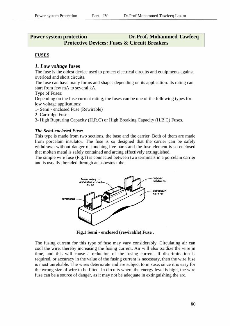
The Semi-enclosed Fuse:
This type is made from two sections, the base and the carrier. Both of them are made
from porcelain insulator. The fuse is so designed that the carrier can be safely
withdrawn without danger of touching live parts and the fuse element is so enclosed
that molten metal is safely contained and arcing effectively extinguished. The simple wire fuse (Fig.1) is connected between two terminals in a porcelain carrier
and is usually threaded through an asbestos tube.
Fig.1 Semi - enclosed (rewirable) Fuse .
The fusing current for this type of fuse may vary considerably. Circulating air can
cool the wire, thereby increasing the fusing current. Air will also oxidize the wire in
time, and this will cause a reduction of the fusing current. If discrimination is
required, or accuracy in the value of the fusing current is necessary, then the wire fuse
is most unreliable. The wires deteriorate and are subject to misuse, since it is easy for
the wrong size of wire to be fitted. In circuits where the energy level is high, the wire
fuse can be a source of danger, as it may not be adequate in extinguishing the arc.
Power system protection Dr.Prof. Mohammed Tawfeeq
Protective Devices: Fuses & Circuit Breakers
Power system Protection Part – IV Dr.Prof.Mohammed Tawfeeq Lazim
08
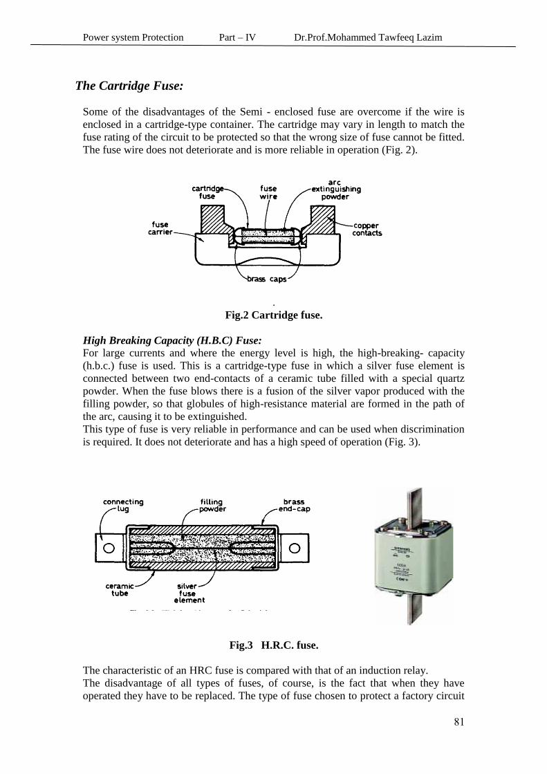
:The Cartridge Fuse
Some of the disadvantages of the Semi - enclosed fuse are overcome if the wire is
enclosed in a cartridge-type container. The cartridge may vary in length to match the
fuse rating of the circuit to be protected so that the wrong size of fuse cannot be fitted.
The fuse wire does not deteriorate and is more reliable in operation (Fig. 2).
.
Fig.2 Cartridge fuse.
High Breaking Capacity (H.B.C) Fuse:
For large currents and where the energy level is high, the high-breaking- capacity
(h.b.c.) fuse is used. This is a cartridge-type fuse in which a silver fuse element is
connected between two end-contacts of a ceramic tube filled with a special quartz
powder. When the fuse blows there is a fusion of the silver vapor produced with the
filling powder, so that globules of high-resistance material are formed in the path of
the arc, causing it to be extinguished.
This type of fuse is very reliable in performance and can be used when discrimination
is required. It does not deteriorate and has a high speed of operation (Fig. 3).
Fig.3 H.R.C. fuse.
The characteristic of an HRC fuse is compared with that of an induction relay.
The disadvantage of all types of fuses, of course, is the fact that when they have
operated they have to be replaced. The type of fuse chosen to protect a factory circuit
Power system Protection Part – IV Dr.Prof.Mohammed Tawfeeq Lazim
08
will depend upon the type of load and the circuit conditions. It is important to realize
the difference between the current rating of a fuse and its fusing current.
The current rating of a fuse is the current the fuse will carry continuously without
blowing or deteriorating.
The rated minimum fusing current is the minimum current at which the fuse will blow
in a specified time. This may vary between 1.25 and 2.5 times the current rating.
The relationship between the rated minimum fusing current and the current rating is
called the fusing factor:
.
Fusing factor = rated minimum fusing current / current rating
Classification of LV fuses
In British standard, there are four classes of fuses, depending upon their fusing
factors. These are as follows:
These having a fusing factor of 1.25 or less and provide protection Class P fuses
for circuits that cannot withstand even small sustained overloads. .
overcurrents but These fuses are for circuits that can withstand small Class Q fuses
give protection against higher values of overload. There are two types:
Class Q1—fusing factor between 1.25 and 1.5
Class Q2—fusing factor between 1.5 and 1.75
These fuses have a fusing factor between 1.75 and 2.5 and will Class R fuses
protect a circuit against relatively large over- currents only. Their main use is as back-
up protection where the normal protection is provided by some other device such as a
circuit breaker or a motor overload trip
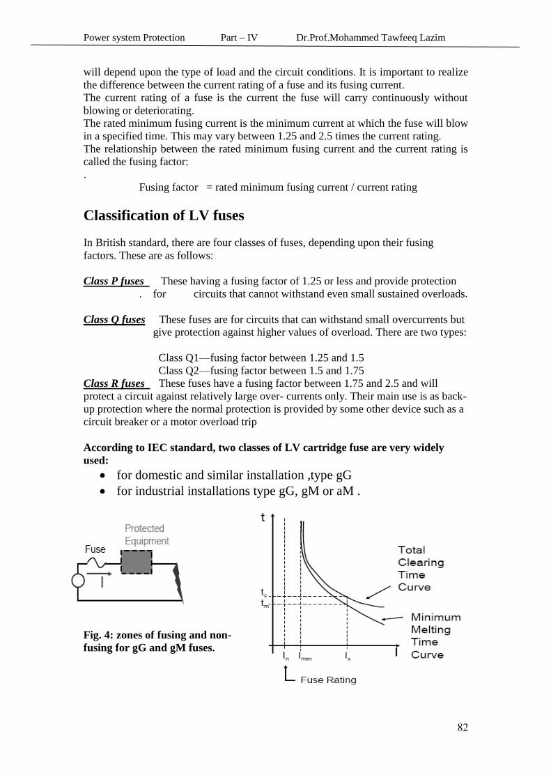
According to IEC standard, two classes of LV cartridge fuse are very widely
used:
for domestic and similar installation ,type gG
for industrial installations type gG, gM or aM .
Fig. 4: zones of fusing and non-
fusing for gG and gM fuses.
Power system Protection Part – IV Dr.Prof.Mohammed Tawfeeq Lazim
08
Class gG for protection of lighting circuit .While gM and aM for motor protection.
class aM fuses protect agains short-circuit currents only, and must t always be
associated with another device which protects against overload
As we did with melting time, we can draw a curve to represent the total clearing
time as a function of the current.
Following are the main characteristics of a fuse:
• The minimum melting time curve
• The total clearing time curve
• The fuse minimum melting current
• The fuse rating (nominal current) which should not be confused with the minimum
melting current.
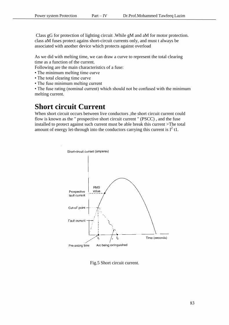
Short circuit Current When short circuit occurs between live conductors ,the short circuit current could
flow is known as the " prospective short circuit current " (PSCC) , and the fuse
installed to protect against such current must be able break this current >The total
amount of energy let-through into the conductors carrying this current is I2 t1.
Fig.5 Short circuit current.
Power system Protection Part – IV Dr.Prof.Mohammed Tawfeeq Lazim
08
The I 2 t factor of the fuse :
The time of operation of the fuse at high levels of current is inversely proportional to
the square of the current during the pre-arcing stage and proportional to the voltage
during the arcing stage.
For any conductor, its temperature rise depends on the I2t factor. This factor can be
calculated by empirical formula as:
For copper conductors
For Aluminum conductors
I = Short circuit current (A)
t = Duration of the short circuit (s)
A = Net cross – sectional area of the conductor (mm2)
θo = Initial temperature of the conductor (C⁰ )
θm =Final temperature of the conductor
If the pre-arcing I2t is not exceeded then there will be no deterioration of the fuse
performance. This is taken into account when discrimination is required between
fuses. If the total I2t of the smaller fuse is less than the pre-arcing I
2t of the larger fuse
then the smaller fuse would operate without causing any deterioration of the larger
fuse.
Example : It is proposed to use a No.30 AWG copper wire as a fuse element. If its
initial temperature is 50 C⁰, calculate the following:
(a) Tha I2t needed to melt the wire (copper melt at1083 C⁰ ).
(b) The time needed to melt the wire if the short circuit curreny is 30A. Solution From tables of wires 30 AWG = 0.0507 mm2
(a)
= 184 A2 s
(b) For a current of 30 A we obtain:
I2t = 184
(30)2 t = 184
t = 0.2 sec.
Power system Protection Part – IV Dr.Prof.Mohammed Tawfeeq Lazim
08
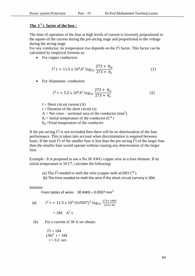
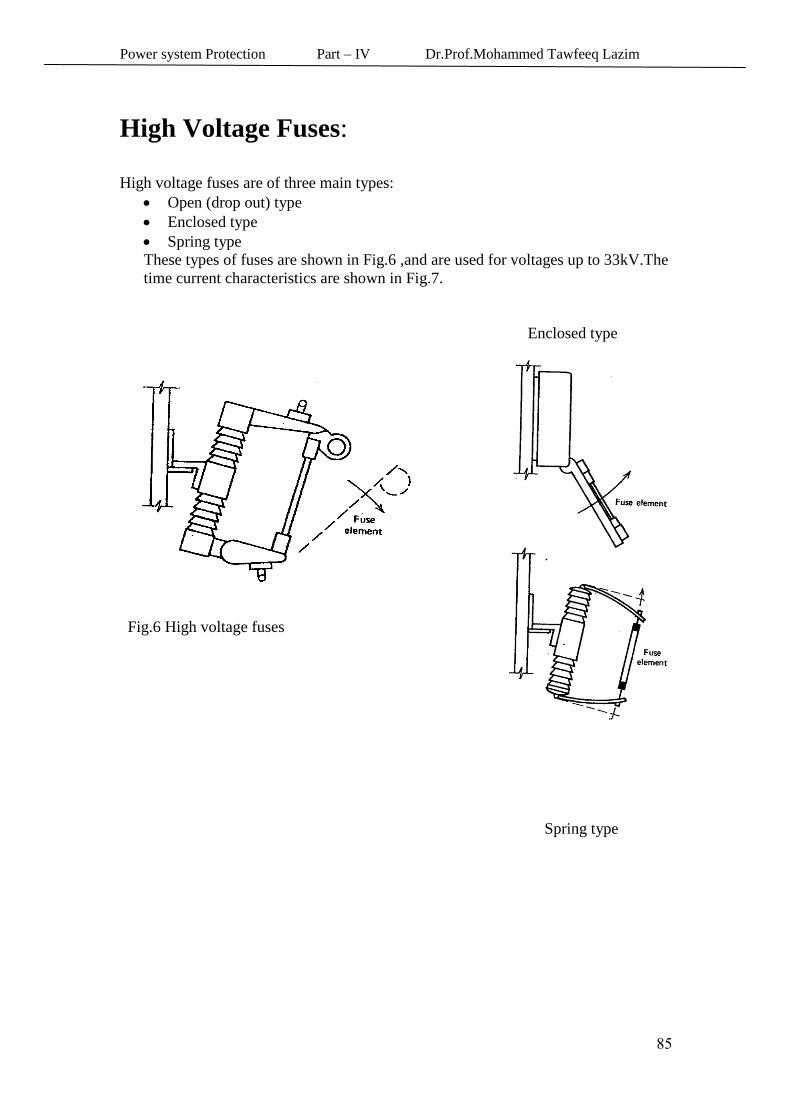
High Voltage Fuses:
High voltage fuses are of three main types:
Open (drop out) type
Enclosed type
Spring type
These types of fuses are shown in Fig.6 ,and are used for voltages up to 33kV.The
time current characteristics are shown in Fig.7.
Enclosed type
Drop out type fuse
Fig.6 High voltage fuses
Spring type
Power system Protection Part – IV Dr.Prof.Mohammed Tawfeeq Lazim
08
Power system protection Dr.Prof.. Mohammed Tawfeeq
Protective Devices: Fuses & Circuit Breakers
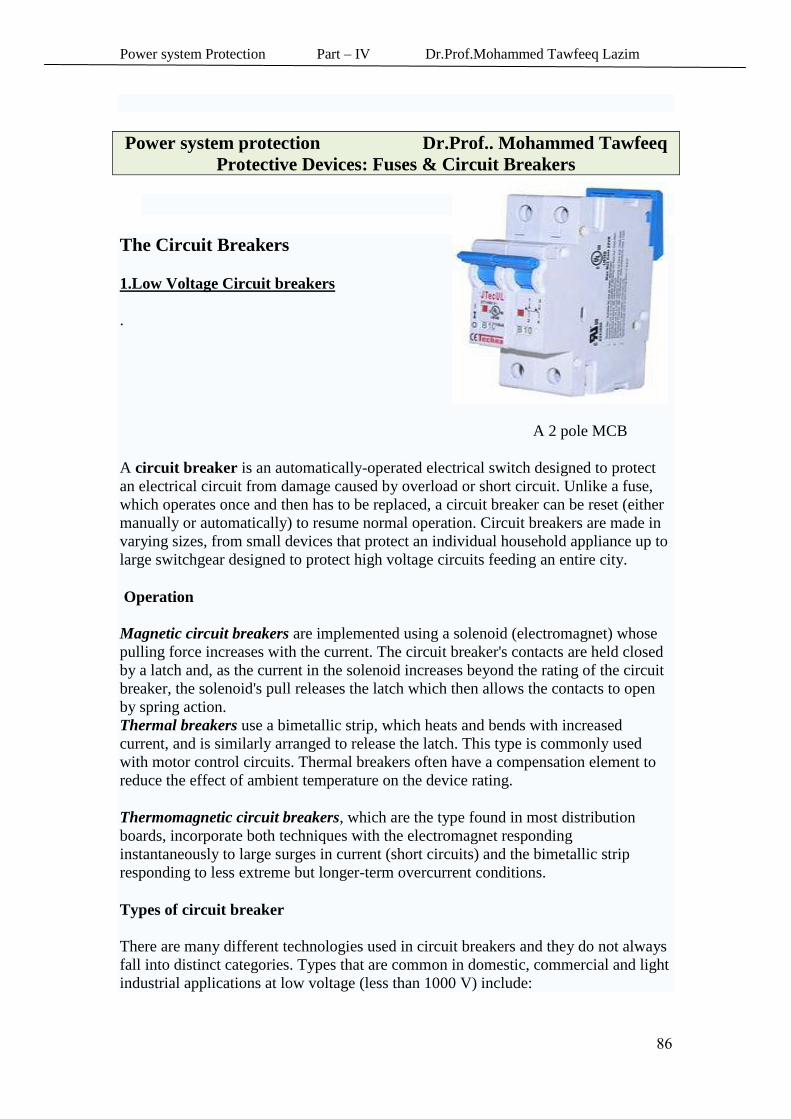
The Circuit Breakers
1.Low Voltage Circuit breakers
.
A 2 pole MCB
A circuit breaker is an automatically-operated electrical switch designed to protect
an electrical circuit from damage caused by overload or short circuit. Unlike a fuse,
which operates once and then has to be replaced, a circuit breaker can be reset (either
manually or automatically) to resume normal operation. Circuit breakers are made in
varying sizes, from small devices that protect an individual household appliance up to
large switchgear designed to protect high voltage circuits feeding an entire city.
Operation
Magnetic circuit breakers are implemented using a solenoid (electromagnet) whose
pulling force increases with the current. The circuit breaker's contacts are held closed
by a latch and, as the current in the solenoid increases beyond the rating of the circuit
breaker, the solenoid's pull releases the latch which then allows the contacts to open
by spring action.
Thermal breakers use a bimetallic strip, which heats and bends with increased
current, and is similarly arranged to release the latch. This type is commonly used
with motor control circuits. Thermal breakers often have a compensation element to
reduce the effect of ambient temperature on the device rating.
Thermomagnetic circuit breakers, which are the type found in most distribution
boards, incorporate both techniques with the electromagnet responding
instantaneously to large surges in current (short circuits) and the bimetallic strip
responding to less extreme but longer-term overcurrent conditions.
Types of circuit breaker
There are many different technologies used in circuit breakers and they do not always
fall into distinct categories. Types that are common in domestic, commercial and light
industrial applications at low voltage (less than 1000 V) include:
Power system Protection Part – IV Dr.Prof.Mohammed Tawfeeq Lazim
09
MCB (Miniature Circuit Breaker)—rated current not more than 100 A. Trip
characteristics normally not adjustable. Thermal or thermal-magnetic
operation. Breakers illustrated above are in this category.
MCCB (Moulded Case Circuit Breaker)—rated current up to 1000 A.
Thermal or thermal-magnetic operation. Trip current may be adjustable.
ACB (Air circuit breaker) – rated current up to 4000 A .Thermal and
magnetic operation . Trip current adjustaible.
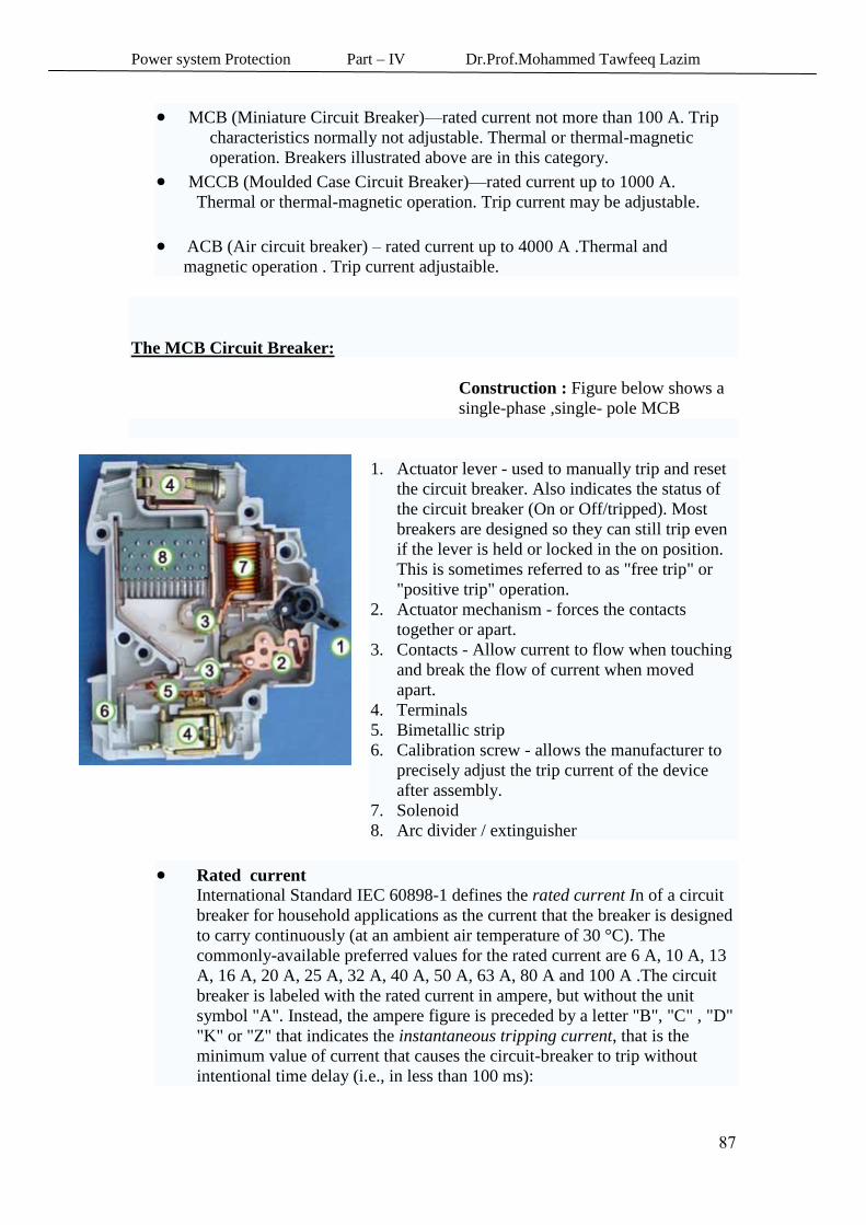
The MCB Circuit Breaker:
Construction : Figure below shows a
single-phase ,single- pole MCB
1. Actuator lever - used to manually trip and reset
the circuit breaker. Also indicates the status of
the circuit breaker (On or Off/tripped). Most
breakers are designed so they can still trip even
if the lever is held or locked in the on position.
This is sometimes referred to as "free trip" or
"positive trip" operation.
2. Actuator mechanism - forces the contacts
together or apart.
3. Contacts - Allow current to flow when touching
and break the flow of current when moved
apart.
4. Terminals
5. Bimetallic strip
6. Calibration screw - allows the manufacturer to
precisely adjust the trip current of the device
after assembly.
7. Solenoid
8. Arc divider / extinguisher
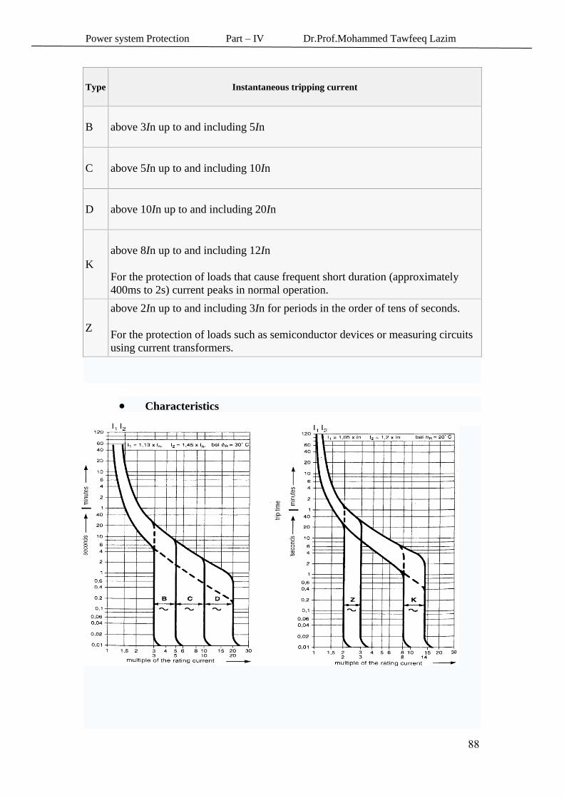
Rated current International Standard IEC 60898-1 defines the rated current In of a circuit
breaker for household applications as the current that the breaker is designed
to carry continuously (at an ambient air temperature of 30 °C). The
commonly-available preferred values for the rated current are 6 A, 10 A, 13
A, 16 A, 20 A, 25 A, 32 A, 40 A, 50 A, 63 A, 80 A and 100 A .The circuit
breaker is labeled with the rated current in ampere, but without the unit
symbol "A". Instead, the ampere figure is preceded by a letter "B", "C" , "D"
"K" or "Z" that indicates the instantaneous tripping current, that is the
minimum value of current that causes the circuit-breaker to trip without
intentional time delay (i.e., in less than 100 ms):
Power system Protection Part – IV Dr.Prof.Mohammed Tawfeeq Lazim
00
Type Instantaneous tripping current
B above 3In up to and including 5In
C above 5In up to and including 10In
D above 10In up to and including 20In
K
above 8In up to and including 12In
For the protection of loads that cause frequent short duration (approximately
400ms to 2s) current peaks in normal operation.
Z
above 2In up to and including 3In for periods in the order of tens of seconds.
For the protection of loads such as semiconductor devices or measuring circuits
using current transformers.
Characteristics
Power system Protection Part – IV Dr.Prof.Mohammed Tawfeeq Lazim
07
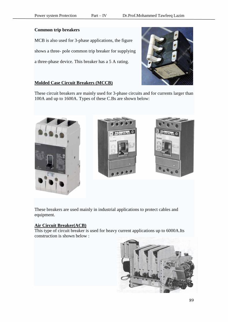
Common trip breakers
MCB is also used for 3-phase applications, the figure
shows a three- pole common trip breaker for supplying
a three-phase device. This breaker has a 5 A rating.
Molded Case Circuit Breakers (MCCB)
These circuit breakers are mainly used for 3-phase circuits and for currents larger than
100A and up to 1600A. Types of these C.Bs are shown below:
These breakers are used mainly in industrial applications to protect cables and
equipment.
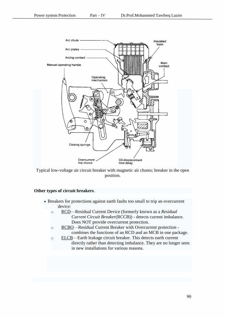
Air Circuit Breaker(ACB)
This type of circuit breaker is used for heavy current applications up to 6000A.Its
construction is shown below :
Power system Protection Part – IV Dr.Prof.Mohammed Tawfeeq Lazim
78
Typical low-voltage air circuit breaker with magnetic air chutes; breaker in the open
position.
Other types of circuit breakers.
Breakers for protections against earth faults too small to trip an overcurrent
device:
o RCD—Residual Current Device (formerly known as a Residual
Current Circuit Breaker(RCCB)) - detects current imbalance.
Does NOT provide overcurrent protection.
o RCBO—Residual Current Breaker with Overcurrent protection -
combines the functions of an RCD and an MCB in one package.
o ELCB—Earth leakage circuit breaker. This detects earth current
directly rather than detecting imbalance. They are no longer seen
in new installations for various reasons.
Power system Protection Part – IV Dr.Prof.Mohammed Tawfeeq Lazim
78
Power system protection Dr. Prof.Mohammed Tawfeeq
Protective Devices: Fuses & Circuit Breakers
High Voltage Circuit breakers
The most important types of H.V circuit breakers are the following:
( .Oil circuit breakers (OCBs 1-
. 2- SF6 circuit breakers
.3-Vacuum circuit break
4- Air-blast circuit breaker
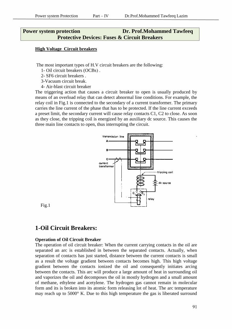
The triggering action that causes a circuit breaker to open is usually produced by
means of an overload relay that can detect abnormal line conditions. For example, the
relay coil in Fig.1 is connected to the secondary of a current transformer. The primary
carries the line current of the phase that has to be protected. If the line current exceeds
a preset limit, the secondary current will cause relay contacts C1, C2 to close. As soon
as they close, the tripping coil is energized by an auxiliary dc source. This causes the
three main line contacts to open, thus interrupting the circuit.
.
Fig.1
1-Oil Circuit Breakers:
Operation of Oil Circuit Breaker
The operation of oil circuit breaker: When the current carrying contacts in the oil are
separated an arc is established in between the separated contacts. Actually, when
separation of contacts has just started, distance between the current contacts is small
as a result the voltage gradient between contacts becomes high. This high voltage
gradient between the contacts ionized the oil and consequently initiates arcing
between the contacts. This arc will produce a large amount of heat in surrounding oil
and vaporizes the oil and decomposes the oil in mostly hydrogen and a small amount
of methane, ethylene and acetylene. The hydrogen gas cannot remain in molecular
form and its is broken into its atomic form releasing lot of heat. The arc temperature
may reach up to 5000° K. Due to this high temperature the gas is liberated surround
Power system Protection Part – IV Dr.Prof.Mohammed Tawfeeq Lazim
78
the arc very rapidly and forms an excessively fast growing gas bubble around the arc.
It is found that the mixture of gases occupies a volume about one thousand times that
of the oil decomposed. From this figure we can assume how fast the gas bubble
around the arc will grow in size. If this growing gas bubble around the arc is
compressed by any means then rate of de – ionization process of ionized gaseous
media in between the contacts will accelerate which rapidly increase the dielectric
strength between the contacts and consequently the arc will be quenched at zero
crossing of the current cycle. This is the basic operation of oil circuit breaker. In
addition to that cooling effect of hydrogen gas surround the arc path also helps, the
quick arc quenching in oil circuit breaker.
Types of Oil Circuit Breakers
There are mainly two types of oil circuit breakers available-
Bulk Oil Circuit Breaker or BOCB
Minimum Oil Circuit Breaker or MOCB
Bulk oil circuit breakers
Bulk oil circuit breaker or BOCB is such types of circuit breakers where oil is
used as arc quenching media as well as insulating media between current
carrying contacts and earthed parts of the breaker. The oil used here is same
as transformer insulating oil.
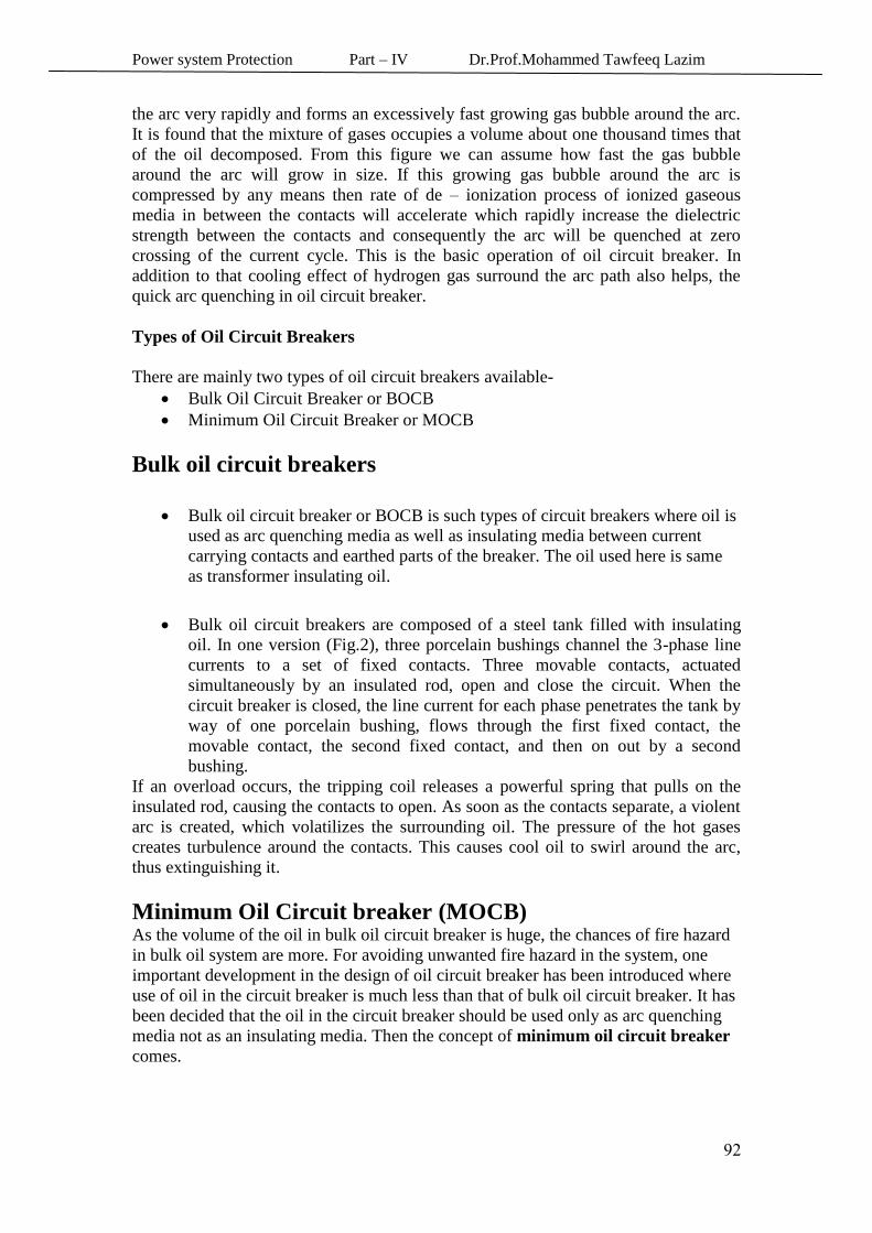
Bulk oil circuit breakers are composed of a steel tank filled with insulating
oil. In one version (Fig.2), three porcelain bushings channel the 3-phase line
currents to a set of fixed contacts. Three movable contacts, actuated
simultaneously by an insulated rod, open and close the circuit. When the
circuit breaker is closed, the line current for each phase penetrates the tank by
way of one porcelain bushing, flows through the first fixed contact, the
movable contact, the second fixed contact, and then on out by a second
bushing.
If an overload occurs, the tripping coil releases a powerful spring that pulls on the
insulated rod, causing the contacts to open. As soon as the contacts separate, a violent
arc is created, which volatilizes the surrounding oil. The pressure of the hot gases
creates turbulence around the contacts. This causes cool oil to swirl around the arc,
thus extinguishing it.
Minimum Oil Circuit breaker (MOCB) As the volume of the oil in bulk oil circuit breaker is huge, the chances of fire hazard
in bulk oil system are more. For avoiding unwanted fire hazard in the system, one
important development in the design of oil circuit breaker has been introduced where
use of oil in the circuit breaker is much less than that of bulk oil circuit breaker. It has
been decided that the oil in the circuit breaker should be used only as arc quenching
media not as an insulating media. Then the concept of minimum oil circuit breaker
comes.
Power system Protection Part – IV Dr.Prof.Mohammed Tawfeeq Lazim
78
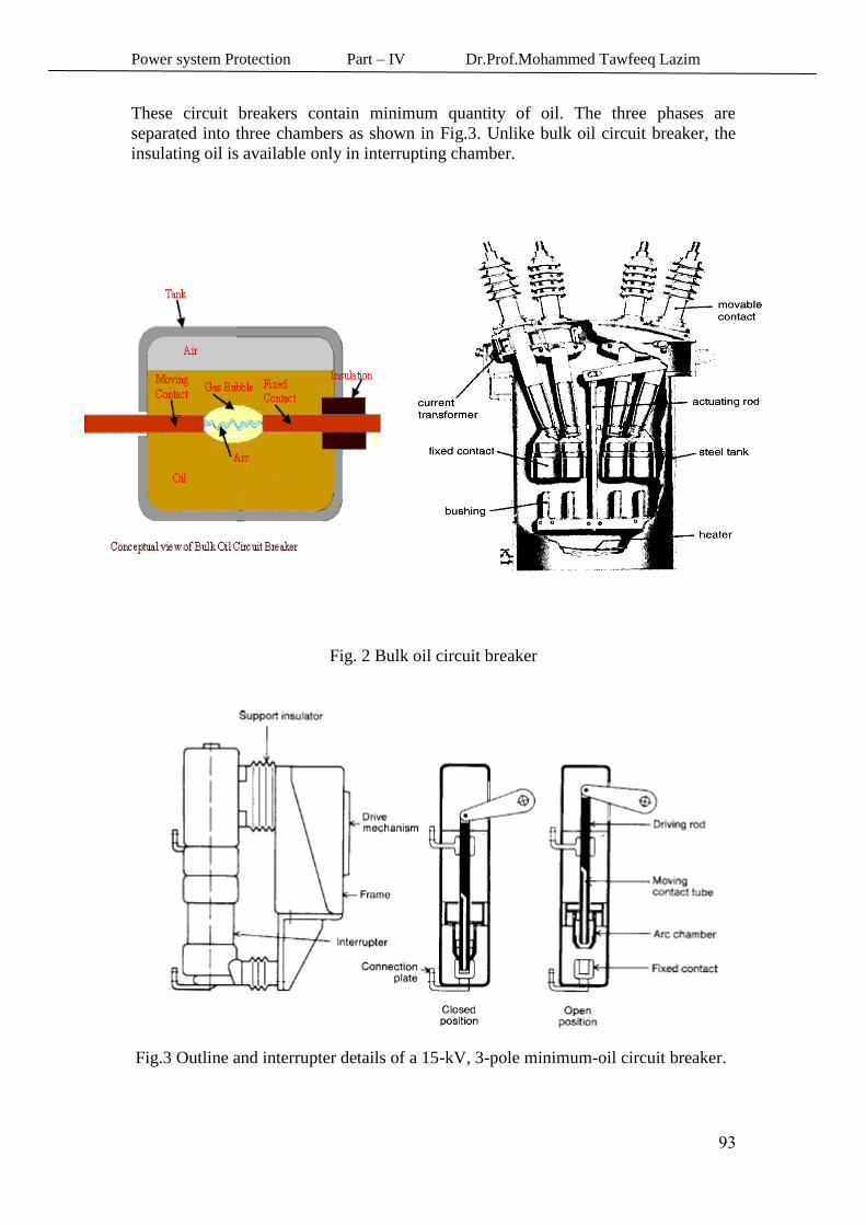
These circuit breakers contain minimum quantity of oil. The three phases are
separated into three chambers as shown in Fig.3. Unlike bulk oil circuit breaker, the
insulating oil is available only in interrupting chamber.
Fig. 2 Bulk oil circuit breaker
Fig.3 Outline and interrupter details of a 15-kV, 3-pole minimum-oil circuit breaker.
Power system Protection Part – IV Dr.Prof.Mohammed Tawfeeq Lazim
78
2 - SF6 Circuit Breakers
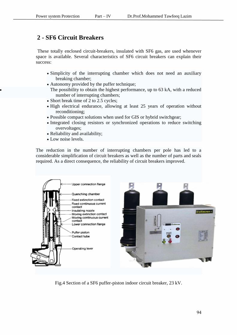
These totally enclosed circuit-breakers, insulated with SF6 gas, are used whenever
space is available. Several characteristics of SF6 circuit breakers can explain their
success:
Simplicity of the interrupting chamber which does not need an auxiliary
breaking chamber;
Autonomy provided by the puffer technique;
The possibility to obtain the highest performance, up to 63 kA, with a reduced
number of interrupting chambers;
Short break time of 2 to 2.5 cycles;
High electrical endurance, allowing at least 25 years of operation without
reconditioning;
Possible compact solutions when used for GIS or hybrid switchgear;
Integrated closing resistors or synchronized operations to reduce switching
overvoltages;
Reliability and availability;
Low noise levels.
The reduction in the number of interrupting chambers per pole has led to a
considerable simplification of circuit breakers as well as the number of parts and seals
required. As a direct consequence, the reliability of circuit breakers improved.
Fig.4 Section of a SF6 puffer-piston indoor circuit breaker, 23 kV.
Power system Protection Part – IV Dr.Prof.Mohammed Tawfeeq Lazim
78
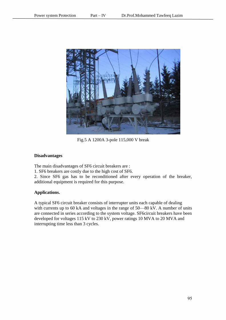
Fig.5 A 1200A 3-pole 115,000 V break
Disadvantages
The main disadvantages of SF6 circuit breakers are :
1. SF6 breakers are costly due to the high cost of SF6.
2. Since SF6 gas has to be reconditioned after every operation of the breaker,
additional equipment is required for this purpose.
Applications.
A typical SF6 circuit breaker consists of interrupter units each capable of dealing
with currents up to 60 kA and voltages in the range of 50—80 kV. A number of units
are connected in series according to the system voltage. SF6circuit breakers have been
developed for voltages 115 kV to 230 kV, power ratings 10 MVA to 20 MVA and
interrupting time less than 3 cycles.
Power system Protection Part – IV Dr.Prof.Mohammed Tawfeeq Lazim
78
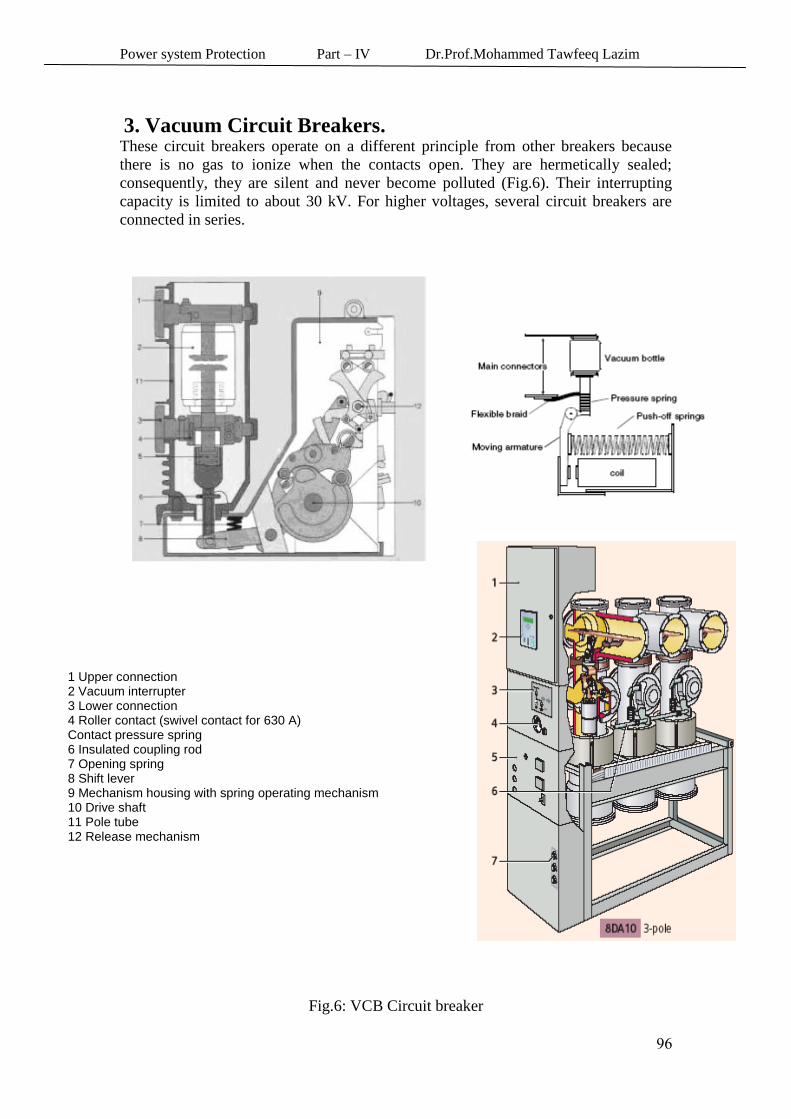
3. Vacuum Circuit Breakers.
These circuit breakers operate on a different principle from other breakers because
there is no gas to ionize when the contacts open. They are hermetically sealed;
consequently, they are silent and never become polluted (Fig.6). Their interrupting
capacity is limited to about 30 kV. For higher voltages, several circuit breakers are
connected in series.
1 Upper connection 2 Vacuum interrupter 3 Lower connection 4 Roller contact (swivel contact for 630 A) 5 Contact pressure spring 6 Insulated coupling rod 7 Opening spring 8 Shift lever 9 Mechanism housing with spring operating mechanism 10 Drive shaft 11 Pole tube 12 Release mechanism
Fig.6: VCB Circuit breaker
Power system Protection Part – IV Dr.Prof.Mohammed Tawfeeq Lazim
79
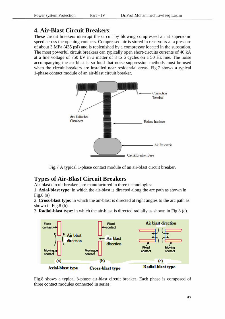
4. Air-Blast Circuit Breakers:
These circuit breakers interrupt the circuit by blowing compressed air at supersonic
speed across the opening contacts. Compressed air is stored in reservoirs at a pressure
of about 3 MPa (435 psi) and is replenished by a compressor located in the substation.
The most powerful circuit breakers can typically open short-circuits currents of 40 kA
at a line voltage of 750 kV in a matter of 3 to 6 cycles on a 50 Hz line. The noise
accompanying the air blast is so loud that noise-suppression methods must be used
when the circuit breakers are installed near residential areas. Fig.7 shows a typical
1-phase contact module of an air-blast circuit breaker.
Fig.7 A typical 1-phase contact module of an air-blast circuit breaker.
Types of Air-Blast Circuit Breakers Air-blast circuit breakers are manufactured in three technologies:
1. Axial-blast type: in which the air-blast is directed along the arc path as shown in
Fig.8 (a)
2. Cross-blast type: in which the air-blast is directed at right angles to the arc path as
shown in Fig.8 (b).
3. Radial-blast type: in which the air-blast is directed radially as shown in Fig.8 (c).
Fig.8 shows a typical 3-phase air-blast circuit breaker. Each phase is composed of
three contact modules connected in series.
Power system Protection Part – IV Dr.Prof.Mohammed Tawfeeq Lazim
70
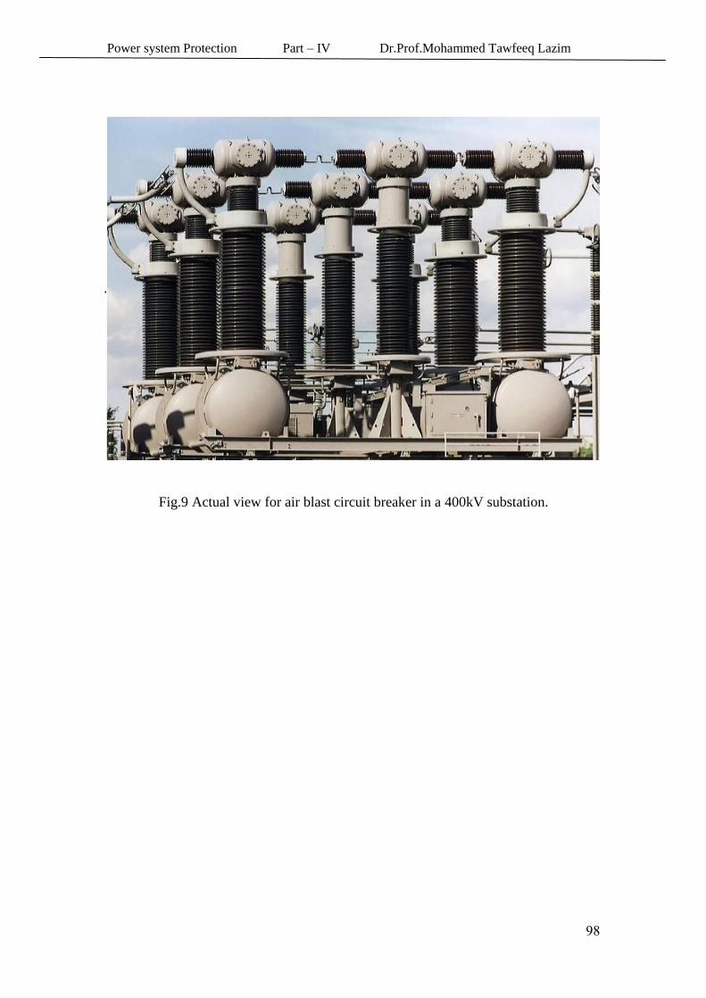
Fig.9 Actual view for air blast circuit breaker in a 400kV substation.