Proposed Expansion Project For Manufacturing of Synthetic...
55
PROJECT PRE-FEASIBILITY REPORT For Proposed Expansion Project For Manufacturing of Synthetic Organic Chemicals AT Plot No. 119, II nd Phase GIDC Vapi, Dist. Valsad. Project Proponent M/s. Ideal Dye Chem Industries (Unit-I)
Transcript of Proposed Expansion Project For Manufacturing of Synthetic...

PROJECT PRE-FEASIBILITY REPORT
For
Proposed Expansion Project
For
Manufacturing of
Synthetic Organic Chemicals
AT
Plot No. 119, IInd Phase GIDC Vapi,
Dist. Valsad.
Project Proponent
M/s. Ideal Dye Chem Industries (Unit-I)

i
CONTENTS
Chapters
S. No. Particulars Page No.
1 Executive Summary 1-32 Introduction Of The Project 4-5
2.1 Identification of the Project And Project Proponent 42.1.1 Identification of the Project 42.1.2 Details of Project Proponent 42.1.3 Nature of the Project 42.1.4 Need of Project & Demand-Supply Gap 42.1.5 Domestic / Export Market 42.1.6 Employment Generation due to Project 53 Project Discription 6-213.1 Identification of the Project and Project Proponent 63.1.1 Identification of the Project 63.1.2 Location 63.2 Details of Alternative Site 103.3 Size & Magnitude Of Operation 103.4 Project Discription With Process Details 103.5 Raw Material For Finished Product 103.6 Material Storage & Transportation 113.7 Resource Optimization& Availability 123.7.1 Land & Building 123.7.2 Equipment and Machinery 123.7.3 Power Requirement 133.7.4 Fuel Requirement 133.7.5 Man-Power 133.7.6 Fresh water Requirement 133.8 Quantity Of Waste to be Generated 143.8.1 Wastewater Generation & Management 143.8.2 Wastewater Characteristics 173.8.3 Wastewater Treatment & Disposal 173.8.4 Air Emissions & Control 183.8.4.1 Process Emission 183.8.4.2 Utility Emission 183.8.4.3 Fugitive Emission 183.8.5 Hazardous/Non-Hazardous Wastes Management 193.8.6 Noise Control 193.9 Health And Safety Measures 193.10 Environmental Health & Safety Cell 203.11 Post Project Monitoring Plan 214 Site Analysis 22-244.1 Connectivity 224.2 Land Form, Land Use & Land Ownership 224.3 Topography 224.4 Salient Features 224.5 Existing Infrastructure 224.6 Soil Classification 224.7 Climate & Meterology 234.7.1 Temperature 234.7.2 Humidity 23

ii
S. No. Particulars Page No.4.7.3 Rainfall 234.7.5 Wind Pattern 244.7.6 Social Infrastructure 244.7.7 Educational Facilities 244.7.8 Medical Facilities 245 Planning Brief 25-255.1 Planning Concept 255.2 Population Projection 255.3 Area Statement 255.4 Assesment Of Infrastructure Demand (Physical & Social) 255.5 Amenities/Facilities 255.5.1 Drinking Water Facilities 255.5.2 Power Supply Facilities 255.5.3 Communication & Banking Facilities 255.5.4 Transport Facilities 256 Proposed Infrastructure 26-266.1 Industrial Area 266.2 Residential Area 266.3 Greenbelt 266.4 Social Infrastructure 266.5 Connectivity 266.6 Drinking Water Management 266.7 Sewerage System 266.8 Industrial Waste Management 266.9 Solid Waste Management 266.10 Power Requirement & Source Of Supply 267 Rehabilitation & Resettlement ( R& R) Plan 27-277.1 Policy To Be Adopted 278 Project Schedule & Cost Estimates 28-288.1 Time Schedule Of The Project 288.2 Estimated Project Cost 289 Analysis Of Proposal 29-299.1 Financial & Social Benefits 29

iii
List of Tables Table No. Topic Page No.1.1 Project Summary 12.1 List of Proposed Products 42.2 List of Partners 43.1 Area Statement 103.2 List of Raw Material 103.3 Hazardous chemicals, its storage and handling 113.4 List of Equipment and machinery 123.5 Man-Power Requirement 133.6 Total Water Consumption 133.7 Category-wise Wastewater Generation 143.8 Composite Characteristics of Wastewater to ETP 173.9 ETP Unit Details 173.10 Details of process emissions 183.11 Details of utility emissions 183.12 Hazardous and Non-hazardous waste generation, management and
Disposal 19
3.13 Environmental Monitoring Plan 214.1 Salient Features of the Project Site 224.2 Summary Meteorological Data At Nearest Imd Station- Dahanu 235.1 Distribution of Population 258.1 Total Capital Cost Projection 28
List of Figures Sr. No. Description Page No.3.1 Project Site 73.2 Satellite Image of The Project Site 83.3 Plant Layout 93.4 Water Balance Diagram - Existing Scenario (in kl/day) 153.5 Water Balance Diagram - Proposed Scenario (in kl/day) 163.6 Process Flow Diagram of Existing Effluent Treatment Plant 173.7 Organogram of EHS Cell 20
List of Annexures
Sr. No. Description Annexure 1 Existing CC&A Annexure 2 Process TechnologyAnnexure 3 Land Document Annexure-4 Membership certificate of CETP & TSDF

Project Prefeasibility Report
Project: Project for manufacturing of Synthetic Organic Chemical 1 | P a g e
CHAPTER – 1
EXECUTIVE SUMMARY
The project is summarized in the below table:
Table1.1: Project Summary
PARTICULARS DETAILS Name of the unit M/s. Ideal Dye Chem Industries (Unit-I)Occupier Mr. Premji S. Hemani and Mr. Mohan S. DamaProducts The list of products is as below:
Sr. No.
Name of Products Quantity T/month
Existing Proposed
Additional Total
1 Ortho Dianisidine Dihydrochloride 7.0 50.0 57.02 4B Acid 5.0 - 5.03 2B Acid 2.0 - 2.04 Tetra Chloro Benzidine-2HCl - 10.0 10.05 3,3 Dichlorobenzidine-2HCl - 100.0 100.06 Ortho Toludine-2HCl - 10.0 10.0
TOTAL 14.0 170.0 184.0Note: The company has obtained CC&A for its existing products vide consent order AWH-50042 dated 12/08/2017
Location Plot No. 119, IInd Phase, G.I.D.C Vapi, Dist: Valsad. Nature of project
Proposed expansion project for manufacturing of Synthetic Organic Chemical.
RESOURCES Resource type Requirement SourceLand Existing Operations: 2090 m2
Proposed additional: NILGIDC Vapi
Water Existing Operations: Domestic: 7 kl/day Industrial: 34 kl/day Gardening: 2 kl/day Total: 43 kl/day After Proposed Expansion Project: Domestic: 12 kl/day Industrial: 219 kl/day Gardening: 6 kl/day Total: 237 kl/day
The freshwater is/will be sourced from GIDC water supply department.
Power Existing Operations: 250 kVA Proposed additional: 500 kVA
Dakshin Gujarat Vij Co. Ltd. (DGVCL)
Fuel Existing Operations: Natural gas: 1347 SCM/day Diesel: 40 liter/hr Proposed additional: Natural gas: 2694 SCM/day
Natural gas is/will be sourced from Gujarat Gas limited. Diesel is/will be sourced from local supplier
POLLUTION POTENTIAL & MITIGATION MEASURESParameter Potential Mitigation Wastewater Existing Operations:
Domestic: 5 kl/day Industrial: 22 kl/day Total: 27 kl/day After Proposed Expansion Project: Domestic: 8 kl/day Industrial: 92 kl/day Total: 100 kl/day
The domestic wastewater is/will be disposed through septic tank/ soak pit system. In existing operations, total @22 kl/day industrial wastewater is generated. The wastewater from process is bifurcated as high concentrated stream

Project Prefeasibility Report
Project: Project for manufacturing of Synthetic Organic Chemical 2 | P a g e
PARTICULARS DETAILS @1.5 kl/day and low concentrated stream @20.5 kl/day. The high concentrated stream is sent to common MEE and low concentrated stream is mixed with other industrial effluent and treated in ETP. The treated effluent from ETP is disposed to CETP through underground drainage pipelines. After the proposed expansion project, same process will be followed, and necessary modifications will be done in existing ETP to cater the additional load.
Air Emissions Process emissions: Existing and Proposed operations: HCl gas during manufacturing of 2B acid. Utility emissions: Existing Operations: Steam Boiler- 2.0 TPH (1 No) Thermic fluid heater D.G. set – 125 kVA (Stand-by). Proposed additional: Steam Boiler – 2.0 TPH (1 No) Fugitive emissions: Fugitive emissions is/will be in form of storage and handling of chemicals.
Process gas emission is/will be in form of HCl gas. The company has already installed caustic scrubber for scrubbing. The wastewater generated from scrubber is/will be sent to ETP for further treatment. Adequate stack height is already provided to process stack. Adequate stack height is/will be provided to all the utility stacks. Natural gas is/will be used as fuel in boiler and thermic fluid heater. Diesel is/will be used as fuel in D.G. set. Designated storage area is/will be provided for storage of chemicals/ raw materials. Good housekeeping is/will be maintained in the plant. It is/will be reduced in terms of storage and handling.
Hazardous & solid waste
Existing Scenario: ETP Waste (Cat-26.2)- 180
T/annum Iron Sludge (Cat-26.1)- 48 T/annum Sludge from wet scrubber (Cat-
36.1)- 0.12 T/annum Used oil (Cat-5.1)- 100 Lit/annum. Discarded Containers/Bags (Cat-
33.3)- 1200 Nos/annum Proposed Scenario: ETP Waste (Cat-26.2)- 684
T/annum Iron Sludge (Cat-26.1)- 48 T/annum Sludge from wet scrubber (Cat-
36.1)- 0.12 T/annum Used oil (Cat-5.1)- 100 liter/annum. Discarded Containers/Bags (Cat-
33.3)- 2500 Nos/annum
ETP waste, Iron sludge and sludge from wet scrubber is/will be collected, stored, transported and disposed at TSDF-VWEMCL. Used oil is/will be reused in plant as lubricant in machineries. Discarded containers/bags is/will be collected, stored and disposal by selling to registered reprocessors.

Project Prefeasibility Report
Project: Project for manufacturing of Synthetic Organic Chemical 3 | P a g e
PARTICULARS DETAILS Noise Plant premises
<75 dB(A) during day time <70 dB(A) during night time
D.G. set is/will be provided with acoustic enclosures. Ear plug/ ear muff is/will be provided to workers in the plant.
(Source: Ideal Dye Chem Industries (U-I))

Project Prefeasibility Report
Project: Project for manufacturing of Synthetic Organic Chemical 4 | P a g e
CHAPTER – 2
INTRODUCTION OF THE PROJECT
2.1 IDENTIFICATION OF THE PROJECT AND PROJECT PROPONENT
2.1.1 Identification of the Project
M/s. Ideal Dye Chem Industries (U-I). is an operational unit manufacturing “Synthetic Organic Chemical” at Plot No. 119, II Phase, G.I.D.C Vapi, Dist.: Valsad. The unit has obtained CC&A for its existing plant vide CC&A No.: AWH-50042 dated 08/10/2012 and valid up to 12/08/2017.
Now the company is planning for increase in existing production capacity by adding similar category product from 14 T/month to 184 T/month. The copy of existing CC&A is attached as Annexure -1. The list of products are as follows:
Table 2.1: List of Proposed Products
Sr. No.
Name of Products Quantity (T/month)Existing Proposed Additional Total
1 Ortho Dianisidine Dihydrochloride 7 50 572 4B Acid 5 - 53 2B Acid 2 - 24 Tetra Chloro Benzidine - 10 105 3,3 Dichlorobenzidine-2HCl - 100 1006 Ortho Toludine - 10 10
TOTAL 14 170 184Note: The company has obtained CC&A for its existing products vide consent order AWH-50042 dated 12/08/2017
(Source: Ideal Dye Chem Industries (U-I))
2.1.2 Details of Project Proponent
The list of the partners is given below:
Table 2.2: List of Partners
S. No. Name of Partners Designation Residential Address1. Shree Premji S. Hemani Partner B-18/73, New Type, GIDC, Vapi-396 195 Dist.
Valsad (Gujarat). Phone: (0260) 2431454.2. Shree Mohan. S. Dama Partner Room No. 91/2, Bhanushali Wadi, 4th Floor,
Ghatkopar (E) Mumbai- 400077 (Source: Ideal Dye Chem Industries (U-I))
2.1.3 Nature of the Project
The proposed expansion project involves the production of “Synthetic Organic Chemicals”, which falls under item no. 5(f) i.e. Synthetic Organic Chemical manufacturing and under the category B as per the EIA notification, 14 September 2006 (as amended from time to time).
2.1.4 Need of Project & Demand-Supply Gap
The proposed products have domestic as well as international demand which will in turn generate dollar revenue for the nation. Also proposed project will help to provide new jobs for nearby people.
2.1.5 Domestic / Export Markets
Market for the proposed products includes not only the domestic market but also the international market.

Project Prefeasibility Report
Project: Project for manufacturing of Synthetic Organic Chemical 5 | P a g e
2.1.6 Employment Generation due to Project
The proposed expansion project will provide direct employment opportunity to local persons. The man-power required for the proposed expansion project will be employed locally from the nearby areas.

Project Prefeasibility Report
Project: Project for manufacturing of Synthetic Organic Chemical 6 | P a g e
CHAPTER – 3
PROJECT DESCRIPTION
3.1 IDENTIFICATION OF THE PROJECT AND PROJECT PROPONENT
3.1.1 Identification of the Project
The proposed expansion project involves the manufacturing of synthetic organic chemicals at the existing site located in the notified industrial estate of GIDC Vapi.
3.1.2 Location
The area is situated in the southernmost part of the Gujarat, which is adjacent to coastal area in western side and hill area in eastern side. Interstate boundary of Daman and Gujarat is situated in western side at approximately 5.0 kms. The nearest city/ town to the project site is Vapi.
Vapi is a city and a municipality in Valsad district in the state of Gujarat. It is situated on the banks of Damanganga River in southern Gujarat. It falls under the taluka administration of Pardi. It is the largest city in the Valsad district.
Around 20 km south of the district headquarter city of Valsad, it is surrounded by Union Territories of Daman on the west and by Dadra and Nagar Haveli on the east. Economic and industrial growth of the recent decades has, however, blurred the physical boundaries, and the small stretch of roughly 21 km of Daman-Vapi-Silvassa has almost become a monolith.
Vapi is the largest industrial area in Asia in terms of small-scale industries, dominated by chemical industry plants. Mumbai is about 180 km to the south and Surat is about 125 km to the north. The “Vapi Industrial Estate” was started by GIDC in 1967, and has spread to 11.4 km² and houses over 1400 industries, the majority of which are small-scale units (SSIs).
The Arabian Sea is about 7 km to the west, where the Daman Ganga River creates its delta. The city has tropical weather and three distinct seasons of mild winter, moderate summer and heavy monsoon, with rainfall ranging from 100 inches to 120 inches per annum. Today, about 70% of the total industries in the township are chemical plants, mainly for chemical distillation and the production of pesticides, dyes, dye intermediaries and paints. Other major industries include paper, packaging, pharmaceuticals, plastics, rubber, textiles, wood, computer hardware & software, engineering workshop, glass, and food products. Another striking feature of Vapi is the Common Effluent Treatment Plant. This is the largest of its kind in Asia.
Vapi is surrounded by some magnificent location around it namely: Daman, Dadra, Silvassa, Umbergaon, Sarigam, Bhilad, Udavada, Sanjan, Pardi. Premises of Vapi are rich in all sorts, i.e. both the Union territories as well as Sarigam, Bhilad, Umbergaon & Pardi are good residential cum commercial areas, which are situated near Vapi within a mere distance of 20 km.
The location of the project site, satellite image and the layout are shown in figure 3.1 and 3.2 respectively.

Project Prefeasibility Report
Project: Project for manufacturing of Synthetic Organic Chemical 7 | P a g e
Figure 3.1: Project Site
(Source: Maps of India)
Project site

Project Prefeasibility Report
Project: Project for manufacturing of Synthetic Organic Chemical 8 | P a g e
Figure 3.2: Satellite Image of the Project Site
(Source: Google Earth)

Project Prefeasibility Report
Proposed expansion project for manufacturing of Synthetic Organic Chemical 9 | P a g e
Figure 3.3 Plant-Layout

Project Prefeasibility Report
Proposed expansion project for manufacturing of Synthetic Organic Chemical 10 | P a g e
(Source: Ideal Dye Chem Industries (U-I))
Table 3.1: Area Statement
Sr. No Particular Area (m2)1 Built-up area 789.932 Greenbelt area 500.003 Open area 800.07 Total Area 2090
(Source: Ideal Dye Chem Industries (U-I))
3.2 DETAILS OF ALTERNATIVE SITE
The existing site is located in the notified industrial estate of GIDC Vapi. Necessary infrastructure such as land, water etc. is easily available. Hence no alternative site is proposed.
3.3 SIZE & MAGNITUDE OF OPERATION
The total magnitude of operation will be @ 184 T/month after proposed expansion project.
3.4 PROJECT DESCRIPTION WITH PROCESS DETAILS
The process details like Process description, Material Balance and Chemical Reaction are given in Annexure 2.
3.5 RAW MATERIAL FOR FINISHED PRODUCT
The raw materials for the proposed range of products will be indigenously available and will be also imported. The product-wise raw-material consumption is given in table 3.2.
Table 3.2: List of raw materials
Sr. No.
Name of the product
Name of the raw material Quantitykg/batch kg/day kg/month
Existing products 1. Ortho Dianisidine
Dihydrochloride Ortho Nitro Anisole 1000 270.89 3250.68Caustic 910 246.51 2958.12Hydrogen Gas 55 14.9 178.8Toluene 2000 541.77 6501.24Sulphuric Acid (98% soln.) 1200 325.06 3900.72Sodium Chloride Salt 200 54.18 650.16
2. 4B Acid Ortho Dichloro Benzene 2500 265.63 3187.56Paranitro Toluene 1000 106.25 1275Sulphuric Acid 1000 106.25 1275Soda Ash 300 31.88 382.56Caustic soda flakes 200 21.25 255Hydrochloric acid (30-35% soln.) 1500 159.38 1912.56
3. 2B Acid Para Nitro Toluene 682 43.4 520.8Liquid Chlorine 350 22.28 267.36Iron 1350 85.91 1030.92Soda ash 125 7.96 95.52Caustic soda flakes 85 5.41 64.92Sulphuric Acid (98% soln.) 600 38.19 458.28Hydrochloric acid (30-35% soln.) 600 38.19 458.28
Proposed Products 4. Ortho Dianisidine
Dihydrochloride Ortho Nitro Anisole 1000 2144.47 25733.64Caustic 910 1951.47 23417.64Hydrogen Gas 55 117.95 1415.4Toluene 2000 4288.94 51467.28Sulphuric Acid (98% soln.) 1200 2573.37 30880.44Sodium Chloride Salt 200 428.9 5146.8

Project Prefeasibility Report
Proposed expansion project for manufacturing of Synthetic Organic Chemical 11 | P a g e
Sr. No.
Name of the product
Name of the raw material Quantitykg/batch kg/day kg/month
5. 4B Acid Ortho Dichloro Benzene 2500 265.63 3187.56Para Nitro Toluene 1000 106.25 1275Sulphuric Acid (98% soln.) 1000 106.25 1275Soda Ash 300 31.88 382.56Caustic soda flakes 200 21.25 255Hydrochloric acid (30-35% soln.) 1500 159.38 1912.56
6. 2B Acid Para Nitro Toluene 682 43.4 520.8Liquid chloride 350 22.28 267.36Iron 1350 85.91 1030.92Soda ash 125 7.96 95.52Caustic soda flakes 85 5.41 64.92Sulphuric Acid (98% soln.) 600 38.19 458.28Hydrochloric acid (30-35% soln.) 600 38.19 458.28
7. 3, 3 Dichlorobenzidine - 2HCl
Ortho Nitro Chloro Benzene 4536 3436.37 41236.44Caustic 212 160.61 1927.32Hydrogen gas 54 40.91 490.92Toluene 2500 1893.94 22727.28Sulphuric Acid (98% soln.) 1322 1001.52 12018.24Sodium Chloride salt 1510 1143.94 13727.28
8. Ortho Toludine - 2HCl
O-Nitro Toludine 290 322.23 3866.76Hydrogen gas 40 44.45 533.4Caustic soda 50 55.56 666.72Sulphuric Acid (98% soln.) 200 222.23 2666.76Hydrochloric acid (30-35% soln.) 100 111.12 1333.44
9. Tetra Chloro Benzidine - 2HCl
2, 5 Dichloro Nitro Benzene 1230 273.34 3280.08Caustic soda 152 33.78 405.36Hydrogen gas 40 8.89 106.68Toluene 2000 444.45 5333.4Hydrochloric acid (30-35% soln.) 280 62.23 746.76
(Source: Ideal Dye Chem Industries (U-I))
3.6 MATERIAL STORAGE & TRANSPORTATION
The hazardous chemicals is/will be stored and handled in the designated storage areas. The details of hazardous chemicals, its storage and handling are provided in Table 3.3.
Table 3.3: Hazardous chemicals, its storage and handling
Name of Chemicals CAS. No. Means of storage
Means of transport
Storage conditions
Max. quantity to be stored
Press. kg/cm2
Temp (ºC)
Ortho Nitro Anisol 91-23-6. Tank Tanker Atm Ambient 30 Caustic Soda Lye 1310-73-2 Tank Tanker Atm Ambient 50 Hydrogen Gas 1333-74-0 Hydrogen
bankTanker 200 Ambient 2100
Nm3
Toluene 108-88-3 Tank Tanker Atm Ambient 25 Sulphuric Acid 7664-93-9 Tank Tanker Atm Ambient 25 Sodium Chloride Salt 7647-14-5 Bags Truck Atm Ambient 10 Para Toluidine 106-49-0 Drums Truck Atm Ambient Orthodichloro Benzene
88-73-3 Tank Tanker Atm Ambient 30
Paranitro Toluene 99-99-0 Drums Truck atm Ambient 10 Soda Ash 497-19-8 Bags Truck Atm Ambient 5 Hydrochloric acid 10034-85-2. HDPE
TankTanker Atm Ambient
30
Liquid chloride 7782-50-5 Cylenders Truck - Ambient 1

Project Prefeasibility Report
Proposed expansion project for manufacturing of Synthetic Organic Chemical 12 | P a g e
Name of Chemicals CAS. No. Means of storage
Means of transport
Storage conditions
Max. quantity to be stored
Press. kg/cm2
Temp (ºC)
Iron 7439-89-6 Bags Truck Atm Ambient 5 Ortho Nitro Chloro Benzene
88-73—3. Tank
Tanker Atm Ambient 20
O-Nitro Toluene 88-72-2. Tank Tanker Atm Ambient 20 2, 5 Dichloro Nitro Benzene
89-61-2. Bags
Truck Atm Ambient 10
(Source: Ideal Dye Chem Industries (U-I))
3.7 RESOURCE OPTIMIZTION & AVAILABILITY
The major resources for the proposed expansion project will be plant & machinery, raw-materials, power, fuel, water, man-power, etc.
3.7.1 Land & Building
The existing set up is sufficient to accommodate the proposed expansion project which is located at GIDC, Vapi. The total plot area of the unit is 2232 m2. The existing built-up area of the unit is 789.93 m2. The Plot allotment certificate from GIDC, Vapi has been attached as Annexure-3.
3.7.2 Equipment and Machinery
Based on process necessity, list of the Existing and proposed additional equipments and machinery is as given below in table 3.2.
Table 3.4: List of Equipment and machinery
S. No. Name of Equipment Capacity Quantity (Numbers)Existing Operation: 1. Hydrogenator 25 HP 1 2. HBT wash vessel 10 HP 1 3. TOL. Dist. Vessel-1 10 HP 1 4. TOL. Dist. Vessel-2 10 HP 1 5. Glass reactor (12.5 kl) [MS/GL] 10 HP each 2 6. Glass reactor (10 kl) [MS/GL] 10 HP each 4 7. Glass reactor (6 kl) 5 HP 18. Cat. Separator (18 kl) 5 HP 19. Cat. Reactor (SS) 10 HP 110. Centrifuge 48’’ (SS) 7.5 HP 111. Centrifuge (MS) 7.5 HP 312. Boiler 2 MT 113. Cooling Tower - 114. D.G. Set 125 kVA 115. Thermic Fluid Heater - 1Proposed additional 1. Hydrogenator 25 HP 1 2. HBT wash vessel 10 HP 1 3. TOL. Dist. Vessel-1 10 HP 1 4. TOL. Dist. Vessel-2 10 HP 1 5. Glass reactor (12.5 kl) [MS/GL] 10 HP each 2 6. Glass reactor (10 kl) [MS/GL] 10 HP each 4 7. Glass reactor (6 kl) 5 HP 18. Cat. Separator (18 kl) 5 HP 19. Cat. Reactor (SS) 10 HP 110. Centrifuge 48’’ (SS) 7.5 HP 111. Centrifuge (MS) 7.5 HP 3

Project Prefeasibility Report
Proposed expansion project for manufacturing of Synthetic Organic Chemical 13 | P a g e
S. No. Name of Equipment Capacity Quantity (Numbers)12. Boiler 2 MT 113. Cooling Tower - 114. D.G. Set 125 kVA 115. Thermic Fluid Heater - 1
(Source: Ideal Dye Chem Industries (U-I))
3.7.3 Power Requirement
The existing power requirement is 385 kVA. After the proposed expansion, the power requirement will be 750 kVA. It is/will be sourced from Dakshin Gujarat Vij Co. Ltd.
In existing operations, the company has installed D.G. Set of 125 kVA capacity as standby arrangement. No additional D.G. Set will be required.
3.7.4 Fuel Requirement
In existing operations, natural gas @1347 SCM/day is used as fuel in boiler & thermic fluid heater and Diesel @40 liter/hr is used as fuel in D. G. Set.
After the proposed expansion project, natural gas @2694 SCM/day will be used as fuel in boiler & thermic fluid heater.
3.7.5 Man-power
In existing operations, 30 persons are employed. The manpower required for the proposed expansion project during construction activities & operational activities will be employed from local area. Skilled as well as unskilled labour will be employed for the project. Additionally, 80 persons will be employed for the operational phase of proposed expansion project.
Table 3.5: Man Power Requirement
Phase of project Type of workers
No. of workersGeneral 1st Shift 2nd Shift 3rd Shift
M F M F M F M FExisting Operation: During operations Managerial 4 - 3 - 3 - 3 -
Skilled 4 - 3 - 2 - 2 -Un-skilled 1 - 1 - 2 - 2 -
Proposed Additional: During operations Managerial 13 - 7 - 7 - 8 -
Skilled 10 - 5 - 5 - 6 -Un-skilled 5 - 5 - 5 - 4 -
(Source: Ideal Dye Chem Industries (U-I))
3.7.6 Fresh water Requirement
The existing fresh water requirement for domestic activities is @7 kl/day and after the proposed expansion project will be @12 kl/day. The fresh water is/will be sourced from GIDC water supply department. The category wise fresh water requirement is given in the below table.

Project Prefeasibility Report
Proposed expansion project for manufacturing of Synthetic Organic Chemical 14 | P a g e
Table 3.6: Total Water Consumption
Particulars Water Requirement (kl/day)Existing Proposed additional Total
Domestic 7 5 12Gardening 2 4 6Industrial Process 9 40 49Cooling tower Makeup 12 137 149Boiler Makeup 6 7 13Scrubber 1 0 1Washing 6 1 7Sub – Total: Industrial 34 117 219Grand Total 43 126 237
(Source: Ideal Dye Chem Industries (U-I))
3.8 QUANTITY OF WASTE TO BE GENERATED
3.8.1 Wastewater generation and its management
In existing operations, total wastewater generation is @27 kl/day. Out of which 5 kl/day is domestic wastewater & 22 kl/day is industrial wastewater. The industrial wastewater is bifurcated in high concentrated @1.5 kl/day and low concentrated stream @20.5 kl/day.
After the proposed expansion project, total wastewater generation will be @100 kl/day which will be bifurcated as domestic wastewater @8 kl/day and industrial wastewater @92 kl/day.
The category wise bifurcation of wastewater is given in the below table.
Table 3.7: Category-wise Wastewater Generation
Particulars Wastewater Generation (in kl/day)Existing Proposed additional Total
Domestic 5 3 8Industrial Process *7.5 low concentrated
+ **1.5 high concentrated
53.5 low concentrated + 7.5 high
concentrated
57 low concentrated + 9
high concentratedCooling tower blow down 3 6 15Boiler blow down 3 1 3Scrubber 1 1 4Washing 6 1 4Sub – Total: Industrial 22 70 92Grand Total 27 73 100Note: *Low concentrated stream generated from process is/will be separated and mixed with other streams generatedfrom industrial activities and is/will be treated in ETP. **High concentrated stream generated from process is/will separated and sent to common MEE through tankers.
(Source: Ideal Dye Chem Industries (U-I))

Project Prefeasibility Report
Proposed expansion project for manufacturing of Synthetic Organic Chemical 15 | P a g e
Figure 3.4: Water Balance Diagram – Existing Scenario (in kl/day)
(Source: Ideal Dye Chem Industries (U-I))

Project Prefeasibility Report
Proposed expansion project for manufacturing of Synthetic Organic Chemical 16 | P a g e
Figure 3.5: Water Balance Diagram – Proposed Scenario (in kl/day)
(Source: Ideal Dye Chem Industries (U-I))
Project Prefeasibility Report
Proposed expansion project for manufacturing of Synthetic Organic Chemical 17 | P a g e
3.8.2 Wastewater Characteristics
The characteristics of the untreated effluent & treated effluent is given table.
Table 3.8: Composite Characteristics of Wastewater to ETP
Sr. No.
Parameter Existing Characteristics Expected Characteristics CETP Inlet Norms Untreated
effluent Treated effluent
Untreated effluent
Treated effluent
1. pH 6.5 to 8.5 6.5 to 8.5 6.5 to 8.5 6.5 to 8.5 6.5 to 8.53. TDS 6000-8000 1800-2000 7000-9000 1800-2000 <21004. COD 1500-2000 700-800 1800-2200 700-900 <10005. BOD 450-600 200-250 500-650 200-300 <400Note: All values are in mg/l except pH
(Source: Ideal Dye Chem Industries (U-I))
3.8.3 Waste water Treatment & Disposal
The domestic wastewater is/will be disposed through septic tank/ soak pit system.
The industrial effluent generated from process is/will be bifurcated as high concentrated stream and low concentrated stream. The high concentrated stream is/will be sent to common MEE through CETP tankers. The low concentrated stream is/will be treated in existing ETP consisting of primary, secondary and tertiary treatment. The treated effluent after meeting the prescribed norms of CETP is/will be discharged through underground drainage pipelines.
After the proposed expansion project, the same process will be done for treatment of wastewater and necessary modifications will be done in the existing ETP to cater the additional load. The membership certificate of CETP, Vapi is attached as Annexure-4.
Figure 3.6: Process flow diagram of Effluent Treatment Plant
(Source: Ideal Dye Chem Industries (U-I))
Table 3.9: ETP Unit Details:
Sr. No. Name of the Unit Size of each unit (meter) 1. Collection cum Neutralisation tank 7.6 x 7 x 2.452. Primary clarifier 2.50 dia3. Aeration tank 8.60 x 4.604. Secondary clarifier 2.50 dia
(Source: Ideal Dye Chem Industries (U-I))

Project Prefeasibility Report
Proposed expansion project for manufacturing of Synthetic Organic Chemical 18 | P a g e
3.8.4 Air Emission & Control
The details of air emissions are given as follows:
3.8.4.1 Process Emission
The HCl gas is/will be generated during the production of 2B acid. The HCl gas is/will be scrubbed through existing caustic scrubber. The wastewater generated from scrubber is/will be diverted to ETP for further treatment. The details of process emissions are provided in table 3.10.
Table 3.10: Details of process emissions
Sr. No.
Stack attached to Stack Details in meter
Parameter Air Pollution Control System
1. Chlorinator vessel of 2B Acid Height: 11 m PM < 150 mg/Nm3
SO2 < 40 mg/Nm3 NOx < 25 mg/Nm3
Caustic scrubber
(Source: Ideal Dye Chem Industries (U-I))
3.8.4.2 Utility Emissions
In existing operations, the company has already installed one boiler of 2 TPH capacity, 1 no. of thermic fluid heater and D.G. set of 125 kVA capacity as stand-by arrangement. Natural gas is used as fuel in boiler and TFH and Diesel is used as fuel in D.G. set. The details of utility emissions are provided in table 3.11.
For the proposed expansion project, the company will install one additional boiler on 2 TPH capacity. Natural gas will be used as fuel in boiler.
Table 3.11: Details of utility emissions
Utilities Fuel Stack details (m)
Pollutants Air Pollution Control Device
Existing: Boiler (2.0 TPH) Natural gas 11 m PM < 150 mg/Nm3
SO2 < 100 ppm NOx < 50 ppm
----- D.G. Set (125 kVA) as standby arrangement
Diesel 11 m -----
Thermic fluid heater Natural gas 11 m ----- Proposed Additional: Boiler (2.0 T/hr.) Natural gas 11 m PM < 150 mg/Nm3
SO2 < 100 ppm NOx < 50 ppm
-----
(Source: Ideal Dye Chem Industries (U-I))
3.8.4.3 Fugitive Emission
Minor quantity of fugitive emissions are likely during handling of the raw materials. Fugitive emissions are also likely to occur from drum storage.
Following measures will be practiced for reducing the fugitive emissions:
Raw Materials & Products will be stored in properly designated storage area and under good storage conditions to prevent any volatilities
Raw Materials & Products will be stored in closed containers The fugitive emissions in terms of handling losses will get reduced by proper storage and handling. Regular monitoring will be done of piping and fittings for checking of any leakages. Hazardous chemicals will be stored as per standard criteria. Good housekeeping will be maintained in the plant.
Project Prefeasibility Report
Proposed expansion project for manufacturing of Synthetic Organic Chemical 19 | P a g e
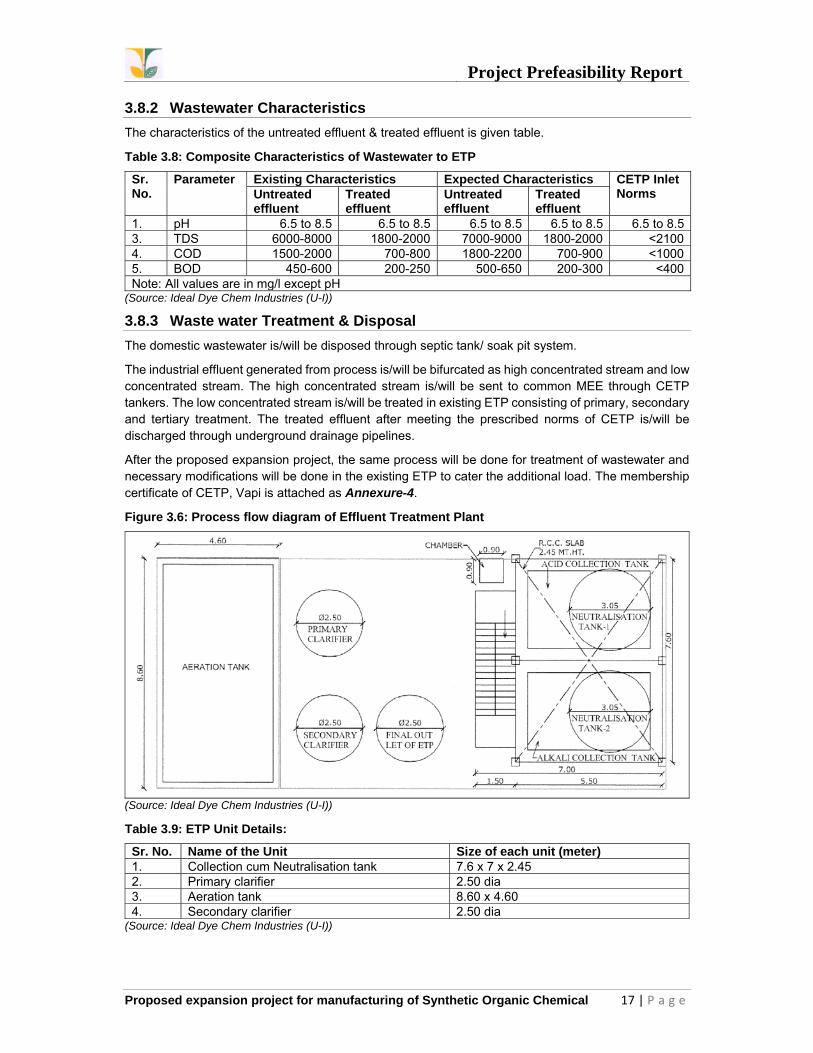
3.8.5 HAZARDOUS/NON-HAZARDOUS WASTES MANAGEMENT
Hazardous wastes are generated in the form of -----. Company has provided adequate storage area for proper storage of wastes. The copy of membership certificate of VWEMCL, Vapi is attached as Annexure-4. The detail of the hazardous waste and its management is given below in table 3.12.
Table 3.12: Hazardous and Non-hazardous waste generation, management and disposal
Type of Waste
Schedule/ Category
Source Quantity Disposal Method Existing After proposed
expansionETP Waste
35.3 ETP 180 T/annum
684 T/annum Collection, storage, transportation, disposal at TSDF-VWEMCL.
Iron Sludge
26.1 - 48 T/annum
48 T/annum Collection, storage, transportation, disposal at TSDF-VWEMCL.
Sludge from wet scrubber
36.1 Scrubber 0.12 T/annum
0.12 T/annum Collection, storage, transportation, disposal at TSDF-VWEMCL.
Used Oil 5.1 Plant & Machinery
100 liter/annum
100 liter/annum Collection, storage, transportation, disposal by selling to registered re-processors.
Discarded container/ Bags
33.3 Raw material storage
1200 Nos/annum
2500 nos/annum Collection, Storage, Decontamination.
(Source: Ideal Dye Chem Industries (U-I))
3.8.6 NOISE CONTROL
Noise generation in the process area is mainly from operation of motors, blowers, compressors, D.G. set etc. D.G. set is/will be provided with acoustic enclosures. In sections, where the noise levels are high, PPE’s will be provided to the personnel. Half yearly monitoring of noise levels at all areas will be carried out. However, Noise level generation would be limited to <80 dB within plant. No unpleasant odour will be generated from the process. Regular maintenance of equipment’s will be carried out to minimize the noise generated by the equipment.
The control measures to be taken for reduction in noise levels are as below:
Sturdy foundation to all the noise generating equipment’s will be provided. D.G. Sets is provided with acoustic enclosure. Ear Plugs and Ear muffs is/will be provided to the workers in Utility Section. Greenbelt is/will be developed.
3.9 HEALTH AND SAFETY MEASURES
The company is concerned about occupational health and safety among its work force as the man power is the biggest asset to the company. Commitment to environment, health, safety and security aspects, starting from design, technology, procurement, hiring of people, training, operation of our facilities and the management of our global distribution network.
The following key safety measures shall be implemented in the proposed project:
All the electrical fittings is/will be flameproof. Dyke wall will be constructed around tank farm to contain acids flowing into the plant in case of any
major leakage in any of the tanks. Applicable PPEs will be provided to all workers in the plant. Standard First Aid Box will be available in each department. Dedicated Occupation Health Centre will be provided to deal with any emergency.

Project Prefeasibility Report
Proposed expansion project for manufacturing of Synthetic Organic Chemical 20 | P a g e
List of emergency contact numbers will be displayed at all strategic locations. Emergency alarms will be provided at each individual unit. Emergency assembly point will be clearly marked with directional arrows from each individual unit. Mass Flow Meter will be installed for unloading/ loading of bulk tankers. Maximum handling of material with the help of stacker and forklift to minimize manual handling. Dock leveler will be installed at dispatch bay for easy loading/unloading of containers. Safety / Health records and MSDS will be maintained.
Conducting proactive risk assessment by involving employees, conducting periodic audits, using hazard identification techniques and implementation of necessary corrective and preventive actions.
3.10 ENVIRONMENTAL HEALTH & SAFETY CELL
The company is/will have a separate environment cell to keep a close watch on the performance of the pollution control equipment, emissions from the sources and the quality of surrounding environment in accordance with the monitoring program. The cell is/will also entrust with the responsibilities of regulating the safety measures inside the plant campus. The cell is/will be also responsible for maintaining the records of all data, documents and information in line within the legislative requirement.
Figure 3.7: Organogram of EHS Cell
(Source: Ideal Dye Chem Industries (U-I))

Project Prefeasibility Report
Proposed expansion project for manufacturing of Synthetic Organic Chemical 21 | P a g e
3.11 POST PROJECT MONITORING PLAN
The proposed post-project monitoring plan to ensure effective implementation of EHS Management system is given below:
Table 3.13: Environmental Monitoring Plan
Components Parameters Frequency Wastewater pH, TSS, TDS, BOD, COD Daily - At all stages
Monthly – Untreated & treatedAir-ambient PM10, PM2.5, SO2, NO2 Quarterly - within premisesAir – Stack PM, SO2, NOx Quarterly - At all stacks Noise monitoring
Noise levels in dB(A) Monthly - Main plant, utility area & boundaries
Workplace monitoring
VOCs (all solvents in use) & Lux Level Half Yearly - Inside plant
Haz. Waste management
Maintaining records of generation, receipt & disposal in Form-3
Daily
Filing of annual returns in Form-4 for haz. Waste handling
Every year by 30th June
Maintaining records of transportation in Form-9 While sending for disposalSubmission of returns of used oil in Form-13 Every year by 30th June
Renewal Consents and Authorization
Obtaining consent to operate (and renewal) under Air & Water Acts and authorization under HW rules.
90 days before expiry of validity
Water cess Filing of annual returns for cess incurred on water consumption
Every year by 30th Sept
Environmental Statement
Submission of audit statement in form-V Every year by 30th Sept
Compliance of EC conditions
Submission of compliance reports Half yearly on 1st June & 1st Dec
(Source: Ideal Dye Chem Industries (U-I))

Project Prefeasibility Report
Proposed expansion project for manufacturing of Synthetic Organic Chemical 22 | P a g e
CHAPTER – 4
SITE ANALYSIS
4.1 CONNECTIVITY
This proposed expansion project is located at Plot No.119, IInd Phase, G.I.D.C Vapi, Dist: Valsad. The Site is located in Vapi GIDC industrial estate. The land is already available. And the raw material is easily available through the easy transport via road connectivity. The nearest Railway station is Vapi railway station which is -- kms and Daman coast airbase is -- kms from the project site.
4.2 LANDFORM, LAND USE & LAND OWNERSHIP
The existing project is located at Plot No.119, IInd Phase, G.I.D.C Vapi, Dist: Valsad. The proposed expansion will be done on existing operational site.
4.3 TOPOGRAPHY
The proposed expansion is to be carried out on the existing site.
4.4 SALIENT FEATURES
The salient features of the project site are given in table 4.1.
Table 4.1: Salient Features of the Project Site
Particulars DetailsCo-ordinates Latitude: 20°21'37.35"N, Longitude: 72°55'41.99"ETaluka/ Tehsil PardiDistrict ValsadNearest Water body Damanganga River ≈ 2.71 (SW)Nearest Highway NH8 ≈ 0.86 (NW) Nearest Railway station & Railway line Vapi Railway Station ≈ 2.54 (NW) Nearest Airport/ Airbase Daman & Diu ≈ 11.85 (NW)State/ National borders Dadra & Nagar Haveli ≈ 2.12 (SE) Protected Area/ Sanctuaries None within 10 km radial periphery CRZ applicability NASeismicity Seismic Zone – III (Moderate)Note: All the above mentioned distances are the aerial distance from the project site.
(Source: Google Earth)
4.5 EXISTING INFRASTRUCTURE
The proposed expansion is to be carried out in the existing site. The company has the required infrastructure. Necessary modifications will be done.
4.6 SOIL CLASSIFICATION
The catchment area of the proposed project site consists of flat topped, highly dissected plateaus and dyke ridges running in a west to east direction. The Main River (Daman Ganga) in the catchment area flows in incised meanders forming steep geomorphologic ally ‘V’ shaped valleys with steep sides. The entire catchment has a rectangular and trellis pattern of drainage depicting the influence of the structures on the drainage development. The piedmonts at the base of the steep plateaus and dyke ridges are covered with thin soils, which support agriculture in very few areas. The river valley, wherever flat, has good quality soil and is mostly cultivated based on the availability of water. The river valley fills with thick alluvium provides the only area for cultivation.

Project Prefeasibility Report
Proposed expansion project for manufacturing of Synthetic Organic Chemical 23 | P a g e
4.7 CLIMATE& METEROLOGY
The year can be divided into four seasons. Climate is warm and dry from mid-March to June, during season of summer, climate remains warm and dry, while during rainy season, from mid-June to end of September, climate is humid and pleasant. From October to November mild warm climate prevails, and from December to February climate is cold.
The Table 4.2 indicates the summary of meteorological pattern at the nearest observatory of IMD, Dahanu published by IMD.
Table 4.2: Summary Meteorological Data at nearest IMD Station –Dahanu
Month Temperature (oC)
Relative Humidity
(%)
Cloud Cover (Oktas)
Mean Wind
Speed (km/hr)
Pre-dominant
Wind Direction
Rainfall (mm)
Max. Min. Mor. Eve. Max. Min. January 32.5 13.2 66 67 1.1 1.0 9.5 N 0.1February 33.1 14.0 64 66 0.9 0.8 10.1 NW 0.1March 35.2 17.1 66 64 1.2 0.9 11.1 NW 0.1April 35.8 21.2 73 67 1.9 1.2 12.1 W 0.2 May 35.7 24.1 75 70 3.2 2.1 14.1 W 9.4 June 35.3 23.4 83 77 5.7 5.4 16.3 SW 400.3July 32.8 23.1 88 84 6.8 6.8 20.2 SW 665.8August 31.6 23.2 88 83 6.9 6.7 20.4 SW 464.2September 32.6 22.5 86 77 5.2 4.8 12.3 W 254.2 October 35.5 20.2 75 70 2.4 2.2 8.5 NW 35.3 November 35.1 17.3 66 69 1.6 1.7 8.1 E 18.9 December 33.8 14.5 66 70 1.4 1.5 8.3 E 2.8Seasonal Average Values Period Temperature
(oC) Relative
Humidity (%) Cloud Cover
(Oktas) Mean Wind
Speed (km/hr)
Avg. PDW Direction
Total Rainfall
(mm) Avg. Max.
Avg. Min.
Avg. Mor.
Avg. Eve.
Avg. Max.
Avg. Min.
Summer 35.6 26.2 71 67 2.1 1.4 12.4 W 9.7 Winter 33.1 13.9 65 68 1.1 1.1 9.3 E 3.0Monsoon 33.0 23.0 87 80 6.1 5.9 17.3 SW 1784.5Post monsoon 35.3 18.7 70.5 69.5 2 2 8.3 NW/E 54.2Note: Winter: December, January & February, Summer: March, April & May, Monsoon: June, July, August & September, Post monsoon: October & November
(Source: Climatological tables of observations in India (1961-1990), IMD)
4.7.1 TEMPERATURE
The summer season from March to May is a one of continuous increase in temperatures which decreases during monsoons, increases slightly during the post-monsoon season and again decreases during the winter. May is generally the hottest month with the mean daily maximum temperature recorded at 35.70C and mean daily minimum temperature recorded at 24.10C. January is the coldest month with the mean daily maximum temperature as 32.50C and mean daily minimum temperature observed as 13.20C.
4.7.2 HUMIDITY
The climate of the region is characterized by a humid summer because of the closeness to coastline. Humidity is usually high during the monsoon months, with average relative humidity generally exceeding 80%. Humidity decreases gradually during the post-monsoon months and for rest of the year i.e. the period of December to April, the average relative humidity ranges around 50-70%.

Project Prefeasibility Report
Proposed expansion project for manufacturing of Synthetic Organic Chemical 24 | P a g e
4.7.3 RAINFALL
About 95% of the annual rainfall is received during the southwest monsoon season i.e. from June to September, July being the month with highest rainfall. The total annual rainfall observed from the historical data of year 1951-1980 is 1784.5 mm.
4.7.4 WIND PATTERN
The annual resultant vector for wind direction shows winds blowing from WSW. During summers and monsoon, the winds blow mostly from the sea i.e. the SW or WSW direction. The post-monsoon & winter seasons experience a change in direction, with the winds blowing from NE, ENE or NNE. The wind speed is high during monsoon and post monsoon seasons, slightly moderate during summer and winter seasons.
4.8 SOCIAL INFRASTRUCTURE
The infrastructure available in the study area denotes the economic wellbeing of the region. There are about 70 villages and 7 Town in the Pardi taluka.
4.8.1 EDUCATIONAL FACILITIES
As per census of India, 150 Primary school, 20 Secondary School and 11 senior secondary school. There were not Middle School and Training institute found in Pardi Taluka.
4.8.2 MEDICAL FACILITIES
Out of the 70 villages, hospitals were not available in all villages, Primary health centres in 6 villages, Primary health sub centre in 58 villages.

Project Prefeasibility Report
Proposed expansion project for manufacturing of Synthetic Organic Chemical 25 | P a g e
CHAPTER – 5
PLANNING BRIEF
5.1 PLANNING CONCEPT
The existing project is located at Plot No.119, IInd Phase, G.I.D.C Vapi, Dist: Valsad. The proposed expansion will be done on existing operational site.
5.2 POPULATION PROJECTION
The average household size is around 4 to 5. The Sex ratio is very less.
Table 5.1: Distribution of population
Sr. No. Particulars Observed values in 10 km Radius1 Total Population 2925272 No. of Households 672713 Avg. household size (persons) 4-54 Male population 1556685 Male population (in %) 536 Female population 1368597 Female population (in %) 478 Sex ratio 879
(Source: Primary Census Abstract – Census of India, 2011)
5.3 AREA STATEMENT
Total land area is 2090 m2. Necessary modifications will be done in the existing site. No additional land will be required for the proposed expansion.
5.4 ASSESMENT OF INFRASTRUCTURE DEMAND (PHYSICAL & SOCIAL)
For proposed expansion project the company will acquire some machinery so there will be some demand of change in physical infrastructure and social infrastructure. As manpower requirement for the proposed project shall be locally fulfilled, employment generation will lead to additional benefits to social infrastructure.
5.5 AMENITIES/FACILITIES 5.5.1 DRINKING WATER FACILITIES
As per the Census 2011, Tap water is available in 69 villages. 68 had Wells, 40 villages had tanks/ Ponds/ Lakes and 69 had hand pumps. 42 Villages had River or canal passing. Power supply was also available in all the villages.
5.5.2 POWER SUPPLY FACILITIES
As per census 2011, all the villages have power supply facilities in the study region.
5.5.3 COMMUNICATION & BANKING FACILITIES
Communication facilities like Post and telegraph, telephones exist in almost all the villages as per the 2011 census.
5.5.4 TRANSPORT FACILITIES
Bus service is available in the pardi taluka and is the most preferable mode of transport in the region. The villages are well connected with the State Highways. National Highway-8 also passes from Vapi. The Western railway line between Bombay to Ahmedabad passes from the pardi taluka and Vapi Town has a railway station on the same.

Project Prefeasibility Report
Proposed expansion project for manufacturing of Synthetic Organic Chemical 26 | P a g e
CHAPTER – 6
PROPOSED INFRASTRUCTURE
6.1 INDUSTRIAL AREA
The total area of the plot is 2090 m2 out of which greenbelt area of the plant is 500 m2, which is approx. 23.9%.
6.2 RESIDENTIAL AREA
In the said proposal no Residential area has been proposed for workers and/or for staff.
6.3 GREENBELT
Total greenbelt area is 500 m2, which is approx. 23.9% total plot area.
6.4 SOCIAL INFRASTUCURE
Existing infrastructure will be sufficient to accommodate the existing load from the proposed project which is very low.
6.5 CONNECTIVITY
As described in chapter-4.
6.6 DRINKING WATER MANAGEMENT
The source of drinking water is/ will be GIDC water supply.
6.7 SEWERAGE SYSTEM
Domestic wastewater generated from the existing and proposed expansion is/will be disposed of through septic tank/soak pit system.
6.8 INDUSTRIAL WASTE MANAGEMENT
Industrial Effluent will be treated in the Effluent Treatment Plant at the site and after confirming the CETP inlet norms it will be sent to CETP.
6.9 SOLID WASTE MANAGEMENT
Details of solid waste generation are given in table 3.8.5 at chapter-3.
6.10 POWER REQUIREMENT & SOURCE OF SUPPLY
Details of power requirement & source of supply are given at 3.7.3 at chapter-3.

Project Prefeasibility Report
Proposed expansion project for manufacturing of Synthetic Organic Chemical 27 | P a g e
CHAPTER – 7
REHABILITATION &RESETTLEMENT (R &R) PLAN
7.1 POLICY TO BE ADOPTED
The proposed expansion project is to be developed in the existing unit land which is designated for industrial use. Hence, no displacement of any population is proposed for the project. Therefore, detailed Social Impact Assessment studies or R&R action study has not been proposed.

Project Prefeasibility Report
Proposed expansion project for manufacturing of Synthetic Organic Chemical 28 | P a g e
CHAPTER – 8
PROJECT SCHEDULE & COST ESTIMATES 8.1 TIME SCHEDULE OF THE PROJECT
The installation/ construction will be started after getting approval for Environmental Clearance and NOC from authorities.
8.2 ESTIMATED PROJECT COST
The estimated project cost for the proposed expansion will be approximately 6.70 Crores.
Table 8.1: Total Capital Cost Projection
Sr. No. Purpose Capital Cost (Rs in Cr)1. Land 02. Building 1.003. Plant & Machinery 3.154 Electrification and Administrative set-up 0.255. Environment Protection (including ETP, APCD etc.) 1.00
MEE 0Air pollution control device 0.05Env. Monitoring expenses 0.05
6. Safety instruments 0.107. Chartered services/ Government fees (excise, GST & other
taxes) 1.00
8. Green belt development 0.05 TOTAL 6.70

Project Prefeasibility Report
Proposed expansion project for manufacturing of Synthetic Organic Chemical 29 | P a g e
CHAPTER – 9
ANALYSIS OF PROPOSAL
9.1 FINANCIAL & SOCIAL BENEFITS
M/s. Ideal Dye Chem Industries (Unit-I) is located at Plot No.119, IInd Phase, G.I.D.C Vapi, Dist: Valsad.
The proposed expansion project will employ additionally 80 persons. The man-power required for the proposed project will be employed from local areas.

Annexures

Annexure-1 Existing CC&A


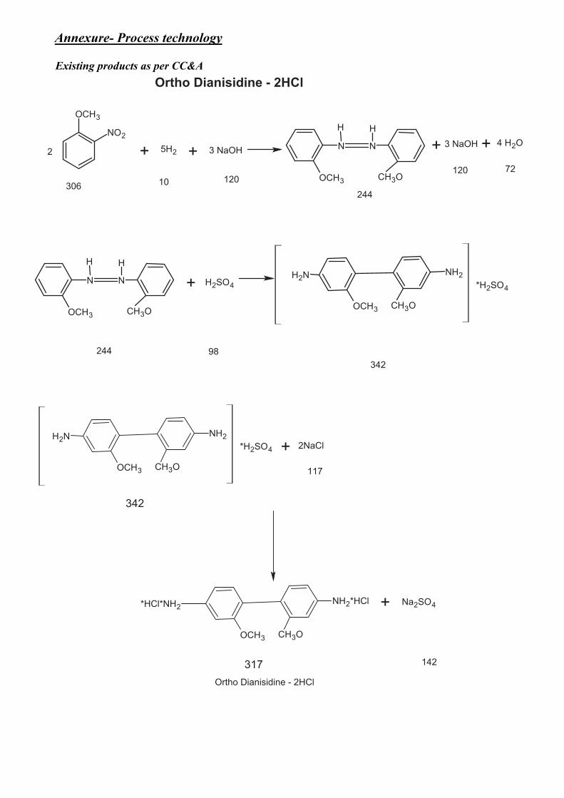
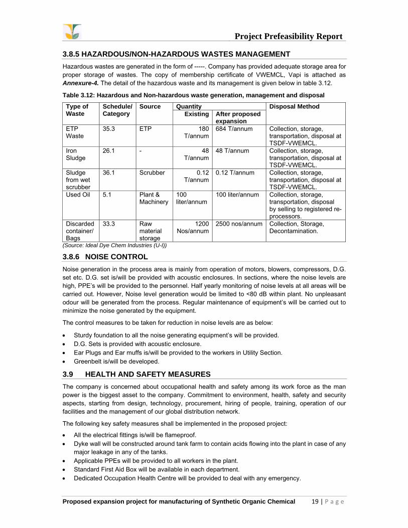
Ortho�Dianisidine�-�2HCl
OCH3
NO2
2 + 5H2 3�NaOH4�H2O
+ N N
HH
CH3OOCH3
3�NaOH ++
244306 10 120
120 72
N N
HH
CH3OOCH3
+ H2SO4
OCH3
H2N NH2
CH3O
*H2SO4
OCH3
H2N NH2
CH3O
*H2SO4 + 2NaCl
OCH3
*HCl*NH2NH2*HCl
CH3O
+ Na2SO4
Ortho�Dianisidine�-�2HCl
244 98342
342
117
317 142
Annexure- Process technology
Existing products as per CC&A

Ortho dianisidine-2HCl
Material Balance All values in kg
Ortho Nitro Anisol 1000.0Caustic 910.0Hydrogen Gas 55.0Toluene 2000.0Water 2000.0
5965.0Toluene Recovered 1940.0Losses 60.0Effluent to ETP 2208.0
1757.0
1757.0Sulphuric Acid (98%) 1200.0Sodium Chloride Salt 200.0Water 5750.0
8907.0
8907.0Effluent to ETP 7021.0
1886.0Drying Loss 1000.0
886.0
Filtration
Drying
Product886.0
Reactor
Filtration
Wet Cake
Reactor
Isolation by Salting

+ Cl2
CH3
NO2
CH3
NO2
Cl
CH3
NH2
Cl
CH3
NO2
Cl
+ 4�Fe 4�Fe(OH2)+
CH3
NH2
Cl
+ H2SO4
CH3
NH2
Cl
SO3H
2B�Acid
Paranitrotoluene137 71 171.5 36.5
171.5 141.5
2-Chloro-4-Nitro�toluene
141.5 221.5
2B�Acid2-Chloro-4-toluidine
2-Chloro-4-toluidine2-Chloro-4-Nitro�Toluene
HCl+
+H2O
1898

2B AcidMaterial Balance All values in kg
Paranitroluente 682 HCl gas to scrubber 220Liquid chloride 350
Iron 1350
Iron Sludge to TSDF 1520
Sulphuric acid (98%) 600
Soda ash 125Caustic soda flakes 85Water 1000
Hydrochloric acid (30-35% soln) 600
Wastewater to ETP 1950
Losses 2
Purification
1100
1102
3052
3052
2452
Filtration
Reduction
Chlorination
Product
Drying
Filtration
isolation
642
2162
812
1242
Sulphonation

+ H2SO4 H2O+
Paratoludine Sulphuric�acid 4B�Acid
CH3
NH2
107 98 18
CH3
NH2
SO3H
187
4B�ACID

4B AcidMaterial Balance All values in kg
Orthodichloro Benzene 2500Paranitro Toluene 1000Sulphuric Acid (98%) 1000
Soda Ash 300 Orthodichloro Benzene (Recovered) 2400Caustic soda flakes 200 Losses 100Water 1000
Hydrochloric acid (30-35% soln) 1500
Wastewater to ETP 3380
Losses 20
Filtration
5000Isolation
3500
Purification
1600Product
1600Drying
1620
Reactor
4500

Tetra�Chloro�Benzidine
NO2
Cl
Cl
2 + 5H2 + NaOHCl
Cl
N N
H HCl
Cl
4H2O+
2,�5�Dichloro�Nitro�Benzene
324 322
NH2
Cl
Cl Cl
Cl
NH2
Cl
Cl
N N
H H
Cl
Cl
322 395
Tetra�Chloro�Benzidine�-�2HCl
NaOH+
2HCl+ 2HCl
73
NH2
Cl
Cl Cl
Cl
NH2
395
2HCl + Na2CO3 NH2
Cl
Cl Cl
Cl
NH2
Tetra�Chloro�Benzidine
Tetra�Chloro�Benzidine�-�2HCl
Proposed additional products

Tetra Chloro Benzidine-2HCl
Material Balance All values in kg
2, 5 Dichloro Nitro Benzene 1230Caustic soda 152Hydrogen gas 40Toluene 2000
1900 Toluene recovered100 Losses
Hydrochloric acid (30-35%) 280Water 1000
1202 Wastewater to ETP
1422.0
Filtration
3422
Reactor
1500.0Product
1500.0Filtration
2702.0Reactor
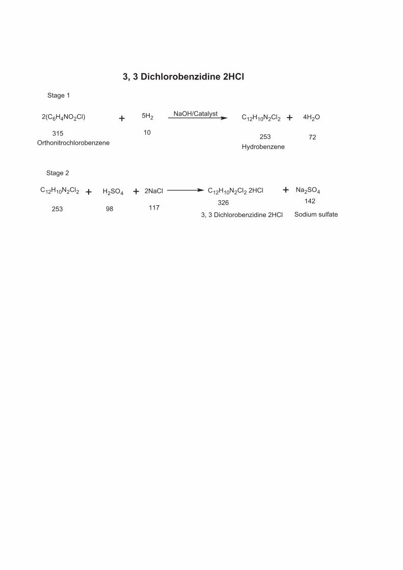
2(C6H4NO2Cl) + 5H2 C12H10N2Cl2NaOH/Catalyst + 4H2O
Stage�1
Stage�2
315 10 253 72Hydrobenzene
C12H10N2Cl2 H2SO4 2NaCl C12H10N2Cl2�2HCl Na2SO4
3,�3�Dichlorobenzidine�2HCl Sodium�sulfate
14232611798253
Orthonitrochlorobenzene
+ + +
3,�3�Dichlorobenzidine�2HCl

3,3 dichlorobenzidine-2HClMaterial Balance All values in kg
Ortho Nitro Chloro Benzene (ONCB) 4536.0Caustic 212.0Hydrogen Gas 54.0Toluene 2500.0 Water 4000.0
11302.0Toluene Recovered 2350.0Effluent to CMEE 5000.0Losses 150.0
3802.0
3802.0Sulphuric Acid (98%) 1322.0
5124.0Sodium Chloride Salt 1510.0
6634.0Water 42000.0 Effluent to ETP 40134.0
8500.0Drying Loss 4100.0
4400.0
Drying
Product4400.0
Reactor
Filtration
Wet Cake
Reactor
Isolation by Salting
Filtration

CH3
NO2
4H2NaOH
+ + 4H2O
+ +H2SO4 2HCl
CH3
NH2HClNH2
CH3
HCl
2
ORTHOTOLUDINE
274 8 210 72
210 98 73 285
H2SO4+
CH3
N
CH3
N
CH3
N
CH3
NH2
CH3
NH2HClNH2
CH3
HCl
285
NaOH+
CH3
NH2H2N
CH3
+2HCl 2H2O+

Ortho Toludine-2HCl
Material Balance All values in kg
O-Nitro Toluene 290Hydrogen Gas 40Caustic Soda 50Water 1000.0
1380.0
Effluent to ETP 1129.0
251.0
251.0Sulphuric Acid (98%) 200.0Hydrochloric acid (30-35% soln) 100.0
551.0
551.0Effluent to ETP 245.0
306.0Drying Loss 6.0
300.0
Filtration
Drying
Product300.0
Reactor
Filtration
Wet Cake
Reactor
Isolation by Salting


Scanned by CamScanner