Efficiency Enhancement Projects Sabarmati Thermal Power...
39
Page 1 of 39 Efficiency Enhancement Projects Sabarmati Thermal Power Station, AMGEN Torrent Power Limited Index Si No. Description Page 01 Note on Efficiency Enhancement Projects 02 02 Note on ESP retrofit work 09 03 Past Performance data 11 04 GPCB Measurement data 24 05 Consent for Operation‐‐ 1986 27 06 NOC for F and C unit 32 07 Consent for Operation‐2013 36
Transcript of Efficiency Enhancement Projects Sabarmati Thermal Power...

Page 1 of 39
Efficiency Enhancement Projects Sabarmati Thermal Power Station, AMGEN
Torrent Power Limited
Index
Si No. Description Page
01 Note on Efficiency Enhancement Projects 02
02 Note on ESP retrofit work 09
03 Past Performance data 11
04 GPCB Measurement data 24
05 Consent for Operation‐‐ 1986 27
06 NOC for F and C unit 32
07 Consent for Operation‐2013 36

Page 2 of 39
Note on Efficiency Enhancement Projects Sabarmati Thermal Power Station,
AMGEN, Torrent Power Limited
Preamble:
Torrent Power Limited (TPL), a part of the Torrent Group has the license to generate, transmit
and distribute electricity in app 380 sq. km. area covering entire Ahmedabad city and Capital
city of Gujarat state‐Gandhinagar. TPL have Coal Generating Stations in Ahmedabad (known as
AMGEN) comprising of following units with total installed capacity of 422 MW as on date. The
efficiency enhancement is carried out in phase manner in 110 mw units.
Unit Existing Capacity in MW
Date of commissioning
Date of enhancement in
capacity
New capacity in MW
C 60 12‐04‐1997 ‐ 60
D 110 12‐10‐1978 01‐04‐2004 120
E 110 31‐12‐1984 05‐11‐2013 121
F 110 28‐09‐1988 14‐05‐2013 121
AMGEN 390 422
Brief on Power Generation Processes at different Units at AMGEN ‐ Sabarmati:
Sabarmati TPS uses a blend of Indian and Imported coal as fuel. Coal is received at the power
station through rail wagons and is unloaded at site by wagon tippler. Subsequently coal is
crushed in a coal crusher to fine grain as per the required size from where it is transferred to
the station bunkers of Units – C, D, E & F by means of a coal conveyor belts. The coal from the
bunkers is fed to the steam generators after being pulverized in the coal mills.
The steam generators of 110 MW are tangentially fired; balance draught, natural circulation,
radiant reheat type, and dry bottom having bowl mills with direct firing arrangement of
pulverised coal.

Page 3 of 39
Key parameters of steam generators working are listed below:
Type of Steam Generator BHEL make corner fired type
Steam Generator Parameters (BMCR)
Main Steam ‐ 375T/hr @ 138 Kg/cm2(g) at 540oC
Feed water temp 241oC
Re‐heater inlet ‐ 313.5 T/hr @ 34kg/cm2(g) at 365oC
Re‐heater outlet ‐ 313.5 T/hr @ 32kg/cm2(g) at 540oC
Number of Oil Elevation Three (3)
Number of Coal Levels Six (6)
Re‐heat steam temp. control Burner tilting as a primary
In the steam generator, water is heated by the heat generated while burning coal in the furnace
and is converted into a high pressure steam. This high pressure steam is fed to the steam
turbine. The original steam turbine has the following key parameters.
Electrical output : 110 MW
Nominal speed : 3000 rpm
No. of cylinders : 3, namely High Pressure (HP), Intermediate Pressure (IP) and Low Pressure
(LP)
Live steam pressure at HP Turbine Inlet : 130 atm (g)
Live steam temperature at HP Turbine Inlet : 535°C
Steam temperature at IP Turbine inlet : 535°C
The steam Turbine is coupled with the Alternator to convert Mechanical Power of the Turbine
in to Electrical Power at the Output.
The Electrical Power (electricity) generated in the Alternator is fed to the 132 kV Switchyard via
Step up Transformer which is then transmitted to the grid through 132kV switchyard.
Brief on R&M work at AMGEN – Sabarmati
TPL has undertaking Renovation & Modernization (R&M) activities at 110 MW Units (For all
three units in phase manner) at AMGEN – Sabarmati as a part of its initiative to produce power
in a more environmental friendly and economic manner.
Following are the Major activities included under R&M work for all three 110 MW Units.
Improvement in Turbine Cycle Efficiency & efficient control of Steam Turbines.
o Retrofitting the existing turbine components (turbine internals) with new state of
the art efficient turbine components. The turbine rotors & inner casings shall be
replaced where as the existing outer casings will be retained.

Page 4 of 39
o Replacement of Gland Sealing & Leak OFF System
o Refurbishment / re‐babitting of turbine bearings to suit the requirements of the
retrofitted turbine rotors.
o Replacement of turbine control system with state of the art Electro Hydraulic
Turbine Control system (EHTC) to achieve better control of TG set.
o Replacement of turbine drain system to facilitate Automatic Turbine Run‐up System
(ATRS)
o These activities helped in improvement of turbine efficiency.
o D unit 3rd ESP path installed and commissioned for improving the overall ESP system
performance. While E and F unit ESP system retrofit by increases height of ESP
system results in higher area available for ESP system. Also the old ash collection
mechanism replaced with new and efficient system
Technical Description of the new System: Turbine.
In order to reduce the emission of green house gases, TPL has carry out Renovation &
Modernization (R&M) work at existing 110 MW Units at AMGEN – Sabarmati Power Station as a
proactive step towards protection of environment. Under these projects, TPL changed the
turbine internals. After this retrofit, there is no change in pollution load. Incidentally, the unit
capacity was also enhanced to 121 MW from the existing rating of 110 MW.
The modification of steam turbine consists of replacement of turbine internals (Rotors & inner
casings) with state of the art energy efficient turbine components. The original gland sealing &
leak‐off system has replaced to suit with the new turbine components. The original bearings
have modified & re‐babitted to match with requirements of retrofitted turbines. The turbine
drain system components have replaced to match requirements of new turbine controls & auto
run‐up system.
High Pressure Turbine
The HP turbine is of similar design as the original one. The original design with the Curtis type
control stage and eight impulse stages have replaced by the A‐type control stage and nine other
impulse stages.
The new HP rotor is fitted with improved specific blades. The blades are fixed to the rotor by
"T" clamped roots or fork type pinned roots and bound in bundles by shrouds. These shrouds
bind the blades to increase the dynamic stiffness, and are also used for forming the peripheral

Page 5 of 39
sealing of the moving blades. The HP rotor is machined from a solid forging including a coupling
flange for its mutual connection to the IP rotor. The connections among the turbine rotors are
made by means of rigid couplings with fitted bolts.
Intermediate Pressure Turbine
The IP turbine is of similar design as the original one with the same number of stages. Some of
the salient features are as below:
a. The new rotor is fitted with improved specific blades. The blades are fixed to the rotor by
"T" clamped roots or fork type pinned roots and they are bound in bundles by shrouds.
These shrouds bind the blades to increase the dynamic stiffness, but they are also used for
forming the peripheral sealing of the moving blades. The rotor is machined from a solid
forging including coupling flanges for its mutual connection to the HP and LP rotors. The
connections among the turbine rotors are made by means of rigid couplings with fitted
bolts.
b. The inner casing including sealing rings for two pipes of steam inlets to casing, carriers,
improved gland casings along with gland rings, the nozzle box of improved design used.
c. The diaphragms have placed in the inner casing and in two new carriers; last two
diaphragms has placed in the original outer casing. All the diaphragms have made of steel
and the nozzle cascades fixed by means of pins in the diaphragms discs and rims. The
diaphragms have mounted in the inner casing and two carriers. New upgraded nozzles 3D
profiles, more perfectly streamlined, optimised from the point of minimization of
aerodynamic losses have used. The new inter stage sealing arrangements (honeycomb type)
has form parts of the diaphragms (guide wheels).
d. All shaft glands are of an axial flow labyrinth type. The labyrinths rings are mounted in the
seal casings or in the diaphragms. Rebounding labyrinth rings made from stainless material
is used. These rings are divided into six parts; they are pressed into their operating position
by springs and by the pressure of the steam. The teeth are turned on the labyrinth rings. On
the individual rings there are alternate higher and lower teeth. A true labyrinth forms the
seal. Inter stage‐sealing arrangements are also provided.
e. The original outer casing has repaired and retained.

Page 6 of 39
Low Pressure Turbine
The LP turbine is of similar design as the original one. The original number of stages 2 x 4 is
retained. Some of the salient features are as below:
a. The original front and rear exhaust casings and the middle casing is used and retained. The
solid forging rotor including coupling flanges, moving blades, diaphragms including labyrinth
rings and the modified gland casings for both front and rear outer glands along with gland
rings used are new ones.
b. The new rotor is fitted with improved specific blades. Moving blades of all stages are fixed
to the rotor by fork type pinned roots. Moving blades are bound in bundles by shrouds.
These shrouds bind the blades to increase the dynamic stiffness, but they are also used for
forming the peripheral sealing of the moving blades. The moving blades of the last two
stages are designed with twisted transonic profiles, which enable to achieve higher
efficiency. Last two moving blades are very rigid, free standing, without any lacing wire and
it gives the possibility to operate continuously in range 47.5 to 51.5 Hz. Erosion protection
of the moving blades fitted to the last stage is achieved by using a surface hardening
process during manufacture. The rotor is machined from a solid forging including coupling
flanges for its mutual connection to the IP rotor and generator rotor. The connections
among these rotors are made by means of rigid couplings with fitted bolts.
c. First two diaphragms are made of steel, and the nozzle cascades are fixed by means of pins
in the diaphragms discs and rims. Other two diaphragms are made of steel, and the nozzle
cascades are welded to the diaphragms discs and rims. The diaphragms are divided in the
horizontal axis to form upper and lower halves. They are mounted in the middle casing,
centre‐line supported, to maintain precise inter‐stage sealing clearances.
d. All shaft glands are of an axial flow labyrinth type. The labyrinths rings are mounted in the
seal casings or in the diaphragms. Rebounding labyrinth rings made from stainless material
are used. These rings are divided into six parts; they are pressed into their operating
position by springs and by the pressure of the steam. Teeth of the same height are used
against a smooth rotor ‐ untrue labyrinth. Inter stage‐sealing arrangements are also
provided.

Page 7 of 39
The Turbine rotor blade profile and advanced seals which improves the efficiency.
Indicative assembly of a 3 casing turbine in the existing outer casings is given below:

Page 8 of 39
Top view of final assembly work of new Turbine rotor.
Final Assembled Turbine after up rating work.

Page 9 of 39
Note on ESP retrofit work done during the Turbine R & M work.
ESP Up‐gradation at D STN
• Additional ESP Path containing 5 fields added in parallel to existing two paths
• Original ESP had 4 fields per path i.e. total 8 fields, after up‐gradation total field 13
Major work carried out
• Construction of new path in parallel to existing paths
• Construction of new ESP control room
• Replacement of Power & control panels with cabling
• New EPIC‐III controllers for all the 13 fields
• Extension of ash handling system for new ESP path
• Overhauling of Existing ESP paths including replacement of warn out internals.
New ESP 3rd Path. ESP control room with latest controls.

Page 10 of 39
ESP Up‐gradation at E and F STN
Major works.
• Replacement of all internals of existing ESP paths
• Filling of Dummy Fields
• Total fields after dummy field filling – 14
• Increase in height of Existing ESP by @ 1.6 mtr.
• Replacement of ESP controllers with EPIC‐III controllers
• Replacement of power & control panels with cabling.
E and F unit ESP Retrofitting work photograph.

Page 11 of 39
Past Performance data
As explained above Torrent Power Limited‐Sabarmati plant capacity increases from 390 MW to
422 MW without increase in the input parameters for the turbine. Also there is no change in
the pollution load by improving the Turbine efficiency. The environment parameters like Stack
emission, Air quality etc. remains well within the approved limit and no major upward change
observed in the emission parameters after retrofitting work. The emission parameters for the
last five years as measured and submitted by schedule‐1 auditor in the Annual Audit report is
tabulated as under for ready reference.
Emission.
Year 2011 (Auditor—ATIRA)
Stack Emission
ROUND – 1 Date: 28‐29/04/2011
Stack Side SPM NOx
GPCB Limit 100 mg/Nm3 50 ppm
C Stack Left 88 0.59
Right 52 0.65
D Stack Left 56 0.46
Right 48 0.45
E Stack Left 38 0.17
Right 52 0.24
F Stack Left 42 0.26
Right 46 0.21
Page 12 of 39
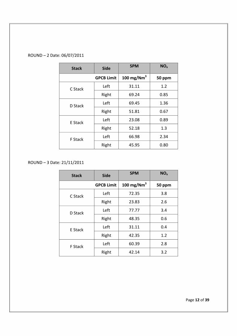
ROUND – 2 Date: 06/07/2011
Stack Side SPM NOx
GPCB Limit 100 mg/Nm3 50 ppm
C Stack Left 31.11 1.2
Right 69.24 0.85
D Stack Left 69.45 1.36
Right 51.81 0.67
E Stack Left 23.08 0.89
Right 52.18 1.3
F Stack Left 66.98 2.34
Right 45.95 0.80
ROUND – 3 Date: 21/11/2011
Stack Side SPM NOx
GPCB Limit 100 mg/Nm3 50 ppm
C Stack Left 72.35 3.8
Right 23.83 2.6
D Stack Left 77.77 3.4
Right 48.35 0.6
E Stack Left 31.11 0.4
Right 42.35 1.2
F Stack Left 60.39 2.8
Right 42.14 3.2
Page 13 of 39
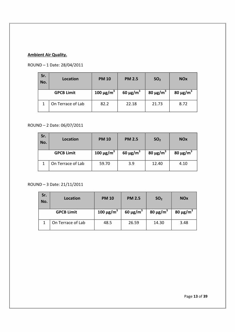
Ambient Air Quality.
ROUND – 1 Date: 28/04/2011
Sr.
No. Location PM 10 PM 2.5 SO2 NOx
GPCB Limit 100 µg/m3 60 µg/m3 80 µg/m3 80 µg/m3
1 On Terrace of Lab 82.2 22.18 21.73 8.72
ROUND – 2 Date: 06/07/2011
Sr.
No. Location PM 10 PM 2.5 SO2 NOx
GPCB Limit 100 µg/m3 60 µg/m3 80 µg/m3 80 µg/m3
1 On Terrace of Lab 59.70 3.9 12.40 4.10
ROUND – 3 Date: 21/11/2011
Sr.
No. Location PM 10 PM 2.5 SO2 NOx
GPCB Limit 100 µg/m3 60 µg/m3 80 µg/m3 80 µg/m3
1 On Terrace of Lab 48.5 26.59 14.30 3.48
Page 14 of 39
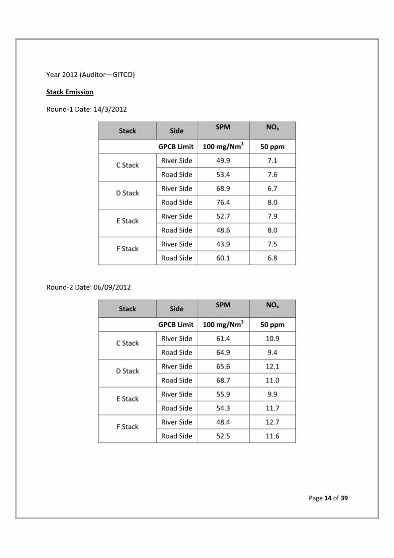
Year 2012 (Auditor—GITCO)
Stack Emission
Round‐1 Date: 14/3/2012
Stack Side SPM NOx
GPCB Limit 100 mg/Nm3 50 ppm
C Stack River Side 49.9 7.1
Road Side 53.4 7.6
D Stack River Side 68.9 6.7
Road Side 76.4 8.0
E Stack River Side 52.7 7.9
Road Side 48.6 8.0
F Stack River Side 43.9 7.5
Road Side 60.1 6.8
Round‐2 Date: 06/09/2012
Stack Side SPM NOx
GPCB Limit 100 mg/Nm3 50 ppm
C Stack River Side 61.4 10.9
Road Side 64.9 9.4
D Stack River Side 65.6 12.1
Road Side 68.7 11.0
E Stack River Side 55.9 9.9
Road Side 54.3 11.7
F Stack River Side 48.4 12.7
Road Side 52.5 11.6
Page 15 of 39
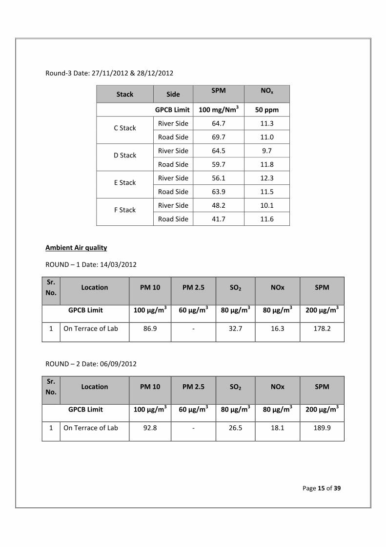
Round‐3 Date: 27/11/2012 & 28/12/2012
Stack Side SPM NOx
GPCB Limit 100 mg/Nm3 50 ppm
C Stack River Side 64.7 11.3
Road Side 69.7 11.0
D Stack River Side 64.5 9.7
Road Side 59.7 11.8
E Stack River Side 56.1 12.3
Road Side 63.9 11.5
F Stack River Side 48.2 10.1
Road Side 41.7 11.6
Ambient Air quality
ROUND – 1 Date: 14/03/2012
Sr.
No. Location PM 10 PM 2.5 SO2 NOx SPM
GPCB Limit 100 µg/m3 60 µg/m3 80 µg/m3 80 µg/m3 200 µg/m3
1 On Terrace of Lab 86.9 ‐ 32.7 16.3 178.2
ROUND – 2 Date: 06/09/2012
Sr.
No. Location PM 10 PM 2.5 SO2 NOx SPM
GPCB Limit 100 µg/m3 60 µg/m3 80 µg/m3 80 µg/m3 200 µg/m3
1 On Terrace of Lab 92.8 ‐ 26.5 18.1 189.9

Page 16 of 39
ROUND – 3 Date: 27/11/2012
Sr.
No. Location PM 10 PM 2.5 SO2 NOx SPM
GPCB Limit 100 µg/m3 60 µg/m3 80 µg/m3 80 µg/m3 200 µg/m3
1 On Terrace of Lab 91.3 54.7 24.1 22.0 ‐
Year 2013 (Auditor—GITCO)
Stack Emission
Round‐1 Date: 17/05/2013
Stack Side SPM NOx
GPCB Limit 100 mg/Nm3 50 ppm
C Stack River Side 59.8 6.9
Road Side 61.2 7.3
D Stack River Side 65.7 8.6
Road Side 68.7 8.1
E Stack River Side 61.3 8.9
Road Side 57.8 8.6
F Stack River Side 51.7 8.8
Road Side 52.6 8.5
Page 17 of 39
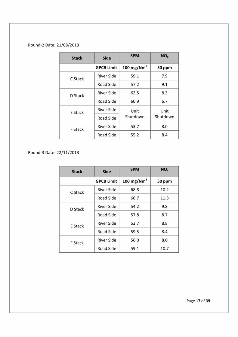
Round‐2 Date: 21/08/2013
Stack Side SPM NOx
GPCB Limit 100 mg/Nm3 50 ppm
C Stack River Side 59.1 7.9
Road Side 57.2 9.1
D Stack River Side 62.5 8.3
Road Side 60.9 6.7
E Stack River Side Unit
Shutdown Unit
Shutdown Road Side
F Stack River Side 53.7 8.0
Road Side 55.2 8.4
Round‐3 Date: 22/11/2013
Stack Side SPM NOx
GPCB Limit 100 mg/Nm3 50 ppm
C Stack River Side 68.8 10.2
Road Side 66.7 11.3
D Stack River Side 54.2 9.8
Road Side 57.8 8.7
E Stack River Side 53.7 8.8
Road Side 59.5 8.4
F Stack River Side 56.0 8.0
Road Side 59.1 10.7

Page 18 of 39
Ambient Air Quality
ROUND – 1 Date: 17/05/2013
Sr.
No. Location PM 10 PM 2.5 SO2 NOx
GPCB Limit 100 µg/m3 60 µg/m3 80 µg/m3 80 µg/m3
1 On Terrace of Lab 94.1 55.8 20.2 16.8
ROUND – 2 Date: 21/08/2013
Sr.
No. Location PM 10 PM 2.5 SO2 NOx
GPCB Limit 100 µg/m3 60 µg/m3 80 µg/m3 80 µg/m3
1 On Terrace of Lab 90.3 54.1 19.8 18.5
ROUND – 3 Date: 22/11/2013
Sr.
No. Location PM 10 PM 2.5 SO2 NOx
GPCB Limit 100 µg/m3 60 µg/m3 80 µg/m3 80 µg/m3
1 On Terrace of Lab 92.2 57.8 16.2 14.8

Page 19 of 39
Year 2014 (Auditor—GITCO)
Stack Emission
Round‐1 Date: 04/04/2014
Stack Side SPM NOx
GPCB Limit 100 mg/Nm3 50 ppm
C Stack River Side 52.1 7.0
Road Side 56.7 6.5
D Stack River Side 46.7 9.9
Road Side 52.1 7.4
E Stack River Side 48.9 7.3
Road Side 52.5 8.0
F Stack River Side 60.1 9.2
Road Side 58.7 7.7
Round‐2 Date: 20/08/2014
Stack Side SPM NOx
GPCB Limit 100 mg/Nm3 50 ppm
C Stack River Side 52.6 8.8
Road Side 53.5 10.2
D Stack River Side 54.2 8.0
Road Side 58.1 7.4
E Stack River Side 46.2 9.6
Road Side 40.7 11.2
F Stack River Side 49.8 9.6
Road Side 50.8 8.0

Page 20 of 39
Round‐3 Date: 22/12/2014
Stack Side SPM NOx
GPCB Limit 100 mg/Nm3 50 ppm
C Stack River Side 54.1 9.6
Road Side 52.8 11.6
D Stack River Side Unit under
Shut down Unit under Shut down Road Side
E Stack River Side 48.2 10.3
Road Side 55.2 9.0
F Stack River Side 60.3 8.2
Road Side 62.4 7.7
Ambient Air Quality
ROUND – 1 Date: 04/04/2014
Sr.
No. Location PM 10 PM 2.5 SO2 NOx
GPCB Limit 100 µg/m3 60 µg/m3 80 µg/m3 80 µg/m3
1 On Terrace of Lab 96.3 57.6 18.5 12.1
ROUND – 2 Date: 20/08/2014
Sr.
No. Location PM 10 PM 2.5 SO2 NOx
GPCB Limit 100 µg/m3 60 µg/m3 80 µg/m3 80 µg/m3
1 On Terrace of Lab 95.1 55.8 16.2 14.6
ROUND – 3 Date: 22/12/2014
Sr.
No. Location PM 10 PM 2.5 SO2 NOx
GPCB Limit 100 µg/m3 60 µg/m3 80 µg/m3 80 µg/m3
1 On Terrace of Lab 98.4 57.9 15.7 13.2

Page 21 of 39
Year 2015‐16 (Auditor—GITCO)
Stack Emission
Round‐1 Date: 26/11/2015
Stack Side SPM NOx
GPCB Limit 100 mg/Nm3 50 ppm
C Stack River Side Unit under
shut down Unit under shut down Road Side
D Stack River Side 51.4 13.2
Road Side 57.9 12.4
E Stack River Side 56.6 13.2
Road Side 59.3 15.1
F Stack River Side 66.9 12.8
Road Side 72.4 14.6
Round‐2 Date: 18/01/2016
Stack Side SPM NOx
GPCB Limit 100 mg/Nm3 50 ppm
C Stack River Side Unit under
shut down Unit under shut down Road Side
D Stack River Side 48.2 9.5
Road Side 50.1 11.4
E Stack River Side 58.4 12.7
Road Side 56.7 11.4
F Stack River Side 68.7 13.2
Road Side 70.1 12.6

Page 22 of 39
Round‐3 Date: 05/03/2016
Stack Side SPM NOx
GPCB Limit 100 mg/Nm3 50 ppm
C Stack River Side Unit under
shut down Unit under shut down Road Side
D Stack River Side 52.1 12.4
Road Side 46.8 13.3
E Stack River Side 54.4 12.2
Road Side 53.1 13.4
F Stack River Side 67.9 11.8
Road Side 72.4 12.2
Ambient Air Quality
ROUND – 1 Date: 26/11/2015
Sr.
No. Location PM 10 PM 2.5 SO2 NOx
GPCB Limit 100 µg/m3 60 µg/m3 80 µg/m3 80 µg/m3
1 On Terrace of Lab 96.8 59.4 28.7 16.4
ROUND – 2 Date: 18/01/2016
Sr.
No. Location PM 10 PM 2.5 SO2 NOx
GPCB Limit 100 µg/m3 60 µg/m3 80 µg/m3 80 µg/m3
1 On Terrace of Lab 95.3 56.7 24.1 12.8

Page 23 of 39
ROUND – 3 Date: 05/03/2016
Sr.
No. Location PM 10 PM 2.5 SO2 NOx
GPCB Limit 100 µg/m3 60 µg/m3 80 µg/m3 80 µg/m3
1 On Terrace of Lab 90.7 51.9 19.4 16.1
Water Consumption.
Water Consumption: Torrent Power Ahmadabad Thermal Power plant has track record of
optimum water utilization. We get discount in the water cess payment as we have not
discharging water to Sabarmati River from our ash pond. The last five years water consumption
data is as under.
Water Consumption in M3
2011 2012 2013 2014 2015‐16
Yearly Total 12694368 12700521 11717812 12706696 10217841
Average per day 34779 34700.88 32104 34813 27918
Page 24 of 39
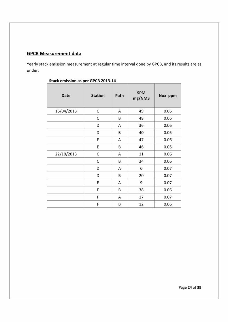
GPCB Measurement data
Yearly stack emission measurement at regular time interval done by GPCB, and its results are as
under.
Stack emission as per GPCB 2013‐14
Date Station Path SPM
mg/NM3 Nox ppm
16/04/2013 C A 49 0.06
C B 48 0.06
D A 36 0.06
D B 40 0.05
E A 47 0.06
E B 46 0.05
22/10/2013 C A 11 0.06
C B 34 0.06
D A 6 0.07
D B 20 0.07
E A 9 0.07
E B 38 0.06
F A 17 0.07
F B 12 0.06
Page 25 of 39
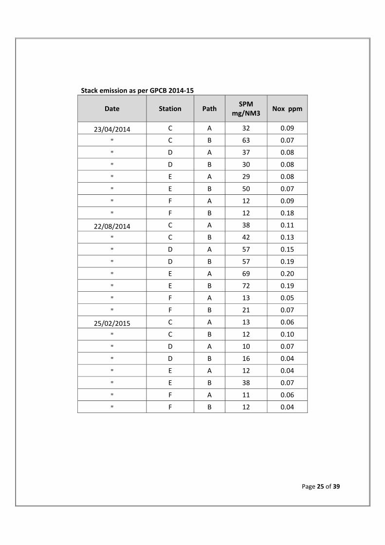
Stack emission as per GPCB 2014‐15
Date Station Path SPM
mg/NM3 Nox ppm
23/04/2014 C A 32 0.09
" C B 63 0.07
" D A 37 0.08
" D B 30 0.08
" E A 29 0.08
" E B 50 0.07
" F A 12 0.09
" F B 12 0.18
22/08/2014 C A 38 0.11
" C B 42 0.13
" D A 57 0.15
" D B 57 0.19
" E A 69 0.20
" E B 72 0.19
" F A 13 0.05
" F B 21 0.07
25/02/2015 C A 13 0.06
" C B 12 0.10
" D A 10 0.07
" D B 16 0.04
" E A 12 0.04
" E B 38 0.07
" F A 11 0.06
" F B 12 0.04

Page 26 of 39
Stack emission as per GPCB 2015‐16
Date Station Path SPM
mg/NM3 Nox ppm
09/04/2015 D A 47 0.10
" E A 59 0.11
" F A 57 0.14
04/08/2015 D B 54 0.90
" E B 35 0.49
" F B 39 1.12
06/11/2015 D A 71 0.08
" E A 71 0.03
" F A 65 0.07
22/03/2016 D B 38 0.67
" E B 55 0.67
" F B 48 0.72
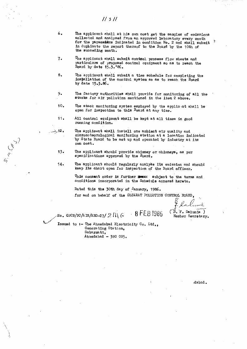
Following documents are reproduce hear for reference.
The copy of Consent to operate is first time issued by GPCB in the year 1986.
The copy of No objection certificate (NOC) for our F unit and C unit as issued by GPCB in
the year 1985 and 1993 respectively is also reproduce hear for ready reference.
The copy of latest Consent to operate issued by GPCB in the year 2013.

830789
Typewritten Text
Page : 27 of 39

830789
Typewritten Text
Page : 28 of 39
830789
Typewritten Text
Page : 29 of 39

830789
Typewritten Text
Page : 30 of 39

830789
Typewritten Text
Page : 31 of 39

830789
Typewritten Text
830789
Typewritten Text
Page : 32 of 39

830789
Typewritten Text
Page : 33 of 39
830789
Typewritten Text
Page : 34 of 39

830789
Typewritten Text
Page : 35 of 39

830789
Typewritten Text
Page : 36 of 39

830789
Typewritten Text
Page : 37 of 39

830789
Typewritten Text
Page : 38 of 39

830789
Typewritten Text
Page : 39 of 39