Properties and failure mechanisms of z-pinned …mams.rmit.edu.au/mp942juyagj41.pdfProperties and...
13
Properties and failure mechanisms of z-pinned laminates in monotonic and cyclic tension P. Chang a , A.P. Mouritz a, * , B.N. Cox b a School of Aerospace, Mechanical and Manufacturing Engineering, RMIT University, GPO Box 2476V, Melbourne, Victoria 3001, Australia b Rockwell Scientific Co LLC, 1049 Camino Dos Rios, Thousand Oaks, CA 91360, USA Received 30 January 2005; received in revised form 3 November 2005; accepted 9 November 2005 Abstract The effects of through-thickness reinforcement of carbon/epoxy laminates with thin pins on the in-plane tensile properties, tensile fati- gue life and failure mechanisms are investigated. Tensile studies in the 0° fibre direction are performed on unidirectional and quasi- isotropic laminates reinforced with different volume contents and sizes of fibrous composite z-pins. Microstructural analysis reveals that z-pinning causes several types of damage, including out-of-plane fibre crimping, in-plane fibre distortion, mild dilution of the in-plane fibre volume fraction due to laminate swelling, and clusters of broken fibres. In unidirectional composites, resin pockets form around pins and coalesce into continuous resin channels at higher z-pin contents. Young’s modulus falls only a few percent at most, due partly to in-plane fibre dilution and partly to fibre waviness. Monotonic tensile strength is degraded more significantly, falling linearly with both pin content and pin diameter. Comparison with prior data shows that the rate of degradation is evidently a strong function of the particular pin insertion method used. Failure mechanisms include fibre rupture, presumably affected by broken fibres, and, in unidirec- tional laminates, longitudinal splitting cracks emanating from resin pockets. Whereas non-pinned laminates show very modest fatigue effects, the pinned laminates exhibit strong fatigue effects, with strength falling by as much as 33% at 10 6 cycles. The slope of the fatigue life (S–N) curve tends to increase in magnitude with pin content and density. Limited evidence and prior literature suggest that the dominant fatigue mechanism may be progressive softening and fibre damage in misaligned segments of in-plane fibres. Ó 2005 Elsevier Ltd. All rights reserved. Keywords: A. Polymer–matrix composites; B. Fatigue; B. Mechanical properties; Z-pins 1. Introduction A long-standing problem with fibre-reinforced polymer laminates is their low delamination resistance and poor impact damage tolerance due to the lack of through-thick- ness reinforcing fibres. This problem has restricted the use of laminated composites in structures prone to impact, in- plane shear or through-thickness tensile loads. New mate- rials and techniques have been developed to increase the delamination toughness and impact resistance of laminates, including toughened resins, fibre treatments, stitching and through-thickness weaving. Another technique that has great potential is z-pinning, which involves inserting thin metal or fibrous composite pins through a laminate to pro- vide through-thickness reinforcement. Various z-pinning methods have been proposed or used since the 1970s for inserting pins oriented through-the-thick- ness of a laminate [1–12]. The early insertion methods were rudimentary, and basically involved the manual pushing of each pin into the composite, which is slow and potentially imprecise. The particular method used in the present study, and perhaps the most widespread for high-performance polymer composite laminates over the last decade, is the pro- cess of pushing pins from a foam bed by pressure and acous- tic vibration into prepreg [8,12]. An advantage of this process is that the insertion process can be semi-automated for wide-area reinforcement of a composite component. Z-pins can increase the in-plane shear strength, inter- laminar fracture toughness and impact damage resistance 1359-835X/$ - see front matter Ó 2005 Elsevier Ltd. All rights reserved. doi:10.1016/j.compositesa.2005.11.013 * Corresponding author. Tel.: +61 3 9925 6269; fax: +61 3 9925 8108. E-mail address: [email protected] (A.P. Mouritz). www.elsevier.com/locate/compositesa Composites: Part A 37 (2006) 1501–1513
Transcript of Properties and failure mechanisms of z-pinned …mams.rmit.edu.au/mp942juyagj41.pdfProperties and...

www.elsevier.com/locate/compositesa
Composites: Part A 37 (2006) 1501–1513
Properties and failure mechanisms of z-pinned laminates inmonotonic and cyclic tension
P. Chang a, A.P. Mouritz a,*, B.N. Cox b
a School of Aerospace, Mechanical and Manufacturing Engineering, RMIT University, GPO Box 2476V, Melbourne, Victoria 3001, Australiab Rockwell Scientific Co LLC, 1049 Camino Dos Rios, Thousand Oaks, CA 91360, USA
Received 30 January 2005; received in revised form 3 November 2005; accepted 9 November 2005
Abstract
The effects of through-thickness reinforcement of carbon/epoxy laminates with thin pins on the in-plane tensile properties, tensile fati-gue life and failure mechanisms are investigated. Tensile studies in the 0� fibre direction are performed on unidirectional and quasi-isotropic laminates reinforced with different volume contents and sizes of fibrous composite z-pins. Microstructural analysis reveals thatz-pinning causes several types of damage, including out-of-plane fibre crimping, in-plane fibre distortion, mild dilution of the in-planefibre volume fraction due to laminate swelling, and clusters of broken fibres. In unidirectional composites, resin pockets form aroundpins and coalesce into continuous resin channels at higher z-pin contents. Young’s modulus falls only a few percent at most, due partlyto in-plane fibre dilution and partly to fibre waviness. Monotonic tensile strength is degraded more significantly, falling linearly with bothpin content and pin diameter. Comparison with prior data shows that the rate of degradation is evidently a strong function of theparticular pin insertion method used. Failure mechanisms include fibre rupture, presumably affected by broken fibres, and, in unidirec-tional laminates, longitudinal splitting cracks emanating from resin pockets. Whereas non-pinned laminates show very modest fatigueeffects, the pinned laminates exhibit strong fatigue effects, with strength falling by as much as 33% at 106 cycles. The slope of the fatiguelife (S–N) curve tends to increase in magnitude with pin content and density. Limited evidence and prior literature suggest that thedominant fatigue mechanism may be progressive softening and fibre damage in misaligned segments of in-plane fibres.� 2005 Elsevier Ltd. All rights reserved.
Keywords: A. Polymer–matrix composites; B. Fatigue; B. Mechanical properties; Z-pins
1. Introduction
A long-standing problem with fibre-reinforced polymerlaminates is their low delamination resistance and poorimpact damage tolerance due to the lack of through-thick-ness reinforcing fibres. This problem has restricted the useof laminated composites in structures prone to impact, in-plane shear or through-thickness tensile loads. New mate-rials and techniques have been developed to increase thedelamination toughness and impact resistance of laminates,including toughened resins, fibre treatments, stitching andthrough-thickness weaving. Another technique that hasgreat potential is z-pinning, which involves inserting thin
1359-835X/$ - see front matter � 2005 Elsevier Ltd. All rights reserved.
doi:10.1016/j.compositesa.2005.11.013
* Corresponding author. Tel.: +61 3 9925 6269; fax: +61 3 9925 8108.E-mail address: [email protected] (A.P. Mouritz).
metal or fibrous composite pins through a laminate to pro-vide through-thickness reinforcement.
Various z-pinning methods have been proposed or usedsince the 1970s for inserting pins oriented through-the-thick-ness of a laminate [1–12]. The early insertion methods wererudimentary, and basically involved the manual pushing ofeach pin into the composite, which is slow and potentiallyimprecise. The particular method used in the present study,and perhaps the most widespread for high-performancepolymer composite laminates over the last decade, is the pro-cess of pushing pins from a foam bed by pressure and acous-tic vibration into prepreg [8,12]. An advantage of thisprocess is that the insertion process can be semi-automatedfor wide-area reinforcement of a composite component.
Z-pins can increase the in-plane shear strength, inter-laminar fracture toughness and impact damage resistance

Fig. 1. Schematic of the z-pin insertion process.
1502 P. Chang et al. / Composites: Part A 37 (2006) 1501–1513
of laminates as well as improve the ultimate failure strengthof composite joints by a crack bridging mechanism[3,8,9,13–17]. For these reasons, z-pinned laminates areused in military aircraft such as the F/A-18 E/F Hornetand in Formula 1 racing cars [18]. However, all methodsof pinning, including insertion by vibration and pressurefrom a foam bed, are associated with deformation of thein-plane fibres, which may lead to degradation of the in-plane properties of the laminate. An important steptowards certifying the safety of structures that contain z-pins must therefore be to develop methods of accountingwith confidence for in-plane property knockdown and itsdependence on defects induced by the pinning process.
In prior studies of in-plane property knockdown,Steeves and Fleck [19] and Stringer and Hiley [15] reportthat the compressive strength of carbon/epoxy laminate isdegraded by local distortion and crimping of the load-bear-ing fibres around the z-pins, which lowers the compressivestrain required to create kink bands that cause failure. Fri-etas et al. [8,9,20], Steeves [21] and Stringer and Hiley [15]found the tensile strength of carbon/epoxy laminate is alsoreduced with z-pinning. The mechanisms responsible forthe loss in tensile strength are not well understood,although it is attributed to a reduction in the fibre volumecontent caused by fibre spreading together with fibre dis-tortion and resin-rich regions around the z-pins. Publisheddata on the tensile properties of z-pinned laminates arescarce [8,9,20,21], and the influence of the microstructuraldamage caused by z-pinning on the strengthening processesand failure mechanisms have not been determined. Fur-thermore, the tensile fatigue properties and cyclic damagemechanics of z-pinned laminates have not been evaluated,despite the potential application of these materials in struc-tural components subject to fatigue loading, such as wingpanels and joints on aircraft.
The aim of this research is to investigate the effect of z-pinning on the in-plane tensile properties, tensile fatigueperformance and failure mechanisms of carbon/epoxy lam-inates. The influence of the volume content and size of thez-pins on the Young’s modulus, tensile strength and fatiguelife in the 0� fibre direction of unidirectional and quasi-isotropic laminates is determined, and changes to theseproperties are related to changes in the microstructureand failure mechanisms caused by z-pinning.
2. Materials and experimental techniques
2.1. Fabricating z-pinned laminates
The laminates were made using a carbon/epoxy(CYCOM 970) prepreg tape supplied by Cytec. The epoxymatrix is a high cure temperature, non-toughened resin.The specimens contained 20 plies of tape stacked in a uni-directional or quasi-isotropic [0/±45/90/±45/0]s pattern.Prior to curing, the laminates were debulked by vacuumbagging and then z-pinned using pultruded carbon/bisma-leimide Z-FibersTM supplied by Aztex Inc. The z-pins were
8 mm long, and their tips were chamfered to an angle of 45�to ease their insertion into the prepreg stack.
The z-pins were inserted in the orthogonal directionthrough the uncured prepreg using a hand-held ultrasoni-cally actuated horn in a process that is shown schematicallyin Fig. 1, and is described in detail by Freitas et al. [9,10].The z-pins as supplied are arranged in a square patternwithin a low-density foam preform. The foam is used toensure an even spacing between the z-pins and to providelateral support to the pins during insertion. The z-pins wereinserted progressively by moving the ultrasonic horn over

Table 1Thickness of the laminates with different types of z-pin reinforcement
Laminate Z-Pin volumecontent (%)
Z-Pindiameter (mm)
Thickness(mm)
Unidirectional 0.0 0 3.94 ± 0.13Unidirectional 0.5 0.28 4.00 ± 0.07Unidirectional 2.0 0.28 4.02 ± 0.07Unidirectional 4.0 0.28 4.07 ± 0.07Unidirectional 2.0 0.51 4.00 ± 0.07Quasi-isotropic 0.0 0 4.00 ± 0.04Quasi-isotropic 0.5 0.28 4.01 ± 0.03Quasi-isotropic 2.0 0.28 3.99 ± 0.06Quasi-isotropic 4.0 0.28 4.10 ± 0.03
P. Chang et al. / Composites: Part A 37 (2006) 1501–1513 1503
the foam bed several times until all the pins had fully pen-etrated the prepreg, which was determined to be when theirleading tip protruded slightly from the underside of theprepreg stack. The z-pins protruded by less than 0.5 mm,and the excess length was carefully abraded away after cur-ing using fine-grade polishing paper without scratching thesurface ply. The z-pins also protruded from the entry sidebecause they were considerably longer than the thicknessof the prepreg stack, which was nominally 4 mm thick.The excess pin length on this side was about 3.5 mm, andthis was removed by first shearing the pins along the lam-inate surface using a sharp blade and then carefully polish-ing away any excess length. A considerable shear forceneeds to be applied to cut the z-pins, and this caused somelateral displacement and deformation of in-plane fibres,which are described later. This process of cutting the z-pinsis commonly practised in the manufacture of z-pinned lam-inates [8–10]. After cutting, two final plies were placed onthe stack to stop dimpling of the surface caused by pro-truding z-pins. This ensured a smooth surface finish. Theaddition of these two plies was included in the final thick-ness of the laminate.
The laminates were reinforced with thin (0.28 mm)diameter z-pins to volume contents of 0.5%, 2.0% and4.0%. These specimens were used to investigate the effectof z-pin content on tensile properties and fatigue perfor-mance. In addition, the unidirectional laminate was rein-forced to a volume content of 2.0% using thin (0.28 mm)or thick (0.51 mm) diameter z-pins to study the effect ofpin size on the mechanical performance.
The entire gauge region of the tensile coupon specimenswas z-pinned, with the z-pins aligned in parallel rows alongthe specimen (see Fig. 2). The spacing between the axialrows of small diameter z-pins was 3.5, 1.75 and 1.2 mmfor the volume contents of 0.5%, 2.0% and 4.0%, respec-tively. The row spacing for the large diameter z-pins was3.2 mm, thus maintaining the volume content of 2.0%.
After z-pinning, the laminates were consolidated andcured in an autoclave at an overpressure of 500 kPaand temperature of 115 �C for 1 h and then 750 kPa and180 �C for 2 h. The average fibre volume fraction of thelaminates was nominally 62%. For reference, unpinned uni-directional and quasi-isotropic laminates were manufac-tured using the same curing process.
85mm 100mm
4mm
z-pin
Fig. 2. Dimensions of th
2.2. Fiber volume fraction and laminate thickness
The laminates were constrained within a picture frameduring z-pinning to suppress lateral spreading of the fibresdue to swelling that can occur due to the displacement ofin-plane fibres. Table 1 gives the thickness of the laminateswith different volume contents and sizes of z-pins. Thenominal thickness of the laminates is 4.0 mm, but the thick-ness varies by a few percent from specimen to specimen.
In the unidirectional laminates, the variation is corre-lated with the volume displaced by the pins: the thicknessrises by a fraction that is approximately the same as thepin volume fraction. Thus the volume fraction of the in-plane fibres in the total laminate volume less the volumeof the pins is approximately conserved. However, asdetailed in Section 3, inserting pins into the unidirectionallaminates also creates significant resin pockets next to eachpin along the fibre direction. Since the pockets representsfurther volume from which fibres have been displaced, ofmagnitude roughly twice that occupied by the pins them-selves (see below), it follows that fibre compaction mustalso occur in some zones within the laminate. Indeed, fibredisplacement is accommodated approximately one-third bythickness increase and approximately two-thirds by fibrecompaction. The spatial distribution of the fibre compac-tion is not easily determined.
In the quasi-isotropic laminates, the thickness rises by afraction that is approximately the same as the pin volumefraction only for the laminate with the highest content ofpins. The other laminates have unchanged thickness,within experimental uncertainty. Part of the difference with
85mm
25mm
ning
10mm
e tensile specimens.

0 5 10 15 20 25 30 350
5
10
15
20
25 0.28 mm Z-pins
Pro
port
ion
of Z
-Pin
s (%
)
Z-Pin Offset Angle (degrees)(a)
1504 P. Chang et al. / Composites: Part A 37 (2006) 1501–1513
unidirectional laminates could be that resin pockets aremuch smaller in the quasi-isotropic laminates (see below),so that fibres are displaced from a lesser volume, not muchgreater than the volume of the pins themselves. For thelower pin densities in the quasi-isotropic laminates, mostof the fibre displacement is evidently accommodated byfibre compaction alone.
2.3. Monotonic and fatigue tensile testing
Monotonic and fatigue tensile tests were performed inthe 0� fibre direction on the laminates using rectangular cou-pons with the dimensions given in Fig. 2. The monotonictests were performed using a 250 kN MTS machine at aloading rate of 1 mm/min. The fatigue tests were performedusing the same MTS machine operated under a cyclic loadsinusoidal waveform with a stress (R) ratio of 0.6 and load-ing frequency of 5 Hz. The materials were tested to a rangeof peak fatigue stress levels between 70% and 95% of themonotonic failure strength to generate fatigue life (S–logN)curves. The minimum peak fatigue stress of 70% was usedbecause this is about the fatigue limit of the laminate, andtesting at lower stress levels failed to caused fatigue-inducedfracture. The number of load cycles to failure (N) was takento be when the laminate could no longer carry the peak fati-gue stress, and this coincided with complete fracture of thespecimen. Fatigue tests performed on specimens that didnot fail were stopped at one million load cycles.
3. Results and discussion
3.1. Microstructural characterisation
Microstructural changes to the fibre architecture ofcomposites caused by the insertion of z-pins are knownto alter the mechanical properties [8–10,19,21]. Therefore,the microstructure of the unidirectional laminate wasexamined to aid in understanding the effect of z-pinningon the mechanical properties and failure mechanisms.Fig. 3 shows a cross-section view of a z-pin in the laminate,
Fig. 3. Cross-section view of a z-pin in the unidirectional laminate. Notethat the pin is inclined at an angle (/) from the orthogonal direction.
and the pin is seen to be inclined at an angle (/) from theorthogonal (through-thickness) direction. Microstructuralanalysis revealed that / was statistically distributed, asshown by the histograms and fitted Gaussian density func-tions of Fig. 4. The median angles for the small and largediameter pins were 14� and 23�, respectively.
The cause of the offset was investigated by measuringthe distribution of / at different stages in the manufactureof the z-pinned unidirectional laminates, viz. (i) in the as-received condition in the foam preform, (ii) after z-pinshad been inserted about half-way through the laminate,(iii) after z-pins had been inserted completely through thelaminate, (iv) after removal of the excess pin lengths fromboth surfaces, and (v) in the laminate after consolidationand curing in the autoclave. The median offset angles forthe two pin sizes after these manufacturing stages are givenin Fig. 5. The small z-pins are not offset significantly fromthe original (as-received) condition during insertion. Theoffset angle of the small z-pins increased suddenly whentheir excess length was removed by shear cutting andabrading. The direction of the rotation is that in whichthe shear force was applied. In the case of large diameter
0 5 10 15 20 25 30 350
5
10
15
20
25 0.51 mm Z-pins
Pro
port
ion
of Z
-Pin
s (%
)
Z-Pin Offset Angle (degrees)(b)
Fig. 4. Median offset angles for the (a) small and (b) large z-pins duringthe different manufacturing stages of the z-pinned laminates.

0 5 10 15 20 25
Small Diameter Z-Pins
Man
ufac
turin
g S
tage
Cured Laminate
Shear Cutting
Fully Inserted
Inserted Half-Way
As-Recieved
Median Z-Pin Offset Angle (degrees)(a)
0 5 10 15 20 25
Large Diameter Z-Pins
Man
ufac
turin
g S
tage
Cured Laminate
Shear Cutting
Fully Inserted
Inserted Half-Way
As-Recieved
Median Z-Pin Offset Angle (degrees)(b)
Fig. 5. Schematic of the offset to the z-pins caused by shear cutting.
Fig. 6. Photograph of in-plane fibre distortion and resin-rich pocketsaround a z-pin in a undirectional laminate.
P. Chang et al. / Composites: Part A 37 (2006) 1501–1513 1505
pins, shear cutting caused a relatively small increase in /,with the largest increase caused when the laminates areconsolidated under pressure in the autoclave.
Fig. 3 also shows crimping of carbon fibres around a z-pin near the mid-plane of the laminate. The crimping wassevere, with the fibres being misaligned by as much as60–70� from their original direction. However the damagewas confined to a small region close to the z-pin (within0.3 mm). It is seen in Fig. 3 that the crimping was not sym-metric around the pin, but was more severe on the sideinclined to an angle under 90�. This indicates that crimpingis caused by a combination of the force on the pins duringinsertion and the rotation of the pin when they becomemisaligned. Thin elongated voids were present inside someof the z-pins, including the pin shown in Fig. 3. These voidswere created during the manufacture of the z-pins, presum-ably because the matrix resin could not infiltrate regions ofhigh fibre content.
It is possible that some of the carbon fibres were brokenduring the z-pinning process. The pin tip was chamfered toassist their insertion through the laminate by spreading thefibres. However, it is possible that some fibres could not bespread sufficiently to avoid being crushed under the pin tip.The proportion of the fibres that may have been fracturedby the z-pins could not be accurately measured, although itis expected that the broken fibres occur in clusters close to
the pins. There was clearly far less damage to fibres thandepicted in prior work by Steeves and Fleck [19], whichis attributed to the superior insertion technique used in thisstudy. However, anecdotal evidence has made clear thatresults in this method of pin insertion, viz. by pressureand vibration from a foam base, depend on the tool usedand operator skill.
Fig. 6 shows an in-plane view of a z-pin in the unidirec-tional laminate, and it is seen that the carbon fibres havebeen spread to accommodate the pin. This causes distor-tion of the fibres and the formation of resin-rich pocketswhere the fibres have been displaced. The fibre distortionangle (h) was measured from photomicrographs to be4.0 ± 0.5� for the small diameter pins and 5.4 ± 0.8� forthe large pins. The fibres within a small volume of materialsurrounding each z-pin were displaced in the axial (x-) andtransverse (y-) directions, as shown schematically in Fig. 7.The dimensions of the affected area were measured fromphotomicrographs of specimens containing a single z-pin,and it is seen the fibres were distorted in both directionsover a distance of �1.0 mm for the small pin size and1.5 mm for the large pin.
While the fibres surrounding each z-pin in the unidirec-tional laminate were only distorted over a small region,when the pins were spaced closely together the resin-richregions join together to form continuous resin channelsalong the axial rows of z-pins, as shown in Fig. 8. It is seenin Fig. 6 that the length of the resin-rich region along thefibre direction in the laminate reinforced with the smallpins is �2 mm. When the spacing between the z-pins is lessthan this length, neighbouring resin-rich regions jointogether to form a continuous resin channel. The resinchannels did not occur in the laminate with a z-pin contentof 0.5% because the pins were spaced 3.5 mm apart. How-ever, resin channels occurred in the unidirectional lami-nates with z-pin contents of 2.0% and 4.0% because thepins were spaced less than 2 mm apart. In some cases, smallvoids formed in the resin channels because the epoxy resingelled during curing before it had filled the cavity createdby the displacement of the fibres. The 0� plies in the

(a)
(b) 2.8mm
1.5mm2θ = 10.8° ± 1.5 Z-Pin Resin Zone
0.8mm
2.0mm
2θ= 8o ± 1
Z-Pin
Resin Zone
Fig. 7. Schematic illustrations showing the dimensions of the disturbedregion surrounding the (a) small and (b) large diameter z-pins in theunidirectional laminate.
Fig. 8. Photograph of a resin-rich channel along a row of z-pins in theunidirectional laminate.
25
50
75
100
125
150
00
Line-of-best-fit (nominal specimen thickness)
Line-of-best-fit (actual specimen thickness)
Quasi-istropic laminate
Unidirectional laminate
You
ng's
Mod
ulus
(G
Pa)
Z-Pin Volume Content (%)(a)
0.0 0.1 0.2 0.3 0.4 0.50
25
50
75
100
125
150
Line-of-best-fit (nominal specimen thickness)
Line-of-best-fit (actual specimen thickness)
You
ng's
Mod
ulus
(G
Pa)
Z-Pin Diameter (mm)(b)
1 2 3 4
Fig. 9. Effect of (a) volume content and (b) size of z-pins on the Young’smodulus of the laminates. The closed and open data points represent themodulus values calculated using the actual laminate thickness and anominal thickness of 4 mm, respectively.
1506 P. Chang et al. / Composites: Part A 37 (2006) 1501–1513
quasi-isotropic laminates also developed continuous resinchannels when the z-pin content was 2% and 4%. The±45� plies also develop resin rich channels in these direc-tions and resin channels formed along the transverse direc-tion in the 90� plies.
3.2. Monotonic tension
3.2.1. Summary of trends
The modulus and strength under tension were deter-mined by dividing the measured load in an experiment bythe product of the measured width of the specimen andeither (1) the actual specimen thickness or (2) a fixed, nom-inal thickness (4.0 mm). Since, during pinning, the ply fab-rics were constrained from lateral (in-plane) spreading by
fences, the density of fibres per unit width is expected toremain very close in the pinned laminates to its value inunpinned laminates. On the other hand, small variationsin thickness arise from specimen to specimen. Since theload in the tests is carried almost entirely by the fibres(which are two orders of magnitude stiffer and strongerthan the matrix), variations in specimen thickness for fixeddensity of fibres per unit width will lead to changes in mod-ulus or strength simply by fibre dilution. Comparison ofstiffness or strength calculated assuming fixed thicknesswith values found using actual thickness will reflectchanges due to other factors.
The effect of increasing either the z-pin content or the pinsize on the longitudinal Young’s modulus of the unidirec-tional and quasi-isotropic laminates is shown in Fig. 9.The closed and open data points represent the modulus val-ues calculated using the actual specimen thickness and anominal thickness of 4 mm, respectively. The solid and

0 30
500
1000
1500
2000
Quasi-isotropic laminate
Unidirectional laminate
Ten
sile
Str
engt
h (M
Pa)
Z-Pin Volume Content (%)(a)
0.0 0.1 0.2 0.3 0.4 0.50
500
1000
1500
2000
Ten
sile
Str
engt
h (M
Pa)
Z-Pin Diameter (mm)(b)
41 2
Fig. 10. Effect of (a) volume content and (b) size of z-pins on the tensilestrength of the laminates. The closed and open data points represent themodulus values calculated using the actual laminate thickness and anominal thickness of 4 mm, respectively. The lines show the reduction instrength calculated using Eq. (1).
P. Chang et al. / Composites: Part A 37 (2006) 1501–1513 1507
dashed lines show linear regressions for these two datatypes, fitted under the constraint that they have the samevalue at zero pin content. The modulus values for both uni-directional and quasi-isotropic laminates show scatteramong different pin diameters and volume fractions thatis comparable to overall trends. Therefore, fitted lines havemodest correlation factors. The trends in data for the unidi-rectional laminates are that (1) the modulus decreasesapproximately 1.5% for each 1% of z-pin volume contentfor pins of diameter 0.28 mm when computed using a con-stant specimen thickness, but remains almost independentof pin content when computed using the actual specimenthickness; and (2) the modulus decreases approximately5.0% for each 1% of pin volume content for pins of diameter0.51 mm, with only weak dependence on which specimenthickness is used. For the quasi-isotropic laminates, thereis no statistically significant change in the modulus withincreasing content, whichever specimen thickness is used.
The fitted trend lines suggest that the greater part ofchanges in the modulus with pin content for both laminatetypes reinforced by 0.28 mm pins are due to laminate swell-ing; the modulus decrease is not significantly different fromzero when a constant specimen thickness value is used incalculations. For the larger diameter pins, the decline inmodulus is much greater and significantly exceeds thedecline attributable to swelling. For the larger pins, thegreater part of the modulus decline is attributed to fibremisalignment. However, it is not know what contributionthe offset of the pins had on the loss in modulus. Figs. 3,6 and 7 suggest that, at most pin densities, fibre misalign-ment, both in-plane and out-of-plane, is localized aroundeach pin and extends over a volume that is a small multipleof the pin volume, approximately 3–4. Assuming that themisalignment (which is quite severe in the out-of-planedirection—Fig. 3) reduces the effective modulus of theaffected material by a factor of 2 or so, one comes, to orderof magnitude, to reductions of 1–2% per 1% of pin content.This is in the range that could explain the measured mod-ulus changes for the larger diameter pins. That this effectshould be significant for the larger pins and not the smallerpins could be attributed to a greater proportion of mis-alignment damage.
The effect of z-pinning on tensile strength is shown inFig. 10. The closed and open data points present thestrength values calculated using actual and constant thick-ness values. The strength of the unidirectional laminatedecreased rapidly with both increasing pin volume contentand pin diameter. The reduction ranges, for the casestested, up to approximately 25%. The trends are approxi-mately linear and may be summarised by the followingempirical expression for the ratio of the tensile strength,rt, to that of unpinned laminate, rð0Þt :
rt
rð0Þt
¼ ½1� aDcr� ð1Þ
where cr is the area fraction of the pins and D is their diam-eter. For the unidirectional laminates, a = 14 mm�1. This
fit is shown in Fig. 10 for the unidirectional laminate data.Since thickness variations are much smaller than strengthvariations, no significant change in a results from usingfixed (4 mm) rather than actual specimen thickness in com-puting strengths. The model does not consider the effect ofthe continuous resin channels on the failure strength de-spite the channels causing splitting cracks in the laminatespinned at the intermediate and high densities.
For the quasi-isotropic laminate, the reduction with pinvolume fraction is much smaller, not exceeding approxi-mately 7% for the range of pin densities studied. But a lin-ear trend with even this mild slope has relatively lowcorrelation factor, because the trend is not far from thevariance in the data. Freitas et al. [8,9,20], Steeves [21]and Stringer and Hiley [15] have reported higher reductionsof tensile strength for multiaxial carbon/epoxy laminatesdue to z-pinning. At least in the work of Steeves, this could

1508 P. Chang et al. / Composites: Part A 37 (2006) 1501–1513
be attributed to inferior methods of pin insertion leading toa greater degree of in-plane fibre damage. The other paperscontain insufficient reporting of in-plane fibre deformationto address the question.
If one assumes that the strength of the quasi-isotropiclaminates would also decrease linearly with pin diameter(this was not tested here), then the strength summary ofEq. (1) would again hold approximately. The data ofFig. 10 imply a � 4 mm�1. The curve for the quasi-isotro-pic laminate in Fig. 10 shows Eq. (1) for this value of a.
The only other tensile strength data available to checkthe trend of Eq. (1) are those of Frietas et al. [8], whichare for a cross-ply carbon/epoxy laminate reinforced withz-pins up to a volume content of 10%. The change in lam-inate thickness with increasing z-pin content was notreported, although substantial swelling or in-plane fibredilution must be expected at 10% pin content. The authorsleave unclear whether the swelling effect was consideredwhen calculating the failure stress. Fig. 11 shows the dataof Freitas et al. [8]. Once again, tensile strength falls line-arly with pin content. The closed data points show thestrength values as reported by Freitas et al. If it is assumedthat these data were calculated using a constant specimenthickness and that the actual thickness increased in propor-tion to the pin content (e.g., 5% z-pins caused the laminateto swell by 5%), then the strength values that would befound using the actual specimen thickness can be esti-mated. These are shown by the open data points inFig. 11. The lines in Fig. 11 were calculated using Eq. (1)fitted with the constraint that for constant and adjustedspecimen thickness they should have the same value at zeropin content. The linear fits are a reasonable representationof the data, but the slopes are much higher than for thequasi-isotropic laminates tested in the present work. Forconstant thickness values, the slope a = 25 mm�1; whilefor adjusted thickness values, a = 29 mm�1 (compare with
0 100
100
200
300
400
500
600
700
Ten
sile
Str
engt
h (M
Pa)
Z-Pin Content (%)
Measured strengthCorrected strength
2 4 6 8
Fig. 11. Comparison of measured and calculated tensile strengths for acarbon/epoxy laminate. Measured data from Frietas et al. [9].
a = 4 mm�1 in the present work). For reasons that are notwell understood, the pinning process used by Freitas et al.has apparently caused far more severe damage to thelaminate.
The failure strain for the unidirectional and quasi-iso-tropic laminates decreased at a linear rate with increasingpin content. The stress–strain curves for the unpinnedand pinned laminates were linear, and therefore any lossin elastic modulus and strength caused by pinning resultedin a corresponding reduction in the failure strain. Thereduction in failure strain due to pinning was more signif-icant with the unidirectional laminate because its modulusand, in particular, strength were degraded more by the pinsthan the quasi-isotropic laminate.
3.2.2. Mechanisms of failure
Photographs of failed unidirectional tensile test speci-mens with and without z-pins are presented in Fig. 12.The unidirectional laminate without z-pins failed by liga-ment rupture whereas the failure mode changed with z-pin-ning to a combination of ligament rupture and multiplelongitudinal splitting in the axial direction along the rowsof z-pins. Since failure of the z-pinned specimens was cata-strophic, it is not known whether fibre rupture or splittingoccurred first; the two mechanisms may well interactdynamically during the failure process. Microstructuralexamination of the failed specimens revealed the presenceof small cracks within the resin-rich zones adjoining thez-pins, as shown in Fig. 13. These cracks were not detectedin the specimens prior to tensile testing, which indicatesthat were not caused by thermal effects during curing. Veryfew of these cracks were detected in the failed specimens,although those that were found were aligned in the loaddirection. It is believed the cracks were initiated underthe action of a local transverse tensile strain generated asthe misaligned fibres around a z-pin experience a smalldegree of straightening under axial tensile loading, asdepicted schematically in Fig. 14. Close to the failure stress,these cracks may propagate unstably along the continuousresin-rich channels and trigger the long splitting cracksobserved in Fig. 12.
Fig. 12. Failed tensile specimens of the unidirectional laminate (a) withoutz-pins and (b) with z-pins tested under monotonic loading.
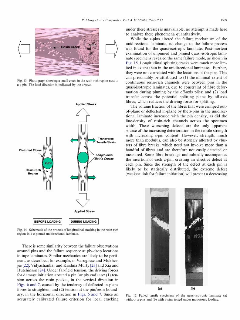
Fig. 13. Photograph showing a small crack in the resin-rich region next toa z-pin. The load direction is indicated by the arrows.
Applied Stress
Longitudinal Matrix Cracks
Transverse Tensile Strain
Resin-Rich Region
Distorted Fibres
Z-Pin
Applied Stress
DURING LOADINGBEFORE LOADING
Fig. 14. Schematic of the process of longitudinal cracking in the resin-richregion in a z-pinned unidirectional laminate.
Fig. 15. Failed tensile specimens of the quasi-isotropic laminate (a)without z-pins and (b) with z-pins tested under monotonic loading.
P. Chang et al. / Composites: Part A 37 (2006) 1501–1513 1509
There is some similarity between the failure observationsaround pins and the failure sequence at ply-drop locationsin tape laminates. Similar mechanics are likely to be perti-nent, as described, for example, in Varughese and Mukher-jee [22], Vidyashankar and Krishna Murty [23] and Xia andHutchinson [24]. Under far-field tension, the driving forcesfor damage initiation around a pin (or ply end) are: (1) ten-sion across the resin pocket, in the vertical direction inFigs. 6 and 7, caused by the tendency of deflected in-planefibres to straighten; and (2) tension at the pin/resin bound-ary, in the horizontal direction in Figs. 6 and 7. Since anaccurately calibrated failure criterion for local cracking
under these stresses is unavailable, no attempt is made hereto analyze these phenomena quantitatively.
While the z-pins altered the failure mechanism of theunidirectional laminate, no change to the failure processwas found for the quasi-isotropic laminate. Post-mortemexamination of unpinned and pinned quasi-isotropic lami-nate specimens revealed the same failure mode, as shown inFig. 15. Longitudinal splitting cracks were much more lim-ited in extent than in the unidirectional laminates. Further,they were not correlated with the locations of the pins. Thiscan presumably be attributed to (1) the minimal extent ofcontinuous resin-rich channels were between pins in thequasi-isotropic laminates, due to constraint of fibre defor-mation during pinning by the off-axis plies; and (2) loadtransfer across the potential splitting plane by off-axisfibres, which reduces the driving force for splitting.
The volume fraction of the fibres that were crimped out-of-plane or deflected in-plane by the z-pins in the unidirec-tional laminate increased with the pin density, as did theline-density of resin-rich channels across the specimenwidth. These worsening defects are the only apparentsource of the increasing deterioration in the tensile strengthwith increasing z-pin content. However, strength, muchmore than modulus, can also be strongly affected by clus-ters of fibre breaks, which need not involve more than ahandful of fibres and are therefore not easily detected ormeasured. Some fibre breakage undoubtedly accompaniesthe insertion of each z-pin, creating an effective defect ateach pin. Since the strength of the defect at each pin islikely to be statiscally distributed, the extreme defect(weakest link for failure initiation) will present a decreasing

0 1 2 3 4 5 61000
1100
1200
1300
1400
1500
1600
1700
1800
Ten
sile
Str
engt
h(M
Pa)
Z-Pin Diameter (mm)
Fig. 17. Effect of single pin diameter on the tensile strength of theunidirectional laminate.
1510 P. Chang et al. / Composites: Part A 37 (2006) 1501–1513
strength as the pin density (and therefore the sample size)rises.
Since in-plane fibre deformation is similar in the anglesof deflection for different z-pin sizes (Fig. 7), perhaps thereduction in strength with increasing z-pin diameter atfixed pin density is related to increased fibre breakage ateach pin insertion. A second possibility is a size effect inthe strength of the resin pockets formed at each pin: whilethe fibre deformation is geometrically similar for differentpin diameters (Fig. 7), the length of the resin pocket scaleswith the pin diameter. Crack initiation in resin pockets isknown to exhibit gauge effects for pockets that are�1 mm in size or less, which is within the size range inthe z-pinned specimens [16,22,23].
The lower fractional loss of strength with rising z-pindensity in the quasi-isotropic laminates compared to theunidirectional laminates (a � 4 vs. a = 14) is presumablyrelated to fewer defects being created in the quasi-isotropiclaminates. Off-axis plies constrain in-plane fibre deforma-tion, and the extent and width of resin-rich channels; andmay possibly, by reducing fibre deflections, also reducefibre breakage.
Some of the z-pins themselves were fractured during ten-sile testing in both the unidirectional and quasi-isotropiclaminates. Fig. 16 shows a cross-section of a broken z-pinwith a crack aligned normal to the tensile load direction.Cracks such as these are believed to initiate at microscopicvoids within the z-pins. However, the cracks do not linkwith the strength controlling failure events (splitting orrupture) and are therefore probably unimportant.
3.2.3. Tests using specimens with a single pin
The effect of z-pin diameter on the tensile strength wasinvestigated further by inserting single rods of differentsizes into unidirectional laminate specimens. The rods wereembedded by hand into the center of the gauge area, ratherthan using the ultrasonic horn. The rods were off-set fromthe orthogonal direction by an angle less than 20�, which issimilar to the range of offset angles when pins were insertedusing the ultrasonic horn. Fibrous z-pins with diameters0.28 and 0.51 mm were supplemented by larger steel pins,with diameters between 0.96 and 5.72 mm. The amountof swelling in the region surrounding the steel rods
Fig. 16. Photograph showing transverse fracture of a z-pin under tensileloading. The load direction is indicated by the arrows.
increased with their diameter. The swelling was greatestat the site of the rod and extended several millimeters away.Since it was not uniform, thickness variation was not con-sidered in calculating the tensile strength. The laminatestrength was found to drop rapidly with increasing pindiameter (Fig. 17), but not linearly. The linear summaryrelation of Eq. (1) should therefore not be used beyondthe maximum pin diameter, 0.5 mm, of the pins for whichthe data it represents were obtained.
3.3. Fatigue properties
Tensile fatigue life (S–logN) curves are presented inFig. 18 for the unidirectional and quasi-isotropic laminatesreinforced with different densities of z-pins. Like most poly-mer composites, the unpinned unidirectional and quasi-iso-tropic laminates show very modest fatigue effects: only 8%and 13% loss of strength over 106 cycles, respectively.Despite the limited amount of data, it is apparent thatmuch stronger fatigue effects arise in the pinned laminates.While the fatigue resistance of the unidirectional laminatewas affected only slightly by the lowest volume content ofz-pins (0.5%), a large reduction occurred at the higher z-pin contents (33% loss of strength over 106 cycles). Thefatigue resistance of the quasi-isotropic laminate also dete-riorated with increasing z-pin content, although the reduc-tion was less severe than for the unidirectional laminate(25% loss of strength over 106 cycles for 4% pin density).The effect of increasing z-pin size on the S–N curve forthe unidirectional laminate is shown in Fig. 19. A similarfractional loss of strength is found for both pin sizes, withthe larger pins leading to lower absolute strengths at allcycle counts.
Fig. 20 shows the gradient of the S–logN curves, m,plotted against the volume content of the z-pins, for fixedpin diameter (0.28 mm). While the data show significantscatter, especially for the quasi-isotropic laminates, there

100 101 102 103 104 105 1060
500
1000
1500
2000
Unidirectional laminate
0% z-pins (m = -23.7 ± 13.2) 0.5% z-pins (m = -37.2 ± 8.1) 2.0% z-pins (m = -84.0 ± 7.5)4.0% z-pins (m = -91.0 ± 12.5)
Ten
sile
Fat
igue
Str
ess
(MP
a)
Cycles to Failure(a)
100 101 102 103 104 105 1060
200
400
600
800 Quasi-isotropic laminate
0% z-pins (m = -15.7 ± 3.9) 0.5% z-pins (m = -10.3 ± 2.9) 2.0% z-pins (m = -25.7 ± 4.1) 4.0% z-pins (m = -25.9 ± 2.7)
Ten
sile
Fa
tigue
Str
ess
(MP
a)
Cycles to Failure(b)
Fig. 18. Effect of volume content of z-pins on the S–N curves for the (a)unidirectional and (b) quasi-isotropic laminates.
40 1 2 3-120
-100
-80
-60
-40
-20
0
Quasi-isotropic Laminate
Unidirectional Laminate
Slo
pe o
f S-N
Cur
ve,
m
Z-Pin Volume Content (%)
Fig. 20. Plot of the slope of the S–N curve against the z-pin content.
P. Chang et al. / Composites: Part A 37 (2006) 1501–1513 1511
is a trend for fatigue effects to increase with pin density upto approximately 2%, beyond which levelling in m suggeststhat they have saturated. The increase of m with density is
100 101 102 103 104 105 1060
500
1000
1500
2000Unidirectional laminate
No z-pins (m = -23.7 ± 13.2) Small z-pins (m = -84.0 ± 7.5)
Large z-pins (m = -77.4 ± 13.5)Ten
sile
Fat
igue
Str
ess
(MP
a)
Cycles to Failure
Fig. 19. Effect of z-pin size on the S–N curve for the unidirectionallaminate.
less for the quasi-isotropic laminates, implying weaker fati-gue effects due to pinning than in the unidirectional lami-nates when measured in terms of absolute strength; butthe difference is less if one considers instead the fractionalloss of strength with cycles.
Post-mortem examination revealed the same failuremodes as in the static tensile samples (see Figs. 12 and15). That is, the unidirectional composite without z-pinsfailed in fatigue by ligament rupture, whereas the z-pinnedunidirectional laminates experienced ligament rupture andlongitudinal splitting along the axial rows of z-pins; whilethe quasi-isotropic laminates always failed by fibre ruptureacross an inclined band. Nevertheless, the significant slopesof the S–N curves imply that substantial cyclic damagemust in fact occur that is not present under monotonicloading. The most likely mechanism is damage in regionsaround pins where fibres have been misaligned. Prior workon tape and textile polymer composites has put forwardtwo possible mechanisms: the attrition of fibres wheremicrofracture of the fibre–matrix interface has permittedrelative sliding between the fibres and the matrix [25];and softening and damage of the resin itself under localcyclic shear, for which evidence has been most compellingin studies of compression fatigue [26,27]. Under nominallyaligned loading, both of these mechanisms act where fibresare misaligned, i.e., where significant local shear stressesarise in coordinates that are aligned with the local fibredirection. The result of progression of fibre damage wouldbe a progressive loss of fibre strength. Progressive matrixdamage can initiate delamination or splitting cracks; and,since it allows straightening of the misaligned fibres, itcan also promote the initiation of cracks in resin pockets(the mechanism illustrated in Fig. 14).
No certain conclusions are possible about how varia-tions in these mechanisms might account for the trends infatigue effects (i.e., in the slope m of the S � log N curves)with pin density. Nevertheless, the fact that fatigue effectsare weak in the absence of pins and strong in their presence

1512 P. Chang et al. / Composites: Part A 37 (2006) 1501–1513
points very strongly to the presence of fatigue mechanismsin the misaligned fibres, as described. Further, one mightspeculate that the apparent saturation at a density ofapproximately 2% in the unidirectional laminates is associ-ated with the extension of resin channels from one pin tothe next, which also occurs for all pin densities above2%. This would suggest that the strength determiningmechanism for the unidirectional laminates is cracking ofthe resin pockets (Fig. 13); and that the principal fatigueeffect is propitiation of this by the progressive softeningof resin allowing fibre straightening. But the evidence forthis sequence is very incomplete.
4. Conclusions
The process of pin insertion caused out-of-plane crimp-ing, in-plane distortion and fracture of fibres near the z-pins. Crimping and distortion of fibres were exacerbatedby pin rotation when excess pin length was sheared offand during laminate consolidation and cure. In unidirec-tional laminates, resin-rich regions formed adjacent to thepins and extending in the fibre direction; and the laminateswelled in the thickness direction, diluting the in-plane fibrevolume fraction. Resin pocket formation and swelling wereminimal in the quasi-isotropic laminates.
The Young’s modulus of laminates reinforced with0.28 mm pins fell with increasing pin density to a degreethat was consistent with the degree of swelling, i.e., slightlyin the unidirectional laminates and not significantly in thequasi-isotropic laminates. The modulus fell at a greaterrate for 0.51 mm pins (unidirectional laminates only), sug-gesting that, for these pins, it was affected significantly byfibre distortion, which is assumed to rise with pin diameter.
The tensile strength was degraded more than Young’smodulus by z-pinning. The strength decreased approxi-mately linearly with increasing pin density and size andat a far greater rate in the unidirectional laminates thanin the quasi-isotropic laminates. Key mechanisms arebelieved to be clusters of broken fibres near the z-pins, aug-mented in the unidirectional laminates by cracking in theresin pockets, where fibre straightening initiates tensile rup-ture and longitudinal splitting. Both the strength of flawsassociated with fibre breaks and the propensity for resinpocket cracking could reasonably be expected to increasewith pin density and diameter, accounting for the observedtrends. The more modest strength loss in the quasi-isotro-pic laminates is attributed tentatively to the constraint ofoff-axis fibres, which can suppress longitudinal splittingcracks and perhaps minimizes breakage damage to fibres.
The tensile fatigue lives of the unidirectional laminatesand, to a lesser extent, the quasi-isotropic laminates werealso reduced substantially by z-pinning. Softening and dam-age of misaligned fibre regions may be the primary fatiguemechanism, but this has not been clearly established.
Comparison with other data in the literature revealsorder-of-magnitude variability in the rate of damage withincreasing pin density, which must presumably be attrib-
uted to differences in the details of the pin insertion pro-cess, via unknown mechanisms. Such variability maypose a significant barrier to more widespread use of pin-ning technology.
Trends in the rate of degradation of modulus andstrength with pin diameter, at fixed pin area fraction, sug-gest that using finer pins than those used here might avoidsignificant degradation of in-plane properties under mono-tonic loading altogether. A goal of pin diameters less thanapproximately 0.1 mm would seem reasonable for this,based on the present data. However, it is not as clear thatloss of strength in cyclic loading would be as easilyavoided, because the fractional loss of fatigue strength to106 cycles is similar for both diameter pins studied.
Microstructural and geometric details such as specimenthickness should be regarded as critical elements of datareporting, since variations in fibre density can vary withprocessing and can easily be comparable to the knock-downs in modulus and even strength that can occur withz-pinning.
Acknowledgements
This research was performed with financial support pro-vided by the Australian Research Council (Grant No.DP0211709). PC thanks the CRC for Advanced CompositeStructures Ltd. for the provision of a top-up scholarship.BNC was supported by the US Department of Energy,Grant No. DE-FG03-97ER45667. Funding by the USDepartment of Energy does not constitute an endorsementof the views expressed in this paper.
References
[1] Darbyshire HF. Report, Report No.: BDX-613-144. Bendix Aero-space-Electronics Company, 1970.
[2] Bradshaw FJ, Dorey G, Sidey GR. Impact resistance of carbon fibrereinforced plastics. Technical Report, Report No.: 72240. RoyalAircraft Establishment, Farnborough, 1973.
[3] Huang SL, Richey RJ, Deska EW. Cross reinforcement in a GR/EPlaminates. In: Proceedings of the American society of mechanicalengineers, Annual winter meeting, 10–15 December 1978.
[4] Krasnov VI, Kuznetsov VA, Yu A. Automated method of transversereinforcement of composites by short fibres. Mekh KompozitnykhMater 1987;3:449–504.
[5] Murrin LJ, Erbacher H. Composite center fuselage—Phase I. In:Proceedings of the 35th annual conference on reinforced plastics andcomposites, 1980.
[6] Tomashevskii VT, Romanov DA, Shalygin VN, Panfilov NA. Effectof radial reinforcement on the strength of fibreglass shells subjected toloading by external pressure. Mekh Kompozitnykh Mater1980;2:205–10.
[7] Tomashevskii VT, Shalygin VN, Romanov DA, Sitnikov SY.Transversal reinforcement of composite materials using ultrasonicvibrations. Mekh Kompozitnykh Mater 1987;6:1068–71.
[8] Freitas G, Magee C, Dardzinski P, Fusco T. Fiber insertion processfor improved damage tolerance in aircraft laminates. J Adv Mater1994;25:36–43.
[9] Freitas G, Fusco T, Campbell T, Harris J, Rosenberg S. Z-fibretechnology and products for enhancing composite design. In:Proceedings of the 83rd meeting of the AGARD SMP conference

P. Chang et al. / Composites: Part A 37 (2006) 1501–1513 1513
on bolted/bonded joints in polymeric composites, Florence Italy,Paper 17, 2–3 September 1996.
[10] Partridge IK, Cartie DDR, Bonnington T. Manufacture and pefor-mance of z-pinned composites. In: Shonaike G, Advani S, editors.Advanced polymeric composites. Florida: CRC Press; 2003.
[11] Tong L, Mouritz AP, Bannister MK. 3D fibre reinforced polymercomposites. London: Elsevier; 2002.
[12] Boyce JS, Fritas GA, Magee CL, Fusco TM, Harris JJ, Kunkle E.Ultrasonic fastening system and method, Patent WO 98/29243, 9 July1998.
[13] Rugg KL, Cox BN, Ward KE, Sherrick GO. Damage mechanismsfor angled through-thickness rod reinforcement in carbon–epoxylaminates. Composites 1998;29A:1603–13.
[14] Cartie DDR, Partridge IK. Delamination behaviour of z-pinnedlaminates. In: Proceedings of the 12th international conference oncomposite materials, Paris, 5–9 July 1999.
[15] Stringer LG, Hiley MJ. Through-thickness reinforcement of com-posites: z-pinning, stitching and 3-D weaving. In: Proceedings of the14th international conference on composite materials, San Diego, 14–18 July 2003.
[16] Sheppard A, Kelly D, Tong L. A damage zone model for the failureanalysis of adhesively bonded joints. Int J Adhes Adhes 1998;18:385–400.
[17] Rugg KL, Cox BN, Massabo R. Mixed mode delamination ofpolymer composite laminates reinforced through the thickness by Z-fibres. Composites 2002;33:177–90.
[18] McBeath S. Safety pins. Racecar Eng 2002(December):56–62.[19] Steeves C, Fleck NA. Z-pinned composite laminates: knockdown in
compressive strength. In: Proceedings of the 5th conference ofdelamination and fracture of composites, London. 18–19 March1999, p. 60–8.
[20] Frietas G, Magee C, Boyce J, Bott R. Service tough compositestructures using z-fibre process. In: Proceedings of the 9th DoD/NASA/FAA conference on fibrous composites, Lake Tahoe, Nevada,1991.
[21] Steeves G. PhD thesis, University of Cambridge.[22] Varughese B, Mukherjee A. A ply drop-off element for analysis
of tapered laminated composites. Compos Struct 1997;39:123–44.
[23] Vidyashankar BR, Krishna Murty AV. Analysis of laminates withply drops. Compos Sci Technol 2001;61:749–58.
[24] Xia ZC, Hutchinson JW. Matrix cracking of cross-ply ceramiccomposites. Acta Metall Mater 1994;42:1933–45.
[25] Clarke JD, McGregor IJ. Ultimate tensile criterion over a zone: a newfailure criterion for adhesive joints. J Adhes 1993;42:227–45.
[26] Piggott MR, Lam PWK. Fatigue failure processes in aligned carbon-epoxies. In: Proceedings of the third symposium on compositematerials: fatigue and fracture, Lake Buena Vista. Florida: AmericanSociety for Testing and Materials; 1991.
[27] Fleck NA, Shu JY. Microbuckle initiation in fibre composites: a finiteelement study. J Mech Phys Solids 1995;43:1887–918.