Project Final (Avas)
9
INTRODUCTION A Gear pump uses the meshing of gears to pump fluid by displacement. They are one of the most common types of pumps for hydraulic fluid power applications. Gear pumps however are also widely used in chemical installations to pump fluid with a certain viscosity. There are two main variations; external gear pumps which use two external spur gears, and internal gear pumps which use an external and an internal spur gear. Gear pumps are fixed displacement , meaning they pump a constant amount of fluid for each revolution. Some gear pumps are designed to function as either a motor or pump. Power tra nsmission pumps in fluid power sys tems are usuall y hy drostatic or po siti ve di sp lace me nt units, wh ich con ve rt mechanical power into fluid power, the most common types being gear pumps. In these pumps fluid is transfered through the machine in discrete volumes e.g. a gear tooth cavity. The pump size and speed determines the fluid flow rate. Gear pumps are sources of flow so that when they are connected to a hydraulic motor, the outlet pressure will rise so that the flow can cause the motor to rotate agai nst the load torque. Hy dr os ta ti c motors convert fluid power into mechanical power so that rotation of the output shaft can take place against an opposing torque load. Generally speaking pumps can be run as motors but a number of factors influence this possibility, some of which are:
-
Upload
souraj-patel -
Category
Documents
-
view
221 -
download
0
Transcript of Project Final (Avas)

8/8/2019 Project Final (Avas)
http://slidepdf.com/reader/full/project-final-avas 1/9
INTRODUCTION
A Gear pump uses the meshing of gears to pump fluid by
displacement. They are one of the most common types of pumps
for hydraulic fluid power applications. Gear pumps however are
also widely used in chemical installations to pump fluid with a
certain viscosity. There are two main variations; external gear
pumps which use two external spur gears, and internal gear pumps
which use an external and an internal spur gear. Gear pumps are
fixed displacement , meaning they pump a constant amount of fluid
for each revolution. Some gear pumps are designed to function as
either a motor or pump.
Power transmission pumps in fluid power systems are usually
hydrostatic or positive displacement units, which convert
mechanical power into fluid power, the most common types being
gear pumps. In these pumps fluid is transfered through the machine
in discrete volumes e.g. a gear tooth cavity. The pump size andspeed determines the fluid flow rate.
Gear pumps are sources of flow so that when they are connected to
a hydraulic motor, the outlet pressure will rise so that the flow can
cause the motor to rotate against the load torque. Hydrostatic
motors convert fluid power into mechanical power so that rotation
of the output shaft can take place against an opposing torque load.
Generally speaking pumps can be run as motors but a number of factors influence this possibility, some of which are:

8/8/2019 Project Final (Avas)
http://slidepdf.com/reader/full/project-final-avas 2/9
• Not all pumps are reversible in direction of rotation because
of their internal and external sealing arrangements.
• Pumps are designed to operate at relatively high speeds andcan be inefficient at low speeds particularly during starting.
• Motor applications often require significant shaft side load
capacity. Pump rotating components are generally not
designed to carry such shaft side loads and consequently
cannot be directly coupled to the output drive where side
loading exists.
Major aspects in the selection of pumps and motors
The selection of pumps can be determined by a number of factors,
which need to be considered by the user. These factors include:
• Cost
• Pressure ripple and noise
• Suction performance
•
Contaminant sensitivity• Speed
• Weight
• Fixed or variablea displacement
• Maximum pressure and flow, or power
• Fluid type.

8/8/2019 Project Final (Avas)
http://slidepdf.com/reader/full/project-final-avas 3/9
Literature surveyed
As the gears rotate they separate on the intake side of the pump,
creating a void and suction which is filled by fluid. The fluid is
carried by the gears to the discharge side of the pump, where the
meshing of the gears displace the fluid. The mechanical clearances
are small—on the order of a thousandth of an inch (micrometres).
The tight clearances, along with the speed of rotation, effectively
prevent the fluid from leaking backwards
The rigid design of the gears and housing allow for very high
pressures and the ability to pump highly viscous fluids.
Many variations exist, including; helical and herringbone gear sets
(instead of spur gears), lobe shaped rotors similar to Roots Blowers
and mechanical designs that allow the stacking of pumps. The
most common variations ..are EXTERNAL GEAR PUMP &
INTERNAL GEAR PUMP.

8/8/2019 Project Final (Avas)
http://slidepdf.com/reader/full/project-final-avas 4/9
External Gear Pump
External gear pumps are a popular pumping principle and are often
found in lubrication pumps in machine tools, in fluid power
transfer units, and as oil pumps in engines.
External gear pumps can come in single or double (shown, left)
pump configurations with spur (shown), helical, and herringbone
gears. Helical and herringbone gears typically offer a smoother
flow than spur gears, although all gear types are relatively smooth.Large-capacity external gear pumps typically use helical or
herringbone gears. Small external gear pumps usually operate at
1750 or 3450 rpm and larger models operate at speeds up to 640
rpm. External gear pumps handle viscous and watery-type liquids,
8/8/2019 Project Final (Avas)
http://slidepdf.com/reader/full/project-final-avas 5/9
but speed must be properly set for thick liquids. Reduced speeds
with high-viscosity liquids results in greater efficiency.
The design of external gear pumps allows them to be made to close
tolerances. Tighter internal clearances provide for a more reliable
measure of liquid passing through a pump and for greater flow
control. Because of this, external gear pumps are popular for
precise transfer applications involving polymers, fuels, and
expensive liquids.
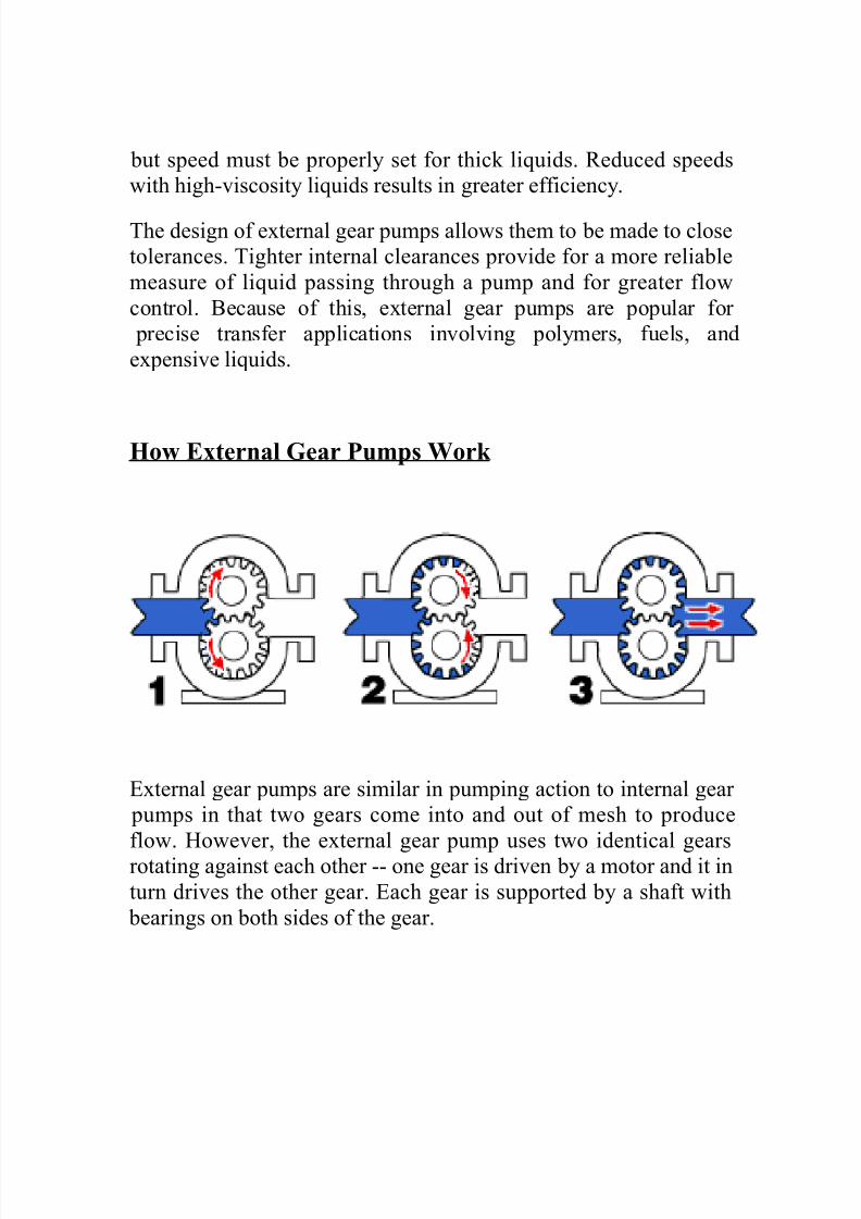
How External Gear Pumps Work
External gear pumps are similar in pumping action to internal gear
pumps in that two gears come into and out of mesh to produce
flow. However, the external gear pump uses two identical gears
rotating against each other -- one gear is driven by a motor and it in
turn drives the other gear. Each gear is supported by a shaft with
bearings on both sides of the gear.

8/8/2019 Project Final (Avas)
http://slidepdf.com/reader/full/project-final-avas 6/9
1. As the gears come out of mesh, they create expanding volume
on the inlet side of the pump. Liquid flows into the cavity and is
trapped by the gear teeth as they rotate.
2. Liquid travels around the interior of the casing in the pockets
between the teeth and the casing -- it does not pass between the
gears.
3. Finally, the meshing of the gears forces liquid through the outlet
port under pressure.
Because the gears are supported on both sides, external gear pumpsare quiet-running and are routinely used for high-pressure
applications such as hydraulic applications. With no overhung
bearing loads, the rotor shaft can't deflect and cause premature
wear.
Advantages
High speed.
Medium pressure.
No overhung bearing loads.
Relatively quiet operation.
Design accommodates wide variety of materials.
Disadvantages
Four bushings in liquid area.
No solids allowed.
Fixed End Clearances.

8/8/2019 Project Final (Avas)
http://slidepdf.com/reader/full/project-final-avas 7/9
Disadvantages
Four bushings in liquid area.
No solids allowed. Fixed End Clearances
Applications
Industrial and mobile applications
Fuel and lubrication
Metering
Mixing and
blending (
double pump)
Hydraulic applications
OEM configurations
Precise metering applications Low-volume transfers
Light or medium duty

8/8/2019 Project Final (Avas)
http://slidepdf.com/reader/full/project-final-avas 8/9
Materials Of Construction / Configuration Options
A composite external gear pump performs well in corrosive liquid applications
A composite external gear pump performs well in corrosive liquid
applications.
As the following list indicates, rotary pumps can be constructed in
a wide variety of materials. By precisely matching the materials of
construction with the liquid, superior life cycle performance will
result.
External gear pumps in particular can be engineered to the exact
need of corrosion-resistant pumps. By using readily-available
materials such as Ryton®, Ultimet®, Viton®, stainless steel, and
other materials, external gear pumps can be constructed to perform
very well in corrosive liquid applications. For example, compositeexternal gear pumps can handle Acetone, Sulphuric Acid, Tomato
Juice, Zinc Chloride, and hundreds of other corrosive liquids.
8/8/2019 Project Final (Avas)
http://slidepdf.com/reader/full/project-final-avas 9/9
External Gear
Externals (head, casing, bracket) - Iron, ductile iron, steel,
stainless steel.
Internals (rotor, idler) - Steel, stainless steel. Bushing - Carbon, bronze, silicon carbide.
Shaft Seal - Packing, lip seal, component mechanical seal,
magnetically-driven pump.
Composite External Gear
Externals (head, casing, bracket) - Ryton bracket and casing,
stainless steel internal pressure relief valve.
Internals (rotor, idler) - Ryton gears, PTFE gears, hardened
stainless steel shaft, and PTFE shaft.
Bushing - Carbon graphite, silicon carbide.
Shaft Seal - Packing, lip seal, component mechanical seal,
magnetically-driven pump