Programming Guide PROFINET
60
ENGINEERING TOMORROW Programming Guide PROFINET VLT ® AutomationDrive FC 360 vlt-drives.danfoss.com
Transcript of Programming Guide PROFINET

ENGINEERING TOMORROW
Programming GuidePROFINETVLT® AutomationDrive FC 360
vlt-drives.danfoss.com

Contents
1 Introduction 3
1.1 Purpose of the Manual 3
1.2 Additional Resources 3
1.3 Document and Software Version 3
1.4 Product Overview 3
1.5 Approvals and Certifications 4
1.6 Symbols, Abbreviations, and Conventions 4
2 Safety 5
2.1 Safety Symbols 5
2.2 Qualified Personnel 5
2.3 Safety Precautions 5
3 Configuration 7
3.1 Configure the PROFINET Network 7
3.2 Configure the Controller 7
3.3 Configure the Frequency Converter 9
4 Control 10
4.1 PPO Types 10
4.2 Process Data 11
4.3 Control Profile 13
4.4 PROFIdrive Control Profile 14
4.5 FC Drive Control Profile 18
5 Acyclic Communication (DP-V1) 21
5.1 Features of an IO Controller System 21
5.2 Features of an IO Supervisor System 21
5.3 Addressing Scheme 22
5.4 Acyclic Read/Write Request Sequence 23
5.5 Data Structure in the Acyclic Telegrams 24
5.6 Header 24
5.7 Parameter Block 24
5.8 Data Block 24
6 Parameters 26
6.1 Parameter Group 0-** Operation/Display 26
6.2 Parameter Group 8-** Communication and Option 26
6.3 Parameter Group 9-** PROFIdrive 28
6.4 Parameter Group 12-** Ethernet 32
6.5 PROFINET-specific Parameters 34
Contents Programming Guide
MG06G102 Danfoss A/S © 04/2017 All rights reserved. 1

6.6 Supported Object and Data Types 38
7 Application Examples 40
7.1 Example: Process Data with PPO Type 6 40
7.2 Example: Control Word Telegram Using Standard Telegram 1/PPO3 41
7.3 Example: Status Word Telegram Using Standard Telegram 1/PPO3 42
7.4 Example: PLC Programming 43
7.5 Example: PLC and Network Monitoring 44
8 Troubleshooting 48
8.1 No Response to Control Signals 48
8.2 Warnings and Alarms 50
8.2.1 Warning/Alarm Messages 52
Index 57
Contents PROFINET
2 Danfoss A/S © 04/2017 All rights reserved. MG06G102

1 Introduction
1.1 Purpose of the Manual
The PROFINET Programming Guide provides informationabout configuring the system, controlling the frequencyconverter, accessing parameters, programming, trouble-shooting, and some typical application examples.The programming guide is intended for use by qualifiedpersonnel, who are familiar with the VLT® frequencyconverters, PROFINET technology, and the PC or PLC that isused as a master in the system.Read the instructions before programming and follow theprocedures in this manual.
VLT® is a registered trademark.
1.2 Additional Resources
Resources available for the frequency converter andoptional equipment are:
• The VLT® AutomationDrive FC 360 Quick Guideprovides the necessary information for gettingthe frequency converter up and running.
• The VLT® AutomationDrive FC 360 Design Guideprovides detailed information about capabilitiesand functionality to design motor controlsystems.
• The VLT® AutomationDrive FC 360 ProgrammingGuide provides more details on working withparameters and many application examples.
Supplementary publications and manuals are availablefrom Danfoss. See drives.danfoss.com/knowledge-center/technical-documentation/ for listings.
1.3 Document and Software Version
This manual is regularly reviewed and updated. Allsuggestions for improvement are welcome. Table 1.1 showsthe document version and the corresponding softwareversion. The firmware version of the PROFINET interfacecan be read in parameter 15-61 Option SW Version.
Edition RemarksSoftwareversion
MG06G1xx The first edition of this manual. 3.0x
Table 1.1 Document and Software Version
1.4 Product Overview
This programming guide relates to PROFINET interface forVLT® AutomationDrive FC 360.
The PROFINET interface is designed to communicate withany system complying with the PROFINET schema version2.2 and 2.3 standards.Since the introduction in 2001, PROFINET has beenupdated to handle low and medium performancerequirements supported by PROFINET RT up to high-endservo performance in PROFINET IRT. PROFINET is theEthernet-based fieldbus offering and is the most scalableand versatile technology today.PROFINET provides the network tools to deploy standardEthernet technology for manufacturing applications whileenabling Internet and enterprise connectivity.
The PROFINET control cassette is intended for use withVLT® AutomationDrive FC 360.
TerminologyIn this manual, several terms for Ethernet are used.
• PROFINET is the term used to describe thePROFINET protocol.
• Ethernet is a common term used to describe thephysical layer of the network, and does not relateto the application protocol.
Introduction Programming Guide
MG06G102 Danfoss A/S © 04/2017 All rights reserved. 3
1 1

1.5 Approvals and Certifications
More approvals and certifications are available. For moreinformation, contact a local Danfoss partner.
1.6 Symbols, Abbreviations, andConventions
Abbreviation Definition
CC Control card
CTW Control word
DCP Discovery and configuration protocol
DHCP Dynamic host configuration protocol
EMC Electromagnetic compatibility
GSDML General station description mark-up language
I/O Input/output
IP Internet protocol
IRT Isochronous real time
LCP Local control panel
LED Light emitting diode
LSB Least significant bit
MAV Main actual value (actual speed)
MSB Most significant bit
MRV Main reference value
PC Personal computer
PCD Process control data
PLC Programmable logic controller
PNU Parameter number
PPO Process parameter object
REF Reference (= MRV)
RT Real time
STW Status word
Table 1.2 Symbols and Abbreviations
ConventionsNumbered lists indicate procedures.Bullet lists indicate other information and description ofillustrations.Italicized text indicates:
• Cross reference.
• Link.
• Parameter name.
• Parameter group.
• Parameter option.
Introduction PROFINET
4 Danfoss A/S © 04/2017 All rights reserved. MG06G102
11

2 Safety
2.1 Safety Symbols
The following symbols are used in this guide:
WARNINGIndicates a potentially hazardous situation that couldresult in death or serious injury.
CAUTIONIndicates a potentially hazardous situation that couldresult in minor or moderate injury. It can also be used toalert against unsafe practices.
NOTICEIndicates important information, including situations thatcan result in damage to equipment or property.
2.2 Qualified Personnel
Correct and reliable transport, storage, installation,operation, and maintenance are required for the trouble-free and safe operation of the frequency converter. Onlyqualified personnel are allowed to install or operate thisequipment.
Qualified personnel are defined as trained staff, who areauthorized to install, commission, and maintain equipment,systems, and circuits in accordance with pertinent laws andregulations. Additionally, the qualified personnel must befamiliar with the instructions and safety measuresdescribed in this document.
2.3 Safety Precautions
WARNINGHIGH VOLTAGEFrequency converters contain high voltage whenconnected to AC mains input, DC supply, or load sharing.Failure to perform installation, start-up, and maintenanceby qualified personnel can result in death or seriousinjury.
• Only qualified personnel must perform instal-lation, start-up, and maintenance.
WARNINGUNINTENDED STARTWhen the frequency converter is connected to AC mains,DC supply, or load sharing, the motor can start at anytime. Unintended start during programming, service, orrepair work can result in death, serious injury, orproperty damage. The motor can start with an externalswitch, a fieldbus command, an input reference signalfrom the LCP or LOP, via remote operation using MCT 10Set-up Software, or after a cleared fault condition.
To prevent unintended motor start:• Press [Off/Reset] on the LCP before
programming parameters.
• Disconnect the frequency converter from themains.
• Completely wire and assemble the frequencyconverter, motor, and any driven equipmentbefore connecting the frequency converter toAC mains, DC supply, or load sharing.
WARNINGDISCHARGE TIMEThe frequency converter contains DC-link capacitors,which can remain charged even when the frequencyconverter is not powered. High voltage can be presenteven when the warning LED indicator lights are off.Failure to wait the specified time after power has beenremoved before performing service or repair work canresult in death or serious injury.
• Stop the motor.
• Disconnect AC mains and remote DC-linksupplies, including battery back-ups, UPS, andDC-link connections to other frequencyconverters.
• Disconnect or lock PM motor.
• Wait for the capacitors to discharge fully. Theminimum waiting time is specified in thechapter Safety in the operating guide suppliedwith the frequency converter.
• Before performing any service or repair work,use an appropriate voltage measuring device tomake sure that the capacitors are fullydischarged.
Safety Programming Guide
MG06G102 Danfoss A/S © 04/2017 All rights reserved. 5
2 2

WARNINGLEAKAGE CURRENT HAZARDLeakage currents exceed 3.5 mA. Failure to ground thefrequency converter properly can result in death orserious injury.
• Ensure the correct grounding of the equipmentby a certified electrical installer.
WARNINGEQUIPMENT HAZARDContact with rotating shafts and electrical equipmentcan result in death or serious injury.
• Ensure that only trained and qualified personnelperform installation, start-up, and maintenance.
• Ensure that electrical work conforms to nationaland local electrical codes.
• Follow the procedures in this document.
CAUTIONINTERNAL FAILURE HAZARDAn internal failure in the frequency converter can resultin serious injury when the frequency converter is notproperly closed.
• Ensure that all safety covers are in place andsecurely fastened before applying power.
Safety PROFINET
6 Danfoss A/S © 04/2017 All rights reserved. MG06G102
22

3 Configuration
3.1 Configure the PROFINET Network
Ensure that all PROFINET devices connected to the samebus network have a unique station name (host name).
Set the PROFINET host name of the frequency convertervia parameter 12-08 Host Name.
3.2 Configure the Controller
3.2.1 GSDML File
To configure a PROFINET controller, the configuration toolneeds a GSDML file for each type of device on thenetwork. The GSDML file is a PROFINET xml file containingthe necessary communication set-up data for a device.Download the latest version of GSDML file atwww.danfoss.com/BusinessAreas/DrivesSolutions/profinet. Thename of the GSDML file may differ from what is describedin this manual.The following example shows how to configure thecontroller.
Frequency converter GSDML file
VLT® AutomationDrive FC 360GSDML-V2.3-Danfoss-FC360-20151212.xml
Table 3.1 GSDML file
When configuring the PROFINET controller, the first step isto import the GSDML file in the configuration tool. Thefollowing steps, outlined in Illustration 3.1, Illustration 3.2,and Illustration 3.3, show how to add a new GSDML file tothe Simatic Manager software tool. For each frequencyconverter, a GSDML file is typically imported once only,following the initial installation of the software tool.
130B
E934
.10
Illustration 3.1 Import the GSDML File in the ConfigurationTool
130B
E935
.10
Illustration 3.2 Add a New GSDML File to the Simatic ManagerSoftware Tool
The GSDML file is now imported and is accessible via thefollowing path in the hardware catalog:
130B
E936
.10
Illustration 3.3 Path in the Hardware Catalog
Open a project, set up the hardware, and add a PROFINETmaster system. Select Danfoss FC PN, then drag and dropit onto the PROFINET IO system.
To enter the device name, open the properties for theinserted frequency converter. See Illustration 3.4.
Configuration Programming Guide
MG06G102 Danfoss A/S © 04/2017 All rights reserved. 7
3 3

130B
E937
.10
Illustration 3.4 Open the Properties for the InsertedFrequency Converter to Enter the Device Name
NOTICEThe name must match the name in parameter 12-08 HostName. If the check mark Assign IP address via the IOcontroller is set, the controller downloads the IP addressto the IO device with the corresponding device name.The IP address is stored in the non-volatile memory ofthe frequency converter.
130B
E938
.10
Illustration 3.5 Set Up the Hardware and Add a PROFINETMaster System
The next step is to set up the peripheral input and outputdata. Data set-up in the peripheral area is transmittedcyclically via telegrams/PPO types. In the example below, aPPO type 6 is dragged and dropped to slot 1.
130B
E939
.10
Illustration 3.6 Set up the Peripheral Input and Output Data
The configuration tool automatically assigns addresses inthe peripheral address area. In this example, the input andoutput area have the following configuration:
PPO type 6
PCD wordnumber
0 1 2 3
Inputaddress
256–257 258–259 260–261 262–263
Set-up STW MAVParameter 9-16 PCD ReadConfiguration
Parameter 9-16 PCD ReadConfiguration
Table 3.2 PCD Read (Frequency Converter to PLC)
PCD wordnumber
0 1 2 3
Outputaddress
256–257 258–259 260–261 262–263
Set-up CTW MRVParameter 9-15 PCD WriteConfiguration
Parameter 9-15 PCD WriteConfiguration
Table 3.3 PCD Write (PLC to Frequency Converter)
Assign the PCDs via parameter 9-16 PCD Read Configurationfor inputs and parameter 9-15 PCD Write Configuration foroutputs.
Download the configuration file to the PLC. The PROFINETsystem starts the data exchange when the PLC is set toRun mode.
Configuration PROFINET
8 Danfoss A/S © 04/2017 All rights reserved. MG06G102
33
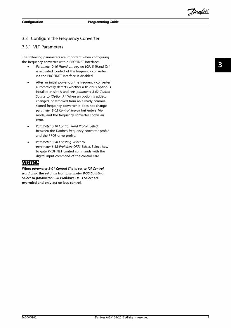
3.3 Configure the Frequency Converter
3.3.1 VLT Parameters
The following parameters are important when configuringthe frequency converter with a PROFINET interface:
• Parameter 0-40 [Hand on] Key on LCP. If [Hand On]is activated, control of the frequency convertervia the PROFINET interface is disabled.
• After an initial power-up, the frequency converterautomatically detects whether a fieldbus option isinstalled in slot A and sets parameter 8-02 ControlSource to [Option A]. When an option is added,changed, or removed from an already commis-sioned frequency converter, it does not changeparameter 8-02 Control Source but enters Tripmode, and the frequency converter shows anerror.
• Parameter 8-10 Control Word Profile. Selectbetween the Danfoss frequency converter profileand the PROFIdrive profile.
• Parameter 8-50 Coasting Select to parameter 8-58 Profidrive OFF3 Select. Select howto gate PROFINET control commands with thedigital input command of the control card.
NOTICEWhen parameter 8-01 Control Site is set to [2] Controlword only, the settings from parameter 8-50 CoastingSelect to parameter 8-58 Profidrive OFF3 Select areoverruled and only act on bus control.
Configuration Programming Guide
MG06G102 Danfoss A/S © 04/2017 All rights reserved. 9
3 3

4 Control
4.1 PPO Types
The PROFINET profile for frequency converters specifies anumber of standard telegrams and provides space forvendor-specific telegrams. The PROFIdrive profile forfrequency converters is suitable for data exchangebetween a process controller (for example PLC) and afrequency converter. All telegrams are defined for cyclicdata transfer of high-priority data.
Pure process data objectsPPO types 3, 4, 6, 7, and 8 are pure process data objectsfor applications requiring no cyclic parameter access. ThePLC sends out process control data, and the frequencyconverter then responds with a PPO of the same length,containing process status data.
Illustration 4.1 shows the available PPO types:• PCD 1: The first 2 bytes of the process data area
(PCD 1) comprise a fixed part present in all PPOtypes.
• PCD 2: The next 2 bytes are fixed for PCD writeentries (see parameter 9-15 PCD Write Configu-ration [1]), but configurable for PCD read entries(see parameter 9-16 PCD Read Configuration [1]).
• PCD 3–10: In the remaining bytes, the processdata can be parameterized with process signals,see parameter 9-23 Parameters for Signals.
The setting in parameter 9-15 PCD Write Configurationdetermines the signals for transmission (request) from themaster to the frequency converter.
The setting in parameter 9-16 PCD Read Configurationdetermines the signals for transmission (response) from thefrequency converter to the master.
Select the PPO type in the master configuration. Theselection is automatically recorded in the frequencyconverter. No manual setting of PPO types in thefrequency converter is required. Read the current PPO typein parameter 9-22 Telegram Selection. The setting [1]Standard telegram 1 is equivalent to PPO type 3.
In addition, all PPO types can be set up as word-consistentor module-consistent. The process data area can be word-consistent or module-consistent, whereas the parameterchannel must always be module-consistent.
• Word-consistent data is transmitted as individual,independent words between the PLC and thefrequency converter.
• Module-consistent data is transmitted as sets ofinterrelated words transferred simultaneouslybetween the PLC and the frequency converter.
Standard telegram
1
PPO 6
PPO 7
PPO 8
Danfoss telegram
(The old PPO type 3)
CTW/STW REF/MAVPCD 2Read/Write
PCD 3Read/Write
PCD 4Read/Write
PCD 5Read/Write
PPO 4
CTW/STW REF/MAVPCD 2Read/Write
PCD 3Read/Write
CTW/STW REF/MAVPCD 2Read/Write
PCD 3Read/Write
PCD 4Read/Write
PCD 5Read/Write
PCD 6Read/Write
PCD 7Read/Write
PCD 8Read/Write
PCD 9Read/Write
CTW/STW REF/MAVPCD 2Read/Write
PCD 3Read/Write
PCD 4Read/Write
PCD 5Read/Write
PCD 6Read/Write
PCD 7Read/Write
CTW/STW REF/MAV
CTW/STW REF/MAV
PPO 3
130B
E941
.10
Illustration 4.1 Available PPO Types
Control PROFINET
10 Danfoss A/S © 04/2017 All rights reserved. MG06G102
44

4.2 Process Data
Use the process data part of the PPO to control andmonitor the frequency converter via the PROFINET.
4.2.1 PCD
Control word (CTW) according to PROFIdrive profile:Control words consist of 16 bits. The meaning of each bitis explained in and . The following bit pattern sets allnecessary start commands:0000 0100 0111 1111 = 047F hex.1)
0000 0100 0111 1110 = 047E hex.1)
0000 0100 0111 1111 = 047F hex.
1) For restart after power-up:• Set bits 1 and 2 of the CTW to 1.
• Toggle bit 0 0–1.
These values are for bytes 9 and 10 in Table 4.1.Quick stop: 0000 0100 0110 1111 = 046F hex.Stop: 0000 0100 0011 1111 = 043F hex.
4.2.2 MRV
MRV is the speed reference with data format Standardizedvalue. 0 hex = 0% and 4000 hex = 100%.In the example, 2000 hex is used corresponding to 50% ofthe maximum frequency in parameter 3-03 MaximumReference. See the values for bytes 11 and 12 in Table 4.1.The whole PPO therefore has the following values in hex:
Byte Value
PCD
CTW 9 04
CTW 10 7F
MRV 11 20
MVR 12 00
Table 4.1 Request Example: PPO Values in Hex
The process data within the PCD part acts immediatelyupon the frequency converter and can be updated fromthe master as quickly as possible.
Table 4.2 shows a positive response to the request examplefrom Table 4.1.
Byte Value
PCD
STW 9 0F
STW 10 07
MAV 11 20
MAR 12 00
Table 4.2 Response Example: Positive Response
The PCD part responds according to the state and parame-terization of the frequency converter.
PCD part response:• STW: 0F07 hex means that the motor is running
and there are no warnings or faults.
• MAV: 2000 hex indicates that the outputfrequency is 50% of the maximum reference.
Table 4.3 shows a negative response to the requestexample from Table 4.1.
Byte Value
PCD
STW 9 0F
STW 10 07
MAV 11 20
MAR 12 00
Table 4.3 Response Example: Negative Response
4.2.3 Process Control Data
Process control data (PCD) is the process data sent fromthe PLC to the frequency converter.
Master/slave
1 2 3 ....... 10
CTW MRV PCD ....... PCD
PCD write
Table 4.4 Process Control Data
PCD 1 contains a 16-bit control word, and each bit controlsa specific function of the frequency converter. See chapter 4.3 Control Profile.
PCD 2 contains a 16-bit speed setpoint in percentageformat. See chapter 4.2.5 Reference Handling.
The settings in parameter 9-15 PCD Write Configuration andparameter 9-16 PCD Read Configuration define the contentof PCD 3 to PCD 10.
Control Programming Guide
MG06G102 Danfoss A/S © 04/2017 All rights reserved. 11
4 4

4.2.4 Process Status Data
Process status data is the process data sent from thefrequency converter and contains information about thecurrent state.
Slave/master
1 2 3 ...... 10
STW MAV PCD ...... PCD
PCD read
Table 4.5 Process Status Data
PCD 1 contains a 16-bit status word, and each bit containsinformation regarding a possible state of the frequencyconverter.
PCD 2 contains each default value of the frequencyconverter’s current speed in percentage format (see chapter 4.2.5 Reference Handling). PCD 2 can be configuredto contain other process signals.
The settings in parameter 9-16 PCD Read Configurationdefine the content of PCD 3–10.
4.2.5 Reference Handling
The reference handling is an advanced mechanism thatsums up references from different sources as shown inIllustration 4.2.
For more information on reference handling, refer to thefrequency converter’s design guide.
Illustration 4.2 Reference
The reference or speed setpoint is sent via PROFINET andis always transmitted to the frequency converter inpercentage format as integers shown in hexadecimal (0–4000 hex).
The reference (MRV) and feedback (MAV) are always scaledequally. The setting of parameter 3-00 Reference Rangedetermines the scaling of the reference and feedback(MAV), see Illustration 4.3.
-100%(C000 hex)
0%(0 hex)
100%(4000 hex)
P 3-00 set to [1] -Max to +Max
P 3-03Max reference
0 P 3-03Max reference
0%(0 hex)
100%(4000 hex)
P 3-00 set to [0] Min - Max
P 3-02Min reference
P 3-03Max reference
130B
A19
8.10
Illustration 4.3 Reference (MRV) and Feedback (MAV), Scaled
NOTICEWhen parameter 3-00 Reference Range is set to [0] Min -Max, a negative reference is handled as 0%.
The actual output of the frequency converter is limited bythe speed limit parameters Motor Low/High Speed Limit[RPM/Hz] in parameter 4-11 Motor Speed Low Limit [RPM] toparameter 4-14 Motor Speed High Limit [Hz].The final speed limit is set in parameter 4-19 Max OutputFrequency.
Table 4.6 lists the reference (MRV) and the feedback (MAV)formats.
MRV/MAV Integer in hex Integer in decimal
100% 4000 16384
75% 3000 12288
50% 2000 8192
25% 1000 4096
0% 0 0
-25% F000 -4096
-50% E000 -8192
-75% D000 -12288
-100% C000 -16384
Table 4.6 Reference/Feedback (MRV/MAV) Format
NOTICENegative numbers are formed as complement of 2.
NOTICEThe data type for MRV and MAV is an N2 16-bitstandardized value, expressing a range from -200% to+200% (8001 to 7FFF).
Control PROFINET
12 Danfoss A/S © 04/2017 All rights reserved. MG06G102
44

Example
The following settings determine the speed as shown inTable 4.7:
• Parameter 1-00 Configuration Mode set to [0]Speed open loop.
• Parameter 3-00 Reference Range set to [0] Min-Max.
• Parameter 3-02 Minimum Reference set to 0 Hz.
• Parameter 3-03 Maximum Reference set to 50 Hz.
MRV/MAV Actual speed [Hz]
0% 0 hex 0
25% 1000 hex 12.5
50% 2000 hex 25
75% 3000 hex 37.5
100% 4000 hex 50
Table 4.7 Actual Speed for MRV/MAV
4.2.6 Process Control Operation
In process control operation, parameter 1-00 ConfigurationMode is set to [3] Process.The reference range in parameter 3-00 Reference Range isalways [0] Min - Max.
• MRV is the process setpoint.
• MAV expresses the actual process feedback (range±200%).
4.2.7 Influence of the Digital InputTerminals on FC Control Mode
In parameter 8-50 Coasting Select to parameter 8-58 Profidrive OFF3 Select, set the influence ofthe digital input terminals on the control of the frequencyconverter.
NOTICEThe setting of parameter 8-01 Control Site overrules thesettings in parameter 8-50 Coasting Select to parameter 8-58 Profidrive OFF3 Select.
Program each of the digital input signals to logic AND,logic OR, or to have no relation to the corresponding bit inthe control word. In this way, the following signal sourcesinitiate a specific control command, for example stop/coast:
• Fieldbus only.
• Fieldbus AND digital input.
• Either fieldbus OR digital input terminal.
NOTICETo control the frequency converter via PROFINET, setparameter 8-50 Coasting Select to either [1] Bus or [2]Logic AND. Then set parameter 8-01 Control Site to [0]Digital and ctrl.word or [2] Controlword only.
For more detailed information and examples of logicalrelationship options, see chapter 8 Troubleshooting.
4.3 Control Profile
Control the frequency converter according to:• The PROFIdrive profile, see chapter 4.4 PROFIdrive
Control Profile, or
• The Danfoss FC control, see chapter 4.5 FC DriveControl Profile.
Select the control profile in parameter 8-10 Control WordProfile. The choice of profile affects the control word andstatus word only.
Chapter 4.4 PROFIdrive Control Profile and chapter 4.5 FCDrive Control Profile provide a detailed description ofcontrol and status data.
Control Programming Guide
MG06G102 Danfoss A/S © 04/2017 All rights reserved. 13
4 4
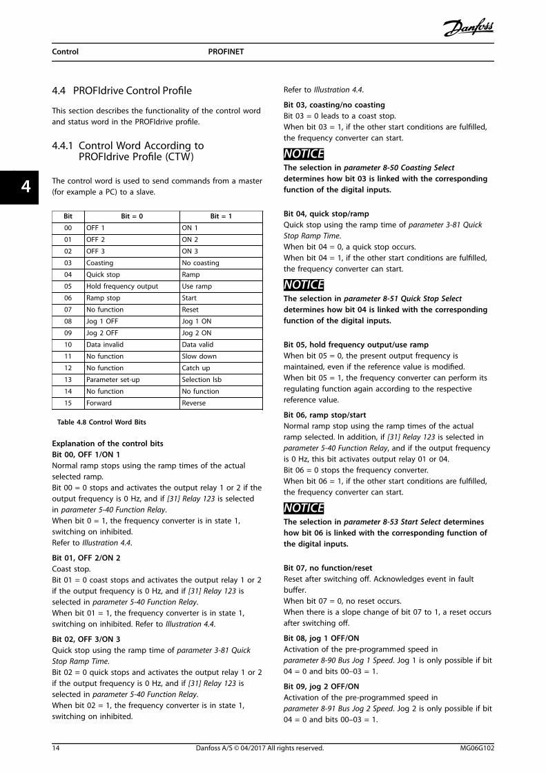
4.4 PROFIdrive Control Profile
This section describes the functionality of the control wordand status word in the PROFIdrive profile.
4.4.1 Control Word According toPROFIdrive Profile (CTW)
The control word is used to send commands from a master(for example a PC) to a slave.
Bit Bit = 0 Bit = 1
00 OFF 1 ON 1
01 OFF 2 ON 2
02 OFF 3 ON 3
03 Coasting No coasting
04 Quick stop Ramp
05 Hold frequency output Use ramp
06 Ramp stop Start
07 No function Reset
08 Jog 1 OFF Jog 1 ON
09 Jog 2 OFF Jog 2 ON
10 Data invalid Data valid
11 No function Slow down
12 No function Catch up
13 Parameter set-up Selection lsb
14 No function No function
15 Forward Reverse
Table 4.8 Control Word Bits
Explanation of the control bitsBit 00, OFF 1/ON 1Normal ramp stops using the ramp times of the actualselected ramp.Bit 00 = 0 stops and activates the output relay 1 or 2 if theoutput frequency is 0 Hz, and if [31] Relay 123 is selectedin parameter 5-40 Function Relay.When bit 0 = 1, the frequency converter is in state 1,switching on inhibited.Refer to Illustration 4.4.
Bit 01, OFF 2/ON 2Coast stop.Bit 01 = 0 coast stops and activates the output relay 1 or 2if the output frequency is 0 Hz, and if [31] Relay 123 isselected in parameter 5-40 Function Relay.When bit 01 = 1, the frequency converter is in state 1,switching on inhibited. Refer to Illustration 4.4.
Bit 02, OFF 3/ON 3Quick stop using the ramp time of parameter 3-81 QuickStop Ramp Time.Bit 02 = 0 quick stops and activates the output relay 1 or 2if the output frequency is 0 Hz, and if [31] Relay 123 isselected in parameter 5-40 Function Relay.When bit 02 = 1, the frequency converter is in state 1,switching on inhibited.
Refer to Illustration 4.4.
Bit 03, coasting/no coastingBit 03 = 0 leads to a coast stop.When bit 03 = 1, if the other start conditions are fulfilled,the frequency converter can start.
NOTICEThe selection in parameter 8-50 Coasting Selectdetermines how bit 03 is linked with the correspondingfunction of the digital inputs.
Bit 04, quick stop/rampQuick stop using the ramp time of parameter 3-81 QuickStop Ramp Time.When bit 04 = 0, a quick stop occurs.When bit 04 = 1, if the other start conditions are fulfilled,the frequency converter can start.
NOTICEThe selection in parameter 8-51 Quick Stop Selectdetermines how bit 04 is linked with the correspondingfunction of the digital inputs.
Bit 05, hold frequency output/use rampWhen bit 05 = 0, the present output frequency ismaintained, even if the reference value is modified.When bit 05 = 1, the frequency converter can perform itsregulating function again according to the respectivereference value.
Bit 06, ramp stop/startNormal ramp stop using the ramp times of the actualramp selected. In addition, if [31] Relay 123 is selected inparameter 5-40 Function Relay, and if the output frequencyis 0 Hz, this bit activates output relay 01 or 04.Bit 06 = 0 stops the frequency converter.When bit 06 = 1, if the other start conditions are fulfilled,the frequency converter can start.
NOTICEThe selection in parameter 8-53 Start Select determineshow bit 06 is linked with the corresponding function ofthe digital inputs.
Bit 07, no function/resetReset after switching off. Acknowledges event in faultbuffer.When bit 07 = 0, no reset occurs.When there is a slope change of bit 07 to 1, a reset occursafter switching off.
Bit 08, jog 1 OFF/ONActivation of the pre-programmed speed inparameter 8-90 Bus Jog 1 Speed. Jog 1 is only possible if bit04 = 0 and bits 00–03 = 1.
Bit 09, jog 2 OFF/ONActivation of the pre-programmed speed inparameter 8-91 Bus Jog 2 Speed. Jog 2 is only possible if bit04 = 0 and bits 00–03 = 1.
Control PROFINET
14 Danfoss A/S © 04/2017 All rights reserved. MG06G102
44

Bit 10, data invalid/validTells the frequency converter whether to use or ignore thecontrol word.Bit 10 = 0 ignores the control word, making it possible toturn off the control word when updating/readingparameters.Bit 10 = 1 uses the control word. This function is relevantbecause the control word is always contained in thetelegram, regardless of which type of telegram is used.
Bit 11, no function/slow downUsed to reduce the speed reference value by the amountgiven in parameter 3-12 Catch up/slow Down Value.When bit 11 = 0, no modification of the reference valueoccurs.When bit 11 = 1, the reference value is reduced.
Bit 12, no function/catch upUsed to increase the speed reference value by the amountgiven in parameter 3-12 Catch up/slow Down Value.When bit 12 = 0, no modification of the reference valueoccurs.When bit 12 = 1, the reference value is increased.If both slowing down and accelerating are activated (bits11 and 12 = 1), slowing down has priority, and the speedreference value is reduced.
Bits 13, set-up selectionBits 13 is used to select between the 2 parameter set-upsaccording to Table 4.9.
The function is only possible if [9] Multi Set-up has beenselected in parameter 0-10 Active Set-up. The selection inparameter 8-55 Set-up Select determines how bit 13 islinked with the corresponding function of the digitalinputs. Changing set-up while the frequency converter isrunning is only possible if the set-ups have been linked inparameter 0-12 This Set-up Linked to.
Set-up Bit 13
1 0
2 1
Table 4.9 Parameter Set-ups
Bit 14, not usedBit 15, no function/reverseBit 15 = 0 causes no reversing.Bit 15 = 1 causes reversing.
NOTICEIn the factory setting, reversing is set to [0] Digital in parameter 8-54 Reversing Select.
NOTICEBit 15 causes reversing only when Ser. communication,Logic or, or Logic and is selected.
4.4.2 Status Word According to PROFIdriveProfile (STW)
The status word is used to notify a master (for example aPC) about the status of a slave.
Bit Bit = 0 Bit = 1
00 Control not ready Control ready
01Frequency converternot ready
Frequency converter ready
02 Coasting Enable
03 No error Trip
04 OFF 2 ON 2
05 OFF 3 ON 3
06 Start possible Start not possible
07 No warning Warning
08 Speed ≠ reference Speed = reference
09 Local operation Bus control
10 Out of frequency limit Frequency limit ok
11 No operation In operation
12Frequency converterOK
Stopped, auto-start
13 Voltage OK Voltage exceeded
14 Torque OK Torque exceeded
15 Thermal OK Limit exceeded
Table 4.10 Status Word Bits
Explanation of the status bitsBit 00, control not ready/readyWhen bit 00 = 0, bit 00, 01, or 02 of the control word is 0(OFF 1, OFF 2, or OFF 3) - or the frequency converter isswitched off (tripped).When bit 00 = 1, the frequency converter control is ready,but power is not necessarily supplied to the unit (in caseof a 24 V external supply of the control system).
Bit 01, VLT not ready/readySame significance as bit 00, however, power is supplied tothe unit. The frequency converter is ready when it receivesthe necessary start signals.
Bit 02, coasting/enableWhen bit 02 = 0, bit 00, 01, or 02 of the control word is 0(OFF 1, OFF 2, OFF 3, or coasting) - or the frequencyconverter is switched off (trip).When bit 02 = 1, bit 00, 01, or 02 of the control word is 1,and the frequency converter has not tripped.
Bit 03, no error/tripWhen bit 03 = 0, no error condition exists in the frequencyconverter.When bit 03 = 1, the frequency converter has tripped andrequires a reset signal before it can start.
Bit 04, ON 2/OFF 2When bit 01 of the control word is 0, bit 04 = 0.When bit 01 of the control word is 1, bit 04 = 1.
Control Programming Guide
MG06G102 Danfoss A/S © 04/2017 All rights reserved. 15
4 4
Bit 05, ON 3/OFF 3When bit 02 of the control word is 0, bit 05 = 0.When bit 02 of the control word is 1, bit 05 = 1.
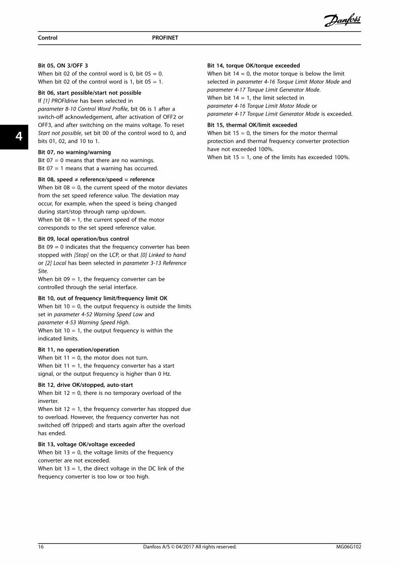
Bit 06, start possible/start not possibleIf [1] PROFIdrive has been selected inparameter 8-10 Control Word Profile, bit 06 is 1 after aswitch-off acknowledgement, after activation of OFF2 orOFF3, and after switching on the mains voltage. To resetStart not possible, set bit 00 of the control word to 0, andbits 01, 02, and 10 to 1.
Bit 07, no warning/warningBit 07 = 0 means that there are no warnings.Bit 07 = 1 means that a warning has occurred.
Bit 08, speed ≠ reference/speed = referenceWhen bit 08 = 0, the current speed of the motor deviatesfrom the set speed reference value. The deviation mayoccur, for example, when the speed is being changedduring start/stop through ramp up/down.When bit 08 = 1, the current speed of the motorcorresponds to the set speed reference value.
Bit 09, local operation/bus controlBit 09 = 0 indicates that the frequency converter has beenstopped with [Stop] on the LCP, or that [0] Linked to handor [2] Local has been selected in parameter 3-13 ReferenceSite.When bit 09 = 1, the frequency converter can becontrolled through the serial interface.
Bit 10, out of frequency limit/frequency limit OKWhen bit 10 = 0, the output frequency is outside the limitsset in parameter 4-52 Warning Speed Low andparameter 4-53 Warning Speed High.When bit 10 = 1, the output frequency is within theindicated limits.
Bit 11, no operation/operationWhen bit 11 = 0, the motor does not turn.When bit 11 = 1, the frequency converter has a startsignal, or the output frequency is higher than 0 Hz.
Bit 12, drive OK/stopped, auto-startWhen bit 12 = 0, there is no temporary overload of theinverter.When bit 12 = 1, the frequency converter has stopped dueto overload. However, the frequency converter has notswitched off (tripped) and starts again after the overloadhas ended.
Bit 13, voltage OK/voltage exceededWhen bit 13 = 0, the voltage limits of the frequencyconverter are not exceeded.When bit 13 = 1, the direct voltage in the DC link of thefrequency converter is too low or too high.
Bit 14, torque OK/torque exceededWhen bit 14 = 0, the motor torque is below the limitselected in parameter 4-16 Torque Limit Motor Mode andparameter 4-17 Torque Limit Generator Mode.When bit 14 = 1, the limit selected inparameter 4-16 Torque Limit Motor Mode orparameter 4-17 Torque Limit Generator Mode is exceeded.
Bit 15, thermal OK/limit exceededWhen bit 15 = 0, the timers for the motor thermalprotection and thermal frequency converter protectionhave not exceeded 100%.When bit 15 = 1, one of the limits has exceeded 100%.
Control PROFINET
16 Danfoss A/S © 04/2017 All rights reserved. MG06G102
44

4.4.3 PROFIdrive State Transition Diagram
In the PROFIdrive control profile, the control bits:• 0–3 perform the basic start-up/power-down functions.
• 4–15 perform application-oriented control.
Illustration 4.4 shows the basic state transition diagram where control bits 0–3 control the transitions, and the correspondingstatus bit indicates the actual state. The black bullets indicate the priority of the control signals where fewer bullets indicatelower priority, and more bullets indicate higher priority.
130B
D80
6.10
Pulses Disabled
Coast StopSTW bit 1=false
Quick Stop
Quick StopSTW bit 2=false
OFFSTW bit 0=false
ONSTW bit 0=true
Ramp Stop
Quick StopSTW bit 2=false
S3: Switching ON inhibited STW bit 6=true; 0, 1, 2=false
OFF AND No Coast StopAND No Quick Stop
STW bit 0=falseAND bit 1=trueAND bit 2=true
Coast StopOR Quick Stop
STW bit 1=falseOR bit 2=false
Coast StopOR Quick Stop
STW bit 1=falseOR bit 2=false
Coast StopSTW bit 1=false
Enable Operation
STW bit 3=true
1st priority2nd priority3rd priority
Disable Operation
STW bit 3=false
ON STW bit 0=true
OFFSTW bit 0=true
PulsesDisabled
S2: Ready For Switching ONSTW bit 0=true; 1, 2, 6=false
S5: Switching OFF
STW bit 0, 1=truebit 2, 6=false
S3: Switched ONSTW bit 0, 1=true; 2, 6=false
S4: OperationSTW bit 0, 1,2=true; 6=false
Illustration 4.4 PROFIdrive State Transition Diagram
Control Programming Guide
MG06G102 Danfoss A/S © 04/2017 All rights reserved. 17
4 4

4.5 FC Drive Control Profile
4.5.1 Control Word According to FC Profile(CTW)
To select Danfoss FC protocol in the control word, setparameter 8-10 Control Word Profile to [0] FC profile. Use thecontrol word to send commands from a master (PLC or PC)to a slave (frequency converter).
Bit Bit value = 0 Bit value = 1
00 Reference value External selection lsb
01 Reference value External selection msb
02 DC brake Ramp
03 Coasting No coasting
04 Quick stop Ramp
05 Hold output frequency Use ramp
06 Ramp stop Start
07 No function Reset
08 No function Jog
09 Ramp 1 Ramp 2
10 Data invalid Data valid
11 No function Relay 01 active
12 No function Relay 02 active
13 Parameter set-up Selection lsb
14 No function No function
15 Forward Reverse
Table 4.11 Bit Values for FC Control Word
Explanation of the control bitsBits 00/01, reference valueUse bits 00 and 01 to select between the 4 referencevalues, which are pre-programmed in parameter 3-10 PresetReference according to Table 4.12.
NOTICEIn parameter 8-56 Preset Reference Select, a selection ismade to define how bit 00/01 gates with thecorresponding function on the digital inputs.
Bit01
Bit00
Programmedreference value
Parameter
0 0 1 [0] Parameter 3-10 Preset Reference
0 1 2 [1] Parameter 3-10 Preset Reference
1 0 3 [2] Parameter 3-10 Preset Reference
1 1 4 [3] Parameter 3-10 Preset Reference
Table 4.12 Programmed Reference Values for Bits
Bit 02, DC brakeBit 02 = 0 leads to DC braking and stop. Braking currentand duration are set in parameter 2-01 DC Brake Currentand parameter 2-02 DC Braking Time.Bit 02 = 1 leads to ramping.
Bit 03, coastingBit 03 = 0 causes the frequency converter immediately tocoast the motor to a standstill.Bit 03 = 1 enables the frequency converter to start themotor if the other starting conditions have been fulfilled.
NOTICEIn parameter 8-50 Coasting Select, a selection is made todefine how bit 03 gates with the corresponding functionon a digital input.
Bit 04, quick stopBit 04 = 0 quick stops the frequency converter and rampsthe motor speed down to stop via parameter 3-81 QuickStop Ramp Time.Bit 04 = 1 makes the frequency converter ramp the motorspeed down to stop via parameter 3-42 Ramp 1 RampDown Time or parameter 3-52 Ramp 2 Ramp Down Time.
Bit 05, hold output frequencyBit 05 = 0 freezes the present output frequency (in Hz).The frozen output frequency can only be changed with thedigital inputs (parameter 5-10 Terminal 18 Digital Input toparameter 5-15 Terminal 33 Digital Input) programmed to[21] Speed up and [22] Speed down.Bit 05 = 1 uses ramp.
Bit 06, ramp stop/startBit 06 = 0 stops the frequency converter and the motorspeed ramps down to stop via the selected ramp-downparameter.Bit 06 = 1 allows the frequency converter to start themotor if the other starting conditions have been fulfilled.
NOTICEIn parameter 8-53 Start Select, define how bit 06 rampstop/start gates with the corresponding function on adigital input.
Bit 07, resetBit 07 = 0 does not cause a reset.Bit 07 = 1 resets a trip. Reset is activated on the signal’sleading edge, that is, when changing from logic 0 to logic1.
Bit 08, jogBit 08 = 0, no function.Bit 08 = 1, parameter 3-19 Jog Speed [RPM] determines theoutput frequency.
Bit 09, selection of ramp 1/2Bit 09 = 0, ramp 1 is active (parameter 3-40 Ramp 1 Type toparameter 3-47 Ramp 1 S-ramp Ratio at Decel. Start).Bit 09 = 1, ramp 2 is active (parameter 3-50 Ramp 2 Type toparameter 3-57 Ramp 2 S-ramp Ratio at Decel. Start).
Control PROFINET
18 Danfoss A/S © 04/2017 All rights reserved. MG06G102
44

Bit 10, data not valid/data validTell the frequency converter to use or ignore the controlword.Bit 10 = 0 ignores the control word.Bit 10 = 1 uses the control word. This function is relevantbecause the control word is always contained in thetelegram, regardless of which type of telegram is used.Thus, it is possible to turn off the control word if it is notneeded when updating or reading parameters.
Bit 11, relay 01Bit 11 = 0, relay 01 is not activated.Bit 11 = 1, relay 01 is activated, provided control word bit11 is selected in parameter 5-40 Function Relay.
Bit 12, relay 02Bit 12 = 0, relay 02 is not activated.Bit 12 = 1, relay 02 is activated, provided [37] Control wordbit 12 is selected in parameter 5-40 Function Relay.
Bits 13, set-up selectionUse bit 13 to select from the 2 set-ups according toTable 4.13.
The function is only possible when [9] Multi Set-ups isselected in parameter 0-10 Active Set-up.
Set-up Bit 13
1 0
2 1
Table 4.13 Set-up selection
NOTICEIn parameter 8-55 Set-up Select, define how bit 13 gateswith the corresponding function on the digital inputs.
Bit 14, not usedBit 15, reverseBit 15 = 0 means no reversing.Bit 15 = 1 means reversing.
4.5.2 Status Word According to FC Profile(STW)
The status word is used to inform the master (for examplea PC) of the operating mode of the slave (frequencyconverter).
Refer to chapter 7 Application Examples for an example of astatus word telegram using PPO type 3.
Bit Bit = 0 Bit = 1
00 Control not ready Control ready
01Frequency converter notready
Frequency converter ready
02 Coasting Enable
03 No error Trip
04 No error Error (no trip)
05 Reserved –
06 No error Trip lock
07 No warning Warning
08 Speed ≠ reference Speed = reference
09 Local operation Bus control
10 Out of frequency limit Frequency limit OK
11 No operation In operation
12 Frequency converter OK Stopped, auto-start
13 Voltage OK Voltage exceeded
14 Torque OK Torque exceeded
15 Thermal OK Limit exceeded
Table 4.14 Definition of Status Bits
Explanation of the status bitsBit 00, control not ready/readyBit 00 = 0, the frequency converter has tripped.Bit 00 = 1, the frequency converter controls are ready, butthe power component is not necessarily receiving anypower (in case of a 24 V external supply to controls).
Bit 01, frequency converter readyBit 01 = 0, the frequency converter is not ready foroperation.Bit 01 = 1, the frequency converter is ready for operation,but there is an active coasting command via the digitalinputs or via serial communication.
Bit 02, coasting stopBit 02 = 0, the frequency converter has released the motor.Bit 02 = 1, the frequency converter can start the motorwhen a start command is given.
Bit 03, no error/tripBit 03 = 0, the frequency converter is not in fault mode.Bit 03 = 1, the frequency converter is tripped, and a resetsignal is required to re-establish operation.
Bit 04, no error/error (no trip)Bit 04 = 0, the frequency converter is not in fault mode.Bit 04 = 1, there is a frequency converter error but no trip.
Control Programming Guide
MG06G102 Danfoss A/S © 04/2017 All rights reserved. 19
4 4

Bit 05, not usedBit 05 is not used in the status word.
Bit 06, no error/triplockBit 06 = 0, the frequency converter is not in fault mode.Bit 06 = 1, the frequency converter is tripped and locked.
Bit 07, no warning/warningBit 07 = 0, there are no warnings.Bit 07 = 1, a warning has occurred.
Bit 08, speed ≠ reference/speed = referenceBit 08 = 0, the motor runs, but the present speed isdifferent from the preset speed reference. It could, forexample, be the case while the speed ramps up/downduring start/stop.Bit 08 = 1, the present motor speed matches the presetspeed reference.
Bit 09, local operation/bus controlBit 09 = 0, [Stop/Reset] is pressed on the LCP, or [2] Local isselected in parameter 3-13 Reference Site. It is not possibleto control the frequency converter via serial communi-cation.Bit 09 = 1, it is possible to control the frequency convertervia the fieldbus/serial communication.
Bit 10, out of frequency limitBit 10 = 0, the output frequency has reached the value inparameter 4-11 Motor Speed Low Limit [RPM] orparameter 4-13 Motor Speed High Limit [RPM].Bit 10 = 1, the output frequency is within the definedlimits.
Bit 11, no operation/in operationBit 11 = 0, the motor does not run.Bit 11 = 1, the frequency converter has a start signal or theoutput frequency is higher than 0 Hz.
Bit 12, frequency converter OK/stopped, auto-startBit 12 = 0, there is no temporary overtemperature in thefrequency converter.Bit 12 = 1, the frequency converter has stopped because ofovertemperature, but it has not tripped and resumesoperation once the temperature is within the definedlimits.
Bit 13, voltage OK/limit exceededBit 13 = 0, there are no voltage warnings.Bit 13 = 1, the DC voltage in the frequency converter’s DClink is too low or too high.
Bit 14, torque OK/limit exceededBit 14 = 0, the motor current is lower than the torque limitselected in parameter 4-16 Torque Limit Motor Mode orparameter 4-17 Torque Limit Generator Mode.Bit 14 = 1, the torque limits in parameter 4-16 Torque LimitMotor Mode and parameter 4-17 Torque Limit GeneratorMode are exceeded.
Bit 15, thermal OK/limit exceededBit 15 = 0, the timers for motor thermal protection andfrequency converter thermal protection have not exceeded100%.Bit 15 = 1, 1 of the limits has exceeded 100%.
Control PROFINET
20 Danfoss A/S © 04/2017 All rights reserved. MG06G102
44

5 Acyclic Communication (DP-V1)
PROFINET offers cyclic communication to enhance thecyclic data communication. This feature is possible via anIO controller (for example PLC), as well as an IO supervisor(for example PC Tool).
Cyclic communication means that data transfer takes placeall the time at a certain update rate. It is a commonfunction used for quick update of I/O process data. Acycliccommunication means a one-time event, used mainly forread/write on parameters from process controllers, PC-based tools, or monitoring systems.
5.1 Features of an IO Controller System
Cyclic data exchange.
Acyclic read/write on parameters.
The acyclic connection is fixed and cannot be changedduring operation.
In general, an IO controller is used as process controller,responsible for commands, speed reference, status of theapplication, and so on (PLC or PC-based controller).
In the IO controller, the acyclic connection can be used forgeneral parameter access in the slaves.
5.2 Features of an IO Supervisor System
Initiate/abort acyclic connection.
Acyclic read/write on parameters.
The acyclic connection can be established dynamically(initiated) or removed (aborted) even though an IOcontroller is active on the network.
The acyclic connection is typically used for configuration orcommissioning tools for easy access to each parameter inany slave in the system.
Acyclic Communication (DP-V... Programming Guide
MG06G102 Danfoss A/S © 04/2017 All rights reserved. 21
5 5

5.3 Addressing Scheme
The structure of a PROFINET IO device is shown in Illustration 5.1.
An IO device consists of a number of physical or virtual slots. Slot 0 is always present and represents the basic unit. Eachslot contains a number of data blocks addressed by an index.
The master must address a variable in the slave as follows: /Slave address/Slot #/Index #
Illustration 5.1 PROFINET IO Device Structure
Acyclic Communication (DP-V... PROFINET
22 Danfoss A/S © 04/2017 All rights reserved. MG06G102
55

5.4 Acyclic Read/Write Request Sequence
A read or write service on a frequency converter parameter takes place as shown in Illustration 5.2.
Illustration 5.2 Acyclic Read/Write Request Sequence
Initiate a read or write on a frequency converter parameter by an acyclic write service on slot 0, index 47. If this writerequest is valid, a positive write response without data is returned from the frequency converter immediately. If not, anegative write response is returned from the frequency converter.
The frequency converter now interprets the PROFIdrive parameter channel part of the data unit and starts to perform thiscommand internally in the frequency converter.
As the next step, the master sends a read request. If the frequency converter is still busy performing the internal parameterrequest, a negative response without data is returned from the frequency converter. This request is repeated by the master,until the frequency converter has the response data ready for the frequency converter parameter request.
The following example shows the details of the telegrams needed for the read/write service.
Acyclic Communication (DP-V... Programming Guide
MG06G102 Danfoss A/S © 04/2017 All rights reserved. 23
5 5

5.5 Data Structure in the Acyclic Telegrams
The data structure for a write/read parameter requestconsists of 3 main blocks:
• Header block.
• Parameter block.
• Data block.
Arrange according to Table 5.1:
Word number
1 Header Request # Request ID
2 Header Axis # Param.
3 (Param. 1) Attribute # Elements
4 (Param. 1) Parameter number
5 (Param. 1) Subindex number
6 (Param. 2) Attribute # Elements
7 (Param. 2) Parameter number
8 (Param. 2) Subindex number
9 (Param. 3) Attribute # Elements
10 (Param. 3) Parameter number
11 (Param. 3) Subindex number
...
N (Data Param. 1) Format # Elements
N+1 (Data Param. 1) Data Data
N (Data Param. 2) Format # Elements
N+1 (Data Param. 2) Data Data
N (Data Param. 3) Format # Elements
N+1 (Data Param. 3) Data Data
N+1 (Data Param. 3) Data Data
N+1 (Data Param. 3) Data Data
Table 5.1 Request Telegram
5.6 Header
Request numberThe master uses request # to handle the response from theIO device. The IO device mirrors this number in itsresponse.
Request ID1 = request parameter2 = change parameter
AxisAlways leave this to 0 (zero).Only used in multi-axis system.
Number of parametersNumber of parameters to read or write.
5.7 Parameter Block
Provide the following 5 values for each parameter to read.
AttributeAttribute to be read10 = Value20 = Description30 = Text
Number of elementsThe number of elements to read when parameter isindexed.
AttributeRead attribute.
Parameter numberThe number of the parameter to read.
SubindexPointer to the index.
5.8 Data Block
The data block is only needed for write commands. Set upthe data block information for each parameter to write.
FormatThe format of the information to write:2: Integer 8.3: Integer 16.4: Integer 32.5: Unsigned 8.6: Unsigned 16.7: Unsigned 32.9: Visible string.33: Normalized value 2 bytes.35: Bit sequence of 16 boolean variables.54: Time difference without date.Refer to the frequency converter’s programming guide for atable with parameter number, format, and other relevantinformation.
DataThe actual value to transfer. The amount of data has to beexactly the size requested in the parameter block. If thesize differs, the request generates an error.
On a successful transmission of a request command, themaster can read the response from the frequencyconverter. The response does look very much like therequest command. The response only consists of 2 blocks,the header and the data block.
Acyclic Communication (DP-V... PROFINET
24 Danfoss A/S © 04/2017 All rights reserved. MG06G102
55
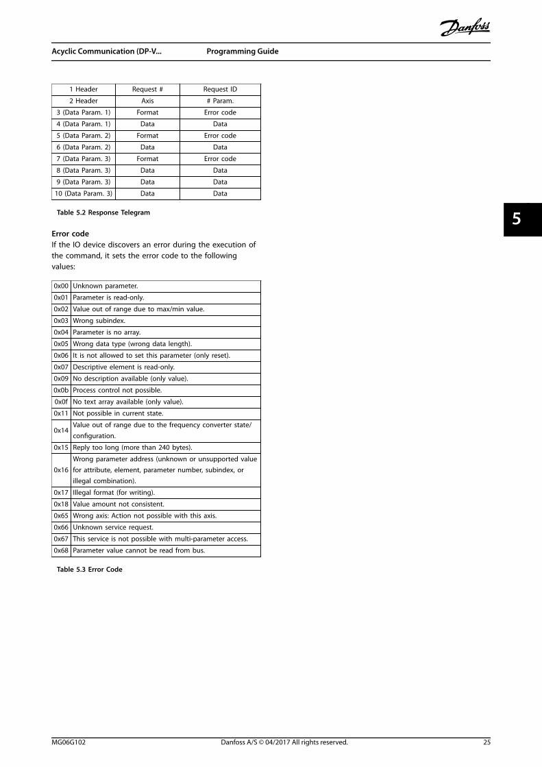
1 Header Request # Request ID
2 Header Axis # Param.
3 (Data Param. 1) Format Error code
4 (Data Param. 1) Data Data
5 (Data Param. 2) Format Error code
6 (Data Param. 2) Data Data
7 (Data Param. 3) Format Error code
8 (Data Param. 3) Data Data
9 (Data Param. 3) Data Data
10 (Data Param. 3) Data Data
Table 5.2 Response Telegram
Error codeIf the IO device discovers an error during the execution ofthe command, it sets the error code to the followingvalues:
0x00 Unknown parameter.
0x01 Parameter is read-only.
0x02 Value out of range due to max/min value.
0x03 Wrong subindex.
0x04 Parameter is no array.
0x05 Wrong data type (wrong data length).
0x06 It is not allowed to set this parameter (only reset).
0x07 Descriptive element is read-only.
0x09 No description available (only value).
0x0b Process control not possible.
0x0f No text array available (only value).
0x11 Not possible in current state.
0x14Value out of range due to the frequency converter state/configuration.
0x15 Reply too long (more than 240 bytes).
0x16Wrong parameter address (unknown or unsupported valuefor attribute, element, parameter number, subindex, orillegal combination).
0x17 Illegal format (for writing).
0x18 Value amount not consistent.
0x65 Wrong axis: Action not possible with this axis.
0x66 Unknown service request.
0x67 This service is not possible with multi-parameter access.
0x68 Parameter value cannot be read from bus.
Table 5.3 Error Code
Acyclic Communication (DP-V... Programming Guide
MG06G102 Danfoss A/S © 04/2017 All rights reserved. 25
5 5
6 Parameters
6.1 Parameter Group 0-** Operation/Display
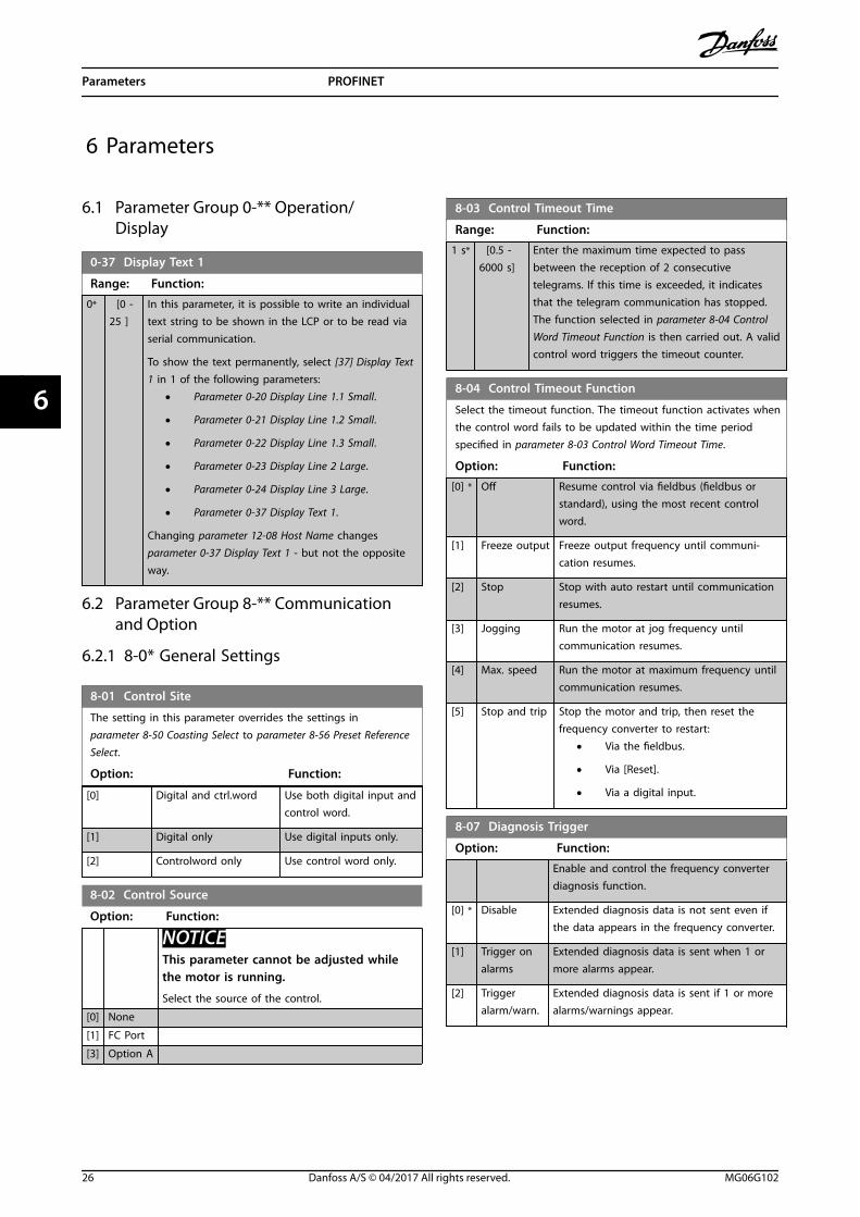
0-37 Display Text 1
Range: Function:
0* [0 -25 ]
In this parameter, it is possible to write an individualtext string to be shown in the LCP or to be read viaserial communication.
To show the text permanently, select [37] Display Text1 in 1 of the following parameters:
• Parameter 0-20 Display Line 1.1 Small.
• Parameter 0-21 Display Line 1.2 Small.
• Parameter 0-22 Display Line 1.3 Small.
• Parameter 0-23 Display Line 2 Large.
• Parameter 0-24 Display Line 3 Large.
• Parameter 0-37 Display Text 1.
Changing parameter 12-08 Host Name changes parameter 0-37 Display Text 1 - but not the oppositeway.
6.2 Parameter Group 8-** Communicationand Option
6.2.1 8-0* General Settings
8-01 Control Site
The setting in this parameter overrides the settings in parameter 8-50 Coasting Select to parameter 8-56 Preset ReferenceSelect.
Option: Function:
[0] Digital and ctrl.word Use both digital input andcontrol word.
[1] Digital only Use digital inputs only.
[2] Controlword only Use control word only.
8-02 Control Source
Option: Function:
NOTICEThis parameter cannot be adjusted whilethe motor is running.
Select the source of the control.
[0] None
[1] FC Port
[3] Option A
8-03 Control Timeout Time
Range: Function:
1 s* [0.5 -6000 s]
Enter the maximum time expected to passbetween the reception of 2 consecutivetelegrams. If this time is exceeded, it indicatesthat the telegram communication has stopped.The function selected in parameter 8-04 ControlWord Timeout Function is then carried out. A validcontrol word triggers the timeout counter.
8-04 Control Timeout Function
Select the timeout function. The timeout function activates whenthe control word fails to be updated within the time periodspecified in parameter 8-03 Control Word Timeout Time.
Option: Function:
[0] * Off Resume control via fieldbus (fieldbus orstandard), using the most recent controlword.
[1] Freeze output Freeze output frequency until communi-cation resumes.
[2] Stop Stop with auto restart until communicationresumes.
[3] Jogging Run the motor at jog frequency untilcommunication resumes.
[4] Max. speed Run the motor at maximum frequency untilcommunication resumes.
[5] Stop and trip Stop the motor and trip, then reset thefrequency converter to restart:
• Via the fieldbus.
• Via [Reset].
• Via a digital input.
8-07 Diagnosis Trigger
Option: Function:
Enable and control the frequency converterdiagnosis function.
[0] * Disable Extended diagnosis data is not sent even ifthe data appears in the frequency converter.
[1] Trigger onalarms
Extended diagnosis data is sent when 1 ormore alarms appear.
[2] Triggeralarm/warn.
Extended diagnosis data is sent if 1 or morealarms/warnings appear.
Parameters PROFINET
26 Danfoss A/S © 04/2017 All rights reserved. MG06G102
66
6.2.2 8-1* Ctrl. Word Settings
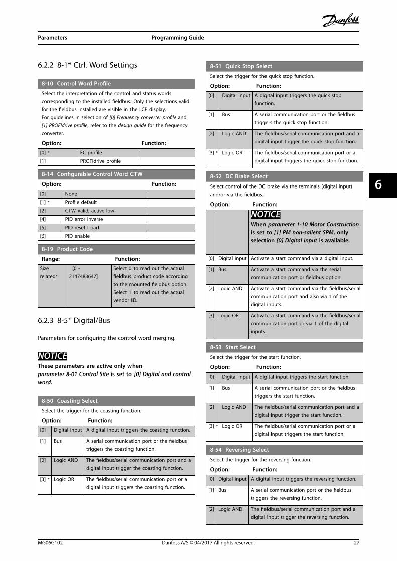
8-10 Control Word Profile
Select the interpretation of the control and status wordscorresponding to the installed fieldbus. Only the selections validfor the fieldbus installed are visible in the LCP display.For guidelines in selection of [0] Frequency converter profile and[1] PROFIdrive profile, refer to the design guide for the frequencyconverter.
Option: Function:
[0] * FC profile
[1] PROFIdrive profile
8-14 Configurable Control Word CTW
Option: Function:
[0] None
[1] * Profile default
[2] CTW Valid, active low
[4] PID error inverse
[5] PID reset I part
[6] PID enable
8-19 Product Code
Range: Function:
Sizerelated*
[0 -2147483647]
Select 0 to read out the actualfieldbus product code accordingto the mounted fieldbus option.Select 1 to read out the actualvendor ID.
6.2.3 8-5* Digital/Bus
Parameters for configuring the control word merging.
NOTICEThese parameters are active only when parameter 8-01 Control Site is set to [0] Digital and controlword.
8-50 Coasting Select
Select the trigger for the coasting function.
Option: Function:
[0] Digital input A digital input triggers the coasting function.
[1] Bus A serial communication port or the fieldbustriggers the coasting function.
[2] Logic AND The fieldbus/serial communication port and adigital input trigger the coasting function.
[3] * Logic OR The fieldbus/serial communication port or adigital input triggers the coasting function.
8-51 Quick Stop Select
Select the trigger for the quick stop function.
Option: Function:
[0] Digital input A digital input triggers the quick stopfunction.
[1] Bus A serial communication port or the fieldbustriggers the quick stop function.
[2] Logic AND The fieldbus/serial communication port and adigital input trigger the quick stop function.
[3] * Logic OR The fieldbus/serial communication port or adigital input triggers the quick stop function.
8-52 DC Brake Select
Select control of the DC brake via the terminals (digital input)and/or via the fieldbus.
Option: Function:
NOTICEWhen parameter 1-10 Motor Constructionis set to [1] PM non-salient SPM, onlyselection [0] Digital input is available.
[0] Digital input Activate a start command via a digital input.
[1] Bus Activate a start command via the serialcommunication port or fieldbus option.
[2] Logic AND Activate a start command via the fieldbus/serialcommunication port and also via 1 of thedigital inputs.
[3] Logic OR Activate a start command via the fieldbus/serialcommunication port or via 1 of the digitalinputs.
8-53 Start Select
Select the trigger for the start function.
Option: Function:
[0] Digital input A digital input triggers the start function.
[1] Bus A serial communication port or the fieldbustriggers the start function.
[2] Logic AND The fieldbus/serial communication port and adigital input trigger the start function.
[3] * Logic OR The fieldbus/serial communication port or adigital input triggers the start function.
8-54 Reversing Select
Select the trigger for the reversing function.
Option: Function:
[0] Digital input A digital input triggers the reversing function.
[1] Bus A serial communication port or the fieldbustriggers the reversing function.
[2] Logic AND The fieldbus/serial communication port and adigital input trigger the reversing function.
Parameters Programming Guide
MG06G102 Danfoss A/S © 04/2017 All rights reserved. 27
6 6

8-54 Reversing Select
Select the trigger for the reversing function.
Option: Function:
[3] Logic OR The fieldbus/serial communication port or adigital input triggers the reversing function.
8-55 Set-up Select
Select the trigger for the set-up selection.
Option: Function:
[0] Digital input A digital input triggers the set-up selection.
[1] Bus A serial communication port or the fieldbustriggers the set-up selection.
[2] Logic AND The fieldbus/serial communication port and adigital input trigger the set-up selection.
[3] * Logic OR The fieldbus/serial communication port or adigital input triggers the set-up selection.
8-56 Preset Reference Select
Option: Function:
Select the trigger for the preset referenceselection.
[0] Digitalinput
A digital input triggers the preset referenceselection.
[1] Bus A serial communication port or the fieldbustriggers the preset reference selection.
[2] Logic AND The fieldbus/serial communication port and adigital input trigger the preset referenceselection.
[3] * Logic OR The fieldbus/serial communication port or adigital input triggers the preset referenceselection.
8-57 Profidrive OFF2 Select
Option: Function:
[0] Digital input
[1] Bus
[2] Logic AND
[3] * Logic OR
8-58 Profidrive OFF3 Select
Option: Function:
[0] Digital input
[1] Bus
[2] Logic AND
[3] * Logic OR
6.2.4 8-9* Bus Feedback
Use the parameter group to configure the bus feedback.
8-90 Bus Jog 1 Speed
Range: Function:
100 RPM* [ 0 - 1500RPM]
Enter the jog speed. Activate thisfixed jog speed via the serial port orfieldbus option.
8-91 Bus Jog 2 Speed
Range: Function:
200 RPM* [ 0 - 1500RPM]
Enter the jog speed. Activate thisfixed jog speed via the serial port orfieldbus option.
6.3 Parameter Group 9-** PROFIdrive
9-07 Actual Value
Range: Function:
0* [0 - 65535 ] This parameter delivers the MAV for a MasterClass 2. This parameter is valid if the controlpriority is set to Master Class 2.
9-15 PCD Write Configuration
Array [10]
Option: Function:
Select the parameters to be assigned to PCD 3–10 ofthe telegrams. The number of available PCDs dependson the telegram type. The values in PCD 3–10 are thenwritten to the selected parameters as data values.Alternatively, specify a standard PROFIBUS telegram inparameter 9-22 Telegram Selection.
9-16 PCD Read Configuration
Array [10]
Option: Function:
Select the parameters to be assigned to PCD 3–10 ofthe telegrams. The number of available PCDs dependson the telegram type. PCDs 3–10 contain the actualdata values of the selected parameters. For standardPROFIBUS telegram, see parameter 9-22 TelegramSelection.
9-22 Telegram Selection
Option: Function:
This parameter shows the selectedstandard PROFIBUS telegram thatthe PROFINET IO controller has sentto the frequency converter. Atpower-up, or if a non-supportedtelegram is sent from the IOcontroller, this parameter showsNone in the display.
[1] Standard telegram1
Parameters PROFINET
28 Danfoss A/S © 04/2017 All rights reserved. MG06G102
66

9-22 Telegram Selection
Option: Function:
[100] * None
[101] PPO 1
[102] PPO 2
[103] PPO 3
[104] PPO 4
[105] PPO 5
[106] PPO 6
[107] PPO 7
[108] PPO 8
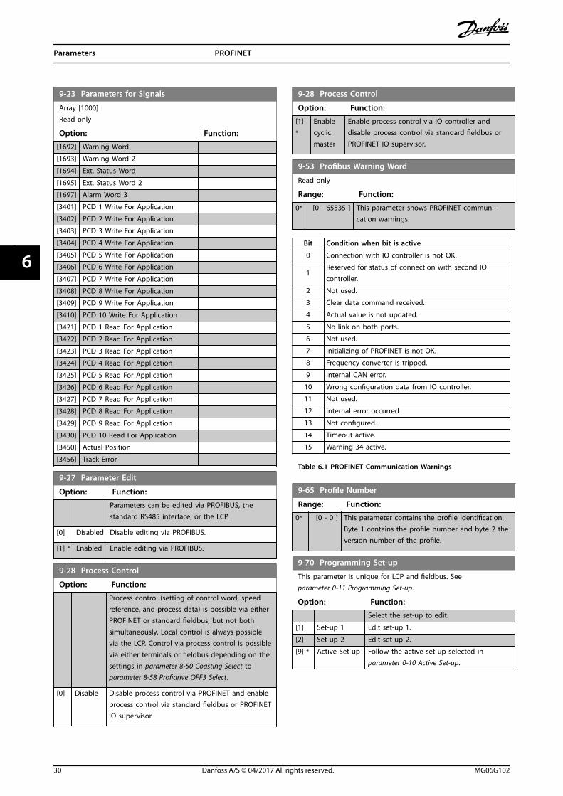
9-23 Parameters for Signals
Array [1000]Read only
Option: Function:
This parametercontains a list ofsignals available forselection inparameter 9-15 PCDWrite Configurationandparameter 9-16 PCDRead Configuration.
[0] * None
[302] Minimum Reference
[303] Maximum Reference
[311] Jog Speed [Hz]
[312] Catch up/slow Down Value
[341] Ramp 1 Ramp Up Time
[342] Ramp 1 Ramp Down Time
[351] Ramp 2 Ramp Up Time
[352] Ramp 2 Ramp Down Time
[380] Jog Ramp Time
[381] Quick Stop Ramp Time
[412] Motor Speed Low Limit [Hz]
[414] Motor Speed High Limit [Hz]
[416] Torque Limit Motor Mode
[417] Torque Limit Generator Mode
[553] Term. 29 High Ref./Feedb. Value
[558] Term. 33 High Ref./Feedb. Value
[590] Digital & Relay Bus Control
[593] Pulse Out 27 Bus Control
[595] Pulse Out 29 Bus Control
[615] Terminal 53 High Ref./Feedb. Value
[625] Terminal 54 High Ref./Feedb. Value
[676] Terminal 45 Output Bus Control
[696] Terminal 42 Output Bus Control
[733] Process PID Proportional Gain
[734] Process PID Integral Time
[735] Process PID Differentiation Time
[748] PCD Feed Forward
[890] Bus Jog 1 Speed
9-23 Parameters for Signals
Array [1000]Read only
Option: Function:
[891] Bus Jog 2 Speed
[1500] Operating hours
[1501] Running Hours
[1502] kWh Counter
[1600] Control Word
[1601] Reference [Unit]
[1602] Reference [%]
[1603] Status Word
[1605] Main Actual Value [%]
[1609] Custom Readout
[1610] Power [kW]
[1611] Power [hp]
[1612] Motor Voltage
[1613] Frequency
[1614] Motor current
[1615] Frequency [%]
[1616] Torque [Nm]
[1617] Speed [RPM]
[1618] Motor Thermal
[1622] Torque [%]
[1630] DC Link Voltage
[1633] Brake Energy /2 min
[1634] Heatsink Temp.
[1635] Inverter Thermal
[1638] SL Controller State
[1639] Control Card Temp.
[1650] External Reference
[1652] Feedback[Unit]
[1653] Digi Pot Reference
[1657] Feedback [RPM]
[1660] Digital Input
[1661] Terminal 53 Setting
[1662] Analog input 53
[1663] Terminal 54 Setting
[1664] Analog input 54
[1665] Analog output 42 [mA]
[1667] Pulse input 29 [Hz]
[1668] Pulse input 33 [Hz]
[1669] Pulse output 27 [Hz]
[1670] Pulse output 29 [Hz]
[1671] Relay output
[1672] Counter A
[1673] Counter B
[1679] Analog output 45 [mA]
[1680] Fieldbus CTW 1
[1682] Fieldbus REF 1
[1684] Comm. Option STW
[1685] FC Port CTW 1
[1690] Alarm Word
[1691] Alarm Word 2
Parameters Programming Guide
MG06G102 Danfoss A/S © 04/2017 All rights reserved. 29
6 6
9-23 Parameters for Signals
Array [1000]Read only
Option: Function:
[1692] Warning Word
[1693] Warning Word 2
[1694] Ext. Status Word
[1695] Ext. Status Word 2
[1697] Alarm Word 3
[3401] PCD 1 Write For Application
[3402] PCD 2 Write For Application
[3403] PCD 3 Write For Application
[3404] PCD 4 Write For Application
[3405] PCD 5 Write For Application
[3406] PCD 6 Write For Application
[3407] PCD 7 Write For Application
[3408] PCD 8 Write For Application
[3409] PCD 9 Write For Application
[3410] PCD 10 Write For Application
[3421] PCD 1 Read For Application
[3422] PCD 2 Read For Application
[3423] PCD 3 Read For Application
[3424] PCD 4 Read For Application
[3425] PCD 5 Read For Application
[3426] PCD 6 Read For Application
[3427] PCD 7 Read For Application
[3428] PCD 8 Read For Application
[3429] PCD 9 Read For Application
[3430] PCD 10 Read For Application
[3450] Actual Position
[3456] Track Error
9-27 Parameter Edit
Option: Function:
Parameters can be edited via PROFIBUS, thestandard RS485 interface, or the LCP.
[0] Disabled Disable editing via PROFIBUS.
[1] * Enabled Enable editing via PROFIBUS.
9-28 Process Control
Option: Function:
Process control (setting of control word, speedreference, and process data) is possible via eitherPROFINET or standard fieldbus, but not bothsimultaneously. Local control is always possiblevia the LCP. Control via process control is possiblevia either terminals or fieldbus depending on thesettings in parameter 8-50 Coasting Select to parameter 8-58 Profidrive OFF3 Select.
[0] Disable Disable process control via PROFINET and enableprocess control via standard fieldbus or PROFINETIO supervisor.
9-28 Process Control
Option: Function:
[1]*
Enablecyclicmaster
Enable process control via IO controller anddisable process control via standard fieldbus orPROFINET IO supervisor.
9-53 Profibus Warning Word
Read only
Range: Function:
0* [0 - 65535 ] This parameter shows PROFINET communi-cation warnings.
Bit Condition when bit is active
0 Connection with IO controller is not OK.
1Reserved for status of connection with second IOcontroller.
2 Not used.
3 Clear data command received.
4 Actual value is not updated.
5 No link on both ports.
6 Not used.
7 Initializing of PROFINET is not OK.
8 Frequency converter is tripped.
9 Internal CAN error.
10 Wrong configuration data from IO controller.
11 Not used.
12 Internal error occurred.
13 Not configured.
14 Timeout active.
15 Warning 34 active.
Table 6.1 PROFINET Communication Warnings
9-65 Profile Number
Range: Function:
0* [0 - 0 ] This parameter contains the profile identification.Byte 1 contains the profile number and byte 2 theversion number of the profile.
9-70 Programming Set-up
This parameter is unique for LCP and fieldbus. Seeparameter 0-11 Programming Set-up.
Option: Function:
Select the set-up to edit.
[1] Set-up 1 Edit set-up 1.
[2] Set-up 2 Edit set-up 2.
[9] * Active Set-up Follow the active set-up selected inparameter 0-10 Active Set-up.
Parameters PROFINET
30 Danfoss A/S © 04/2017 All rights reserved. MG06G102
66

9-71 Profibus Save Data Values
Option: Function:
Parameter values changed via PROFINET are notautomatically stored in the non-volatile memory.Use this parameter to activate a function thatstores parameter values in the EEPROM non-volatile memory, so changed parameter valuesare retained at power-down.
[0] * Off Deactivate the non-volatile storage function.
[1] Store allsetups
Store all parameter values for all set-ups in thenon-volatile memory. When all parameter valueshave been stored, the selection returns to [0]Off.
9-72 ProfibusDriveReset
Option: Function:
[0] * No action
[1] Power-onreset
Reset frequency converter upon power-up, asfor power cycle.
[3] Commoption reset
Reset the PROFINET option only, thePROFINET option goes through a power-upsequence.When reset, the frequency converterdisappears from the fieldbus, which maycause a communication error from themaster.
9-80 Defined Parameters (1)
Array [116]No LCP accessRead only
Range: Function:
0* [0 - 9999 ] This parameter shows a list of all the definedfrequency converter parameters available forPROFINET.
9-81 Defined Parameters (2)
Array [116]No LCP accessRead only
Range: Function:
0* [0 - 9999 ] This parameter shows a list of all the definedfrequency converter parameters available forPROFINET.
9-82 Defined Parameters (3)
Array [116]No LCP accessRead only
Range: Function:
0* [0 - 9999 ] This parameter shows a list of all the definedfrequency converter parameters available forPROFINET.
9-83 Defined Parameters (4)
Array [116]No LCP accessRead only
Range: Function:
0* [0 - 9999 ] This parameter shows a list of all the definedfrequency converter parameters available forPROFINET.
9-84 Defined Parameters (5)
Array [115]No LCP accessRead only
Range: Function:
0* [0 - 9999] This parameter shows a list of all the definedfrequency converter parameters available forPROFINET.
9-85 Defined Parameters (6)
Array [116]No LCP accessRead only
Range: Function:
0* [0 - 9999 ] This parameter shows a list of all the definedfrequency converter parameters available forPROFINET.
9-90 Changed Parameters (1)
Array [116]No LCP accessRead only
Range: Function:
0* [0 - 9999 ] This parameter shows a list of all the frequencyconverter parameters deviating from defaultsetting.
9-91 Changed Parameters (2)
Array [116]No LCP accessRead only
Range: Function:
0* [0 - 9999 ] This parameter shows a list of all the frequencyconverter parameters deviating from defaultsetting.
9-92 Changed Parameters (3)
Array [116]No LCP accessRead only
Range: Function:
0* [0 - 9999 ] This parameter shows a list of all the frequencyconverter parameters deviating from defaultsetting.
Parameters Programming Guide
MG06G102 Danfoss A/S © 04/2017 All rights reserved. 31
6 6

9-93 Changed Parameters (4)
Array [116]No LCP accessRead only
Range: Function:
0* [0 - 9999 ] This parameter shows a list of all the frequencyconverter parameters deviating from defaultsetting.
9-94 Changed Parameters (5)
Array [116]No LCP AddressRead only
Range: Function:
0* [0 - 9999 ] This parameter shows a list of all the frequencyconverter parameters deviating from defaultsetting.
6.4 Parameter Group 12-** Ethernet
6.4.1 12-0* IP Settings
12-01 IP Address
Range: Function:
0* [0 - 4294967295 ] Configure the IP address of the option.Read-only, if parameter 12-00 IP AddressAssignment is set to DHCP or BOOTP.
12-02 Subnet Mask
Range: Function:
0* [0 - 4294967295 ] Configure the IP subnet mask of theoption. Read-only, if parameter 12-00 IPAddress Assignment is set to DHCP orBOOTP.
12-03 Default Gateway
Range: Function:
0* [0 -4294967295 ]
Configure the IP default gateway of theoption. Read-only, if parameter 12-00 IPAddress Assignment is set to DHCP orBOOTP. In a non-routed network, thisaddress is set to the IP address of the I/Odevice.
12-04 DHCP Server
Range: Function:
0* [0 - 2147483647 ] Read-only. Show the IP address of thefound DHCP or BOOTP server.
12-05 Lease Expires
Range: Function:
Size related* [ 0 - 0] Read-only. Show the lease time left forthe current DHCP-assigned IP address.
12-06 Name Servers
Range: Function:
0* [0 - 4294967295 ] IP addresses of domain name servers.Can be automatically assigned whenusing DHCP.
12-07 Domain Name
Range: Function:
0 [0 - 48 ] Domain name of the attached network. Can beautomatically assigned when using DHCP network.
12-08 Host Name
Range: Function:
0* [0 - 48 ] Logical (given) name of option.
NOTICEThe display of the frequency converter onlyshows the first 19 characters, but theremaining characters are stored in thefrequency converter. If hardware switchesare different from all ON or all OFF, theswitches have priority.
12-09 Physical Address
Range: Function:
0* [0 - 17] Read-only. Shows the physical (MAC) address of theoption.
6.4.2 12-1* Ethernet Link Parameters
Apply to the whole parameter group.
Index [0] is used for port 1, and index [1] is used for port2.
12-10 Link Status
Read-only. Shows the link status of the Ethernet ports.
Option: Function:
[0] * No Link
[1] Link
12-11 Link Duration
Range: Function:
Size related* [ 0 - 0] Read-only. Shows the duration of thepresent link on each port in dd:hh:mm:ss.
12-12 Auto Negotiation
Option: Function:
Configure auto negotiation of Ethernet linkparameters, for each port: ON or OFF.
[0] Off Link Speed and Link Duplex can be configured inparameter 12-13 Link Speed and parameter 12-14 LinkDuplex.
Parameters PROFINET
32 Danfoss A/S © 04/2017 All rights reserved. MG06G102
66
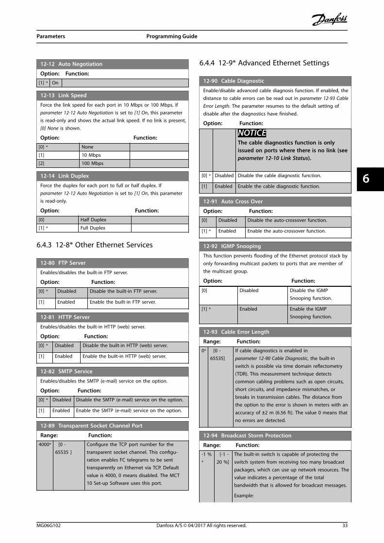
12-12 Auto Negotiation
Option: Function:
[1] * On
12-13 Link Speed
Force the link speed for each port in 10 Mbps or 100 Mbps. If parameter 12-12 Auto Negotiation is set to [1] On, this parameteris read-only and shows the actual link speed. If no link is present,[0] None is shown.
Option: Function:
[0] * None
[1] 10 Mbps
[2] 100 Mbps
12-14 Link Duplex
Force the duplex for each port to full or half duplex. Ifparameter 12-12 Auto Negotiation is set to [1] On, this parameteris read-only.
Option: Function:
[0] Half Duplex
[1] * Full Duplex
6.4.3 12-8* Other Ethernet Services
12-80 FTP Server
Enables/disables the built-in FTP server.
Option: Function:
[0] * Disabled Disable the built-in FTP server.
[1] Enabled Enable the built-in FTP server.
12-81 HTTP Server
Enables/disables the built-in HTTP (web) server.
Option: Function:
[0] * Disabled Disable the built-in HTTP (web) server.
[1] Enabled Enable the built-in HTTP (web) server.
12-82 SMTP Service
Enables/disables the SMTP (e-mail) service on the option.
Option: Function:
[0] * Disabled Disable the SMTP (e-mail) service on the option.
[1] Enabled Enable the SMTP (e-mail) service on the option.
12-89 Transparent Socket Channel Port
Range: Function:
4000* [0 -65535 ]
Configure the TCP port number for thetransparent socket channel. This configu-ration enables FC telegrams to be senttransparently on Ethernet via TCP. Defaultvalue is 4000, 0 means disabled. The MCT10 Set-up Software uses this port.
6.4.4 12-9* Advanced Ethernet Settings
12-90 Cable Diagnostic
Enable/disable advanced cable diagnosis function. If enabled, thedistance to cable errors can be read out in parameter 12-93 CableError Length. The parameter resumes to the default setting ofdisable after the diagnostics have finished.
Option: Function:
NOTICEThe cable diagnostics function is onlyissued on ports where there is no link (seeparameter 12-10 Link Status).
[0] * Disabled Disable the cable diagnostic function.
[1] Enabled Enable the cable diagnostic function.
12-91 Auto Cross Over
Option: Function:
[0] Disabled Disable the auto-crossover function.
[1] * Enabled Enable the auto-crossover function.
12-92 IGMP Snooping
This function prevents flooding of the Ethernet protocol stack byonly forwarding multicast packets to ports that are member ofthe multicast group.
Option: Function:
[0] Disabled Disable the IGMPSnooping function.
[1] * Enabled Enable the IGMPSnooping function.
12-93 Cable Error Length
Range: Function:
0* [0 -65535]
If cable diagnostics is enabled inparameter 12-90 Cable Diagnostic, the built-inswitch is possible via time domain reflectometry(TDR). This measurement technique detectscommon cabling problems such as open circuits,short circuits, and impedance mismatches, orbreaks in transmission cables. The distance fromthe option to the error is shown in meters with an
accuracy of ±2 m (6.56 ft). The value 0 means thatno errors are detected.
12-94 Broadcast Storm Protection
Range: Function:
-1 %*
[-1 -20 %]
The built-in switch is capable of protecting theswitch system from receiving too many broadcastpackages, which can use up network resources. Thevalue indicates a percentage of the totalbandwidth that is allowed for broadcast messages.
Example:
Parameters Programming Guide
MG06G102 Danfoss A/S © 04/2017 All rights reserved. 33
6 6
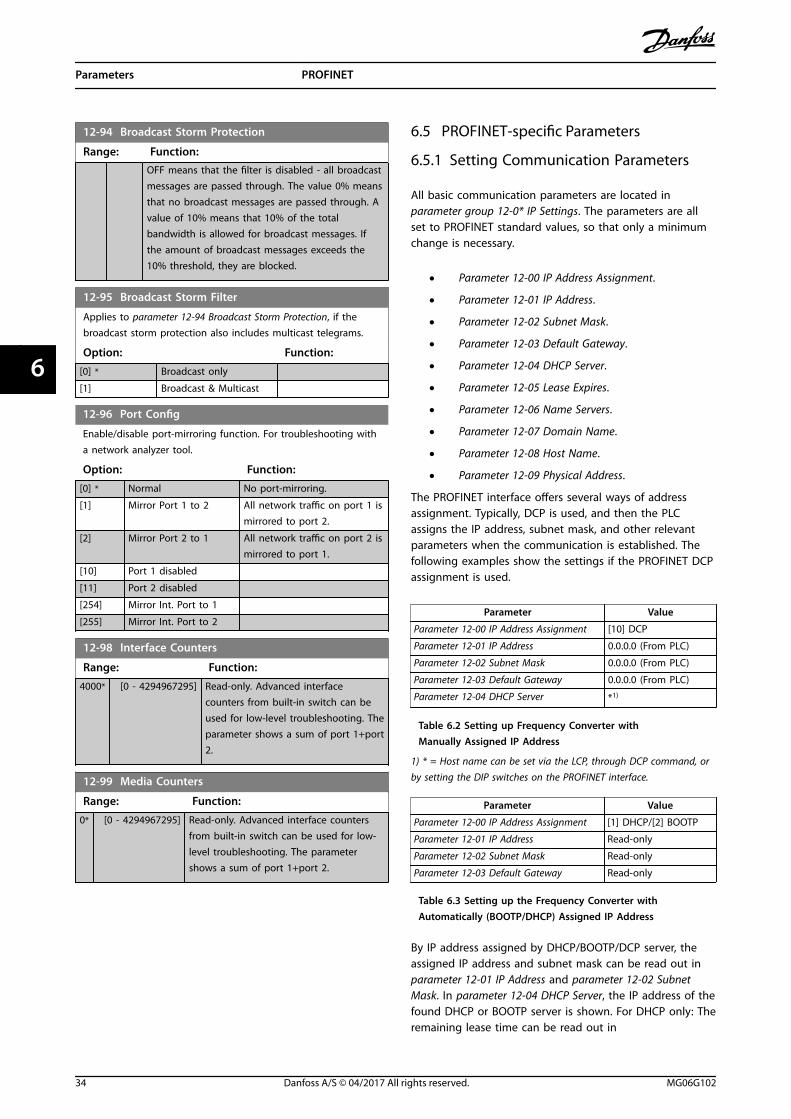
12-94 Broadcast Storm Protection
Range: Function:OFF means that the filter is disabled - all broadcastmessages are passed through. The value 0% meansthat no broadcast messages are passed through. Avalue of 10% means that 10% of the totalbandwidth is allowed for broadcast messages. Ifthe amount of broadcast messages exceeds the10% threshold, they are blocked.
12-95 Broadcast Storm Filter
Applies to parameter 12-94 Broadcast Storm Protection, if thebroadcast storm protection also includes multicast telegrams.
Option: Function:
[0] * Broadcast only
[1] Broadcast & Multicast
12-96 Port Config
Enable/disable port-mirroring function. For troubleshooting witha network analyzer tool.
Option: Function:
[0] * Normal No port-mirroring.
[1] Mirror Port 1 to 2 All network traffic on port 1 ismirrored to port 2.
[2] Mirror Port 2 to 1 All network traffic on port 2 ismirrored to port 1.
[10] Port 1 disabled
[11] Port 2 disabled
[254] Mirror Int. Port to 1
[255] Mirror Int. Port to 2
12-98 Interface Counters
Range: Function:
4000* [0 - 4294967295] Read-only. Advanced interfacecounters from built-in switch can beused for low-level troubleshooting. Theparameter shows a sum of port 1+port2.
12-99 Media Counters
Range: Function:
0* [0 - 4294967295] Read-only. Advanced interface countersfrom built-in switch can be used for low-level troubleshooting. The parametershows a sum of port 1+port 2.
6.5 PROFINET-specific Parameters
6.5.1 Setting Communication Parameters
All basic communication parameters are located inparameter group 12-0* IP Settings. The parameters are allset to PROFINET standard values, so that only a minimumchange is necessary.
• Parameter 12-00 IP Address Assignment.
• Parameter 12-01 IP Address.
• Parameter 12-02 Subnet Mask.
• Parameter 12-03 Default Gateway.
• Parameter 12-04 DHCP Server.
• Parameter 12-05 Lease Expires.
• Parameter 12-06 Name Servers.
• Parameter 12-07 Domain Name.
• Parameter 12-08 Host Name.
• Parameter 12-09 Physical Address.
The PROFINET interface offers several ways of addressassignment. Typically, DCP is used, and then the PLCassigns the IP address, subnet mask, and other relevantparameters when the communication is established. Thefollowing examples show the settings if the PROFINET DCPassignment is used.
Parameter Value
Parameter 12-00 IP Address Assignment [10] DCP
Parameter 12-01 IP Address 0.0.0.0 (From PLC)
Parameter 12-02 Subnet Mask 0.0.0.0 (From PLC)
Parameter 12-03 Default Gateway 0.0.0.0 (From PLC)
Parameter 12-04 DHCP Server *1)
Table 6.2 Setting up Frequency Converter withManually Assigned IP Address
1) * = Host name can be set via the LCP, through DCP command, orby setting the DIP switches on the PROFINET interface.
Parameter Value
Parameter 12-00 IP Address Assignment [1] DHCP/[2] BOOTP
Parameter 12-01 IP Address Read-only
Parameter 12-02 Subnet Mask Read-only
Parameter 12-03 Default Gateway Read-only
Table 6.3 Setting up the Frequency Converter withAutomatically (BOOTP/DHCP) Assigned IP Address
By IP address assigned by DHCP/BOOTP/DCP server, theassigned IP address and subnet mask can be read out inparameter 12-01 IP Address and parameter 12-02 SubnetMask. In parameter 12-04 DHCP Server, the IP address of thefound DHCP or BOOTP server is shown. For DHCP only: Theremaining lease time can be read out in
Parameters PROFINET
34 Danfoss A/S © 04/2017 All rights reserved. MG06G102
66
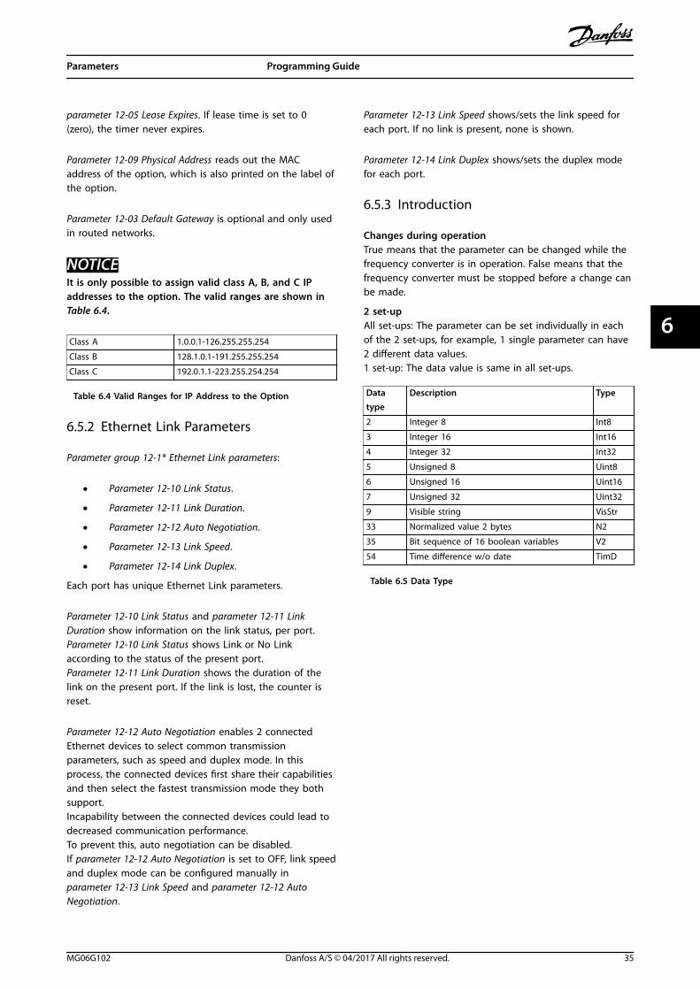
parameter 12-05 Lease Expires. If lease time is set to 0(zero), the timer never expires.
Parameter 12-09 Physical Address reads out the MACaddress of the option, which is also printed on the label ofthe option.
Parameter 12-03 Default Gateway is optional and only usedin routed networks.
NOTICEIt is only possible to assign valid class A, B, and C IPaddresses to the option. The valid ranges are shown inTable 6.4.
Class A 1.0.0.1-126.255.255.254
Class B 128.1.0.1-191.255.255.254
Class C 192.0.1.1-223.255.254.254
Table 6.4 Valid Ranges for IP Address to the Option
6.5.2 Ethernet Link Parameters
Parameter group 12-1* Ethernet Link parameters:
• Parameter 12-10 Link Status.
• Parameter 12-11 Link Duration.
• Parameter 12-12 Auto Negotiation.
• Parameter 12-13 Link Speed.
• Parameter 12-14 Link Duplex.
Each port has unique Ethernet Link parameters.
Parameter 12-10 Link Status and parameter 12-11 LinkDuration show information on the link status, per port.Parameter 12-10 Link Status shows Link or No Linkaccording to the status of the present port.Parameter 12-11 Link Duration shows the duration of thelink on the present port. If the link is lost, the counter isreset.
Parameter 12-12 Auto Negotiation enables 2 connectedEthernet devices to select common transmissionparameters, such as speed and duplex mode. In thisprocess, the connected devices first share their capabilitiesand then select the fastest transmission mode they bothsupport.Incapability between the connected devices could lead todecreased communication performance.To prevent this, auto negotiation can be disabled.If parameter 12-12 Auto Negotiation is set to OFF, link speedand duplex mode can be configured manually inparameter 12-13 Link Speed and parameter 12-12 AutoNegotiation.
Parameter 12-13 Link Speed shows/sets the link speed foreach port. If no link is present, none is shown.
Parameter 12-14 Link Duplex shows/sets the duplex modefor each port.
6.5.3 Introduction
Changes during operationTrue means that the parameter can be changed while thefrequency converter is in operation. False means that thefrequency converter must be stopped before a change canbe made.
2 set-upAll set-ups: The parameter can be set individually in eachof the 2 set-ups, for example, 1 single parameter can have2 different data values.1 set-up: The data value is same in all set-ups.
Datatype
Description Type
2 Integer 8 Int8
3 Integer 16 Int16
4 Integer 32 Int32
5 Unsigned 8 Uint8
6 Unsigned 16 Uint16
7 Unsigned 32 Uint32
9 Visible string VisStr
33 Normalized value 2 bytes N2
35 Bit sequence of 16 boolean variables V2
54 Time difference w/o date TimD
Table 6.5 Data Type
Parameters Programming Guide
MG06G102 Danfoss A/S © 04/2017 All rights reserved. 35
6 6
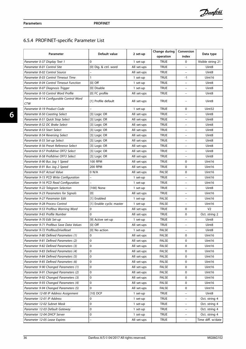
6.5.4 PROFINET-specific Parameter List
Parameter Default value 2 set-upChange during
operationConversion
indexData type
Parameter 0-37 Display Text 1 0 1 set-up TRUE 0 Visible string 21
Parameter 8-01 Control Site [0] Dig. & ctrl. word All set-ups TRUE – Uint8
Parameter 8-02 Control Source – All set-ups TRUE – Uint8
Parameter 8-03 Control Timeout Time 1 1 set-up TRUE -1 Uint16
Parameter 8-04 Control Timeout Function [0] Off 1 set-up TRUE – Uint8
Parameter 8-07 Diagnosis Trigger [0] Disable 1 set-up TRUE – Uint8
Parameter 8-10 Control Word Profile [0] FC profile All set-ups TRUE – Uint8
Parameter 8-14 Configurable Control WordCTW
[1] Profile default All set-ups TRUE – Uint8
Parameter 8-19 Product Code – 1 set-up TRUE 0 Uint32
Parameter 8-50 Coasting Select [3] Logic OR All set-ups TRUE – Uint8
Parameter 8-51 Quick Stop Select [3] Logic OR All set-ups TRUE – Uint8
Parameter 8-52 DC Brake Select [3] Logic OR All set-ups TRUE – Uint8
Parameter 8-53 Start Select [3] Logic OR All set-ups TRUE – Uint8
Parameter 8-54 Reversing Select [3] Logic OR All set-ups TRUE – Uint8
Parameter 8-55 Set-up Select [3] Logic OR All set-ups TRUE – Uint8
Parameter 8-56 Preset Reference Select [3] Logic OR All set-ups TRUE – Uint8
Parameter 8-57 Profidrive OFF2 Select [3] Logic OR All set-ups TRUE – Uint8
Parameter 8-58 Profidrive OFF3 Select [3] Logic OR All set-ups TRUE – Uint8
Parameter 8-90 Bus Jog 1 Speed 100 RPM All set-ups TRUE 0 Uint16
Parameter 8-91 Bus Jog 2 Speed 200 RPM All set-ups TRUE 0 Uint16
Parameter 9-07 Actual Value 0 N/A All set-ups FALSE 0 Uint16
Parameter 9-15 PCD Write Configuration – 1 set-up TRUE – Uint16
Parameter 9-16 PCD Read Configuration – 1 set-up TRUE – Uint16
Parameter 9-22 Telegram Selection [100] None 1 set-up TRUE – Uint8
Parameter 9-23 Parameters for Signals [0] All set-ups TRUE – Uint16
Parameter 9-27 Parameter Edit [1] Enabled 1 set-up FALSE – Uint16
Parameter 9-28 Process Control [1] Enable cyclic master 1 set-up FALSE – Uint16
Parameter 9-53 Profibus Warning Word 0 All set-ups TRUE 0 V2
Parameter 9-65 Profile Number 0 All set-ups TRUE 0 Oct. string 2
Parameter 9-70 Edit Set-up [9] Active set-up 1 set-up TRUE – Uint8
Parameter 9-71 Profibus Save Data Values [0] Off All set-ups TRUE – Uint8
Parameter 9-72 ProfibusDriveReset [0] No action 1 set-up FALSE – Uint8
Parameter 9-80 Defined Parameters (1) 0 All set-ups FALSE 0 Uint16
Parameter 9-81 Defined Parameters (2) 0 All set-ups FALSE 0 Uint16
Parameter 9-82 Defined Parameters (3) 0 All set-ups FALSE 0 Uint16
Parameter 9-83 Defined Parameters (4) 0 All set-ups FALSE 0 Uint16
Parameter 9-84 Defined Parameters (5) 0 All set-ups FALSE 0 Uint16
Parameter 9-85 Defined Parameters (6) 0 All set-ups FALSE 0 Uint16
Parameter 9-90 Changed Parameters (1) 0 All set-ups FALSE 0 Uint16
Parameter 9-91 Changed Parameters (2) 0 All set-ups FALSE 0 Uint16
Parameter 9-92 Changed Parameters (3) 0 All set-ups FALSE 0 Uint16
Parameter 9-93 Changed Parameters (4) 0 All set-ups FALSE 0 Uint16
Parameter 9-94 Changed Parameters (5) 0 All set-ups FALSE 0 Uint16
Parameter 12-00 IP Address Assignment [10] DCP 1 set-up TRUE – Uint8
Parameter 12-01 IP Address 0 1 set-up TRUE – Oct. string 4
Parameter 12-02 Subnet Mask 0 1 set-up TRUE – Oct. string 4
Parameter 12-03 Default Gateway 0 1 set-up TRUE – Oct. string 4
Parameter 12-04 DHCP Server 0 1 set-up TRUE – Oct. string 4
Parameter 12-05 Lease Expires – All set-ups TRUE – Time diff. w/date
Parameters PROFINET
36 Danfoss A/S © 04/2017 All rights reserved. MG06G102
66

Parameter Default value 2 set-upChange during
operationConversion
indexData type
Parameter 12-06 Name Servers 0 1 set-up TRUE – Oct. string 4
Parameter 12-07 Domain Name 0 1 set-up TRUE – Visible string 48
Parameter 12-08 Host Name 0 1 set-up TRUE – Visible string 48
Parameter 12-09 Physical Address 0 1 set-up TRUE – Visible string 17
Parameter 12-10 Link Status [0] No Link All set-ups TRUE – Uint8
Parameter 12-11 Link Duration – All set-ups TRUE – Time diff. w/date
Parameter 12-12 Auto Negotiation [1] On 1 set-up TRUE – Uint8
Parameter 12-13 Link Speed [0] None 1 set-up TRUE – Uint8
Parameter 12-14 Link Duplex [1] Full Duplex 1 set-up TRUE – Uint8
Parameter 12-80 FTP Server [0] Disabled 1 set-up TRUE – Uint8
Parameter 12-81 HTTP Server [0] Disabled 1 set-up TRUE – Uint8
Parameter 12-82 SMTP Service [0] Disabled 1 set-up TRUE – Uint8
Parameter 12-89 Transparent Socket ChannelPort
– 1 set-up TRUE 0 Uint16
Parameter 12-90 Cable Diagnostic [0] Disabled 1 set-up TRUE – Uint8
Parameter 12-91 Auto Cross Over [1] Enabled 1 set-up TRUE – Uint8
Parameter 12-92 IGMP Snooping [1] Enabled 1 set-up TRUE – Uint8
Parameter 12-93 Cable Error Length 0 1 set-up TRUE 0 Uint16
Parameter 12-94 Broadcast Storm Protection -1% 1 set-up TRUE 0 Int8
Parameter 12-95 Inactivity timeout [0] Broadcast only 1 set-up TRUE – Uint8
Parameter 12-96 Port Config – 1 set-up TRUE – Uint8
Parameter 12-98 Interface Counters 4000 All set-ups TRUE 0 Uint32
Parameter 12-99 Media Counters 0 All set-ups TRUE 0 Uint32
Table 6.6 PROFINET-specific Parameter List
6.5.5 Conversion
The various attributes of each parameter are shown infactory setting. Parameter values are transferred as wholenumbers only. Conversion factors are therefore used totransfer decimals.
A conversion factor of 0.1 means that the value transferredis multiplied by 0.1. The value 100 is therefore read as 10.0.
Examples:0 s ⇒ conversion index 00.00 s ⇒ conversion index -20 ms ⇒ conversion index -30.00 ms ⇒ conversion index -5
Conversion index Conversion factor
100 1
75 3600000
74 3600
70 60
67 1/60
6 1000000
5 100000
4 10000
3 1000
2 100
1 10
0 1
-1 0.1
-2 0.01
-3 0.001
-4 0.0001
-5 0.00001
-6 0.000001
Table 6.7 Conversion Table
Parameters Programming Guide
MG06G102 Danfoss A/S © 04/2017 All rights reserved. 37
6 6

6.6 Supported Object and Data Types
6.6.1 Parameter Description
PROFINET has a number of describing attributes.
6.6.2 Size Attribute
The size index and the conversion index for each parameter can be taken from the parameter list in the operating guide forthe frequency converter.
Physical unit Size index Measuring unit Designation Conversion index Conversion factor
0 No dimension
Time 4
second s 0 1-1 0.1-2 0.01
millisecond ms -3 0.001minute min 70 60hour h 74 3600day d 77 86400
Energy 8
watthour Wh 0 1kilowatthour kWh 3 1000
megawatthour MWh 6 106
Power 9
milliwatt mW -3 0.001watt W 0 1kilowatt kW 3 1000
megawatt MW 6 106
Rotation 11 rotation per minute RPM 67 1
Torque 16newtonmetre Nm 0 1kilonewtonmetre kNm 3 1000
Temperature 17 degree Celsius ºC 0 1
Voltage 21millivolt mV -3 0.001volt V 0 1kilovolt kV 3 1000
Current 22milliampere mA -3 0.001ampere A 0 1kiloampere kA 3 1000
Resistance 23milliohm mOhm -3 0.001ohm Ohm 0 1kiloohm kOhm 3 1000
Ratio 24 per cent % 0 1
Relative change 27 per cent % 0 1
Frequency 28
hertz Hz 0 1kilohertz kHz 3 1000
megahertz MHz 6 106
gigahertz GHz 9 109
Table 6.8 Size Index and Conversion Index
Parameters PROFINET
38 Danfoss A/S © 04/2017 All rights reserved. MG06G102
66

6.6.3 Supported Object and Data Types
Data type Short name Description Date type 2
3 I2 Integer 16 Int16
4 I4 Integer 32 Int32
5 – Unsigned 8 Uint8
6 O2 Unsigned 16 Uint16
7 O4 Unsigned 32 Uint32
9 – Visible string VisStr
10 – Byte string –
33 N2 Standardized value (16 bit) N2
35 V2 Bit sequence V2
54 – Time difference without date indication TimD
Table 6.9 Supported Data Types
Parameters Programming Guide
MG06G102 Danfoss A/S © 04/2017 All rights reserved. 39
6 6
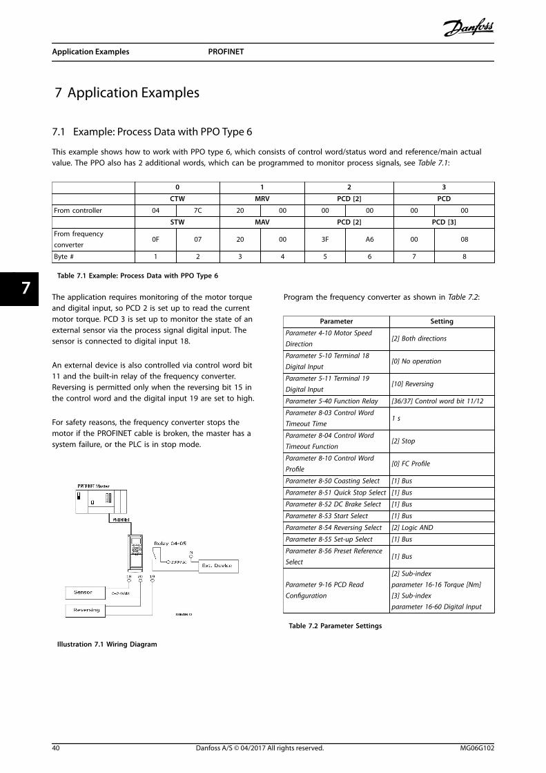
7 Application Examples
7.1 Example: Process Data with PPO Type 6
This example shows how to work with PPO type 6, which consists of control word/status word and reference/main actualvalue. The PPO also has 2 additional words, which can be programmed to monitor process signals, see Table 7.1:
0 1 2 3
CTW MRV PCD [2] PCD
From controller 04 7C 20 00 00 00 00 00
STW MAV PCD [2] PCD [3]
From frequencyconverter
0F 07 20 00 3F A6 00 08
Byte # 1 2 3 4 5 6 7 8
Table 7.1 Example: Process Data with PPO Type 6
The application requires monitoring of the motor torqueand digital input, so PCD 2 is set up to read the currentmotor torque. PCD 3 is set up to monitor the state of anexternal sensor via the process signal digital input. Thesensor is connected to digital input 18.
An external device is also controlled via control word bit11 and the built-in relay of the frequency converter.Reversing is permitted only when the reversing bit 15 inthe control word and the digital input 19 are set to high.
For safety reasons, the frequency converter stops themotor if the PROFINET cable is broken, the master has asystem failure, or the PLC is in stop mode.
Illustration 7.1 Wiring Diagram
Program the frequency converter as shown in Table 7.2:
Parameter Setting
Parameter 4-10 Motor SpeedDirection
[2] Both directions
Parameter 5-10 Terminal 18Digital Input
[0] No operation
Parameter 5-11 Terminal 19Digital Input
[10] Reversing
Parameter 5-40 Function Relay [36/37] Control word bit 11/12
Parameter 8-03 Control WordTimeout Time
1 s
Parameter 8-04 Control WordTimeout Function
[2] Stop
Parameter 8-10 Control WordProfile
[0] FC Profile
Parameter 8-50 Coasting Select [1] Bus
Parameter 8-51 Quick Stop Select [1] Bus
Parameter 8-52 DC Brake Select [1] Bus
Parameter 8-53 Start Select [1] Bus
Parameter 8-54 Reversing Select [2] Logic AND
Parameter 8-55 Set-up Select [1] Bus
Parameter 8-56 Preset ReferenceSelect
[1] Bus
Parameter 9-16 PCD ReadConfiguration
[2] Sub-indexparameter 16-16 Torque [Nm][3] Sub-indexparameter 16-60 Digital Input
Table 7.2 Parameter Settings
Application Examples PROFINET
40 Danfoss A/S © 04/2017 All rights reserved. MG06G102
77

7.2 Example: Control Word Telegram Using Standard Telegram 1/PPO3
This example shows how the control word telegram relates to the controller and the frequency converter, using FC controlprofile.
The control word telegram is sent from the PLC to the frequency converter. Standard telegram 1 is used in the example todemonstrate the full range of modules. All the values shown are arbitrary and are provided for demonstration purposesonly.
0 1 2 3
CTW MRV PCD PCD 04 7C 20 00
PQW: 256 258 260 262 CTW MRV
Bit no.: 31 30 29 28 27 26 25 24 23 22 21 20 19 18 17 16 15 14 13 12 11 10 9 8 7 6 5 4 3 2 1 0 0 0 0 0 0 1 0 0 0 1 1 1 1 1 0 0 0 0 1 0 0 0 0 0 0 0 0 0 0 0 0 0 0 4 7 C 2 0 0 0
Table 7.3 PCD
Table 7.3 indicates the bits contained within the control word and how they are presented as process data in standardtelegram 1 in this example.
Table 7.4 indicates which bit functions and which corresponding bit values are active in this example.
Bit Bit value = 0 Bit value = 1 Bit value
00 Reference value External selection lsb 0
C01 Reference value External selection msb 0
02 DC brake Ramp 1
03 Coasting Enable 1
04 Quick stop Ramp 1
705 Freeze output Ramp enable 1
06 Ramp stop Start 1
07 No function Reset 0
08 No function Jog 0
409 Ramp 1 Ramp 2 0
10 Data not valid Valid 1
11 No function Relay 01 active 0
12 No function Relay 02 active 0
013 Parameter set-up Selection lsb 0
14 Parameter set-up Selection msb 0
15 No function Reversing 0
Function active – – –
Function inactive – – –
Table 7.4 Control Word Telegram Using Standard Telegram 1/PPO3
Application Examples Programming Guide
MG06G102 Danfoss A/S © 04/2017 All rights reserved. 41
7 7

7.3 Example: Status Word Telegram Using Standard Telegram 1/PPO3
This example shows how the control word telegram relates to the PLC and the frequency converter, using FC control profile.
The control word telegram is sent from the frequency converter to the controller. Standard telegram 1 is used in theexample to demonstrate the full range of modules. All the values shown are arbitrary and are provided for demonstrationpurposes only.
0 1 2 3
STW MAV PCD PCD 0F 07 20 00
PIW: 256 258 260 262 STW MAV
Bit no.: 31 30 29 28 27 26 25 24 23 22 21 20 19 18 17 16 15 14 13 12 11 10 9 8 7 6 5 4 3 2 1 0 0 0 0 0 0 1 0 0 0 1 1 1 1 1 0 0 0 0 1 0 0 0 0 0 0 0 0 0 0 0 0 0 0 F 0 7 2 0 0 0
Table 7.5 PCD
Table 7.5 indicates the bits contained within the status word and how they are presented as process data in standardtelegram 1 in this example.
Table 7.6 indicates which bit functions and which corresponding bit values are active in this example.
Bit Bit value = 0 Bit value = 1 Bit value
00 Control not ready Control ready 1
701 Frequency converter not ready Frequency converter ready 1
02 Coasting Enable 1
03 No error Trip 0
04 No error Error (no trip) 0
005 Reserved – 0
06 No error Triplock 0
07 No warning Warning 0
08 Speed reference Speed ≠ reference 1
F09 Local operation Bus control 1
10 Outside frequency range Within frequency range 1
11 No operation In operation 1
12 Frequency converter OK Stopped, auto start 0
013 Voltage OK Voltage exceeded 0
14 Torque OK Torque exceeded 0
15 Timers OK Timers exceeded 0
Function active – – –
Function inactive – – –
Table 7.6 Status Word Telegram Using Standard Telegram 1/PPO3
Application Examples PROFINET
42 Danfoss A/S © 04/2017 All rights reserved. MG06G102
77

7.4 Example: PLC Programming
In this example, PPO type 6 is placed in the following input/output address:
130B
E940
.10
Inputaddress
256–257 258–259 260–261 262–263Outputaddress
256–257 258–259 260–261 262–263
Set-up Status word MAVMotortorque
Digitalinput
Set-upControl
wordReference Not used Not used
Illustration 7.2 PPO Type 6 Placed in the Input/Output Address
This network sends a start command (047C hex) and areference (2000 hex) of 50% to the frequency converter.
Illustration 7.3 Network Sends Start Command and Reference
This network reads the motor torque from the frequencyconverter. A new reference is sent to the frequencyconverter because the motor torque (86.0%) is higher thanthe compared value.
Illustration 7.4 Network Reads the Motor Torque
This network reads the status on the digital inputs fromthe frequency converter. If digital input 18 is ON, it stopsthe frequency converter.
Illustration 7.5 Network Reads the Status on the Digital Inputs
This network reverses the motor when digital input 19 isON, because parameter 8-54 Reversing Select isprogrammed to Logic AND.
Illustration 7.6 Network Reverses the Motor
This network activates relay 02.
130BA110.10 Illustration 7.7 Network Activates Relay 02
Application Examples Programming Guide
MG06G102 Danfoss A/S © 04/2017 All rights reserved. 43
7 7

7.5 Example: PLC and Network Monitoring
In automation systems the correct working of the I/Ocontroller (PLC) and network is of highest priority. ThePROFINET interface is designed so that it can monitor thesystem for the availability of the I/O controller and thenetwork.
The typical faults that the PROFINET interface can detectare:
• Power loss (I/O controller or networkcomponents).
• Cable faults (broken cable).
• Malfunction of networks components (partly).
• I/O controller program stopped execution.
The Danfoss FC series frequency converters have twoseparate functions to monitor and indicate communi-cations faults:
• Warning 34, activated by the fieldbus interface toindicate a fault on the fieldbus.
• Alarm 17, activated by the frequency converter ifthe frequency converter has not received acontrol word for a user specified time.
The PROFINET Interface suppresses the warning 34 for thefirst 60 s after power-up, this is to allow the I/O controller
to establish communication to the PROFINET interface andto avoid any sporadic faults while the networkinfrastructure is settling.
For monitoring communication from controllers (and thefieldbus interface) the frequency converter has a functionthat monitors the reception of I/O data to the controlword. The monitor feature has a timer that can be set to avalue from 0.5 s up to 6000 s (1.6 Hours). At power-up thetimer is disabled until it receives a valid control word(CTW).
When the timer is armed, the timer must be retriggeredwithin the time set in parameter 8-03 Control Timeout Time.Retriggering is done by receiving a new control word. If nocontrol word is received within this time, the frequencyconverter issues alarm 17, and execute one or morecommands:
• Set the motor into a well-defined state (forexample, stop, trip).
• Set digital outputs into a well-defined state (forexample, on, off, no change).
By this, the frequency converter reacts in a known way, ifcommunication faults occur.
Application Examples PROFINET
44 Danfoss A/S © 04/2017 All rights reserved. MG06G102
77
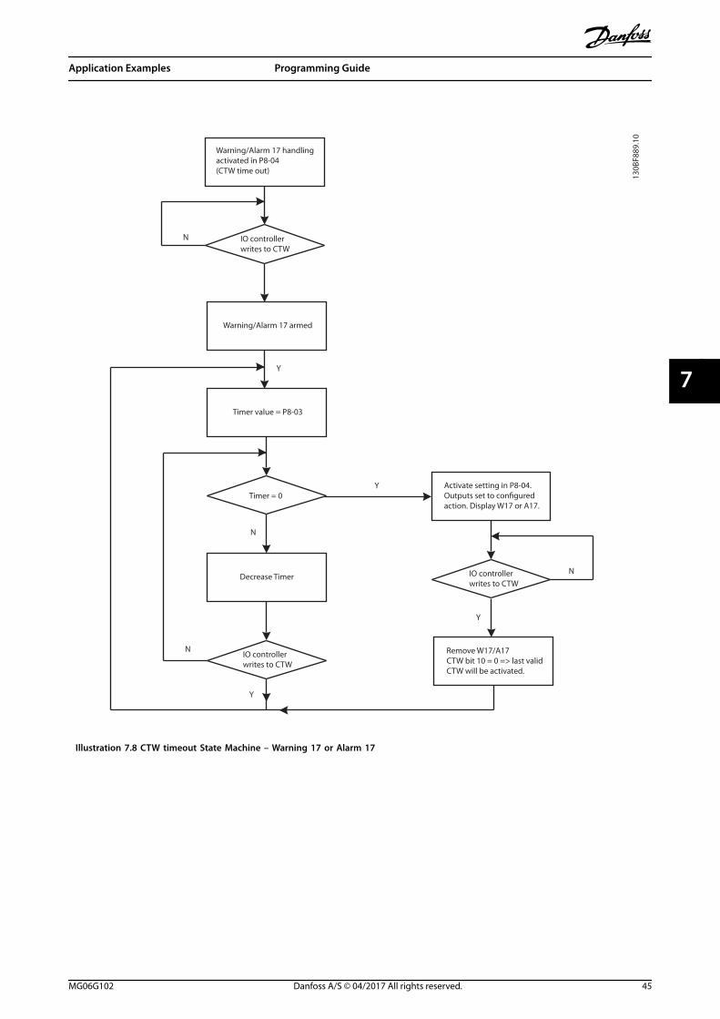
Warning/Alarm 17 handlingactivated in P8-04(CTW time out)
IO controllerwrites to CTW
Warning/Alarm 17 armed
Timer value = P8-03
Timer = 0
Decrease Timer
IO controllerwrites to CTW
Activate setting in P8-04.Outputs set to configuredaction. Display W17 or A17.
Remove W17/A17CTW bit 10 = 0 => last validCTW will be activated.
IO controllerwrites to CTW
N
Y
N
N
Y
Y
N
Y
130B
F889
.10
Illustration 7.8 CTW timeout State Machine – Warning 17 or Alarm 17
Application Examples Programming Guide
MG06G102 Danfoss A/S © 04/2017 All rights reserved. 45
7 7
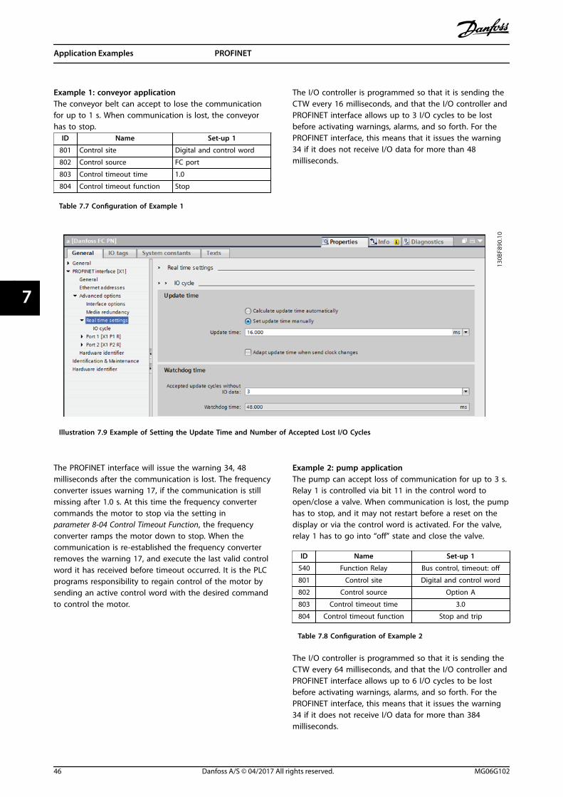
Example 1: conveyor applicationThe conveyor belt can accept to lose the communicationfor up to 1 s. When communication is lost, the conveyorhas to stop.
ID Name Set-up 1
801 Control site Digital and control word
802 Control source FC port
803 Control timeout time 1.0
804 Control timeout function Stop
Table 7.7 Configuration of Example 1
The I/O controller is programmed so that it is sending theCTW every 16 milliseconds, and that the I/O controller andPROFINET interface allows up to 3 I/O cycles to be lostbefore activating warnings, alarms, and so forth. For thePROFINET interface, this means that it issues the warning34 if it does not receive I/O data for more than 48milliseconds.
130B
F890
.10
Illustration 7.9 Example of Setting the Update Time and Number of Accepted Lost I/O Cycles
The PROFINET interface will issue the warning 34, 48milliseconds after the communication is lost. The frequencyconverter issues warning 17, if the communication is stillmissing after 1.0 s. At this time the frequency convertercommands the motor to stop via the setting inparameter 8-04 Control Timeout Function, the frequencyconverter ramps the motor down to stop. When thecommunication is re-established the frequency converterremoves the warning 17, and execute the last valid controlword it has received before timeout occurred. It is the PLCprograms responsibility to regain control of the motor bysending an active control word with the desired commandto control the motor.
Example 2: pump applicationThe pump can accept loss of communication for up to 3 s.Relay 1 is controlled via bit 11 in the control word toopen/close a valve. When communication is lost, the pumphas to stop, and it may not restart before a reset on thedisplay or via the control word is activated. For the valve,relay 1 has to go into “off” state and close the valve.
ID Name Set-up 1
540 Function Relay Bus control, timeout: off
801 Control site Digital and control word
802 Control source Option A
803 Control timeout time 3.0
804 Control timeout function Stop and trip
Table 7.8 Configuration of Example 2
The I/O controller is programmed so that it is sending theCTW every 64 milliseconds, and that the I/O controller andPROFINET interface allows up to 6 I/O cycles to be lostbefore activating warnings, alarms, and so forth. For thePROFINET interface, this means that it issues the warning34 if it does not receive I/O data for more than 384milliseconds.
Application Examples PROFINET
46 Danfoss A/S © 04/2017 All rights reserved. MG06G102
77
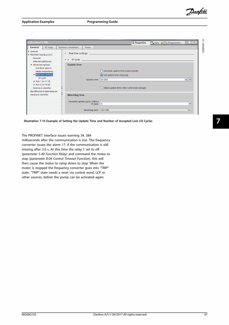
130B
F891
.10
Illustration 7.10 Example of Setting the Update Time and Number of Accepted Lost I/O Cycles
The PROFINET interface issues warning 34, 384milliseconds after the communication is lost. The frequencyconverter issues the alarm 17, if the communication is stillmissing after 3.0 s. At this time the relay 1 set to off(parameter 5-40 Function Relay) and command the motor tostop (parameter 8-04 Control Timeout Function), this willthen cause the motor to ramp down to stop. When themotor is stopped the frequency converter goes into “TRIP”state. “TRIP" state needs a reset via control word, LCP orother sources, before the pump can be activated again.
Application Examples Programming Guide
MG06G102 Danfoss A/S © 04/2017 All rights reserved. 47
7 7

8 Troubleshooting
8.1 No Response to Control Signals
Check 1: Is the control word valid?If bit 10 = 0 in the control word, the frequency converterdoes not accept the control word.
Check 2: Is the relationship between bits in the controlword and the terminal I/Os correct?Check the logical relationship in the frequency converter.
Define the desired logical relationship inparameter 8-50 Coasting Select to parameter 8-58 ProfidriveOFF3 Select according to the following range of options.Select the FC control mode, digital input and/or serialcommunication, using parameter 8-50 Coasting Select to parameter 8-58 Profidrive OFF3 Select.
If parameter 8-01 Control Site is set to digital only, thefrequency converter does not react to commands sent viathe control word.
Table 8.1 to Table 8.8 show a coast command's effect onthe frequency converter for the full range ofparameter 8-50 Coasting Select settings.
The effect of control mode on the function ofparameter 8-50 Coasting Select, parameter 8-51 Quick StopSelect, and parameter 8-52 DC Brake Select is as follows:
If [0] Digital input is selected, the terminals control thecoast and DC brake functions.
NOTICECoasting, quick stop, and DC brake functions are activefor logic 0.
Terminal Bits 02/03/04 Function
0 0 Coast/DC brake/Q-stop
0 1 Coast/DC brake/Q-stop
1 0 No coast/DC brake/Q-stop
1 1 No coast/DC brake/Q-stop
Table 8.1 [0] Digital Input
If [1] Serial communication is selected, commands areactivated only when given via serial communication.
Terminal Bits 02/03/04 Function
0 0 Coast/DC brake/Q-stop
0 1 No coast/DC brake/Q-stop
1 0 Coast/DC brake/Q-stop
1 1 No coast/DC brake/Q-stop
Table 8.2 [1] Serial Communication
If [2] Logic AND is selected, both signals must be activatedto perform the function.
Terminal Bits 02/03/04 Function
0 0 Coast/DC brake/Q-stop
0 1 No coast/DC brake/Q-stop
1 0 No coast/DC brake/Q-stop
1 1 No coast/DC brake/Q-stop
Table 8.3 [2] Logic AND
If [3] Logic OR is selected, activation of 1 signal activatesthe function.
Terminal Bits 02/03/04 Function
0 0 Coast/DC brake/Q-stop
0 1 Coast/DC brake/Q-stop
1 0 Coast/DC brake/Q-stop
1 1 No coast/DC brake/Q-stop
Table 8.4 [3] Logic OR
The effect of control mode on the function ofparameter 8-53 Start Select and parameter 8-54 ReversingSelect:
If [0] Digital input is selected, the terminals control the startand reversing functions.
Terminal Bits 06/15 Function
0 0 Stop/Counterclockwise
0 1 Stop/Counterclockwise
1 0 Start/Clockwise
1 1 Start/Clockwise
Table 8.5 [0] Digital input
If [1] Serial communication is selected, commands areactivated only when given via serial communication.
Terminal Bits 02/03/04 Function
0 0 Stop/Counterclockwise
0 1 Start/Clockwise
1 0 Stop/Counterclockwise
1 1 Start/Clockwise
Table 8.6 [1] Serial Communication
Troubleshooting PROFINET
48 Danfoss A/S © 04/2017 All rights reserved. MG06G102
88

If [2] Logic AND is selected, both signals must be activatedto perform the function.
Terminal Bits 02/03/04 Function
0 0 Stop/Counterclockwise
0 1 Stop/Counterclockwise
1 0 Stop/Counterclockwise
1 1 Start/Clockwise
Table 8.7 [2] Logic AND
If [3] Logic OR is selected, activation of 1 signal activatesthe function.
Terminal Bits 02/03/04 Function
0 0 Stop/Counterclockwise
0 1 Start/Clockwise
1 0 Start/Clockwise
1 1 Start/Clockwise
Table 8.8 [3] Logic OR
The effect of control mode on the function ofparameter 8-55 Set-up Select and parameter 8-56 PresetReference Select:
If [0] Digital input is selected, the terminals control the set-up and preset reference functions.
Terminal Bits 00/01, 13/14 Function
Msb Lsb Msb LsbPreset reference set-
up number
0 0 0 0 1
0 0 0 1 1
0 0 1 0 1
0 0 1 1 1
0 1 0 0 2
0 1 0 1 2
0 1 1 0 2
0 1 1 1 2
1 0 0 0 3
1 0 0 1 3
1 0 1 0 3
1 0 1 1 3
1 1 0 0 4
1 1 0 1 4
1 1 1 0 4
1 1 1 1 4
Table 8.9 [0] Digital Input
If [1] Serial communication is selected, commands areactivated only when given via serial communication.
Terminal Bits 00/01, 13/14 Function
Msb Lsb Msb LsbPreset reference set-
up number
0 0 0 0 1
0 0 0 1 2
0 0 1 0 3
0 0 1 1 4
0 1 0 0 1
0 1 0 1 2
0 1 1 0 3
0 1 1 1 4
1 0 0 0 1
1 0 0 1 2
1 0 1 0 3
1 0 1 1 4
1 1 0 0 1
1 1 0 1 2
1 1 1 0 3
1 1 1 1 4
Table 8.10 [1] Serial Communication
If [2] Logic AND is selected, both signals must be activatedto perform the function.
Terminal Bits 00/01, 13/14 Function
Msb Lsb Msb LsbPreset reference set-
up number
0 0 0 0 1
0 0 0 1 1
0 0 1 0 1
0 0 1 1 1
0 1 0 0 1
0 1 0 1 2
0 1 1 0 1
0 1 1 1 2
1 0 0 0 1
1 0 0 1 1
1 0 1 0 3
1 0 1 1 3
1 1 0 0 1
1 1 0 1 2
1 1 1 0 3
1 1 1 1 4
Table 8.11 [2] Logic AND
Troubleshooting Programming Guide
MG06G102 Danfoss A/S © 04/2017 All rights reserved. 49
8 8

If [3] Logic OR is selected, activation of 1 signal activatesthe function.
Terminal Bits 00/01, 13/14 Function
Msb Lsb Msb LsbPreset reference set-
up number
0 0 0 0 1
0 0 0 1 2
0 0 1 0 3
0 0 1 1 4
0 1 0 0 2
0 1 0 1 2
0 1 1 0 4
0 1 1 1 4
1 0 0 0 3
1 0 0 1 4
1 0 1 0 3
1 0 1 1 4
1 1 0 0 4
1 1 0 1 4
1 1 1 0 4
Table 8.12 [3] Logic OR
8.2 Warnings and Alarms
PROFINET alarm words and warning words are shown onthe display in hex format. If there is more than 1 warningor alarm, a sum of all warnings or alarms is shown. Alarmword, warning word, and PROFINET warning word can alsobe shown using the serial bus in parameter 16-90 AlarmWord, parameter 16-92 Warning Word, andparameter 9-53 Profibus Warning Word.
Bit (hex)Unit
diagnosebit
Alarm word(parameter 16-90 AlarmWord)
Alarmnumber
00000001 48 Brake check 28
00000002 49Power card overtem-perature
69
00000004 50 Earth fault 14
00000008 51Control card overtem-perature
65
00000010 52 Control word timeout 18
00000020 53 Overcurrent 13
00000040 54 Torque limit 12
00000080 55Motor thermistor overtem-perature
11
00000100 40Motor ETR overtem-perature
10
00000200 41 Inverter overloaded 9
00000400 42 DC-link undervoltage 8
00000800 43 DC-link overvoltage 7
00001000 44 Short circuit 16
00004000 46 Mains phase loss 4
00008000 47 AMA not OK 52
00010000 32 Live zero error 2
00020000 33 Internal fault 38
00040000 34 Brake overload 26
00080000 35 Motor phase U is missing 30
00100000 36 Motor phase V is missing 31
00200000 37 Motor phase W is missing 32
00400000 38 Fieldbus comm. fault 34
00800000 39 24 V supply fault 47
01000000 24 Mains failure 36
04000000 26 Brake resistor short circuit 25
08000000 27 Brake chopper fault 27
10000000 28 Option change 67
20000000 29Frequency converterinitialization
80
80000000 31 Mechanical brake low 63
Table 8.13 Parameter 16-90 Alarm Word
Troubleshooting PROFINET
50 Danfoss A/S © 04/2017 All rights reserved. MG06G102
88
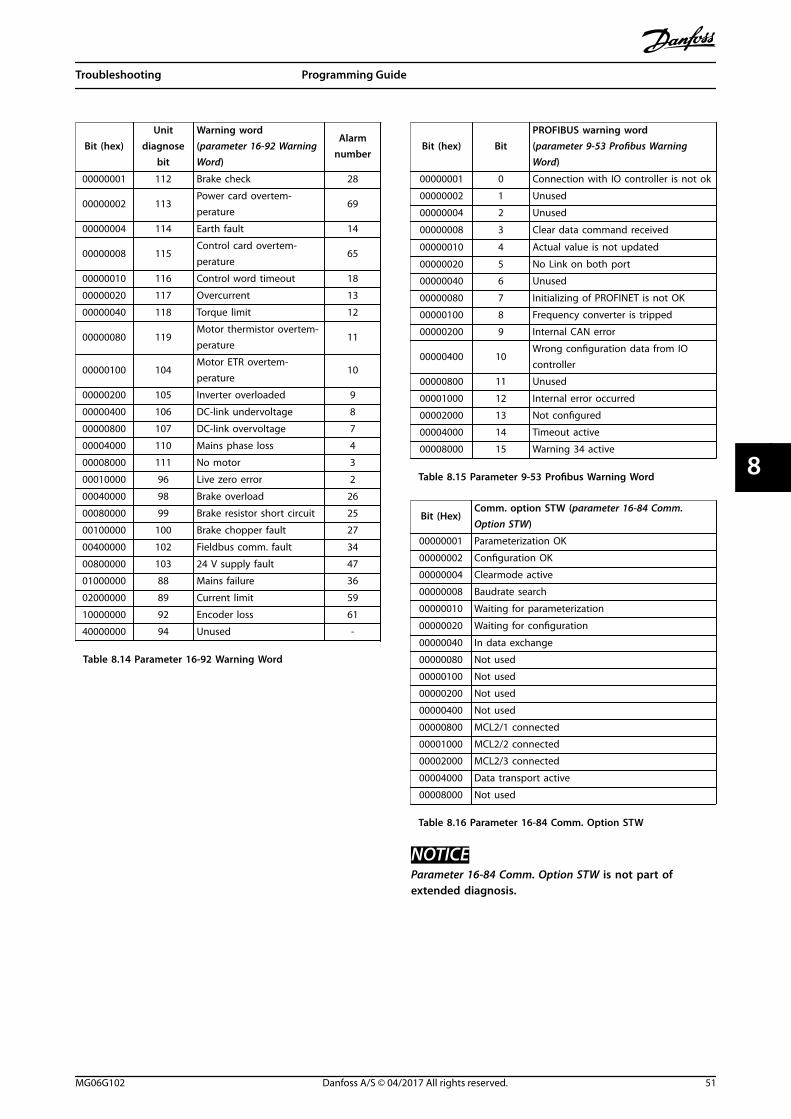
Bit (hex)Unit
diagnosebit
Warning word(parameter 16-92 WarningWord)
Alarmnumber
00000001 112 Brake check 28
00000002 113Power card overtem-perature
69
00000004 114 Earth fault 14
00000008 115Control card overtem-perature
65
00000010 116 Control word timeout 18
00000020 117 Overcurrent 13
00000040 118 Torque limit 12
00000080 119Motor thermistor overtem-perature
11
00000100 104Motor ETR overtem-perature
10
00000200 105 Inverter overloaded 9
00000400 106 DC-link undervoltage 8
00000800 107 DC-link overvoltage 7
00004000 110 Mains phase loss 4
00008000 111 No motor 3
00010000 96 Live zero error 2
00040000 98 Brake overload 26
00080000 99 Brake resistor short circuit 25
00100000 100 Brake chopper fault 27
00400000 102 Fieldbus comm. fault 34
00800000 103 24 V supply fault 47
01000000 88 Mains failure 36
02000000 89 Current limit 59
10000000 92 Encoder loss 61
40000000 94 Unused -
Table 8.14 Parameter 16-92 Warning Word
Bit (hex) BitPROFIBUS warning word(parameter 9-53 Profibus WarningWord)
00000001 0 Connection with IO controller is not ok
00000002 1 Unused
00000004 2 Unused
00000008 3 Clear data command received
00000010 4 Actual value is not updated
00000020 5 No Link on both port
00000040 6 Unused
00000080 7 Initializing of PROFINET is not OK
00000100 8 Frequency converter is tripped
00000200 9 Internal CAN error
00000400 10Wrong configuration data from IOcontroller
00000800 11 Unused
00001000 12 Internal error occurred
00002000 13 Not configured
00004000 14 Timeout active
00008000 15 Warning 34 active
Table 8.15 Parameter 9-53 Profibus Warning Word
Bit (Hex)Comm. option STW (parameter 16-84 Comm.Option STW)
00000001 Parameterization OK
00000002 Configuration OK
00000004 Clearmode active
00000008 Baudrate search
00000010 Waiting for parameterization
00000020 Waiting for configuration
00000040 In data exchange
00000080 Not used
00000100 Not used
00000200 Not used
00000400 Not used
00000800 MCL2/1 connected
00001000 MCL2/2 connected
00002000 MCL2/3 connected
00004000 Data transport active
00008000 Not used
Table 8.16 Parameter 16-84 Comm. Option STW
NOTICEParameter 16-84 Comm. Option STW is not part ofextended diagnosis.
Troubleshooting Programming Guide
MG06G102 Danfoss A/S © 04/2017 All rights reserved. 51
8 8
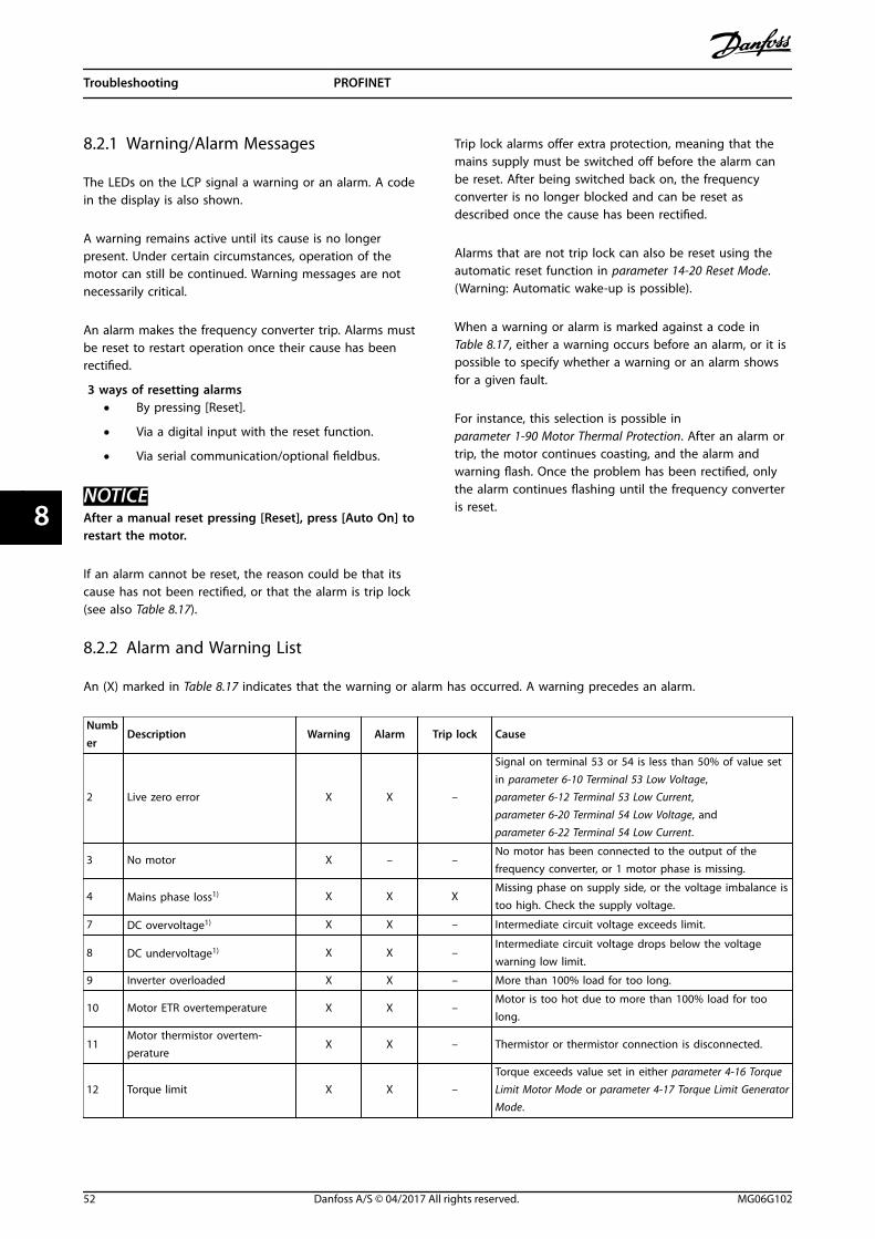
8.2.1 Warning/Alarm Messages
The LEDs on the LCP signal a warning or an alarm. A codein the display is also shown.
A warning remains active until its cause is no longerpresent. Under certain circumstances, operation of themotor can still be continued. Warning messages are notnecessarily critical.
An alarm makes the frequency converter trip. Alarms mustbe reset to restart operation once their cause has beenrectified.
3 ways of resetting alarms• By pressing [Reset].
• Via a digital input with the reset function.
• Via serial communication/optional fieldbus.
NOTICEAfter a manual reset pressing [Reset], press [Auto On] torestart the motor.
If an alarm cannot be reset, the reason could be that itscause has not been rectified, or that the alarm is trip lock(see also Table 8.17).
Trip lock alarms offer extra protection, meaning that themains supply must be switched off before the alarm canbe reset. After being switched back on, the frequencyconverter is no longer blocked and can be reset asdescribed once the cause has been rectified.
Alarms that are not trip lock can also be reset using theautomatic reset function in parameter 14-20 Reset Mode.(Warning: Automatic wake-up is possible).
When a warning or alarm is marked against a code in Table 8.17, either a warning occurs before an alarm, or it ispossible to specify whether a warning or an alarm showsfor a given fault.
For instance, this selection is possible inparameter 1-90 Motor Thermal Protection. After an alarm ortrip, the motor continues coasting, and the alarm andwarning flash. Once the problem has been rectified, onlythe alarm continues flashing until the frequency converteris reset.
8.2.2 Alarm and Warning List
An (X) marked in Table 8.17 indicates that the warning or alarm has occurred. A warning precedes an alarm.
Number
Description Warning Alarm Trip lock Cause
2 Live zero error X X –
Signal on terminal 53 or 54 is less than 50% of value setin parameter 6-10 Terminal 53 Low Voltage,parameter 6-12 Terminal 53 Low Current,parameter 6-20 Terminal 54 Low Voltage, andparameter 6-22 Terminal 54 Low Current.
3 No motor X – –No motor has been connected to the output of thefrequency converter, or 1 motor phase is missing.
4 Mains phase loss1) X X XMissing phase on supply side, or the voltage imbalance istoo high. Check the supply voltage.
7 DC overvoltage1) X X – Intermediate circuit voltage exceeds limit.
8 DC undervoltage1) X X –Intermediate circuit voltage drops below the voltagewarning low limit.
9 Inverter overloaded X X – More than 100% load for too long.
10 Motor ETR overtemperature X X –Motor is too hot due to more than 100% load for toolong.
11Motor thermistor overtem-perature
X X – Thermistor or thermistor connection is disconnected.
12 Torque limit X X –Torque exceeds value set in either parameter 4-16 TorqueLimit Motor Mode or parameter 4-17 Torque Limit GeneratorMode.
Troubleshooting PROFINET
52 Danfoss A/S © 04/2017 All rights reserved. MG06G102
88

Number
Description Warning Alarm Trip lock Cause
13 Overcurrent X X XInverter peak current limit is exceeded. For J1–J6 units, ifthis alarm occurs on power-up, check whether powercables are mistakenly connected to the motor terminals.
14 Earth fault – X X Discharge from output phases to ground.
16 Short circuit – X XShort circuit in motor or on motor terminals. For J7 units,if this alarm occurs on power-up, check whether powercables are mistakenly connected to the motor terminals.
17 Control word timeout X X – No communication to frequency converter.
18 Start failed – X – –
25 Brake resistor short-circuited – X XBrake resistor is short-circuited, thus the brake function isdisconnected.
26 Brake overload X X –The power transmitted to the brake resistor over the last120 s exceeds the limit. Possible corrections: Decreasebrake energy via lower speed or longer ramp time.
27Brake IGBT/Brake chopper short-circuited
– X XBrake transistor is short-circuited, thus brake function isdisconnected.
28 Brake check – X – Brake resistor is not connected/working.
30 U phase loss – X X Motor phase U is missing. Check the phase.
31 V phase loss – X X Motor phase V is missing. Check the phase.
32 W phase loss – X X Motor phase W is missing. Check the phase.
34 Fieldbus fault X X – PROFIBUS communication issues have occurred.
35 Option fault – X – Fieldbus or option B detects internal faults.
36 Mains failure X X –This warning/alarm is only active if the supply voltage tothe frequency converter is lost and parameter 14-10 MainsFailure is NOT set to [0] No Function.
38 Internal fault – X X Contact the local Danfoss supplier.
40 Overload T27 X – –Check the load connected to terminal 27 or removeshort-circuit connection.
41 Overload T29 X – –Check the load connected to terminal 29 or removeshort-circuit connection.
46 Gate drive voltage fault – X X –
47 24 V supply low X X X 24 V DC may be overloaded.
50 AMA calibration – X – –
51 AMA check Unom and Inom – X – Wrong setting for motor voltage and/or motor current.
52 AMA low Inom – X – Motor current is too low. Check the settings.
53 AMA big motor – X –The power size of the motor is too large for the AMA tooperate.
54 AMA small motor – X –The power size of the motor is too small for the AMA tooperate.
55 AMA parameter range – X –The parameter values of the motor are outside of theacceptable range. AMA does not run.
56 AMA interrupt – X – The AMA is interrupted.
57 AMA timeout – X – –
58 AMA internal – X – Contact Danfoss.
59 Current limit X X – Frequency converter overload.
60 External Interlock – X – –
61 Encoder loss X X – –
63 Mechanical brake low – X –Actual motor current has not exceeded release brakecurrent within start delay time window.
65 Control card temp X X XThe cutout temperature of the control card is 80 °C(176 °F).
69 Power card temp X X X –
Troubleshooting Programming Guide
MG06G102 Danfoss A/S © 04/2017 All rights reserved. 53
8 8
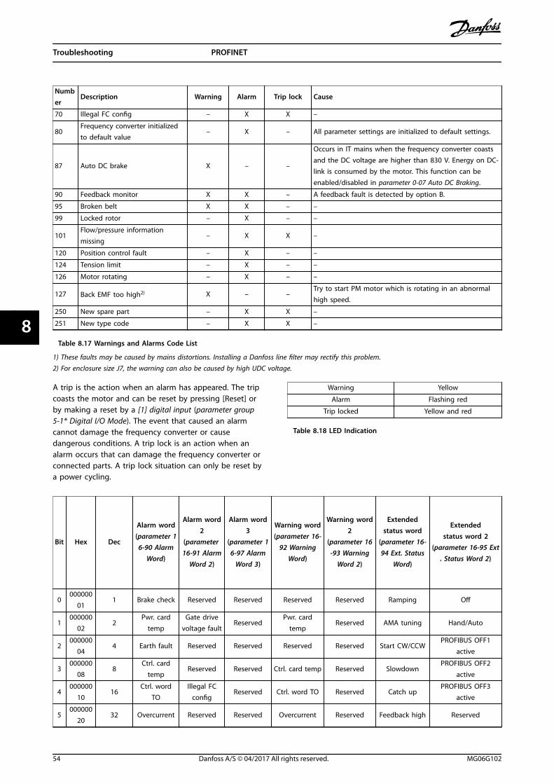
Number
Description Warning Alarm Trip lock Cause
70 Illegal FC config – X X –
80Frequency converter initializedto default value
– X – All parameter settings are initialized to default settings.
87 Auto DC brake X – –
Occurs in IT mains when the frequency converter coastsand the DC voltage are higher than 830 V. Energy on DC-link is consumed by the motor. This function can beenabled/disabled in parameter 0-07 Auto DC Braking.
90 Feedback monitor X X – A feedback fault is detected by option B.
95 Broken belt X X – –
99 Locked rotor – X – –
101Flow/pressure informationmissing
– X X –
120 Position control fault – X – –
124 Tension limit – X – –
126 Motor rotating – X – –
127 Back EMF too high2) X – –Try to start PM motor which is rotating in an abnormalhigh speed.
250 New spare part – X X –
251 New type code – X X –
Table 8.17 Warnings and Alarms Code List
1) These faults may be caused by mains distortions. Installing a Danfoss line filter may rectify this problem.2) For enclosure size J7, the warning can also be caused by high UDC voltage.
A trip is the action when an alarm has appeared. The tripcoasts the motor and can be reset by pressing [Reset] orby making a reset by a [1] digital input (parameter group5-1* Digital I/O Mode). The event that caused an alarmcannot damage the frequency converter or causedangerous conditions. A trip lock is an action when analarm occurs that can damage the frequency converter orconnected parts. A trip lock situation can only be reset bya power cycling.
Warning Yellow
Alarm Flashing red
Trip locked Yellow and red
Table 8.18 LED Indication
Bit Hex Dec
Alarm word(parameter 1
6-90 AlarmWord)
Alarm word2
(parameter 16-91 Alarm
Word 2)
Alarm word3
(parameter 16-97 Alarm
Word 3)
Warning word(parameter 16-
92 WarningWord)
Warning word2
(parameter 16-93 Warning
Word 2)
Extendedstatus word
(parameter 16-94 Ext. Status
Word)
Extendedstatus word 2
(parameter 16-95 Ext. Status Word 2)
0000000
011 Brake check Reserved Reserved Reserved Reserved Ramping Off
1000000
022
Pwr. cardtemp
Gate drivevoltage fault
ReservedPwr. card
tempReserved AMA tuning Hand/Auto
2000000
044 Earth fault Reserved Reserved Reserved Reserved Start CW/CCW
PROFIBUS OFF1active
3000000
088
Ctrl. cardtemp
Reserved Reserved Ctrl. card temp Reserved SlowdownPROFIBUS OFF2
active
4000000
1016
Ctrl. wordTO
Illegal FCconfig
Reserved Ctrl. word TO Reserved Catch upPROFIBUS OFF3
active
5000000
2032 Overcurrent Reserved Reserved Overcurrent Reserved Feedback high Reserved
Troubleshooting PROFINET
54 Danfoss A/S © 04/2017 All rights reserved. MG06G102
88

Bit Hex Dec
Alarm word(parameter 1
6-90 AlarmWord)
Alarm word2
(parameter 16-91 Alarm
Word 2)
Alarm word3
(parameter 16-97 Alarm
Word 3)
Warning word(parameter 16-
92 WarningWord)
Warning word2
(parameter 16-93 Warning
Word 2)
Extendedstatus word
(parameter 16-94 Ext. Status
Word)
Extendedstatus word 2
(parameter 16-95 Ext. Status Word 2)
6000000
4064 Torque limit Reserved Reserved Torque limit Reserved Feedback low Reserved
7000000
80128
Motor Th.over
Reserved Reserved Motor Th. over ReservedOutput current
highControl ready
8000001
00256
Motor ETRover
Broken belt ReservedMotor ETR
overBroken belt
Output currentlow
Frequency converterready
9000002
00512
Inverteroverld.
Reserved Reserved Inverter overld. ReservedOutput freq.
highQuick stop
10000004
001024
DCundervolt.
Start failed Reserved DC undervolt. ReservedOutput freq.
lowDC brake
11000008
002048 DC overvolt. Reserved Reserved DC overvolt. Reserved Brake check OK Stop
12000010
004096 Short circuit
Externalinterlock
Reserved Reserved Reserved Braking max Latched
13000020
008192 Reserved Reserved Reserved Reserved Reserved Braking Reserved
14000040
0016384
Mains ph.loss
Reserved Reserved Mains ph. loss Reserved Reserved Freeze output
15000080
0032768 AMA not OK Reserved Reserved No motor Auto DC brake OVC active Reserved
16000100
0065536
Live zeroerror
Reserved Reserved Live zero error Reserved AC brake Jog
17000200
00131072 Internal fault Reserved Reserved Reserved Reserved Reserved Reserved
18000400
00262144
Brakeoverload
Reserved ReservedBrake resistorpower limit
Reserved Reserved Start
19000800
00524288 U phase loss Reserved Reserved Reserved Reserved Reference high Reserved
20001000
001048576 V phase loss
Optiondetection
Reserved Reserved Overload T27 Reference low Start delay
21002000
002097152 W phase loss Option fault Reserved Reserved Reserved Reserved Sleep
22004000
004194304
Fieldbusfault
Locked rotor Reserved Fieldbus fault Reserved Reserved Sleep boost
23008000
008388608
24 V supplylow
Position ctrl.fault
Reserved24 V supply
lowReserved Reserved Running
24010000
0016777216 Mains failure
TensionLimit
Reserved Mains failure Reserved Reserved Bypass
25020000
0033554432 Reserved Current limit Reserved Current limit Reserved Reserved Reserved
26040000
0067108864
Brakeresistor
Reserved Reserved Reserved Reserved Reserved External interlock
27080000
0013421772
8Brake IGBT Reserved Reserved Reserved Reserved Reserved Reserved
28100000
0026843545
6Optionchange
Feedbackfault
Reserved Encoder loss Reserved Reserved FlyStart active
Troubleshooting Programming Guide
MG06G102 Danfoss A/S © 04/2017 All rights reserved. 55
8 8
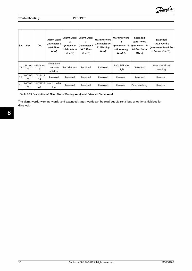
Bit Hex Dec
Alarm word(parameter 1
6-90 AlarmWord)
Alarm word2
(parameter 16-91 Alarm
Word 2)
Alarm word3
(parameter 16-97 Alarm
Word 3)
Warning word(parameter 16-
92 WarningWord)
Warning word2
(parameter 16-93 Warning
Word 2)
Extendedstatus word
(parameter 16-94 Ext. Status
Word)
Extendedstatus word 2
(parameter 16-95 Ext. Status Word 2)
29200000
0053687091
2
Frequencyconverterinitialized
Encoder loss Reserved ReservedBack EMF too
highReserved
Heat sink cleanwarning
30400000
0010737418
24Reserved Reserved Reserved Reserved Reserved Reserved Reserved
31800000
0021474836
48Mech. brake
lowReserved Reserved Reserved Reserved Database busy Reserved
Table 8.19 Description of Alarm Word, Warning Word, and Extended Status Word
The alarm words, warning words, and extended status words can be read out via serial bus or optional fieldbus fordiagnosis.
Troubleshooting PROFINET
56 Danfoss A/S © 04/2017 All rights reserved. MG06G102
88

Index
AAbbreviation............................................................................................. 4
Acyclic....................................................................................................... 21
Additional resources.............................................................................. 3
Alarm......................................................................................................... 52
Alarm word............................................................................................. 50
Approval and certification................................................................... 4
Approvals................................................................................................... 4
CCabling..................................................................................................... 33
Certifications............................................................................................. 4
Configuration........................................................................................... 4
Control profile........................................................................................ 13
Control word.......................................................................................... 14
Convention................................................................................................ 4
CTW........................................................................................................... 14
DData block............................................................................................... 24
Default settings..................................................................................... 35
Discharge time......................................................................................... 5
EEthernet..................................................................................... 32, 33, 35
FFC control mode
Digital input terminals................................................................... 13
GGeneral settings.................................................................................... 26
GSDML file................................................................................................. 7
HHigh voltage............................................................................................. 5
II/O................................................................................................................. 4
LLeakage current....................................................................................... 6
LED............................................................................................................... 4
Load sharing............................................................................................. 5
MMRV............................................................................................................ 11
NNo response to control signals........................................................ 48
PParameter......................................................................................... 34, 35
PCD............................................................................................................ 11
PPO types................................................................................................ 10
Process control data............................................................................ 11
Process control operation.................................................................. 13
Process data............................................................................................ 11
Process status data............................................................................... 12
PROFIdrive profile (CTW)................................................................... 14
PROFIdrive state transition diagram.............................................. 17
QQualified personnel................................................................................ 5
RReference................................................................................................... 4
Reference handling.............................................................................. 12
SSafety........................................................................................................... 6
Size attribute.......................................................................................... 38
Status word............................................................................................. 15
Supported data types......................................................................... 39
Symbol........................................................................................................ 4
UUnintended start..................................................................................... 5
VVLT parameter.......................................................................................... 9
WWarning.................................................................................................... 52
Warning and alarm list........................................................................ 54
Warning word........................................................................................ 50
Index Programming Guide
MG06G102 Danfoss A/S © 04/2017 All rights reserved. 57

Danfoss can accept no responsibility for possible errors in catalogues, brochures and other printed material. Danfoss reserves the right to alter its products without notice. This also applies toproducts already on order provided that such alterations can be made without subsequential changes being necessary in specifications already agreed. All trademarks in this material are propertyof the respective companies. Danfoss and the Danfoss logotype are trademarks of Danfoss A/S. All rights reserved.
Danfoss A/SUlsnaes 1DK-6300 Graastenvlt-drives.danfoss.com
*MG06G102*130R0704 MG06G102 04/2017