PROFIBUS Adapter Module...PROFIBUS-DP The NPBA-12 module supports the PROFIBUS-DP protocol,...
54
ABB Drives Installation and Start-up Guide PROFIBUS Adapter Module NPBA-12
Transcript of PROFIBUS Adapter Module...PROFIBUS-DP The NPBA-12 module supports the PROFIBUS-DP protocol,...

ABB Drives Installation andStart-up Guide
PROFIBUS Adapter ModuleNPBA-12


PROFIBUS Adapter ModuleNPBA-12
Installation andStart-up Guide
3BFE 64341588 R0125 REV B
EFFECTIVE: 06.10.2003
© 2003 ABB Oy. All Rights Reserved.

Safety Instructions
Overview This chapter states the safety instructions that must be followed when installing and operating the NPBA-12 PROFIBUS Adapter Module.The material in this chapter must be studied before attempting any work on, or with, the unit.
Warnings and Notes This manual distinguishes two sorts of safety instructions. Warnings are used to inform of conditions which can, if proper steps are not taken, lead to a serious fault condition, physical injury and death. Notes are used when the reader is required to pay special attention or when there is additional information available on the subject. Notes are less crucial than Warnings, but should not be disregarded.
Warnings Readers are informed of situations that can result in serious physical injury and/or serious damage to equipment with the following symbols:
Notes Readers are notified of the need for special attention or additional information available on the subject with the following symbols:
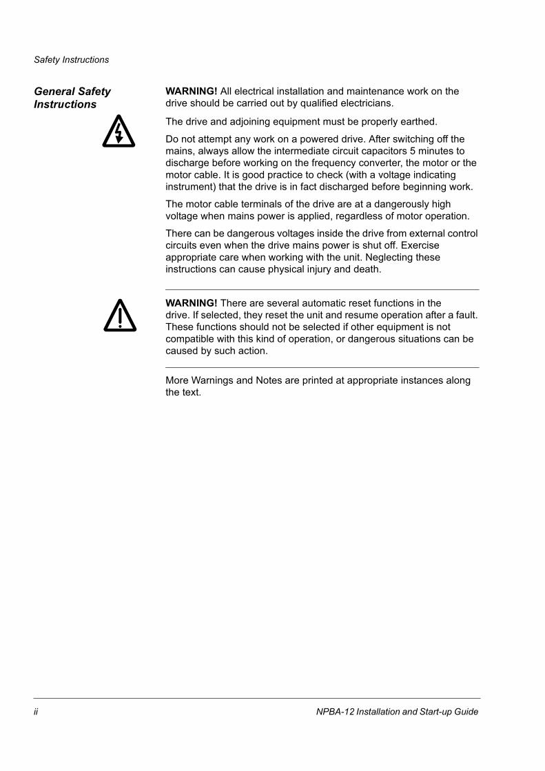
Dangerous Voltage Warning: warns of situations in which a high voltage can cause physical injury and/or damage equipment. The text next to this symbol describes ways to avoid the danger.
General Warning: warns of situations which can cause physical injury and/or damage equipment by means other than electrical. The text next to this symbol describes ways to avoid the danger.
Electrostatic Discharge Warning: warns of situations in which an electrostatic discharge can damage equipment. The text next to this symbol describes ways to avoid the danger.
CAUTION! Caution aims to draw special attention to a particular issue.
Note: Note gives additional information or points out more information available on the subject.
NPBA-12 Installation and Start-up Guide i
Safety Instructions
General Safety Instructions
WARNING! All electrical installation and maintenance work on the drive should be carried out by qualified electricians.
The drive and adjoining equipment must be properly earthed.
Do not attempt any work on a powered drive. After switching off the mains, always allow the intermediate circuit capacitors 5 minutes to discharge before working on the frequency converter, the motor or the motor cable. It is good practice to check (with a voltage indicating instrument) that the drive is in fact discharged before beginning work.
The motor cable terminals of the drive are at a dangerously high voltage when mains power is applied, regardless of motor operation.
There can be dangerous voltages inside the drive from external control circuits even when the drive mains power is shut off. Exercise appropriate care when working with the unit. Neglecting these instructions can cause physical injury and death.
WARNING! There are several automatic reset functions in thedrive. If selected, they reset the unit and resume operation after a fault. These functions should not be selected if other equipment is not compatible with this kind of operation, or dangerous situations can be caused by such action.
More Warnings and Notes are printed at appropriate instances along the text.
ii NPBA-12 Installation and Start-up Guide

Table of Contents
Safety InstructionsOverview . . . . . . . . . . . . . . . . . . . . . . . . . . . . . . . . . . . . . . . . . . . . . . . . . . . . . . . . . . . . . . . . . . . . . .1-iWarnings and Notes . . . . . . . . . . . . . . . . . . . . . . . . . . . . . . . . . . . . . . . . . . . . . . . . . . . . . . . . . . . . .1-iGeneral Safety Instructions. . . . . . . . . . . . . . . . . . . . . . . . . . . . . . . . . . . . . . . . . . . . . . . . . . . . . . . 1-ii
Table of Contents
Chapter 1 – Introduction to This GuideOverview . . . . . . . . . . . . . . . . . . . . . . . . . . . . . . . . . . . . . . . . . . . . . . . . . . . . . . . . . . . . . . . . . . . . . 1-1Intended Audience . . . . . . . . . . . . . . . . . . . . . . . . . . . . . . . . . . . . . . . . . . . . . . . . . . . . . . . . . . . . . 1-1What This Guide Contains . . . . . . . . . . . . . . . . . . . . . . . . . . . . . . . . . . . . . . . . . . . . . . . . . . . . . . . 1-1Conventions Used in This Guide. . . . . . . . . . . . . . . . . . . . . . . . . . . . . . . . . . . . . . . . . . . . . . . . . . . 1-2Further Information . . . . . . . . . . . . . . . . . . . . . . . . . . . . . . . . . . . . . . . . . . . . . . . . . . . . . . . . . . . . . 1-2
Chapter 2 – OverviewOverview . . . . . . . . . . . . . . . . . . . . . . . . . . . . . . . . . . . . . . . . . . . . . . . . . . . . . . . . . . . . . . . . . . . . . 2-1PROFIBUS . . . . . . . . . . . . . . . . . . . . . . . . . . . . . . . . . . . . . . . . . . . . . . . . . . . . . . . . . . . . . . . . . . . 2-1The NPBA-12 PROFIBUS Adapter Module . . . . . . . . . . . . . . . . . . . . . . . . . . . . . . . . . . . . . . . . . . 2-2
Compatibility . . . . . . . . . . . . . . . . . . . . . . . . . . . . . . . . . . . . . . . . . . . . . . . . . . . . . . . . . . . . . . . . 2-3Delivery Check . . . . . . . . . . . . . . . . . . . . . . . . . . . . . . . . . . . . . . . . . . . . . . . . . . . . . . . . . . . . . . 2-3Warranty and Liability Information . . . . . . . . . . . . . . . . . . . . . . . . . . . . . . . . . . . . . . . . . . . . . . . 2-3
Chapter 3 – Mechanical InstallationOverview . . . . . . . . . . . . . . . . . . . . . . . . . . . . . . . . . . . . . . . . . . . . . . . . . . . . . . . . . . . . . . . . . . . . . 3-1Mounting Outside the Drive. . . . . . . . . . . . . . . . . . . . . . . . . . . . . . . . . . . . . . . . . . . . . . . . . . . . . . . 3-1Mounting Inside the Drive . . . . . . . . . . . . . . . . . . . . . . . . . . . . . . . . . . . . . . . . . . . . . . . . . . . . . . . . 3-2
Chapter 4 – Electrical InstallationOverview . . . . . . . . . . . . . . . . . . . . . . . . . . . . . . . . . . . . . . . . . . . . . . . . . . . . . . . . . . . . . . . . . . . . . 4-1General Cabling Instructions. . . . . . . . . . . . . . . . . . . . . . . . . . . . . . . . . . . . . . . . . . . . . . . . . . . . . . 4-1Earthing the Module . . . . . . . . . . . . . . . . . . . . . . . . . . . . . . . . . . . . . . . . . . . . . . . . . . . . . . . . . . . . 4-1DIP Switch Settings. . . . . . . . . . . . . . . . . . . . . . . . . . . . . . . . . . . . . . . . . . . . . . . . . . . . . . . . . . . . . 4-2NPBA-12 Connections . . . . . . . . . . . . . . . . . . . . . . . . . . . . . . . . . . . . . . . . . . . . . . . . . . . . . . . . . . 4-3
Drive Connection . . . . . . . . . . . . . . . . . . . . . . . . . . . . . . . . . . . . . . . . . . . . . . . . . . . . . . . . . . . . 4-3PROFIBUS and Power Connections . . . . . . . . . . . . . . . . . . . . . . . . . . . . . . . . . . . . . . . . . . . . . 4-3
NPBA-12 Installation and Start-up Guide iii

Table of Contents
Chapter 5 – ProgrammingOverview . . . . . . . . . . . . . . . . . . . . . . . . . . . . . . . . . . . . . . . . . . . . . . . . . . . . . . . . . . . . . . . . . . . . 5-1Configuring the System . . . . . . . . . . . . . . . . . . . . . . . . . . . . . . . . . . . . . . . . . . . . . . . . . . . . . . . . . 5-1
PROFIBUS Connection Configuration. . . . . . . . . . . . . . . . . . . . . . . . . . . . . . . . . . . . . . . . . . . . 5-1Control Locations . . . . . . . . . . . . . . . . . . . . . . . . . . . . . . . . . . . . . . . . . . . . . . . . . . . . . . . . . . . . . . 5-5
Chapter 6 – CommunicationOverview . . . . . . . . . . . . . . . . . . . . . . . . . . . . . . . . . . . . . . . . . . . . . . . . . . . . . . . . . . . . . . . . . . . . 6-1PROFIBUS-DP. . . . . . . . . . . . . . . . . . . . . . . . . . . . . . . . . . . . . . . . . . . . . . . . . . . . . . . . . . . . . . . . 6-1
Service Access Points . . . . . . . . . . . . . . . . . . . . . . . . . . . . . . . . . . . . . . . . . . . . . . . . . . . . . . . . 6-1Communication Start-up . . . . . . . . . . . . . . . . . . . . . . . . . . . . . . . . . . . . . . . . . . . . . . . . . . . . . . 6-1
PPO Message Types . . . . . . . . . . . . . . . . . . . . . . . . . . . . . . . . . . . . . . . . . . . . . . . . . . . . . . . . . . . 6-5The Control Word and the Status Word. . . . . . . . . . . . . . . . . . . . . . . . . . . . . . . . . . . . . . . . . . . 6-6References . . . . . . . . . . . . . . . . . . . . . . . . . . . . . . . . . . . . . . . . . . . . . . . . . . . . . . . . . . . . . . . . 6-6Actual Values. . . . . . . . . . . . . . . . . . . . . . . . . . . . . . . . . . . . . . . . . . . . . . . . . . . . . . . . . . . . . . . 6-6
Parameters in Cyclic Communication (DP) . . . . . . . . . . . . . . . . . . . . . . . . . . . . . . . . . . . . . . . . . 6-10Parameters in Acyclic Communication (DPV1) . . . . . . . . . . . . . . . . . . . . . . . . . . . . . . . . . . . . . . 6-12
Chapter 7 – Fault TracingStatus LED Indications . . . . . . . . . . . . . . . . . . . . . . . . . . . . . . . . . . . . . . . . . . . . . . . . . . . . . . . . . . 7-1
Appendix A – PROFIBUS Parameters
Appendix B – Definitions and AbbreviationsPROFIBUS Definitions . . . . . . . . . . . . . . . . . . . . . . . . . . . . . . . . . . . . . . . . . . . . . . . . . . . . . . . . . . B-1PROFIBUS Abbreviations . . . . . . . . . . . . . . . . . . . . . . . . . . . . . . . . . . . . . . . . . . . . . . . . . . . . . . . B-3
Appendix C – Technical DataDDCS Link . . . . . . . . . . . . . . . . . . . . . . . . . . . . . . . . . . . . . . . . . . . . . . . . . . . . . . . . . . . . . . . . . . . C-1Fieldbus Link . . . . . . . . . . . . . . . . . . . . . . . . . . . . . . . . . . . . . . . . . . . . . . . . . . . . . . . . . . . . . . . . . C-2NPBA-12 . . . . . . . . . . . . . . . . . . . . . . . . . . . . . . . . . . . . . . . . . . . . . . . . . . . . . . . . . . . . . . . . . . . . C-3
Appendix D – Ambient ConditionsAmbient Conditions, Operation . . . . . . . . . . . . . . . . . . . . . . . . . . . . . . . . . . . . . . . . . . . . . . . . . . . D-1Ambient Conditions, Storage . . . . . . . . . . . . . . . . . . . . . . . . . . . . . . . . . . . . . . . . . . . . . . . . . . . . . D-1Ambient Conditions, Transportation . . . . . . . . . . . . . . . . . . . . . . . . . . . . . . . . . . . . . . . . . . . . . . . . D-1
iv NPBA-12 Installation and Start-up Guide
Chapter 1 – Introduction to This Guide
Overview This chapter contains a description of the Installation and Start-up Guide for the NPBA-12 PROFIBUS Adapter Module.
Intended Audience The Guide is intended for the people who are responsible for installing, commissioning and using a PROFIBUS Adapter Module with an ABB drive. The reader is expected to have a basic knowledge of electrical fundamentals, electrical wiring practices, the drive, the use of the drive control panel, and the PROFIBUS protocol family.
What This Guide Contains
The installation and start-up of the NPBA-12 PROFIBUS Adapter Module are introduced in this Guide.
It is assumed that the drive is installed and ready to operate before starting the installation of the adapter module. For more information on the installation and start-up procedures of the drive, please refer to its user documentation.
Safety Instructions are featured in the first few pages of this Guide. Safety Instructions describe the formats for various warnings and notations used within this Guide. This chapter also states the safety instructions which apply to the installation and operation of theNPBA-12 Module.
Chapter 1 – Introduction to This Guide contains a short description of the Guide.
Chapter 2 – Overview contains a short description of the PROFIBUS protocol and the NPBA-12 PROFIBUS Adapter Module, a delivery checklist, and information on the manufacturer’s warranty.
Chapter 3 – Mechanical Installation contains placing and mounting instructions for the module.
Chapter 4 – Electrical Installation contains wiring, bus termination and earthing instructions.
Chapter 5 – Programming explains how to program the master station and the drive before the communication through the adapter module can be started.
Chapter 6 – Communication contains a description of how data is transmitted through the NPBA-12 Module.
Chapter 7 – Fault Tracing explains how to trace faults with the Status LEDs on the NPBA-12 Module.
NPBA-12 Installation and Start-up Guide 1-1

Chapter 1 – Introduction to This Guide
Appendix A presents the PROFIBUS Profile-specific parameters.
Appendix B explains definitions and abbreviations concerning the PROFIBUS protocol family.
Appendix C contains Technical Data.
Appendix D contains a specification of the ambient conditions allowed during transportation, storage and use of the NPBA-12.
Conventions Used in This Guide
Communication Module Communication Module is a parameter name/parameter selection name for a device (e.g. a fieldbus adapter) through which the drive is connected to an external serial communication network (e.g. a fieldbus). The communication with the communication module is activated with a drive parameter.
Data Sets andData Words
Data sets are clusters of data sent through the DDCS link between the NPBA-12 Adapter Module and the drive. Each data set consists of three 16-bit words, ie. data words. The Control Word (sometimes called the Command Word) and the Status Word, References and Actual Values (see Chapter 6) are types of data words; the contents of some data words are user-definable.
NPBA-12 PROFIBUSAdapter Module
The NPBA-12 Adapter Module is one of the optional fieldbus adapter modules available for ABB drives. The NPBA-12 is a device through which an ABB drive is connected to a PROFIBUS serial communication bus.
Parameter A parameter is an operating instruction for the drive. Parameters can be read and programmed with the drive control panel, or through the NPBA-12 Module.
Further Information Further information is available on the World Wide Web from www.profibus.com.
1-2 NPBA-12 Installation and Start-up Guide

Chapter 2 – Overview
Overview This chapter contains a short description of the PROFIBUS standard and the NPBA-12 Adapter Module, a delivery checklist, and warranty information.
PROFIBUS PROFIBUS is an open serial communication standard that enables data exchange between all kinds of automation components. There are three main variations of PROFIBUS: PROFIBUS-FMS (Fieldbus Message Specification), PROFIBUS-DP (Decentralised Periphery) and PROFIBUS-PA (Process Automation). The NPBA-12 PROFIBUS Adapter Module supports the PROFIBUS-DP and PROFIBUS-DPV1 protocols.
The physical transmission medium of the bus is a twisted pair cable (according to the RS-485 standard). The maximum length of the bus cable is 100 to 1200 metres, depending on the selected transmission rate (see Appendix C). Up to 31 stations can be connected to the same PROFIBUS system without the use of repeaters. With repeaters, it is possible to connect 127 stations (including the repeaters, and the master station) to the system.
In PROFIBUS communication, the master station – usually a programmable logic controller (PLC) – polls the slaves which respond and take the actions requested by the master. It is also possible to send a command to several slaves at the same time; in this case the slaves send no response message to the master. Communication between the slaves is not possible on a PROFIBUS link.
The PROFIBUS protocol family is specified in the EN 50170 Standard. The communication with a drive is discussed in PROFIDRIVE-PROFILE – The PROFIBUS Profile for Adjustable Speed Drives. For further information on PROFIBUS, refer to the above-mentioned standards.
NPBA-12 Installation and Start-up Guide 2-1
Chapter 2 – Overview
The NPBA-12 PROFIBUS Adapter Module
The NPBA-12 PROFIBUS Adapter Module is an optional device forABB drives which enables the connection of the drive to a PROFIBUS system. The drive is considered as a slave in the PROFIBUS network. Through the NPBA-12 PROFIBUS Adapter Module it is possible to:
• Give control commands to the drive(Start, Stop, Run enable, etc.)
• Feed a motor speed or torque reference to the drive
• Give a process actual value or a process reference to thePID controller of the drive
• Read status information and actual values from the drive
• Change drive parameter values
• Reset a drive fault.
The PROFIBUS commands and services supported by the NPBA-12 PROFIBUS Adapter Module are discussed in Chapter 6. Please refer to the user documentation of the drive as to which commands are supported by the drive.
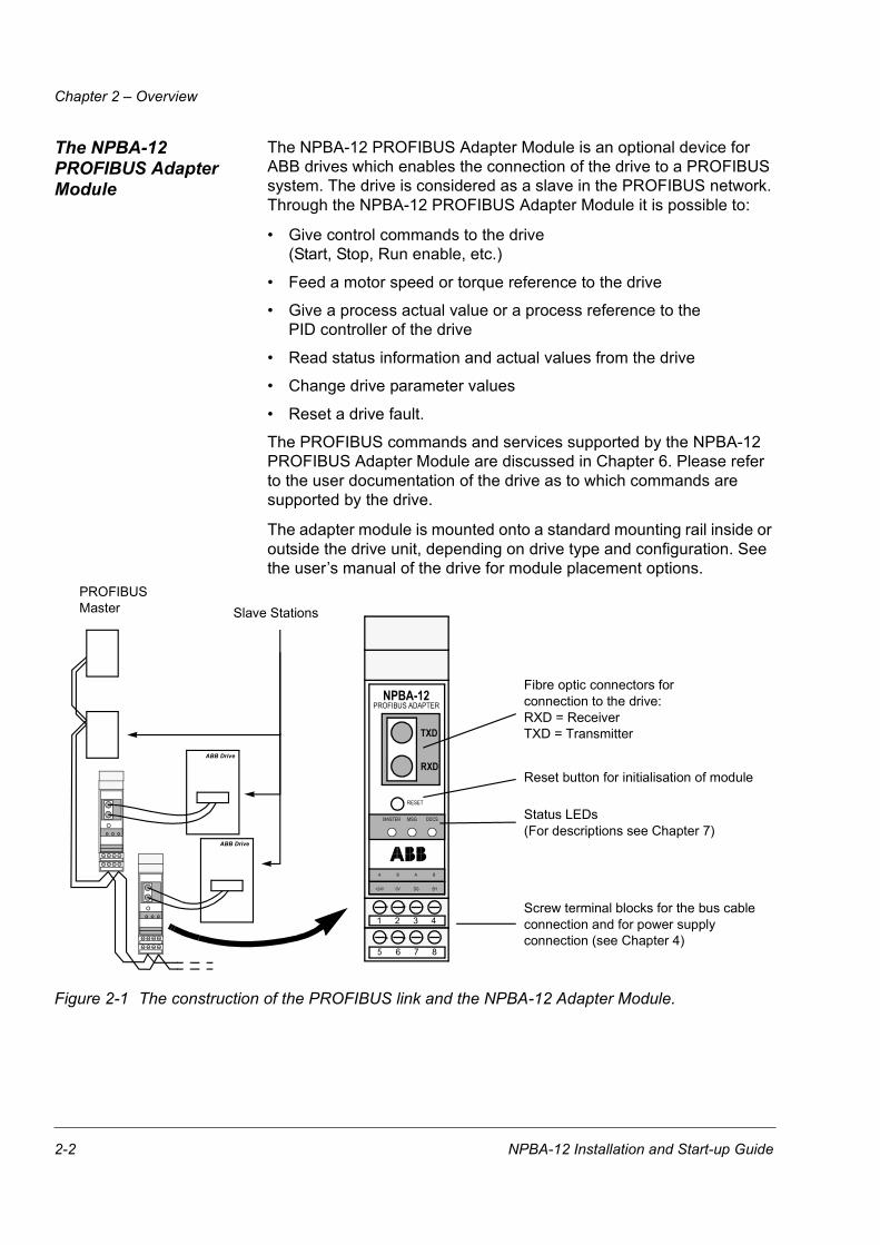
The adapter module is mounted onto a standard mounting rail inside or outside the drive unit, depending on drive type and configuration. See the user’s manual of the drive for module placement options.
Figure 2-1 The construction of the PROFIBUS link and the NPBA-12 Adapter Module.
Screw terminal blocks for the bus cable connection and for power supply connection (see Chapter 4)
Fibre optic connectors for connection to the drive:RXD = ReceiverTXD = Transmitter
Status LEDs(For descriptions see Chapter 7)
NPBA-12PROFIBUS ADAPTER
MASTER
A B
+24V 0V DG SH
RESET
TXD
RXD
5 6 7 8
1 2 3 4
MSG DDCS
A B
PROFIBUS Master Slave Stations
ABB Drive
ABB Drive
Reset button for initialisation of module
2-2 NPBA-12 Installation and Start-up Guide
Chapter 2 – Overview
Compatibility The NPBA-12 is compatible with:
• ABB Drives (see Chapter 5, Parameter no. 8, COMM PROFILE)
• All master stations that support the PROFIBUS-DP and -DPV1 protocols.
Delivery Check The option package for the NPBA-12 PROFIBUS Adapter Module contains:
• PROFIBUS Adapter Module, Type NPBA-12
• Two pairs (four pieces) of fibre optic cables for connecting the adapter to the drive
• Mounting rail
• This manual, the NPBA-12 Installation and Start-up Guide.
Warranty and LiabilityInformation
The warranty for your ABB drive and options covers manufacturing defects. The manufacturer carries no responsibility for damage due to transport or unpacking.
In no event and under no circumstances shall the manufacturer be lia-ble for damages and failures due to misuse, abuse, improper installa-tion, or abnormal conditions of temperature, dust, or corrosives, or failures due to operation above rated capacities. Nor shall the manu-facturer ever be liable for consequential and incidental damages.
The period of manufacturer's warranty is 12 months, and not more than 18 months, from the date of delivery. Extended warranty may be avail-able with certified start-up. Contact your local distributor for details.
Your local ABB Drives company or distributor may have a different war-ranty period, which is specified in their sales terms, conditions, and warranty terms.
If you have any questions concerning your ABB drive, contact your local distributor or ABB Drives office.
The technical data and specifications are valid at the time of printing. ABB reserves the right to subsequent alterations.
NPBA-12 Installation and Start-up Guide 2-3

Chapter 2 – Overview
2-4 NPBA-12 Installation and Start-up Guide
Chapter 3 – Mechanical Installation
Overview This chapter contains module mounting instructions. Depending on the drive, the module can be installed either inside or outside the drive housing or cabinet. See the user’s manual of the drive for module placement options.
Mounting Outside the Drive
Choose the location for the module. Note the following:
• The cabling instructions in Chapter 4 must be followed.
• The ambient conditions should be taken into account (see Appendix D). The degree of protection of the module is IP 20.
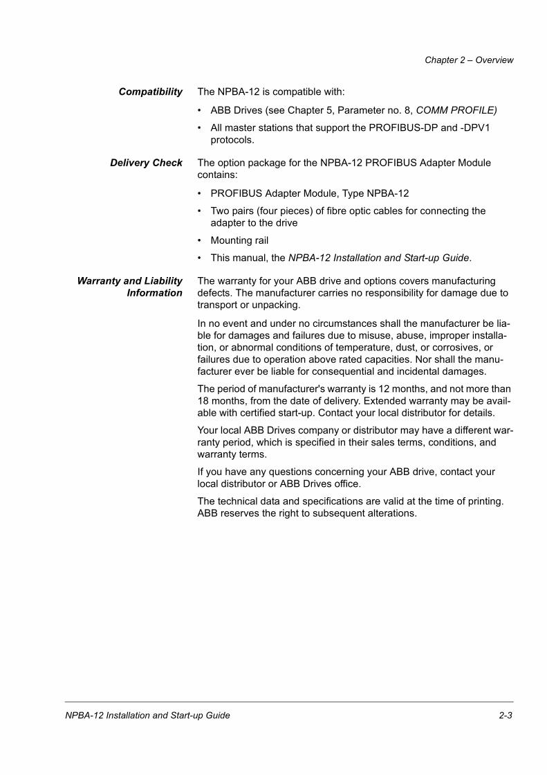
• Observe the free space requirements for the module (see the figure below) and the drive (see the drive documentation).
• Module earth is connected to the mounting rail by means of an earthing tab (see the figure below). The mounting rail onto which the option module is to be mounted must be earthed to a noiseless earth. If the rail is not mounted on a properly earthed base, a separate earthing conductor must be used. The conductor must be as short as possible and its cross-sectional area must be 6 mm2 at least. Note: No solid copper conductor may be used (stranded wire allowed only).
Mounting instructions:
1. Switch off all dangerous voltages in the enclosure that the module is to be mounted in.
2. Fasten the rail and ensure the proper earthing as described above.
3. Push the module onto the rail. The module can be released by pulling the locking spring with a screwdriver (see below).
EarthingTab
10 mm
10 mm
NPBA-12 Installation and Start-up Guide 3-1
Chapter 3 – Mechanical Installation
Mounting Inside the Drive
The work inside the drive should be carried out by a qualified electrician only.
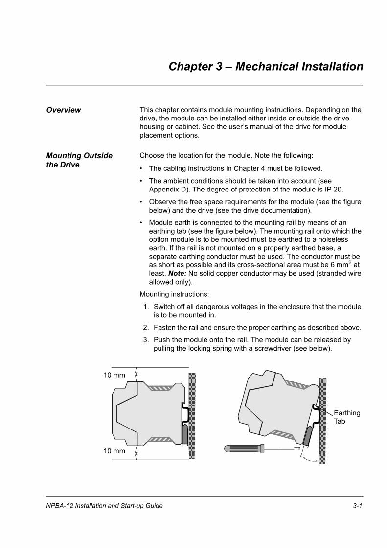
WARNING! Pay attention to the slowly discharging voltage of the capacitor bank and the voltages that are connected from external control circuits to the inputs and outputs of the drive.
WARNING! Do not touch the printed circuit boards. The integrated circuits are extremely sensitive to electrostatic discharge.
Mounting instructions:
1. Stop the drive.
2. Switch off the power supply of the drive and all dangerous voltages connected to the inputs and outputs.
3. Wait for five minutes to ensure that the capacitors in the intermediate circuit have discharged.
4. Remove the front cover of the drive.
5. Ensure that the mains cable, motor cable and capacitor bank (UDC+ and UDC–) are not powered.
6. Locate the position for the module (see the drive documentation). Fasten the mounting rail to its place if not already installed. Observe the free space requirements for the module (see the figure above).
7. Push the module onto the rail. The module can be released by pulling the locking spring with a screwdriver (see the figure above).
3-2 NPBA-12 Installation and Start-up Guide
Chapter 4 – Electrical Installation
Overview This chapter contains:
• general cabling instructions
• module earthing instructions
• bus termination instructions
• instructions for connecting the module to the drive and to the PROFIBUS bus.
WARNING! Before installation, switch off the drive power supply. Wait five minutes to ensure that the capacitor bank of the drive is discharged. Switch off all dangerous voltages connected from external control circuits to the inputs and outputs of the drive.
General Cabling Instructions
Arrange the bus cables as far away from the motor cables as possible. Avoid parallel runs. Use bushings at cable entries.
Handle fibre optic cables with care. When unplugging optic cables, always grab the connector, not the cable itself. Do not touch the ends of the fibres with bare hands as the fibre is extremely sensitive to dirt.
The maximum long term tensile load for the fibre optic cables is 1 N.The minimum short term bend radius is 25 mm.
Earthing the Module The NPBA-12 module earth is connected to the rail onto which the module is mounted. If the rail is fastened to an earthed metallic assembly plate, the module is automatically earthed, and no external earthing wire is needed. If the rail is fastened to a base that is not earthed, the rail must be connected to the nearest earthing terminal. However, the earthing wire should not be connected to the same terminal as the power cable screens. (See the mounting instructions in Chapter 3.)
NPBA-12 Installation and Start-up Guide 4-1
Chapter 4 – Electrical Installation
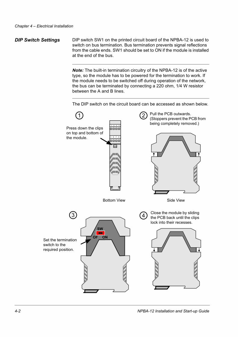
DIP Switch Settings DIP switch SW1 on the printed circuit board of the NPBA-12 is used to switch on bus termination. Bus termination prevents signal reflections from the cable ends. SW1 should be set to ON if the module is installed at the end of the bus.
Note: The built-in termination circuitry of the NPBA-12 is of the active type, so the module has to be powered for the termination to work. If the module needs to be switched off during operation of the network, the bus can be terminated by connecting a 220 ohm, 1/4 W resistor between the A and B lines.
The DIP switch on the circuit board can be accessed as shown below.
1 2 3 4
5 6 7 8
Press down the clips on top and bottom of the module.
Pull the PCB outwards. (Stoppers prevent the PCB from being completely removed.)
Set the termination switch to the required position.
1 2
3
SW
Bottom View Side View
Close the module by sliding the PCB back until the clips lock into their recesses.
4
OF ON
4-2 NPBA-12 Installation and Start-up Guide
Chapter 4 – Electrical Installation
NPBA-12 Connections
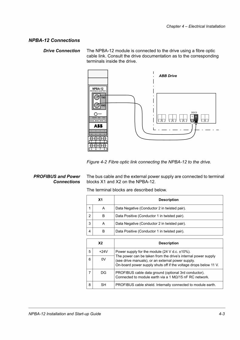
Drive Connection The NPBA-12 module is connected to the drive using a fibre optic cable link. Consult the drive documentation as to the corresponding terminals inside the drive.
Figure 4-2 Fibre optic link connecting the NPBA-12 to the drive.
PROFIBUS and PowerConnections
The bus cable and the external power supply are connected to terminal blocks X1 and X2 on the NPBA-12.
The terminal blocks are described below.
X1 Description
1 A Data Negative (Conductor 2 in twisted pair).
2 B Data Positive (Conductor 1 in twisted pair).
3 A Data Negative (Conductor 2 in twisted pair).
4 B Data Positive (Conductor 1 in twisted pair).
X2 Description
5 +24V Power supply for the module (24 V d.c. ±10%).The power can be taken from the drive’s internal power supply (see drive manuals), or an external power supply.On-board power supply shuts off if the voltage drops below 11 V.
6 0V
7 DG PROFIBUS cable data ground (optional 3rd conductor). Connected to module earth via a 1 MΩ/15 nF RC network.
8 SH PROFIBUS cable shield. Internally connected to module earth.
NPBA-12PROFIBUS ADAPTER
MASTER
A B
+24V 0V DG SH
RESET
TXD
RXD
5 6 7 8
1 2 3 4
MSG DDCS
A B
ABB Drive
RTT
DDCS
NPBA-12 Installation and Start-up Guide 4-3
Chapter 4 – Electrical Installation
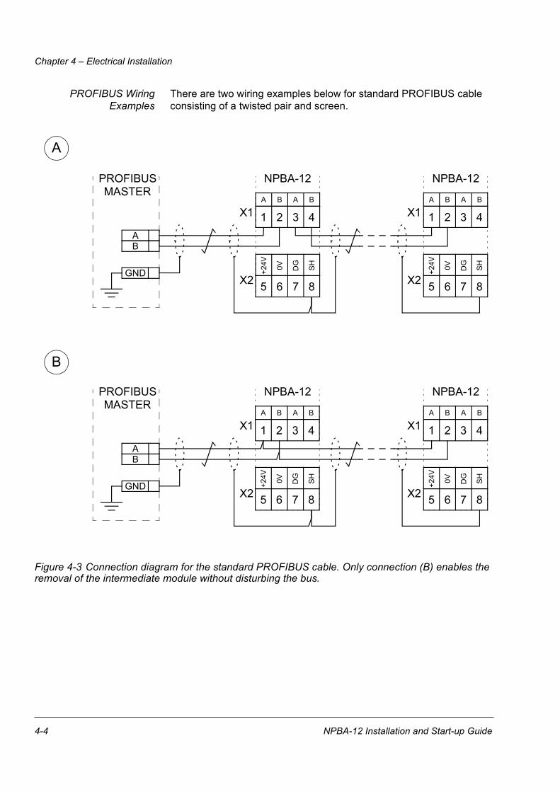
PROFIBUS WiringExamples
There are two wiring examples below for standard PROFIBUS cable consisting of a twisted pair and screen.
Figure 4-3 Connection diagram for the standard PROFIBUS cable. Only connection (B) enables the removal of the intermediate module without disturbing the bus.
A
B
PROFIBUS NPBA-12
X1 1 2 3 4
MASTER
BA
X1A B A B
NPBA-12
1 2 3 4A B A B
5 6 7 8
+24V 0V DG SH
5 6 7 8
+24V 0V DG SHGND
PROFIBUS NPBA-12
X1 1 2 3 4
MASTER
BA
X1A B A B
NPBA-12
1 2 3 4A B A B
5 6 7 8
+24V 0V DG SH
5 6 7 8
+24V 0V DG SHGND
X2 X2
X2 X2
4-4 NPBA-12 Installation and Start-up Guide
Chapter 5 – Programming
Overview This chapter gives information on configuring the PROFIBUS master station and the drive for communication through the NPBA-12 PROFIBUS Adapter Module.
Configuring the System
After the NPBA-12 PROFIBUS Adapter Module has been mechanically and electrically installed according to the instructions in Chapters 3and 4, the master station and the drive must be prepared for communication with the module.
The type definition (GSD) file required for configuration of the master station is available from www.profibus.com or your local ABB representative. The filename is ABB_6012.GSD.
Please refer to the master station documentation for more information.
PROFIBUS ConnectionConfiguration
The detailed procedure of activating the module for communication with the drive is dependent on drive type. (Normally, a parameter must be adjusted to activate the communication. See the drive documentation.)
As communication between the drive and the NPBA-12 is established, several configuration parameters are copied to the drive. These parameters – shown below in Table 5-1 – must be checked first and adjusted if necessary. The alternative selections for these parameters are discussed in more detail below the table.
Note: The new settings take effect only when the module is powered up or the RESET button pressed for the next time.
Note: In case the fibre optic cables are transferred from one drive to another without powering down the module, press the RESET button to refresh the configuration parameters in the module.
Note: The grouping, numbering, and adjustment procedure of parameters vary from drive to drive. See the drive documentation for information.
Data Transfer RatesSupported
The NPBA-12 supports the following PROFIBUS communication speeds: 9.6 kbit/s, 19.2 kbit/s, 45.45 kbit/s, 93.75 kbit/s, 187.5 kbit/s, 500 kbit/s, 1.5 Mbit/s, 3 Mbit/s, 6 Mbit/s, 12 Mbit/s.
The NPBA-12 automatically detects the communication speed used.
NPBA-12 Installation and Start-up Guide 5-1

Chapter 5 – Programming
Table 5-1 The NPBA-12 configuration parameters.
MODULE TYPE This parameter shows the module type and software version as detected by the drive. The value cannot be adjusted by the user.
If this parameter is undefined, the communication between the drive and the module has not been established.
PROTOCOL This parameter selects the protocol used.
DPThis setting can be used with PROFIBUS masters that support the DP or DPV1 protocol.
DPV1This setting must be used with DPV1-only PROFIBUS masters.
NPBA-02 MODEWhen an NPBA-01 or NPBA-02 module is replaced with an NPBA-12 module in an existing network, this setting can be used in order to avoid the reconfiguration of the PROFIBUS master.
PPO TYPE This parameter selects the PPO message type for the PROFIBUS connection. See Figure 6-1 for available PPO message types.
NODE NUMBER Each device on the PROFIBUS link must have a unique node number. This parameter is used to define a node number for the drive it is connected to.
FieldbusPar. No. Parameter Name Alternative Settings Default
Setting
1 MODULE TYPE (Read-only) NPBA-12 Vx.x
2 PROTOCOL (0) DP; (1) DPV1; (2) NPBA-02 MODE (0) DP
3 PPO TYPE (0) PPO 1; (1) PPO 2; (2) PPO 3; (3) PPO 4; (4) PPO 5 (0) PPO 1
4 NODE NUMBER 2 to 126 2
5 NO. OF DATA SETS 1 to 4 1
6 DATA SET INDEX (0) FBA DSET 1; (1) FBA DSET 10 (0) FBA DSET 1
7 CUT-OFF TIMEOUT 0 to 255 30
8 COMM PROFILE (0) ABB DRIVES; (1) CSA 2.8/3.0 (0) ABB DRIVES
9 CONTROL ZERO MODE (0) STOP; (1) FREEZE (0) STOP
5-2 NPBA-12 Installation and Start-up Guide
Chapter 5 – Programming
NO. OF DATA SETS This parameter defines the number of data sets sent in each direction in PPO messages; e.g.. if this parameter is set to 1, only data sets 1 (master to drive) and 2 (drive to master) are used. Setting this parameter to 4 enables all eight data sets shown in Figure 6-1: data sets with odd numbers (1,3,5,7) are sent by the master to the drive and those with even numbers (2,4,6,8) are sent by the drive to the master (providing DATA SET INDEX is set to FBA DSET 1). Please note that different drive types support different numbers of data sets; see the drive documentation.
DATA SET INDEX Defines the offset for data set indexes (numbers). See the drive documentation for information.
FBA DSET 1 (no offset) The first data set sent from the master to the drive (the Control Word) is Data Set 1 (DS1).
FBA DSET 10 (offset 9)The first data set sent from the master to the drive (the Control Word) is Data Set 10 (DS10).
CUT-OFF TIMEOUT This parameter defines the behaviour of the NPBA module in the event that no messages are received from the PROFIBUS controller.
0The NPBA cyclically sends the last valid Control Word and References to the drive until new values are received from the controller.
1 … 255The NPBA stops communicating with the drive after a timeout, the actual length of which equals the setting multiplied by 20 milliseconds. The behaviour of the drive in case the DDCS communication stops depends on its parameter settings; consult the drive documentation.
Normal operation is resumed after valid messages are again received from the controller.
NPBA-12 Installation and Start-up Guide 5-3

Chapter 5 – Programming
COMM PROFILE This parameter selects the communication profile used in the DDCS link between the drive and the NPBA-12. The setting to use is dependent on drive type and software version as indicated below. (The drive software version can be checked by viewing a parameter; see the drive documentation.)
ABB DRIVESThe NPBA-12 relays the Control Word “as is” from the PROFIBUS master to the drive. The Status Word is relayed to the master as received from the drive, except bit 15 which is used as a DDCS communication error indicator. The Control and Status Word bits are assigned as defined by the ABB Drives Profile (based on the PROFIBUS standard).
CSA 2.8/3.0The Control Word and the Status Word are altered in order to match the drive Control and Status Words to those defined by the PROFIBUS profile.
CONTROL ZERO MODE This parameter defines the operation of the NPBA module in the event that only messages consisting of zeros are received from the PROFIBUS controller. This is the case e.g. when the controller is switched from RUN to STOP mode.
STOPThe messages are forwarded to the drive as such. This will usually cause the drive to stop; for more information, consult the drive documentation.
FREEZEThe last-received valid Control Word and References are sent to the drive until new values are received from the PROFIBUS controller.
Drive Type Drive SW Version Setting to Use
ACS 400 1.0.5.6 or later ABB DRIVESACS 600 SingleDrive CSA 2.8x to CSA 3.0x CSA 2.8/3.0ACS 600 SingleDrive ACxA5000 or later ABB DRIVES
ACS 600 SingleDrive with PFC AHxA2000 CSA 2.8/3.0ACS 600 SingleDrive with PFC AHxA5000 or later ABB DRIVESACS 600 MultiDrive AMxM103a or later ABB DRIVES
ACS 600 MotionControl (ACP 600) APxA1100 or later ABB DRIVESACS 600 Pump & Fan Drive (ACF 600) AF0A1020 or later ABB DRIVESACS 600 CraneDrive (ACC 600) ACxA2000 or later ABB DRIVES
ACS 800 ASXR7000 or later ABB DRIVESACS 1000 ABB DRIVESACS 6000 ABB DRIVES
DCS 400 ABB DRIVESDCS 500 DC21x226 or later ABB DRIVES
5-4 NPBA-12 Installation and Start-up Guide
Chapter 5 – Programming
Control Locations ABB drives can receive control information from multiple sources including digital inputs, analogue inputs, the drive control panel and a communication module (e.g. NPBA-12). ABB drives allow the user to separately determine the source for each type of control information (Start, Stop, Direction, Reference, Fault Reset, etc.). In order to give the fieldbus master station the most complete control over the drive, the communication module must be selected as source for this information. See the user documentation of the drive for information on the selection parameters.
NPBA-12 Installation and Start-up Guide 5-5

Chapter 5 – Programming
5-6 NPBA-12 Installation and Start-up Guide
Chapter 6 – Communication
Overview This chapter describes the PROFIBUS messaging used in the communication with the drive.
PROFIBUS-DP The NPBA-12 module supports the PROFIBUS-DP protocol, including the DPV1 Extensions to the EN 50170 standard. PROFIBUS-DP is a distributed I/O system which enables the master to use a large number of peripheral modules and field devices. The data transfer is mainly cyclic: the master reads the input information from the slaves and sends the output information back to the slaves.
The PROFIBUS-DP protocol uses so-called PPOs (Parameter/Process Data Objects) in cyclic communication. See Figure 6-1 for the different PPO types and their composition.
Service Access Points The services of the PROFIBUS Data Link Layer (Layer 2) are used by PROFIBUS-DP through Service Access Points (SAPs). Precisely defined functions are assigned to individual SAPs.
For further information on Service Access Points, refer to the manual of the PROFIBUS master, PROFIDRIVE – The PROFIBUS Profile for Adjustable Speed Drives, or the EN 50170 standard.
CommunicationStart-up
The following Service Access Points (SAPs) are used to initiate DP communication:
SAP No. Short Name Name
61 Set_Prm Send Parameter Data
62 Chk_Cfg Check Configuration Data
60 Slave_Diag Read Slave Diagnostic Information
128 (Default) Data_Exch Transfer Input and Output Data
NPBA-12 Installation and Start-up Guide 6-1
Chapter 6 – Communication
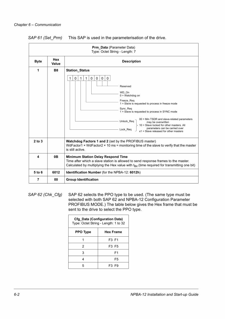
SAP 61 (Set_Prm) This SAP is used in the parameterisation of the drive.
SAP 62 (Chk_Cfg) SAP 62 selects the PPO type to be used. (The same type must be selected with both SAP 62 and NPBA-12 Configuration Parameter PROFIBUS MODE.) The table below gives the Hex frame that must be sent to the drive to select the PPO type.
Prm_Data (Parameter Data)Type: Octet String - Length: 7
Byte HexValue Description
1 B8 Station_Status
2 to 3 Watchdog Factors 1 and 2 (set by the PROFIBUS master)WdFactor1 × WdFactor2 × 10 ms = monitoring time of the slave to verify that the master is still active.
4 0B Minimum Station Delay Respond TimeTime after which a slave station is allowed to send response frames to the master. Calculated by multiplying the Hex value with tBit (time required for transmitting one bit)
5 to 6 6012 Identification Number (for the NPBA-12: 6012h)
7 00 Group Identification
Cfg_Data (Configuration Data)Type: Octet String - Length: 1 to 32
PPO Type Hex Frame
1 F3 F1
2 F3 F5
3 F1
4 F5
5 F3 F9
Reserved
Sync_Req
Unlock_Req
Lock_Req
1 = Slave is requested to process in SYNC mode
Freeze_Req1 = Slave is requested to process in freeze mode
WD_On0 = Watchdog on
1 0 1 1 0 0 0 0
00 = Min TSDR and slave-related parameters may be overwritten
10 = Slave locked for other masters. All parameters can be carried over
x1 = Slave released for other masters
6-2 NPBA-12 Installation and Start-up Guide
Chapter 6 – Communication
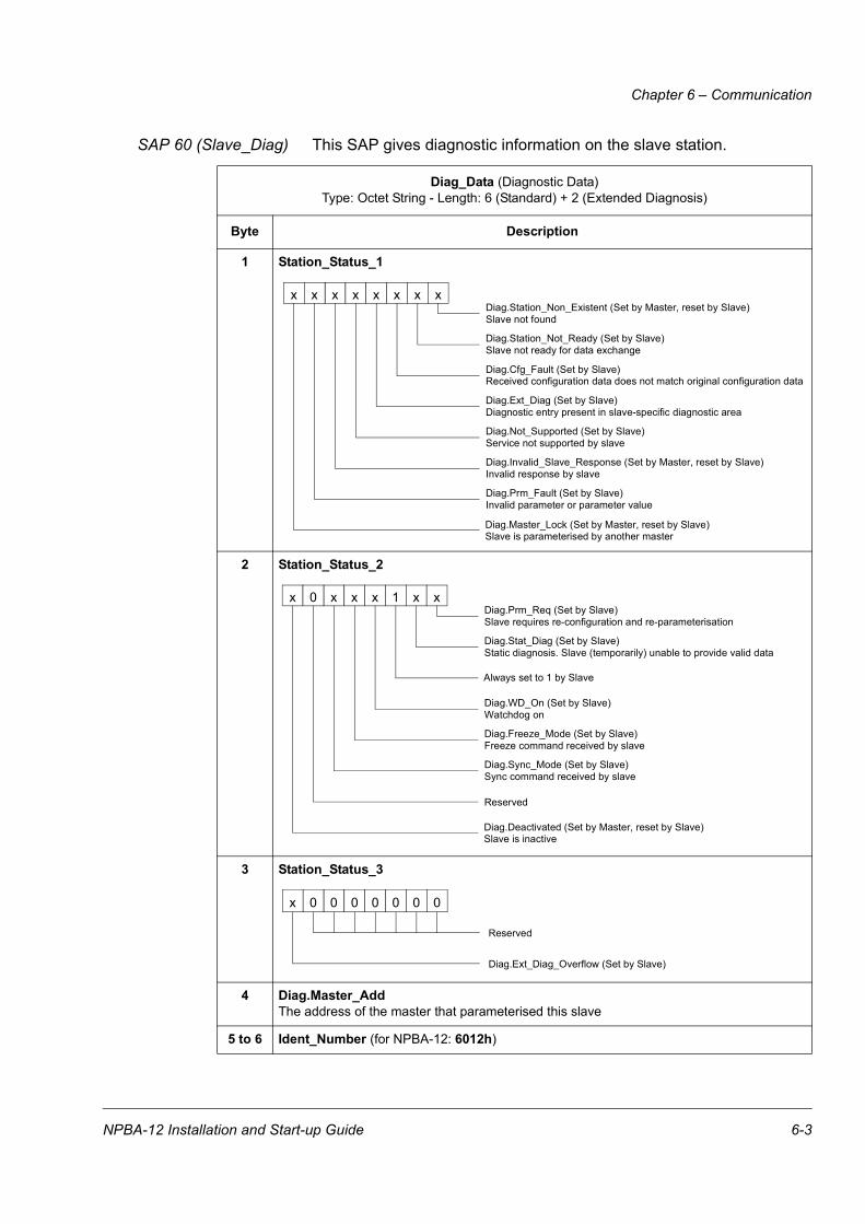
SAP 60 (Slave_Diag) This SAP gives diagnostic information on the slave station.
Diag_Data (Diagnostic Data)Type: Octet String - Length: 6 (Standard) + 2 (Extended Diagnosis)
Byte Description
1 Station_Status_1
2 Station_Status_2
3 Station_Status_3
4 Diag.Master_AddThe address of the master that parameterised this slave
5 to 6 Ident_Number (for NPBA-12: 6012h)
Diag.Master_Lock (Set by Master, reset by Slave)
x x x x x x x x
Slave is parameterised by another master
Diag.Prm_Fault (Set by Slave)Invalid parameter or parameter value
Diag.Invalid_Slave_Response (Set by Master, reset by Slave)Invalid response by slave
Diag.Not_Supported (Set by Slave)Service not supported by slave
Diag.Ext_Diag (Set by Slave)Diagnostic entry present in slave-specific diagnostic area
Diag.Cfg_Fault (Set by Slave)Received configuration data does not match original configuration data
Diag.Station_Not_Ready (Set by Slave)Slave not ready for data exchange
Diag.Station_Non_Existent (Set by Master, reset by Slave)Slave not found
Diag.Deactivated (Set by Master, reset by Slave)
x 0 x x x 1 x x
Slave is inactive
Reserved
Diag.Sync_Mode (Set by Slave)Sync command received by slave
Diag.Freeze_Mode (Set by Slave)Freeze command received by slave
Diag.WD_On (Set by Slave)Watchdog on
Diag.Stat_Diag (Set by Slave)Static diagnosis. Slave (temporarily) unable to provide valid data
Diag.Prm_Req (Set by Slave)Slave requires re-configuration and re-parameterisation
Always set to 1 by Slave
Diag.Ext_Diag_Overflow (Set by Slave)
Reserved
x 0 0 0 0 0 0 0
NPBA-12 Installation and Start-up Guide 6-3
Chapter 6 – Communication
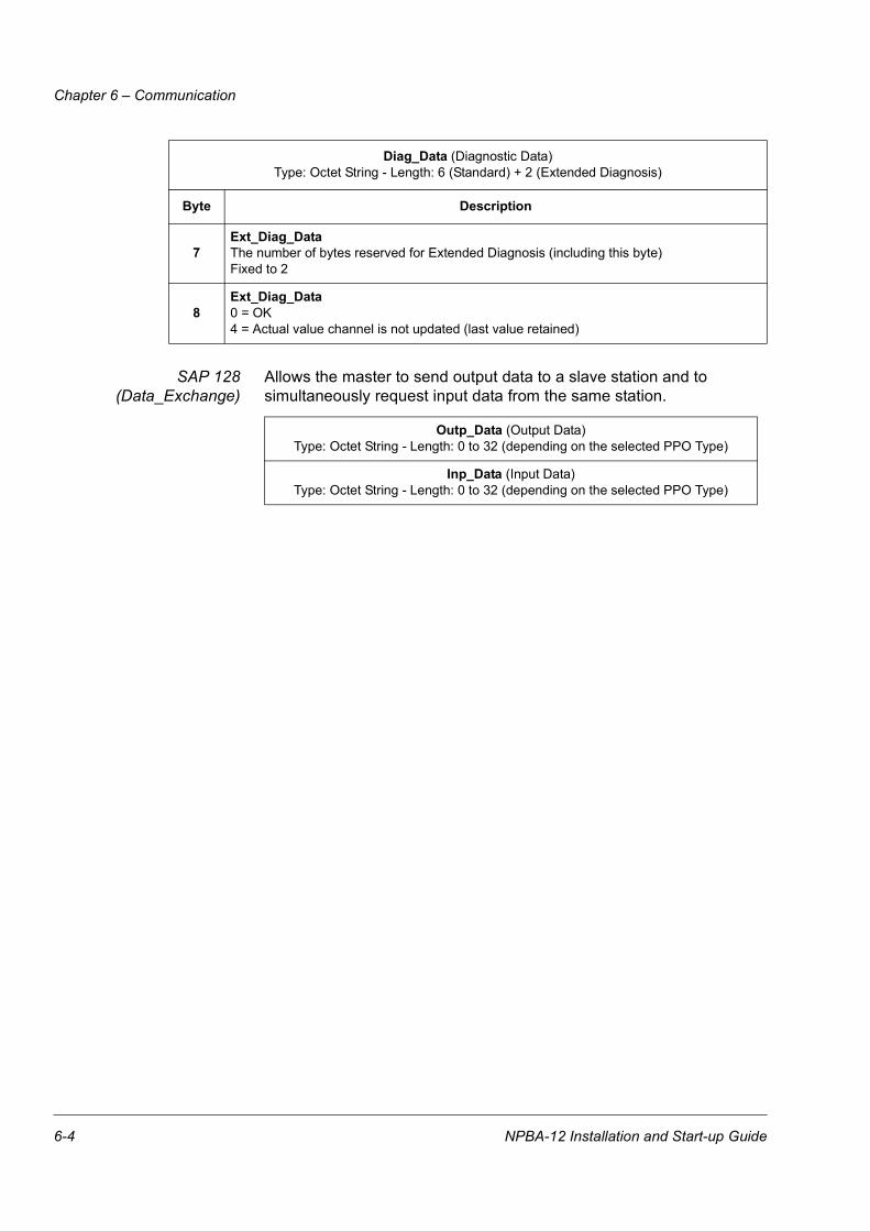
SAP 128(Data_Exchange)
Allows the master to send output data to a slave station and to simultaneously request input data from the same station.
7Ext_Diag_DataThe number of bytes reserved for Extended Diagnosis (including this byte)Fixed to 2
8Ext_Diag_Data0 = OK4 = Actual value channel is not updated (last value retained)
Outp_Data (Output Data)Type: Octet String - Length: 0 to 32 (depending on the selected PPO Type)
Inp_Data (Input Data)Type: Octet String - Length: 0 to 32 (depending on the selected PPO Type)
Diag_Data (Diagnostic Data)Type: Octet String - Length: 6 (Standard) + 2 (Extended Diagnosis)
Byte Description
6-4 NPBA-12 Installation and Start-up Guide
Chapter 6 – Communication
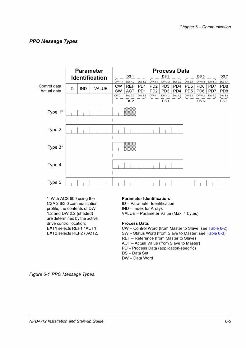
PPO Message Types
Figure 6-1 PPO Message Types.
Type 1*
Type 2
Type 3*
Type 4
Type 5
Parameter Process Data
CW REF PD1 PD2 PD3 PD4 PD5 PD6 PD7 PD8VALUEINDID
Identification
PD1SW ACT PD2 PD3 PD4 PD5 PD6 PD7 PD8
DS 1 DS 3 DS 5 DS 7
DS 2 DS 4 DS 6 DS 8
DW 1.1 DW 1.2 DW 1.3 DW 3.1 DW 3.2 DW 3.3 DW 5.1 DW 5.2 DW 5.3 DW 7.1
DW 2.1 DW 2.2 DW 2.3 DW 4.1 DW 4.2 DW 4.3 DW 6.1 DW 6.2 DW 6.3 DW 8.1
* With ACS 600 using the CSA 2.8/3.0 communication profile, the contents of DW 1.2 and DW 2.2 (shaded) are determined by the active drive control location: EXT1 selects REF1 / ACT1, EXT2 selects REF2 / ACT2.
Parameter Identification:ID – Parameter IdentificationIND – Index for ArraysVALUE – Parameter Value (Max. 4 bytes)
Process Data:CW – Control Word (from Master to Slave; see Table 6-2)SW – Status Word (from Slave to Master; see Table 6-3)REF – Reference (from Master to Slave)ACT – Actual Value (from Slave to Master)PD – Process Data (application-specific)DS – Data SetDW – Data Word
Control dataActual data
NPBA-12 Installation and Start-up Guide 6-5

Chapter 6 – Communication
The Control Word andthe Status Word
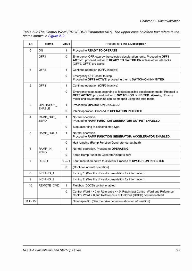
The Control Word (PROFIBUS Parameter 967) is the principal means for controlling the drive from a fieldbus system. It is sent by the fieldbus master station to the drive, the adapter module acting as a link. The drive switches between its states according to the bit-coded instructions on the Control Word, and returns status information to the master in the Status Word (PROFIBUS Parameter 968).
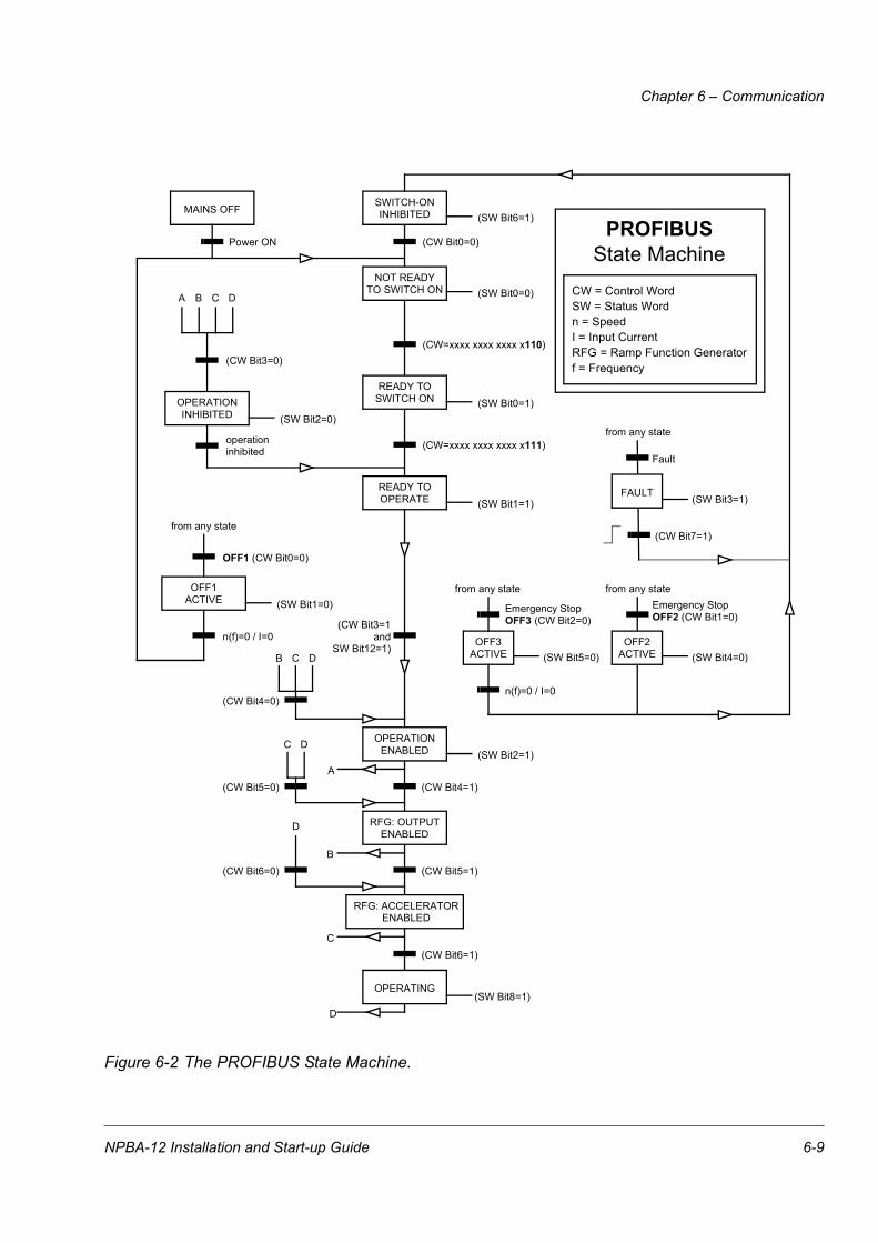
The contents of the Control Word and the Status Word are detailed in Table 6-2 and Table 6-3 respectively; see the drive documentation for information on the drive-specific bits. The drive states are presented in the PROFIBUS State Machine (Figure 6-2).
References References are 16-bit words containing a sign bit and a 15-bit integer. A negative reference (indicating reversed direction of rotation) is formed by calculating the two’s complement from the corresponding positive reference.
ABB drives can receive control information from multiple sources including analogue and digital inputs, the drive control panel and a communication module (e.g. NPBA-12). In order to have the drive controlled through PROFIBUS, the communication module must be defined as the source for control information, e.g. Reference. The scaling of the integer received from the master as Reference is drive-specific. See its Programming Manual for available control source selections and Reference scaling factors.
Actual Values Actual Values are 16-bit words containing information on the operation of the drive. The functions to be monitored are selected with a drive parameter. The scaling of the integers sent to the master as Actual Values depends on the selected function. Please refer to the drive documentation.
6-6 NPBA-12 Installation and Start-up Guide
Chapter 6 – Communication
Table 6-2 The Control Word (PROFIBUS Parameter 967). The upper case boldface text refers to the states shown in Figure 6-2.
Bit Name Value Proceed to STATE/Description
0 ON 1 Proceed to READY TO OPERATE
OFF1 0 Emergency OFF, stop by the selected deceleration ramp. Proceed to OFF1 ACTIVE; proceed further to READY TO SWITCH ON unless other interlocks (OFF2, OFF3) are active
1 OFF2 1 Continue operation (OFF2 inactive)
0 Emergency OFF, coast to stop.Proceed to OFF2 ACTIVE; proceed further to SWITCH-ON INHIBITED
2 OFF3 1 Continue operation (OFF3 inactive)
0 Emergency stop, stop according to fastest possible deceleration mode. Proceed to OFF3 ACTIVE; proceed further to SWITCH-ON INHIBITED. Warning: Ensure motor and driven machine can be stopped using this stop mode.
3 OPERATION_ENABLE
1 Proceed to OPERATION ENABLED
0 Inhibit operation. Proceed to OPERATION INHIBITED
4 RAMP_OUT_ZERO
1 Normal operation.Proceed to RAMP FUNCTION GENERATOR: OUTPUT ENABLED
0 Stop according to selected stop type
5 RAMP_HOLD 1 Normal operation.Proceed to RAMP FUNCTION GENERATOR: ACCELERATOR ENABLED
0 Halt ramping (Ramp Function Generator output held)
6 RAMP_IN_ZERO
1 Normal operation. Proceed to OPERATING
0 Force Ramp Function Generator input to zero
7 RESET 0 1 Fault reset if an active fault exists. Proceed to SWITCH-ON INHIBITED
0 (Continue normal operation)
8 INCHING_1 Inching 1. (See the drive documentation for information)
9 INCHING_2 Inching 2. (See the drive documentation for information)
10 REMOTE_CMD 1 Fieldbus (DDCS) control enabled
0 Control Word <> 0 or Reference <> 0: Retain last Control Word and ReferenceControl Word = 0 and Reference = 0: Fieldbus (DDCS) control enabled
11 to 15 Drive-specific. (See the drive documentation for information)
NPBA-12 Installation and Start-up Guide 6-7

Chapter 6 – Communication
Table 6-3 The Status Word (PROFIBUS Parameter 968). The upper case boldface text refers to the states shown in Figure 6-2.
Bit Name Value STATE/Description
0 RDY_ON 1 READY TO SWITCH ON
0 NOT READY TO SWITCH ON
1 RDY_RUN 1 READY TO OPERATE
0 OFF1 ACTIVE
2 RDY_REF 1 OPERATION ENABLED
0
3 TRIPPED 1 FAULT
0 No fault
4 OFF_2_STA 1 OFF2 inactive
0 OFF2 ACTIVE
5 OFF_3_STA 1 OFF3 inactive
0 OFF3 ACTIVE
6 SWC_ON_INHIB 1 SWITCH-ON INHIBITED
0
7 ALARM 1 Warning/Alarm
0 No Warning/Alarm
8 AT_SETPOINT 1 OPERATING. Actual value equals reference value (= is within tolerance limits)
0 Actual value differs from reference value (= is outside tolerance limits)
9 REMOTE 1 Drive control location: REMOTE
0 Drive control location: LOCAL
10 ABOVE_LIMIT 1 Actual frequency or speed value equals or is greater than supervision limit
0 Actual frequency or speed value is within supervision limit
11 to 14 Drive-specific
15 DDCS_ERROR 1 Error in DDCS communication (between fieldbus adapter module and drive).Adapter ceases to communicate with the master
0 DDCS communication OK
6-8 NPBA-12 Installation and Start-up Guide
Chapter 6 – Communication
Figure 6-2 The PROFIBUS State Machine.
MAINS OFF
Power ON (CW Bit0=0)
SWITCH-ONINHIBITED (SW Bit6=1)
NOT READYTO SWITCH ON (SW Bit0=0)
READY TOSWITCH ON
from any state
(CW=xxxx xxxx xxxx x110)
PROFIBUSState Machine
READY TOOPERATE (SW Bit1=1)
n(f)=0 / I=0
OPERATIONINHIBITED (SW Bit2=0)
A B C D
(CW Bit3=0)
operationinhibited
OFF1 (CW Bit0=0)
OFF1ACTIVE (SW Bit1=0)
(SW Bit0=1)
(CW Bit3=1and
SW Bit12=1)
C D
(CW Bit5=0)
OPERATIONENABLED (SW Bit2=1)
(SW Bit5=0)
from any state from any state
Emergency StopOFF3 (CW Bit2=0)
n(f)=0 / I=0
OFF3ACTIVE
Emergency StopOFF2 (CW Bit1=0)
(SW Bit4=0)OFF2
ACTIVE
RFG: OUTPUTENABLED
RFG: ACCELERATORENABLED
OPERATING
B
B C D
(CW Bit4=0)
(CW Bit4=1)
(CW Bit5=1)
D
(CW Bit6=0)
A
C(CW Bit6=1)
CW = Control WordSW = Status Wordn = SpeedI = Input Current
(SW Bit8=1)
RFG = Ramp Function Generatorf = Frequency
D
from any state
Fault
(SW Bit3=1)FAULT
(CW Bit7=1)
(CW=xxxx xxxx xxxx x111)
NPBA-12 Installation and Start-up Guide 6-9

Chapter 6 – Communication
Parameters in Cyclic Communication (DP)
In cyclic PROFIBUS-DP communication, parameter data is transferred in PPO message types 1, 2 and 5 (see Figure 6-1). The Parameter Identification part consists of eight bytes (see below).
The Request Label is used by the master when transmitting data to the slave, while the Response Label is used by the slave as a positive or negative acknowledgement. The tables below show the Request/Response functions.
Request Labels (from Master to Slave)
Request FunctionResponse Labels
Ackn. (+) Ackn. (-)
0 No task 0 –
1 Request parameter value 1, 2 7
2 Change parameter value (word) 1 7, 8
3 Change parameter value (double word) 2 7, 8
*4 Request description element 3 7
*5 Change description element 3 7, 8
*6 Request parameter value (array) 4, 5 7, 8
*7 Change parameter value (array word) 4 7, 8
*8 Change parameter value (array double word) 5 7,8
*9 Request number of array elements 6 7
*Not supported by NPBA-12 SW version V1.0
ID IND VALUE
15 14 13 12 11 10 9 8 7 6 5 4 3 2 1 0
Request LabelResponse Label
*Request Signal
Parameter Number
Process DataParameter
Identification
*Not used (=0)
CW REF(PD1, PD2...)SW ACT
6-10 NPBA-12 Installation and Start-up Guide

Chapter 6 – Communication
Response Label (Acknowledgement from Slave to Master)
Ackn. Function
0 No response
1 Transfer parameter value (word)
2 Transfer parameter value (double word)
3 Transfer description element
4 Transfer parameter value (array word)
5 Transfer parameter value (array double word)
6 Transfer number of array elements
7 Task cannot be executed, followed by error number0 = Illegal PNU1 = Parameter value cannot be changed2 = Lower or upper limit violated3 = Erroneous sub-index4 = No array5 = Incorrect data type6 = Setting not allowed (can only be reset)7 = Descriptive element cannot be changed8 = PPO write, requested in the IR, not available9 = Descriptive data not available10 = Access group incorrect11 = No parameter change rights12 = Password incorrect13 = Text cannot be read in cyclic data transmission14 = Name cannot be read in cyclic data transmission15 = Text array not available16 = PPO write missing17 = Task cannot be executed due to operating status18 = Other error19 = Data cannot be read in cyclic data transfer103 = Request not supported301 = Internal communication (DDCS) fault
8 No parameter change rights for PKW interface
9 Parameter data signal (word)
10 Parameter data signal (double word)
NPBA-12 Installation and Start-up Guide 6-11

Chapter 6 – Communication
Example: Write In this example, current parameter settings are saved to the FLASH memory of the drive. This is done by setting the value of PROFIBUS Parameter No. 971 (3CBh) to 1.
Note that the drive always observes the Control Word (CW) and Reference (REF) bytes. The values shown below are examples.
Example: Read In this example, PROFIBUS Parameter No. 918 is used to read the station number of the slave.
The slave returns its station number (2).
Parameters in Acyclic Communication (DPV1)
At the time of publishing, acyclic communication is not implemented in the NPBA-12.
Write:Request 23 CB 00 00 00 00 00 01 04 7F 34 15
Response 13 CB 00 00 00 00 00 00 03 37 34 15
Read:Request 13 96 00 00 00 00 00 00 04 7F 34 15
Response 13 96 00 00 00 00 00 02 03 37 34 15
Param. Value CW REFIND
Param. Number (971 Dec)
Request (Parameter value write)
Response (Parameter value updated)
Param. Number (971 Dec)
IND Param. Value SW ACT
Param. Value CW REFIND
Param. Number (918 Dec)
Request (Parameter value read)
Response (Parameter value updated)
Param. Number (918 Dec)
IND Param. Value SW ACT
6-12 NPBA-12 Installation and Start-up Guide

Chapter 7 – Fault Tracing
Status LED Indications The tables below describe the Status LED indications during both the start-up sequence and operation.
Table 7-1 LED indications during the NPBA-12 start-up sequence.
Start-up StageStatus LED Indications
MASTER MSG DDCS
Power-on OFF OFF GREEN then RED then OFF
OFF GREEN then RED then OFF OFF
GREEN then RED then OFF OFF OFF
DDCS linkinitialisation
OFF OFF FLASHING GREEN (in progress)then GREEN
Transfer rate detection
FLASHING GREEN (in progress)then GREEN
OFF GREEN
PROFIBUScommunication establishment
GREEN FLASHING GREEN (in progress)then GREEN
GREEN
Operation GREEN GREEN GREEN
NPBA-12 Installation and Start-up Guide 7-1
Chapter 7 – Fault Tracing
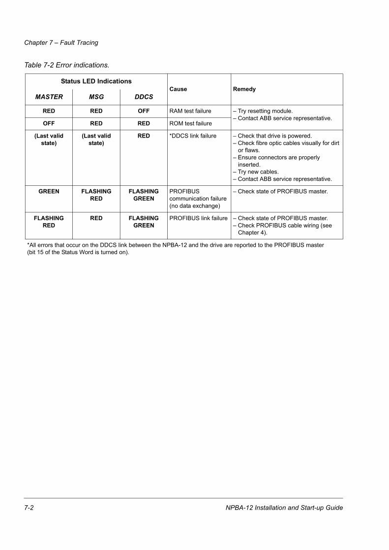
Table 7-2 Error indications.
Status LED IndicationsCause Remedy
MASTER MSG DDCS
RED RED OFF RAM test failure – Try resetting module.– Contact ABB service representative.
OFF RED RED ROM test failure
(Last valid state)
(Last valid state)
RED *DDCS link failure – Check that drive is powered.– Check fibre optic cables visually for dirt
or flaws.– Ensure connectors are properly
inserted.– Try new cables.– Contact ABB service representative.
GREEN FLASHING RED
FLASHING GREEN
PROFIBUS communication failure(no data exchange)
– Check state of PROFIBUS master.
FLASHING RED
RED FLASHING GREEN
PROFIBUS link failure – Check state of PROFIBUS master.– Check PROFIBUS cable wiring (see
Chapter 4).
*All errors that occur on the DDCS link between the NPBA-12 and the drive are reported to the PROFIBUS master(bit 15 of the Status Word is turned on).
7-2 NPBA-12 Installation and Start-up Guide
Appendix A – PROFIBUS Parameters
The table below shows the PROFIBUS Profile-specific Parameters.
PROFIBUSPar. No. Parameter Name Data
Type R/W Description
918 NODE ADDRESS UINT16 R Node address of the deviceAllowable values: 2, ..., 126
947 FAULT NUMBER UINT16 R The last fault occurred in the drive0h = No fault1000h = Generic fault
963 CURRENT BAUD RATE UINT16 R Detected baud rate0 = 12 Mbit/s1 = 6 Mbit/s2 = 3 Mbit/s3 = 1.5 Mbit/s4 = 500 kbit/s5 = 187.5 kbit/s6 = 93.75 kbit/s7 = 45.45 kbit/s8 = 19.2 kbit/s9 = 9.6 kbit/s255 = Invalid baud rate
964 DEVICE IDENTIFICATION UINT16 R Identification number of this device (6012h)
965 PROFILE NUMBER UINT16 R Profile number of this device (0302h)
967 CONTROL WORD UINT16 R 16-bit word for controlling the drive
968 STATUS WORD UINT16 R 16-bit word indicating drive status
971 STORE UINT16 R/W 0 = No action1 = Save drive parameters to non-volatile memory
996* SET DAY COUNTER UINT16 W Sets the day counter of the real-time clock of the drive. Day 1 corresponds to 1 January 1980.
997* SET TIME COUNTER UINT32 W Sets the time counter of the real-time clock of the drive. The value corresponds to the number of 100 µs ticks since midnight.
*The values of Parameters 996 and 997 are sent to the drive when parameter 997 is written.
NPBA-12 Installation and Start-up Guide A-1

Appendix A – PROFIBUS Parameters
A-2 NPBA-12 Installation and Start-up Guide

Appendix B – Definitions and Abbreviations
PROFIBUS Definitions
Acyclic Communication Communication in which messages are sent only once on request
Array Parameter consisting of data fields of equal data type
Broadcast Non-acknowledged message from master to all bus participants (compare Multicast)
Command Word See Control Word
Communication Object Any object of a real device that can be communicated with (variable, program, data range, etc.). Stored locally in the Object Dictionary
Control Word 16-bit word from master to slave with bit-coded control signals. (Sometimes called the Command Word)
Cyclic Communication Communication in which Parameter-/Process Data-Objects are sent cyclically at pre-defined intervals
Device Class Classification according to the number of profile functions included in the device
Drivecast Broad- and Multicast, a special message frame for drives
Fault Event that leads to tripping of the device
GSD File ASCII-format device description file in a specified form. Each device (active & passive stations) on PROFIBUS has to have its own GSD File. GSD Files for various master stations are available from your local ABB representative.
Index Access reference for Objects in PROFIBUS
Information Report Non-acknowledged message from master to one or all groups of bus participants
Master Control system with bus initiative. In PROFIBUS terminology, master stations are also called active stations
Multicast Non-acknowledged message from master to one group of bus participants (compare Broadcast)
Name Symbolic name of a parameter
Nibble Set of 4 bits
Object Dictionary Local storage of all Communication Objects recognised by a device
Object List List of all accessible objects
Parameter Value that can be accessed as Object, e.g. variable, constant, signal
NPBA-12 Installation and Start-up Guide B-1

Appendix B – Definitions and Abbreviations
Parameter Description Specification of a parameter
Parameter Number Parameter address
Parameter/ProcessData Object Special object that contains Parameter and Process Data
Process Data Data that contains Control Word and Reference value or Status Word and Actual value. May also contain other (user-definable) control information
Profile Adaptation of the protocol for certain application field, e.g. drives
Request Label Coded information specifying the required service for the parameter part sent from master to slave
Response Label Coded information specifying the required service for the parameter part sent from slave to master
Slave Passive bus participant. In PROFIBUS terminology, slave stations (or slaves) are also called passive stations
Status Word 16-bit word from slave to master with bit-coded status messages
Warning Signal caused by an existing alarm which does not lead to tripping of the device
B-2 NPBA-12 Installation and Start-up Guide

Appendix B – Definitions and Abbreviations
PROFIBUS AbbreviationsThe text in italics is the original German term.
.con Confirmation
.ind Indication
.req Request
.res Response
ACT Actual ValueIstwert
AK Request Label/Response LabelAuftragskennung/Antwortkennung
ALI Application Layer Interface
CR Communication ReferenceKommunikationsreferenz (Kommunikationsbeziehung)
DP Decentralised PeripheryDezentrale Peripherie
DP-ALI Application Layer Interface for DP
DPV1 PROFIBUS-DP Extensions to the EN 50170 standard,including e.g. acyclic data exchange
FDL Fieldbus Data Link
FMS Fieldbus Message Specification
FSU Manufacturer Specific InterfaceFirmenspezifischer Umsetzer
HIW Main Actual ValueHauptistwert
HSW Main ReferenceHauptsollwert
ISW see ACT
KR (KB) see CR
PA Process AutomationProzessautomatisierung
PD Process DataProzessdaten
PKE Parameter IdentificationParameter-Kennung
PKW Parameter Identification ValueParameter-Kennung-Wert
NPBA-12 Installation and Start-up Guide B-3
Appendix B – Definitions and Abbreviations
PNU Parameter NumberParameternummer
PPO Parameter/Process Data ObjectParameter-/Prozessdaten-Objekt
PWE Parameter ValueParameter-Wert
PZD see PD
PZDO Process Data ObjectProzessdatenobjekt
SAP Service Access Point
SOW ReferenceSollwert
SPM Request SignalSpontanmeldung
STW Control WordSteuerwort
ZSW Status WordZustandswort
B-4 NPBA-12 Installation and Start-up Guide
Appendix C – Technical Data
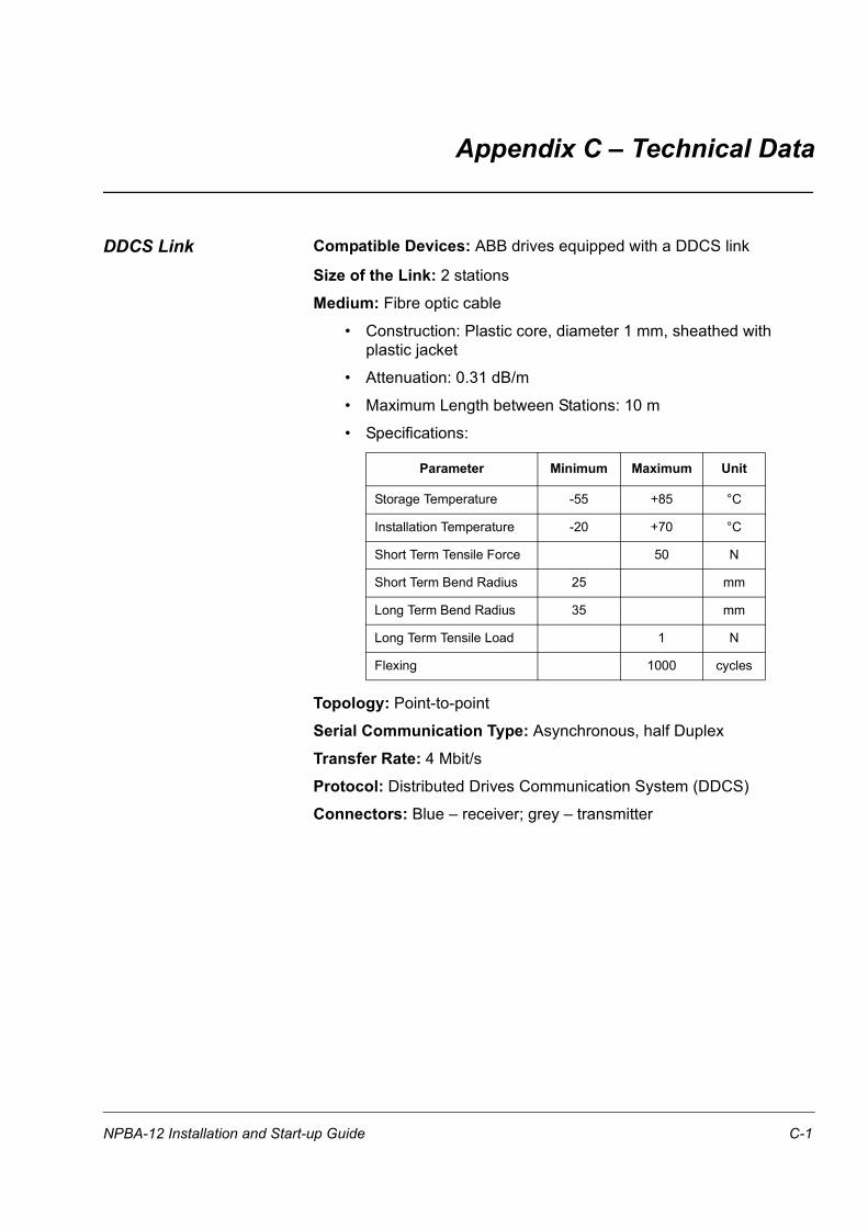
DDCS Link Compatible Devices: ABB drives equipped with a DDCS link
Size of the Link: 2 stations
Medium: Fibre optic cable
• Construction: Plastic core, diameter 1 mm, sheathed with plastic jacket
• Attenuation: 0.31 dB/m
• Maximum Length between Stations: 10 m
• Specifications:
Topology: Point-to-point
Serial Communication Type: Asynchronous, half Duplex
Transfer Rate: 4 Mbit/s
Protocol: Distributed Drives Communication System (DDCS)
Connectors: Blue – receiver; grey – transmitter
Parameter Minimum Maximum Unit
Storage Temperature -55 +85 °C
Installation Temperature -20 +70 °C
Short Term Tensile Force 50 N
Short Term Bend Radius 25 mm
Long Term Bend Radius 35 mm
Long Term Tensile Load 1 N
Flexing 1000 cycles
NPBA-12 Installation and Start-up Guide C-1

Appendix C – Technical Data
Fieldbus Link Compatible Devices: All devices compatible with the PROFIBUS-DP and PROFIBUS-DPV1 protocols
Size of the Link: 127 stations including repeaters (31 stations and 1 repeater per segment)
Medium: Shielded, twisted pair RS485 cable
• Termination: of active type, built in the NPBA-12 Module
• Specifications:
• Maximum Bus Length (m):
Topology: Multi-drop
Serial Communication Type: Asynchronous, half Duplex
Transfer Rate: 9.6, 19.2, 44.45, 93.75, 187.5, 500, 1500, 3000, 6000, or 12000 kbit/s
Protocol: PROFIBUS-DP, PROFIBUS-DPV1
Parameter Line APROFIBUS-DP
Line BDIN 19245 Part 1 Unit
Impedance 135 to 165(3 to 20 MHz)
100 to 130(f > 100 kHz)
Ω
Capacitance < 30 < 60 pF/m
Resistance < 110 – Ω/km
Wire gauge > 0.64 > 0.53 mm
Conductor area > 0.34 > 0.22 mm2
Transfer Rate (kbit/s)
≤ 93.75 187.5 500 1500 3000 6000 12000
Line A 1200 1000 400 200 100 100 100
Line B 1200 600 200 – – – –
C-2 NPBA-12 Installation and Start-up Guide
Appendix C – Technical Data
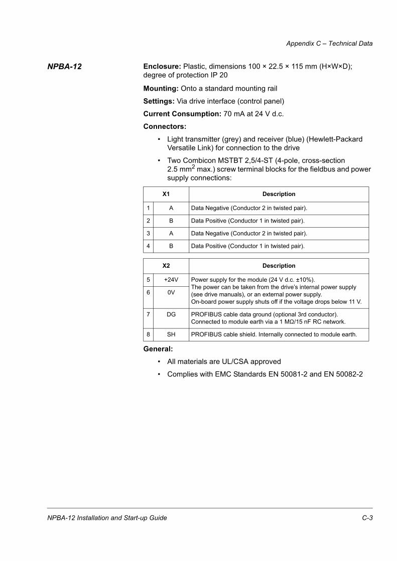
NPBA-12 Enclosure: Plastic, dimensions 100 × 22.5 × 115 mm (H×W×D); degree of protection IP 20
Mounting: Onto a standard mounting rail
Settings: Via drive interface (control panel)
Current Consumption: 70 mA at 24 V d.c.
Connectors:• Light transmitter (grey) and receiver (blue) (Hewlett-Packard
Versatile Link) for connection to the drive
• Two Combicon MSTBT 2,5/4-ST (4-pole, cross-section 2.5 mm2 max.) screw terminal blocks for the fieldbus and power supply connections:
General:• All materials are UL/CSA approved
• Complies with EMC Standards EN 50081-2 and EN 50082-2
X1 Description
1 A Data Negative (Conductor 2 in twisted pair).
2 B Data Positive (Conductor 1 in twisted pair).
3 A Data Negative (Conductor 2 in twisted pair).
4 B Data Positive (Conductor 1 in twisted pair).
X2 Description
5 +24V Power supply for the module (24 V d.c. ±10%).The power can be taken from the drive’s internal power supply (see drive manuals), or an external power supply.On-board power supply shuts off if the voltage drops below 11 V.
6 0V
7 DG PROFIBUS cable data ground (optional 3rd conductor). Connected to module earth via a 1 MΩ/15 nF RC network.
8 SH PROFIBUS cable shield. Internally connected to module earth.
NPBA-12 Installation and Start-up Guide C-3

Appendix C – Technical Data
C-4 NPBA-12 Installation and Start-up Guide
Appendix D – Ambient Conditions
Ambient Conditions, Operation
Ambient operating conditions refer to the conditions the option module is subjected to when installed for stationary use.
Air Temperature: 0 to +50 °C
Relative Humidity: 5 to 95%, no condensation allowed. Maximum allowed relative humidity is 60% in the presence of corrosive gases.
Contamination Levels: Chemical gases: IEC 721-3-3, Class 3C2Solid particles: IEC 721-3-3, Class 3S2
Installation Site Altitude: 0 to 2000 m. If the installation site is above 2000 m, contact local ABB representative.
Vibration: Max 0.3 mm (2 to 9 Hz), max 1 m/s2 (9 to 200 Hz) sinusoidal (IEC 68-2-6)
Shock: Max 70 m/s2, 22 ms (IEC 68-2-27)
Ambient Conditions, Storage
Ambient storage conditions refer to the conditions the option module is subjected to during storage in the protective package.
Temperature: -40 to +70 °C.
Relative Humidity: Less than 95%, no condensation allowed
Atmospheric Pressure: 70 to 106 kPa
Vibration: Max 1.5 mm (2 to 9 Hz), max 5 m/s2 (9 to 200 Hz) sinusoidal (IEC 68-2-6)
Shock: Max 100 m/s2, 11 ms (IEC 68-2-27)
Ambient Conditions, Transportation
Ambient transportation conditions refer to the conditions the option module is subjected to during transportation in the protective package.
Temperature: -40 to +70 °C
Relative Humidity: Less than 95%, no condensation allowed.
Atmospheric Pressure: 60 to 106 kPa
Vibration: Max 3.5 mm (2 to 9 Hz), max 15 m/s2 (9 to 200 Hz) sinusoidal (IEC 68-2-6)
Shock: Max 100 m/s2, 11 ms (IEC 68-2-27)
Bump: Max 300 m/s2, 6 ms (IEC 68-2-29)
Free Fall: 250 mm
NPBA-12 Installation and Start-up Guide D-1

Appendix D – Ambient Conditions
D-2 NPBA-12 Installation and Start-up Guide


ABB OyAC DrivesP.O.Box 184FIN-00381 HelsinkiFINLANDTelephone: +358 10 222 000
NPB
A-12
/EN
3BFE
643
4158
8 R
0125
REV
BEF
FEC
TIVE
: 06.
10.2
003
ABB Inc.Automation TechnologiesDrives & Motors16250 West Glendale DriveNew Berlin, WI 53151USA
Fax: +358 10 222 2681Internet: www.abb.com/automation
Telephone: 262 785-3416800-HELP-365
Fax: 262 785-8525


![PROFIBUS DP bus interface, PROFIBUS DP [BU 2700]...Sicherheit/PROFIBUS DP [BU 2700]/Bestimmungsgemäße Ver wendung PROFIBUS DP @ 8\mod_1461835577600_388.docx @ 2249429 @ 2 @ 1 2.1](https://static.fdocuments.in/doc/165x107/60b54c574bd00c04b50e633d/profibus-dp-bus-interface-profibus-dp-bu-2700-sicherheitprofibus-dp-bu.jpg)