Product Manual • Maintenance • Startup •...
44
Part number GL-E223-ADOC 0311 This manual must only be used by a qualified heating installer/service technician. BEFORE installing, read all instruc- tions in this manual and all other information shipped with the water heater. Perform steps in the order given. Failure to comply could result in severe personal injury, death or substantial property damage. • Installation • Startup • Maintenance • Parts Product Manual Indirect-Fired Water Heaters User — Read important user safety information found on page 3, page 24 and page 25. Installation and service should only be performed by a qualified service technician. Retain this manual for future reference. ® ® TM
Transcript of Product Manual • Maintenance • Startup •...

Part number GL-E223-ADOC 0311
Thismanualmustonlybeusedbyaqualifiedheatinginstaller/servicetechnician.BEFOREinstalling,readallinstruc-tionsinthismanualandallotherinformationshippedwiththewaterheater.Performstepsintheordergiven.Failuretocomplycouldresultinseverepersonalinjury,deathorsubstantialpropertydamage.
• Installation
• Startup
• Maintenance
• PartsProduct Manual
Indirect-Fired Water Heaters
User — Readimportantusersafetyinformationfoundonpage3,page24andpage25.Installationandserviceshouldonlybeperformedbyaqualifiedservicetechnician.Retainthismanualforfuturereference.
®
®TM

AQUA PLUS indirect-fired water heaters — Product Manual
Contents
Please read before proceeding 3Whenservicingwaterheater . . . . . . . . . . . . . . . . . . . .3
Operatingrestrictions. . . . . . . . . . . . . . . . . . . . . . . . 3
Boilerwaterrestrictions . . . . . . . . . . . . . . . . . . . . . . .3
Location . . . . . . . . . . . . . . . . . . . . . . . . . . . . . . .3
Pre-installation 4Codes. . . . . . . . . . . . . . . . . . . . . . . . . . . . . . . . . 4
Coderestrictions . . . . . . . . . . . . . . . . . . . . . . . . . . .4
Waterheaterplacement . . . . . . . . . . . . . . . . . . . . . . . 4
Installlevellinglegs . . . . . . . . . . . . . . . . . . . . . . . . .4
Domesticwaterpipingrequirements. . . . . . . . . . . . . . . .5
Waterheateroperatingrestrictions. . . . . . . . . . . . . . . . .5
Boilerwaterrestrictions . . . . . . . . . . . . . . . . . . . . . . .5
HotWaterCanScald!........................5
Domestic water piping 6Pipingoverview . . . . . . . . . . . . . . . . . . . . . . . . . . .6
Recirculation 8Maintainingdomesticwatertemperatureinthesupplypiping .8
Timedelayatfixtures . . . . . . . . . . . . . . . . . . . . . . . .8
Balancing. . . . . . . . . . . . . . . . . . . . . . . . . . . . . . . 8
Componentsrequired. . . . . . . . . . . . . . . . . . . . . . . . 8
Connectingtothewaterheater. . . . . . . . . . . . . . . . . . . 8
Components . . . . . . . . . . . . . . . . . . . . . . . . . . . . 10
Operation. . . . . . . . . . . . . . . . . . . . . . . . . . . . . . 10
Potentialproblems . . . . . . . . . . . . . . . . . . . . . . . . . 10
Boiler-side piping 11
Connecting to a low-pressure steam boiler 18Fillingthepiping . . . . . . . . . . . . . . . . . . . . . . . . . . 19
Boiler-side wiring and controls 20Wiringrequirements. . . . . . . . . . . . . . . . . . . . . . . . 20
Circulators . . . . . . . . . . . . . . . . . . . . . . . . . . . . . 20
ZoneValves . . . . . . . . . . . . . . . . . . . . . . . . . . . . . 20
Wiringtothewaterheater. . . . . . . . . . . . . . . . . . . . . 20
Wiringoptions . . . . . . . . . . . . . . . . . . . . . . . . . . . 20
Usedomesticpriority . . . . . . . . . . . . . . . . . . . . . . . 20
Wiring — zoning with circulators 21
Wiring — zoning with zone valves 22
Water heater filling and start-up 23Boilerwaterrestrictions . . . . . . . . . . . . . . . . . . . . . . 23
Maximumboiler-sideflowrate . . . . . . . . . . . . . . . . . . 23
Fillingthedomesticwatertank. . . . . . . . . . . . . . . . . . 23
Start-upandoperation . . . . . . . . . . . . . . . . . . . . . . 23
Start-upchecklist . . . . . . . . . . . . . . . . . . . . . . . . . 23
Water heater temperature adjustment 24Settingthethermostat . . . . . . . . . . . . . . . . . . . . . . . 24
HotWaterCanScald!.......................24
Water heater maintenance 25ANNUALstart-upbyqualifiedservicetechnician . . . . . . . 25
Inspectanodeandwaterheaterinterior . . . . . . . . . . . . . 26
Drainthewaterheaterifnecessaryduringshutdownperiods. 26
Troubleshooting 27Troubleshootingprocedures . . . . . . . . . . . . . . . . . . . 27
Preparationfortroubleshooting . . . . . . . . . . . . . . . . . 27
Replacement parts 39
AHRI ratings 40
Ratings with 200°F boiler supply water 41
Ratings with 190°F boiler supply water 42
Ratings with 180°F boiler supply water 43
Dimensions 44
PartnumberGL-E223-ADOC03112

AQUA PLUS indirect-fired water heaters — Product Manual
Please read before proceeding
Failuretoadheretotheguidelinesonthispagecanresultinseverepersonalinjury,deathorsubstantialpropertydamage.
Readallinstructionsbeforeinstalling.Failuretofollowallinstruc-tionsinproperordercancauseseverepersonalinjury,deathorsubstantialpropertydamage.
When servicing water heater• Toavoidelectricshock,disconnectelectricalsupplybefore
performingmaintenance.
• Toavoidsevereburns,allowwaterheatertocoolbeforeper-formingmaintenance.
Operating restrictions• Maximumdomestichotwatertemperature:residentialsizes
—160°F, commercialsizes—180°F.Payattentiontothewatertemperaturewarningsthroughoutthismanual.
• Maximumboilerwatertemperature—200°F.
• Maximumworkingpressurefortank—150PSIG.
• Waterchemistrylimits:• hardness—lessthan6grains/gal.• pH—above6andlessthan8.• chlorides—lessthan200ppm.
Boiler water restrictions• Thoroughly flush the boiler system (without water heater
connected)toremovesediment.
• Thewaterheaterheatexchangercanbedamagedbybuild-uporcorrosionduetosediment.
• Boilerwater(includingadditives)mustbepracticallynon-toxic,havingtoxicityratingorclassof1,aslistedinClinicalToxicologyofCommercialProducts.
• Ifantifreezeisusedinboilersystem:• Local codes may require a backflow preventer on cold
watersupplyline.• Useantifreezespecificallyintendedforhydronicheating
systems.Inhibitedpropyleneglycolisrecommended.• Followboilermanualinstructionsforantifreezeusage.• Do not use automotive, ethylene glycol or petroleum-
basedantifreeze.Donotuseanyundilutedantifreeze.
Location• Thiswaterheaterisnotintendedforoutdoorinstallation.
• Install the water heater so if the tank or any connectionsshould leak, the water flow will not cause damage to areanearwaterheater,ortolowerfloorsofstructure.Whensuchlocationscannotbeavoided,installasuitabledrainpanunderwaterheater.Drainpansareavailableatyourlocalplumbingsupplystore.
• Thisproductisdesignedforverticalinstallationonly.
Whencallingorwritingaboutthewaterheater—Pleasehavethewaterheaterse-rialnumberfromtheserialnumberlabel,located on the back side of the waterheater,adjacenttotheratingplate.
Any claims for damage or shortage inshipment must be filed immediatelyagainstthetransportationcompanybytheconsignee.
Hazard definitionsThefollowingdefinedtermsareusedthroughoutthismanualtobringattentiontothepresenceofhazardsof various risk levels or to important informationconcerningthelifeoftheproduct.
Indicates presence of hazards that willcause severe personal injury, death orsubstantialpropertydamage.
Indicates presence of hazards that cancause severe personal injury, death orsubstantialpropertydamage.
Indicates presence of hazards that willor cancauseminorpersonal injuryorpropertydamage.
Indicatesspecialinstructionsoninstalla-tion,operationormaintenancethatareimportant but not related to personalinjuryorpropertydamage.
This manual provides installation andoperation guidelines forWeil-McLainAQUA PLUS indirect water heaters.Theinstallerisresponsibleforensuringthattheinstallationcomplieswiththismanual, the boiler manual and all ap-plicablecodes.
Massachusetts installations — The
water heater must be installed by a li-
censed plumber.The installation must
follow all Massachusetts code require-
ments.Thedomesticwaterpipingmust
comply with the piping shown in this
manual. See“Domestic water piping,”
page6,fordetailsandcoderequirements.
PartnumberGL-E223-ADOC0311 3

AQUA PLUS indirect-fired water heaters — Product Manual
Pre-installation
Figure 1 Clearance recommendationsCodes1. Installationmustconformwithinstructionsinthis
manualand,whereapplicable:• local,state,provincial,andnationalcodes,laws,
regulationsandordinances.• in Canada — B149.1 or B149.2 Installation
Code.
2. AQUAPLUSwaterheatersareexemptfromASMESectionVIII,Division1CodeconstructionperIn-terpretationVIII-1-86-136.Checkwithlocalcodesforapplicability.
3. Whererecommendationsinthismanualdifferfromlocalornationalcodes,localornationalcodestakeprecedence.
Code restrictions
National Standard Plumbing Code1. Single-wallheatexchangerinwaterheatercomplies
withNationalStandardPlumbingCode,providedthat:a. boilerwater(includingadditives)ispractically
non-toxic,havingtoxicityratingorclassof1,aslistedinClinicalToxicologyofCommercialProducts,and
b. boilerwaterpressureislimitedtomaximum30PSIGbyapprovedreliefvalve.
Uniform Plumbing Code1. Single-wallheatexchangersarepermittedifthey
satisfyallofthefollowingrequirements—a. Theheattransfermediumispotablewateror
containsonlysubstanceswhicharerecognizedassafebytheU.S.FoodandDrugAdminis-tration.
b. The pressure of the heat transfer medium ismaintainedlessthanthenormalminimumop-eratingpressureofthepotablewatersystem.
c. Exception:Steamcomplyingwith#a,above.d. The equipment is permanently labeled to
indicatethatonlyadditivesrecognizedassafebytheFDAshallbeusedintheheattransfermedium.
2. Other heat exchanger designs may be permittedwhereapprovedbytheAdministrativeAuthority.
Recommended clearancesInstallationlocationmustprovideadequateclearancesforservicingandproperoperationofthewaterheater.SeeFigure1.
• 1”clearanceispermissibletoeithersideofwaterheater,buttheInstruc-tionlabelorotherlabelsmaybehidden.
• Top(vertical)clearanceis12”minimum.
• Refertoboilermanualforboilerclearances.
Clearance to combustible materials1. Provideatleast½”clearancebetweenallhotwaterpipesandcombus-
tiblematerials.
Water heater placement1. Readandcomplywith“Location,”page3ofthismanual.
2. Selectaconvenientlocationforthewaterheater,basedondomesticandboilerpipinghook-ups.
3. Keepingthedistancebetweenboilerandwaterheatershortwill:• reducepipingheatloss.• provideminimumfrictionloss.
Install levelling legs1. Carefullytipthewaterheaterontoitsside.
2. Screwthefourlevellinglegsintothebase.
3. Returnthewaterheatertotheuprightpositionandsetinplace.
4. Adjustthelegsasnecessarytolevelthewaterheater.
PartnumberGL-E223-ADOC03114
AQUA PLUS indirect-fired water heaters — Product Manual
Pre-installation (continued)
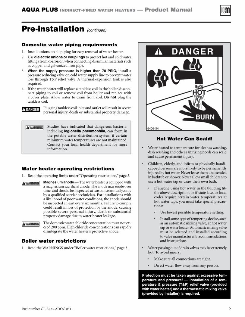
Hot Water Can Scald!
• Waterheatedtotemperatureforclotheswashing,dishwashingandothersanitizingneedscanscaldandcausepermanentinjury.
• Children,elderly,andinfirmorphysicallyhandi-cappedpersonsaremorelikelytobepermanentlyinjuredbyhotwater.Neverleavethemunattendedinbathtuborshower.Neverallowsmallchildrentouseahotwatertapordrawtheirownbath.
• Ifanyoneusinghotwaterinthebuildingfitstheabovedescription,orifstatelawsorlocalcodes require certain water temperatures athotwatertaps,youmusttakespecialprecau-tions:
• Uselowestpossibletemperaturesetting.
• Installsometypeoftemperingdevice,suchasanautomaticmixingvalve,athotwatertaporwaterheater.Automaticmixingvalvemustbe selectedand installedaccordingtovalvemanufacturer’srecommendationsandinstructions.
• Waterpassingoutofdrainvalvesmaybeextremelyhot.Toavoidinjury:
• Makesureallconnectionsaretight.
• Directwaterflowawayfromanyperson.
Protection must be taken against excessive tem-perature and pressure! — Installation of a tem-perature & pressure (T&P) relief valve (provided with water heater) and a thermostatic mixing valve (provided by installer) is required.
Domestic water piping requirements1. Installunionsonallpipingforeasyremovalofwaterheater.
2. Usedielectric unions or couplingstoprotecthotandcoldwaterfittingsfromcorrosionwhenconnectingdissimilarmaterialssuchascopperandgalvanizedironpipe.
3. When the supply pressure is higher than 70 PSIG, install apressurereducingvalveoncoldwatersupplylinetopreventwaterlossthroughT&Preliefvalve.Athermalexpansiontankisalsorequired.
4. Ifthewaterheaterwillreplaceatanklesscoilintheboiler,discon-nectpipingtocoilorremovecoil fromboilerandreplacewitha cover plate.Allow water to drain from coil. Do not plug thetanklesscoil.
Pluggingtanklesscoilinletandoutletwillresultinseverepersonalinjury,deathorsubstantialpropertydamage.
Studies have indicated that dangerous bacteria,including legionella pneumophila, can form inthe potable water distribution system if certainminimumwatertemperaturesarenotmaintained.Contact your local health department for moreinformation.
Water heater operating restrictions1. Readtheoperatinglimitsunder“Operatingrestrictions,”page3.
Magnesium anode—Thewaterheaterisequippedwithamagnesiumsacrificialanode.Theanodemayerodeovertime,andshouldbeinspectedatleastonceannually,onlybyaqualifiedservicetechnician.Forinstallationswithalikelihoodofpoorwaterconditions,theanodeshouldbeinspectedatleasteverysixmonths.Failuretocomplycouldresultinlossofprotectionbytheanode,causingpossible severe personal injury, death or substantialpropertydamageduetowaterheaterleakage.
Thedomesticwaterchlorideconcentrationmustnotex-ceed200ppm.Highchlorideconcentrationscanrapidlydisintegratethewaterheater’sprotectiveanode.
Boiler water restrictions1. ReadtheWARNINGSunder“Boilerwaterrestrictions,”page3.
PartnumberGL-E223-ADOC0311 5

AQUA PLUS indirect-fired water heaters — Product Manual
Domestic water piping
Figure 2 DHW pipingPiping overview
THERMAL ExPANSIoN TANk — If abackflowpreventer,checkvalve,orpres-surereducingvalveispipedoncoldwaterinletofwaterheater,youmustinstallanexpansiontankoncoldwatersupplylineto prevent normal thermal expansionfromrepeatedlyforcingopenT&Preliefvalve.
TheT&Preliefvalveisnotintendedforconstantduty,suchasreliefofpressuredue to repeated normal system expan-sion.Refertoexpansiontankmanufac-turer’sinstructionsforpropersizing.
Failuretocomplycouldresultinseverepersonal injury, death or substantialpropertydamage.
General applications 1. Figure2—Thispipingconfigurationcanbeusedin
mostcases,exceptwherelocalcodesrequirespecialcomponentsorpipingnotillustrated.
2. Somecodesmayrequiretheitemslistedasoptional,suchasavacuumbreakerontheinletline,orre-circulationpiping.
Massachusetts applications
1. For Massachusetts code applications, or asrequiredelsewherebylocalcodes, install thefol-lowingoptions.a. ThermalsiphononDHWinletandoutlet.b. Vacuumbreakerondomesticwaterinletline.c. Recirculation—Massachusetts codeapplica-
tionsrequirerecirculationpipingorheat-tracedpipingifthedistancefromthewaterheatertothefurthestfixtureexceeds100feet.Seepage8fordetails.
Figure 3 Piping connection sizes
ModelAQUA PLUS
Connections (inches NPT)
DHW in/out
Boiler water in/out
Recirculation tapping
35 ¾ 1 ¾
45 ¾ 1 ¾
55 ¾ 1 ¾
85 1 1 ¾
105 1 1 ¾
PartnumberGL-E223-ADOC03116

AQUA PLUS indirect-fired water heaters — Product Manual
Domestic water piping (continued)
LEGENDforFigure2,page6
Domesticwatersuppliedtofixturesthatcouldposean injuryhazarddue tohigh temperature, suchasshowers and faucets, should be equipped with atemperatureregulatingdevice,suchasananti-scald mixing valve.
When the supply pressure is higher than 70 PSIG,install a pressure reducing valve on cold watersupplylinetopreventwaterlossthroughT&Preliefvalve.Athermalexpansiontankisalsorequired.
Thissymbol,whereusedinthismanual,indicatestheitemisrequiredbyMassachusettscode.
This symbol indicates the item is optional, unlessrequiredbyapplicablecodes.
1 Domestic cold water inlet connection — see Fig-ure 3, page 6 for size
2 Domestic hot water outlet connection — see Fig-ure 3, page 6 for size
3 Domestic recirculation connection — see Fig-ure 3, page 6 for size
4 Boiler water inlet to coil — see Figure 3, page 6 for size
5 Boiler water outlet from coil — see Figure 3, page 6 for size
6 Drain valve — provided by installer • InstalladrainvalveontheDHWinlettothewaterheater
asshown.
7 Piping from drain valve
• Pipefromdraintofloordrain,ifavailable.
8 T&P valve connection
9 T&P relief valve — supplied with water heater
• UseonlytheT&Pvalvesuppliedwiththewaterheater.SeeReplacementpartsforpartnumber.
• InstalltheT&Preliefvalveinthetopcentertapping,asshown.
10T&P relief valve discharge piping —
• mustbemadeofmaterialserviceablefortemperaturesof250°Forgreater.
• mustbedirectedsothathotwaterflowsawayfromallpersons.
• mustbedirectedtoasuitableplacefordisposal.• mustbeinstalledsoastoallowcompletedrainingofthe
T&Preliefvalveanddischargeline.• mustNOTbeexcessivelylong—usingmorethan2el-
bowsor15feetofpipingcanreducedischargecapacity.• mustNOTbedirectlyconnectedtoadrain—terminate
dischargepipingwithin6”fromfloor—refer to localcodes.
• mustNOTbeplugged,reducedorrestricted.• mustNOTbesubjectedtofreezing.
DonotinstallanyvalvebetweenT&Preliefvalveandtank connection, or on T&P relief valve dischargepiping.DonotplugT&Preliefvalveoritsdischargepiping.ImproperplacementandpipingofT&Pre-liefvalvecancauseseverepersonalinjury,deathorsubstantialpropertydamage.
11Temperature adjustment knob
12Anode access
• Theanode is speciallymade for thiswaterheater.UseonlytheanodeavailablefromWeil-McLain,aslistedinReplacementparts.
13Mixing valve — —RECoMMENDED
• See Replacement parts for thermostatic mixing valvesavailablefromWeil-McLain.
14Domestic cold water supply
When the water supply pressure is higher than70 PSIG, install a pressure-reducing valve on thecoldwater supply line toprevent leakage fromtheT&Preliefvalve.Athermalexpansiontankisalsorequired.
15Domestic mixed-temperature water supply to system (whenused—requiresmixingvalve)
16Domestic high-temperature hot water supply to system
17Heat trap loops (12” minimum) —
18Isolation valves
19Thermal expansion tank —
• REQUIREDifcoldwaterlineisequippedwithabackflowpreventerorpressurereducingvalve—seeExPANSIoN TANk WARNINGonpage6.
20Shock arrester —
Dishwashers,clotheswashers,andfast-closingpositiveshutoffvalvesincorporatedinthesystemallcontrib-utetocreatingwatershock.Installawaterhammerarrestertopreventdamagetopipesandappliances.Seecontrolmanufacturer’sinstructionsforapplica-tionandinstallation.
21Unions
• Usedielectricunionsorcouplingstoprotecthotandcoldwaterfittingsfromcorrosionwhenconnectingdissimilarmaterialssuchascopperandgalvanizedironpipe.
22Backflow preventer — — — (required for Commonwealth of Massachusetts)
23Vacuum breaker —
24Pressure reducing valve —
• REQUIRED when the supply pressure is higher than70PSIG—A thermal expansion tank is also required.
PartnumberGL-E223-ADOC0311 7

AQUA PLUS indirect-fired water heaters — Product Manual
Recirculation
Massachusetts codeapplicationsrequirerecircu-lationpipingorheat-tracedpipingifthedistancefromthewaterheatertothefurthestfixtureexceeds100feet.
Maintaining domestic water temperature in the supply piping
1. Recirculationisusedtoreducewaittimeforwateruse,tominimize hot water and energy waste caused during thewaitingperiod, and to prevent degradation of the systemsupplywatertemperature.ASPErecommendsrecirculationwhenthedistancefromthewaterheatertothefurthestfix-tureexceeds100feetorthetimelagforhotwatertoreachafixture(s)exceeds30seconds.
2. Consult local codes andAmerican Society of PlumbingEngineers(ASPE)DomesticWaterHeatingDesignManual,1998,forfurtherinformation.
Time delay at fixtures
1. Figure4,page9isfromtheASPEDomesticWaterHeatingDesignManual,1998.Itshowsthetimerequiredforusablehotwatertoarriveatafixturebasedonthefixtureflowrate(availablefromindustryandmanufacturer’sdata)andthelengthanddiameterofthedead-endbranchpipesupplyingthefixture.
2. Thetimelagshouldgenerallynotexceed30seconds.
3. Forresidentialandofficeapplications,theownermaypreferalimitof10seconds.
4. YoucanuseFigure4asaguidetodeterminingthelocationofcirculationreturnlinesrelativetofixtures.
Balancing
1. Whenmultiplebranchesareconnectedtothesupplypip-ing, each branch must be connected to the recirculationsystem.
a. Ateachoftheseconnectionstothereturnpiping,installshutoffvalves,aflowmeteringdevice,checkvalveandastrainerasshowninFigure5,page9.
b. Check local codes for specific installation require-ments.
2. Thesebranchesmustbebalancedtopreventpipeerosionandunacceptabletimedelaysatsomefixtures.
3. Balancingoptionsincludecircuitsetters,memorystopvalvesorfactorypresetdevices(withflowmeteringprovisioninthepiping).
Components required
1. Forresidentialapplications,consultcirculatormanufacturer’sdata for circulator selection and additional componentsrequired.
2. Onmostcommercialsystems,installthedevicesshowninFigure5,page9,andanyotherdevicesorpipingmethodsrequiredbylocalcodes.
a. Thecheckvalvesarerequiredtopreventfixturesfromtakinghotwaterthroughthereturnlines.
b. Shutoffvalvesareneededtoallowcleaningandreplacingbalancingdevices.
c. Include strainers to remove sediment which coulddamagethecirculatorand/oraffecttheflowbalancingdevices.
3. Sizethecirculatorandpipingbasedonthetemperaturedropallowedbetweenthewateravailableatthewaterheaterandthewaterdeliveredatthefixture.
a. Thereturnpipingwillalmostalwaysbesmallerthanthesupplypiping,butshouldneverbesmallerthan½”topreventproblemswiththecirculator.
4. Makeprovisionforremovalofairinallreturnlines.Wherethe returns cannot be vented by topmost fixtures in thesystem,installautomaticairventingatthetopofthereturnpiping.
Connecting to the water heater
1. Install the domestic water components as shown in Fig-ure2,page6.
2. SeeFigure6,page10forthepipingrequiredtothewaterheater.
—Continuedonpage10—
PartnumberGL-E223-ADOC03118
AQUA PLUS indirect-fired water heaters — Product Manual
Recirculation (continued)
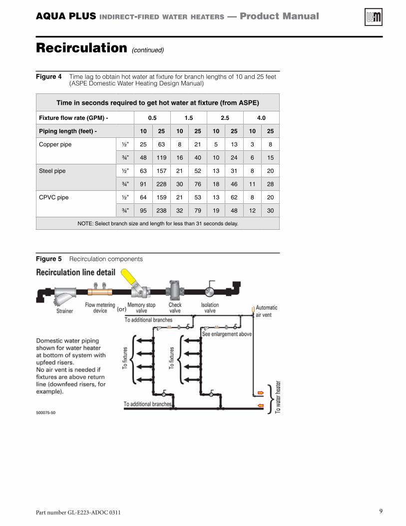
Figure 4 Time lag to obtain hot water at fixture for branch lengths of 10 and 25 feet (ASPE Domestic Water Heating Design Manual)
Time in seconds required to get hot water at fixture (from ASPE)
Fixture flow rate (GPM) - 0.5 1.5 2.5 4.0
Piping length (feet) - 10 25 10 25 10 25 10 25
Copper pipe ½” 25 63 8 21 5 13 3 8
¾” 48 119 16 40 10 24 6 15
Steel pipe ½” 63 157 21 52 13 31 8 20
¾” 91 228 30 76 18 46 11 28
CPVC pipe ½” 64 159 21 53 13 62 8 20
¾” 95 238 32 79 19 48 12 30
NOTE: Select branch size and length for less than 31 seconds delay.
Figure 5 Recirculation components
PartnumberGL-E223-ADOC0311 9

AQUA PLUS indirect-fired water heaters — Product Manual
Recirculation (continued)
Components
Circulator (Figure 6, item 1)
1. Littleflowisrequiredtomaintainatemperatureinthepiping.
2. Sizeofcirculatordependsonminimumflowre-quirementsofthetemperingvalve.
3. Minimumflowratesofthetemperingvalvemustbemaintained.
Aquastat (Figure 6, item 2)
1. Usedtocontroltheon-offpositionofthecircula-tor.Aquastatisset5°to10°lowerthanmixedwateroutletofthemixingvalve(#7).
2. Thecirculatorcannotruncontinuouslyasbypassthroughthemixingvalvewilleventuallyallowthetemperatureon thepiping toclimbto thewaterheatertemperatureduringdrawperiods.
Check valves (Figure 6, items 3–6)
1. Assuretheflowofwaterinonedirection.
2. Eachcheckvalvefunctionsasfollows:
a. #3and#4preventbypassintheeventofpres-suredrop.
b. #5preventsthermalsiphoningofhotwatertothecoldwatersupply.
c. #6preventsflowofcoldwatertothetemperedwater supply.A draw of tempered water willnotresultinflowofcoldwaterintothereturnloop.
Operation
1. Duringperiodofnormaluse(fixtureson)—Cir-culatorisoff.Thereisnoflowthrough#6,thereisflowthrough#5equaltotheflowatthefixtures,there isflowthrough#3and/or#4equaltoflowatfixture.
2. Whenallfixturesareoff—Circulatorisoff.Thereisnoflowthrough#3,#4,#5or#6.Watertemperatureinpipingiscooling.
3. Whentemperatureataquastat#2falls10°belowtemperaturetobemaintained—Circulatorison.There isflowthrough#6equal to theminimumrequiredbythemixingvalve,flowthrough#3and#4 equals the flow of the circulator. There is noflowthrough#5.
4. Aquastatreachestemperature—Circulatorisoff.Thereisnoflowthrough#3,#4,#5or#6.
Figure 6 Recirculation piping
Potential problems
1. Missing check valves #3 or #4 — Extreme pressure drop can causereverseflowofwater;hottocoldsupplyorcoldtohotsupply.
2. Missingcheckvalve#5—Hotwatercanmigratefromthewaterheaterbackthroughthecoldwatersupply.
3. Missingcheckvalve#6—Coldwatercanbeforcedbackthroughthetemperedwatersupplywhenafixtureisopened.
4. No aquastat #2 — Circulator runs continuously. Small amount ofwaterwillpassthroughmixingvalve.Eventuallyallhotwaterisflow-ing through valve. Recirculated water through cold port, hot waterthroughhotport.
5. Circulatortoosmall—Mixingvalveperformanceerratic.
PartnumberGL-E223-ADOC031110

AQUA PLUS indirect-fired water heaters — Product Manual
Figure 7 Zoning with circulators — direct-connected system piping
Notes
• Placecirculatorsatbegin-nings of zones. Placingthemattheendsofzonescouldresultinheatingidlezones.
• Size manifold piping fortotal flow of all zone cir-culators.
• Locate flow/check valvesascloseaspossibletowaterheaterboilersideconnec-tions—toreduceheatlossbetweencycles.
Wiring
• WMCR zone controller,optional priority — Fig-ure18,page21.
1. Thisdrawingisconceptualonly.Itshowsrepresenta-tive piping componentsand layout.Weil-McLaindoesnotrepresentthatthisdrawingmeetsanypartic-ularmechanicalorbuild-ingcodes.Theinstallerisresponsible for inclusionof all required safety de-vices, or other miscella-neouspipinghardwarenotshown on drawing. Theinstallerisresponsibleforpropersizing/selectionofallhardwareshownonthisdiagram.
2. Seeboilermanualforspe-cific details on installingtheboiler.
GV90+ or Ultra gas boilers:
Do NoTapplythedrawingsinthismanual.Referonlytotheboilermanual.
Recommended flow rate and minimum boiler-side pipe size
Heater model GPM Pipe
sizeHeater model GPM Pipe
size
35 8 1” 85 14 1¼” *
45 8 1” 105 14 1¼” *
55 8 1” Requires 1¼”x1” reducers at water heater
Boiler-side piping
PartnumberGL-E223-ADOC0311 11
AQUA PLUS indirect-fired water heaters — Product Manual
Boiler-side piping (continued)
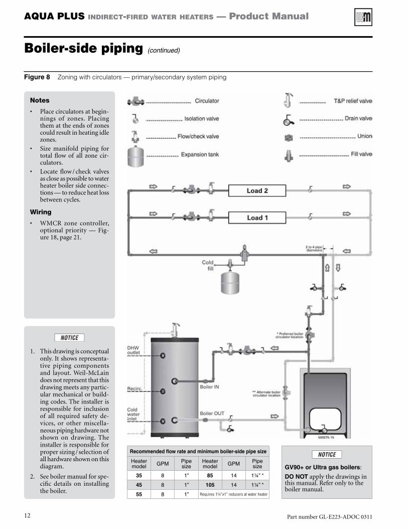
Figure 8 Zoning with circulators — primary/secondary system piping
Notes
• Placecirculatorsatbegin-nings of zones. Placingthemattheendsofzonescouldresultinheatingidlezones.
• Size manifold piping fortotal flow of all zone cir-culators.
• Locate flow/check valvesascloseaspossibletowaterheaterboilersideconnec-tions—toreduceheatlossbetweencycles.
Wiring
• WMCR zone controller,optional priority — Fig-ure18,page21.
1. Thisdrawingisconceptualonly.Itshowsrepresenta-tive piping componentsand layout.Weil-McLaindoesnotrepresentthatthisdrawingmeetsanypartic-ularmechanicalorbuild-ingcodes.Theinstallerisresponsible for inclusionof all required safety de-vices, or other miscella-neouspipinghardwarenotshown on drawing. Theinstallerisresponsibleforpropersizing/selectionofallhardwareshownonthisdiagram.
2. Seeboilermanualforspe-cific details on installingtheboiler.
GV90+ or Ultra gas boilers:
Do NoTapplythedrawingsinthismanual.Referonlytotheboilermanual.
Recommended flow rate and minimum boiler-side pipe size
Heater model GPM Pipe
sizeHeater model GPM Pipe
size
35 8 1” 85 14 1¼” *
45 8 1” 105 14 1¼” *
55 8 1” Requires 1¼”x1” reducers at water heater
PartnumberGL-E223-ADOC031112
AQUA PLUS indirect-fired water heaters — Product Manual
Boiler-side piping (continued)
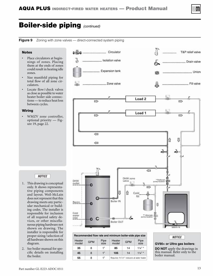
Figure 9 Zoning with zone valves — direct-connected system piping
Notes
• Placecirculatorsatbegin-nings of zones. Placingthemattheendsofzonescouldresultinheatingidlezones.
• Size manifold piping fortotal flow of all zone cir-culators.
• Locate flow/check valvesascloseaspossibletowaterheaterboilersideconnec-tions—toreduceheatlossbetweencycles.
Wiring
• WMZV zone controller,optional priority — Fig-ure19,page22.
1. Thisdrawingisconceptualonly.Itshowsrepresenta-tive piping componentsand layout.Weil-McLaindoesnotrepresentthatthisdrawingmeetsanypartic-ularmechanicalorbuild-ingcodes.Theinstallerisresponsible for inclusionof all required safety de-vices, or other miscella-neouspipinghardwarenotshown on drawing. Theinstallerisresponsibleforpropersizing/selectionofallhardwareshownonthisdiagram.
2. Seeboilermanualforspe-cific details on installingtheboiler.
GV90+ or Ultra gas boilers:
Do NoTapplythedrawingsinthismanual.Referonlytotheboilermanual.
Recommended flow rate and minimum boiler-side pipe size
Heater model GPM Pipe
sizeHeater model GPM Pipe
size
35 8 1” 85 14 1¼” *
45 8 1” 105 14 1¼” *
55 8 1” Requires 1¼”x1” reducers at water heater
PartnumberGL-E223-ADOC0311 13

AQUA PLUS indirect-fired water heaters — Product Manual
Boiler-side piping (continued)
Figure 10 Zoning with zone valves — primary/secondary system piping
Notes
• Placecirculatorsatbegin-nings of zones. Placingthemattheendsofzonescouldresultinheatingidlezones.
• Size primary piping fortotal flow of all zone cir-culators.
• Locate flow/check valvesascloseaspossibletowaterheaterboilersideconnec-tions—toreduceheatlossbetweencycles.
Wiring
• WMZV zone controller,optional priority — Fig-ure19,page22.
1. Thisdrawingisconceptualonly.Itshowsrepresenta-tive piping componentsand layout.Weil-McLaindoesnotrepresentthatthisdrawingmeetsanypartic-ularmechanicalorbuild-ingcodes.Theinstallerisresponsible for inclusionof all required safety de-vices, or other miscella-neouspipinghardwarenotshown on drawing. Theinstallerisresponsibleforpropersizing/selectionofallhardwareshownonthisdiagram.
2. SeeBoilerManualforspe-cific details on installingtheboiler.
GV90+ or Ultra gas boilers:
Do NoTapplythedrawingsinthismanual.Referonlytotheboilermanual.
Recommended flow rate and minimum boiler-side pipe size
Heater model GPM Pipe
sizeHeater model GPM Pipe
size
35 8 1” 85 14 1¼” *
45 8 1” 105 14 1¼” *
55 8 1” Requires 1¼”x1” reducers at water heater
PartnumberGL-E223-ADOC031114
AQUA PLUS indirect-fired water heaters — Product Manual
Boiler-side piping (continued)
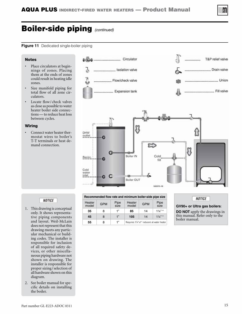
Figure 11 Dedicated single-boiler piping
Notes
• Placecirculatorsatbegin-nings of zones. Placingthemattheendsofzonescouldresultinheatingidlezones.
• Size manifold piping fortotal flow of all zone cir-culators.
• Locate flow/check valvesascloseaspossibletowaterheaterboilersideconnec-tions—toreduceheatlossbetweencycles.
Wiring
• Connectwaterheaterther-mostat wires to boiler’sT-Tterminalsorheatde-mandconnection.
1. Thisdrawingisconceptualonly.Itshowsrepresenta-tive piping componentsand layout.Weil-McLaindoesnotrepresentthatthisdrawingmeetsanypartic-ularmechanicalorbuild-ingcodes.Theinstallerisresponsible for inclusionof all required safety de-vices, or other miscella-neouspipinghardwarenotshown on drawing. Theinstallerisresponsibleforpropersizing/selectionofallhardwareshownonthisdiagram.
2. Seeboilermanualforspe-cific details on installingtheboiler.
GV90+ or Ultra gas boilers:
Do NoTapplythedrawingsinthismanual.Referonlytotheboilermanual.
Recommended flow rate and minimum boiler-side pipe size
Heater model GPM Pipe
sizeHeater model GPM Pipe
size
35 8 1” 85 14 1¼” *
45 8 1” 105 14 1¼” *
55 8 1” Requires 1¼”x1” reducers at water heater
PartnumberGL-E223-ADOC0311 15
AQUA PLUS indirect-fired water heaters — Product Manual
Boiler-side piping (continued)
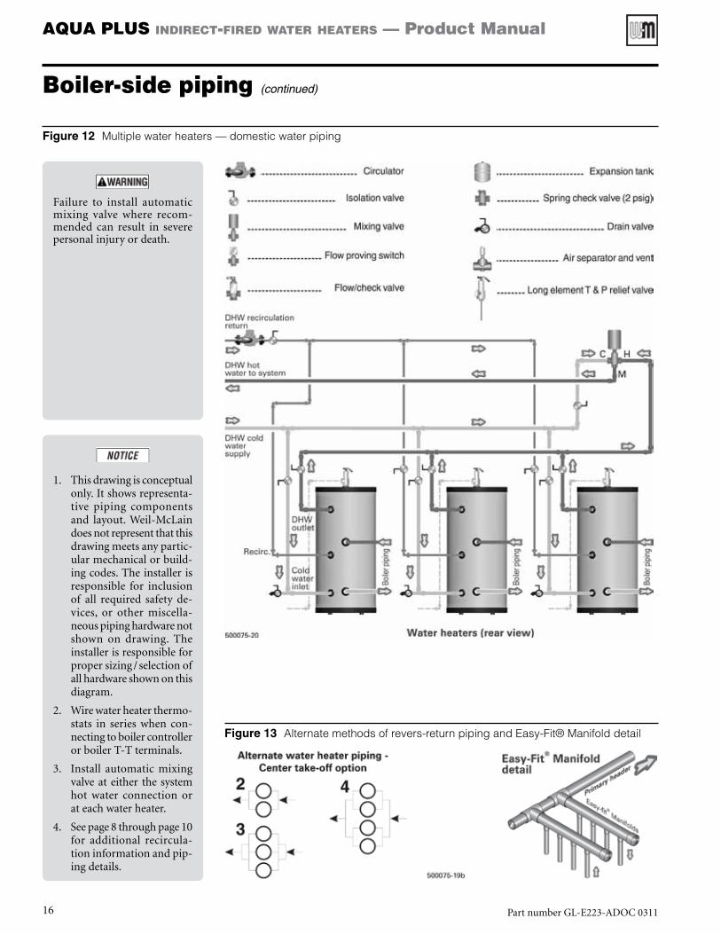
Figure 12 Multiple water heaters — domestic water piping
Figure 13 Alternate methods of revers-return piping and Easy-Fit® Manifold detail
Failure to install automaticmixing valve where recom-mended can result in severepersonalinjuryordeath.
1. Thisdrawingisconceptualonly.Itshowsrepresenta-tive piping componentsand layout.Weil-McLaindoesnotrepresentthatthisdrawingmeetsanypartic-ularmechanicalorbuild-ingcodes.Theinstallerisresponsible for inclusionof all required safety de-vices, or other miscella-neouspipinghardwarenotshown on drawing. Theinstallerisresponsibleforpropersizing/selectionofallhardwareshownonthisdiagram.
2. Wirewaterheaterthermo-stats in series when con-nectingtoboilercontrollerorboilerT-Tterminals.
3. Install automatic mixingvalveateither thesystemhot water connection orateachwaterheater.
4. Seepage8throughpage10for additional recircula-tioninformationandpip-ingdetails.
PartnumberGL-E223-ADOC031116

AQUA PLUS indirect-fired water heaters — Product Manual
Boiler-side piping (continued)
Figure 14 Multiple water heaters and dedicated multiple boilers — boiler water piping
Notes
• See legend and details inFigure12,page16.
1. Thisdrawingisconceptualonly.Itshowsrepresenta-tive piping componentsand layout.Weil-McLaindoesnotrepresentthatthisdrawingmeetsanypartic-ularmechanicalorbuild-ingcodes.Theinstallerisresponsible for inclusionof all required safety de-vices, or other miscella-neouspipinghardwarenotshown on drawing. Theinstallerisresponsibleforpropersizing/selectionofallhardwareshownonthisdiagram.
2. Seeboilermanualforspe-cific details on installingtheboiler.
GV90+ or Ultra gas boilers:
Do NoTapplythedrawingsinthismanual.Referonlytotheboilermanual.
PartnumberGL-E223-ADOC0311 17
AQUA PLUS indirect-fired water heaters — Product Manual
Connecting to a low-pressure steam boiler
Special considerationsWhendesigningsteamanddomestichotwatersystems,therearesomekeyissuesthatmustbetakenintoconsiderationduringtheinitialde-signphase.Bydesigningthesystemproperlyfromthestart,youcanavoidproblemsandhaveahotwaterloopinasteamboilersystem.
• The domestic water demand should preferably not exceed 1/3ofthesteamboilercapacity.Largerdemandmaycausedifficultyobtainingsteamasneeded.
• Keepthelooptemperaturebelowtheflashpoint.Flashingcanresultinnoiseandcirculatordamageorshortenedlife.
• Besuretheloopiscompletelyclosed,withnoautomaticormanualairvents,oranythingthatcouldallowairtoenterthesystemwhenthepumpshutsoff.
• Pipe supply fromone sideof theboiler, return to theoppositesideasshown.
• Supplyfromatappingthatishighenoughtopreventintroducingsedimentintothepipingandcirculatoryetstillbelowthewaterline.Avoidthemudlegoftheboiler.
• Useanallbronzecirculator.• Avoid wet rotor circulators. Select a circulator with a large
volute,suchasatypical3-piececirculator.• Thiswillreducecloggingandwillresistthecorrosionpotential
fromthesteamcondensate.
• Makesurethecirculatorisproperlysized.Ifthecirculatorrunstoofaroutonitscurve,cavitationpotentialincreasessignificantly.
• Use(2)flow/checkvalvesas showntoreduce thepotential forgravitycirculation.• DO NOT use spring-loaded check valves in place of the
flow/checkvalvesshowninFigure16,page19.
Installation and start-up of water heaters connected to steam boilers1. SeeFigure16,page19,forsuggestedpipingschematic.
2. Pipethedomesticwaterconnectionstothewaterheaterper“Do-mesticwaterpiping,”page6.
Boilerconnectionsforthewaterheatermustbebelowthewaterline.DONOTusethegaugeglasstappingoralowwatercut-offtappingifaLWCOisinstalledthere.
Forsteampiping,refertothesteamboilermanual.
DONOTinstallanairventanywhereinthepiping.Thepipingmustbeairtight.
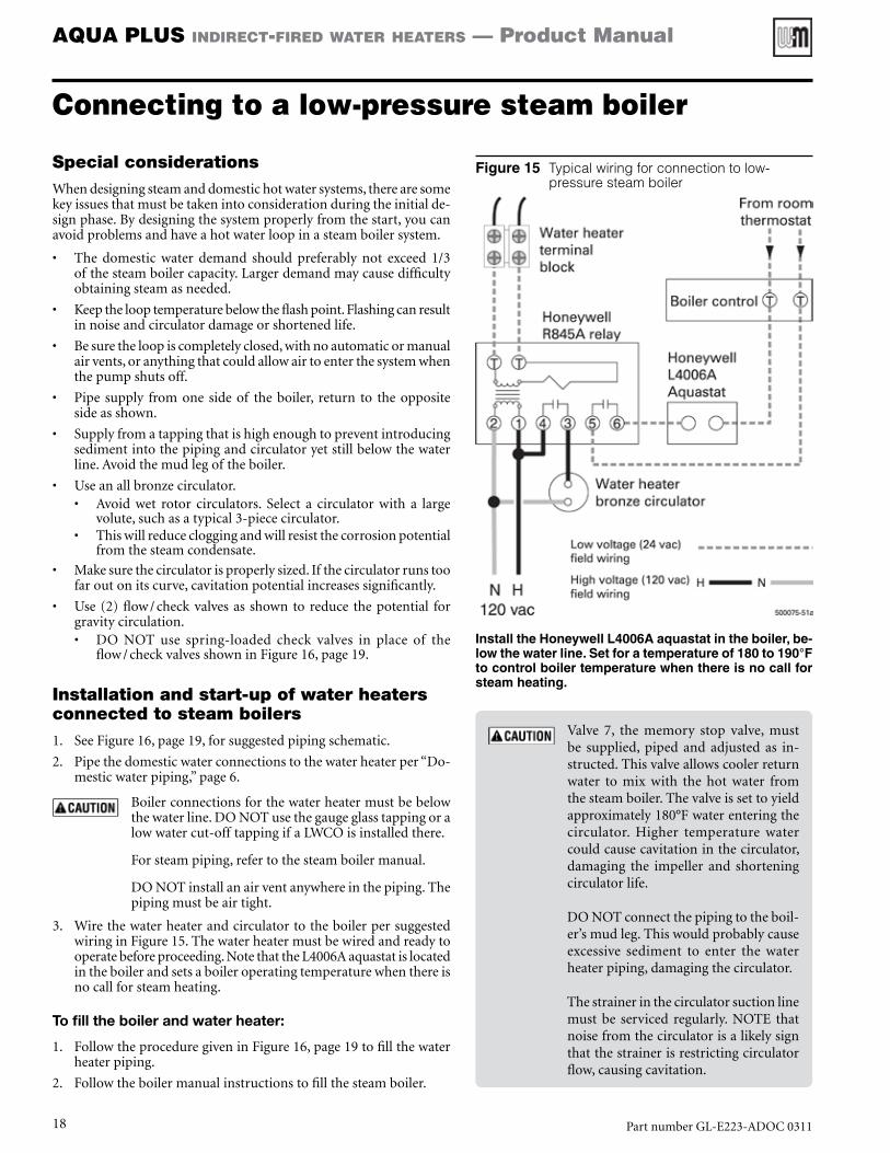
3. WirethewaterheaterandcirculatortotheboilerpersuggestedwiringinFigure15.Thewaterheatermustbewiredandreadytooperatebeforeproceeding.NotethattheL4006Aaquastatislocatedintheboilerandsetsaboileroperatingtemperaturewhenthereisnocallforsteamheating.
To fill the boiler and water heater:
1. FollowtheproceduregiveninFigure16,page19tofillthewaterheaterpiping.
2. Followtheboilermanualinstructionstofillthesteamboiler.
Figure 15 Typical wiring for connection to low-pressure steam boiler
Install the Honeywell L4006A aquastat in the boiler, be-low the water line. Set for a temperature of 180 to 190°F to control boiler temperature when there is no call for steam heating.
Valve 7, the memory stop valve, mustbe supplied, piped and adjusted as in-structed.Thisvalveallowscoolerreturnwater to mix with the hot water fromthesteamboiler.Thevalveissettoyieldapproximately180°Fwaterenteringthecirculator. Higher temperature watercouldcausecavitationinthecirculator,damaging the impeller and shorteningcirculatorlife.
DONOTconnectthepipingtotheboil-er’smudleg.Thiswouldprobablycauseexcessive sediment to enter the waterheaterpiping,damagingthecirculator.
Thestrainerinthecirculatorsuctionlinemust be serviced regularly. NOTE thatnoisefromthecirculatorisalikelysignthatthestrainerisrestrictingcirculatorflow,causingcavitation.
PartnumberGL-E223-ADOC031118

AQUA PLUS indirect-fired water heaters — Product Manual
Connecting to a low-pressure steam boiler (continued)
Figure 16 Low pressure steam boiler application — Domestic water heating using water pumped from steam boiler
Notes
• Locateflow/checkvalveascloseaspossible towaterheaterboilersideconnec-tions—toreduceheatlossbetweencycles.
Use memory stop valve7 toblend some of the water re-turningtotheboilerwiththehot water coming from theboiler. This will reduce thepossibilityofflashing(cavita-tion)inthecirculator.Slowlyopenvalve7untiltemperaturegauge8reads200°F.
Setthememorystoponvalve7afteradjusting.Attachatagtothevalvewarningnotocloseorchangevalveposition.
NOTE—If the boiler water level should drop below ei-ther the water heater boiler water supply or return line, the filling procedure will have to be repeated.
1. Thisdrawingisconceptualonly.Itshowsrepresenta-tive piping componentsand layout.Weil-McLaindoesnotrepresentthatthisdrawingmeetsanypartic-ularmechanicalorbuild-ingcodes.Theinstallerisresponsible for inclusionof all required safety de-vices, or other miscella-neouspipinghardwarenotshown on drawing. Theinstallerisresponsibleforpropersizing/selectionofallhardwareshownonthisdiagram.
2. Seeboilermanualforspe-cific details on installingtheboiler.
Filling the piping1. Parts of the boiler water piping to the
waterheatermaybehigherthanthewa-terline,dependingontheheightofthewater heater boiler supply connection.Thepipingmustbeairtighttopreventairfrompocketingatthetopofthepiping,stoppingflow.
2. TheboilerMUSTbefilledandreadytooperate before proceeding. Follow theboilermanualtofilltheboiler.
3. Follow the procedure below to fill theboiler-to-water heater piping. See Fig-ure16.
Step 1 Closeisolationvalves5and6toisolatetheboiler.
Step 2 Closevalve3andopenvalve4.Con-nect a cold water supply hose tovalve3.Connectahosefromvalve4toadrainablelocation.
Step 3 Closevalve10.Openvalve7.
Step 4 Openvalve3.Waterwillflowthroughvalve 7 and out through valve 4 todrain.Letwater rununtil all airhasbeen removed from the line. Closevalve4.Thenclosevalve3.
Step 5 Closevalve7.Thenopenvalve10.
Step 6 Openvalve3.Waterwillflowthroughthe circulator line, the water heatercoil and the return piping, then outthroughvalve4todrain.Letwaterrununtilallairhasbeenremovedfromtheline.Closevalve4.Thenclosevalve3.Removehoses.
Step 7 Follow the instructions in“Waterheater filling and start-up,” page 23,tofill thedomesticwatersideof thewaterheater.
Step 8 Open valve 7 about ¼ turn for aninitialsetting.
Step 9 Open isolation valves 5and 6. Makesure the boiler water level is correctpertheboilermanual.
Step 10 Starttheboilerperinstructionsgivenintheboilermanual.Allowboilertobeginsteaming.
Step 11 StarttheDHWcirculator.Watchthetemperatureatgauge8.Adjustvalve7untilgauge8readsabout180°Fwithsystematsteadyoperation.
Step 12 Continue checking under varyingDHW demand conditions to ensuresystemwilloperateasrequired.
PartnumberGL-E223-ADOC0311 19

AQUA PLUS indirect-fired water heaters — Product Manual
Boiler-side wiring and controls
Electrical shock hazard—Cancauseseverepersonal
injury,deathorsubstantialpropertydamage.Disconnect
powerbeforeinstallingand/orservicing.
Wiring requirements1. Allwiringmustbeaminimumof18gaugeandinstalledinaccordance
with:• U.S.A.—NationalElectricalCodeandanyothernational,stateor
localcoderequirementshavingjurisdiction.• Canada—CSAC22.1CanadianElectricalCodePart1andany
other national, provincial and local code requirements havingjurisdiction.
2. Iforiginalwireassuppliedwithappliancemustbereplaced,Type90°Coritsequivalentmustbeused.
3. Refertocontrolcomponent instructionspackedwithboiler forap-plicationinformation.
4. Anoptional service switchmaybe installed inwaterheater electri-calcircuit.Thisswitchwouldonlyshutoffthewaterheater,notthehomeheatingsystem.Donotshutoffwaterheaterifthereisachanceoffreezing.
5. Allelectricalcontactsareshownwithnopowerapplied—off-the-shelfcondition.
Circulators1. Sizepriorityrelayfortotalampdrawofallcirculators.
Zone Valves1. Sizetransformerformaximumloadofallzonevalves.
Wiring to the water heater1. Fieldconnectionstothewaterheaterthermostatarefor24VAConly,
connectingtothetwo-poleterminalblockshowninFigure17.
Wiring options1. ThismanualshowswiringonlyforuseofWeil-McLainWMCRCir-
culator Zone Controller orWeil-McLainWMZV ZoneValve ZoneController.
2. Otherwiringmethodsmaybeacceptableandarelefttotheinstaller.
Use domestic priority1. When possible, set controls to provide domestic
priority — that is, on a call for domestic waterthecontrolswitchesfromspaceheatingtoDHWonly.
2. Domesticpriorityensuresthefastestpossiblere-sponsetotheDHWcallforheat.
3. Thesmallerthewaterheater,thegreatertheneedforrapidresponse.
Figure 17 Inspection hatch assembly (hatch cover shown transparent)
1 Temperatureadjustmentknob
2 Inspectionplate(handhole)
3 Factorywiresfromthermostattofieldwiringterminalblock
4 Fieldwiringterminalblock
5 M8hexnut
6 Inspectionplatebracket
PartnumberGL-E223-ADOC031120
AQUA PLUS indirect-fired water heaters — Product Manual
Wiring — zoning with circulators
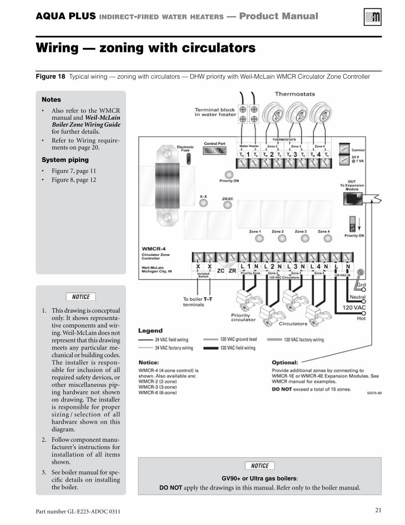
Notes
• Also refer to theWMCRmanualandWeil-McLain Boiler Zone Wiring Guideforfurtherdetails.
• Refer toWiring require-mentsonpage20.
System piping
• Figure7,page11
• Figure8,page12
1. Thisdrawingisconceptualonly.Itshowsrepresenta-tivecomponentsandwir-ing.Weil-McLaindoesnotrepresentthatthisdrawingmeets anyparticularme-chanicalorbuildingcodes.The installer is respon-sible for inclusion of allrequiredsafetydevices,orother miscellaneous pip-ing hardware not shownondrawing.The installeris responsible for propersizing/selection of allhardware shown on thisdiagram.
2. Followcomponentmanu-facturer’s instructions forinstallation of all itemsshown.
3. Seeboilermanualforspe-cific details on installingtheboiler.
Figure 18 Typical wiring — zoning with circulators — DHW priority with Weil-McLain WMCR Circulator Zone Controller
GV90+ or Ultra gas boilers:
Do NoTapplythedrawingsinthismanual.Referonlytotheboilermanual.
PartnumberGL-E223-ADOC0311 21

AQUA PLUS indirect-fired water heaters — Product Manual
Wiring — zoning with zone valves
Notes
• Also refer to theWMZVmanualandWeil-McLain Boiler Zone Wiring Guideforfurtherdetails.
• Refer toWiring require-mentsonpage20.
System piping
• Figure9,page13
• Figure10,page14
Installallzonevalvespervalvemanufacturer’sinstructions.
1. Thisdrawingisconceptualonly.Itshowsrepresenta-tivecomponentsandwir-ing.Weil-McLaindoesnotrepresentthatthisdrawingmeets anyparticularme-chanicalorbuildingcodes.The installer is respon-sible for inclusion of allrequiredsafetydevices,orother miscellaneous pip-ing hardware not shownondrawing.The installeris responsible for propersizing/selection of allhardware shown on thisdiagram.
2. Followcomponentmanu-facturer’s instructions forinstallation of all itemsshown.
3. Seeboilermanualforspe-cific details on installingtheboiler.
Figure 19 Typical wiring — zoning with zone valves — DHW priority with Weil-McLain WMZV Zone Valve Zone Controller
GV90+ or Ultra gas boilers:
Do NoTapplythedrawingsinthismanual.Referonlytotheboilermanual.
PartnumberGL-E223-ADOC031122

AQUA PLUS indirect-fired water heaters — Product Manual
Water heater filling and start-up
The installation and water chemistry must meet therequirementsbelow.Failuretocomplycouldresultindamage to the water heater, causing possible severepersonalinjury,deathorsubstantialpropertydamage.
Boiler water restrictions• Thoroughlyflush theboiler system(withoutwaterheatercon-
nected)toremovesediment.
• Thewaterheaterheatexchangercanbedamagedbybuild-uporcorrosionduetosediment.
• Boilerwater(includingadditives)mustbepracticallynon-toxic,havingtoxicityratingorclassof1,aslistedinClinicalToxicologyofCommercialProducts.
• Ifantifreezeisusedinboilersystem:• Localcodesmayrequireabackflowpreventeroncoldwater
supplyline.• Useantifreezespecificallyintendedforhydronicheatingsys-
tems.Inhibitedpropyleneglycolisrecommended.• Followboilermanualinstructionsforantifreezeusage.• Donotuseautomotive,ethyleneglycolorpetroleum-based
antifreeze.Donotuseanyundilutedantifreeze.
Maximum boiler-side flow rate• Selecttheboiler-sidecirculatorcarefully.Theflowratethroughthe
boilersideofthewaterheatermustnotexceedthevaluesbelow.HigherflowratescouldresultinaninputabovetheratingoftheT&Pvalve.
• Models AQUA PLUS-32, 42 and 52 — do not exceed 12 GPM.
• Models AQUA PLUS-80 and 105 — do not exceed 16 GPM.
Filling the domestic water tank1. Fillthedomesticwatertankwithfreshwaterthatmeetsthechemistry
requirementsabove.
2. Donotexceedafillpressureof70PSIG.
Whenthewatersupplypressureishigherthan70PSIG,makesure that a pressure-reducing valve is installed on the coldwatersupplylinetopreventleakagefromtheT&Preliefvalve.Athermalexpansiontankisalsorequired.
3. Ventthepipingasnecessarytoremoveanytrappedair.
Start-up and operation1. Followthe“Start-upchecklist,”page23toprepareforstart-up.
Start-up checklist
❏❏ Verify that T&P relief valve is properly installedandpipedasdirectedinthismanualandperlocalcoderequirements.
❏❏ VerifythattheDHWtankandboiler-sidepipingarecompleteandarefilledwithwaterandpres-surized.
❏❏ Verifythatallairhasbeenbledfrombothdomesticandboilerwatersystems.
❏❏ Verifythatcoldandhotwater linesarecorrectlyconnectedtodomesticwatersystem.
❏❏ Verifythatsupplyandreturnpipingfromboileriscorrectlyconnectedtowaterheater.
❏❏ Checkallfittingsandpipingforleaks.
❏❏ Verifythatallwiringisinstalledcorrectly.
❏❏ Set water heater thermostat according to systemrequirements.See“Waterheatertemperaturead-justment,”page24.
❏❏ StartboileraccordingtotheBoilerManual.
❏❏ Verifythattheboilerandwaterheaterareoperatingcorrectly, per“Water heater temperature adjust-ment,”page24.
❏❏ Reviewthefollowingsectionswiththehomeownerorsystemoperator:
• Water Heater Start-Up
• Adjusting Water Heater Temperature
• Water Heater Maintenance
PartnumberGL-E223-ADOC0311 23
AQUA PLUS indirect-fired water heaters — Product Manual
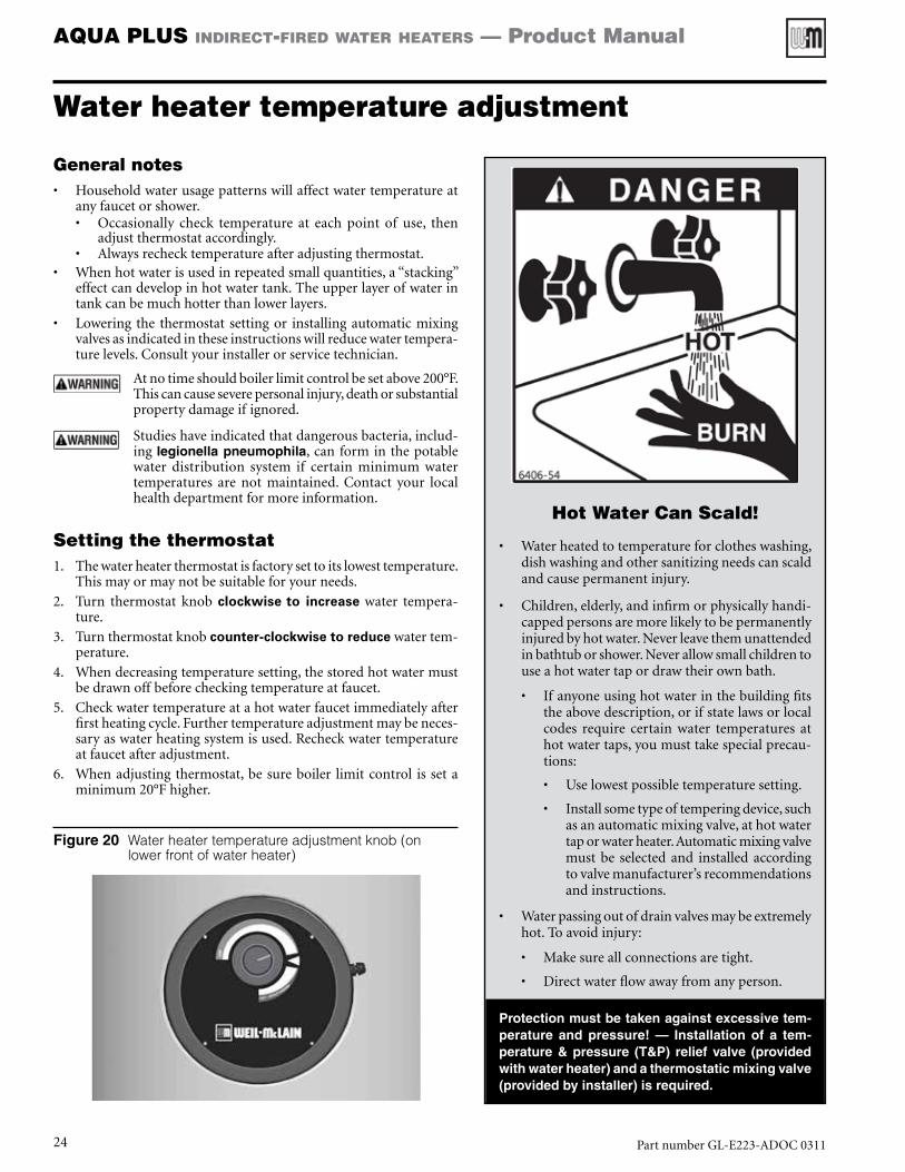
Hot Water Can Scald!
• Waterheatedtotemperatureforclotheswashing,dishwashingandothersanitizingneedscanscaldandcausepermanentinjury.
• Children,elderly,andinfirmorphysicallyhandi-cappedpersonsaremorelikelytobepermanentlyinjuredbyhotwater.Neverleavethemunattendedinbathtuborshower.Neverallowsmallchildrentouseahotwatertapordrawtheirownbath.
• Ifanyoneusinghotwaterinthebuildingfitstheabovedescription,orifstatelawsorlocalcodes require certain water temperatures athotwatertaps,youmusttakespecialprecau-tions:
• Uselowestpossibletemperaturesetting.
• Installsometypeoftemperingdevice,suchasanautomaticmixingvalve,athotwatertaporwaterheater.Automaticmixingvalvemustbe selectedand installedaccordingtovalvemanufacturer’srecommendationsandinstructions.
• Waterpassingoutofdrainvalvesmaybeextremelyhot.Toavoidinjury:
• Makesureallconnectionsaretight.
• Directwaterflowawayfromanyperson.
Protection must be taken against excessive tem-perature and pressure! — Installation of a tem-perature & pressure (T&P) relief valve (provided with water heater) and a thermostatic mixing valve (provided by installer) is required.
Water heater temperature adjustment
General notes • Householdwaterusagepatternswillaffectwatertemperatureat
anyfaucetorshower.• Occasionally check temperature at each point of use, then
adjustthermostataccordingly.• Alwaysrechecktemperatureafteradjustingthermostat.
• Whenhotwaterisusedinrepeatedsmallquantities,a“stacking”effectcandevelopinhotwatertank.Theupperlayerofwaterintankcanbemuchhotterthanlowerlayers.
• Lowering the thermostat settingor installingautomaticmixingvalvesasindicatedintheseinstructionswillreducewatertempera-turelevels.Consultyourinstallerorservicetechnician.
Atnotimeshouldboilerlimitcontrolbesetabove200°F.Thiscancauseseverepersonalinjury,deathorsubstantialpropertydamageifignored.
Studieshaveindicatedthatdangerousbacteria,includ-ing legionella pneumophila,canforminthepotablewater distribution system if certain minimum watertemperatures are not maintained. Contact your localhealthdepartmentformoreinformation.
Setting the thermostat1. Thewaterheaterthermostatisfactorysettoitslowesttemperature.
Thismayormaynotbesuitableforyourneeds.
2. Turn thermostat knob clockwise to increase water tempera-ture.
3. Turnthermostatknobcounter-clockwise to reducewatertem-perature.
4. Whendecreasingtemperaturesetting,thestoredhotwatermustbedrawnoffbeforecheckingtemperatureatfaucet.
5. Checkwatertemperatureatahotwaterfaucetimmediatelyafterfirstheatingcycle.Furthertemperatureadjustmentmaybeneces-saryaswaterheatingsystemisused.Recheckwatertemperatureatfaucetafteradjustment.
6. Whenadjustingthermostat,besureboiler limitcontrol issetaminimum20°Fhigher.
Figure 20 Water heater temperature adjustment knob (on lower front of water heater)
PartnumberGL-E223-ADOC031124

AQUA PLUS indirect-fired water heaters — Product Manual
Water heater maintenance
Boilerwater—readandcomplywithallrequirementsunder“Boilerwaterrestrictions,”page3.
Waterfromopeneddrainvalves,unionsandotherconnec-tionsmaybeextremelyhot.Toavoidseverepersonalinjury,deathorsubstantialpropertydamage:
• Tightenalldrainhoseconnections.• Directhotwaterawayfromallpersons.
ATTENTION USER!
Have the water heater serviced at least once an-nually byaqualifiedservicetechnician.
Followthemaintenance proceduresbelowatleastmonthly.
Read“Waterheatertemperatureadjustment,”page24.
Failuretocomplywiththeabovecanresultinseverepersonalinjury,deathorsubstantialpropertydam-age.
MONTHLY maintenance by user
• AtleastMoNTHLY,visuallycheckvalves,pipesandfittingsforleaks.
• Check hot water supply at several outlets. Make sure watertemperatureisnottoohot.
• Call qualified service technician to repair leaks or addressproblems.
MONTHLY maintenance by user• AtleastMONTHLY,visuallycheckvalves,pipesandfittingsforleaks.
• Checkhotwatersupplyatseveraloutlets.Makesurewatertemperatureisnottoohot.
• Callqualifiedservicetechniciantorepairleaksoraddressproblems.
ANNUAL start-up by qualified service technician
ObtainanInspectionandservicekit(see“Replacementparts,”page39)beforeattemptingtoperformtheannualstart-up.Thiskitcontainsitemsthatwillusuallyhavetobereplaced.
Checkwatersupplytemperatureatseveraloutletstoensurethe water temperature is acceptable for intended use andthatalltemperaturecontroldevicesarefunctioningproperly.Readpage3andverifythatallrequirementsaremetbytheinstallation.
Perform the following procedures:
❏❏ Performanyproceduresrequiredbylocalcodes.
❏❏ Verifysystempressurebothondomesticwaterandboilerwatersides.
❏❏ Manually operate T&P relief valve at least onceayear(seeFigure21).Thiswillreleasesomehotwater.Moveoperatinglevertoopenpositionforafewsecondsandthenmoveitback,allowingittosnapclosed.AfterT&Preliefvalveisoperated,if it continues to release water, close cold waterinlettowaterheaterimmediately.Followdraininginstructions, and replace the T&P relief valve. IfT&Preliefvalveweepsperiodically,itmaybeduetothermalexpansion.Installanexpansiontankifnotalreadyinstalled.
❏❏ Follow instructions on circulator to oil it, ifoil-lubricated.
❏❏ Follow instructions in“Inspect anode and waterheaterinterior,”page26.
❏❏ Checkvalves,pipesandfittingsforleaks.
❏❏ Checkfunctionofallcontrolsandvalves(seecon-trolmanufacturer’sinstructions).
❏❏ Reviewhomeowner’smaintenanceresponsibilities
Figure 21 T&P valve operation
Before operating the T&P reliefvalve,makesurenooneisinfrontoforaroundtheT&Preliefvalvedis-chargepiping.Hotdischargewatercancauseseverepersonalinjuryorsubstantialpropertydamage.
Plugging T&P relief valve or dis-charge piping can cause excessivepressureinthewaterheater,result-inginseverepersonalinjury,deathorsubstantialpropertydamage.
PartnumberGL-E223-ADOC0311 25

AQUA PLUS indirect-fired water heaters — Product Manual
Water heater maintenance (continued)
and their frequencies, including any not listed in the followingparagraphs. Figure 22 Inspection hatch assembly (hatch cover
shown transparent)
1 Temperatureadjustmentknob
2 Inspectionplate(handhole)
3 Factorywiresfromthermostattofieldwiringterminalblock
4 Fieldwiringterminalblock
5 M8hexnut
6 Inspectionplatebracket
Thepurposeofthemagnesium anodeistoreducethedamagingeffectsofaggressivewateronthewa-terheater.Aggressivewaterwillcausetheanodetoerode.
Theanodemustbeinspectedatleastannuallytode-terminewhetheranewanodeshouldbeinstalled.
Severeorrapiddeteriorationoftheanodeindicatesveryaggressivewater.Ifthisoccurs,havethewatertestedtoverifywhetheritiswithinthelimitsgivenunder“Operatingrestrictions,”page3.
Failuretoinspecttheanoderegularlyandreplaceifnecessarycouldresultindamagetothewaterheater,causing possible severe personal injury, death orsubstantialpropertydamage.
Inspect anode and water heater interior1. Closedomesticwaterisolationvalves.
2. Drainthewaterheatercompletelyandallowittocooloff.
3. Removetheinspectionhatchcover(Figure24,page39,item8).a. Thetemperaturecontrolbulbwillhavetobepulledoutofthe
immersionwell,locatedintheinspectionplate.
4. Afterthewaterheaterhasdrainedandcooled,removetheinspec-tionplate(Figure22,page26,item2).
Therewillbesomewaterremaininginthebottomofthewaterheater.Thiscanbesiphonedofforremovedwithawet/dryvacuum.
a. PartiallyunscrewtheM8hexnut(Figure22,page26,item5)whileholding thebracket (Figure22,page26, item6).DONOTcompletelyremovethenut.
b. Holdandturnthebracket90degrees,beingcarefulnottodroptheinspectionplateinsidethetank.
c. Removetheinspectionplate.
5. Useaworklightorflashlighttoinspecttheinteriorofthetank.
6. Useaplasticscraperifneededtoremoveanyaccumulationonthecoil.DONOTuseabrasivesormetallicobjects.
7. Remove as much sediment as possible through the inspectionopening.
8. Rinse the bottom and remove remainder with a wet/dry shopvacuum.
9. Removethemagnesiumanodecoverandanode(Figure24,page39,items10and1).
10. Inspect the anode and replace if needed with part list in (Fig-ure24,page39).SeeWARNINGabove.
11.Replacetheinspectionplategasketifnecessary.Thenre-installtheinspectionplate.Alignthegasketcarefully.DONOTover-tightenthebolt.Thiscoulddamageorextrudethegasket,ordistorttheplate.
12.Re-installtheaccesscoverhatchandtightenthefourM8Phillips-headscrews.Donotover-tightenthescrews.
13.Refillthewaterheaterandrestoretooperation.
14.Verifyoperationofboilerandwaterheater.
Drain the water heater if necessary during shutdown periods1. Drainthewaterheaterifitwillbeshutoffandexposed
to freezing temperatures. Freezing water will expandandmaydamagewaterheater.a. Ifboilerwatercontains sufficientantifreeze, then
onlythedomesticwaterneedstobedrained.b. Ifboilerwaterdoesnotcontainsufficientantifreeze,
thentheboilerwaterandthedomesticwatermustbedrained.
PartnumberGL-E223-ADOC031126
AQUA PLUS indirect-fired water heaters — Product Manual
Troubleshooting
Preparation for troubleshooting
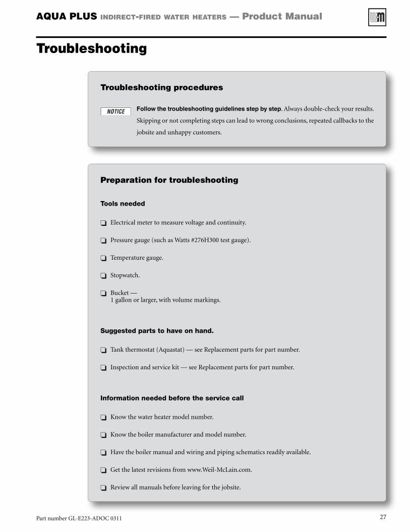
Tools needed
❏❏ Electricalmetertomeasurevoltageandcontinuity.
❏❏ Pressuregauge(suchasWatts#276H300testgauge).
❏❏ Temperaturegauge.
❏❏ Stopwatch.
❏❏ Bucket—1gallonorlarger,withvolumemarkings.
Suggested parts to have on hand.
❏❏ Tankthermostat(Aquastat)—seeReplacementpartsforpartnumber.
❏❏ Inspectionandservicekit—seeReplacementpartsforpartnumber.
Information needed before the service call
❏❏ Knowthewaterheatermodelnumber.
❏❏ Knowtheboilermanufacturerandmodelnumber.
❏❏ Havetheboilermanualandwiringandpipingschematicsreadilyavailable.
❏❏ Getthelatestrevisionsfromwww.Weil-McLain.com.
❏❏ Reviewallmanualsbeforeleavingforthejobsite.
Troubleshooting procedures
Follow the troubleshooting guidelines step by step.Alwaysdouble-checkyourresults.
Skippingornotcompletingstepscanleadtowrongconclusions,repeatedcallbackstothe
jobsiteandunhappycustomers.
PartnumberGL-E223-ADOC0311 27
AQUA PLUS indirect-fired water heaters — Product Manual
Troubleshooting (continued)
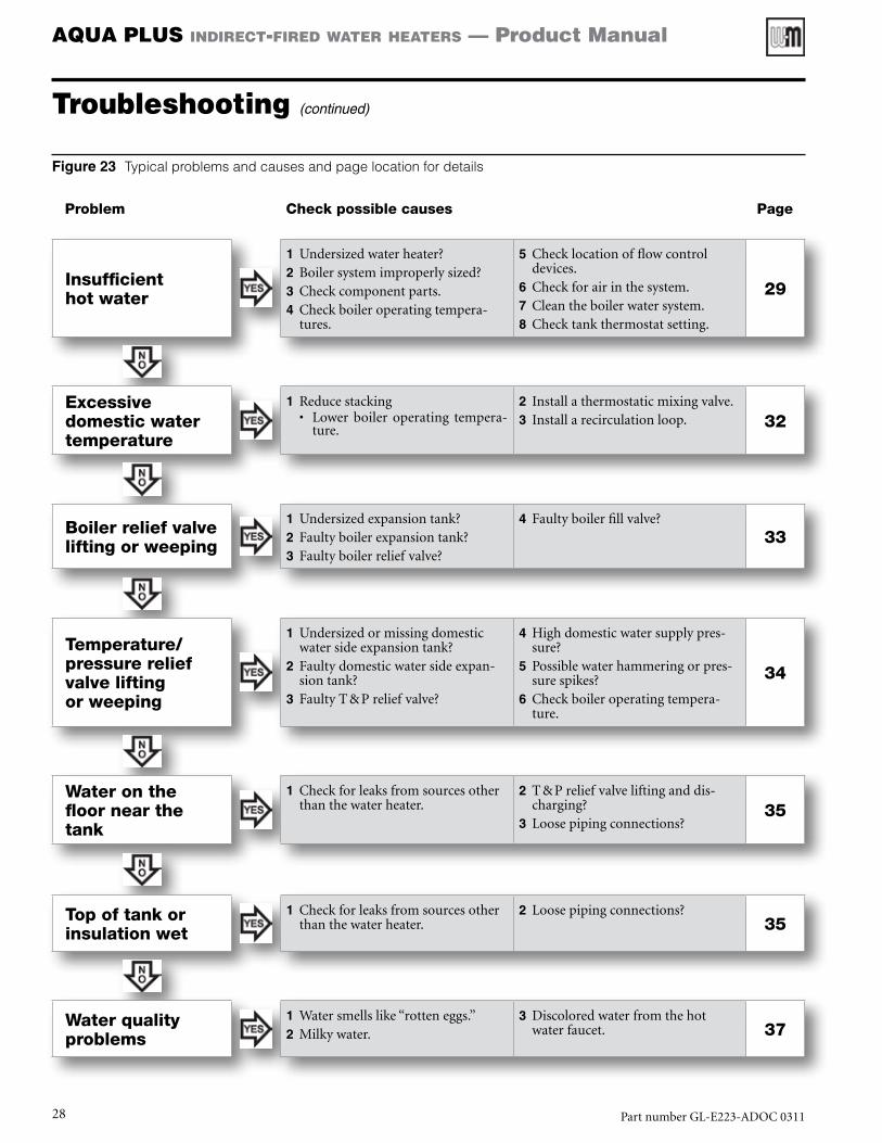
Insufficient hot water
1 Undersizedwaterheater?2 Boilersystemimproperlysized?3 Checkcomponentparts.4 Checkboileroperatingtempera-
tures.
5 Checklocationofflowcontroldevices.
6 Checkforairinthesystem.7 Cleantheboilerwatersystem.8 Checktankthermostatsetting.
29
Excessive domestic water temperature
1 Reducestacking• Lower boiler operating tempera-
ture.
2 Installathermostaticmixingvalve.3 Installarecirculationloop. 32
Boiler relief valve lifting or weeping
1 Undersizedexpansiontank?2 Faultyboilerexpansiontank?3 Faultyboilerreliefvalve?
4 Faultyboilerfillvalve?
33
Temperature/pressure relief valve lifting or weeping
1 Undersizedormissingdomesticwatersideexpansiontank?
2 Faultydomesticwatersideexpan-siontank?
3 FaultyT&Preliefvalve?
4 Highdomesticwatersupplypres-sure?
5 Possiblewaterhammeringorpres-surespikes?
6 Checkboileroperatingtempera-ture.
34
Water on the floor near the tank
1 Checkforleaksfromsourcesotherthanthewaterheater.
2 T&Preliefvalveliftinganddis-charging?
3 Loosepipingconnections?35
Top of tank or insulation wet
1 Checkforleaksfromsourcesotherthanthewaterheater.
2 Loosepipingconnections?35
Water quality problems
1 Watersmellslike“rotteneggs.”2 Milkywater.
3 Discoloredwaterfromthehotwaterfaucet. 37
Figure 23 Typical problems and causes and page location for details
Problem Check possible causes Page
PartnumberGL-E223-ADOC031128

AQUA PLUS indirect-fired water heaters — Product Manual
Troubleshooting (continued)
1 Undersized water heater?
• Therearemanymethodsofsizingvariousapplications,i.e.ASHRAEsizingtablesorASPEdomesticwaterheatingdesignmanual.• Confirmthewaterdemandrequiredfortheapplication.
• Confirmtheflowratesofthefixtures.• Forexample,wasthetanksizedforshowerheadsat2.0gpm,whiletheactualheadsare5.0gpm?• Useabucketandastopwatchtodeterminefixtureflowrates.
• Evaluatethehotwaterusagepatternforaday.• Isthepeakdemandunusuallyhighfortheapplication?
• Hasthedemandfordomestichotwaterchangedsincethesystemwasinstalled?• Abathroomremodelingprojectwithanewly installedwhirlpooltubwillsubstantiallychangethe
domesticwaterdemand.
2 Boiler system improperly sized?
• Cantheboilerprovidetherequiredoutputtomeetthedomesticwaterload?Determinetheboilerdomesticwatercapacity,GPH,bythefollowing:
Boiler DHW capacity, GPH =Boiler output Btuh
Temp. rise °F x 8.33
[Temp. rise °F = Required DHW temp. °F – Incoming temp. °F]
[8.33 = Density of water (lbs/gal) x 1 Btu / lb-°F]
• Example—Asinglefamilyhomewitha3.0GPMshowerfixtureanda150,000Btuhoutputboilerca-pacity.• Theshowerdemandof3.0GPMequals180GPH(60timestheGPM).• Istheboilercapacityenoughtodeliverthishotwaterflowat115°Fforanextendedperiod?Determine
theboilercapacity:
Boiler DHW capacity, GPH =150,000 Btuh
(115°F – 50°F) x 8.33= 277 GPH
• Theboileriscapableofdelivering277GPH(or4.6GPM)continuously,whichisenoughforthisapplication.
• MeasuretheBTUinputtotheboilerbyclockingthegasmeterorfindingtheoilflowratebasedonnozzlesizeandpumppressure.
• Doesthehotwatersystemneedtobewiredfordomesticpriority?ForsystemsinwhicheitherthestorageorBTU’savailablearemarginalitisrecommendedtowirethedomesticwaterheaterinaprioritymanner.
• IstheboilerpipingtothewaterheaterproperlysizedtoallowtherequiredflowrateformaximumBTUtransfer?Thetemperaturedifferentialoftheboilersupplyandreturnwatershouldbe20°Fto30°F.
Insufficient hot water
PartnumberGL-E223-ADOC0311 29

AQUA PLUS indirect-fired water heaters — Product Manual
Troubleshooting (continued)
• Isthecirculatorbetweentheboilerandthewaterheaterproperlysizedtoprovideenoughflowformaxi-mumBTUtransfer?Checkthetablebelow:
Pipe size Flow, GPM MBH Pipe size Flow, GPM MBH
¾” 1 to 4 50 to 100 1 ½” 14 to 22 200 to 450
1” 4 to 8 100 to 180 2” 22 to 45 300 to 650
1 ¼” 8 to 14 160 to 300
3 Check component parts.
• Isthedomesticwaterthermostatfunctioningproperly?• Checkthewaterheaterthermostat(requiresanelectricalmeter).
1. Disconnectthefieldwiringtothewaterheaterthermostatterminals.2. Turnthethermostatknobtothehighestsetting—clockwise—toinitiateacallforheat.3. Checkforcontinuityacrossthewaterheaterthermostatterminals.Onacallforheat,thesecontacts
shouldclosed.4. Continuecheckingforcontinuitywhileturningthethermostatknobtothelowestsetting—counter
clockwise—tosatisfythecallforheat.Thecontactsshouldopen,breakingthecontinuity.5. Ifanyofthesestepsfail,replacethethermostat.
• Isthethermostatsettingtoolow?• Ifthethermostatsettingistoolow,theboilermaynothavetheopportunitytodeliverthemaximum
BTU’srequiredtocompletelyheattheentirevolumeofwaterstoredinthetank.
• Duringacallforheatbythewaterheater,doestheboilercirculatorbeginpumping,doesthezonevalveopen,doestheboilerfire?Checkeverycomponentinthesystemtoensuretheyareproperlyfunctioning.
Insufficient hot water (continued)
PartnumberGL-E223-ADOC031130

AQUA PLUS indirect-fired water heaters — Product Manual
Troubleshooting (continued)
4 Check boiler operating temperatures.
• Ifpossible,increasetheboileroperatingtemperatureto180°For200°F.
• Maintainaminimaltemperatureintheboilerduringnon-heatingseasons.• Aboilertypicallyhasahigherstandbylossthantheindirectwaterheater.• Afteralongstandbyperiod,thecolderboilermayabsorbthestoredenergywithinthewaterheater
duringtheinitialcallforheat.
5 Check location of flow control devices.
• Labtestshaveshownthatduringlongstandbyperiodstheboilerpipingcanactasathermalsiphonanddrawstoredheatfromthedomesticwater.• Locateflowcontroldevices(zonevalve,springcheckvalves...)orheattraploopsintheboilerpiping
closetothewaterheater.• Insulateallboilerpipingtoandfromthewaterheater.
6 Check for air in the system; check water heater air vent.
• Anair-boundwaterheaterorboilerwillnotcirculatesystemwaterproperly,resultinginalackofheattransfer.
7 Clean the boiler water system.
• Adirtyboilersystemcancausedepositstoformonthewaterheatercoil.Thisinsulatesthecoil,reducingtheheattransfer.• Cleantheboilersystempertheboilermanufacturer’sinstructions.
• Installastrainerintheboilerpipingonolderinstallationsorforsystemslikelytocarrysediment.
Insufficient hot water (continued)
PartnumberGL-E223-ADOC0311 31

AQUA PLUS indirect-fired water heaters — Product Manual
Troubleshooting (continued)
Excessive domestic water temperature
1 Reduce stacking.
• Excessivewatertemperatureisusuallytheresultofstackingwithinthewaterheater.• Stackingistheoccurrenceofvariouswatertemperatureslayeringwithinthewaterheaterwiththe
hottestwaterintheuppermostlayer.• Thislayeringorstackingeffecttypicallyoccursduringsmalldrawsofhotwater(typicallylessthan
25%ofthestoragecapacity)thatarelongenoughtocreateacallforheatonthethermostat,butareshortenoughnottodepletethestoredenergywithinthetank.
• Excessivestackingcanoccurwhenfrequentshort-to-moderatedrawsaretakeninquicksuccession.• Duringthiscondition,thetemperatureofthedomesticwatercanapproachthetemperatureofthe
boilerwater.
• REMEMBER—Allwaterheaters(directorindirect)willstack.
• Toreducestackingwithinthetank:• Reducetheboileroperatingtemperatureto160°F-170°F.Thiswill limitthemaximumdomestic
outletwatertemperatureduringhighstackingwaterusage.
2 Install a thermostatic mixing valve.
• Installingathermostaticmixingvalvewillprovideuniformdeliverytemperaturewithminimalregardtowaterusage.
3 Install a recirculation loop.
• Installingaproperly-sizedrecirculationloopnotonlyprovidepromptdeliveryofhotwater,butitwillprovidecirculationandmixingofthewaterwithinthetank.
PartnumberGL-E223-ADOC031132
AQUA PLUS indirect-fired water heaters — Product Manual
Troubleshooting (continued)
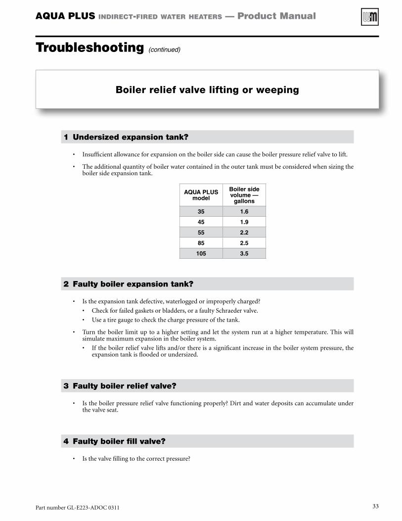
Boiler relief valve lifting or weeping
1 Undersized expansion tank?
• Insufficientallowanceforexpansionontheboilersidecancausetheboilerpressurereliefvalvetolift.
• Theadditionalquantityofboilerwatercontainedintheoutertankmustbeconsideredwhensizingtheboilersideexpansiontank.
AQUA PLUSmodel
Boiler side volume —
gallons
35 1.6
45 1.9
55 2.2
85 2.5
105 3.5
2 Faulty boiler expansion tank?
• Istheexpansiontankdefective,waterloggedorimproperlycharged?
• Checkforfailedgasketsorbladders,orafaultySchraedervalve.
• Useatiregaugetocheckthechargepressureofthetank.
• Turntheboiler limituptoahighersettingand let thesystemrunatahigher temperature.Thiswillsimulatemaximumexpansionintheboilersystem.
• Iftheboilerreliefvalveliftsand/orthereisasignificantincreaseintheboilersystempressure,theexpansiontankisfloodedorundersized.
3 Faulty boiler relief valve?
• Istheboilerpressurereliefvalvefunctioningproperly?Dirtandwaterdepositscanaccumulateunderthevalveseat.
4 Faulty boiler fill valve?
• Isthevalvefillingtothecorrectpressure?
PartnumberGL-E223-ADOC0311 33
AQUA PLUS indirect-fired water heaters — Product Manual
Troubleshooting (continued)
Temperature/pressure relief valve lifting or weeping
1 Undersized or missing domestic water side expansion tank?
• Isthereathermalexpansiontankinstalledonthedomesticsupplypipingandisitproperlysized?• Athermalexpansiontankisrequiredifthedomesticsupplypipingincludesabackflowpreventerorpressurereducing
valve.• Ensurethepotablewaterexpansiontankisproperlysizedaccordingtothewaterheatervolumeandsupplypressure.• Duringlongperiodswhentherearenodrawsfromthetank(i.e.overnight),theT&Preliefvalvemayliftorweepdueto
thermalexpansion,butmayfunctionproperlyduringnormalperiodsoftankdraws.
2 Faulty domestic water side expansion tank?
• Istheexpansiontankdefective,waterloggedorimproperlycharged?• Checkforfailedgasketsorbladders,orafaultySchraedervalve.• Useatiregaugetocheckthechargedpressureofthetank.
3 Faulty T & P relief valve?
• Isthetemperature/pressurereliefvalvefunctioningproperly?Dirtandwaterdepositscanaccumulateunderthevalveseat.
4 High domestic water supply pressure?
• Checkthedomesticsupplypressureenteringthewaterheater.• Ifthepressureisover70psiitisrecommendedtoinstallapressurereducingvalve.Athermalexpansiontankisrequired
ifaPRVisinstalled.• ThiswillpreventanypressurespikesorincreasesinpressureduetothermalexpansionwhichmaycausetheT&Pvalve
toliftorweep.
5 Possible water hammering or pressure spikes?
• Checkthedomesticsystemforpossiblesourcesofwaterhammeringorpressurespikes.• Someappliancessuchasclotheswashersanddishwashersutilizefastactingvalveswhichmaycausewaterhammeringor
pressurespikesthroughthedomesticwatersystem.
• Installwaterhammerarrestorsasrequiredperthemanufacturer’sinstructions,orinstallflexibleconnectorstoisolatethetankfromthedomesticsystem
6 Check boiler operating temperature.
• Iftheboileroperatingtemperatureistoohigh,stackingcanoccurinthewaterheaterraisingthedomesticwatertempera-tureclosetotheboileroperatingtemperature.—Reducetheboileroperatingtemperatureto180°F.Alsofollowpage32suggestionsiftheproblempersists.
PartnumberGL-E223-ADOC031134

AQUA PLUS indirect-fired water heaters — Product Manual
Troubleshooting (continued)
Water on the floor near the tank
1 Check for leaks from sources other than the water heater.
• Checkforpossiblewaterseepagethroughfoundationcracks.Didthewaterappearafteraheavyrain?
2 Is the source of water from the T&P relief valve?
• PlaceabucketunderthedischargepipingoftheT&Preliefvalveandmonitoritforadayortwo.Thisisaprocedurethatcanbedonebythehomeowner.
• IftheT&Preliefvalveisthesource,refertopage34ofthisguide.
3 Loose piping connections?
• Checkallconnections–boilerconnections,domesticconnections,etc.
• Checkalltheboilerconnectionstothewaterheater.• Abuild-upofcorrosionisasuresignofaleak.
• Excessiveforceorwaterhammercandamagetheweldswherethepipingconnectionsenterthewaterheatertank.• Ifwaterisleakingfromaroundoneofthetankconnections,aweldmayhavebeenbroken.Contact
yourWeil-McLainsuppliertodeterminehowtohandletheproblem.
Top of tank or insulation wet
1 Check for leaks from sources other than the water heater
• Checkforpossibleoverheadpipesleakingontothetank.
2 Loose piping connections?
• Checkallconnections–pipingconnectionstothetankandelsewhereifthevicinity.
• Checkaroundvalvestems.
• Abuild-upofcorrosionaroundajointisasuresignofaleak.
PartnumberGL-E223-ADOC0311 35
AQUA PLUS indirect-fired water heaters — Product Manual
Troubleshooting (continued)
Rapid decay of magnesium anode
1 Anodes last less than two years
Thepurposeofthemagnesium anodeistoreducethedamagingeffectsofaggressivewateronthewaterheater.Aggressivewaterwillcausetheanodetoerode.
Theanodemustbeinspectedatleastannuallytodeterminewhetheranewanodeshouldbeinstalled.
Severeorrapiddeteriorationoftheanodeindicatesveryaggressivewater.Ifthisoccurs,havethewatertestedtoverifywhetheritiswithinthelimitsgivenunder“Operatingrestrictions,”page3.
Failuretoinspecttheanoderegularlyandreplaceifnecessarycouldresultindamagetothewaterheater,causingpossibleseverepersonalinjury,deathorsubstantialpropertydamage.
PartnumberGL-E223-ADOC031136
AQUA PLUS indirect-fired water heaters — Product Manual
Water quality problems
1 Water smells like “rotten eggs.”
• Themostcommoncauseofwatertosmelllike“rotteneggs”isanon-toxicsulfatereducingbacteria.
• Thebacteriausuallyenters into thewatersystemthroughabreak in thesupplypipingorduringconstruction/maintenanceofthesupplypiping.
• Thebacteriasurvivesinthewatersystembyconvertingsulfate(SO4)inthewatertohydrogensulfide
(H2S)gas.
• Itisthisgasthatcreatesthe“rottenegg”smell.
• Thepresenceofhydrogensulfidecanalsoaffectthetasteofthewater.
• Alongwiththestenchcausedbythisbacteria,blackdepositsthattypicallyindicatepipeand/orfittingcorrosionmayalsoappearinthewater.
Inextremelyhighconcentrations,hydrogensulfidegascanbetoxic.However,thegasisdetectablepriortoreachingharmfullevels.
• Thebacteriawillthriveinanywatersystemunderthefollowingconditions:
• Highlevelsofsulfurinthewater
• Activatedhydrogeninthewaterfromcathodicreactionswithinthetank
• Waterwithlittleornodissolvedoxygen
• Storingthedomesticwaterbelow130ºF
• Othercausesofsmellywater:
• Chloridesofmagnesiumandcalciumgiveswaterabittertaste
• Chlorideofsodiumwillproduceasaltytastingwater
• Sulfatesabove50ppminthewatergivesthewateramedicinaltaste.
• CarbondioxideinwaterwithalowpHresultsinwaterthatisfizzy.
• Ironandtannicwaterswillproducewaterwithabadtasteandodor.
• Treatment
• Thetreatmentofthissituationrequiresthewatersystemtobeshock-chlorinated.Dependingontheseverityofthebacteriawithinthewatersystem,severaltreatmentsmaybeneeded.
2 Milky water.
• Whenwaterisinitiallydrawnfromthefaucetitappearstobemilkyorcloudy,butitbecomesclearafterthewaterisallowtostandforseveralminutes.
• Thisisusuallyanindicationthatthewatercontainshighlevelsofsolublegases,suchasoxygen,chlo-rine,carbondioxide,hydrogensulfideorothers.
• Asthewatersystempressureincreases,theamountofgasthatwatercanholdinasolutiondecreas-es.
• Whenairandgasesareforcedoutoftheheatedwater,theproblemmaybeevidentinoneorbothofthefollowingconditions:
• Gases,intheformofsmallbubbles,maymakethewaterappearmilkyfromthetap,butclearafterseveralminuteswhenthosebubbleswillseparate.
Troubleshooting (continued)
PartnumberGL-E223-ADOC0311 37
AQUA PLUS indirect-fired water heaters — Product Manual
• Thisissimilartothereactionthatoccursasairbubblesformonthewallsofapanshortlybeforethewaterbeginstoboil.
• Thereleaseofdissolvedgascanalsocreateairpocketsandairlocksinthewatersystempiping.Thiscancausespurtsofairorgaseswhenopeningthehotwaterfaucet.
• Thereisgenerallynocureformilkywatercausedbydissolvegases,althoughitcanbereducedwithaer-atedfaucets.Insomeapplicationstheamountofairandgasesprecipitatingoutofthewaterwillreducedintime.Itshouldbenotedthatthesegasesarenotharmfultotheenduser.
3 Discolored water from the hot water faucet.
• Thewaterfromthehotwaterfaucetappearsdiscolored,eitherrusty,brown,blackoryellow.• Becausethetankisstainlesssteel,whichisresistanttocorrosion,theproblemisnottank-related.• Theproblemisusuallyanon-toxiciron-reducingbacteriathatiscommonlyfoundinsoil,wellwater,
watertreatmentplantsandpipingsystems.• Thebacteriausuallythrivesinsystemsinwhichthesolubleironexceeds0.2ppm.• Thebacteriawillfeedonthesolubleironinthewater,producing“rusty-color”waterasaby-product
ofthefeedingprocess.
• Variablesinwhichthebacteriacanthrive:• Elevatedlevelsofironandmanganeseinthewater• Waterwithlittleornodissolvedoxygen• Waterstoragetemperaturesbelow140ºF
• Itemsthatcanpotentiallyincreasethepresenceofthebacteria:• Watersofteners.• Wellwater.• Longperiodsofnowatermovement.
• Treatment• Treatmentrequiresthewatersystemtobeshock-chlorinated.• Dependingontheseverityofthebacteriawithinthewatersystem,severaltreatmentsmaybeneed-
ed.• CheckthepHandchloridesofthewaterinthewaterheatertankandtheboilersystem.• ThepHmustbebetween6and8.• Chloridesmustbelessthan200ppm.• NotethepHandchloridereadingsonthewarrantysheet.
• ItemsthatcanaffectthepHreading:• Watersofteners.• Watertreatmentplants.• Cl(chlorides)added,especiallyduringthesummer• Fl(fluorides)addedintreatmentinlargecities• Elevatedlevelsofiron,manganese,andsulfur.
• IfthepHishighorlow,thishasamajoreffectonthemetaltanks,pipingandheattransfersurfaces.
Water quality problems (continued)
Troubleshooting (continued)
PartnumberGL-E223-ADOC031138

AQUA PLUS indirect-fired water heaters — Product Manual
Item DescriptionSize/Model
AQUA PLUSWeil-McLain Part Number
1Magnesium anode replacement kit (includes anode, o-ring, insulating washer and brass bushing)
35/45/55 633500014
85 633500015
105 633500016
2 Thermostat repair kit
Aqua PLUS Residential (35/45/55)
633500020
Aqua PLUS Commercial
(85/105)633500021
3 Top plastic cap replacement kit
35/45/55 633500024
85 633500025
105 633500026
4 Bottom plastic cap replacement kit (plastic cap and 4 screws)
35/45/55 633500030
85 633500031
105 633500032
5 Leveling leg replacement kit (4) All 633500036
6 Temperature & pressure relief valve kit
35/45/55 633500038
85/105 633500039
NS Inspection and service kit (includes inspection plate and anode seals) All 633500042
7 Inspection plate replacement kit All 633500044
8 Inspection hatch cover replacement kit All 633500046
9 Fitting grommet ¾”1”
633500064633500037
10 Anode cover All 633500048
NS Jacket replacement kit
35, Pewter 633500049
45, Pewter 633500050
55, Pewter 633500051
85, Pewter 633500052
105, Pewter 633500053
35, Gold 633500054
45, Gold 633500055
55, Gold 633500056
85, Gold 633500057
105, Gold 633500058
NS Mixing valve kit, 1" All 633500012
Replacement parts
Figure 24 Water heater replacement parts
PartnumberGL-E223-ADOC0311 39
AQUA PLUS indirect-fired water heaters — Product Manual
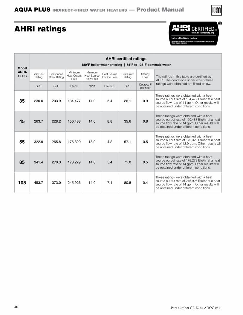
AHRI ratings
Model AQUA PLUS
AHRI certified ratings180°F boiler water entering | 58°F to 135°F domestic water
First Hour Rating
Continuous Draw Rating
Minimum Heat Output
Rate
Minimum Heat Source Flow Rate
Heat Source Friction Loss
First Draw Rating
Standy Loss The ratings in this table are certified by
AHRI. The conditions under which these ratings were obtained are listed below.
GPH GPH Btu/hr GPM Feet w.c. GPH Degrees F per hour
35 230.0 203.9 134,477 14.0 5.4 26.1 0.9
These ratings were obtained with a heat source output rate of 134,477 Btu/hr at a heat source flow rate of 14 gpm. Other results will be obtained under different conditions.
45 263.7 228.2 150,488 14.0 8.8 35.6 0.8
These ratings were obtained with a heat source output rate of 150,488 Btu/hr at a heat source flow rate of 14 gpm. Other results will be obtained under different conditions.
55 322.9 265.8 175,320 13.9 4.2 57.1 0.5
These ratings were obtained with a heat source output rate of 175,320 Btu/hr at a heat source flow rate of 13.9 gpm. Other results will be obtained under different conditions.
85 341.4 270.3 178,279 14.0 5.4 71.0 0.5
These ratings were obtained with a heat source output rate of 178,279 Btu/hr at a heat source flow rate of 14 gpm. Other results will be obtained under different conditions.
105 453.7 373.0 245,926 14.0 7.1 80.8 0.4
These ratings were obtained with a heat source output rate of 245,926 Btu/hr at a heat source flow rate of 14 gpm. Other results will be obtained under different conditions.
®
PartnumberGL-E223-ADOC031140

AQUA PLUS indirect-fired water heaters — Product Manual
Ratings with 200°F boiler supply water
Forwaterheatertoachievetheratedperformancebelow:Boilerwatermustbesuppliedtothewaterheaterat200°F,andtheboilerwaterflowratemustbenolessthangiveninthetablesbelow.(ForUltraGasboiler,UltraOilboilerorGV90+boilerapplications,withsupplywaterat190°F,seetheratingsintheboilermanual.)
Boiler Heating Capacity
MBH
First Hour Rating Capacity (GPH) — Boiler Water Supply at 200°F
Do NoT exceed the boiler-side flow rate listed in “Maximum boiler-side flow rate,” page 23
DHW temps
AQUA PLUS
35
Boiler Water
Min GPM &
Head Loss
AQUA PLUS
45
Boiler Water
Min GPM &
Head Loss
AQUA PLUS
55
Boiler Water
Min GPM &
Head Loss
AQUA PLUS
85
Boiler Water
Min GPM &
Head Loss
AQUA PLUS105
Boiler Water
Min GPM &
Head Loss
50
DH
W 5
0°F
to 1
40°F
93
8 GPM minimum
@
1.6 ft wc
103
8 GPM minimum
@
1.6 ft wc
124
8 GPM minimum
@
1.6 ft wc
138
14 GPM minimum
@
5.4 ft wc
148
14 GPM minimum
@
7.1 ft wc
70 120 130 151 165 175
90 147 157 178 192 202
110 174 184 205 219 229
130 201 211 232 246 256
150 223 237 259 273 283
170 223 243 286 300 310
190 223 243 302 327 337
210 223 243 302 354 363
250 223 243 302 374 417
300 223 243 302 374 483
350 223 243 302 374 483
400 223 243 302 374 483
450 223 243 302 374 483
500 223 243 302 374 483
50
DH
W 5
0°F
to 1
15°F
119
8 GPM minimum
@
1.6 ft wc
129
8 GPM minimum
@
1.6 ft wc
150
8 GPM minimum
@
1.6 ft wc
164
14 GPM minimum
@
5.4 ft wc
174
14 GPM minimum
@
7.1 ft wc
70 157 166 188 201 211
90 194 203 225 239 249
110 231 241 262 276 286
130 268 278 299 313 323
150 306 315 337 351 360
170 337 352 374 388 398
190 337 363 411 425 435
210 337 363 443 462 472
250 337 363 443 537 547
300 337 363 443 551 640
350 337 363 443 551 715
400 337 363 443 551 715
450 337 363 443 551 715
500 337 363 443 551 715
PartnumberGL-E223-ADOC0311 41
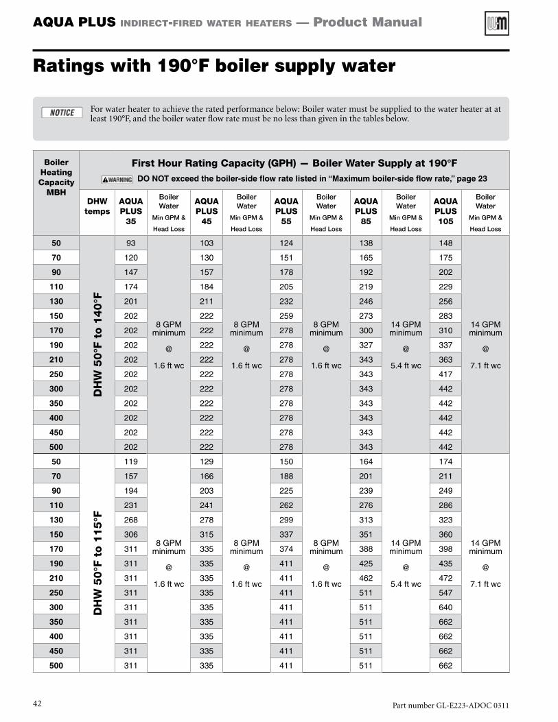
AQUA PLUS indirect-fired water heaters — Product Manual
Ratings with 190°F boiler supply water
Forwaterheatertoachievetheratedperformancebelow:Boilerwatermustbesuppliedtothewaterheateratatleast190°F,andtheboilerwaterflowratemustbenolessthangiveninthetablesbelow.
Boiler Heating Capacity
MBH
First Hour Rating Capacity (GPH) — Boiler Water Supply at 190°F
Do NoT exceed the boiler-side flow rate listed in “Maximum boiler-side flow rate,” page 23
DHW temps
AQUA PLUS
35
Boiler Water
Min GPM &
Head Loss
AQUA PLUS
45
Boiler Water
Min GPM &
Head Loss
AQUA PLUS
55
Boiler Water
Min GPM &
Head Loss
AQUA PLUS
85
Boiler Water
Min GPM &
Head Loss
AQUA PLUS105
Boiler Water
Min GPM &
Head Loss
50
DH
W 5
0°F
to 1
40°F
93
8 GPM minimum
@
1.6 ft wc
103
8 GPM minimum
@
1.6 ft wc
124
8 GPM minimum
@
1.6 ft wc
138
14 GPM minimum
@
5.4 ft wc
148
14 GPM minimum
@
7.1 ft wc
70 120 130 151 165 175
90 147 157 178 192 202
110 174 184 205 219 229
130 201 211 232 246 256
150 202 222 259 273 283
170 202 222 278 300 310
190 202 222 278 327 337
210 202 222 278 343 363
250 202 222 278 343 417
300 202 222 278 343 442
350 202 222 278 343 442
400 202 222 278 343 442
450 202 222 278 343 442
500 202 222 278 343 442
50
DH
W 5
0°F
to 1
15°F
119
8 GPM minimum
@
1.6 ft wc
129
8 GPM minimum
@
1.6 ft wc
150
8 GPM minimum
@
1.6 ft wc
164
14 GPM minimum
@
5.4 ft wc
174
14 GPM minimum
@
7.1 ft wc
70 157 166 188 201 211
90 194 203 225 239 249
110 231 241 262 276 286
130 268 278 299 313 323
150 306 315 337 351 360
170 311 335 374 388 398
190 311 335 411 425 435
210 311 335 411 462 472
250 311 335 411 511 547
300 311 335 411 511 640
350 311 335 411 511 662
400 311 335 411 511 662
450 311 335 411 511 662
500 311 335 411 511 662
PartnumberGL-E223-ADOC031142
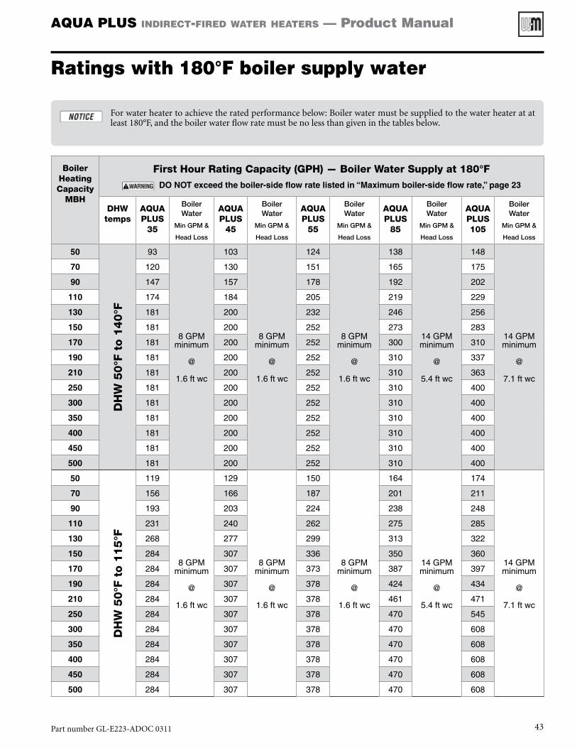
AQUA PLUS indirect-fired water heaters — Product Manual
Ratings with 180°F boiler supply water
Forwaterheatertoachievetheratedperformancebelow:Boilerwatermustbesuppliedtothewaterheateratatleast180°F,andtheboilerwaterflowratemustbenolessthangiveninthetablesbelow.
Boiler Heating Capacity
MBH
First Hour Rating Capacity (GPH) — Boiler Water Supply at 180°F
Do NoT exceed the boiler-side flow rate listed in “Maximum boiler-side flow rate,” page 23
DHW temps
AQUA PLUS
35
Boiler Water
Min GPM &
Head Loss
AQUA PLUS
45
Boiler Water
Min GPM &
Head Loss
AQUA PLUS
55
Boiler Water
Min GPM &
Head Loss
AQUA PLUS
85
Boiler Water
Min GPM &
Head Loss
AQUA PLUS105
Boiler Water
Min GPM &
Head Loss
50
DH
W 5
0°F
to 1
40°F
93
8 GPM minimum
@
1.6 ft wc
103
8 GPM minimum
@
1.6 ft wc
124
8 GPM minimum
@
1.6 ft wc
138
14 GPM minimum
@
5.4 ft wc
148
14 GPM minimum
@
7.1 ft wc
70 120 130 151 165 175
90 147 157 178 192 202
110 174 184 205 219 229
130 181 200 232 246 256
150 181 200 252 273 283
170 181 200 252 300 310
190 181 200 252 310 337
210 181 200 252 310 363
250 181 200 252 310 400
300 181 200 252 310 400
350 181 200 252 310 400
400 181 200 252 310 400
450 181 200 252 310 400
500 181 200 252 310 400
50
DH
W 5
0°F
to 1
15°F
119
8 GPM minimum
@
1.6 ft wc
129
8 GPM minimum
@
1.6 ft wc
150
8 GPM minimum
@
1.6 ft wc
164
14 GPM minimum
@
5.4 ft wc
174
14 GPM minimum
@
7.1 ft wc
70 156 166 187 201 211
90 193 203 224 238 248
110 231 240 262 275 285
130 268 277 299 313 322
150 284 307 336 350 360
170 284 307 373 387 397
190 284 307 378 424 434
210 284 307 378 461 471
250 284 307 378 470 545
300 284 307 378 470 608
350 284 307 378 470 608
400 284 307 378 470 608
450 284 307 378 470 608
500 284 307 378 470 608
PartnumberGL-E223-ADOC0311 43
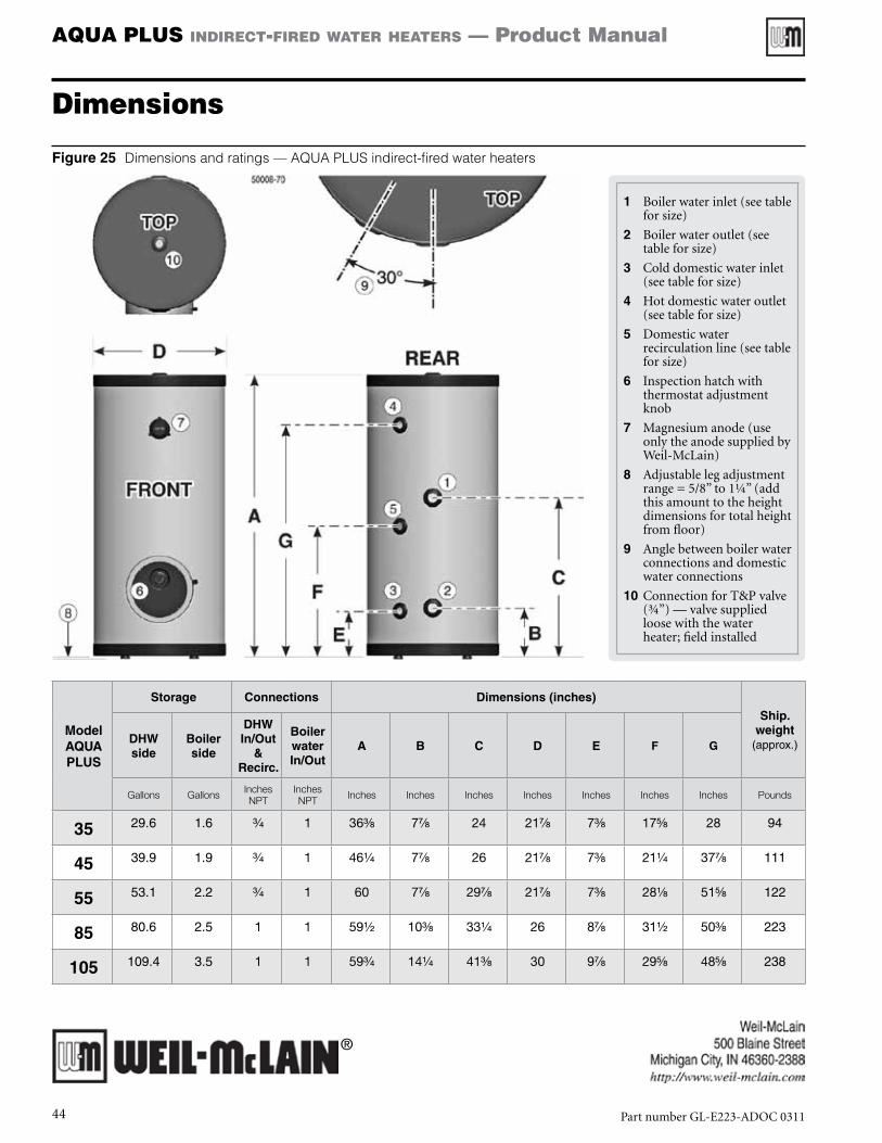
AQUA PLUS indirect-fired water heaters — Product Manual
Dimensions
Figure 25 Dimensions and ratings — AQUA PLUS indirect-fired water heaters
ModelAQUA PLUS
Storage Connections Dimensions (inches)
Ship. weight
(approx.)DHW side
Boiler side
DHW In/out
& Recirc.
Boiler water In/out
A B C D E F G
Gallons Gallons Inches NPT
Inches NPT Inches Inches Inches Inches Inches Inches Inches Pounds
35 29.6 1.6 C\v 1 36C\, 7M\, 24 21M\, 7C\, 17B\, 28 94
45 39.9 1.9 C\v 1 46Z\v 7M\, 26 21M\, 7C\, 21Z\v 37M\, 111
55 53.1 2.2 C\v 1 60 7M\, 29M\, 21M\, 7C\, 28Z\, 51B\, 122
85 80.6 2.5 1 1 59Z\x 10C\, 33Z\v 26 8M\, 31Z\x 50C\, 223
105 109.4 3.5 1 1 59C\v 14Z\v 41C\, 30 9M\, 29B\, 48B\, 238
1 Boilerwaterinlet(seetableforsize)
2 Boilerwateroutlet(seetableforsize)
3 Colddomesticwaterinlet(seetableforsize)
4 Hotdomesticwateroutlet(seetableforsize)
5 Domesticwaterrecirculationline(seetableforsize)
6 Inspectionhatchwiththermostatadjustmentknob
7 Magnesiumanode(useonlytheanodesuppliedbyWeil-McLain)
8 Adjustablelegadjustmentrange=5/8”to1¼”(addthisamounttotheheightdimensionsfortotalheightfromfloor)
9 Anglebetweenboilerwaterconnectionsanddomesticwaterconnections
10 ConnectionforT&Pvalve(¾”)—valvesuppliedloosewiththewaterheater;fieldinstalled
®
PartnumberGL-E223-ADOC031144