TSEWG TP-17 Galvanic (Sacrificial) Anode Material ... (SACRIFICIAL) ANODE MATERIAL SELECTION AND...
58
Electrical TP-17 February 2017 1 ELECTRICAL TECHNICAL PAPER 17 GALVANIC (SACRIFICIAL) ANODE MATERIAL SELECTION AND DESIGN CONSIDERATIONS AND EXAMPLE CALCULATIONS (NON-MANDATORY) Information in this technical paper was excerpted from previous versions of DoD cathodic protection criteria manuals. The information has been updated to reflect current practices and technology. 1.0 ANODES FOR GALVANIC SYSTEMS 1.1 ZINC. Zinc anodes are most commonly used in immersion service either in fresh or salt water. They are, however occasionally used in the protection of buried structures when special circumstances are encountered. Zinc anodes are commonly available in weights from 5 to 250 pounds in the form of plates, bars, and rods. Zinc is also available as ribbon anodes in 5/8" x 7/8", 1/2" x 9/16" and 11/32" x 15/32" sizes, each with a 1/10" diameter galvanized steel wire core. Two zinc anode compositions are commonly available. They are a standard alloy formulated for use in fresh water and soil and an alloy specially formulated for use in seawater. 1.1.2 Composition. Table 1 provides the composition of the standard zinc alloy and the alloy formulated for use in seawater. TABLE 1. COMPOSITION OF ZINC ALLOYS Element Standard Alloy 1 Seawater Alloy 2 Aluminum 0.005 % max 0.10 - 0.50 % Cadmium 0.003 % max 0.025 - 0.15 % Iron 0.00014 % max 0.005 % max Lead 0.003 % max 0.006 % max Copper - 0.005 % max Silicon - 0.125 % max Zinc Remainder Remainder Notes: 1. Specification ASTM B-148-67, Type II 2. Specification ASTM B-148-67, Type I ; or MIL-A-18001H 1.1.3 Anode efficiency. The theoretical anode consumption for zinc is 23.5 pounds per ampere year or 372 ampere-hours per pound. The efficiency of zinc is greater than that of magnesium; commonly in the range of 90% to 95% regardless of current output. For design purposes use 90% efficiency.
Transcript of TSEWG TP-17 Galvanic (Sacrificial) Anode Material ... (SACRIFICIAL) ANODE MATERIAL SELECTION AND...

Electrical TP-17 February 2017
1
ELECTRICAL TECHNICAL PAPER 17 GALVANIC (SACRIFICIAL) ANODE MATERIAL SELECTION AND DESIGN CONSIDERATIONS AND EXAMPLE CALCULATIONS (NON-MANDATORY)
Information in this technical paper was excerpted from previous versions of DoD cathodic protection criteria manuals. The information has been updated to reflect current practices and technology. 1.0 ANODES FOR GALVANIC SYSTEMS 1.1 ZINC. Zinc anodes are most commonly used in immersion service either in fresh or salt water. They are, however occasionally used in the protection of buried structures when special circumstances are encountered. Zinc anodes are commonly available in weights from 5 to 250 pounds in the form of plates, bars, and rods. Zinc is also available as ribbon anodes in 5/8" x 7/8", 1/2" x 9/16" and 11/32" x 15/32" sizes, each with a 1/10" diameter galvanized steel wire core. Two zinc anode compositions are commonly available. They are a standard alloy formulated for use in fresh water and soil and an alloy specially formulated for use in seawater. 1.1.2 Composition. Table 1 provides the composition of the standard zinc alloy and the alloy formulated for use in seawater.
TABLE 1. COMPOSITION OF ZINC ALLOYS
Element Standard Alloy 1 Seawater Alloy 2 Aluminum 0.005 % max 0.10 - 0.50 % Cadmium 0.003 % max 0.025 - 0.15 %
Iron 0.00014 % max 0.005 % max Lead 0.003 % max 0.006 % max
Copper - 0.005 % max Silicon - 0.125 % max Zinc Remainder Remainder
Notes: 1. Specification ASTM B-148-67, Type II 2. Specification ASTM B-148-67, Type I ; or MIL-A-18001H
1.1.3 Anode efficiency. The theoretical anode consumption for zinc is 23.5 pounds per ampere year or 372 ampere-hours per pound. The efficiency of zinc is greater than that of magnesium; commonly in the range of 90% to 95% regardless of current output. For design purposes use 90% efficiency.

Electrical TP-17 February 2017
2
1.1.4 Potentials. The open circuit potential of both commonly used zinc anode materials is -1.10 volts referenced to a copper-copper sulfate reference electrode in most soils or natural waters. The relative potential between zinc and iron is dependent upon temperature. At temperatures above ambient, the potential difference between the two materials is reduced. In some fresh waters, the potential between steel and zinc can reverse at temperatures above 140 degrees F, in which case, the steel will act as anode and corrode to protect the zinc. Zinc should not be used to protect steel in such cases (e.g. do not use zinc anodes to protect a steel hot water storage tank). 1.1.5 Sizes. Both standard alloy and seawater type zinc anodes are available in a wide variety of sizes and shapes. Anodes used in soil usually have a galvanized mild steel rod core. This core is attached to the anode cable during installation of the anode. In both fresh water and seawater applications the anode is often attached directly to the structure to be protected by welding or bolting the steel rod, pipe, or strap core to the structure. When suspended in water, the core is extended by welding a steel extension. For suspended systems, the use of a cable continuity bond is recommended to insure that the resistance between the anode and the structure is minimized. Tables 2 and 3 provide examples of the sizes and shapes of commercially available zinc alloys for cathodic protection. In addition, zinc ribbon anodes 5/8" x 7/8" weighing 1.2 pounds per foot for seawater use are available. Two sizes of zinc ribbon anodes are available in the standard alloy; 1/2" x 9/16" weighing 0.6 pounds per foot and 11/32" x 15/32" weighing 0.25 pounds per foot. All three of these commercially available zinc ribbon anodes have a 1/10" steel core. Many manufacturers can provide material catalogs with detailed anode information and also provide the same information on their company internet websites. TABLE 2. EXAMPLES OF COMMERCIALLY AVAILABLE ZINC ANODES FOR SOIL
AND WATER Nominal Weight * Nominal Dimensions * Bare
(LB) (Kg) Packaged (LB) (Kg)
Bare Anode Ingot (in.) (mm)
Packaged Anode Length X Dia. (in) (mm)
5 (2.3) 24 (10.8) 1.4 x 1.4 x 9 (36 x 36 x 229) 15 x 5 (381 x 127) 12 (5.4) 48 (21.7) 1.4 x 1.4 x 24 (36 x 36 x 610) 30 x 5 (762 x 127) 18 (8.1) 70 (31.7) 1.4 x 1.4 x 36 (36 x 36 x 914.4) 42 x 5 (1067 x 127) 30 (13.6) 95 (43.0) 1.4 x 1.4 x 60 (36 x 36 x 1524) 66 x 5 (1676 x 127) 30 (13.6) 70 (31.7) 2 x 2 x 30 (51 x 51 x 762) 36 x 5 (914 x 127) 45 (20.4) 110 (49.9) 2 x 2 x 45 (51 x 51 x 1143) 51 x 5 (1295 x 127) 60 (27.2) 130 (58.9) 2 x 2 x 60 (51 x 51 x 1524) 66 x 5 (1676 x 127) * Note for Table 2: Refer to manufacturers’ brochures for more specific information. Metric sizes are soft metric conversions from U.S. standard SI units. Actual metric sizes for materials available in foreign countries may differ.

Electrical TP-17 February 2017
3
1.1.6 Current output. The current output of zinc anodes may be determined either by mathematical calculations or by field measurements. When used without backfill, zinc anodes can become covered with non-conductive corrosion products that can reduce their current output. Seawater alloy anodes are specially formulated to reduce this tendency in seawater. When used in soil containing high levels of oxygen, carbonates or phosphates, backfill should be used with zinc anodes in order to reduce the possibility of the buildup of these corrosion products. 1.1.7 Backfill. For soil applications, zinc anodes are commonly prepackaged in cloth bags filled with a special backfill material as shown in Figure 1. Table 4 lists two typical compositions of backfill used with zinc anodes in soils.
TABLE 3. EXAMPLES OF ZINC ANODES FOR USE IN SEAWATER ( see Notes for Table 3)
Nominal Weight (LB) (Kg)
Nominal Dimensions (in.) (mm)
5 (2.3) 1.25 x 3 x 9 (32 x 76 x 229) 12 (5.4) 1.25 x 3 x 12 (32 x 76 x 305) 24 (10.9) 1.25 x 6 x 12 (32 x 152 x 305) 50 (22.7) 2 x 2 x 48 (51 x 51 x 1219) 150 (68.2) 4 x 4 x 36 (102 x 102 x 914) 250 (113.6) 9 x 9 x 12 (229 x 229 x 305) 250 (113.6) 4 x 4 x 60 (102 x 102 x 1524)
Notes for Table 3: 1. Metric sizes are soft metric conversions from U.S. standard SI units.
Actual metric sizes for materials available in foreign countries may differ. 2. The 24-pound and smaller anodes have galvanized steel mounting
straps. The 50-pound size has a 3/8-inch diameter galvanized steel rod for a core. See Figure 2. Larger sizes have a 3/4-inch or 1-inch diameter galvanized steel core rod.
TABLE 4. BACKFILL FOR ZINC ANODES Material Type 1 Type 2
Hydrated Gypsum 75% 50% Bentonite 20% 50%
Sodium sulfate 5% ----

Electrical TP-17 February 2017
4
Figure 1 Zinc anode prepackaged in backfill in a cloth bag.
Figure 2 50 LB zinc anodes with steel cores for use in seawater.

Electrical TP-17 February 2017
5
Figure 3 Special small sized anodes for mooring chain
1.2 Magnesium. Magnesium is the most commonly used sacrificial anode material for the protection of buried structures. Magnesium anodes are also used for the protection of the interiors of water tanks and heaters, heat exchangers and condensers, and in some cases for waterfront structures. However, while they have been used to rapidly polarize structures, magnesium is generally not used for long term cathodic protection of structures in seawater, since their high output current rates will result in rapid consumption of the anodes. Magnesium anodes are available as castings and extrusions weighing from 1 to 200 pounds and in a wide variety of shapes. Figure 4 shows examples of the different sizes and shapes of magnesium anodes. Two anode compositions are commonly used. They are the standard alloy and a "high potential" alloy. The composition of each alloy is given in Paragraph 2-2.

Electrical TP-17 February 2017
6
Figure 4 Bare magnesium anode ingots (left), and extruded magnesium anodes (right).
1.2.1 Composition. Table 5 provides the composition of both the standard alloy and high potential magnesium alloy.
TABLE 5. COMPOSITION OF MAGNESIUM ALLOYS Element Standard High Potential Aluminum 5.3 - 6.7 % 0.1 % max
Manganese 0.15 % min 0.5 - 1.3 % Zinc 2.5 - 3.5 % -
Copper 0.2 % max 0.02 % max Silicon 0.1 % max -
Iron 0.003 % max 0.03 % max Nickel 0.002 % min 0.001 % max
Other Metals 0.3 % max 0.3 % max total 0.05 % max each
Magnesium Remainder Remainder 1.2.2 Anode efficiency. The theoretical efficiency of magnesium is 1000 ampere-hours per pound or 8.8 pounds per ampere-year. The efficiency of magnesium alloys used for cathodic protection seldom exceeds 65% of this theoretical value due to self-consumption. The efficiency of both the standard alloy and high potential alloy magnesium alloys is dependent on the current densities on their surfaces as shown in Figure 5. The efficiency of the standard alloy is higher than the efficiency of the high potential alloy. Thus, the high potential alloy should only be used when its higher driving potential is required. For design calculation purposes, an efficiency of 50% is commonly used.

Electrical TP-17 February 2017
7
Figure 5 Magnesium Anode Efficiency
1.2.3 Potentials. The open circuit potential of the standard alloy is approximately -1.55 volts versus copper/copper sulfate. The open circuit potential of the high potential alloy is approximately -1.75 volts versus copper/copper sulfate. 1.2.4 Sizes. Magnesium anodes are available in a wide variety of sizes and shapes as shown in Tables 6 through 8. Magnesium ribbon anodes are used in situations such as inside casings where the space available is limited, or to protect small diameter utility cables. Many manufacturers can provide material catalogs with detailed anode information and also provide the same information on their company internet websites.

Electrical TP-17 February 2017
8
TABLE 6. EXAMPLES OF COMMERCIALLY AVAILABLE STANDARD ALLOY MAGNESIUM ANODES FOR SOIL AND WATER
Nominal Weight * Nominal Dimensions * Bare
(LB) (Kg) Packaged (LB) (Kg)
Bare Anode Ingot (in.) (mm)
Packaged Anode Length X Dia. (in) (mm)
3 (1.3) 9 (4.1) 3 x 3 x 4.5 (76 x 76 x 114) 6.5 x 6 (165 x 152) 5 (2.3) 14 (6.4) 3 x 3 x 7.5 (76 x 76 x 191) 13.5 x 6 (343 x 152) 9 (4.1) 24 (10.9) 3 x 3 x 13.5 (76 x 76 x 343) 17 x 6 (432 x 152) 17 (7.7) 42 (19.1) 4 x 4 x 17 (102 x 102 x 432) 19 x 6.5 (483 x 165) 32 (14.5) 70 (31.8) 5 x 5 x 21 (127 x 127 x 533) 30 x 8 (762 x 203) 50 (22.7) 110 (49.9) 8 x 15 (203 x 381) 18 x 10 (457 x 254) Note for Table 6: Refer to manufacturers’ brochures for more specific information. Metric sizes are soft metric conversions from U.S. standard SI units. Actual metric sizes for materials available in foreign countries may differ. TABLE 7. EXAMPLES OF COMMERCIALLY AVAILABLE HIGH POTENTIAL ALLOY
MAGNESIUM ANODES FOR SOIL AND WATER Nominal Weight * Nominal Dimensions * Bare
(LB) (Kg) Packaged (LB) (Kg)
Bare Anode Ingot (in.) (mm)
Packaged Anode Length X Dia. (in) (mm)
3 (1.3) 9 (4.1) 3 x 3 x 4.5 (76 x 76 x 114) 6.5 x 6 (165 x 152) 5 (2.3) 14 (6.4) 3 x 3 x 7.5 (76 x 76 x 191) 13.5 x 6 (343 x 152) 9 (4.1) 36 (16.3) 2 x 2 x 27 (51 x 51 x 686) 31 x 5 (787 x 127) 9 (4.1) 24 (10.9) 3 x 3 x 13.5 (76 x 76 x 343) 17 x 6 (432 x 152) 17 (7.7) 61 (27.7) 2 x 2 x 51 (51 x 51 x 1295) 55 x 5 (1397 x 127) 17 (7.7) 42 (19.1) 3 x 3 x 25.5 (76 x 76 x 648) 30 x 6 (762 x 152) 20 (9.1) 70 (31.8) 2 x 2 x 60 (51 x 51 x 1524) 62.5 x 5 (1588 x 127) 32 (14.5) 90 (40.8) 3 x 3 x 45 (76 x 76 x 1143) 61 x 6 (1549 x 152) 32 (14.5) 70 (31.8) 5 x 5 x 21 (127 x 127 x 533) 30 x 8 (762 x 203) 40 (18.1) 105 (47.6) 3 x 3 x 60 (76 x 76 x 1524) 64 x 6 (1626 x 152) 48 (21.8) 96 (43.6) 5 x 5 x 31 (127 x 127 x 787) 34 x 8 (864 x 203) 60 (27.2) 130 (59.0) 4 x 4 x 60 (102 x 102 x 1524) 64 x 6.75 (1626 x 171) Note for Table 7: Refer to manufacturers’ brochures for more specific information. Metric sizes are soft metric conversions from U.S. standard SI units. Actual metric sizes for materials available in foreign countries may differ.

Electrical TP-17 February 2017
9
TABLE 8. EXAMPLES OF COMMERCIALLY AVAILABLE EXTRUDED MAGNESIUM ANODES
Anode Type
Nominal Wt 1 (LB/ft) (Kg/m)
Anode Diameter (in) (mm)
Ribbon 2 0.24 (0.36) 0.375 x 0.75 (9.5 x 19) Rod 0.36 (0.54) 0.75 (19) Rod 0.45 (0.65) 0.84 (21.3) Rod 0.68 (1.01) 1.05 (27) Rod 1.06 (1.58) 1.315 (33) Rod 1.50 (2.24) 1.561 (40) Rod 2.50 (3.73) 2.024 (51)
Notes for Table 8: 1. Refer to manufacturers’ brochures for more specific information. Metric
sizes are soft metric conversions from U.S. standard SI units. Actual metric sizes for materials available in foreign countries may differ.
2. Ribbon anodes have a diamond shaped cross section. 1.2.5 Current output. Current output from magnesium anodes should be determined from formulae or by field measurement. 1.2.6 Backfill. For use in soil, the use of backfill is required in most cases and is highly desirable in most instances. The composition of typical backfill material for use with magnesium anodes is given in Table 9 below:
TABLE 9. BACKFILL FOR MAGNESIUM ANODES
Material Percent Hydrated Gypsum 75%
Bentonite 20% Sodium sulfate 5%
Anodes are available in prepackaged permeable cloth bags filled with prepared backfill. Prepackaged anodes are commonly supplied with an outer impermeable wrapping such as paper and plastic. The impermeable wrapping must be removed from these anodes prior to installation (Figures 6 and 7).

Electrical TP-17 February 2017
10
Figure 6 Packaged magnesium anodes. The outer paper wrapping must be removed.
Figure 7 Packaged magnesium anode with outer paper wrapping removed.

Electrical TP-17 February 2017
11
1.3 Aluminum. Aluminum sacrificial anodes are primarily used for the protection of structures in seawater. However, they have been successfully used in other environments such as fresh water and sewage plant effluent. When the original anodes used are aluminum alloy and their performance has been satisfactory they should generally be replaced with anodes of the same type, unless the original anodes were of the Type I or Type II, mercury-containing anodes. Early formulations of aluminum alloys for use as a sacrificial anode contained mercury. While the amount of mercury contained in the alloy is small the mercury tends to concentrate in the anode stubs that remain after the bulk of the anode has been consumed. Precautions should be taken during removal of the stubs, especially by methods that generate heat, to prevent mercury poisoning. Mercury containing aluminum alloy anode stubs should be disposed of properly. For new and replacement aluminum anode installations, use only the Type III, non-mercury containing anodes 1.3.1 Composition. The compositions of most aluminum alloy anodes are proprietary. Typical compositions of three proprietary alloys are given below:
TABLE 10. COMPOSITION OF ALUMINUM ANODE ALLOYS Element Type I Type II Type III
Zinc 0.35% - 0.50% 3.5% - 5.0% 3.00% Silicon 0.10% max ---- 0.10%
Mercury 0.035% - 0.048% 0.035% - 0.048% ---- Indium ---- ---- 0.02%
Aluminum Remainder Remainder Remainder The Type I alloy is formulated for submersion in full strength seawater, the Type II alloy is formulated for use when the anode may become immersed in bottom sediments, the Type III alloy is formulated for use in bottom sediments, full strength seawater, or in brackish water. 1.3.2 Anode efficiency. The approximate efficiency and consumption rates for the different types of aluminum anodes are listed in Table 11. 1.3.3 Potentials. The approximate potentials for the different types of aluminum anodes are listed in Table 11.

Electrical TP-17 February 2017
12
TABLE 11. ALUMINUM ANODE TECHNICAL INFORMATION Aluminum
Anode Type
Efficiency (amp-hours/
pound) Consumption Rate (pounds/amp-year)
Potential to CuCuSO4 ref.
cell
Potential to AgCl ref.
cell Type I 1280 6.8 -1.10 -1.05 Type II 770 11.4 -1.09 -1.04 Type III 1150 7.6 -1.15 -1.10
1.3.4 Sizes. Aluminum alloy anodes have been developed primarily for the protection of marine structures. They are available in a wide variety of sizes and shapes as shown in Tables 12 through 14 and Figures 8 and 9. As aluminum anode nominal sizes vary amongst the manufacturers, and other sizes may be available, designers should verify anode sizes with the manufacturer before specifying anodes. Depending on the size and type, the anodes are normally supplied with steel cores that can either be an eyebolt, pipe, rod or tabs for either bolt on or welding. The cores can be configured in a variety of ways, again with variation amongst the manufacturers, and the designer should select the appropriate configuration for the structure to be protected.
TABLE 12. EXAMPLES OF COMMERCIALLY AVAILABLE ALUMINUM ANODES FOR PIERS, PILING AND BALLAST TANKS *
NOMINAL WT (LB) (Kg)
NOMINAL DIMENSIONS Length
(in.) (mm) Width
(in.) (mm) Height
(in) (mm) 30 (13.6) 34 (864) 3 (76) 3 (76) 60 (27.2) 12 (305) 7 (178) 7 (178) 60 (27.2) 24 (610) 5 (127) 5 (127) 60 (27.2) 38 (965) 4 (102) 4 (102) 90 (40.8) 18 (457) 7 (178) 7 (178) 90 (40.8) 36 (914) 5 (127) 5 (127) 100 (45.4) 60 (1524) 4 (102) 4 (102) 120 (54.4) 12 (305) 10 (254) 10 (254) 120 (54.4) 24 (610) 7 (178) 7 (178) 120 (54.4) 48 (1219) 5 (127) 5 (127) 175 (79.4) 36 (914) 7 (178) 7 (178) 240 (108.9) 24 (610) 10 (254) 10 (254)
* Note for Table 12: Refer to manufacturers’ brochures for more specific information. Metric sizes are soft metric conversions from U.S. standard SI units. Actual metric sizes for materials available in foreign countries may differ.
Electrical TP-17 February 2017
13
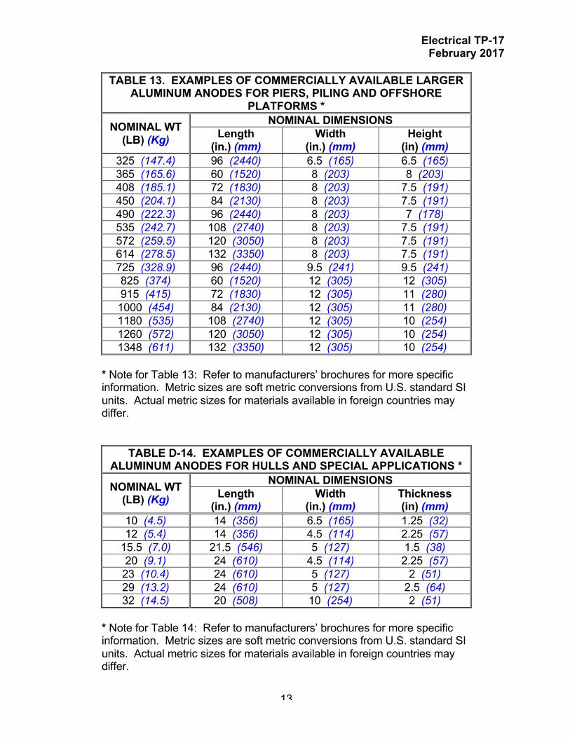
TABLE 13. EXAMPLES OF COMMERCIALLY AVAILABLE LARGER ALUMINUM ANODES FOR PIERS, PILING AND OFFSHORE
PLATFORMS *
NOMINAL WT (LB) (Kg)
NOMINAL DIMENSIONS Length
(in.) (mm) Width
(in.) (mm) Height
(in) (mm) 325 (147.4) 96 (2440) 6.5 (165) 6.5 (165) 365 (165.6) 60 (1520) 8 (203) 8 (203) 408 (185.1) 72 (1830) 8 (203) 7.5 (191) 450 (204.1) 84 (2130) 8 (203) 7.5 (191) 490 (222.3) 96 (2440) 8 (203) 7 (178) 535 (242.7) 108 (2740) 8 (203) 7.5 (191) 572 (259.5) 120 (3050) 8 (203) 7.5 (191) 614 (278.5) 132 (3350) 8 (203) 7.5 (191) 725 (328.9) 96 (2440) 9.5 (241) 9.5 (241) 825 (374) 60 (1520) 12 (305) 12 (305) 915 (415) 72 (1830) 12 (305) 11 (280) 1000 (454) 84 (2130) 12 (305) 11 (280) 1180 (535) 108 (2740) 12 (305) 10 (254) 1260 (572) 120 (3050) 12 (305) 10 (254) 1348 (611) 132 (3350) 12 (305) 10 (254)
* Note for Table 13: Refer to manufacturers’ brochures for more specific information. Metric sizes are soft metric conversions from U.S. standard SI units. Actual metric sizes for materials available in foreign countries may differ.
TABLE D-14. EXAMPLES OF COMMERCIALLY AVAILABLE ALUMINUM ANODES FOR HULLS AND SPECIAL APPLICATIONS *
NOMINAL WT (LB) (Kg)
NOMINAL DIMENSIONS Length
(in.) (mm) Width
(in.) (mm) Thickness (in) (mm)
10 (4.5) 14 (356) 6.5 (165) 1.25 (32) 12 (5.4) 14 (356) 4.5 (114) 2.25 (57)
15.5 (7.0) 21.5 (546) 5 (127) 1.5 (38) 20 (9.1) 24 (610) 4.5 (114) 2.25 (57) 23 (10.4) 24 (610) 5 (127) 2 (51) 29 (13.2) 24 (610) 5 (127) 2.5 (64) 32 (14.5) 20 (508) 10 (254) 2 (51)
* Note for Table 14: Refer to manufacturers’ brochures for more specific information. Metric sizes are soft metric conversions from U.S. standard SI units. Actual metric sizes for materials available in foreign countries may differ.

Electrical TP-17 February 2017
14
Figure 8 Large aluminum anodes for sheet pile bulkhead
Figure 9 Aluminum anodes for hulls and special applications

Electrical TP-17 February 2017
15
1.3.5 Current output. The current output of aluminum anodes can be determined either by the calculations or by field measurements. The current output for some sizes of aluminum anodes is provided by anode manufacturers and is calculated using an assumed structure potential of -850 mv versus copper/copper sulfate and an environmental resistivity of 20 ohm-cm. These values should be considered as estimates only and should be verified by calculation of test. 2.0 ILLUSTRATIVE EXAMPLES OF GALVANIC CP INSTALLATIONS. Figures 10 through 17 illustrate typical cathodic protection system installations. Features of these designs may be applicable to the design of similar systems for similar applications, but the design for each specific application must be made based upon actual specific conditions and requirements. Section 3.0 gives examples of the design calculations for cathodic protection systems.

Electrical TP-17 February 2017
16
Figure 10 Galvanic Anode Type Cathodic Protection for Well Coated Underground
Sewage Lift Station

Electrical TP-17 February 2017
17
Figure 11 Galvanic Anodes Welded Directly to submerged area of the Sheet Pile to Protect
the submerged areas of the Sheet Pile Bulkhead and H-Pile Fenders.
Figure 12 Galvanic Anode (Magnesium) CP System Installed to Protect the Interior
Submerged Areas of an On-Grade Water Storage Tank. Tank Recoated Prior to Installation of the CP System

Electrical TP-17 February 2017
18
Figure 13 Magnesium Anode Installation in a Horizontal Industrial Hot Water Tank

Electrical TP-17 February 2017
19
Figure 14 Pre-Engineered Galvanic CP System for an Underground Storage Tank Conforming
to the Steel Tank Institute STI P3 Standard.
Figure 15 Galvanic Anodes (Aluminum) Welded Directly to Fender H-Piles to
Protect the Fender Piles When Submerged.
Electrical TP-17 February 2017
20
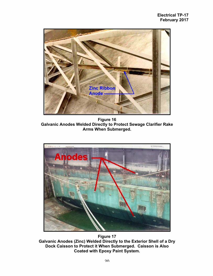
Figure 16 Galvanic Anodes Welded Directly to Protect Sewage Clarifier Rake
Arms When Submerged.
Figure 17 Galvanic Anodes (Zinc) Welded Directly to the Exterior Shell of a Dry
Dock Caisson to Protect it When Submerged. Caisson is Also Coated with Epoxy Paint System.

Electrical TP-17 February 2017
21
3.0 Design Examples. The following simplified examples illustrate the application of the design principles outlined in this Technical Paper as well as Chapters 3 and 4 of UFC 3-570-01. They are intended to illustrate the design methods to be used, but are not standard designs. The examples are also not considered to be mandatory DOD policy and procedures. The policy is described in the main body of this manual. Project engineers may use these examples as guides when technically reviewing project design submissions. In these examples, interference to or from foreign structures is not considered. In practice, the design should be based upon field measurements whenever possible and not on calculated estimates. In some examples, longer calculations than are actually required are presented for illustrative purposes and shorter, more simplified calculations would give equally applicable estimates. Remember that all cathodic protection system designs make many assumptions, such as uniform environmental resistivity, which may or may not prove to be true. When the system is installed, it will require adjustment and possible modification in order for effective protection to be achieved. In congested areas, interference problems are often difficult to correct and optimum levels of protection may not be practically achieved. In such cases, cathodic protection will reduce the incidence and degree of corrosion damage but corrosion may not be entirely eliminated.

Electrical TP-17 February 2017
22
3.1 Natural gas distribution system. Design a galvanic cathodic protection system for a gas distribution system in a housing area as shown in Figure 18.
Figure 18 Layout of Gas Piping in Residential Area
3.1.1 Design data.
A. Average soil resistivity is 4,500 ohm-cm. B. Design for 90 percent coating efficiency, based on experience. C. Design for a 15-year life. D. Design for 2 mA/ft² of bare pipe. E. Use packaged type magnesium anodes. F. Insulating couplings are used on all service taps. The mains are
electrically isolated from all other metal structures in the area. G. All pipe was precoated at the factory and wrapped with asbestos felt. The
coating was tested over the trench for holidays and defects corrected. The coating is considered to be better than 99.5 percent perfect at the time of installation.

Electrical TP-17 February 2017
23
3.1.2 Calculations. 3.1.2.1 Calculate total outside area of piping:
AP = π D L
Pipe Size (in.)
Pipe Length (ft)
Pipe Unit Area (ft²/lin ft)
Area of Pipe (ft²)
3 600 0.916 550 2 1,500 0.622 933
1-1/2 1,800 0.499 899 1 2,400 0.344 826
3/4 3,900 0.278 1,084 Total area of pipe in ft² 4,292
3.1.2.2 Area of bare pipe to be protected based on 90 percent coating efficiency:
A = AP x (1 – CE)
where A = Area of bare pipe to be cathodically protected AP = Outside surface area of the pipe = 4,292 ft² CE = Pipe coating efficiency = 90% or 0.9
A = 4,292 ft² x (1 – 0.9) = 429 ft²
3.1.2.3 Maximum protective current required based on 2 mA/ft² of bare metal.
I = A x CD
where A = Area of bare pipe to be cathodically protected = 1,179 ft² I = Current required for cathodic protection CD = Current density = 2 mA/ft²
I = 429 ft² x 2 mA/ft² = 858 mA or 0.858 A
3.1.2.4 Weight of anode material required based on maximum current requirement
and 15-year life:
Electrical TP-17 February 2017
24
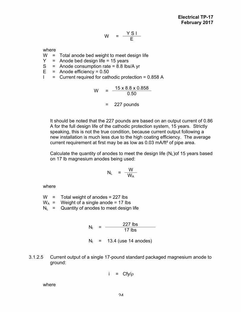
W = Y S I E
where W = Total anode bed weight to meet design life Y = Anode bed design life = 15 years S = Anode consumption rate = 8.8 lbs/A yr E = Anode efficiency = 0.50 I = Current required for cathodic protection = 0.858 A
W = 15 x 8.8 x 0.858 0.50
= 227 pounds
It should be noted that the 227 pounds are based on an output current of 0.86 A for the full design life of the cathodic protection system, 15 years. Strictly speaking, this is not the true condition, because current output following a new installation is much less due to the high coating efficiency. The average current requirement at first may be as low as 0.03 mA/ft² of pipe area. Calculate the quantity of anodes to meet the design life (NL)of 15 years based on 17 lb magnesium anodes being used:
NL = W WA
where
W = Total weight of anodes = 227 lbs WA = Weight of a single anode = 17 lbs NL = Quantity of anodes to meet design life
NI = 227 lbs 17 lbs
NI = 13.4 (use 14 anodes)
3.1.2.5 Current output of a single 17-pound standard packaged magnesium anode to
ground:
i = Cfy/ρ
where

Electrical TP-17 February 2017
25
i = Output (ma) of one anode C = 120,000 for magnesium anode and coated structure f = Size factor = 1.00 y = Structure-to electrolyte potential factor = 1.00 ρ = Soil resistivity = 4,500 ohm-cm
i = (120,000)(1.00)(1.00) 4,500
= 26.7 milliamps
Because the structure is well coated, the anode spacing is relatively great. Therefore, the "multiplying factor for magnesium anode groups" is not used.
3.1.2.6 Calculate quantity of anodes (NI) to satisfy current requirements.
NI = I/i
where
i = Output (ma) of one anode = 26.7 mA I = Current required for cathodic protection = 0.858 A or 858 milliamps NI = Quantity of anodes to meet current requirements
NI = 858 milliamps 26.7 milliamps/anode
NI = 32.1 (use 32 anodes)
3.1.2.7 Anode distribution:
The quantity of anodes required to satisfy both the current requirements and the life requirements would be the larger "N" calculated above. Therefore, use 32 anodes.
A. Area of pipe protected by one anode:
AA = AP N
where

Electrical TP-17 February 2017
26
AP = Outside surface area of the pipe = 4,292 ft² N = Quantity of anodes = 32 AA = Area of pipe protected by one anode
AA = 4292 ft² 32 anodes
= 134 ft²/anode
B. Division of anodes:
Pipe Size (in.)
Area of Pipe (ft²)
Pipe Length (ft)
Quantity of Anodes
Area of Pipe (ft²)
3 550 600 4 150 2 933 1,500 7 214
1-1/2 899 1,800 7 257 1 826 2,400 6 400
3/4 1,084 3,900 8 1,084 Total number of anodes 32
End of Example

Electrical TP-17 February 2017
27
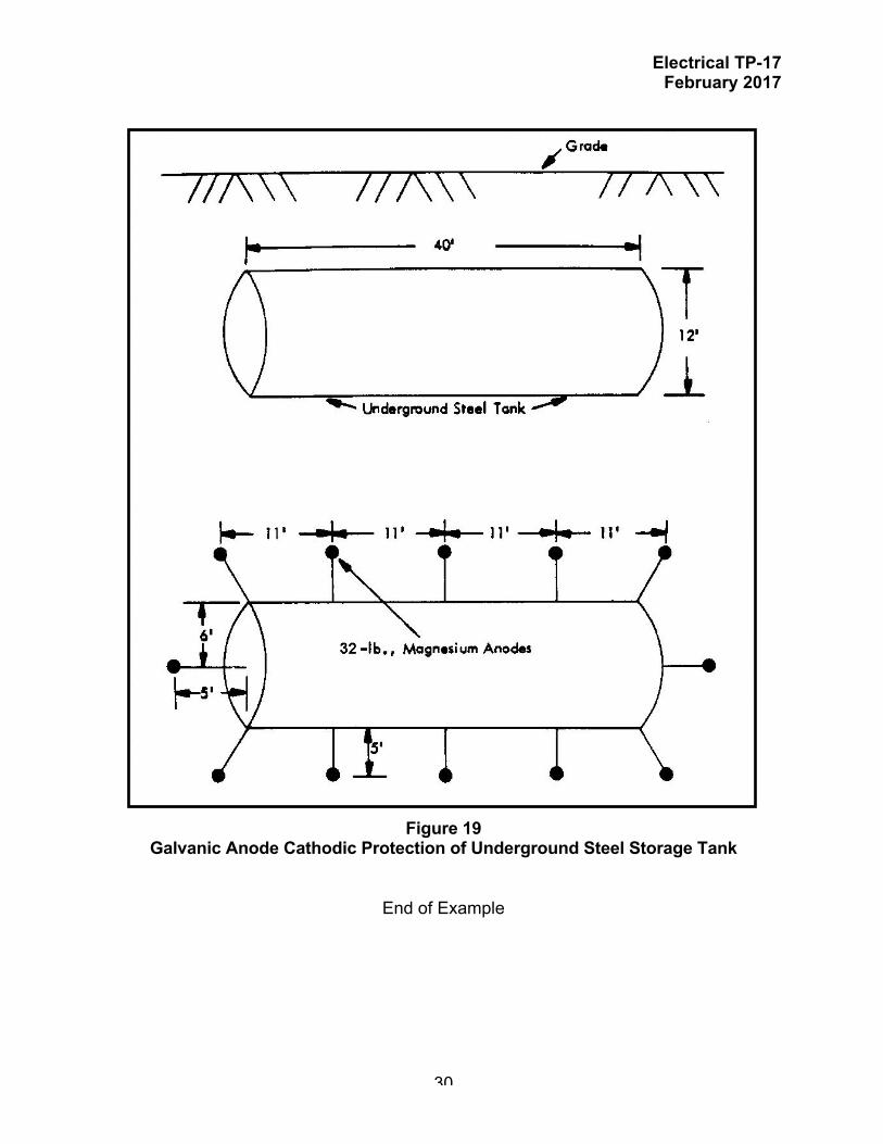
3.2 Underground Storage Tank. Design a galvanic cathodic protection system for an underground storage tank shown in Figure 19. 3.2.1 Design data.
A. Tank Dimensions: 12 ft dia. X 40 ft long B. Coating Efficiency: 80% C. Design Life: 15 Years D. Current Requirement: 0.7 Amperes (700 milliamperes) E. Soil Resistivity: 30,000 ohm-cm F. Other structures: None - tank is effectively electrically isolated from
pipelines and other structures 3.2.2 Calculations. 3.2.2.1 Area to be protected.
Since we have conducted a current requirement test, there is no need to calculate the area to be protected and current required.
3.2.2.2 Determine CP current requirements:
Determined by current requirement test to be 0.7 Amperes 3.2.2.3 Calculate quantity of anodes to meet system life requirements
NL = L S I W u e
where
NL = Quantity of anodes L = Anode life (years) W = Anode weight (lb) S = Anode consumption rate (lb/ampere-year) I = Total system current required (amperes) U = Anode utilization factor - usually 85% e = Anode efficiency
Since the soil resistivity is high, use magnesium anodes. If we arbitrarily select 32 Lb high potential magnesium anodes, then:
NL = Quantity of anodes L = 15 years W = 32 lb S = 8.8 lb/ampere-year I = 0.7 amperes U = 85% e = 50%

Electrical TP-17 February 2017
28
NL = (15 years)(8.8 lb/amp-year)(0.7 amp) (32 lb)(0.85)(0.50)
= 6.6 anodes, say 7 anodes
3.2.2.4 Calculate quantity of anodes to meet the cathodic protection current
requirements
A. Calculate output current for one anode
i = C f y ρ
where
i = Output (ma) of one anode C = 40,000 for zinc anode and coated structure = 120,000 for magnesium anode and coated structure f = Size factor y = Structure-to electrolyte potential factor ρ = Soil resistivity
Since the soil resistivity is high, we have elected to use 32 Lb high potential magnesium anodes, and:
C = 120,000 for magnesium f = 1.06 Y = 1.00 (assume protection level at -0.85 volt) ρ = 30,000 ohm-cm
i = (120,000)(1.06)(1.00) 30,000
= 4.2 milliamps
B. Calculate quantity of anodes to satisfy current requirements
NI = I i
Electrical TP-17 February 2017
29
where
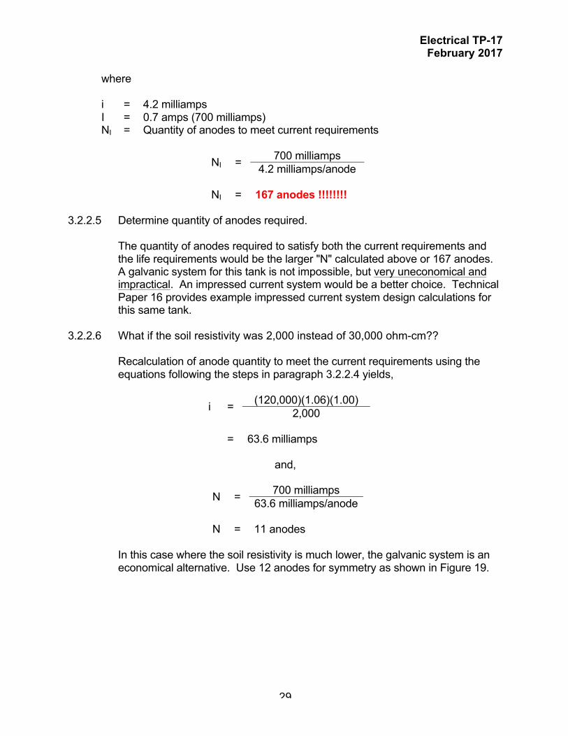
i = 4.2 milliamps I = 0.7 amps (700 milliamps) NI = Quantity of anodes to meet current requirements
NI = 700 milliamps 4.2 milliamps/anode
NI = 167 anodes !!!!!!!!
3.2.2.5 Determine quantity of anodes required.
The quantity of anodes required to satisfy both the current requirements and the life requirements would be the larger "N" calculated above or 167 anodes. A galvanic system for this tank is not impossible, but very uneconomical and impractical. An impressed current system would be a better choice. Technical Paper 16 provides example impressed current system design calculations for this same tank.
3.2.2.6 What if the soil resistivity was 2,000 instead of 30,000 ohm-cm??
Recalculation of anode quantity to meet the current requirements using the equations following the steps in paragraph 3.2.2.4 yields,
i = (120,000)(1.06)(1.00) 2,000
= 63.6 milliamps
and,
N = 700 milliamps 63.6 milliamps/anode
N = 11 anodes
In this case where the soil resistivity is much lower, the galvanic system is an economical alternative. Use 12 anodes for symmetry as shown in Figure 19.
Electrical TP-17 February 2017
30
Figure 19 Galvanic Anode Cathodic Protection of Underground Steel Storage Tank
End of Example

Electrical TP-17 February 2017
31
3.3 Steel H piling in seawater. Galvanic anode cathodic protection is to be provided for an existing 200 feet long by 30 feet wide pier supported by 20 each steel H piles as shown in Figure 20. The piles are coated to the low tide level but are uncoated below the low tide level. A system that can be installed and maintained without divers is desired.
Figure 20
Pier Supported by H-piling 3.3.1 Design data.
a. Seawater Resistivity - 22 ohm-centimeters b. Design for 2 milliamperes per square foot between low tide level and the
bottom, 1 milliampere per square foot in the mud. c. Type III aluminum anodes, suspended from the pier deck will be used. d. The design structure to electrolyte potential for the protected structure will
be –850 mv. e. Design for a 15-year anode life. f. Electrical continuity between piling and the deck reinforcement is good
and no additional bonding will be required. 3.3.2 Calculations. 3.3.2.1 Calculate Total submerged area of pilings Area of 20¸ WF piles is 7 sq. ft. per lineal foot.

Electrical TP-17 February 2017
32
Area in water = 20 piles X 40 ft X 7 sf/ft = 5600 sq. ft. Area in mud = 20 piles X 25 ft X 7 sf/ft = 3500 sq. ft. 3.3.2.2 Calculate Protective current required: In water: 5600 sq. ft. X 4 ma./sq. ft. = 22.4 Amperes In Mud: 3500 sq. ft. X 1 ma./sq. ft. = 3.5 Total current required = 25.9 Amperes 3.3.2.3 Calculate Minimum weight of anodes required for 15 year anode life:
W = YSI Where: W = weight of anodes required Y = design life (15 years) S = Anode consumption (7.6 lbs per ampere year - includes efficiency factor) I = current required (25.9 amperes)
W = 15 x 7.6 x 25.9
= 2953 pounds
As there are 10 bents it is desirable to have at least one anode per bent for adequate current distribution. Thus, anodes weighing at least 300 pounds anodes would be selected provided the current output per anode is sufficient to meet the current requirement.
3.3.2.3 Calculate current output per anode:
Since it desired to have at lease a 300 pound anode, select commercially available 365 LB Type III (mercury free) aluminum anode with dimensions 60 in. long x 8 in. wide x 8 in. high.
*** IMPORTANT *** Do not end calculations at this point. The designer must still calculate the quantity of anodes required to meet the current requirement. Based on the calculation of quantity of anodes to meet the current requirement, the weight of anodes required to meet the design life may need to be recalculated.

Electrical TP-17 February 2017
33
1. Calculate Effective Anode Radius
Initial Radius:
ri = anode cross sectional periphery 2π
= 8" + 8" + 8" + 8" 2π
= 5.09 in.
Derated Radius:
rd = r - rc + rc 2 where rc = radius of anode core
rd = 5.09" - 2" + 2" 2
= 3.55 in.
2. Calculate Anode Resistance
Anode resistance can be calculated as follows:
R = K ρ x [ln (4L/r) - 1] L
where,
K = the constant 0.0627 L = length of the anode (inches) ρ = water resistivity (22 ohm-cm) r = anode radius (inches) R = anode resistance
Initial Anode Resistance (Ri):
Ri = .0627 x 22 x [ln (4 x 60 in/5.09 in) - 1] 60

Electrical TP-17 February 2017
34
= 0.066 Ω
Derated Anode Resistance:
Rd = 0.0627 x 22 x [ln (4 x 60 in/3.55 in) - 1] 60
= 0.074 Ω
3. Anode Current
Calculate anode current using ohms law:
I = Vc - Va R
Initial Anode Current
Ii = [-0.50 - (-1.1)] Volt 0.066 Ω
= 9.1 amps
Anode Operating Current (Current to maintain steel polarized to minimum protective levels of -0.80 Volt for steel).
Ip = [-0.80 - (-1.1)] Volt 0.066 Ω
= 4.6 amps
Derated Anode Current (Steel Polarized to -0.80 Volt). This is the current supplied when the anode is substantially consumed.
Id = [-0.80 - (-1.1)] Volt 0.074 Ω
= 4.1 amps

Electrical TP-17 February 2017
35
Expected Anode Operating Current (Steel Polarized to -0.90 Volt).
Id = [-0.90 - (-1.1)] Volt 0.066 Ω
= 3.0 amps
4. Quantity of Anodes
Calculate quantity of anodes based on derated anode current of 4.1 amp to ensure adequate CP current when the anode is substantially consumed.
Naw = Ireq 4.1 amps/anode
= 25.9 4.1
= 6.3 or 7 anodes
5. Calculate anode life based on expected operation
L = WS Io x 8766 hr/yr
where,
Io = Anode operating current S = Anode current capacity (1176 amp-hr/lb) W = Anode Weight
Calculate anode life base on the calculated operating current of 3.0 amperes.
Lo = 1176 amp -hr/lb x 365 lb 3.0 amp x 8766 hr/yr
= 16.3 years

Electrical TP-17 February 2017
36
3.3.2.4 Final determination of anode size and quantity. Seven 365 pound anodes are required to meet the current requirement and design life of 15 years. However, ten anodes were used, one for each bent, to ensure adequate current distribution.
End of Example 3.4 Steel sheet pile bulkhead in seawater. Galvanic anode cathodic protection is to be provided for an existing sheet pile bulkhead about 660 LF in length by 48 FT high and is constructed of PZ 27 steel sheet piles. The sheet pile was coated between the 8 and 40 Ft depths, and the top 10 FT of the sheet pile was encased in a reinforced concrete pile cap. Electrical continuity across each pile is provided by existing bonding straps welded across each pile joint. The bonding straps are electrically connected together by bonding wires. A system that requires minimal maintenance is desired. Refer to Technical Paper 16 for example calculations for a landside impressed current system. 3.4.1 Design data.
a. Seawater Resistivity - 20 ohm-centimeters b. Design for 10 milliamperes per square foot between low tide level and the
bottom, 1 milliampere per square foot in the mud, and 1 ma/SF for steel in concrete.
c. Type III aluminum anodes, suspended from the pier deck will be used. d. The design structure to electrolyte potential for the protected structure will
be –850 mv. e. Design life: 15+ years f. Coating Efficiency:
Steel sections encased in concrete: 90% (0.9) Steel sections exposed to seawater: 80% (0.8) Steel sections below mudline: 70% (0.7)
3.4.2 Calculations. 3.4.2.1 Calculate total surface area of sheet pile
The bulkhead is constructed of PZ-27 steel sheet piles. PZ-27 sheet pile has a width of 18 inches and a surface area of 2.5 SF/LF on face of the pile. The number of sheet piles (NSP) can be calculated as follows:
NSP = Running Length of sheet pile wall (in inches) 18 inches
= 660 feet x 12 inches/ft 18 inches
= 440 piles

Electrical TP-17 February 2017
37
The surface area for the bulkhead can be calculated using the following equation:
ASP = NSP X Length of sheet pile X 2.5 SF/LF
The bulkhead can be divided into the following zones:
• Water side, encased in concrete, sheet pile bare • Water side, encased in concrete, sheet pile coated • Water side, exposed to seawater, sheet pile coated • Water side, below mudline, sheet pile bare • Water side, below mudline, sheet pile coated
The following table summarizes the surface areas for each zone.
Sheet Pile Zone No. of Piles
Pile Length (LF)
Surface Area (SF)
Waterside
Concrete Bare 440 4 4,400
Coated 440 2 2,200 Seawater Coated 440 18.6 20,460
Mud Bare 440 8 8,800
Coated 440 11.4 12,540 3.4.2.2 Calculate the current required for protection of the sheet pile The current requirement is calculated using the equation:
Ireq = Surface area X (1 - CE) x J
where CE = coating efficiency J = current density
The following table summarizes the current requirements.

Electrical TP-17 February 2017
38
Zones Surface Area (SF) CE J
(ma/SF) Current
Req'd (ma)
Water side
Concrete Bare 4,400 0 1 4,400
Coated 2,200 0.9 1 220 25% of above for concrete cap rebar 1,155
Seawater Coated 20,460 0.8 10 40,920
Mud Bare 8,800 0 2 17,600
Coated 12,540 0.7 2 7,524 Total Water Side Current Required 71,819
or 71.8 amps 3.4.2.3 Calculate Minimum weight of anodes required for 15 year anode life:
W = YSI Where: W = weight of anodes required Y = design life (15 years) S = Anode consumption (7.6 lbs per ampere year - includes efficiency factor) I = current required (71.8 amperes)
W = 15 x 7.6 x 71.8
= 8,185 pounds
Thus, 8,185 pound of anodes would be required to meet the design life of 15 years provided the current output per anode is sufficient to meet the current requirement.
*** IMPORTANT *** Do not end calculations at this point. Do not arbitrarily select an anode size to determine the quantity of anodes. The designer must still calculate the quantity of anodes required to meet the current requirement. Based on the calculation of quantity of anodes to meet the current requirement, the weight of anodes required to meet the design life may need to be reduced or increased.

Electrical TP-17 February 2017
39
3.4.2.3 Calculate current output per anode:
In many cases an anode of over 300 pounds is required to obtain a 15 year life. Select commercially available 365 LB Type III (mercury free) aluminum anode with dimensions 60 in. long x 10 in./9 in. wide x 7.5 in. high.
1. Calculate Effective Anode Radius
Initial Radius:
ri = anode cross sectional periphery 2π
= 10" + 9" + 7.5" + 7.5" 2π
= 5.41 in.
Derated Radius:
rd = r - rc + rc 2 where rc = radius of anode core
rd = 5.41" - 2" + 2" 2
= 3.7 in.
2. Calculate Anode Resistance
Anode resistance can be calculated as follows:
R = K ρ x [ln (4L/r) - 1] L
where,
K = the constant 0.0627 L = length of the anode (inches) ρ = water resistivity (20 ohm-cm) r = anode radius (inches) R = anode resistance
Initial Anode Resistance (Ri):

Electrical TP-17 February 2017
40
Ri = .0627 x 20 X [ln (4 x 60 in/5.41 in) - 1] 60
= 0.06 Ω
Derated Anode Resistance:
Rd = 0.0627 x 22 X [ln (4 x 60 in/3.7 in) - 1] 60
= 0.066 Ω
3. Anode Current
Calculate anode current using ohms law:
I = Vc - Va R
Initial Anode Current
Ii = [-0.50 - (-1.1)] Volt 0.06 Ω
= 10 amps
Anode Operating Current (Current to maintain steel polarized to minimum protective levels of -0.80 Volt for steel).
Ip = [-0.80 - (-1.1)] Volt 0.06 Ω
= 5 amps
Derated Anode Current (Steel Polarized to -0.80 Volt). This is the current supplied when the anode is substantially consumed.
Id = [-0.80 - (-1.1)] Volt 0.066 Ω
= 4.55 amps
Expected Anode Operating Current (Steel Polarized to -0.90 Volt).
Id = [-0.90 - (-1.1)] Volt 0.06 Ω
Electrical TP-17 February 2017
41
= 3.33 amps
4. Quantity of Anodes
Calculate quantity of anodes based on derated anode current of 4.1 amp to ensure adequate CP current when the anode is substantially consumed.
Naw = Ireq 4.55 amps/anode
= 71.8 4.55
= 15.8 or 16 anodes
5. Calculate anode life based on expected operation
L = WS Io x 8766 hr/yr
where,
Io = Anode operating current S = Anode current capacity (1176 amp-hr/lb) W = Anode Weight
Calculate anode life base on the calculated operating current of 3.33 amperes.
Lo = 1176 amp -hr/lb x 365 lb 3.33 amp x 8766 hr/yr
= 15.6 years
3.4.2.4 Final determination of anode size and quantity.
Sixteen 365 pound anodes are required to meet the current requirement and design life of 15 years. Weld the anode cores directly to the sheet pile. For the 660 feet long bulkhead, spacing between anodes should be about 32 feet, center to center. The anodes at either end should be located about 90 feet from the end of the bulkhead. Mount the anode so that the top of the anode is 6 feet below the bottom of the concrete pile cap.
End of Example
Electrical TP-17 February 2017
42
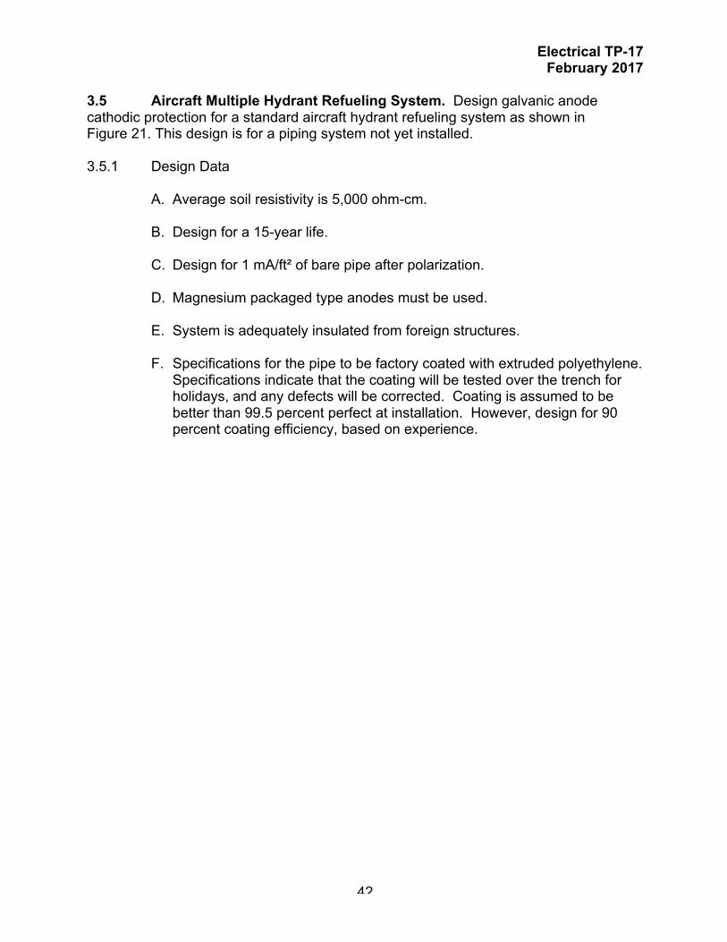
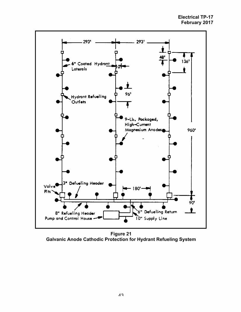
3.5 Aircraft Multiple Hydrant Refueling System. Design galvanic anode cathodic protection for a standard aircraft hydrant refueling system as shown in Figure 21. This design is for a piping system not yet installed. 3.5.1 Design Data
A. Average soil resistivity is 5,000 ohm-cm. B. Design for a 15-year life. C. Design for 1 mA/ft² of bare pipe after polarization. D. Magnesium packaged type anodes must be used. E. System is adequately insulated from foreign structures. F. Specifications for the pipe to be factory coated with extruded polyethylene.
Specifications indicate that the coating will be tested over the trench for holidays, and any defects will be corrected. Coating is assumed to be better than 99.5 percent perfect at installation. However, design for 90 percent coating efficiency, based on experience.
Electrical TP-17 February 2017
43
Figure 21 Galvanic Anode Cathodic Protection for Hydrant Refueling System

Electrical TP-17 February 2017
44
3.5.2 Computations. 3.5.2.1 Total outside surface area of liquid fuel piping serving the hydrant refueling
area:
AP = π D L
Pipe Size (in.)
Pipe Length (ft)
Pipe Unit Area (ft²/ ft)
Area of Pipe (ft²)
3 (defueling header) 2 x 293 = 586 0.916 586 x 0.916 = 537 6 (defueling return) 90 1.734 90 x 1.734 = 156 8 (refueling header) 2 x 293 = 586 2.258 586 x 2.258 = 1,323 10 (supply line) 90 2.814 90 x 2.814 = 253 6 (hydrant laterals) 3 x 960 = 2,880 1.734 2,880 x 1.734 = 4,995
Total area of pipe in ft² 7,264 3.5.2.2 Area of bare pipe based on 90 percent coating efficiency (coating efficiency
deteriorates from 99.5 percent to 90 percent in the15-year life of the cathodic protection system):
A = AP x (1 – CE)
where A = Area of bare pipe to be cathodically protected AP = Outside surface area of the pipe = 7,264 ft² CE = Pipe coating efficiency = 90% or 0.9
A = 7,264 ft² x (1 – 0.9) = 726 ft²
3.5.2.3 Maximum current required based on 1 mA/ft² of bare pipe:
I = A x CD
where A = Area of bare pipe to be cathodically protected = 726 ft² I = Current required for cathodic protection CD = Current density = 2 mA/ft²
I = 726 ft² x 1 mA/ft² = 726 mA or 0.73 A

Electrical TP-17 February 2017
45
3.5.2.4 Weight of anode material required based on maximum current requirement and 15-year life:
W = Y S I E
where W = Total anode bed weight to meet design life Y = Anode bed design life = 15 years S = Anode consumption rate = 8.8 lbs/A yr E = Anode efficiency = 0.50 I = Current required for cathodic protection = 0.73 A
W = 15 x 8.8 x 0.73 0.50
= 193 pounds
It should be noted that the 193 pounds arrived at above is based on an output current of 0.73 A for the full design life of the cathodic protection system, 15 years. Strictly speaking, this is not the case because current output following a new installation is much less due to the high coating efficiency. The average current requirement at first may be as low as 0.015 mA/ft² of pipe area. Calculate the quantity of anodes to meet the design life (NL)of 15 years based on 9 lb magnesium anodes being used:
NL = W WA
where
W = Total weight of anodes = 193 lbs WA = Weight of a single anode = 9 lbs NL = Quantity of anodes to meet design life
NI = 193 lbs 9 lbs
NI = 21.4 (use 22 anodes)
3.5.2.5 Calculate the current output of a single 9-pound high potential packaged magnesium:

Electrical TP-17 February 2017
46
i = C f y ρ
where
i = Output (ma) of one anode C = 120,000 for magnesium anode and well coated structure f = Size factor = 0.71 y = Structure-to electrolyte potential factor = 1.00 ρ = Soil resistivity = 5,000 ohm-cm
i = (120,000)(0.71)(1.00) 5,000
= 17.0 milliamps
Because the structure is well coated, the anode spacing is relatively great. Therefore, the "multiplying factor for magnesium anode groups" (refer to Table 5) is not used.
3.5.2.6 Calculate quantity of anodes (NI) to satisfy current requirements.
NI = I i
where
i = Output (ma) of one anode = 17.0 mA I = Current required for cathodic protection = 0.726 A or 726 milliamps NI = Quantity of anodes to meet current requirements
NI = 726 milliamps 17.0 milliamps/anode
NI = 42.7 (use 43 anodes)
3.5.2.7 Anode distribution:
The quantity of anodes required to satisfy both the current requirements and the life requirements would be the larger "N" calculated above. Therefore, use 43 anodes.

Electrical TP-17 February 2017
47
A. Area of pipe protected by one anode:
AA = AP N
where
AP = Outside surface area of the pipe = 7,264 ft² N = Quantity of anodes = 43 AA = Area of pipe protected by one anode
AA = 7264 ft² 43 anodes
= 169 ft²/anode
B. Division of anodes:
Pipe Size (in.)
Area of Pipe (ft²)
Quantity of anodes
Laterals 4994 4,994/169 = 30 Header 1860 1,860/169 = 11 Supply/Return Lines 410 410/169 = 2
Install anodes as shown in Figure 21.
End of Example

Electrical TP-17 February 2017
48
3.6 On-grade Storage tank with impermeable containment liner. Design galvanic anode cathodic protection for the exterior bottom of a small operational fuel storage tank. An impermeable containment liner will be installed beneath the tank bottom with sand fill between the tank bottom and impermeable liner. This tank is not yet installed.
3.6.1 Design Data
A. Tank bedding will be sand. Assume an initial soil resistivity of sand of 5,000 ohm-cm that will gradually increase to 20,000 ohm-cm as the sand dries out.
B. Tank bottom diameter is 13.25 m. C. Design for a 25-year life. D. Design for 21.5 mA/m² of bare surface area initially and 5.4 mA/m² during
operation after polarization. E. 27 mm (1.05 in.) diameter, high potential extruded magnesium rod anodes
will be used. F. System is adequately insulated from foreign structures. G. Tank bottom surface is bare. (Coating efficiency = 0.0).
3.6.2 Computations. 3.6.2.1 Total surface area of tank bottom plates:
AT = π RT2 x (1 – CE)
where AT = Area of bare steel tank bottom to be cathodically protected RT = Radius of the tank bottom = 13.25 m/2 = 6.625 m CE = Tank bottom coating efficiency = 0.0
NOTE: Galvanic anode systems for on-grade storage tank bottoms are generally not specified because of limited life and limited flexibility for adjustment. Impressed current systems are normally used, however, extenuating circumstances may dictate the use of a galvanic system.

Electrical TP-17 February 2017
49
AT = 3.1416 x (6.625)2 x (1 – 0.0) = 132.7 say 133 m²
3.6.2.2 Calculate current required:
I = A x CD
where A = Area of steel tank bottom to be cathodically protected = 138 m² I = Current required for cathodic protection CD = Current density = 21.5 mA/m² initial and 5.4 mA/m² operating
A. Initial current requirement.
I = 138 m² x 21.5 mA/m² = 2967 mA say 3.0 A
B. Operating current requirement.
I = 138 m² x 5.4 mA/m² = 745 mA
3.6.2.3 Calculate initial anode bed resistance:
The anode rods will be arranged in parallel rows. The industry standard is to space the rows about 24 inches (600 mm) on center for adequate current distribution throughout the tank bottom. Since the sand fill is expected to dry out and result in higher resistivity, use a conservative spacing of 500 mm. At this spacing, 21 rows of anode rods will be required. The total length of anode rods required is 181 m. The average length of each row of anodes is 181/21 = 8.6 m. A. Initial resistance (RI)
Calculate the initial resistance of a single rod with average length of 8.6 m.
RI = 0.0016 ρ x [ ln (8L/d) - 1 ] L

Electrical TP-17 February 2017
50
where
d = diameter of anode = 27 mm or 0.027 m L = length of the anode = 8.6 m RI = anode bed design resistance ρ = soil resistivity (5,000 ohm-cm)
RI = 0.0016 x 5000 x [ ln (8 x 8.6/0.027) - 1 ] 8.6 = 6.36 say 6.4 ohms
Calculate the initial equivalent resistance (RTI) for the 21 rows of anodes. The anodes will be connected in parallel through two separate header cables, one at each end of the rows of anodes. Therefore the equivalent resistance can be approximated by the equation:
1 = 1 + 1 + ···
+ 1
RT R1 R2 R21
where
RTI = Equivalent resistance of the 21 rows of anodes RI = R2 = ··· = R21 = 6.4 ohms
1 = 1 + 1 + ···
+ 1
RTI 6.4 6.4 6.4
1 = 21 RTI 6.4
RTI = 0.3 ohms
3.6.2.4 Calculate initial anode bed output current:
A. Calculate the initial anode bed driving potential (VI). The anode driving potential is the voltage difference between the polarized steel potential (VCI) and the anode open circuit potential (VAI).
VI = VCI - VAI
where

Electrical TP-17 February 2017
51
VI = Initial anode bed driving potential VCI = Initial polarized steel potential = -0.85 volt VAI = Initial anode open circuit potential = -1.75 volts (typical for high-potential
magnesium anodes)
VI = -0.85 – (-1.75) = 0.9 volt
B. Calculate the initial anode bed output current (II).
II = VI RTI
II = 0.9 0.3
II = 3.0 A
This satisfies the initial current requirement calculated in paragraph D-5.6.2.2.
3.6.2.5 Calculate the operating anode bed resistance:
Over time, with the sealant around the chime of the tank preventing the ingress of moisture, the sand fill is expected to dry out to the point where the resistivity will be at 20,000 ohm-cm. A. Operating resistance (RO)
Calculate the operating resistance of a single rod with average length of 8.6 m.
RO = 0.0016 x 20000 x [ ln (8 x 8.6/0.027) - 1 ] 8.6 = 25.6 ohms
Calculate the operating equivalent resistance (RTO):

Electrical TP-17 February 2017
52
1 = 1 + 1 + ···
+ 1
RTO 25.6 25.6 25.6
1 = 21 RTO 25.6
RTI = 1.22 ohms
3.6.2.6 Calculate operating anode bed output current:
As the steel tank bottom polarizes, the current required to maintain the polarization is anticipated to decrease from 3.0 A to 0.726 A (726 mA)
A. Calculate the operating anode bed driving potential (V0). The anode
driving potential is the voltage difference between the polarized steel potential (VCO) and the anode open circuit potential (VAO).
VO = VCO - VAO
where
VO = Initial anode bed driving potential VCO = Initial polarized steel potential = -0.85 volt VAO = Initial anode open circuit potential = -1.75 volts (typical for high-potential
magnesium anodes)
VO = -0.85 – (-1.75) = 0.9 volt
B. Calculate the operating anode bed output current (IO).
IO = VI RTI
IO = 0.9 1.22
IO = 0.74 A
This satisfies the operating current requirement of 726 mA (0.73 A) calculated in paragraph D-5.6.2.2.

Electrical TP-17 February 2017
53
Note that the calculations above are based on assumptions of the condition of the sand fill. These conditions will vary greatly on sand composition, moisture, location, etc. A design for a particular tank must consider the particular conditions of the fill for that tank.
3.6.2.7 Calculate anode bed operating life expectancy:
A. Calculate the weight of anode material
W = WU x LA
where
W = Weight of anode material WU = Unit weight of the 27 mm diameter magnesium anode rod = 1.01 kg/m LA = Total length of magnesium anode rod = 181 m
W = 1.01 x 181 = 183 kg
B. Calculate the estimated theoretical life of the anode bed:
W = Y S I E
Which can be re-arranged into the following form:
Y = W E S I
where Y = Theoretical anode bed life (Years) W = Total anode bed weight = 183 kg S = Anode consumption rate = 4 kg/A-yr E = Anode efficiency = 0.50 I = Current required for cathodic protection = 0.74 A
Y = 183 x 0.50 4 x 0.74
= 30.9 say 31 years
This satisfies and exceeds the design life requirement of 25 years
End of Example

Electrical TP-17 February 2017
54
3.7 Fuel Distribution Pipeline. The project consists of providing a distributed galvanic anode cathodic protection for the trenched segment of a new 3-inch diameter buried fuel pipeline from the base airfield to the upper tank farm and nearby power plant. A separate horizontally drilled segment from the lower tank farm to the airfield will be cathodically protected by an impressed current cathodic protection system (refer to the example in Technical Paper 16. This separate segment will be electrically isolated by a dielectric insulation flange at the tie-in point. 3.7.1 Design Data
A. Average soil resistivity along the pipeline is 3,000 ohm-cm. B. Design for a 25-year life. C. Design for 1 mA/ft² of bare surface area. E. Use a distributed galvanic anode cathodic protection system because of
limited A/C power availability and limited capability at the base for maintaining an impressed current system. Utilize pre-packaged, standard potential magnesium anodes evenly spaced along pipeline. Provide a cathodic protection test station at each anode installation.
F. System will be adequately insulated from foreign structures and the
segment being protected by the impressed current system with dielectric insulating flange kits. Provision for bonding this system to the segment protected by the impressed current system will be included to give versatility to the system and to facilitate potential stray current mitigation if necessary.
G. Pipe length is 12,276 feet. Pipe diameter is 3 inches nominal. Pipe
coating will be extruded polyethylene, and a 95% coating efficiency is assumed.
3.7.2 Computations. 3.7.2.1 Calculate total outside bare surface area of fuel piping for cathodic protection:
AP = π D L x (1-CE)
where AP = Total outside surface area of fuel piping D = Outer pipe diameter = 3.4 inches = 0.283 feet L = Pipeline length = 12, 276 feet CE = Pipeline coating efficiency = 95%

Electrical TP-17 February 2017
55
AP = 3.1416 x 0.283 x 12,276 x (1-0.95) = 1,093 ft²
3.7.2.2 Calculate current required:
I = A x CD
where AP = Surface area of piping to be cathodically protected = 1,091 ft² I = Current required for cathodic protection CD = Current density = 1 mA/ft²
I = 1,091 ft² x 1 mA/ft² = 1,093 mA
3.7.2.3 Weight of anode material required based on maximum current requirement
and 25-year life:
W = Y S I E
where W = Total anode bed weight to meet design life Y = Anode bed design life = 25 years S = Anode consumption rate = 8.8 lbs/A yr E = Anode efficiency = 0.50 I = Current required for cathodic protection = 1,093 mA = 1.093 A
W = 25 x 8.8 x 1.093 0.50
= 241 pounds
It should be noted that the 241 pounds arrived at above is based on an output current of 1.093 A for the full design life of the cathodic protection system, 15 years. Strictly speaking, this is not the case because current output following a new installation is much less due to the high coating efficiency. The average current requirement at first may be as low as 0.015 mA/ft² of pipe area. Use 32 lb anodes for long life. Calculate the quantity of anodes to meet the design life (NL)of 25 years based on 32 lb magnesium anodes being used:

Electrical TP-17 February 2017
56
NL = W WA
where
W = Total weight of anodes = 241 lbs WA = Weight of a single anode = 32 lbs NL = Quantity of anodes to meet design life
NI = 241 lbs 32 lbs
NI = 7.5 say 8 anodes
3.7.2.4 Calculate the current output of a single 32-pound high potential packaged magnesium with dimensions:
A. Calculate the resistance of a single anode.
Ra = [(0.0052ρ)/L] X [ln (8L/d) - 1]
where
Ra = Anode resistance ρ = Soil resistivity = 3,000 ohm-cm L = Anode length = 21 inches = 1.75 feet d = Anode diameter = 5 in. = 0.42 feet
RA = 0.0052 x 3000 [ ln ( 8 x 1.75 ) – 1 ] 1.75 0.42 = 22.3 ohms
20. Calculate the current output a single anode using ohms law:
IA = EC – EA RA

Electrical TP-17 February 2017
57
where
Ra = Anode resistance = 22.3 ohms EA = Anode open circuit potential = -1.55 volts EC = Protected pipe potential = -0.85 volt IA = Anode output current
IA = -0.85 – (-1.55) 22.3
= 0.0314 A or 31.4 mA
3.7.2.5 Calculate quantity of anodes (NI) to satisfy current requirements.
NI = I IA
where
IA = Output (ma) of one anode = 31.4 mA I = Current required for cathodic protection = 1,093 milliamps NI = Quantity of anodes to meet current requirements
NI = 1,093 milliamps 31.4 milliamps/anode
NI = 34.8 say 35 anodes
3.7.2.6 Anode distribution:
The quantity of anodes required to satisfy both the current requirements and the life requirements would be the larger "N" calculated above. Therefore, use 35 anodes spaced about 350 feet apart along the pipeline. Provide a cathodic protection test station at each anode installation.
End of Example

Electrical TP-17 February 2017
58
This Page Intentionally Left Blank