Proceedings of the CERN–Accelerator–School course ...
20
Proceedings of the CERN–Accelerator–School course: Introduction to Accelerator Physics Accelerator Vacuum M. Seidel Paul Scherrer Institut and École Polytechnique Fédéderale Lausanne, Switzerland Abstract This lecture introduces major physics and technology aspects of accelerator vacuum systems. Following an introduction, in the second section generic vacuum quantities such as pressure, gas density, the gas equation, pumping speed, conductance are introduced. Since accelerators typically have lengthy vacuum tubes, one-dimensional calculation is in many cases sufficient to com- pute a pressure profile for an accelerator, and methods for doing so are devel- oped in the next section. In the fourth section accelerator specific aspects of vacuum are considered. This includes lifetime limiting effects for the particle beam, such as bremsstrahlung, elastic and inelastic scattering. Requirements for vacuum properties are derived. In the fifth section types of components and suitable materials for accelerator vacuum systems are described. Such compo- nents are for example flange systems, vacuum chambers for accelerators and the different types of pumps. Keywords Vacuum; accelerator; pressure. 1 Introduction Every particle accelerator needs a vacuum system to transport its particle beams with low losses. With a certain probability beam particles interact with residual gas molecules. The scattering leads to im- mediate particle losses from the beam, or to a deterioration of the beam quality. Both effects are not wanted and the beam losses can even lead to a problematic activation of accelerator components. For different situations, i.e. beam particle species and beam energies, the requirements for the quality of ac- ceptable vacuum conditions can differ significantly. For example in a hadron accelerator with a section that is passed by the beam only once, a pressure of 10 -5 mbar might be sufficient. On the other hand an electron storage ring might need a base pressure of 10 -10 mbar in the absence of beam. Consequently the technology and physics of vacuum systems covers a broad range of effects and concepts, depending on the application. Vacuum systems for electron and proton storage rings are discussed for example in Ref. [1], and a dedicated CERN school on accelerator vacuum is documented under Ref. [2]. Funda- mentals of vacuum physics are discussed in Ref. [3]. Figure1 shows the range of pressure levels from ambient conditions down to the lowest pressures in accelerators. The pressure ranges for typical appli- cations, the volume density of molecules and the mean free path of nitrogen molecules are indicated. The pressure range for beam vacuum is in technical language referred to as Ultra-High-Vacuum (UHV). One often speaks about dynamic vacuum, when the presence of an intense beam affects the residual gas pressure. 2 Pressure and Gas Equation Pressure is basically a force that gas molecules apply to a surface by mechanical momentum transfer, averaged over a huge number of collisions during a macrosopic time interval. Pressure is measured as a force per area. A common unit is Pascal, 1 Pa = 1 N/m 2 . Another common unit is 1 mbar = 100 Pa. The average velocity of molecules depends on the square root of the temperature as shown in Eq. (1). Using the molecule density n v the average velocity can be related to the rate of molecules impinging on the wall of a vessel per area and per time. Available online at https://cas.web.cern.ch/previous-schools 1 arXiv:2105.07675v1 [physics.acc-ph] 17 May 2021
Transcript of Proceedings of the CERN–Accelerator–School course ...

Proceedings of the CERN–Accelerator–School course: Introduction to Accelerator Physics
Accelerator Vacuum
M. SeidelPaul Scherrer Institut and École Polytechnique Fédéderale Lausanne, Switzerland
AbstractThis lecture introduces major physics and technology aspects of acceleratorvacuum systems. Following an introduction, in the second section genericvacuum quantities such as pressure, gas density, the gas equation, pumpingspeed, conductance are introduced. Since accelerators typically have lengthyvacuum tubes, one-dimensional calculation is in many cases sufficient to com-pute a pressure profile for an accelerator, and methods for doing so are devel-oped in the next section. In the fourth section accelerator specific aspects ofvacuum are considered. This includes lifetime limiting effects for the particlebeam, such as bremsstrahlung, elastic and inelastic scattering. Requirementsfor vacuum properties are derived. In the fifth section types of components andsuitable materials for accelerator vacuum systems are described. Such compo-nents are for example flange systems, vacuum chambers for accelerators andthe different types of pumps.
KeywordsVacuum; accelerator; pressure.
1 IntroductionEvery particle accelerator needs a vacuum system to transport its particle beams with low losses. Witha certain probability beam particles interact with residual gas molecules. The scattering leads to im-mediate particle losses from the beam, or to a deterioration of the beam quality. Both effects are notwanted and the beam losses can even lead to a problematic activation of accelerator components. Fordifferent situations, i.e. beam particle species and beam energies, the requirements for the quality of ac-ceptable vacuum conditions can differ significantly. For example in a hadron accelerator with a sectionthat is passed by the beam only once, a pressure of 10−5 mbar might be sufficient. On the other handan electron storage ring might need a base pressure of 10−10 mbar in the absence of beam. Consequentlythe technology and physics of vacuum systems covers a broad range of effects and concepts, dependingon the application. Vacuum systems for electron and proton storage rings are discussed for example inRef. [1], and a dedicated CERN school on accelerator vacuum is documented under Ref. [2]. Funda-mentals of vacuum physics are discussed in Ref. [3]. Figure 1 shows the range of pressure levels fromambient conditions down to the lowest pressures in accelerators. The pressure ranges for typical appli-cations, the volume density of molecules and the mean free path of nitrogen molecules are indicated.The pressure range for beam vacuum is in technical language referred to as Ultra-High-Vacuum (UHV).One often speaks about dynamic vacuum, when the presence of an intense beam affects the residual gaspressure.
2 Pressure and Gas EquationPressure is basically a force that gas molecules apply to a surface by mechanical momentum transfer,averaged over a huge number of collisions during a macrosopic time interval. Pressure is measured asa force per area. A common unit is Pascal, 1 Pa = 1 N/m2. Another common unit is 1 mbar = 100 Pa.The average velocity of molecules depends on the square root of the temperature as shown in Eq. (1).Using the molecule density nv the average velocity can be related to the rate of molecules impinging onthe wall of a vessel per area and per time.
Available online at https://cas.web.cern.ch/previous-schools 1
arX
iv:2
105.
0767
5v1
[ph
ysic
s.ac
c-ph
] 1
7 M
ay 2
021

Fig. 1: Gas pressures ranging from ambient conditions down to cold accelerator vacuum cover 13 orders of mag-nitude.
v =
√8kbπm0
T ,dN
dAdt=
1
4nvv (1)
Here kb = 1.38 × 10⁻²³ J/K is the Boltzmann constant. The gas equation is a fundamental lawrelating pressure, volume, temperature and amount of a gas:
PV = NkbT = nRT. (2)
R = 8.314 N m / mole K is the gas constant. The majority of vacuum systems operate at roomtemperature and we can consider the temperature as being constant. Consequently the product of pressureand volume is a measure of the amount of gas, related to the number of molecules N or the number ofmoles n. In practice a leak rate is often given in terms of mbar l/s, which is the amount of gas that isentering the considered recipient per unit of time. Vacuum systems are equipped with pumps, devicesthat absorb gas molecules. A vacuum pump is characterised by its pumping speed S = Q/P , quantifiedin l/s at its interface. Here Q is the gas load at the interface of the pump. The pumping speed variesfor different gas species. Some chemically inactive gases like the inert gases He, Ar, and for examplemethane (CH4), are pumped less efficiently by several types of pumps like Titanium sublimation pumpsand NEG pumps. Turbo pumps and cryo pumps are not based on chemical binding reactions and aresuited for all gas types. In vacuum systems we can discriminate two types of flow regimes - viscousflow and molecular flow. Viscous flow occurs for higher gas densities. The higher the density of a gasthe shorter is the mean free path between two collisions of a gas molecule with others. The Knudsennumber is the ratio between the mean free path and a typical dimension of the vacuum recipient. If
2
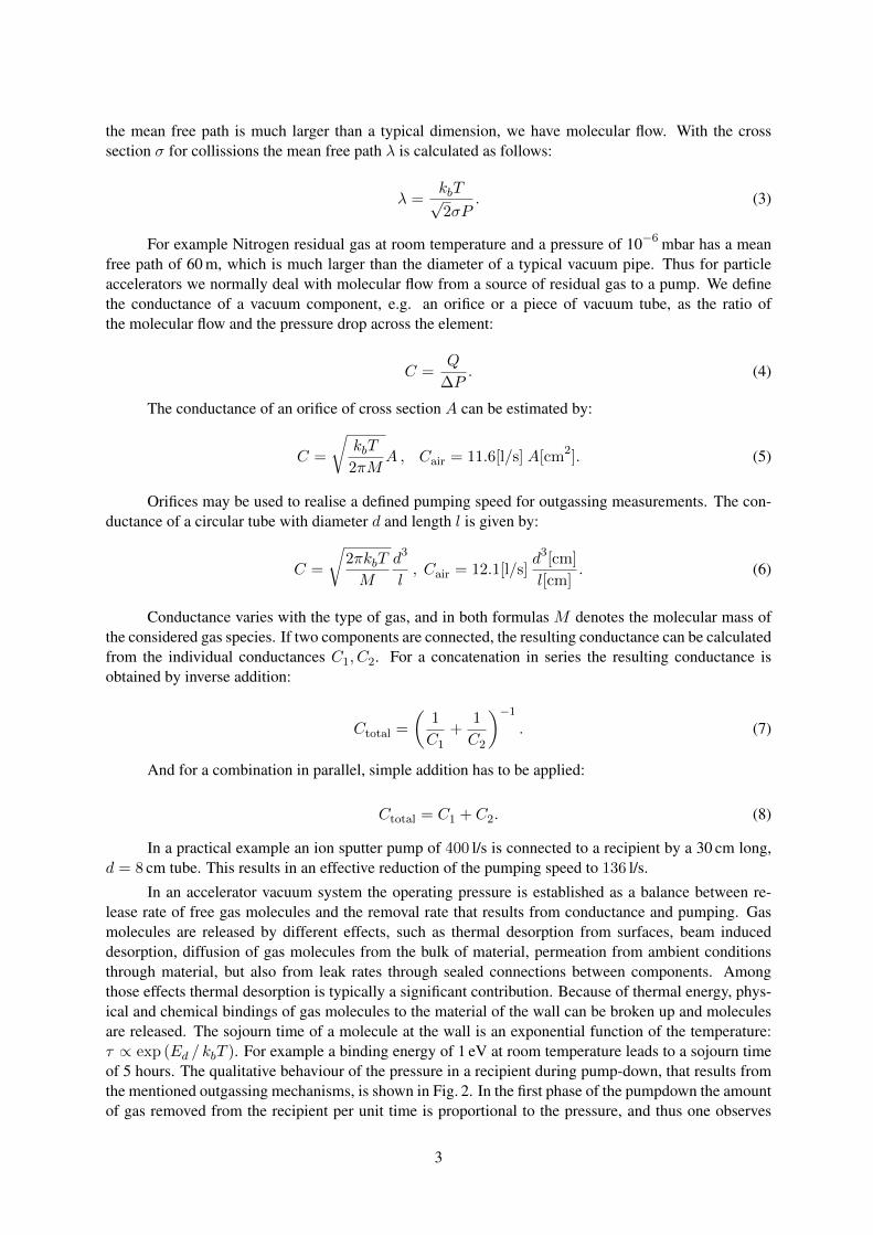
the mean free path is much larger than a typical dimension, we have molecular flow. With the crosssection σ for collissions the mean free path λ is calculated as follows:
λ =kbT√2σP
. (3)
For example Nitrogen residual gas at room temperature and a pressure of 10−6 mbar has a meanfree path of 60 m, which is much larger than the diameter of a typical vacuum pipe. Thus for particleaccelerators we normally deal with molecular flow from a source of residual gas to a pump. We definethe conductance of a vacuum component, e.g. an orifice or a piece of vacuum tube, as the ratio ofthe molecular flow and the pressure drop across the element:
C =Q
∆P. (4)
The conductance of an orifice of cross section A can be estimated by:
C =
√kbT
2πMA , Cair = 11.6[l/s] A[cm2]. (5)
Orifices may be used to realise a defined pumping speed for outgassing measurements. The con-ductance of a circular tube with diameter d and length l is given by:
C =
√2πkbT
M
d3
l, Cair = 12.1[l/s]
d3[cm]
l[cm]. (6)
Conductance varies with the type of gas, and in both formulas M denotes the molecular mass ofthe considered gas species. If two components are connected, the resulting conductance can be calculatedfrom the individual conductances C1, C2. For a concatenation in series the resulting conductance isobtained by inverse addition:
Ctotal =
(1
C1+
1
C2
)−1
. (7)
And for a combination in parallel, simple addition has to be applied:
Ctotal = C1 + C2. (8)
In a practical example an ion sputter pump of 400 l/s is connected to a recipient by a 30 cm long,d = 8 cm tube. This results in an effective reduction of the pumping speed to 136 l/s.
In an accelerator vacuum system the operating pressure is established as a balance between re-lease rate of free gas molecules and the removal rate that results from conductance and pumping. Gasmolecules are released by different effects, such as thermal desorption from surfaces, beam induceddesorption, diffusion of gas molecules from the bulk of material, permeation from ambient conditionsthrough material, but also from leak rates through sealed connections between components. Amongthose effects thermal desorption is typically a significant contribution. Because of thermal energy, phys-ical and chemical bindings of gas molecules to the material of the wall can be broken up and moleculesare released. The sojourn time of a molecule at the wall is an exponential function of the temperature:τ ∝ exp (Ed / kbT ). For example a binding energy of 1 eV at room temperature leads to a sojourn timeof 5 hours. The qualitative behaviour of the pressure in a recipient during pump-down, that results fromthe mentioned outgassing mechanisms, is shown in Fig. 2. In the first phase of the pumpdown the amountof gas removed from the recipient per unit time is proportional to the pressure, and thus one observes
3

Fig. 2: Qualitative pump down behaviour of a recipient. Note the large logarithmic time scale on which 108 scorresponds to three years.
an exponential pressure decay. At some point a balance is reached between pumping speed and releaseof gas molecules from the surface of the walls into the volume of the recipient. In this phase the pres-sure decays inversely with time until the surface is emptied. Afterwards the outgassing is dominatedby molecules that are transported in the bulk material to the surface by thermal diffusion. According tothe nature of diffusion this process scales as 1/
√t. It is possible to reduce this contribution to outgassing
by a heat treatment of the material under vacuum conditions, thereby enhancing diffusion speed [19].Finally an equilibrium is reached when the remaining pressure is dominated by gas that permeates fromthe outside through the wall of the vacuum vessel. Naturally the permeation rate is very small in typicalsituations, and diffusion coefficients in metals are relevant only for light molecules like hydrogen.
So far we have considered thermal outgassing of materials as the main source of gas load ina vacuum recipient. In the presence of an intense particle beam the release of gas molecules fromthe chamber walls can be drastically enhanced, by orders of magnitude, and those effects must be takeninto account and quantified. A prominent effect is photo-desorption due to synchrotron radiation (SR),emitted by an electron or positron beam [4]. When a photon is absorbed on a metallic surface, the photoeffect may lead to the emission of a free electron. Absorption of the electron may then result in the releaseof a gas molecule that was bound on the surface of the vacuum chamber. In a dipole magnet with bendingradius ρ the number of photons emitted per unit length and time is given by:
dNγ
dtds= 1.28 · 1017
I [mA]E [GeV]
ρ [m]. (9)
Here E is the beam energy and I the beam current. The photons exhibit a statistical distribution of theirenergies and the given formula delivers the total number. More details on the properties of synchrotronradiation are given for example in Ref. [5]. The SR induced desorption results in a specific outgassingrate per unit length of:
4
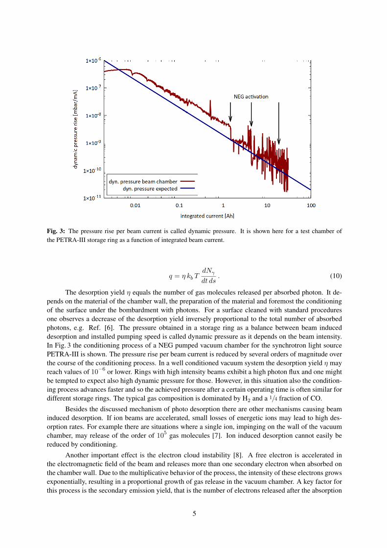
Fig. 3: The pressure rise per beam current is called dynamic pressure. It is shown here for a test chamber ofthe PETRA-III storage ring as a function of integrated beam current.
q = η kb TdNγ
dt ds. (10)
The desorption yield η equals the number of gas molecules released per absorbed photon. It de-pends on the material of the chamber wall, the preparation of the material and foremost the conditioningof the surface under the bombardment with photons. For a surface cleaned with standard proceduresone observes a decrease of the desorption yield inversely proportional to the total number of absorbedphotons, e.g. Ref. [6]. The pressure obtained in a storage ring as a balance between beam induceddesorption and installed pumping speed is called dynamic pressure as it depends on the beam intensity.In Fig. 3 the conditioning process of a NEG pumped vacuum chamber for the synchrotron light sourcePETRA-III is shown. The pressure rise per beam current is reduced by several orders of magnitude overthe course of the conditioning process. In a well conditioned vacuum system the desorption yield η mayreach values of 10−6 or lower. Rings with high intensity beams exhibit a high photon flux and one mightbe tempted to expect also high dynamic pressure for those. However, in this situation also the condition-ing process advances faster and so the achieved pressure after a certain operating time is often similar fordifferent storage rings. The typical gas composition is dominated by H2 and a 1/4 fraction of CO.
Besides the discussed mechanism of photo desorption there are other mechanisms causing beaminduced desorption. If ion beams are accelerated, small losses of energetic ions may lead to high des-orption rates. For example there are situations where a single ion, impinging on the wall of the vacuumchamber, may release of the order of 105 gas molecules [7]. Ion induced desorption cannot easily bereduced by conditioning.
Another important effect is the electron cloud instability [8]. A free electron is accelerated inthe electromagnetic field of the beam and releases more than one secondary electron when absorbed onthe chamber wall. Due to the multiplicative behavior of the process, the intensity of these electrons growsexponentially, resulting in a proportional growth of gas release in the vacuum chamber. A key factor forthis process is the secondary emission yield, that is the number of electrons released after the absorption
5

of one electron. It depends on the type of material and can be reduced by coating of the surface, forexample with TiN or C. Another countermeasure is the application of a small longitudinal magneticfield, by winding a coil around the beampipe, to force the low energy free electrons on spiral paths.
3 Pressure Computation for One-Dimensional SystemsAccelerator vacuum systems are build for beam transport and are typically lengthy, that is the longitudinaldimension is much larger than the transverse dimensions. For a calculation of the pressure profile a one-dimensional calculation is then sufficient. We start the derivation of the corresponding diffusion equationfrom the previously discussed relation between gas flow Q and conductance C in Eq. (4). Note that wehave to introduce at this point a minus sign that ensures positive gas flow towards smaller pressure.In the limit of small differences we obtain a differential equation for the gas flow. Here a specificconductance C = C∆s is introduced, which is a property of the vacuum vessel cross section.
Q ∝ −dP (s)
ds
Q(s) = −C · dP (s)
ds(11)
A second equation is the continuity equation for the gas flow, which expresses that the change inthe amount of transported gas is given by the sum of outgassing from the wall minus the pumped gas ofa considered section with infinitesimal length. Here we use the specific pumping speed S = S/∆s andthe specific outgassing rate q per unit length in mbar l/m s.
dQ(s)
ds= q − S P (s) (12)
These two Eqs. (11) and (12) can now be combined into a second order diffusion equation fora one-dimensional vacuum system with the independent coordinate s.
d
dsC d
dsP (s)− SP (s) + q = 0 (13)
Depending on the nature of the pumps two different types of solutions are obtained for Eq. (13).In the most common situation of systems with lumped pumps the pumping speed S is non-zero onlyfor short sections of the system. In-between these pumps the pressure distribution follows a quadraticfunction with a maximum half-way between a pair of pumps that are installed at a distance l:
P (s) =ql
S+
q
8C
(l2 − 4s2
). (14)
Peak pressure and average pressure for this situation are given by:
Pavg = ql
(1
S+
l
12 C
), Pmax = ql
(1
S+
l
8 C
). (15)
These functions have two terms. Even with infinite pumping speed (left term) the pressure isstill limited by the conduction of the vacuum vessel. The economy of a technical solution is thus to beoptimized w.r.t. density and size of the vacuum pumps, and the transverse dimensions of the vacuumvessel that determine the specific conductance. Besides lumped pumps, also distributed pumps are usedin accelerator vacuum systems. Distributed pumps can be realised by NEG strips or NEG coating, and bydistributed ion sputter pumps that utilize the magnetic field of accelerator magnets. For the case of non-zero pumping speed we obtain an exponential solution of Eq. (13). At some distance from neighboured
6

Fig. 4: Simulated pressure profile in the upper part of the image. The lower part shows the pumping speed alongthe beamline. A d = 10 cm beam pipe is assumed for this demonstration. While the left section contains a 20mlong distributed pump, the right section has 5 lumped pumps installed.
sections the pressure in a long section with distributed pumps approaches a value of P = q/S. Figure 4shows an exemplary calculation of a pressure distribution with lumped pumps in the right part and a longdistributed pump in the left part of the graph.
Pressure profiles can also be calculated in a numerical approach using matrix multiplications [9]:
(P (l)Q(l)
)=
(cosh(αl) − 1
cα sinh(αl)−αc sinh(αl) cosh(αl)
)(P (0)Q(0)
)+q
α
(1−cosh(αl)
αcsinh(αl)
). (16)
Here the variable α =√S/C was introduced. For sections without pumping, S = 0, the elements
containing α in Eq. (16) have to be taken in the limit α → 0, leading to the quadratic profile Eq. (14).So far we have considered the static situation of equilibrium pressure profiles. This is a special case ofthe general time dependent diffusion equation:
V ddtP (s, t) =
d
dsC d
dsP (s, t)− SP (s, t) + q. (17)
The specific volume V denotes the volume of the vessel per unit length. This equation describesalso dynamic evolutions of the pressure profile, for example when He gas is injected for reasons of leaksearch. By comparison with a classical diffusion equation d
dtf(x, t) = ddx D
ddxf(x, t) that is known
from the literature, we identify the diffusion coefficient of our problem as:
7

Fig. 5: A pressure bump of He in this example diffuses in a 2 cm diameter tube at limited speed.
D =< ∆x2 >
< ∆t >=CV. (18)
Using this parameter one can estimate that it takes 3 seconds for He gas to travel a 5 m distance ina 2 cm pipe. Figure 5 shows the time evolution of the pressure distribution for a Delta-function like inletof He gas in such a pipe.
The shown analytic calculations allow one to estimate the pressure in vacuum systems and tocalculate the required number of pumps and their distance. For complex geometries Monte Carlo meth-ods for pressure calculations might be more accurate. The code MolFlow [10] follows individual gasmolecules on their scattered path through a vacuum system, including sticking probabilities and sojourntimes. Pressure and other variables are then calculated as statistical averages. For lepton storage ringsthe code may be augmented by another code, SynRad [11], which allows to simulated the photo desorp-tion process.
4 Requirements for Accelerator Vacuum QualityIn order to assess the required vacuum quality in terms of pressure or density it is necessary to studythe different mechanisms of beam gas interaction. Scattering of beam particles may lead to immediateloss of beam particles, or to a degradation of the beam properties. The number of lost particles ∆Nb
from a beam passing through a section of length ∆l can be estimated in the following way:
∆Nb = −Nb ×area of molecules
total area
= −Nb ×nvV σ
V/∆l
= −Nbnvσ∆l
= −Nbnvσβc∆t .
8

Fig. 6: A beam with Nb particles passes through a volume with residual gas density nv . The gas molecules exhibitan effective cross section σ that describes the interaction probability with the beam for specific processes.
Here σ is the cross section of a generic interaction process, Nb is the number of beam particlesand nv is the volume density of the residual gas. In case the considered scattering mechanism leads tothe loss of the particle, and by converting this relation into a differential equation, the solution is givenby an exponential decay of the beam intensity:
Nb(t) = N0 exp (−σβcnv t) , τ =1
βc σ nv. (19)
The beam lifetime τ is deduced from the exponential solution, and for most situations we cansafely assume β = 1. In the following we consider the effect of different scattering mechanisms forelectrons and protons.
4.1 Coulomb Scattering for ElectronsThis process is described by the well known formula for Rutherford Scattering, which gives the differ-ential cross section for the occurrence of a scattering angle θ:
dσidΩ
=Z2i r
2e
4γ21
sin4(θ/2). (20)
The charge of the residual gas atom is Zi and re = 2.8 fm the classical electron radius. If weintegrate this differential cross section from the angle θ0 above which particles are lost to π and useθ0 1, the total elastic scattering cross section for particle loss is:
σi,el =2π Z2
i r2e
γ21
θ20. (21)
The limiting angle θ0 can be estimated from a typical value for the β-function βy and the minimumapertureAy of the accelerator: θ0 = Ay/βy. Using the parameters for the vertical plane is sufficient sincethe vertical aperture is usually smaller than the horizontal one in electron storage rings. Average valuesof the β functions at the locations of particle scattering and particle loss have to be used. Combiningthe above relations and carrying out the sum over different atom species we obtain the following formulafor the beam lifetime due to elastic scattering:
9

τ−1el =
2πr2ec
γ2βy
2
A2y
∑i
ni∑j
kijZ2j . (22)
Here kij is the number of atoms of type j within the molecule of type i. By inserting numbers forthe fundamental constants and expressing the gas density in terms of pressure at room temperature weobtain the following formula for the beam lifetime in electron rings due to elastic scattering:
τel [h] = 2839E2 [GeV2] A2
y [mm2]
βy2
[m2]
∑i
Pi [pbar]∑j
kijZ2j
−1
. (23)
Note that the quadratic function of Z causes a sensitive dependence of the beam lifetime onthe presence of heavy gas species in the gas composition.
4.2 BremsstrahlungDue to deceleration of a beam particle in the Coulomb field of a residual gas atom and the emission ofa high energy photon, the particle may leave the energy acceptance of the accelerator. The importantparameter in this context is the largest allowed relative energy deviation for the particles to stay confinedwithin the beam: δE = ∆E/E0. The cross section for the inelastic process is
σinel ≈ −4
3
VnNA
1
X0ln δE . (24)
From this the following lifetime τbrems is computed. For a gas mixture one has to sum up contri-butions of gas species with their partial pressures Pi and corresponding radiation lengths X0,i.
1
τbrems= −4
3
c
Pnln(δE)
∑i
PiX0,i
τbrems [h] =−0.695
ln(δE)
(∑i
Pi [pbar]
X0,i [m]
)−1
. (25)
NA is the Avogadro constant and Vn = 22.4 l/mol, Pn the molar volume and the pressure understandard conditions. The radiation length X0 is the length over which a particles energy has dropped bya factor 1/e. X0 scales roughly inversely proportional to the square of the nuclear charge of the resid-ual gas, and also inversely proportional to its density. Radiation length values for common gases undernormal conditions are tabulated for example in Ref. [12]. In Table 1 we list X0 for the important gasesof accelerator vacuum systems. With common energy acceptance and transverse acceptance of stor-age rings, the mechanism of Bremsstrahlung is the more severe mechanism for loss of particles fromthe beam.
4.3 Emittance Growth for HadronsFor a proton or ion beam already the degradation of the beam emittance from elastic gas scattering atsmall angles is harmful. Due to the absence of radiation damping any decrease of the beam density overthe storage time cannot be recovered. For the beam emittance a growth time can be defined:
1
τε=
1
εx
dεxdt. (26)
10

Table 1: Radiation length X0 and inelastic interaction length λi for different gases under atmospheric pressureand 20 C [12].
H2 He CH4 H2O CO N2 Ar CO2 airA 2 4 16 18 28 28 40 44X0 [m] 7530 5670 696 477 321 326 117 196 304λinel [m] 6107 3912 1103 1116 763 753 704 490 747
The scattering causes a diffusive growth of the mean squared angular deviation of the particlesmomentum vector which is linear in time. The emittance growth is related to this angle as follows (θ0 isthe rms scattering angle projected on a transverse plane):
dε
dt=
1
2βy
d(θ20)
dt=
1
2βy
(13.6)2
(cp)2 [MeV2]
c
P0
∑i
PiX0,i
. (27)
Using Eq. (26) the resulting emittance growth time for protons is:
τε [h] ≈ 34.2εy [m rad]E2 [GeV2]T [K]
βy [m]
(∑i
Pi [pbar]
X0,i [m]
)−1
. (28)
The temperature T has been included since proton accelerators often use superconductingmagnets and cold beam pipes. The described mechanism ignores other elastic scatting mechanismsbesides Coulomb scattering.
4.4 Inelastic Scattering for HadronsAnother process is the complete removal of particles from the beam by an inelastic reaction. The beamlifetime for this effect can be computed using the inelastic interaction length λinel which is also tabulatedin Table 1:
1
τinel=βc
P0
∑i
Piλinel,i
. (29)
The inelastic interaction length is related to the corresponding nuclear cross section via λinel =A/ρNA σinel, where A is the molar mass and ρ the density. If we again include the gas temperature andtake out all constants we obtain the following formula for the inelastic beam-gas lifetime:
τinel [h] = 3.2 · 10−3 T [K]
(∑i
Pi [pbar]
λinel,i [m]
)−1
. (30)
5 Vacuum Technology for Accelerators5.1 PumpingAs discussed in the previous sections the average pressures required for accelerators range from10−6 mbar down to 10−11 mbar. For facilities of large size, containing a huge number of components,reliability of the overall system becomes a critical aspect. Pumps without moving mechanical parts arethus advantageous. Figure 7 shows an overview of the most commonly used types of pumps in large
11

Fig. 7: Overview of the most commonly used types of pumps and gauges in large accelerator vacuum systemsincluding their operating range.
accelerator systems. Initial pumpdown of accelerator vacuum systems is often done by turbo-molecularpumps in combination with rotary pumps that are installed on mobile pump carts. During normal opera-tion these are disconnected while the required vacuum conditions are maintained by sputter ion pumps,titanium sublimation pumps (TSP) and non-evaporable getter (NEG) pumps. These types of pumps arealmost exclusively used for routine operation in storage rings and large linear accelerators.
Turbo-molecular pumps are fully mechanical pumps, based on a mechanism to transfer physi-cal momentum to residual gas molecules in a preferred direction. The momentum transfer is achievedthrough fast moving blades with rotation frequencies of 30 . . . 60 · 103 RPM (rounds per minute). Atthese rotation frequencies the blades reach a speed of 300 . . . 600 m/s, which is to be compared withthe speed of the residual gas molecules that should ideally not escape the blades. At room temperatureheavier molecules like CO have a speed of 470 m/s, while hydrogen moves at 1800 m/s. Consequentlythe compression ratio (gas density ratio) achieved with a turbo-molecular pump may vary by severalorders of magnitude for these gas species. Turbo-molecular pumps are always combined with mechani-cal roughing pumps that provide an intermittent vacuum level between UHV conditions and the normalatmospheric pressure.
Sputter ion pumps are capable of pumping all gases and they can be operated at relatively highpressure. These pumps use penning cells with an applied high voltage of 3. . . 7 kV and a superimposedmagnetic field. Permanent magnet blocks are used to generate the magnetic field. Residual gas moleculesare ionized and accelerated in the electric field. The current drawn from the high voltage power supplyis thus proportional to the residual gas pressure. This synergy is often used to measure the pressure inaccelerators in a cost effective way. Hydrogen is pumped by diffusion into the bulk of the cathodes. Allother reactive gases are chemisorbed by the cathode material. A commonly used material is titanium,which is sputtered onto the walls and anodes by the ions upon incident on the cathodes. Noble gasesare physically buried by the sputtered cathode atoms. The pumping speed for noble gases is small, butit can be increased to values of 25 − 30 % of that for N2 replacing the cathode plate by heavy materialsuch as tantalum. Such noble diodes are often used in systems with enhanced risk of helium leaks as in
12

Fig. 8: Penning cells are elements in ion sputter pumps to ionize residual gas molecules. In a combined electricand magnetic field electrons are accelerated on spiral paths, thereby enhancing their efficiency to ionize neutral gasmolecules. Ions are then also accelerated and implanted in the cathod material or burried under sputtered metal onthe anodes.
accelerator sections using superconducting magnets or resonators cooled with liquid helium.
A cost effective solution are so-called integrated sputter ion pumps inserted linearly into a channelparallel to the beam channel [13], [14]. These pumps utilize the magnetic field of the bending magnetsof the accelerator. This solution has been adopted at the electron ring of HERA, PETRA, PEP andTRISTAN reaching typical pump speeds of 25 l/s/m. On the downside this couples the functions ofthe accelerator magnets and the vacuum system. Magnets must be powered to maintain pumping. In-between ramp cycles of storage rings these pumps are not active. Furthermore the magnetic field intensityis decreased when the particles are injected at lower energies, resulting in a reduced pumping speed. Thisbecomes crucial for accelerators where the injection energy and thus the corresponding magnetic field aremuch lower than the nominal beam energy, such that the discharge in the sputter ion pumps extinguishes.Thus additional pumps are required to ensure good vacuum conditions.
Titanium sublimation pumps are sorption pumps. In a metallic vessel titanium is evaporated bytemporary electrical heating and deposited on the walls, forming a getter surface. These pumps exhibita high pumping speed for active gases but have limited pumping capacity since the thin titanium filmsaturates quickly. The pumping surface is renewed by deposition of fresh titanium from a heated fil-ament by sublimation. A pump with 1000 l/s pumping speed is saturated after one hour at a pressureof 10−7 mbar. Titanium sublimation pumps cannot pump noble gases and are therefore used in com-bination with a low pumping speed ion sputter pump. Often a chicane is incorporated in the pumpingport, to avoid that titanium atoms enter the beam chamber or contaminate surfaces, e.g. mirrors, ceramicinsulators or instrumentation.
Non-evaporable getter (NEG) pumps are sorption pumps as well. The NEG material is madeof special alloys which forms stable chemical compounds with the majority of active gas molecules.The sorption of hydrogen is reversible by heating of the material. Also NEG pumps have a limitedpumping capacity. The NEG material is activated by heating for times below one hour. Activation
13

Fig. 9: Concept view of a vacuum chamber with integrated NEG pump for an electron beam storage ring. The alu-minum profile is extruded with integrated cooling channels. The synchrotron radiation is absorbed on the left sideof the chamber, while the right side contains the NEG strip (blue) in a side channel, which is shielded from directview to the beam to suppress capture of dust particles (courtesy DESY).
temperatures depend on the NEG material and range from 180C to 400C. During heating the gasmolecules are not evaporated from the NEG material, but the molecules diffuse into the bulk material.Hydrogen is an exception, which is released again into the gas phase, thus requiring other pumps duringthe process of activation and reactivation. The heating produces fresh surface sites for further adsorptionof active gases. The NEG material is a compound of different metals, for example Zircon, Vanadium,Iron, and is typically sintered in the form of a powder onto flexible strips. Such strips can be integratedin a side channel of the vacuum chamber design. The initial specific pumping speed provided by suchschemes may exceed 1000 l s−1 m−1. This technique has been developed for LEP [15] and is now appliedin many accelerators. At LEP about 24 km of the beam pipe have been equipped with 30 mm wideand 0.2 mm thick constantan ribbons coated with 0.1 mm thin NEG material on both sides. A newerapplication for the synchrotron light source PETRA-III is shown in Fig. 9. The strips are installed ontoa rigid stainless steel carriage via insulating ceramics inside a separate pump channel. For electric heatingthe pumps are connected to current feedthroughs. NEG pumps are also available commercially as lumpedpumps, cartridge units that can be connected to recipients by standard flange connections.
Another approach to the NEG pumping concept is the deposition of thin film coatings of TiZrV,sputtered onto a vacuum chamber. The activation temperature of these coatings is relatively low, a factthat is important to limit the thermal stress on the vacuum system during activation [16], [17]. If the de-sign of the vacuum chamber allows that, the coating may cover the complete inner surface of the beamvacuum system and thus the outgassing of the vacuum vessel itself is drastically reduced. It should beemphasised that even with low activation temperature the need for baking the entire vacuum system toca. 200 C implies severe restrictions for the design of vacuum chambers, support structures and mag-nets. For accelerators in which the vacuum conditions are dominated by beam induced desorption, it ispossible to reduce outgassing with NEG coated surfaces in the vicinity of the particle beam. In partic-ular for light sources NEG coated surfaces are advantageous to reach good vacuum conditions withoutlong conditioning times [18]. Modern light sources use complex multi-bend achromat lattice cells toachieve extremely small horizontal emittances. As a result the apertures of vacuum chambers are small,and the achievable pressure is conductance limited. Lumped pumping concepts are less efficient in thissituation since a large number of pumps had to be installed per unit length. Today it is common forsuch light sources to use NEG coating for efficient pumping of the narrow beam chambers. Also hadronaccelerators benefit from NEG coated chambers through the reduction of the secondary emission yieldof electrons [20].
14

Fig. 10: Concept view of a cryo pump with a large aperture flange connection on the top side (courtesy LotharSchulz, PSI).
Cryo pumps use the effect of cryosorption to bind gas molecules on cold surfaces inside the pumpvessel. With sufficiently low temperature these pumps can remove all gas species and they provide highpumping speed and capacitance. On the downside cryo pumps must be regenerated by regular warm-upcycles, for which the accelerator operation must be interrupted. During the regeneration cycle all pumpedgases are released again, and are typically removed from the vacuum system by turbo molecular pumps.A concept sketch of a cryo pump is shown in Fig. 10.
For performance reasons many accelerators make use of superconducting magnets or supercon-ducting accelerating structures. With the beam pipe being integrated into the cryostat this leads to a coldbore vacuum system, which takes on the characteristics of a huge cryopump. Design and operation ofsuch cold bore vacuum systems have many specific implications [21].
5.2 InstrumentationAccelerator based research infrastructures are expensive installations, they use a lot of grid energy andtheir operation should be efficient and reliable. Also for vacuum systems it is therefore important thatthe integrity of the system is continuously monitored and problems like leaks or regions of unusual highpressure resulting from beam impact can be identified quickly to allow fast and targeted intervention.Using gate valves the beam vacuum system of accelerators is divided into several sections. In this wayit is possible to exchange components without venting the entire facility. Fast shutters, capable to stopshock waves in milliseconds, are commonly used to avoid contamination of sensitive sections caused bya sudden break of the vacuum system.
Each of the segments of a larger vacuum system should have at least one gauge to monitor the in-tegrated residual gas pressure. Total pressure gauges are included in Fig. 7 with their operating range.For practical operation it is usually not necessary to obtain precise absolute measurements, but to be ableto diagnose relative changes over time and to compare sections with each other. Cold cathode gaugesor Bayard-Alpert gauges are frequently used at low pressures. Current monitoring of sputter ion pumpsis a cost effective method, particularly for large facilities to monitor the residual gas pressure down tolevels of 10−9 mbar.
Using quadrupole mass spectrometers the residual gas composition in a vacuum system can beanalysed. The relative occurrence of molecule masses is determined, which allows to diagnose problemsin an accelerator vacuum system. For example it can be determined whether a leak or a contaminationis the reason for unusually high pressure. Such residual gas analysers (RGA) are typically not part ofa standard installation, but these are temporarily connected to the recipient. Often the sensitive elec-
15

Table 2: Properties of materials that are utilized for accelerator vacuum components.
density thermal electrical yieldconductivity conductivity strength
[g/cm3] [W/K/m] [106/Ω/m] [N/mm2]stainless steel 316LN 8.00 16 1.35 205aluminum pure 2.70 235 37 35AlMgSi0.5 2.70 200 30 70-150copper pure 8.95 394 58 40-80Cu Sn2 8.90 140 25 150
tronics is not compatible with the radiation environment of the stray magnetic fields of an accelerator inoperation.
5.3 Materials and Technology Choices for Accelerator Vacuum SystemsFor large facilities production cost can be optimized by a careful design and by utilization of industrialmanufacturing processes. For example extrusion processes serve as a cost effective method to producelarge lengths of beam pipe profiles. Over time a wide variety of best practices have been developed foraccelerator vacuum systems and more details may be found for example in Ref. [2].
Materials for the manufacturing of beam chambers and other beam vacuum components have tobe selected carefully according to the specific requirements of each accelerator. A significant numberof aspects must be addressed in parallel. The air pressure under normal conditions on a surface area of10×10 cm2 results in a force equivalent to the weight of 100 kg. Consequently mechanical robustness isalready one important criterion for a vacuum chamber, while the costly aperture of accelerator magnetsmight favour a thin wall solution. Vacuum chambers should be bake-able and thus stability must beguaranteed also at elevated temperatures. The magnetic guide field for the beam should not be disturbedby magnetic properties of the beam chamber. If synchrotron radiation is deposited on the chamber walla high thermal conductivity is desirable. And the transport of beam image currents in the chamber wallsrequires good surface conductivity and smooth electrical connections across components. For machinessusceptible to electron cloud instabilities the secondary electron emission yield of the material shouldbe low. Last but not least the compatibility with UHV vacuum conditions and low outgassing ratesare important. The requirement of UHV class pressure in combination with resistance to radiation andcorrosive atmospheres demands all metal solutions for beam vacuum system.
Stainless steel, copper or aluminum are the most common vacuum chamber materials. Electricaland thermal conductivity are by factors better for copper and aluminum surfaces compared to steel. Onthe other hand the mechanical strength of steel is outstanding. Copper and aluminum alloys exhibitbetter mechanical strength than the pure metals, at the expense of somewhat lower conductivity. A fewproperties for common materials are listed in Table 2. Joining techniques for materials of vacuum systemsinclude inert gas shielded arc welding, electron-beam welding, laser beam welding as well as brazing ina furnace. Laser and electron beam welding can deposit large amounts of heating power to a small volumein a short time. These technologies can be used advantageously for welding of sensitive components thatallow only local heating while another part of the component must be kept at moderate temperature.
Aluminum or copper are favoured for electron facilities due to their high thermal conductivity.The synchrotron radiation can be absorbed directly by the vacuum chamber if the power line-density isnot exceeding values of ≈ 100 W/m. With appropriate water cooling of the chamber a power load ofseveral 10 kW/m can be accepted. For intense synchrotron radiation fans with a shallow height the tem-perature profile should be simulated. The often quite elaborate beam pipe cross sections in combination
16

Fig. 11: In a ConflatTM metal sealed flange connection the copper seal is clamped between two stainless steelflanges that contain a knife edge.
with pumping and cooling ducts can be economically produced by continuous extrusion as shown in theexample of Fig. 9. More complex chambers are produced from solid blocks, which is associated withhigher manufacturing cost. Neighboured chambers may be connected by aluminum flanges in combina-tion with HelicoflexTM gaskets. Alternatively aluminum/stainless steel transitions, for example made byexplosion bonding, allow the usage of standard stainless steel ConflatTM flanges. Overall the sealing ofaluminum systems is not as reliable as the standard stainless steel system with copper gaskets.
In some cases copper or copper alloy chambers are used to benefit from the even higher conduc-tivity compared to Al. Examples include the accelerator facilities HERA-e, KEK-B and PEP. Brazingtechniques are typically applied to join copper components and to connect stainless steel flanges. Mas-sive water cooled copper blocks are often used as collimators or absorbers for synchrotron radiation atlocations of high power density.
For proton accelerators austenitic stainless steel has become the most widely used material. Beampipes are often fabricated from seamless tubes with discrete pumps attached every few meters. Forsealing usually welded stainless steel flanges and copper ConflatTM gaskets are used. Only metal sealedflange connections allow to achieve leak rates compatible with UHV conditions and radiation resistanceat the same time. A concept sketch of the Conflat system is shown in Fig. 11.
For accelerators with superconducting magnets the vacuum chamber is often also operated atlow temperature, since there is no room for thermal insulation in the tight space between the magnetcoils. Examples include the proton ring of HERA/DESY, RHIC at Brookhaven and LHC at CERN.The cool down over a large temperature range from room temperature to an operating temperature of, forexample, 4.5 K presents another challenge for the beam vacuum system. A system of bellows and spacefor expansion must be foreseen to handle the mechanical contraction. Usually the beam pipes are madefrom a type of stainless steel with the inner surface coated by copper to enhance the thermal conductivity.
For electrical feedthroughs into vacuum ceramics are used as insulators. In some cases ceramicsare used for entire vacuum chambers. This is necessary if the chamber is to be placed in rapidly changingmagnetic fields, and in a metallic chamber strong eddy currents would be induced. Applications includefor example kicker magnets and rapid cycling synchrotrons [22]. Beam chambers inside particle physicsdetectors should influence particles generated at the interaction point as less as possible. For this purposevery thin wall tubes are used, made from low Z material, such as aluminum, beryllium or carbon fibermaterials. For exit windows of beams similar solutions are common.
The beam chamber carries an image current that acts back on the beam and may deteriorate beamquality properties like emittance or energy spread. To minimize such effects the chamber should carrythe image current with low resistance, avoiding geometric discontinuities. Variations of the vacuumchamber cross section should be applied gradually using tapered sections. Bellows and openings forpumping ports must be electrically shielded. In bellows often a set of flexible, sliding spring contacts ofcopper-beryllium alloys is installed around their circumference. Perforated electric screens with circularholes of some millimeters diameter or longitudinal slits are used for pump ports. Of course such electrical
17

Fig. 12: Attenuation length for X-rays of commonly used materials for vacuum vessels and shielding as a functionof photon energy.
shielding measures result in a reduction of the effective pumping speed. Also for gate valves in the openstate, gaps have to be covered by spring contacts that move with the gate mechanism. Inappropriateshielding of transverse openings will not only affect the beam quality, but may also result in the excitationof trapped RF modes, leading to a strong heating effect for vacuum components.
Accelerator components installed in the vicinity of the beam pipe should be radiation resistantand must withstand corrosive atmospheres produced by the primary radiation. This includes cablesand electronics, which must either be properly chosen or shielded. For high energy electron/positronstorage rings and synchrotron radiation facilities the generated X-rays may cause problems, and oftenthe beam chamber is wrapped into a lead shield to absorb as much radiation as possible. Figure 12 showsthe attenuation of X-rays in various materials as function of the photon energy. Using beam energy andbending radius the critical photon energy may be estimated with the expression:
Ec[keV] ≈ 2.218E3[GeV3]
ρ[m]. (31)
6 SummaryThe vacuum system presents a challenging technical aspect of each particle accelerator. To achieverequired beam lifetimes and beam quality, and to minimize unwanted losses of high energy particlesassociated with radio-activation and damage to components, vacuum systems must be carefully designedto provide the adequate low gas densities.
Steps for designing an accelerator vacuum system can be roughly categorized into three groups.The first step involves an evaluation of the gas sources in an accelerator. This includes outgassingrates for surfaces and beam induced outgassing dynamics, such as synchrotron radiation, electron cloud,heavy ion bombardment to name a few. Certain accelerator designs require quick handling of acti-vated components thus involving relatively leaky inflating seals. In such cases leak rates must be
18

considered. In practice a clean and baked stainless steel surface might exhibit an outgassing rate ofq0 = 10−11 mbar l s−1 cm−2. In the presence of synchrotron radiation and after a reasonable time ofconditioning the outgassing is still dominated by releasing at least η = 10−6 gas molecules per photonincident on the chamber wall.
The second step covers the definition of the target residual gas pressure and composition (moreprecisely the gas density). Physics effects of beam gas interaction and the resulting performance degra-dation must be considered for this purpose. To give a couple of examples the acceptable dynamic gaspressure in an electron storage ring is in the order of 10−8 mbar with a typical composition of 3/4 H2 and1/4 CO. A proton cyclotron as a single pass accelerator is more forgiving and a pressure of 10−6 mbar issufficient.
The third step involves then to lay out the vacuum system in terms of geometry, installed pumpingspeed and perhaps more complex technical measures like surface coating to achieve the required vacuumquality under operating conditions. Types of pumps may include turbo pumps, ion sputter pumps, NEGcoating or cryo pumps for large recipients. A typical electron storage ring may be equipped with S =100 l/s ion sputter pumps at a distance of 5 m. Today software can be used to compute the pressureprofile using Monte Carlo methods or numerical solutions of the diffusing Eq. (13). In addition to suchconceptual considerations the design of vacuum systems requires a lot of engineering. Keywords include:UHV compatible materials and materials preparation, mechanical stability, thermo-mechanical problemsunder heat load, pumps, gauges, flange systems and valves.
References[1] C. Benvenuti, R. Calder, O. Gröbner, Vacuum for particle accelerators and storage rings, Vacuum
37 (1987) 699.[2] CERN Accel. School on Vacuum for Particle Accelerators, ed. H. Schmickler, CERN ACC-2020-
0009 (2017), https://cds.cern.ch/record/2721872/files/CERN-ACC-2020-0009.pdf.[3] P.A. Redhead, J.P. Hobson, E.V. Kornelsen, The physical basis of ultra-high vacuum, AVS Classics
in Vacuum Science and Technology, Springer (1993).[4] G.E. Fischer, R.A. Mack, Vacuum Design Problems of High Current Electron Storage Rings, J. Vac.
Sci. Technol. 2 (1965) 123.[5] M. Seidel, K. Zapfe, Particle Accelerators, in Book Vacuumelectronic Devices, Eichmeier and
Thumm (ed.)[6] J.C. Billy et al., The pressure and gas composition evolution during the operation of the LEP accel-
erator at 100 GeV, Vacuum 60 (2001) 183.[7] A. Sen, Vacuum simulations for heavy ion beams in the AGOR cyclotron, Proc. 19th Int. Conf. on
Cyclotrons and Their Applications, Lanzhou, 2010, pp. 221–223,http://accelconf.web.cern.ch/Cyclotrons2010/papers/mopcp083.pdf.
[8] F. Zimmermann, The electron cloud instability: Summary of measurements and understanding,Proc. PAC01. (2001) pp. 666 - 670.
[9] V. Ziemann, Vacuum Tracking, SLAC/Pub/5962 (1992),https://www.slac.stanford.edu/pubs/slacpubs/5750/slac-pub-5962.pdf.
[10] R. Kersevan et al, MolFlow code available at: https://molflow.web.cern.ch/.[11] R. Kersevan et al, Synrad code and tutorial:
https://molflow.web.cern.ch/content/synrad-documentation.[12] R.M. Barnett et al., Review of Particle Physics, Physical Review D54 (1996) 1.[13] U. Cummings et al., Vacuum System for Stanford Storage Ring, SPEAR, J. Vac. Sci. Technol. 8
(1971) 348.[14] H. Hartwig and J.S. Kouptsidis, A new approach for computing diode sputter-ion pump character-
19

istics, J. Vac. Sci. Technol. 11 (1974) 1154.[15] C. Benvenuti, A new pumping approach for the large electron positron collider (LEP), Nucl. Instr.
and Meth. 205 (1983) 391.[16] C. Benvenuti et al., Nonevaporable getter films for ultrahigh vacuum applications, J. Vac. Sci. Tech-
nol. A16(1) (1998) 148.[17] C Benvenuti et al., A novel route to extreme vacua: the non-evaporable getter thin film coatings,
Vacuum 53 (1999) 219.[18] P. Chiggiato, R. Kersevan, Synchrotron radiation-induced desorption from a NEG-coated vacuum
chamber, Vacuum 60 (2001) 67, https://cds.cern.ch/record/435199/files/est-1999-004.pdf.[19] R. Calder and G. Lewin, Reduction of stainless-steel outgassing in ultra-high vacuum, Brit. J. Appl.
Phys. 18 (1967) 1459.[20] W. Fischer et al, Electron cloud observations and cures in the Rela-
tivistic Heavy Ion Collider, Phys. Rev. ST Accel. Beams 11, 041002https://journals.aps.org/prab/pdf/10.1103/PhysRevSTAB.11.041002.
[21] O. Gröbner, Overview of the LHC vacuum system, Vacuum 60 (2001) 25.[22] H. Dong et al, The vacuum system of the China spallation neutron source, Vacuum 154, (2018) pp.
75-81.
20