Accelerator Physics Aspects LHCb [email protected] CERN SL/AP

David Alesini
(INFN-LNF, Frascati, Rome, Italy)
Linear Accelerator Technology

ACKNOWLEDGEMENTS
Several pictures, schemes, images and plots have been taken from papers and presentations reported at
the end of the presentation.
I would like to acknowledge all the following authors:
Hans Weise, Sergey Belomestnykh, Dinh Nguyen, John Lewellen, Leanne Duffy, Gianluigi Ciovati,
Jean Delayen, S. Di Mitri, R. Carter, G. Bisoffi, B. Aune, J. Sekutowicz, H. Safa, D. Proch, H.
Padamsee, R. Parodi, E. Jensen, Paolo Michelato, Terry Garvey, Yujong Kim, S. Saitiniyazi, M.
Mayierjiang, M. Titberidze, T. Andrews, C. Eckman, Roger M. Jones, T. Inagaki, T. Shintake, F.
Löhl, J. Alex, H. Blumer, M. Bopp, H. Braun, A. Citterio, U. Ellenberger, H. Fitze, H. Joehri, T. Kleeb,
L. Paly, J.Y. Raguin, L. Schulz, R. Zennaro, C. Zumbach. Detlef Reschke, David Dowell, K. Smolenski,
I. Bazarov, B. Dunham, H. Li, Y. Li, X. Liu, D. Ouzounov, C. Sinclair

WHAT DOES IT MEANS LINAC TECHNOLOGY?Electron
sources
NC Accelerating
structures
RF sources
Waveguide
components
Fabrication
techniques
Cryostat for SC
structures
Power
distribution
SC Accelerating
structures
Tuning, RF
measurements
But also: quadrupoles,
magnets, vacuum,
beam diagnostics
devices,…
…For FEL and ERL…

ACCELERATING CAVITIES
To accelerate charged particles, the RF wave must
have an electric field along the direction of
propagation of the particle. There are basically two
possibilities:
1-Using standing wave (SW) TM010-like modes in a
resonant cavity (or multiple resonant cavities) in
which the beam is synchronous with the resonating
field;
2-Using a travelling wave (TW) disk loaded structure
operating on the TM01-like mode in which the RF
wave is co-propagating with the beam with a phase
velocity equal to the beam velocity (c for e-).
Ez
z
Direction of propagation
Ez
z
⇒The structures are powered by RF generators (typically klystrons).
⇒The cavities (and the related LINAC technology) can be of
different material:
• copper for normal conducting (NC, typically TW) cavities;
• Niobium for superconducting cavities (SC, typically SW);
⇒We can choose between NC or the SC technology depending on
the required performances in term of:
• accelerating gradient (MV/m);
• RF pulse length (how many bunches we can contemporary
accelerate);
• Duty cycle: pulsed operation (i.e. 10-100 Hz) or continuous wave
(CW) operation;
• Average beam current.
P RF in
P RF inP RF out
P RF TW

SW CAVITIES

SW CAVITIES PARAMETERS: Vacc, Pdiss, W
)( ∫=cavity
v
zj
zacc dzezEVRFω
[ ] )(Re),(E tjzz
RFezEtz ω=We suppose that the cavities are
powered at a constant frequency fRF.
The maximum energy gain of a particle
crossing the cavity at a velocity v (∼c for
electrons) is obtained integrating the
time-varying accelerating field sampled
by the charge along the trajectory:
To compare different technologies is necessary to define
some parameter that characterize each accelerating
structure.
Real cavities have losses.
Surface currents (related to the surface magnetic field
) “sees” a surface resistance and dissipate
energy, so that a certain amount of RF power must be
provided from the outside to keep the accelerating field
at the desired level. The total dissipated power is:
ACCELERATING VOLTAGE
DISSIPATED POWER
STORED ENERGY
The total energy stored in the cavity:
∫=
wallcavity
tansdiss dSHRP
48476 densitypower
2
21
∫
+=
volumecavity
dVHEW
444 8444 76rr
densityenergy
22
4
1
4
1 µε
MODE TM010
Ez
z
NC cavity (Cu 3mΩ at 1 GHz)
SC cavity (Nb at2K 10nΩ at 1 GHz)
B E

dissRF P
WQ ω=
QUALITY FACTORSHUNT IMPEDANCE
[ ]ΩP
VR
diss
acc 2
2
=
The shunt impedance is the parameter that qualifies
the efficiency of an accelerating mode. The highest
is its value, the larger is the obtainable accelerating
voltage for a given power. Traditionally, it is the
quantity to optimize in order to maximize the
accelerating field for a given dissipated power:
ACCELERATING VOLTAGE (Vacc) DISSIPATED POWER (Pdiss) STORED ENERGY (W)
NC cavity Q∼104
SC cavity Q∼1010
The R/Q is a pure geometric
qualification factor. It does not depend
on the cavity wall conductivity. R/Q of a
single cell is of the order of 100.
W
V
Q
R
RF
acc
ω2
2
=
NC cavity R∼1MΩ
R/Q
SW CAVITIES PARAMETERS: R, Q, R/Q
SC cavity R∼1TΩ

The previous quantities plays crucial roles in the evaluation of the cavity
performances. Let us consider the case of a cavity powered by a source (klystron) at
a constant frequency in CW and at a fixed power (Pin).
SW CAVITIES : EQUIVALENT CIRCUIT AND BANDWIDTH
<∆
=∆⇒=
∆
Hzf
kHzf
Qf
f
SCdBRF
NCdBRF
RF
dBRF
1
100
1
3
33
Pin=1 MW
R/Q=100
β=1 (no reflections, Pdiss=Pin)
fres=1 GHz
Frequency domain
BANDWIDTH
QQPQ
RRPV indissacc ∝
== 22
Pin
Modulator
and klystronwaveguide cavity
dBRFf3
∆
dB3
The reachable Vacc
for a given power is
proportional to √Q

SW CAVITIES : FILLING TIME AND DISSIPATED POWER
Time domain
FILLING TIME
RFF
Q
ωτ 2=
Prefl to the generator (it
that has to be
protected!)
Pdiss ∝1/Q
One needs several filling
times to completely fill
the cavity
Let us now consider the case of a cavity powered by a source (klystron) in pulsed mode at a frequency fRF=fres. Let as
calculate the power we need from the klystron (and the dissipated one) to obtain a given accelerating voltage
Q
R
VP acc
in
11
2
2
∝
=
The reachable Vacc for a given power is
proportional to √Q but, on the other hand,
the filling time is ∝Q
ms
s
SCF
NCF
100>
≈
τ
µτ

SW CAVITIES : RF STRUCTURE AND BEAM STRUCTUREThe “beam structure” in a LINAC (or ERL) is directly related to the “RF structure”. There are basically two possible type of
operations:
• CW (continuous wave) ⇒ allow, in principle, to operate with a continuous beam
• PULSED OPARATION ⇒ there are RF pulses at a certain repetition rate (Duty Cycle (DC)=pulsed width/period)
Because of the very low power dissipation and low RF power required to achieve a certain Vacc, the SC structures allow
operation at very high Duty Cycle (DC) up to a CW operation.
Bunch spacing
RF pulses
t
RF power
t
Amplitude 103-108 RF periods

MULTI-CELL SW CAVITIES
R
nR• In a multi-cell structure there is one RF input coupler. As a
consequence the total number of RF sources is reduced, with a
simplification of the layout and reduction of the costs;
• The shunt impedance is n time the impedance of a single cavity
• They are more complicated to fabricate than single cell cavities;
• The fields of adjacent cells couple through the cell irises and/or
through properly designed coupling slots.
• The N-cell structure behaves like a system composed by N coupled
oscillators with N coupled RF modes. The modes are characterized by
a cell-to-cell phase advance given by:
Pin
1...,,1,01
−=−
=∆ NnN
nn
πφ
.
• The most efficient mode (and generally used) is the ππππ mode.
• Field amplitude variation from cell to cell should be small for maximum
acceleration efficiency⇒ necessity of tuning
• It is possible to demonstrate that over a certain number of cavities
(>10) the overlap between adjacent modes can be a problem from the
tunability and operational point of view.
Pin
Ez
z

TW CAVITIES

TW CAVITIES: BASICS In TW structures an e.m. wave with Ez≠≠≠≠0 travel together with the beam in a special guide in which the phase velocity of
the wave matches the particle velocity (v). In this case the beam absorbs energy from the wave and it is continuously
accelerated.
By solving the wave equation it
turns out that an e.m. wave
propagating in a constant cross
section waveguide will never be
synchronous with a particle
beam since the phase velocity is
always larger than the speed of
light c. The first propagating
mode with Ez≠≠≠≠0 is the TM01 mode
In order to slow-down the wave
phase velocity, iris-loaded
periodic structure are used. The
field in this kind of structures is
that of a special wave travelling
within a spatial periodic profile.
The structure can be designed to
have the phase velocity equal to
the speed of the particles. This
allows acceleration over large
distances.
MODE TM01 MODE TM01-like
( )ztra
pJEE RFTMz βω −
= cos0100
01 ( ) ( )ztzrEE RFPTMzlike
βω −=−
cos,01
β
ωω
β*
ωRF ωRF
ω
β* 2π/D
β
CIRCULAR WAVEGUIDE IRIS LOADED STRUCTURE
Periodic in z
of period D

TW CAVITIES PARAMETERS: r, αααα, vgSimilarly to the SW cavities it is possible to define some figure of merit of the TW structures
D
2
2
βφ
ω
α
=∆
=
=
=
=
dissRF
ing
in
diss
diss
acc
p
wQ
w
Pv
P
p
p
Er
lengthunit per energy stored average
cell theinenergy stored 4
1
4
1
lengthunit per power dissipated average
cell theinpower dissipated average 2
1
power)(flux power input average ˆRe2
1
cell thein field ngaccelerati average
voltagengaccelerati cell single
densityenergy
22
2
tan
*
0
D
Ww
dVHEW
D
Pp
dSHRP
dSzHEP
D
VE
dzeEV
volumecavity
dissdiss
wallcavity
sdiss
Section
in
zacc
c
zj
D
zz
RF
=
+=
=
=
⋅
×=
=
⋅=
∫
∫
∫
∫
444 8444 76rr
µε
ω
Group velocity: the velocity of the
energy flow in the structure (∼1-
2% of c).
Shunt impedance per unit length.
Similarly to SW structures the
higher is r, the higher the available
accelerating field for a given RF
power.
Field attenuation constant:
because of the wall dissipation,
the RF power flux and the
accelerating field decrease along
the structure.
Working mode: defined as the
phase advance of the fundamental
harmonic over a period D. For
several reasons the most common
mode is the 2ππππ/3

TW CAVITIES: EQUIVALENT CIRCUIT AND ττττFIn a TW structure, the RF power enters into the cavity through an
input coupler, flows (travels) through the cavity in the same
direction as the beam and an output coupler at the end of the
structure is connected to a matched power load.
If there is no beam, the input power reduced by the cavity losses
goes to the power load where it is dissipated.
In the presence of a large beam current, however, a fraction of the
TW power is transferred to the beam.
In a purely periodic structure,
made by a sequence of identical
cells (also called “constant
impedance structure”), α does
not depend on z and both the RF
power flux and the intensity of the
accelerating field decay
exponentially along the structure :
( ) zz eEzE α−= 0
The filling time is the time
necessary to propagate the RF
wave-front from the input to
the end of the section of length
L is:
gF v
L=τ
High group velocities allow reducing the
duration of the RF pulse powering the
structure. However since:
2Ew
w
Pv in
g
∝
=Low group velocity is
preferable to increase the
effective accelerating field
for a given power flowing
in the structure.L
Differently from SW cavities
after one filling time the cavity
is completely full of energy

TW CAVITIES: PERFORMANCES (1/2)Just as an example we can consider a C-band (5.712 GHz)
accelerating cavity of 2 m long made in copper.r=82 [MΩ/m]
α=0.36 [1/m]
vg/c=1.7%
τF=400 ns (very short if compared to SW!)
Output power (dissipated into
the RF load): it is not convenient
to have very long RF structures
because their efficiency
decreases over a certain length
(2-3 m depending on the
operating frequency).
Input power
Field attenuation
due to the
copper
dissipations
τF
RF STRUCTURE AND BEAM STRUCTURE
TW structures have very short filling time (<1µµµµs) and allow
operation in pulsed mode with high peak power (tens of MW
per structure) and relatively high accelerating field (>50-100
MV/m), with short RF pulses (1 µs) and low repetition rate
(10-100 Hz) and low DC (10-3-10-2 %) in single or few bunches

TW CAVITIES: PERFORMANCES (2/2)If we compare the performances of this copper structure with the same cavity made on
a superconducting material it is quite easy to understand that it is not convenient to
use TW SC structures:
⇒we do not gain in term of Eacc as we do for SW structures and as a consequence we
do not gain in term of Vacc⇒ direct consequence of the TW mechanism (no field build
up effects!)
⇒for a short structure all power is dissipated into the RF load
⇒It is, in principle possible to gain with TW SC if we increase the length of the structure
and, as a consequence, the RF pulse length but we have problems of available power
sources (high power/long RF pulses) and cavity construction
r=82 [MΩ/m]⇒[TΩ/m]
α=0.36 [1/m]⇒∼0
vg/c=1.7%
τF=400 ns

TW CAVITIES: CONSTANT GRADIENT STRUCTURES
It is possible to demonstrate that, in order to keep the
accelerating field constant along the structure, the iris
apertures have to decrease along the structure in
such a way that the field attenuation is compensated
by the increase of the stored energy (with consequent
decrease of the group velocity).
In general the constant gradient structures are more
efficient than constant impedance ones, because of
the more uniform distribution of the RF power along
them.

MATERIAL

conductor
NORMAL CONDUCTING (NC) MATERIAL: COPPER
The microwave surface resistance of a normal metals is expressed by:
σδσµπ 10 == RF
s
fR
At low temperature and at high frequency, NC material there is a mechanism called
“anomalous skin effect” that increases the conductivity with respect to the DC case. For
copper, as example, at microwave frequencies and cryogenic temperatures, one can see
that, although the DC conductivity increases by a factor 100, the anomalous skin effect
allows only a decrease of a factor 6 in the surface resistance. This shows that it is
definitely not convenient to cool an NC metal to cryogenic temperatures.
σµπδ
0
1
RFf=
Skin depth: penetration of
the EM field ans surface
currents inside the metal
For copper: σ=5.7x10⁸ S/m⇒Rs(@1 GHz)≅3mΩ, δ<1 µm
Rs AT LOW TEMPERATURE ANOMALUS SKIN EFFECT
Rs vs RF FREQUENCY
The most widely used NC metal for RF structures is OFHC
copper (Oxigen free high conductivity) for several reasons:
1) Easy to machine (good achievable roughness at the few
nm level)
2) Easy to braze/weld
3) Easy to find at relatively low cost
4) Very good electrical (and thermal) conductivity
5) Low SEY (multipacting fenomena)
6) Good performances at high accelerating gradient
COPPER
∫=
wallcavity
tansdiss dSHRP
48476 densitypower
2
2
1
E0
z
δ
σ

resT
T
s ReT
ARc
+=−αω 2
SUPERCONDUCTING (SC) MATERIAL: NIOBIUM (Nb)⇒The SC was discovered in 1911.
⇒ For SC elements at T<Tc in DC regime the resistance is 0.
⇒ In AC (RF) regime the surface resistance of a SC is always larger
than 0 (even if very small if compared to NC element).
⇒For frequencies below 10 GHz (and T<Tc/2) the experimental data
are well described by the empirical relation:
Depends on the material
Square dependence
with frequency
exponential decrease with
temperature (high
frequency cavity >1 GHz
have to be cooled to
reduce the dissipation)
Two fluid model or
BCS resistance RBCS
Residual resistance (typically 5-20 nΩ) this term
dominate the low frequency (10-150 MHz)
resonators. Caused by: magnetic flux trapped in at
cooldown, surface contaminations, defects,…
The most common material for SC cavities is Nb because:
• Nb has a relatively high transition temperature (Tc=9.25 K).
• SC can be destroyed by magnetic field grater than a critical
field Hc ⇒ Pure Nb has a relatively high critical magnetic field
Hc=170-180 mT.
• It is chemically inert
• It can be machined and deep-drawn
• It is available as bulk and sheet material in any size, fabricated
by forging and rolling
• Large grain sizes (often favoured) obtained by e-beam melting
Instead of bulk or sheet, it can also be coated (e.g. by
sputtering) on Cu
• Other advantages: thermal stability, material cost, possible
optimisation of Rs
NIOBIUM

PARAMETERS SCALING WITH FREQUENCYWe can analyze how all parameters (r, Q) scale with frequency and what are the advantages or disadvantages in accelerate
with low or high frequencies cavities.
parameter NC SC
Rs ∝ f1/2 ∝ f2
Q ∝ f-1/2 ∝ f-2
r ∝ f1/2 ∝ f-1
r/Q ∝ f
w// ∝ f2
w ∝ f3
Wakefield intensity:
related to BD issues
⇒r/Q increases at high frequency
⇒for NC structures also r increases and this push to
adopt higher frequencies
⇒for SC structures the power losses increases with f2
and, as a consequence, r scales with 1/f this push to
adopt lower frequencies
⇒On the other hand at very high frequencies (>10 GHz)
power sources are less available
⇒Beam interaction (wakefield) became more critical at
high frequency
⇒Cavity fabrication at very high frequency requires
higher precision but, on the other hand, at low
frequencies one needs more material and larger
machines
⇒short bunches are easier with higher f
For FEL and ERL basically:
SW SC: 500 MHz-1500 MHz
TW NC: 3 GHz-6 GHz
SW NC: 0.5 GHz-3 GHz
Compromise
between several
requirements

LINAC TECHNOLOGY:
NC TW CAVITIES

NC TW STRUCTURES: ACCELERATING CELLS⇒Copper structures with many cells (hundred), and input coupler,
and an output coupler connected to an RF load;
⇒The structures operate typically:
with short RF pulses (∼0.5-2µ) in single bunch (or few bunches)
at high peak power (∼50 MW)
at high accelerating field (20-40 MV/m)
on the 2π/3 mode
in pulsed mode at a low rep. rate (10-100 Hz) and low DC
in S or C band (3 GHz, 6 GHz)
⇒the TW cells are optimized to have high shunt impedance, low filling
time and the most important role is played by the iris dimensions.
⇒⇒⇒⇒Cooling pipes are inserted or brazed around the cells to guarantee
the temperature stability of the structures avoiding detuning of the
structure under high power feeding .

Input
coupler
Output
couplerTW cells
The structures are fed by waveguides. The coupler,
realized by a slot in the waveguide, matches the TE10 mode
of the waveguide with the traveling wave mode (TM01-like).
J-type couplers or integrated splitters allow compensating
the dipole kick in the coupling cells.
NC TW STRUCTURES: COUPLERS
Rounded shapes in the
couplers (low magnetic filed)
allows to reduce the pulsed
heating.
Race track profiles allow to
compensate the quadrupole
distortions of the field in the
coupling cells
NC TW STRUCTURES: FABRICATION
The cells and couplers are fabricated with
milling machines and lathes starting from
OFHC forged or laminated copper with
precisions that can be of the order of few um
and surface roughness <50 nm.
The cells are then piled
up and brazed together
in vacuum or hydrogen
furnace using different
alloys at different
temperatures (700-1000
C) and/or in different
steps.

NC TW STRUCTURES: TUNINGTo compensate deformations and imperfections that can also occur
during the brazing process, tuning is often necessary. The standard
method is to measure the field inside by a perturbation technique (Steele
method) and to “tune” the phase advance per cell to the correct value by
deforming the outer volume of the cells with deformation tuners.
NA
Deformation of
the volumetuner
Metallic or
dielectric bead

NC TW STRUCTURES: RF WAVEGUIDE NETWORK AND POWER SOURCES
TW structures require high peak power pulsed sources. To this purpose klystron+RF compression systems (SLED) are usually
adopted
Courtesy T. Inagaki et al.

LINAC TECHNOLOGY:
SC SW CAVITIES

SC SW STRUCTURES: ACCELERATING CELLSTypically the SC SW structures are:
⇒ Single and multi cell structures (up to ∼10)
⇒ Operating on the ππππ mode
⇒ The irises have an elliptical shape to:
• minimize Esurf/Eacc (and then the electrons field emission)
• minimize Bsurf/Eacc (break-down of superconductivity for
Nb is 170-190 mT)
• suppress multipacting
• increase the machinability and cleanability
mMV
mT
E
B
acc
surf 2.4=
For TESLA cavities and
then theoretically the
maximum achievable Eacc
is about 40-45 MV/m
0.5
1
1.5
2
2.5
3
3.5
4
4.5
5
26 28 30 32 34 36 38 40ri [mm]
(R/Q
) [k
ΩΩ ΩΩ/m
],
Ep
eak/
Eac
c,
Bp
eak/
Eac
c [m
T/(
MV
/m)]
(R/Q)
Epeak/Eacc
Bpeak/Eacc
Also for this type of cavities the iris radius play a
fundamental role in the design of the structures

Vacuum barriers (windows). They prevent contamination
of the SC structure. Obviously these barrier are necessary
also in normal conducting accelerators but the demand
on the quality of the vacuum and reliability of the
windows are less stringent. The failure of a window in
superconducting accelerator can necessitate very costly
and lengthy in repart. They are made, in general, in Al2O3.
Ceramic material have a SEY that stimulates the
multipacting activity. Ti-coating can reduce this
phenomena.
Coaxial-type electric couplers have the widest applications, because magnetic coupling with
waveguides or loops can create hot spots in the cavities with additional design complications
Thermal barrier: The RF power
must be fed into the cold
superconducting cavity and in the
coupler we cross the boundary
between the room temperature and
the low-temperature environment
QEXT tunability. For many
accelerators it is necessary to tune
the coupling changing the
penetration of the antenna in the
pipe.
SC SW STRUCTURES: POWER COUPLERSRF input

SC SW STRUCTURES: HOM DAMPERSSC cavities can be used to accelerate train of bunches. As bunch traverses a
cavity, it deposits electromagnetic energy on Higher order modes (HOM)
described in terms of long range wakefields. Subsequent bunches (or the
same bunch in several turns like in ERLs) may be affected by these fields
causing instabilities and additional heating of accelerator components.
Several approaches are used:
• Loop couplers (several per cavity
for different modes/orientations)
• Waveguide dampers
• Beam pipe absorbers (ferrite or
ceramic)

SC SW STRUCTURES: FABRICATIONNb is available as bulk and sheet material in any size,
fabricated by forging and rolling. High Purity Nb is made
by electron beam melting under good vacuum.
The most common fabrication techniques for the cavities
are to deep draw or spin half-cells.
Alternative techniques are: hydroforming, spinning an
entire cavity out of single sheet or tube and Nb sputtering
After forming the parts are electron beam welded
together
The cavity treatment after the welding is quite complicated
and require several steps between:
• buffered chemical polishing (BCP), electropolishing and
etching to remove surface damaged layers of the order of 100
µm
• rinsed with ultraclean water also at highpressure (100 bar)
• Thermal treatments up to >1000 C to diffuse H2 out of the
material increasing the Nb purity (RRR)
• high-temperature treatment with Ti getter (post-purification)
• RF tuning
CAVITY TREATMENT

SC SW STRUCTURES: CRYOMODULE
The cavity is immersed in a liquid helium bath, which is pumped to
remove helium vapor boil-off as well as to reduce the bath temperature.
An RF input coupler and other penetrations create “spurious” sources of
heat losses.
Proper design methods must be used (material choice, heat intercepts,
etc.)
The cold portions of the cryomodule need to be extremely well
insulated, which is best accomplished by a vacuum vessel surrounding
the helium vessel and all ancillary cold components
European XFEL

REAL PERFORMANCES OF SC CAVITIES: Q vs Eacc (1/2)Usually the performances of SC cavities are
analyzed by plotting dependence of their quality
factor on the accelerating field.
There are several mechanisms responsible for
additional losses under high power.
The measured surface resistivity is larger than predicted
by BCS theory. Causes are:
• magnetic flux trapped in at cool down
• dielectric surface contaminations (chemical
residues, dust,…)
• NC defects and inclusions
• surface imperfections
• hydrogen precipitates
Multipacting=multiple impact electron amplification (MP) is a resonant
process, when a large number of electrons build up under influence of RF field
(input couplers, cavities, etc.). It needs two conditions:
• electron synchronization with RF field
• electron multiplication via secondary electron emission (SEY).
MP was an early limitation of SRF cavities’ performance.
It was overcome by adopting spherical/elliptical cell shapes.
In severe cases MP may cause quench and limit the cavity field.
Also the RF conditioning can reduce the MP

REAL PERFORMANCES OF SC CAVITIES: Q vs Eacc (2/2)
Thermal breakdown occurs when the heat
generated at the hot spot is larger than that
can be transferred to the helium bath
causing T>Tc and, as a consequence,
“quench” of the superconducting state
Exponential increase of losses due to acceleration of Field
Emitted electrons. Associated with production of X-rays and
dark current.
The main cause of FE is particulate contamination.
FE can be prevented by proper surface preparation and
contamination control.
It is possible to reduce using High-power Pulsed Processing
(HPP) and/or Helium processing.

SC SW STRUCTURES: RF FEEDING SYSTEM
The requirements on the stability of the accelerating field in
a superconducting acceleration structure are comparable to
those in a normal-conducting cavity. However, the nature
and magnitude of the perturbations to be controlled are
rather different. Superconducting cavities possess a very
narrow bandwidth and are therefore highly susceptible to
mechanical perturbations. Significant phase and amplitude
errors are induced by the resulting frequency variations.
Perturbations can be excited by mechanical vibrations
(microphonics), changes in helium pressure and level, or
Lorentz forces. Slow changes in frequency, on the time scale
of minutes or longer, are corrected by a frequency tuner,
while faster changes are counteracted by an amplitude and
phase modulation of the incident rf power.

ELECTRON SOURCES

NC SW STRUCTURES: RF PHOTO-GUNSRF guns are used in the first stage of electron beam generation in FEL and
acceleration.
• Multi cell: typically 2-3 cells
• SW π mode cavities
• operate in the range of 60-120 MV/m cathode peak accelerating field
with up to 10 MW input power.
• Typically in L-band- S-band (3-1 GHz) at 10-100 Hz.
• Single or multi bunch (L-band)
• Different type of cathodes (copper,…)
The electrons are emitted on
the cathode through a laser
that hit the surface. They are
then accelerated trough the
electric field that has a
longitudinal component on
axis TM010.
cathode

RF PHOTO-GUNS: EXAMPLES
LCLS IFrequency = 2,856 MHz
Gradient = 120 MV/m
Exit energy = 6 MeV
Copper photocathode
RF pulse length ∼2 µs
Bunch repetition rate = 120 Hz
Norm. rms emittance
0.4 mm⋅mrad at 250 pC
PITZ L-band Gun Frequency = 1,300 MHz
Gradient = up to 60 MV/m
Exit energy = 6.5 MeV
Rep. rate 10 Hz
Cs2Te photocathode
RF pulse length ∼1 ms
800 bunches per macropulse
Normalized rms emittance
1 nC 0.70 mm⋅mrad
0.1 nC 0.21 mm⋅mrad

DC1
Isolator/
circulator
KLY+
MOD
Ceramic
window
Ion pump
DC2
Gun probe
RF PHOTO-GUNS: RF WAVEGUIDE DISTRIBUTION
protect the
klystron from
reflected power.
SW structures
always reflect
power (during RF
transients)
Isolate the vacuum of
the waveguides from
that of the gun

DC PHOTO-GUNS
DC photoguns can be used as electron sources for high average current accelerator (CW, ERL).
In this case the cathode of GaAs(Cs) is used in a DC system. Average currents up to 100 mA can
be achieved.
The Cornell Photoemission Gun.
Gradient = 5 – 10 MV/m
Gun exit energy = 0.35 MeV
GaAs and K2CsSb photocathodes
Bunch repetition rate = 1300 MHz
Norm. rms emittance = 0.5/0.3 µm at 80 pC
Average current = 65 mA (at 50 pC)
Cornell DC gun

POWER SOURCES AND
POWER DISTRIBUTION

RF SOURCES
Solid state amplifier
• Intensity modulation of
DC beam by cavity
• Output cavity
• Both ppulsed and CW
• Typical 0.3-30 GHz
• High power >50 MW´s
• High gain (>40dB)
• Intensity modulation of
DC beam by control grid
• Typical up to 2 GHz
• Higher efficiency than
klystron
• Moderate power (<100
kW)
• Combines power of many transistors
• Soft failure mode (single module failure does not
cause failure of the amplifier, just reduction of the
output power)
• Typical up to 2 GHz
• Efficiency is approaching and even exceeding that
of vacuum tubes
• Moderate high power
Klystron
Inductive Output Tube (IOT)

WAVEGUIDE RF COMPONENTS
The circulator is a passive non-reciprocal device with 3
or more ports, and protect (isolate) the RF power
sources from microwave power reflected back from a
non-ideal loads. This is possible due to unique magnetic
properties of ferrites that, when properly magnetized,
introduce different phase shift for electromagnetic
waves traveling in opposite directions.
Isolators/circulators
High power RF loads
Ceramic windows
Directional
couplers
Waveguide
pumping port
Waveguide
bend

EXAMPLES
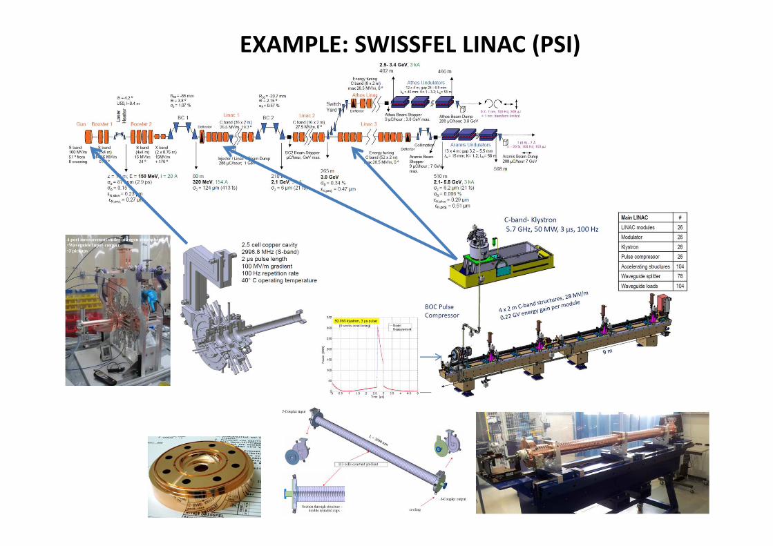
EXAMPLE: SWISSFEL LINAC (PSI)

EXAMPLES: JAPANESE XFEL (SPRING-8)
Damped C-band cavities
The most remarkable feature of
the injector is employing a
thermoionic gun (500 keV CeB6
single crystal). RF beam
manipulations with multi-stage RF
cavities are the necessary to not
degrade the initial emittance.
Thermionic gun

EXAMPLES: EUROPEAN XFEL
Frequency = 1.3 GHz
Gradient = up to 60 MV/m
Exit energy = 6.5 MeV
Cs2Te photocathode

NEW TECHNOLOGIES
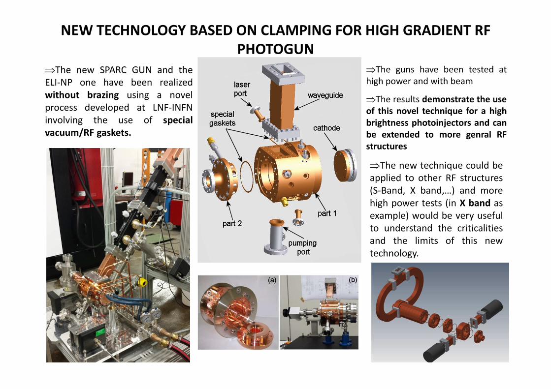
NEW TECHNOLOGY BASED ON CLAMPING FOR HIGH GRADIENT RF
PHOTOGUN
⇒The new SPARC GUN and the
ELI-NP one have been realized
without brazing using a novel
process developed at LNF-INFN
involving the use of special
vacuum/RF gaskets.
⇒The guns have been tested at
high power and with beam
⇒The results demonstrate the use
of this novel technique for a high
brightness photoinjectors and can
be extended to more genral RF
structures
⇒The new technique could be
applied to other RF structures
(S-Band, X band,…) and more
high power tests (in X band as
example) would be very useful
to understand the criticalities
and the limits of this new
technology.

DAMPED/HIGH GRADIENT/HIGH REPETITION RATE C-BAND
ACCELERATING STRUCTURES FOR THE ELI-NP LINAC⇒ The linac energy booster of the European ELI-NP proposal
foresees the use of 12, 1.8 m long, travelling wave C-Band
structures.
⇒ Because of the multi-bunch operation, the structures integrate
a very effective dipole HOM damping system to avoid beam
break-up (BBU).
⇒ An optimization of the electromagnetic and mechanical design
has been done to simplify the fabrication and to reduce their
cost.
⇒ The high power test on the first full scale structure shown the
feasibility of the 33 MV/m, 100 Hz, long RF pulse operation

REFERENCES
Hans Weise, DESY, The Electron Accelerator of the European XFEL, presentation at the European XFEL User Meeting 2011, Hamburg, Germany
Sergey Belomestnykh, Brookhaven National Laboratory, Principles of RF superconductivity, Presentation at the USPAS school, Durham, NC, 2013
Dinh Nguyen, John Lewellen and Leanne Duffy, Los Alamos National Laboratory, RF Linac for High-Gain FEL, USPAS School, 2014
Gianluigi Ciovati, Thomas Jefferson National Accelerator Facility, presentations at the USPAS School, 2015.
Jean Delayen, Thomas Jefferson National Accelerator Facility, presentations at the USPAS school, 2015
S. Di Mitri, RF Technology, USPAS school 2015
R. Carter, Review of RF power sources for particle accelerators, CAS School on Radiofrequency engineering, CERN-2005-003, 2005 and RF power
generation, CAS School on RF for accelerators, Ebeltoft, Denmark, 2010, CERN–2011–007
G. Bisoffi, Superconducting Cavities, CAS School on Radiofrequency engineering, SeeimCERN-2005-003, 2005
B. Aune et al., Superconducting TESLA cavities, PRST-AB, VOLUME 3, 092001 (2000)
J. Sekutowicz, Desy, Superconducting Linear Accelerator for the European XFEL, International Workshop on X-ray Diagnostics and Scientific
Application of the European XFELRyn, Poland, 14-17 February 2010 and Superconducting Cavities, CAS on RF for Accelerators, Ebeltoft, Denmark,
8-18 June, 2010.
H. Safa, Surface effects in SCRF cavity, CAS School on Superconductivuty and Cryogenics for accelerators and detectors, CERN-2004-008
D. Proch, RF cavity fabrication, CAS School on Superconductivuty and Cryogenics for accelerators and detectors, CERN-2004-008

H. Padamsee, Designing superconducting cavities for accelerators, CAS School on Superconductivuty and Cryogenics for accelerators and
detectors, CERN-2004-008 and Design Topics for Superconducting RF Cavities and Ancillaries, CAS School on Superconductivity for Accelerators,
Erice 2013, CERN–2014–005
R. Parodi, Couplers and HOM dampers, CAS School on Superconductivuty and Cryogenics for accelerators and detectors, CERN-2004-008
E. Jensen, CERN, Cavity basics, CAS School on RF for accelerators, Ebeltoft, Denmark, 2010, CERN–2011–007 and RF Principles and TM Mode
Cavity, SRF 2015, Whistler, 2015
Paolo Michelato, INFN Milano – LASA, Cavity Processing: EP/BCP, heat treatments, baking and clean room techniques, SRF13 Tutorials,
September 2013.
Terry Garvey, The SwissFEL Linac, Presentation at the John Adams Institute, Oxford University, 8th May, 2014.
Yujong Kim†, S. Saitiniyazi, M. Mayierjiang, M. Titberidze, T. Andrews, and C. Eckman, Performance Comparison of S-band, C-band, and X-band RF
Linac based XFELs, ICFA FLS2012 Workshop, Newport News, USA
Roger M. Jones, Wakefield suppression in high gradient linacs for lepton linear colliders, PRST-AB, 12, 104801 (2009)
T. Inagaki#, K. Shirasawa, T. Sakurai, C. Kondo, T. Ohshima, Y. Otake, and T. Shintake, OPERATION STATUS OF C-BAND HIGH-GRADIENT
ACCELERATOR FOR XFEL/SPRING-8 (SACLA), Proceedings of IPAC2011, San Sebastián, Spain.
K. Togawa,* T. Shintake, T. Inagaki, K. Onoe,† and T. Tanaka, CeB6 electron gun for low-emittance injector, PRST-AB 10, 020703 (2007)
T. Inagaki,* C. Kondo, H. Maesaka, T. Ohshima, Y. Otake, T. Sakurai, K. Shirasawa,† and T. Shintake, High-gradient C-band linac for a compact x-ray
free-electron laser facility, PRST-AB 17, 080702 (2014)
F. Löhl, J. Alex, H. Blumer, M. Bopp, H. Braun, A. Citterio, U. Ellenberger, H. Fitze, H. Joehri, T. Kleeb, L. Paly, J.-Y. Raguin,
L. Schulz, R. Zennaro, C. Zumbach, Status of the SwissFEL C-band Linac, FEL 2014 Conference, August 25-29, 2014, Basel, Switzerland
David Dowell, USPAS school, High Brightness Electron Injectors for Light Sources, 2010
K. Smolenski, I. Bazarov, B. Dunham, H. Li, Y. Li, X. Liu, D. Ouzounov, C. Sinclair, Design and Performance of the Cornell ERL DC Photoemission
Gun, AIP Conf. Proc. 1149, 1077 (2009);