
proceedings-numbered - Fakultät BWL · Markus Nüttgens , Jan Mendling (eds.) XML4BPM 2005 XML...
94
Markus Nüttgens, Jan Mendling (eds.) XML4BPM 2005 XML Interchange Formats for Business Process Management 2 nd Workshop of German Informatics Society e.V. (GI) in conjunction with the 11 th GI Conference “BTW 2005” March 01, 2005 in Karlsruhe (Germany) Proceedings
Transcript of proceedings-numbered - Fakultät BWL · Markus Nüttgens , Jan Mendling (eds.) XML4BPM 2005 XML...

Markus Nüttgens, Jan Mendling (eds.)
XML4BPM 2005
XML Interchange Formats for Business Process Management
2nd Workshop of German Informatics Society e.V. (GI) in conjunction with the 11th GI Conference “BTW 2005” March 01, 2005 in Karlsruhe (Germany)
Proceedings

Organizer
This workshop is organized by the GI Working Group “Business Process Management
with Event-Driven Process Chains (EPC)” within the GI Special Interest Group WI-
MobIS (FB-WI) in conjunction with the 11th
GI Conference “BTW 2005”.
Prof. Dr. Markus Nüttgens
Email: [email protected]
Dipl.-Wirt.-Inf. Dipl.-Kfm. Jan Mendling
Email: [email protected]
XML4BPM 2005 / XML for Business Process Management. Eds.: Markus Nüttgens, Jan
Mendling – Karlsruhe 2005.
© Gesellschaft für Informatik, Bonn 2005
The use of registered names, trademarks, etc. in this publication does not imply, even in
the absence of a specific statement, that such names are exempt from the relevant
protective laws and regulations and therefore free for general use.
2

Preface
This proceedings volume contains the papers presented at the 2nd
GI workshop XML for
Business Process Management (XML4BPM 2005) which is held in conjunction with the
11th
GI Conference “BTW 2005” taking place in Karlsruhe (Germany) from March 02 to
04, 2005. The workshop aims to discuss recent topics concerning XML based domain
and interchange formats for Business Process Management on a broad conceptual and
technical basis and in dialogue between research and industry.
Beyond the presentation of the state-of-the-art the workshop covers the concepts behind
interchange formats designed in research and industry and identifies perspectives for
integration and future research. The topics in detail include the following:
• Metamodels, schemas, and ontologies for business process modelling,
• XML-based reference models and model-driven development for BPM,
• XML-based integration and transformation in the context of BPM,
• Application of Web Services and Semantic Web technologies for BPM,
• Evaluation and comparison of competitive BPM standards,
• Procedural models in the context of XML and BPM,
• PNML, EPML, XPDL, XMI, BPEL4WS, BPSS, etc. and their application,
• Inter-organizational document exchange (e.g. XML-EDI, xCBL, etc.),
• Economic impact of XML-based standardization of BPM.
This proceedings volume includes six carefully selected papers presented at the
workshop that address different specific aspects and applications of XML-technologies
in the context of business process management. The comments of the reviewers are
reflected in a distinction between full papers and discussion papers. The full papers
cover modeling of cross-organizational business processes, Event-Driven Process Chains
and workflow pattern support, and model-driven development of web service
transactions. The discussion papers present an application from cryo-biology, process
patterns related to organizational aspects of workflows, and process model
transformation in the context of collaborative business processes.
We thank the authors, the members of the program committee, and the local organization
team of the GI Conference “BTW 2005” for their contributions to the realization of this
workshop.
Hamburg and Vienna, April 2005 Markus Nüttgens
Jan Mendling
3

Program Committee
Christoph Bussler, DERI Ireland
Peter Buxmann, TU Darmstadt, Germany
Schahram Dustdar, TU Wien, Austria
Rony Flatscher, WU Wien, Austria
Ekkart Kindler, Uni Paderborn, Germany
Frank Leymann, Uni Stuttgart, Germany
Jan Mendling (Co-Chair), WU Wien, Austria
Markus Nüttgens (Co-Chair), Uni Hamburg, Germany
Andreas Oberweis, Uni Karlsruhe (TH), Germany
Manfred Reichert, Uni Twente, The Netherlands
Andreas Winter, Uni Koblenz, Germany
Michael zur Muehlen, Stevens Institute of Technology, USA
Organization
Jan Mendling, WU Wien, Austria
Markus Nüttgens, Uni Hamburg, Germany
4
Table of Contents
Full Papers
Sonia Lippe, Ulrike Greiner, Alistair Barros
A Survey on State of the Art to Facilitate Modelling of
Cross-Organisational Business Processes.....................................................................................7
Jan Mendling, Markus Nüttgens
TowardsWorkflow Pattern Support of
Event-Driven Process Chains (EPC)...........................................................................................23
Benjamin A. Schmit, Schahram Dustdar
Model-driven Development of Web Service Transactions......................................................39
Discussion Papers
Christopher H.P. Durst, Frank R. Ihmig, Matthias Biel,
Martin Daffertshofer, Heiko Zimmermann
XML based Process Management in Cryo-Biotechnology: The ChameleonLab................55
Lucinéia Heloisa Thom, Cirano Iochpe, Bernhard Mitschang
Improving Workflow Project Quality Via Business Process
Patterns Based on Organizational Structure Aspects................................................................65
Dominik Vanderhaeghen, Sven Zang, Anja Hofer, Otmar Adam
XML-based Transformation of Business Process Models –
Enabler for Collaborative Business Process Management ......................................................81
5

6

A Survey on State of the Art to Facilitate Modelling of
Cross-Organisational Business Processes
Sonia Lippe, Ulrike Greiner, Alistair Barros
SAP Research
Karlsruhe (Germany), Brisbane (Australia)
{ sonia.lippe, ulrike.greiner, alistair.barros}@sap.com
Abstract: Interoperability is one of the current key challenges addressed by
research and industry. Tools and methodologies are emerging to enable modelling
and execution of cross-organisational business processes, and standards are being
defined using guidelines and best practice approaches. In this context we observe
the shortcoming of a comprehensive and structured state-of-the-art analysis. We
therefore define modelling requirements that derive from an analysis of various
collaborative business scenarios. Based on these requirements we evaluate and
measure relevant work in modelling of cross-organisational business processes.
Thereby we focus on the strength and weaknesses of the different approaches.
1 Introduction
For systems interoperability and execution of long running end-to-end processes,
analysts strongly argue in favour of Business Process Management (BPM) as an
emerging layer of software for building applications [Sm01][Ph03]. BPM is about
modelling, managing, and executing processes [De03]. It offers a set of technologies,
services, tools, and standards that provide for explicit process modelling and
management, and aim to integrate applications and automation. BPM is not only relevant
for inter-application integration, but also focuses on successfully managing and
executing cross-organisational business processes (CBPs). In this context, this paper
focuses especially on modelling aspects of cross-organisational business processes.
For the design and analysis of CBPs it is necessary to consider that processes are
modelled with different perspectives, e.g., from a business point of view where a CBP is
negotiated between partners or for the execution level dealing with the actual enactment
of a CBP. Existing business process modelling languages are typically limited to one
perspective. For instance, executable languages are often not comprehensible for
managers and they lack facilities for a high-level analysis of CBPs. On the other hand
CBPs modelled with languages that support analysis on business level cannot directly be
executed as they may contain non-executable information, e.g. the transportation of
goods by a truck. Furthermore the successful modelling of CBPs requires that partners
link their existing internal processes and resources to achieve an agreed interaction
model. However, white-box exposition of internal processes cannot be expected. CBP
7

modelling tools and languages need to support a mechanism that selectively hides details
of private processes, whilst providing a process-oriented interface to the outside world,
facilitating interweaving into partner processes.
Various methodologies, languages, tools, and standards are emerging to support CBP
modelling and existing approaches have been expanded to meet CBP specific modelling
requirements. However, we failed to identify an extensive analysis specifically on the
requirements associated with modelling cross-organisational interactions. Also a state of
the art analysis is required, that lists relevant topics in this area as well as evaluates how
well CBP requirements are met. This shortcoming is overcome in this paper. Existing
surveys such as [Me04] also compare business process modelling languages but in
comparison to this paper they focus on identifying a common set of metamodel concepts
contained in the languages.
In Section 2 we start with the development of a set of requirements that result from
modelling processes running not within a company, but enacting cross-organisational
interactions. The identification of those CBP specific modelling requirements is based on
the assessment of various cross-organisational business scenarios. Based on these
requirements we describe and analyse relevant state of the art work in section 3. In
section 4 we discuss the evaluation and propose a 3-level modelling approach and the
use of views to model CBPs. We conclude with a summary and an outlook on further
research issues.
2 Requirements for CBP Modelling
2.1 Analysis of Business Scenarios
Supporting CBP modelling imposes special requirements on methodologies, languages,
tools, and standards. Those requirements can only be derived as a result of an extensive
analysis of possible cross-organisational business interactions. We have gathered
collaborative business cases and requirements from the field, referring to users and
practitioners from different countries and industrial sectors. Best practice approaches
already in use (e.g., [Ro04]) as well as desired features and long-term scenarios from
market leaders and analysts have been taken into account. Precisely we have based our
requirements analysis on the following sources:
- The ATHENA project [At05]
- IV&I Min/Max Replenishment Scenario [Op05]: This project consists of an
international team supported by AIAG, OESA, and Odette. The initial business
process to be defined will be min-max, in which suppliers are allowed to view
customers’ inventory data and make decisions to cover customer build and support
internal operations.
- IDEAS Project [Id05]: Deliverable 1.2 contains various real life scenarios on cross-
enterprise interactions. For each scenario a textual description is provided together
with a graphical representation.
8

- SAP Scenario Maps [Sa04]: SAP Business Scenario Maps provide a detailed
graphical representation of key end-to-end processes for a particular industry or
cross-industry. This content is available for about 50 industry segments and 10
cross-industry areas.
Based on a detailed analysis of these CBP scenarios, we have identified a set of
requirements which should be supported to facilitate CBP modelling. These
requirements form a framework against which relevant work will be evaluated. In the
following we give a short overview and describe the requirements and build up the
framework for the evaluation of the state-of-the-art.
2.2 CBP specific requirements
The framework for requirements covers different aspects of CBP modelling. To receive
a feasible metric that can be used to evaluate the state of the art, we consider seven top-
level requirements:
- support of process abstraction concept,
- a CBP modelling framework should be offered,
- modelling of the CBP business context,
- support for modelling at the CBP design level,
- support for modelling at the CBP execution level,
- support of efficient CBP assembly,
- support of global business information schema.
These requirements contain more fine grained points, which are described below.
Process abstraction concept: CBPs are based on multiple data-sets, owned and
maintained by the different involved parties with the goal to interweave the existing
partner processes whilst creating minimal impact on the existing processes. By means of
distribution and outsourcing, a CBP indirectly connects private business processes in a
cross-enterprise business scenario [Sch02]. Thus, a suitable concept to selectively hide
details of private processes, whilst providing a process-oriented interface to facilitate the
state-oriented communication between trading partners is required. We can therefore
state as a first requirement the need for a concept which allows for abstraction of internal
processes and the creation of a selected interface to the outside world. In detail this
maps to the following requirements:
- The modelling approach should allow on one hand for protecting the internal/private
information of the partners that should not be published. Whereas on the other hand
information must be revealed to successfully create a CBP and define the desired
interaction.
- Therefore the approach must be able to represent internal/private processes and an
external/public visible abstraction of the process.
- In addition mapping between internal processes and external process views must be
enabled as well as the combination of different process abstraction to a CBP.
CBP modelling framework: Given the distinct natures of business and technical
aspects of modelling, a collaborative and integrated CBP modelling framework
incorporating the ‘best-of-breed’ techniques for the different levels of modelling – from
9

a business-level view to a technical perspective – is required. This also comprises an
appropriate tool support. A similar requirement is described in [KK02] which introduces
a metamodelling platform. The framework should fulfil the following requirements:
- The CBP framework must facilitate collaborative development of CBP
specifications by business users in the different stakeholder partners. The emphasis
of collaboration here is on the development aspect of CBP specifications. Thus,
functions such as the seamless, multi-developer partitioning of a model, support of
incomplete models, model versioning, or tracking of open issues requiring
resolution for model completion typify collaborative model development.
- Furthermore, a common environment is required to facilitate interaction of partners
and to allow for sharing context and state information related to symmetric
cooperative and collaborative processes.
- The related aspects of models must be integrated across the different techniques
supported in the framework. In other words, an integrated CBP modelling
framework is required.
- The specifications of CBPs and the modelling techniques must be captured, as far as
possible, through a highly effective graphical/visualization user interface. Where
inappropriate or not possible for a part of CBP specifications to be captured through
graphical means, the non-graphical (i.e. textual) part must be well-integrated with
the graphical part.
Business context: The modelling of the underlying business context should be
supported. The business context describes an operational business situation, including its
goals, objectives, expectations, and problems. Not all aspects of models at the business
context level will be executable (e.g. meetings, problem escalation up the organizational
hierarchy, physical transport of materials). Thereby, the following aspects should be
considered:
- The relationship between the CBP business context and CBP design model is one of
loose refinement. This is because business users determine what aspects of the
context should be automated (scoping) and how the problem-focused business
context relates to the solution-focused CBP design model (informal mapping). Thus,
it is important to support this informal, loose refinement step.
CBP design level: The CBP design level is a level which is distinct from the business
context level out of which it was designed and the platform execution level. The CBP
design level must be conceptual, independent of operational business contexts and
platform-specific implementation levels. The CBP design level is characterized by the
following requirements:
- The CBP design level must support conceptual specifications for the business level.
Therefore, they must be highly suitable for business users, have a sufficient
expressive power, and a clear (formal) semantics to avoid modelling ambiguities
and errors.
- Business users must be able to validate CBP design models through model
execution (i.e. model simulation).
CBP execution level: In addition to the CBP design level it is also important that the
approaches support modelling at the CBP execution level which is transformed out of
the CBP design level. Its purpose is to demonstrate the correctness of the design model
10

with respect to the implementation platform. The CBP execution level can be
characterized as follows:
- It must allow application and platform specific aspects of the specification to be
factored in (e.g. invocation of the application components, the implementation
choice for message channels).
- The target platform chosen must be general enough so that the demonstration of
implementation can be used to indicate how other platforms might be used. A
support of all possible target platforms must not be the goal (similar to model driven
architecture [Om05]).
Efficient CBP process assembly: This deals with a mechanism for the assembly of
CBPs through process components from private and public processes. This level
comprises the following detailed requirements:
- Partial input of the partners and input and output flow within the CBP has to be
represented. This regards the input of the partners for the process and the
relationships in between. That tackles the issue which input does one partner need
from other partners in order to fulfil its part. This point plays an important role if the
CBP output is a physical product.
- Also the information flow within the CBP has to be represented. The language must
be capable to represent the information flow between the partners, e.g. different
versions of a document. This point is much more important if the CBP output is a
service.
- A modelling language must be able to describe the CBP interfaces, esp. the relevant
information within the process interfaces, so that the CBP can run properly.
Global business information schema: A global business information schema should be
supported which provides a common reference of business messages interchanged in
cross-organisational business processes. A global business information schema may be
characterized as follows:
- Common message interchange data and formats must be available through the
schema for all CBP applications. All business documents are required to abide by
this structure in order to be supported for message interchange in CBP applications.
- The schema should also store global business object types, relationships, and
constraints for CBP applications. This will allow parties in a CBP application to
structure business messages at the conceptual (i.e. implementation independent)
level. It will also provide an independent basis for mapping to party-specific data
definitions.
- It is important that the schema also provides definitions of the specific business
objects of each party if it is necessary or whished to expose these internal data
structures to partners. The global to local mapping of business object types and
business message structures would be visible for all CBP applications or within the
application that the party is involved with. The party should nominate the level of
visibility for its exposed data definitions.
- It is important to make the system scopes of a CBP explicit to reflect the different
sensitivities of information and event flow in those scopes. One scope might be the
different parties in a CBP which essentially are part of the same organization and a
known coalition with an established degree of trust (like government agencies).
Business messages should contain the relevant data for parties within a system
11
scope. Thus, two different scopes entail different degrees of business message detail
for the parties in the scopes.
- The modelling methodologies or languages should have the ability to reflect internal
organizational constraints externally. CBP specifications must contain
organizational role requirements for undertaking CBP activities. This allows CBP
parties to understand at an external level the role context involved in undertaking a
CBP activity. The role requirement specified against a CBP activity might be used
to discover either at design or runtime a concrete binding of the activity.
3 Description and Evaluation of Related Work
In our survey we have considered several approaches dealing with CBP modelling and
enactment. For the presentation in this paper we concentrated on those approaches for
modelling of CBPs which are based on standards resp. standard proposals or are widely
used. Some approaches do not directly use XML but at least provide an XML export of
the proprietary format. In summary, the following relevant work has been considered:
- Event-Driven Process Chains (EPC) [Ho92],
- the Integrated Enterprise Modelling (IEM) method [MJ99][Sp96],
- Business Scenario Maps [Sa04],
- the Business Process Definition Metamodel1 (BPDM) [Om03a] together with the
Business Process Modeling Notation (BPMN) as a possible notation,
- the Unified Modelling Language (UML, which may also be used as a notation for
BPDM) [Om04],
- ebXML [eb04],
- RosettaNet [Ro04],
- the Business Process Modelling Language (BPML) [Bp04],
- the XML Process Definition Language (XPDL) [Wf02],
- and the Web Services Business Process Execution Language (WS-BPEL) [An03]
in combination with the Web Services Choreography Definition Language (WS-
CDL) [W04].
For the evaluation of the state of the art for facilitating CBP modelling we have created a
schema in which we rank how well a particular approach meets the requirements
specified in section 2. We classify a requirement as fully supported if the approach
supports this requirement without any restrictions. A requirement is partly supported if
some but not all of the aspects identified in section 2 are supported. Not supported
applies if an approach does not address a requirement at all.
The results of the state of the art analysis are summarized in Table 1. For a clearer
presentation we only added the top-level requirements in the table. In the following we
shortly describe the different approaches and explain the findings outlined in Table 1.
1 Note, that we have considered the current submissions as the standardization will not be finished until the end
of 2005.
12
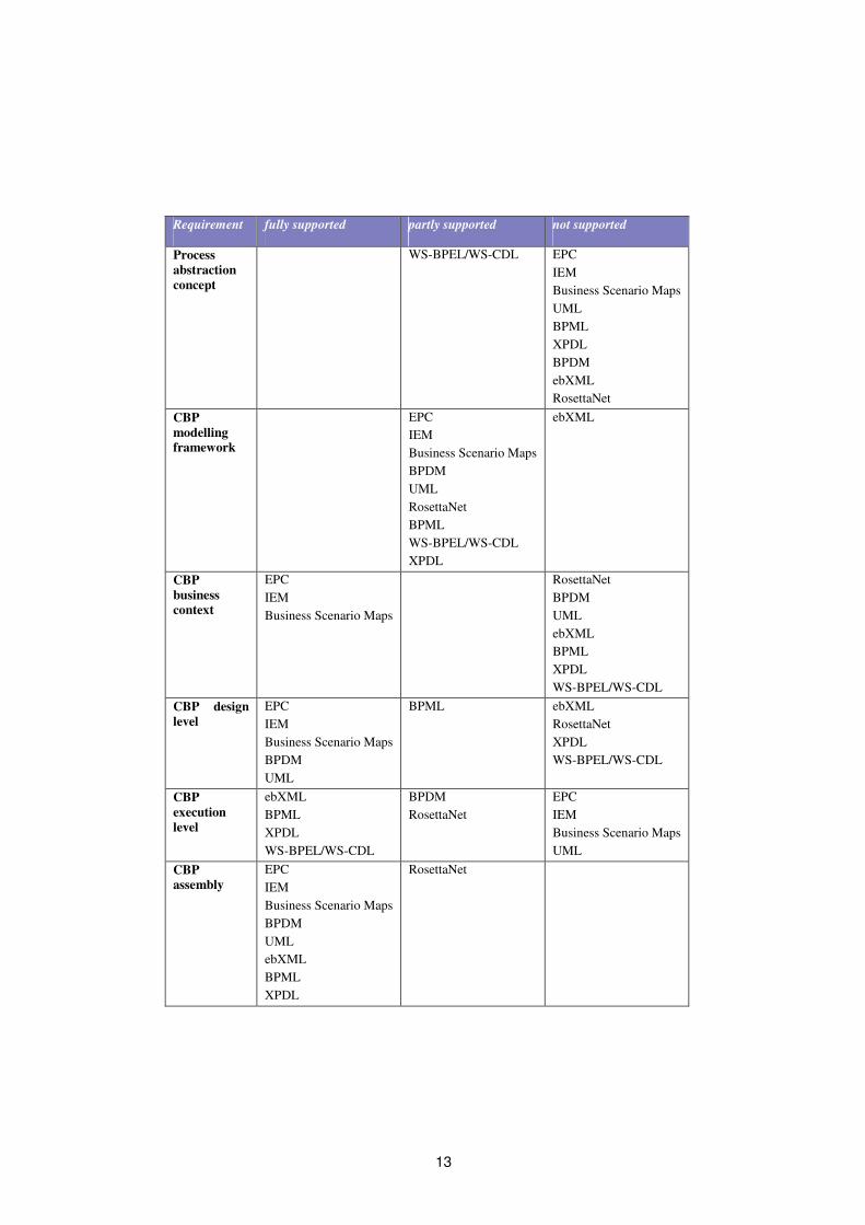
Requirement fully supported partly supported not supported
Process
abstraction
concept
WS-BPEL/WS-CDL EPC
IEM
Business Scenario Maps
UML
BPML
XPDL
BPDM
ebXML
RosettaNet
CBP
modelling
framework
EPC
IEM
Business Scenario Maps
BPDM
UML
RosettaNet
BPML
WS-BPEL/WS-CDL
XPDL
ebXML
CBP
business
context
EPC
IEM
Business Scenario Maps
RosettaNet
BPDM
UML
ebXML
BPML
XPDL
WS-BPEL/WS-CDL
CBP design
level
EPC
IEM
Business Scenario Maps
BPDM
UML
BPML ebXML
RosettaNet
XPDL
WS-BPEL/WS-CDL
CBP
execution
level
ebXML
BPML
XPDL
WS-BPEL/WS-CDL
BPDM
RosettaNet
EPC
IEM
Business Scenario Maps
UML
CBP
assembly
EPC
IEM
Business Scenario Maps
BPDM
UML
ebXML
BPML
XPDL
RosettaNet
13

Requirement fully supported partly supported not supported
WS-BPEL/WS-CDL
Global
Business
Information
Schema
EPC
Business Scenario Maps
ebXML
IEM
BPDM
UML
RosettaNet
BPML
XPDL
WS-BPEL/WS-CDL
Table 1: Evaluation of relevant work.
Regarding the first requirement, the support of a process abstraction, only WS-BPEL (a
merger of IBM WSFL and Microsoft XLANG) partially meets this requirement as it has
the notion of “abstract processes” that can be used to model abstract views of business
processes. To define CBPs WS-CDL may be used in combination with WS-BPEL as it
provides a global, message-oriented view of a process involving multiple Web services.
Some of the other approaches offer constructs which might be used to model process
views (for instance, UML 2.0 which introduces some new features for modelling
business processes, e.g. interaction and composition structure diagrams) but they do not
support the concept explicitly. In particular, there is no support for generation of views,
mapping of views and private processes or interweaving of process abstractions to create
CBPs.
With respect to the requirement of a CBP modelling framework nearly all approaches
offer tool support, mainly with graphical user interfaces. However, they often only
support either the business/CBP design level (e.g. EPC, IEM, or Business Scenario
Maps) or the execution level (e.g. BPML, XPDL, WS-BPEL) or modelling of platform
independent control flow2. The latter is supported by BPDM which defines an abstract
metamodel for business process definition. As such this metamodel provides a common
abstraction for multiple business process or workflow definition languages. We fail to
identify an approach that gives a comprehensive modelling support on all levels.
Regarding the modelling of business context EPCs, IEM, and Business Scenario Maps
are well suited as they focus on modelling of CBPs from the business level perspective
and provide methods to capture business context. For instance, EPCs depict complex
processes by describing the logical activity flow through a sequence of function, event,
and logic operators. These are typically very high-level and may also capture business
goals, expectations, or organisational hierarchies. In contrast to that BPDM, UML,
ebXML, BPML, XPDL, and WS-BPEL/WS-CDL do not support the modelling of
business context. They focus on modelling only business processes, data exchange or
2 as in model driven architectures (MDA) [Om05]
14

process definition exchange. RosettaNet defines common business procedures which are
independent of the concrete context
Approaches that deal with process modelling on the business level (EPCs, IEM,
Business Scenario Maps) do fully support the CBP design level. This also holds for
BPDM and UML as they aim at offering a platform independent process model which is
well suited for the design level. BPML already takes into account the execution level by
regarding events and messages but still can be viewed as offering design level support.
In contrast to that the strength of ebXML, RosettaNet, XPDL, and WS-BPEL/WS-CDL
is on modelling CBPs on the execution level. Thus, they offer only limited or no support
for modelling on the CBP design level but good support for the CBP execution level.
An efficient CBP assembly considering CBP internal data flow and CBP interface
descriptions is well supported by nearly all approaches. RosettaNet, a consortium of
major information technology, electronic components, semiconductor manufacturing,
telecommunications and logistics companies, aims at creating and implementing
industry-wide, open e-business process standards. Thus, it offers only limited support for
CBP assembly as it focuses on the definition of common business procedures and
reflects data flow only partially.
A global business information schema contains common messages, business objects,
scopes for defining the visibility of business objects, and support of a role concept.
Furthermore, an efficient mapping between business objects should be supported. None
of the investigated approaches meets all of these requirements. However, each approach
meets some of them to a certain extent. For instance, approaches that are well suited for
the CBP design level (e.g. EPCs and IEM) offer role concepts and definition of scopes.
For instance, ebXML, a project to standardize the secure exchange of business data
using XML, offers common data types used in CBPs. WS-BPEL supports amongst other
things the modelling of data exchanged in CBPs. However, a comprehensive support for
mapping private objects to common business objects and mapping of business objects on
each other (e.g. with additional semantic information) is not addressed in any of the
approaches.
4 Discussion of the State-of-the-Art
From table 1 we observe that none of the investigated approaches supports all
requirements that should be addressed by methodologies, languages, tools, and standards
facilitating the modelling of CBPs. Looking at the strengths and weaknesses of the
different approaches in terms of which requirements they fully or partially support, the
following can be concluded:
- Sufficient support for CBP assembly in most of the languages: We observe
sufficient support for representing information flow between different partners in
most approaches, except RosettaNet which has its main focus on process
descriptions.
15

- Insufficient support for modelling of process abstraction and linking up
internal processes to CBPs: Even though CBPs can be modelled and interfaces
between the partners can be specified, we observe a shortcoming in explicitly
linking up internal processes to CBPs. None of the discussed approaches offers a
suitable mechanism to link up private processes into CBPs, enabling information
hiding at the same time. We propose a suitable concept to overcome this
shortcoming further down in this chapter.
- Need for a collaborative and integrated modelling framework comprising all levels of abstraction: Taking into account the evaluation of languages concerning
the requirements of supporting business context, the CBP design level and the CBP
execution level, we observe that each language, standard and tool has a strength in
either of those modelling levels. We therefore propose a 3-level modelling
approach, incorporating the best techniques for each level.
Insufficient support for linking up internal processes to CBPs: A systematic way is
required, that allows partners to selectively expose internal information and interweave
process steps to CBPs. As promising concept in this context we propose the conceptual
model of process views, where process views are introduced as an additional layer above
the private processes of an organisation [SL01]. Private processes contain data that must
not be revealed by default whereas process views provide an abstraction of the private
process that is sufficient to coordinate internal actions with activities of external trading
partner(s) [SO04]. This modelling concept is depicted in Organisation 1 in Fig. 1. A
particular interaction may require involved partners to adapt for the purpose of the
communication. This adaptation can not necessarily be reflected in the partners' private
(internal) business processes without inflicting their ability to interact with other partners
in a different context. Imagine an automotive supplier that is providing parts to two
different car manufacturers that prescribe a particular sequence of interaction. The
supplier’s goal will be to run the same internal process and still to collaborate with both
manufacturers. To enable this, process-oriented abstraction needs to be modelled and
tightly bound to the corresponding private business process. Therefore based on one
private process, different views can be generated (cp. Organisation 3) and thus reflect the
specific requirements of multiple interactions. CBPs are then constructed by
interweaving process views of different organisations (cp. CBP 3 in Fig. 1). Using
different views of the same internal processes, organisations are able to interact in a
different context without changing the internal process (cp. Organisation 3 in Fig. 1).
The concept of creating views to provide abstract information about internal processes
was first introduced by Liu and Shen in 2001[LS01]. It is derived from views as they are
used in database systems and the authors present a formal model of processes and extend
it to virtual process views providing transformation rules. While the views in the initial
work are only used to provide necessary information about processes to other company
internal departments, they extend their work in [SL01] for the purpose of CBPs. Parallel
to this work Chiu et al. introduce workflow views to control visibility of internal
processes and to enable inter-operability of e-services [Ch02a]. The main focus in this
work is on combining views of different partners to composite e-services (CBPs) and the
implementation of the views with contemporary Web services. A mapping mechanism to
ensure the coupling between private processes and views in all circumstances is not
16

provided. Schulz et al. take up the concept of views, discuss it in the context of mediated
and un-mediated communication and formalize the dependencies between private
processes, process views and CBPs [Sch02][SO01][SO04].
Figure 1: Dependencies between private processes, process views and CBPs.
Need for a collaborative and integrated modelling framework comprising all levels
of abstraction: Motivated by the requirements we identify three levels on which CBP
models are created (cp. Fig. 2):
- Business level: Business processes: This level represents the business view on the
cooperation and the cross-organisational process that describes the interaction of the
partners. The CBPs modelled on this level are not executed. This level mainly
supports the perspective of a business analyst.
- Business level: Technical processes: This level provides a more detailed view on
the CBP representing the complete control flow of the process. For instance, single
tasks and messages exchanged are modelled on this level. However, the control flow
is specified in a platform independent manner, so that the CBP models at this level
are still not executable by a business process engine.
- Execution level: Executable processes: The CBP model on this level contains
platform specific interaction information and may be executed in an appropriate
execution engine. Platform specific information is e.g. the concrete message formats
sent or received during CBP execution or the transport protocols used.
17
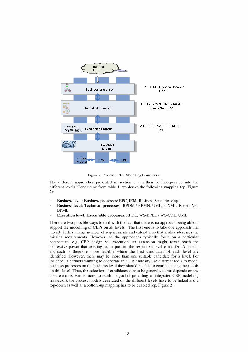
Figure 2: Proposed CBP Modelling Framework.
The different approaches presented in section 3 can then be incorporated into the
different levels. Concluding from table 1, we derive the following mapping (cp. Figure
2):
- Business level: Business processes: EPC, IEM, Business Scenario Maps
- Business level: Technical processes: BPDM / BPMN, UML, ebXML, RosettaNet,
BPML
- Execution level: Executable processes: XPDL, WS-BPEL / WS-CDL, UML
There are two possible ways to deal with the fact that there is no approach being able to
support the modelling of CBPs on all levels. The first one is to take one approach that
already fulfils a large number of requirements and extend it so that it also addresses the
missing requirements. However, as the approaches typically focus on a particular
perspective, e.g. CBP design vs. execution, an extension might never reach the
expressive power that existing techniques on the respective level can offer. A second
approach is therefore more feasible where the best candidates of each level are
identified. However, there may be more than one suitable candidate for a level. For
instance, if partners wanting to cooperate in a CBP already use different tools to model
business processes on the business level they should be able to continue using their tools
on this level. Thus, the selection of candidates cannot be generalized but depends on the
concrete case. Furthermore, to reach the goal of providing an integrated CBP modelling
framework the process models generated on the different levels have to be linked and a
top-down as well as a bottom-up mapping has to be enabled (cp. Figure 2).
18

Furthermore, to provide a concept that allows the partners to control the visibility of
their private processes, the concept of process views should accomplish the 3-level
approach. It is applicable on each of the three levels. To integrate the view approach
with the 3-level modelling framework, two kinds of mappings between process
representations are needed: a horizontal mapping between private process, process view,
and CBP on each level as well as a vertical mapping between CBP models on different
levels. Future work should investigate on these mapping requirements.
5 Conclusion and Outlook
Often business processes not only involve internal resources of an organisation, but take
place between multiple independent partners crossing organisational boundaries. These
cross-organisational business processes are emergently of interest for research and
industry. In the context of modelling CBPs, we derived comprehensive requirements
from CBP scenarios and best practice approaches. The requirements can be summarized
in the following high-level requirements:
- support of process abstraction concept,
- a CBP modelling framework should be offered,
- modelling of the CBP business context,
- support for modelling at the CBP design level,
- support for modelling at the CBP execution level,
- support of efficient CBP assembly,
- support of global business information schema.
Based on these requirements, we have conducted a state of the art survey which allows
us to draw the following conclusions. Most of the languages offer sufficient support for
CBP assembly. However, they provide insufficient support for modelling of process
abstraction and linking up internal processes to CBPs and do not offer a collaborative
and integrated modelling framework comprising all levels of abstraction. Thus, a 3-level
approach should be used to allow for a comprehensive modelling of CBPs taking into
account different perspectives. We have identified the following levels: Business Level –
Business Processes, Business Level – Technical Processes, and Execution Level –
Executable Processes. As no modelling technique is able to support all levels, we argue
that it is necessary to identify the ‘best of breed’ for each level. Therefore a mapping
between the CBP models created on the different levels is necessary and should be
supported by tools. This allows bridging the gaps between different existing approaches.
Additionally, to provide a concept that allows the partners to control the visibility of
their private processes, the concept of process views should accomplish the 3-level
approach by introducing an abstraction level between the private processes and the
views.
Future research issues should address how the mappings between the CBP models on the
three levels can be performed efficiently and how the concept of process views can be
represented in the investigated approaches on the different levels. This will also help to
identify which approaches should be selected as ‘best of breed’ on the different levels.
19

Acknowledgements
The work published in this paper is (partly) funded by the E.C. through the Athena IP
(http://www.athena-ip.org). It does not represent the view of E.C. or the ATHENA
consortium, and authors are solely responsible for the paper's content.
References
[An03] Andrews, T. et al.: Business Process Execution Language for Web Services, Version 1.1.
May 2003.
[At05] ATHENA project. Information available at http://www.athena-ip.org
[Bp04] BPML. Available at http://www.bpmi.org/bpml.esp
[Ch02a] Chiu, D.K.W., Karlapalem, K., Li, Q., Kafeza, E.: Workflow view based e-contracts in a
cross-organisational e-services environment. Distributed and Parallel Databases 12(2-3),
Dordrecht, 2002; pp. 193-216.
[De03] Delphi Group: BPM 2003. Market Milestone Report. A Delphi Group White Paper.
2003.
[eb04] ebXML. Available at http://www.ebxml.org
[Ho92] Horrmann, W., Kirsch, J., Scheer, A.-W.: Modellierung mit Ereignisgesteuerten
Prozeßketten: Methodenhandbuch; Stand: Dezember 1992. In: Scheer, A.-W. (ed.):
Veröffentlichungen des Instituts für Wirtschaftsinformatik, no. 101, Saarbrücken, 1992.
[Id05] IDEAS project. Available at: http://www.ideas-roadmap.net/webpage/Phps/scheme.php
[KK02] Karagiannis, D., Kühn, H.: Metamodelling Plattforms. Proc. of EC-Web 2002 – Dexa
2002, France, 2002; p. 182.
[LS01] Liu, D.-R., Shen, M.: Modeling workflows with a process-view approach. Proceedings
of Seventh International Conference on Database Systems for Advanced Applications,
Hong Kong, 2001, pp. 260-267.
[Me04] Mendling, J., Neumann, G., Nüttgens, M.: A Comparison of XML Interchange Formats
for Business Process Modelling. Proc. of EMISA’04, 2004; p.129-140.
[MJ99] Mertins, K., Jochem, R.: Quality-Oriented Design of Business Processes. Kluwer
Academic Publishers, Boston, 1999.
[Om03a] OMG: Business Process Definition Metamodel – Request for Proposal. OMG
Document: bei/2003/01-06.
[Om03b] OMG: XML Metadata Interchange. Available at
http://www.omg.org/technology/documents/formal/xmi.htm
[Om04] OMG: Unified Modeling Language. Available at http://www.uml.org
[Om05] OMG: Model Driven Architecture. Available at http://www.omg.org/mda/[Op05] Available at: http://www.openapplications.org/downloads/meetings/20040817-19-
Detroit/2-Wednesday/1975,1,Project Definition
[Ph03] Phifer, G., Hayward, S., Flint, D.: Technologies That Enable Business Process Fusion.
Report by Gartner. October 2003.
[Ro04] RosettaNet. Available at http://www.rosettanet.org
[Sa04] SAP. SAP business maps. Technical report, SAP AG,
http://www.sap.com/solutions/businessmaps/c-businessmaps, 2004.
[Sch99] Scheer, A.-W.: ARIS – Business Process Modeling, 2nd. ed. Berlin, 1999.
[Sch02] Schulz, K.. Modelling and Architecting of Cross-Organisational Workflows. PhD thesis,
The School of Information Technology and Electrical Engineering, The University Of
Queensland, Australia, 2002.
20

[SO01] Schulz, K., Orlowska, M.E.: Architectural Issues for Cross-Organisational B2B
Interactions. Proc. International Conference on Distributed Computing Systems,
Workshop, 2001; p. 79-87.
[SO04] Schulz, K.A., Orlowska, M.E.: Facilitating cross-organisational workflows with a
workflow view approach. Data & Knowledge Engineering 51(1),2004; p. 109-147.
[SL01] Shen M.X., Liu D.R.: Coordinating interorganizational workflows based on process-
views. Database and Expert Systems Application Lecture Notes in Computer Science,
Berlin, 2001; pp. 274-283.
[Sm01] Smith, H., Neal, D., Ferrara, L., Hayden, F.: The Emergence of Business Process
Management. A Report by CSC’S Research Service. Version 0.1, January 2001.
[Sp96] Spur, G., Mertins, K., Jochem, R.: Integrated Enterprise Modelling, Berlin Wien Zürich,
Beuth, 1996.
[W04] W3C: Web Services Choreography Description Language Version 1.0. October 2004.
[Wf02] WfMC: Workflow Process Definition Interface – XML Process Definition Language,
v.1.0. WfMC document number WFMC-TC-1025, 2002.
21

22
Towards Workflow Pattern Support of
Event-Driven Process Chains (EPC)
Jan Mendling1, Gustaf Neumann1, and Markus Nuttgens2
1Vienna University of Economics and BA
Augasse 2-6, A-1090 Wien, Austria
{firstname.lastname}@wu-wien.ac.at
2Hamburg University of Economics and Politics
Von-Melle-Park 9, D-20146 Hamburg, Germany
Abstract: The 20 workflow patterns proposed by van der Aalst et al. provide a com-prehensive benchmark for comparing process modelling languages. In this paper, wepresent a workflow pattern analysis of Event-Driven Process Chains (EPCs) which isnovel in its degree of detailing. Building on this analysis, we propose three extensionsto EPCs in order to provide for workflow pattern support. These are the introductionof the so-called empty connector; inclusion of multiple instantiation concepts; and acancellation construct. The latter two are inspired by YAWL. Furthermore, describehow these extensions can be represented in EPC Markup Language (EPML).
1 Introduction
The 20 workflow patterns gathered by van der Aalst, ter Hofstede, Kiepuszewski and Bar-
ros [vdAtHKB03] are well suited for analyzing different workflow languages: workflow
researchers can reference to these control flow patterns in order to compare different pro-
cess modelling techniques. This is of special importance considering the heterogeneity of
process modelling languages (see e.g. [MNN04]). Building on the pattern analysis and
on the insight that no language provides support for all patterns, van der Aalst and ter
Hofstede have defined a new workflow language called YAWL [vdAtH05]. YAWL takes
workflow nets [vdA97] as a starting point and adds non-petri-nets constructs in order to
support each pattern (except implicit termination) in an intuitive manner.
Besides Petri nets, Event-Driven Process Chains (EPC) [KNS92] are another popular tech-
nique for business process modelling. Yet, their focus is rather related to semi-formal pro-
cess documentation than formal process specification, e.g., the SAP reference model has
been defined using EPC business process models [KM94]. The debate on EPC semantics
(see e.g. [Ri00, NR02, vdADK02]) has recently inspired the definition of a mathematical
23

framework for a formalization of EPCs in [Ki04]. As a consequence, we argue that work-
flow pattern support can also be achieved by starting with EPCs instead of Petri nets. This
paper presents a detailed workflow pattern analysis of EPCs (Section 2). In particular,
we highlight the non-local semantics of the XOR-join, and its implications for workflow
pattern support. Furthermore, we illustrate three extensions of EPCs that are sufficient to
provide for direct support of the 20 workflow patterns reported in [vdAtHKB03] (Section
3). We present our findings in an informal manner using business process models. They
represent requirements for an extended version of EPCs that we refer to as yEPCs. The
letter y is a tribute to YAWL and stresses workflow pattern support of yEPCs. As EPCs
are frequently used for business process modelling, we expect the extension of EPCs not
only to be interesting for the research community, but also useful for the modelling prac-
tice. Finally, we discuss how EPC Markup Language (EPML) can be extended in order to
capture yEPCs syntactically (Section 4). After a survey on related work (Section 5), we
give a conclusion and an outlook on future research (Section 6).
2 Workflow Pattern Analysis of EPCs
In this section we will consider the EPC control flow semantics of Kindler [Ki04]. They
basically reflect the ideas of Nuttgens/Rump [NR02] and Keller/Nuttgens/Scheer [KNS92].
These semantics have been implemented in the simulation tool EPC Tools [CK04]. Instead
of presenting them in a formal way, we discuss how EPCs can be used to model the work-
flow patterns (WP) presented in [vdAtHKB03]. For a formal definition refer to [Ki04].
Workflow Pattern 1: Sequence
A B
Figure 1: EPC Representation of WP1
Figure 1 shows an EPC model of workflow pattern 1 (sequence). In EPCs each activity or
task is modelled as a so-called function. Such functions are symbolized by rounded rect-
angles. Functions can be connected by so-called events symbolized as hexagons. Events
represent pre-requisites for a subsequent function, i.e., the event must have occurred before
the following function may be executed. Furthermore, completed functions trigger events
which may be pre-requisite for other functions. The alternation of events and functions
defines a business process which also explains the name “Event-Driven” Process Chain
(EPC). In Figure 1 function A triggers an event which is the pre-requisite of function B
defining a sequence of activities as described by workflow pattern 1.
24

Workflow Pattern 2 and 3: Parallel Split and Synchronization
(b)(a)
A
B
C
D
B
C
D
E
Figure 2: EPC Representation of (a) WP2 with AND split and (b) WP3 with AND join
EPCs define a restriction on the number of incoming and outgoing arcs of events and func-
tions. Each function must have exactly one incoming and one outgoing arc, each event at
most one incoming and one outgoing arc. In order to allow for complex routing of control
flow so-called connectors are introduced. A connector may have one incoming and mul-
tiple outgoing arcs (split) or multiple incoming and one outgoing arc (join). Furthermore,
each connector is mapped to one of the three connector types AND, OR, or XOR. Connec-
tors can be used to define a partial order of functions. Figure 2 (a) illustrates the application
of an AND split connector to achieve control flow behavior as defined by workflow pattern
2 (parallel split). That means after function A all the three subsequent functions B, C, and
D are activated to be executed concurrently. The connector is represented by a circle. The
and-symbol ∧ indicates its type. Connectors have no influence on the alternation of events
and functions (see e.g. [NR02, MN03a]). That means, for example, that an event is always
followed by a function no matter if there are no, one, or more connectors between them.
Figure 2 (b) shows the AND connector as a join. Each of the functions B, C, and D have
to be completed before E can be executed. The AND join synchronizes the parallel threads
of execution just as described by workflow pattern 3 (synchronization). The symbols for
AND split and AND join are the same. They can only be distinguished by the cardinality
of incoming and outgoing arcs.
Workflow Pattern 4 and 5: Exclusive Choice and Simple Merge
Pattern 4 (exclusive choice) describes a point in a process where a decision is made to
continue with one of multiple alternative branches. This situation can be modelled with
the XOR split connector of EPCs, compare Figure 3 (a). After function A has completed,
a decision is taken to continue with one of functions B, C, and D. Figure 3 (b) shows the
XOR join that precisely captures the semantics of pattern 5. There has been a debate on
the non-local semantics of the XOR join. While Rittgen [Ri00] and Van der Aalst [vdA99]
proposes a local interpretation, recent research agrees upon non-local semantics (see e.g.
25
(b)(a)
A
B
C
D
B
C
D
E
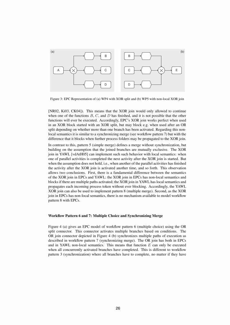
Figure 3: EPC Representation of (a) WP4 with XOR split and (b) WP5 with non-local XOR join
[NR02, Ki03, CK04]). This means that the XOR join would only allowed to continue
when one of the functions B, C, and D has finished, and it is not possible that the other
functions will ever be executed. Accordingly, EPC’s XOR join works perfect when used
in an XOR block started with an XOR split, but may block e.g. when used after an OR
split depending on whether more than one branch has been activated. Regarding this non-
local semantics it is similar to a synchronizing merge (see workflow pattern 7) but with the
difference that it blocks when further process folders may be propagated to the XOR join.
In contrast to this, pattern 5 (simple merge) defines a merge without synchronization, but
building on the assumption that the joined branches are mutually exclusive. The XOR
join in YAWL [vdAtH05] can implement such such behavior with local semantics: when
one of parallel activities is completed the next activity after the XOR join is started. But
when the assumption does not hold, i.e., when another of the parallel activities has finished
the activity after the XOR join is activated another time, and so forth. This observation
allows two conclusions. First, there is a fundamental difference between the semantics
of the XOR join in EPCs and YAWL: the XOR join in EPCs has non-local semantics and
blocks if there are multiple paths activated; the XOR join in YAWL has local semantics and
propagates each incoming process token without ever blocking. Accordingly, the YAWL
XOR join can also be used to implement pattern 8 (multiple merge). Second, as the XOR
join in EPCs has non-local semantics, there is no mechanism available to model workflow
pattern 8 with EPCs.
Workflow Pattern 6 and 7: Multiple Choice and Synchronizing Merge
Figure 4 (a) gives an EPC model of workflow pattern 6 (multiple choice) using the OR
split connector. This connector activates multiple branches based on conditions. The
OR join connector depicted in Figure 4 (b) synchronizes multiple paths of execution as
described in workflow pattern 7 (synchronizing merge). The OR join has both in EPCs
and in YAWL non-local semantics. This means that function E can only be executed
when all concurrently activated branches have completed. This is different to workflow
pattern 3 (synchronization) where all branches have to complete, no matter if they have
26
(b)(a)
A
B
C
D
B
C
D
E
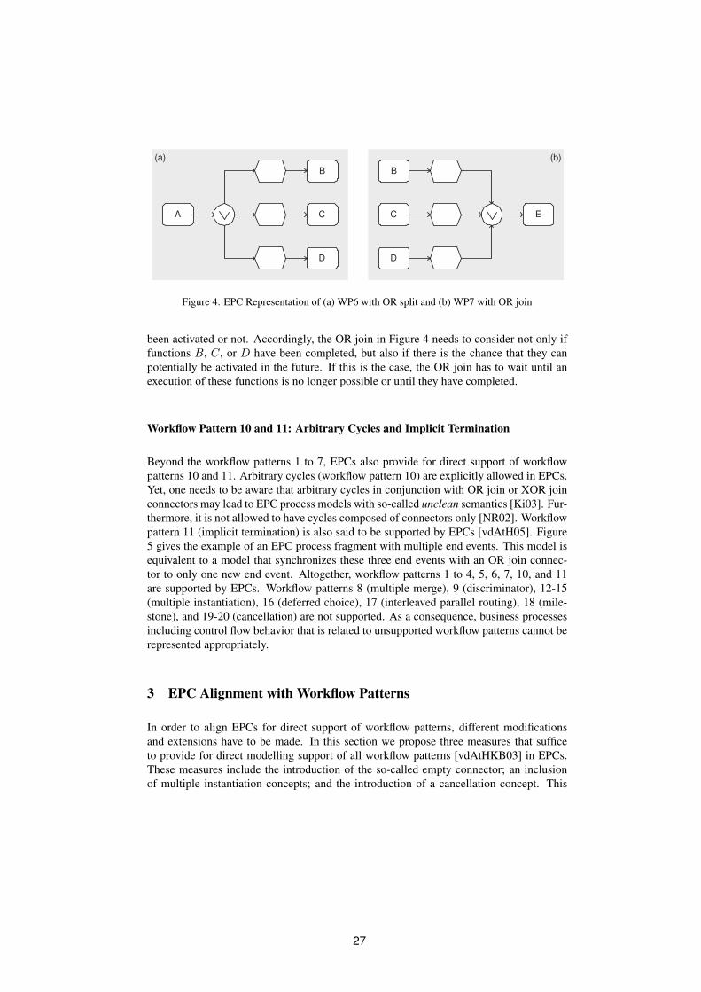
Figure 4: EPC Representation of (a) WP6 with OR split and (b) WP7 with OR join
been activated or not. Accordingly, the OR join in Figure 4 needs to consider not only if
functions B, C, or D have been completed, but also if there is the chance that they can
potentially be activated in the future. If this is the case, the OR join has to wait until an
execution of these functions is no longer possible or until they have completed.
Workflow Pattern 10 and 11: Arbitrary Cycles and Implicit Termination
Beyond the workflow patterns 1 to 7, EPCs also provide for direct support of workflow
patterns 10 and 11. Arbitrary cycles (workflow pattern 10) are explicitly allowed in EPCs.
Yet, one needs to be aware that arbitrary cycles in conjunction with OR join or XOR join
connectors may lead to EPC process models with so-called unclean semantics [Ki03]. Fur-
thermore, it is not allowed to have cycles composed of connectors only [NR02]. Workflow
pattern 11 (implicit termination) is also said to be supported by EPCs [vdAtH05]. Figure
5 gives the example of an EPC process fragment with multiple end events. This model is
equivalent to a model that synchronizes these three end events with an OR join connec-
tor to only one new end event. Altogether, workflow patterns 1 to 4, 5, 6, 7, 10, and 11
are supported by EPCs. Workflow patterns 8 (multiple merge), 9 (discriminator), 12-15
(multiple instantiation), 16 (deferred choice), 17 (interleaved parallel routing), 18 (mile-
stone), and 19-20 (cancellation) are not supported. As a consequence, business processes
including control flow behavior that is related to unsupported workflow patterns cannot be
represented appropriately.
3 EPC Alignment with Workflow Patterns
In order to align EPCs for direct support of workflow patterns, different modifications
and extensions have to be made. In this section we propose three measures that suffice
to provide for direct modelling support of all workflow patterns [vdAtHKB03] in EPCs.
These measures include the introduction of the so-called empty connector; an inclusion
of multiple instantiation concepts; and the introduction of a cancellation concept. This
27

A
B
C
D End 3
End 2
End 1
Figure 5: EPC Representation of WP11 Implicit Termination
differs from Petri net extensions that were needed to define YAWL [vdAtH05]: Petri nets
also had to be extended with multiple instantiation and cancellation concepts, but they
lacked advanced synchronization patterns. EPCs, in contrast, lack state-representation.
Furthermore, it should be mentioned that these modifications have no impact on the va-
lidity of existing EPC models, this means that valid EPCs according to the definitions in
[KNS92, NR02, Ki03] are still valid with respect to this new class of EPCs. We refer
to this extended class as yEPCs with the letter y stemming from YAWL, the workflow
language that inspired this research.
3.1 The Empty Connector
As mentioned above, EPCs cannot represent state-based workflow patterns. This short-
coming can be resolved by introducing a new connector type that we refer to as the empty
connector. This connector is represented by a cycle, just like the other connectors, but
without any symbol inside. Semantically, the empty connector represents a join or a
split without imposing a rule. We will illustrate its behavior by giving EPCs that use this
empty connector to model workflow patterns 16, 8, 17, and 18. In the following we inter-
pret events similar to states. Note that the association of EPC events with states follows
most research contributions on EPC formalization (see e.g. [KNS92, Ru99, Ri00, NR02]).
Kindler, who uses arcs to represent states of an EPCs [Ki03], mentions that his choice
was motivated rather by a straight forward presentation of his ideas than by semantical
considerations. The tokens that capture the state of an EPC are called process folders or
just folder [Ru99, NR02].
Workflow Pattern 16 and 8: Deferred Choice and Multiple Merge
Figure 6 (a) illustrates the application of the empty split connector to represent workflow
pattern 16 (deferred choice): after function A has completed, a folder is added to the
subsequent event. The empty split represents that this folder may be picked up by any of
28

(a) (b)
B
A
D
C
B
C
D
E
Figure 6: yEPC Representation of (a) WP16 Deferred Choice and (b) WP8 Multiple Merge
the subsequent function. Accordingly, the input pre-conditions of all three functions B,
C, and D are satisfied. Yet, the first of these functions to be activated consumes the folder
and by this means deactivates the other functions. Figure 6 (b) shows a process model for
workflow pattern 8 (multiple merge). As we have argued in Section 2, there is no support
in EPCs for the simple merge pattern due to the non-local semantics of the EPC XOR join
connector. An empty join connector can be used to fix this problem. This represents that
after each completion of B, C, or D a new folder is added to the pre-condition event of
E. Yet, it needs to be mentioned that a design choice has to be made between a multi-
set state representation as described e.g. in [NR02] and a simple set representation as
specified in e.g. [Ki03]. The multi-set variant would consume further folders of C and D
even if B had been executed and E not yet started. The simple set semantics would block
incoming folders until the execution of E had consumed the folder on the event. The same
mechanism can be used to implement workflow pattern 8 (multiple merge).
Workflow Pattern 17: Interleaved Parallel Routing
B
A mutex
C
E
pre-C
pre-B post-B
post-C
Figure 7: yEPC Representation of WP 17 Interleaved Parallel Routing
29
Empty connectors can also be used for other state-based workflow patterns. Figure 7
shows the process model of pattern 17 (interleaved parallel routing) following the ideas
presented in [vdAtHKB03]. The event at the center of the model manages the sequential
execution of functions B and C in arbitrary order. It corresponds to the “mutual exclusion
place (mutex)” introduced in [vdAtHKB03]. The AND-split after function A adds a folder
to this mutex event via an empty connector. The AND-joins before the functions B and
C consume this folder and put it back to the mutex event afterwards. Furthermore, they
consume the individual folders in pre-B and pre-C, respectively. These events control that
each function of B and C is executed only once. After both have been executed, there are
folders in post-B, post-C, and mutex. Accordingly, E can be started. In [Ro95] sequential
split and join operators are proposed to describe control flow behavior of workflow pattern
17. Yet, it is no clear what the formal semantics of these operators would be when these
operators are not used pairwise.
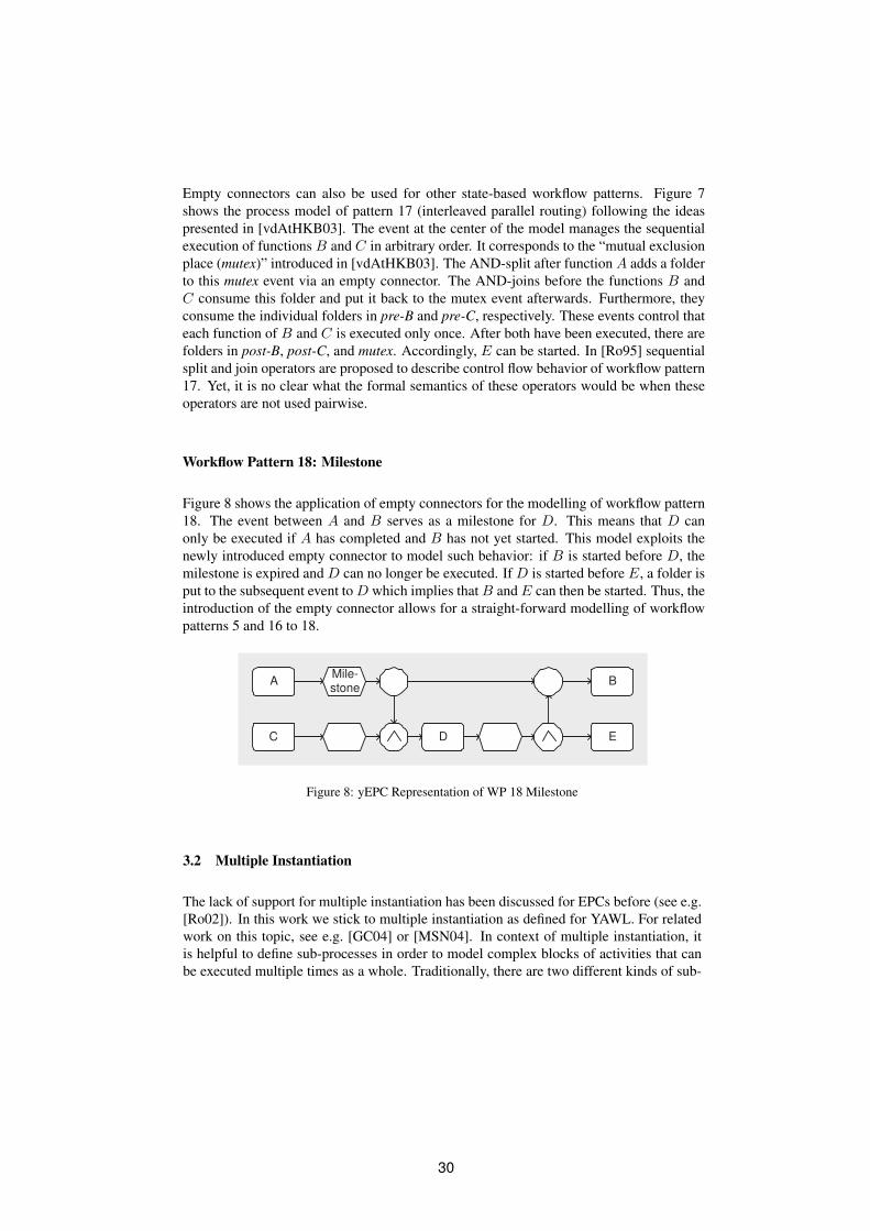
Workflow Pattern 18: Milestone
Figure 8 shows the application of empty connectors for the modelling of workflow pattern
18. The event between A and B serves as a milestone for D. This means that D can
only be executed if A has completed and B has not yet started. This model exploits the
newly introduced empty connector to model such behavior: if B is started before D, the
milestone is expired and D can no longer be executed. If D is started before E, a folder is
put to the subsequent event to D which implies that B and E can then be started. Thus, the
introduction of the empty connector allows for a straight-forward modelling of workflow
patterns 5 and 16 to 18.
AMile-stone
B
DC E
Figure 8: yEPC Representation of WP 18 Milestone
3.2 Multiple Instantiation
The lack of support for multiple instantiation has been discussed for EPCs before (see e.g.
[Ro02]). In this work we stick to multiple instantiation as defined for YAWL. For related
work on this topic, see e.g. [GC04] or [MSN04]. In context of multiple instantiation, it
is helpful to define sub-processes in order to model complex blocks of activities that can
be executed multiple times as a whole. Traditionally, there are two different kinds of sub-
30

processes in EPCs: functions with a so-called hierarchy relation to represent the link to
the sub-process [NR02, MN04] and process interfaces [KT98, MN04]. The first one, the
hierarchical function, can be interpreted as a synchronous call to the sub-process. After
the sub-process has completed, navigation continues with the next function subsequent to
the hierarchical function. In BPML such sub-processes are modelled as a call activity
[Ar02]. The process interface can be regarded as an asynchronous spawning off of a sub-
process. There is no later synchronization when the sub-process completes. In BPML
such behavior is modelled as a spawn activity.
Workflow Pattern 12: Multiple Instantiation without Synchronization
Figure 9 (a) shows a model fragment including a process interface. Process interfaces
may be regarded as a short-hand notation for a hierarchical function that is followed by an
end event. Figure 9 (b) illustrates how workflow pattern 12 (multiple instantiation without
synchronization) can be modelled using a process interface. The double lines indicate that
the function may be instantiated multiple times. The variables min and max define the
minimum and maximum cardinality of instances that may be created. The required
parameter specifies an integer number of instances that need to have finished in order
to complete the multiple instance function. The creation variable may take the values
static or dynamic which specify whether further instances may be created at run-time
(dynamic) or not (static).
(b) [min, max, required, creation](a)
A B
Figure 9: yEPC Representation of WP12
Workflow Pattern 13-15: Multiple Instantiation with Synchronization
Figure 10 (a) gives a model fragment of a simple function that may be instantiated mul-
tiple times (indicated by the doubled lines). Figure 10 (b) shows a hierarchical function
that supports multiple instantiation. In contrast to the process interface the multiple in-
stances are synchronized and the subsequent event is not triggered before all instances
have completed.
31

(a)
A
(b)[min, max, required, creation] [min, max, required, creation]
B
Figure 10: yEPC Representation of WP13-15
3.3 Cancellation
Workflow Pattern 19-20: Cancel Activity, Cancel Case
Cancellation is related to the workflow patterns 9, 19, and 20. We here adopt the concept
that is used with the YAWL workflow language. Figure 11 shows the modelling notation
of the cancellation concept. It specifies that when function B has completed, function A
and the event is cancelled. This concept can further be used to implement workflow pattern
20, the cancellation of a whole case.
A B
Figure 11: EPC Representation of WP19
Workflow Pattern 9: Discrimator
Beyond that, the cancellation concept can be combined with the deferred choice to model
the discriminator (workflow pattern 9). Figure 12 shows a respective model fragment. The
functions B, C, and D may be executed concurrently. When the first of them is completed
the subsequent event is triggered. This allows function E to start. The completion of E
leads to cancellation of all functions in the cancellation context that still might be active.
3.4 Requirements for yEPCs
As we have argued throughout this section, support for the 20 workflow patterns presented
in [vdAtHKB03] can be achieved by extending EPCs in three different ways. First, intro-
ducing empty connectors in order to address the state-based workflow patterns. Second,
multiple instantiation has to be added to EPCs. We adopted the parameters used in YAWL
32

B
C
D
E
Figure 12: EPC Representation of WP9
and the doubled line notation. Multiple instances can be generated for single functions,
hierarchical functions (both multiple instantiation with synchronization), and process in-
terfaces (multiple instantiation without synchronization). Third, the cancellation concept
is also adopted from YAWL. These extensions permit some conclusions on the relation of
Petri nets and EPCs in general. Both had to include extensions for multiple instantiation
and cancellation. In addition to this, Petri nets had to be extended with advanced synchro-
nization concepts in order to capture the workflow patterns. On the other hand, EPCs had
to be modified in order to address the state-based workflow patterns. As a consequence,
yEPCs and YAWL are quite similar concerning their modelling primitives. The XOR join
is the major difference between both. Yet, yEPCs still need to be formalized. The works
of Kindler [Ki04] and van der Aalst and ter Hofstede [vdAtH05] are a good starting point
for that.
4 EPML Alignment with yEPCs
In this section, we discuss in how far the proposed yEPC extensions may have an impact
on the EPML representation. The EPC Markup Language (EPML) is an XML-based in-
terchange format for EPC business process models proposed in [MN02, MN03b, MN04].
In this section, we particularly want to identify which syntax elements need to be added to
EPML in order to represent yEPCs.
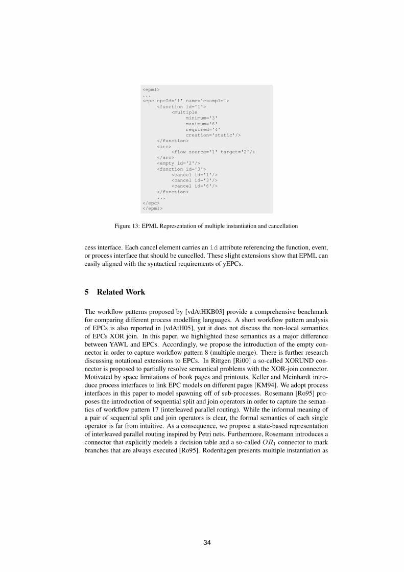
First, the introduction of the empty connector can be easily represented in the EPML
schema. Figure 13 gives the example of an empty connector with an id = 2. The arc
indicates that it follows a function with id = 1. Second, there are dedicated elements
needed for multiple instantiation. Figure 13 gives an illustration of the required EPML
elements. The multiple subelement indicates that the parent function or process inter-
face can be instantiated multiple times. The four attributes capture the semantics of the
parameter described in Section 3.2 and defined in [vdAtH05]. Third, the second function
of Figure 13 shows how multiple cancel elements can be attached to a function or a pro-
33
<epml>
...
<epc epcId='1' name='example'>
<function id='1'>
<multiple
minimum='3'
maximum='6'
required='4'
creation='static'/>
</function>
<arc>
<flow source='1' target='2'/>
</arc>
<empty id='2'/>
<function id='3'>
<cancel id='1'/>
<cancel id='3'/>
<cancel id='6'/>
</function>
...
</epc>
</epml>
Figure 13: EPML Representation of multiple instantiation and cancellation
cess interface. Each cancel element carries an id attribute referencing the function, event,
or process interface that should be cancelled. These slight extensions show that EPML can
easily aligned with the syntactical requirements of yEPCs.
5 Related Work
The workflow patterns proposed by [vdAtHKB03] provide a comprehensive benchmark
for comparing different process modelling languages. A short workflow pattern analysis
of EPCs is also reported in [vdAtH05], yet it does not discuss the non-local semantics
of EPCs XOR join. In this paper, we highlighted these semantics as a major difference
between YAWL and EPCs. Accordingly, we propose the introduction of the empty con-
nector in order to capture workflow pattern 8 (multiple merge). There is further research
discussing notational extensions to EPCs. In Rittgen [Ri00] a so-called XORUND con-
nector is proposed to partially resolve semantical problems with the XOR-join connector.
Motivated by space limitations of book pages and printouts, Keller and Meinhardt intro-
duce process interfaces to link EPC models on different pages [KM94]. We adopt process
interfaces in this paper to model spawning off of sub-processes. Rosemann [Ro95] pro-
poses the introduction of sequential split and join operators in order to capture the seman-
tics of workflow pattern 17 (interleaved parallel routing). While the informal meaning of
a pair of sequential split and join operators is clear, the formal semantics of each single
operator is far from intuitive. As a consequence, we propose a state-based representation
of interleaved parallel routing inspired by Petri nets. Furthermore, Rosemann introduces a
connector that explicitly models a decision table and a so-called OR1 connector to mark
branches that are always executed [Ro95]. Rodenhagen presents multiple instantiation as
34

a missing feature of EPCs [Ro02]. He proposes dedicated begin and end symbols to model
that a branch of a process may be executed multiple times. Yet, this notation does not en-
force that a begin symbol is followed by a matching end symbol. As a consequence, we
adopt the multiple instantiation concept of YAWL that permits multiple instantiation only
for single functions or sub-processes, but not for arbitrary branches of the process model.
6 Conclusion and Future Work
In this paper, we discussed current and potential future workflow pattern support of EPCs.
We have presented three extensions to EPCs. These are in particular the introduction of
the empty connector; the inclusion of a multiple instantiation concept for both simple
functions as well as for hierarchical functions and process interfaces; and the inclusion
of a cancellation concept. We refer to this extended class of EPCs as yEPCs, which is a
tribute to YAWL [vdAtH05]. Furthermore, we have shown that these extensions can be
easily included in EPML. In future research, we aim to define formal semantics for yEPCs
and implement them in a software prototype that uses EPML as an interchange format.
References
[Ar02] Arkin, A.: Business Process Modeling Language (BPML). Specification. BPMI.org.2002.
[CK04] Cuntz, N. und Kindler, E.: On the semantics of EPCs: Efficient calculation and sim-ulation. In: Proceedings of the 3rd GI Workshop on Business Process Managementwith Event-Driven Process Chains (EPK 2004). S. 7–26. 2004.
[GC04] Guabtni, A. und Charoy, F.: Multiple Instantiation in a Dynamic Workflow En-vironment. In: Persson, A. und Stirna, J. (Hrsg.), Advanced Information SystemsEngineering, 16th International Conference, CAiSE 2004. volume 3084 of LectureNotes in Computer Science. S. 175–188. Springer-Verlag. 2004.
[Ki03] Kindler, E.: On the semantics of EPCs: A framework for resolving the viciouscircle (Extended Abstract). In: M. Nuttgens, F. J. Rump (Hrsg.), Proc. of the 2ndGI-Workshop on Business Process Management with Event-Driven Process Chains(EPK 2003), Bamberg, Germany. S. 7–18. 2003.
[Ki04] Kindler, E.: On the semantics of EPCs: Resolving the vicious circle. In: J. Desel andB. Pernici and M. Weske (Hrsg.), Business Process Management, 2nd InternationalConference, BPM 2004. volume 3080 of Lecture Notes in Computer Science. S.82–97. Springer Verlag. 2004.
[KM94] Keller, G. und Meinhardt, S.: SAP R/3 Analyzer. Business process reengineeringbased on the R/3 reference model. SAP AG. 1994.
[KNS92] Keller, G., Nuttgens, M., und Scheer, A. W.: Semantische Prozessmodellierungauf der Grundlage “Ereignisgesteuerter Prozessketten (EPK)”. Technical Report 89.Institut fur Wirtschaftsinformatik Saarbrucken. Saarbrucken, Germany. 1992.
35

[KT98] Keller, G. und Teufel, T.: SAP(R) R/3 Process Oriented Implementation: IterativeProcess Prototyping. Addison-Wesley. 1998.
[MN02] Mendling, J. und Nuttgens, M.: Event-Driven-Process-Chain-Markup-Language(EPML): Anforderungen zur Definition eines XML-Schemas fur EreignisgesteuerteProzessketten (EPK). In: M. Nuttgens and F. J. Rump (Hrsg.), Proc. of the 1stGI-Workshop on Business Process Management with Event-Driven Process Chains(EPK 2002), Trier, Germany. S. 87–93. 2002.
[MN03a] Mendling, J. und Nuttgens, M.: EPC Modelling based on Implicit Arc Types. In:M. Godlevsky and S. W. Liddle and H. C. Mayr (Hrsg.), Proc. of the 2nd Interna-tional Conference on Information Systems Technology and its Applications (ISTA),Kharkiv, Ukraine. volume 30 of Lecture Notes in Informatics. S. 131–142. 2003.
[MN03b] Mendling, J. und Nuttgens, M.: EPC Syntax Validation with XML Schema Lan-guages. In: M. Nuttgens and F. J. Rump (Hrsg.), Proc. of the 2nd GI-Workshopon Business Process Management with Event-Driven Process Chains (EPK 2003),Bamberg, Germany. S. 19–30. 2003.
[MN04] Mendling, J. und Nuttgens, M.: Exchanging EPC Business Process Models withEPML. In: Nuttgens, M. und Mendling, J. (Hrsg.), XML4BPM 2004, Proceed-ings of the 1st GI Workshop XML4BPM – XML Interchange Formats for Busi-ness Process Management at 7th GI Conference Modellierung 2004, Marburg Ger-many. S. 61–80. http://wi.wu-wien.ac.at/˜mendling/XML4BPM/xml4bpm-2004-proceedings-epml.pdf. March 2004.
[MNN04] Mendling, J., Nuttgens, M., und Neumann, G.: A Comparison of XML InterchangeFormats for Business Process Modelling. In: Proceedings of EMISA 2004 - Infor-mation Systems in E-Business and E-Government. LNI. 2004.
[MSN04] Mendling, J., Strembeck, M., und Neumann, G.: Extending BPEL4WS for MultipleInstantiation. In: Dadam, P. und Reichert, M. (Hrsg.), INFORMATIK 2004 - Band 2,Proceedings of the 34th Annual Meeting of German Informatics Society (GI), Work-shop Geschaftsprozessorientierte Architekturen (GPA 2004). volume 51 of LectureNotes in Informatics. S. 524–529. Gesellschaft fur Informatik. 2004.
[NR02] Nuttgens, M. und Rump, F. J.: Syntax und Semantik Ereignisgesteuerter Prozess-ketten (EPK). In: J. Desel and M. Weske (Hrsg.), Promise 2002 - Proceedings of theGI-Workshop, Potsdam, Germany. volume 21 of Lecture Notes in Informatics. S.64–77. 2002.
[Ri00] Rittgen, P.: Quo vadis EPK in ARIS? Ansatze zu syntaktischen Erweiterungen undeiner formalen Semantik. WIRTSCHAFTSINFORMATIK. 42(1):27–35. 2000.
[Ro95] Rosemann, M.: Erstellung und Integration von Prozeßmodellen - Methodenspez-ifische Gestaltungsempfehlungen fur die Informationsmodellierung. PhD thesis.Westfalische Wilhelms-Universitat Munster. 1995.
[Ro02] Rodenhagen, J.: Ereignisgesteuerte Prozessketten - Mulit-Instantiierungsfahigkeitund referentielle Persistenz (Event-Driven Process Chains (EPC) - Multiple Instan-tiation and Referential Persistence - in German). In: Proceedings of the 1st GIWorkshop on Business Process Management with Event-Driven Process Chains. S.95–107. 2002.
[Ru99] Rump, F. J.: Geschaftsprozessmanagement auf der Basis ereignisgesteuerterProzessketten - Formalisierung, Analyse und Ausfuhrung von EPKs. Teubner Verlag.1999.
36

[vdA97] van der Aalst, W. M. P.: Verification of Workflow Nets. In: Azema, P. und Balbo, G.(Hrsg.), Application and Theory of Petri Nets 1997. volume 1248 of Lecture Notesin Computer Science. S. 407–426. Springer Verlag. 1997.
[vdA99] van der Aalst, W. M. P.: Formalization and Verification of Event-driven ProcessChains. Information and Software Technology. 41(10):639–650. 1999.
[vdADK02] van der Aalst, W. M. P., Desel, J., und Kindler, E.: On the semantics of EPCs: Avicious circle. In: M. Nuttgens and F. J. Rump (Hrsg.), Proc. of the 1st GI-Workshopon Business Process Management with Event-Driven Process Chains (EPK 2002),Trier, Germany. S. 71–79. 2002.
[vdAtH05] van der Aalst, W. M. P. und ter Hofstede, A. H. M.: YAWL: Yet Another WorkflowLanguage. Information Systems. 30(4):245–275. 2005.
[vdAtHKB03] van der Aalst, W. M. P., ter Hofstede, A. H. M., Kiepuszewski, B., und Barros, A. P.:Workflow Patterns. Distributed and Parallel Databases. 14(1):5–51. July 2003.
37

38

Model-driven Development of Web Service Transactions
Benjamin A. Schmit, Schahram Dustdar
Vienna University of Technology
Information Systems Institute
Distributed Systems Group
Vienna, Austria, Europe
{benjamin,dustdar}@infosys.tuwien.ac.at
Abstract:Composite Web service design using model-driven approaches has been in use for
several years now, but the modeling of transactional properties is still uncommon andhas not yet been subject to much research. For a distributed system of autonomouscomponents like Web services, especially when they are used for implementing busi-ness processes, transactional guarantees can be of vital importance. In this paper, wepropose a model-driven approach which introduces a separate design layer dedicatedto transactions. We show that our systematic modeling approach is able to introducetransactions in the design without increasing the complexity of the basic UML dia-gram. Our approach can also be reused to specify other properties of Web servicessuch as security requirements or workflows in additional layers.
1 Introduction
Web services have slowly become more and more commonplace over the last years. Lan-
guages like BPEL [BIM�
03] have facilitated the composition of several simple Web ser-
vices into larger composite services. As Web service compositions grow, the complexity
of designing and maintaining business processes increases with them. Tools for method-
ological design like UML [OMG03] have been available for years, and they have also been
applied to business process design [KHK�
03, OYP03, BDS05].
An important property of business processes are transactions. It must be possible to guar-
antee that a business process can have only pre-defined, consistent outcomes (e.g. success
or complete failure, but never a partial result). Transactions can be divided into at least two
types that are relevant for business process modeling [Pap03]: ACID transactions (which
have been used in databases for decades) and long-running transactions which violate
some of the traditional ACID properties. These two main types can be further augmented
with quality of service attributes.
Several specifications exist which augment the basic Web service standards with transac-
tions (e.g. [BIM04b, OAS04, AFI�
03]). The specifications use XML to express trans-
actional semantics. Programmers can combine them with BPEL in order to implement
business processes which depend on the availability of transactions.
39

Implementing transactions directly e.g. according to the WS-BusinessActivity specifica-
tion is error-prone. It is also directly opposed to the model-driven architecture, whose
goal is to minimize the amount of hand-written code by formalizing the design step. On
the other hand, including transactional properties as annotations to the existing design
diagrams might easily make them unreadable, subverting the gains of the model-driven
approach.
In this paper, we propose the use of two layers of design diagrams. The structural layer can
be created with existing model-driven methodologies, and the transactional layer uses a
UML class diagram to model the transactions. These layers are merged by OCL references
from the transactional to the structural view. This approach allows us to easily manage the
added complexity and also helps the architects when design changes are necessary.
In Section 2, we present a case study which we will refer to throughout the paper. Section 3
extracts transactional requirements from the case study and identifies general challenges
with transactions in Web services. As a response to these challenges, Section 4 introduces
our modeling methodology. Structure and transactions of the case study are modeled in
two separate diagrams, and the merge points are identified. Section 5 discusses related
work. Finally, Section 6 sums up the main points of the paper and reaches the conclusion.
It also gives an outlook on future work.
2 Case Study
We will motivate the approach presented in our paper with a case study. Our example is
an extension of similar case studies found in various papers on Web service composition.
The assumptions in this case study contain a few flaws which may not yet be apparent, but
will be revealed during the transaction design phase.
Figure 1 shows how the Web services in our example work together. Web services in
bold font are composite Web services; they require other Web services in order to operate
correctly. The Web services depicted in normal font are typically provided as a company’s
gateway to the outside world. Each of them is managed independently. A UDDI registry
may be used to locate services implementing a given interface, e.g. airlines, but this feature
is not yet included in our case study.
The task of organizing a trip to a conference consists, among other things, of booking
a flight to the conference location, booking a hotel, and organizing the trip between the
airport and the hotel by booking a taxi (for the example, we ignore the possibility of a taxi
stand in front of the airport). The booking services have kindly been provided by umbrella
organizations.
The flight reservation service queries the Web services of some airlines for the availability
of a flight with a given set of restrictions (airports, number of stops, price). Some airlines
access Web services of associated airlines for completing the request (e.g. most Air France
flights within the USA are operated by Delta).
40

FranceAir
AirwaysBritish
Delta Marriott Hilton
Dial−a−CabLondon
Black CabsLondonShuttle
Flight Reservation Taxi Reservation Hotel Reservation
London
Conference Reservation
New York...
Paris...
Figure 1: Case Study: Conference Reservation System
The (fictive) Global Association of Taxi Drivers operates a Web service that offers a sin-
gle access point for the major cities’ taxi associations. As an example, the London Taxi
Driver’s Association’s Web service may query several local taxi companies — other local
associations will likely do the same.
Finally, the hotel reservation service provides uniform access to several hotel chains. Since
most major chains operate globally, a localized service level (as in the taxi reservation
example) is not implemented here.
3 Requirements and Challenges
In this section, we will identify some transactional requirements that can be derived from
the case study. We will also identify some general challenges for Web service transactions.
Not all of the problems indicated here have been addressed in this paper, some are subject
to future work. This list can serve as a guideline for designers of composite Web services.
3.1 Transactional Requirements
In order to implement the collaborative Web services of the case study, the transaction
subsystem (in fact subsystems, since it is unlikely that each company uses the same trans-
action software) needs to fulfill a number of requirements:
41

Long-running Transactions: It is generally accepted (see e.g. [Pap03]) that ACID trans-
actions are unsuitable for most business processes. Traditional database transactions
typically have a short duration, and therefore database tables affected by a transac-
tion can be locked while they are running.
On the other hand, the transactions needed for our case study involve the coopera-
tion of a large number of Web services. Those services do not even belong to the
same company and may be distributed globally. In such a setting, network connec-
tions may fail, subtransactions may need to be compensated, alternative options may
need to be considered, and even human intervention may be necessary. Locking a
database table for the entire time the long-running transaction is active is therefore
no longer practical.
The solution proposed by current Web service transaction specifications like
[BIM04b, OAS04, AFI�
03] consists of weakening the atomicity and isolation prop-
erties so that several concurrent long-running transactions may access the same un-
derlying database tables. They are typically called business transactions, and can
consist of a composition of several ACID transactions.
Alternative Process Paths: In some situations, alternative paths within a business pro-
cess may lead to equally acceptable results. When we want to book a taxi from
Heathrow airport to a downtown London hotel, the goal to have a taxi ready when
we leave the airport (flight delays are not considered here) is more important than
the price difference of a Pound between the available taxi companies.
For the flight selection, on the other hand, the selection of the transaction that will
eventually be committed will usually depend on (preliminary) results returned by
the involved Web services. Air France, for example, does not offer direct flights
from Vienna to London. Booking a non-stop flight with British Airways removes
the inconvenience of switching planes in Paris as well as the possibility of missing
the second flight because of a delay in the first one, and the single flight ticket
may be cheaper than two of them. However, if for some reason we can’t reserve
a British Airways flight, it would still be good to use Air France’s Web service as
a fallback. All of this is known in advance and can be specified explicitly in the
business process.
For the hotel, we have no opinion in advance. We will ask all available hotel chains
and commit the transaction with the lowest price at the specified level of service.
Phased Transactions: As explained in [PC03, LZ04], business transactions could greatly
benefit from a multi-phase model. In this model, a first pre-transaction phase should
establish tentative holds on the resources that will be accessed in the transaction.
In our example, the price of a flight can be queried before the main transaction
phase. If the price should later change or the flight become unavailable, the airline
Web service will notify its client that the tentative hold has been removed, and the
pre-transaction phase needs to be repeated. This procedure reduces the number of
(main) transactions needed in a complex business process and therefore increases
the chance of a successful commit.
42

After the main-transaction phase (which executes the agreement protocol), a post-
transaction phase can be used to exchange materials related to the transaction, e.g. an
electronically signed contract or further details such as when the passengers should
be at the airport and how much baggage they can take with them. These details can
be exchanged after the transaction has committed because they are not important to
the transaction’s outcome, and removing them from the transaction’s body further
reduces the size of the transaction, which in turn reduces the chances for transaction
rollbacks.
Quality of Service: Another issue that needs to be considered is quality of (transaction)
service. We have already discussed the difference between ACID and long-running
transactions, but even these two models can be further subdivided.
Examples of quality of service aspects are whether the transactions can be organized
hierarchically, whether a transaction is local to a single Web service or can be ex-
tended for operation in a composite Web service, whether a transaction is aborted
after some time of inactivity, or whether data regarding the transaction is transmit-
ted via secure channels only. These aspects need to be considered when a composite
Web service is designed.
3.2 Challenges
Because the requirements for Web service transactions differ from those for conventional
ACID transactions, some of the solutions developed for database transactions cannot be
reused and new concepts have to be introduced. We have identified a number of challenges
that need to be addressed:
Transaction Model: For a single Web service, a traditional database transaction may in
some cases be sufficient. However, as soon as Web services are composed to form a
larger composite service, non-ACID transactions are needed so that resources do not
have to be locked for long periods of time [LZ04]. A Web service that uses ACID
transactions per default should be able to distinguish between a simple request to its
ports and a composite request by another Web service.
Compensation: With a non-ACID transactional style, implementing compensation be-
comes a necessity. Many Web services do not provide ports for compensation ac-
tions (such as returning the ticket to the airline with a full refund). If a participant in
a composite Web service transaction decides that the transaction needs to be rolled
back, it must be possible to undo all preliminary results.
Timeouts: The challenge of compensation directly leads to the question of timeouts. A
company needs to be able to specify a maximum time that a transaction can be
running. It would be bad for business if customers could prolong their transactions
and roll back (or compensate) at any time. Airlines, for example, usually charge
different cancellation fees depending on the time remaining until the flight.
43

Transaction Hierarchies: When Web services are assembled to form a composite ser-
vice, it may be helpful to use hierarchical transactions to reflect the structure of the
composite Web service. Within a workflow, hierarchical transactions are also use-
ful because subtransactions can then be exchanged if they fail. In our example, if
the subtransaction involving a given London taxi company fails, we want to create
a second subtransaction with another taxi company. In this case, it is enough if a
single subtransaction commits.
Enforcing Transaction Semantics: Where transaction hierarchies are used, it may hap-
pen that lower-level Web services do not support the transactional properties re-
quired by the higher-level composite services that access them. A transaction needs
to be able to query the properties of subtransactions and report a failure if its features
are insufficient.
Scope of Transactions: In the case of hierarchical transactions, we have to decide whe-
ther we want to use a small number of larger transactions or a large number of
relatively small transactions, i.e. whether the scope of a single transaction should be
large or small. Smaller transactions should reduce the work needed for a potential
compensation in most cases, but they introduce more overhead in transaction pro-
cessing. A problem that has not yet been solved is whether well-sized transaction
scopes can be generated automatically.
Registration: For some Web services, the question when all participants have entered a
transaction can be hard to judge. A stock exchange Web service, for example, may
involve an arbitrary number of interested parties who state their bids in a common
transaction. When the transaction commits, the best bid is selected. However, it
may always be possible that a better bid will arrive after the agreement protocol has
been executed.
Dynamic invocation: When Web services are to be composed dynamically, i.e. at run-
time instead of at build time, an additional difficulty is introduced. The Web service
registry needs to be able to understand differences between transactional models so
that it does not return services that do not fulfill the desired transactional guarantees.
Deadlocks: The distributed nature of Web services adds another difficulty to the problem
of deadlock detection. Different programmers may independently implement a se-
quence of queries to the same Web services, which can interlock during execution.
Detection of such distributed deadlocks is a complicated topic (see e.g. [Elm86]),
especially since short timeouts are not an option for Web services. Again, a good
design methodology can help to discover this problem.
Workflow Issues: In many cases, several equivalent transactions have to be started in
order to compare the offers of different companies. Depending on the preliminary
results (compulsive business offers), a single transaction is committed while the
others are rolled back. Either the transaction subsystem or a workflow engine in
the background must support this typical behavior and allow the specification of an
objective function.
44

3.3 Design Issues
When Web services are built in an ad-hoc way, not all of the above requirements are usually
addressed directly, and not all of the challenges are recognized by the developers. Even
when a design phase precedes the implementation, Web service-specific challenges may
be overlooked.
Therefore, we propose a uniform modeling methodology for Web service transactions
based on UML [OMG03]. Our approach aims at enhancing existing UML diagrams with a
transactional view. The methodology has been developed to support a design that considers
the requirements and challenges of Web services that have been mentioned above.
4 Modeling Transactions
A D
E
C
B
Structural Model
Workflow Model
Security Model
Start End
BusinessActivity
Properties: ...
AtomicTransaction
WS
Transactional Model
Figure 2: The Basic Idea of Our Modeling Methodology
The basic idea behind our modeling approach is a layered design. At the bottom layer we
use the (possibly already existing) UML description of the Web services. Various UML
diagram types can be used for the representation of this basic architecture, as well as other
languages such as BPMN [BPM04], UMM [UN/01], or ISDL [QDvS04].
On top of these diagrams, other diagram layers can be placed. In this paper, we examine
the representation of transactions, but for the future we plan to enhance our modeling
methodology to include at least additional layers for security and workflow management.
Figure 2 depicts the basic idea.
45

As the figure shows, the high-level transactional model references objects in the low-level
structural model. These references are used for establishing transaction boundaries with-
out adding additional complexity to the structural model diagram. The benefits of this
approach will be illustrated towards the end of this section.
For the diagrams themselves, all modeling languages able to express the necessary func-
tionality (composite Web service structure, transactions, security, or workflow) can be
used. Different metamodels can be used for different layers as well. The only additional
requirement is the availability of references to elements of the structural model.
4.1 Extracting Transactions from the Structural Model
start
Start
Success
[success]
okfail fail fail fail
Failure
ok
[success]
ok
[success]
Query next airline
Get offer
Evaluate best offer(user’s criteria)
Choose flight
[airlineId >= airlines]
final
[else] book
next
[else, failure]Book flight
[failure]
fallback
Flight Reservation
Choose service
Service is chosenaccording to city
book
[success]Book taxi
Query next taxicompany
retry
[failure, taxiId < taxis]
Taxi Reservation
Get offer
Choose hotel
According tobest price
Book hotel
final
[hotelId >= hotels]next
[else, failure]
book
[success]
Hotel Reservation
[failure]
fallback
[failure]
[failure][failure, taxiId >= taxis]
[failure]
Reservation
Figure 3: Structure Statechart Diagram
In Figure 3, we have depicted a UML statechart diagram of our case study from Section 2.
This diagram still contains a mixture of Web service structure and workflow issues, which
will have to be divided into two separate layers in the future. Depending on their role in the
collaboration, different participants will be interested in different subparts of this diagram,
which lead to different transactional requirements as shown below:
46

1. The end user of the composite Web service only knows the states Start, Reserva-
tion (“Running”), Success, and Failure. The whole process should therefore either
succeed or fail, and in case of failure any preliminary results should be deleted
(atomicity guarantee). Compensation is not required.
2. The reservation service queries the flight reservation service, the taxi reservation ser-
vice, and the hotel reservation service in sequence (for simplicity, we have chosen
not to use concurrency in this example). Each of those services either fails or suc-
ceeds. In the case of a failure, results from earlier services need to be compensated
to fulfill requirement 1. The flight reservation, however, cannot be compensated —
therefore, its transaction needs to be prolonged until the other transactions commit
successfully.
3. The flight reservation service internally invokes the Web service of each airline in
turn (again we disregard concurrency issues). Then, it compares the offers to find
the one which best suits the user’s requirements. Finally, the flight is booked. As we
have stated in requirement 2, the airlines do not offer compensation. A transaction
with an airline may run as long as 4 hours, then it is terminated by the airline’s
server. Therefore, we wait until the taxi and the hotel are booked until we confirm
the transaction.
4. The taxi reservation service itself only invokes underlying Web services depending
on the desired location, and therefore does not need to fulfill transactional guaran-
tees. The local taxi reservation services, however, provide atomic services since
the servers are geographically close together. Therefore, the local transaction re-
quires the short timeout of 5 minutes. On the other hand, taxi reservations can be
compensated within an hour after booking.
5. The hotel reservation works similar to the airline reservation, except that the hotel
reservation can be canceled. However, according to 2, compensation is not neces-
sary at the higher level. (In a real-world example, we would, after this realization,
rearrange the design of the subtransactions of the reservation service so that the
flight transaction is invoked last.)
4.2 The Transactional Diagram
The structural model diagram already contains much information, and adding transactional
semantics to the diagram would not improve readability. Therefore, we use a separate
UML diagram to capture the transactional requirements identified above.
For the transactional model, we have used a UML class diagram. We did not introduce a
new diagram type because the class diagram is expressive enough for our needs, and exist-
ing UML tools already support this diagram type. Each transaction is modeled as a class.
Subtransactions that are invoked by higher-level transactions are depicted as subclasses.
Finally, tagged values and stereotypes add the necessary transactional semantics.
47

For referencing elements from the structural model, the Object Constraint Language (OCL,
[OMG03]) is used. It is defined as part of the UML specification and is therefore supported
by many UML tools. However, UML can also work with other expression languages if
necessary.
«BusinessActivity»FlightTransaction
{compensation=false,timeout=4h}
airFrance: AirlinebritishAirways: Airlinedelta: Airline
«constructor»
«destructor»Start.start
BookHotel.okChooseFight.fail
«Invocation»TaxiTransaction
{compensation=true,
compensationTimeout=1h}timeout=5m,
london: TaxiAssociationnewYork: TaxiAssociationparis: TaxiAssociation
«constructor»
«destructor»
doLondon«invocation»
doNewYorkdoParis
BookTaxi.okChooseService.fail
BookFlight.ok
«constructor»
«destructor»BookHotel.okChooseFlight.failChooseService.failBookTaxi.failChooseHotel.fail
Start.start
flight: FlightReservation
hotel: HotelReservationtaxi: TaxiReservation
«BusinessActivity»
{compensation=false,timeout=5h}
ReservationTransaction
{compensation=true,
«AtomicTransaction»LondonTaxiTransaction
timeout=5m,compensationTimeout=1h}
londonBlackCabs: TaxidialACab: TaxilondonShuttle: Taxi
«constructor»
«destructor»TaxiTransaction.doLondon
BookTaxi<london>.okBookTaxi<london>.fail
{compensation=truetimeout=1h,compensationTimeout=7d}
HotelTransaction«BusinessActivity»
hilton: Hotelmarriott: Hotel
«constructor»
«destructor»BookHotel.okChooseHotel.fail
BookTaxi.ok
Figure 4: Transaction Class Diagram
Figure 4 shows the transactional model diagram. We have used the terms “atomic transac-
tion” and “business activity” from [BIM04a, BIM04b] to indicate ACID and long-running
transactions. (The transaction specification used by a design diagram, including the agree-
ment protocol exectued, needs to be defined separately to complete the semantics of the
model. In our case, this needs to be done for AtomicTransaction and BusinessActivity.)
They are added to the transaction class as a stereotype. If no transaction needs to be used
for a Web service, the stereotype Invocation is used.
The support for compensating a whole transaction is added to the class as the tagged
boolean value compensation. Similarly, quality of service properties can be specified.
In our diagram, the timeout for the transaction itself and the timeout for invoking a possible
compensating transaction have been included.
The Web services that are coordinated by a transaction are displayed as attributes. The con-
structors of the transaction class indicate the transitions in the structural diagram at which
the transaction must be started. Similarly, destructors show the termination (commit or
rollback) of the transaction. Finally, methods described by the invocation stereotype
can reference the constructors of subtransactions which cannot be mapped to a transition
in the structural model.
48
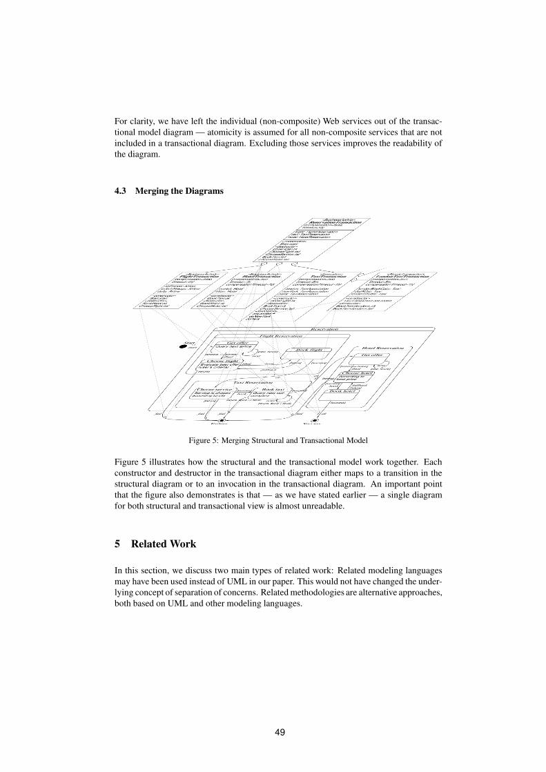
For clarity, we have left the individual (non-composite) Web services out of the transac-
tional model diagram — atomicity is assumed for all non-composite services that are not
included in a transactional diagram. Excluding those services improves the readability of
the diagram.
4.3 Merging the Diagrams
Figure 5: Merging Structural and Transactional Model
Figure 5 illustrates how the structural and the transactional model work together. Each
constructor and destructor in the transactional diagram either maps to a transition in the
structural diagram or to an invocation in the transactional diagram. An important point
that the figure also demonstrates is that — as we have stated earlier — a single diagram
for both structural and transactional view is almost unreadable.
5 Related Work
In this section, we discuss two main types of related work: Related modeling languages
may have been used instead of UML in our paper. This would not have changed the under-
lying concept of separation of concerns. Related methodologies are alternative approaches,
both based on UML and other modeling languages.
49

5.1 Related Modeling Languages
The Business Process Modeling Notation (BPMN) [BPM04] standard describes a notation
for designing business processes. The claim of the document is to unify existing notations,
and to ease design of executable business processes in BPEL4WS [BIM�
03]. Similar
to UML, the specification allows several diagram types. Some transactional properties
(boundaries, compensation) are also supported by the specification. We use the broader
UML specification for our approach because we want to add additional layers like security
to our methodology in the future.
UN/CEFACT’s Modeling Methodology (UMM) [UN/01] is a UML profile for modeling
business processes. Basically, it supports four hierarchically organized views: Business
domains, requirements, transactions, and services. Using these views, a business process
can be modeled top-down. However, graphical modeling of transactional properties is not
mentioned.
The Interaction System Design Language (ISDL) [QDvS04] provides another graphical
language for modeling Web services. We did not use the language in our paper since UML
is more widely known and additionally supports referencing diagram elements with OCL.
5.2 Related Methodologies
[KHK�
03] describes how models from the UML and ADF methodologies can be trans-
formed into platform-specific models. From these models, descriptions in BPEL4WS
[BIM�
03] can be derived. However, transactions are only mentioned as a side aspect
of modeling in the paper. [NK04] extends this approach by defining patterns for the rules.
[OYP03] discusses Web service composition in several phases (definition, scheduling,
construction, and execution). During these phases, the model should gradually become
more concrete. The methodology is based on UML, OCL, and a set of composition rules.
Transactions are not explicitly mentioned in these rules.
[DD04] states that a multi-viewpoint approach is needed for designing composite services.
The paper identifies the viewpoints of interface behavior, provider behavior, choreography,
and orchestration. Petri nets are used for the modeling approach. The paper does not
discuss distributed transactions issues.
[BDS05] also uses statechart diagrams to model composite Web services. The paper
focuses on distributed composition. Transactions are shortly mentioned in future work,
where it states that transactional semantics should be integrated into the model for a group
of states in a statechart. However, no systematic approach is given yet.
50

5.3 Other Related Work
[KB04] proposes a template technique for Web services flows in order to ease service
composition. These templates are parts of a business process description that can be used
for composition. This concept may be useful for transforming our model diagrams into
business process specifications in the future.
[HV03] defines a two-directional mapping between UML activity diagrams and BPEL
process specifications as well as CSP process descriptions. These mappings can be used to
find syntactic and semantic discrepancies in the description. The modeling process itself
is not described. The paper does not explicitly mention transactions.
[Loe04] addresses transactional properties in a distributed middleware setting. The paper
discusses Enterprise JavaBeans, but some of the work can be applied to Web services as
well.
Comprehensive information about Web service transaction specifications can be found in
[Pap03]. An overview on database transaction issues is given by [BGMS92, JK97].
6 Summary, Conclusion and Outlook
In this paper, we have demonstrated the need for a uniform design methodology for Web
services. One layer of this methodology needs to be concerned with transactions. We have
then identified requirements and challenges for Web service transactions for our case study
and in general. Starting from these challenges, we have proposed the use of UML class
diagrams as a transactional layer above a UML statechart diagram describing the service’s
structure.
While modeling the case study, we have identified some problems with our original as-
sumptions, e.g. that the flight should be booked before the hotel and taxi is reserved. In
a real-world example, discovering flawed assumptions would lead to a (possibly iterative)
redesign. A major advantage of the model-driven approach is that conceptual flaws can be
identified before implementation. The proposed introduction of new views can improve
the detection of such flaws.
Throughout the paper, we have emphasized the necessity of separate views (so far, we
have identified structure, transactions, security, and workflow). Figure 5 shows that it is
infeasible to combine all these views into a single diagram, therefore references between
the diagrams are necessary. Whether UML or another modeling language is used is of
secondary importance — we have used UML because it is the de-facto standard for model-
driven architectures.
An interesting result of our work is that most related papers do not discuss transactional
properties of Web services. We think that these properties are an important ingredient for
model-driven Web service design that must not be overlooked.
51

6.1 Future Work
This paper raises a number of questions that have not yet been answered and therefore it
can only be the first part of a larger endeavor. Design requirements for the missing layers
of security and workflow will need to be found, and the necessary semantics will have to
be added to a UML diagram.
The transactional layer itself is also not yet complete. Some requirements have not yet
been included in our model, other challenges still need more research before they can be
supported by a modeling methodology. In the end, the model will have to be formalized,
i.e. the set of stereotypes and tagged values that is used will have to be formally defined.
After this step, it should be possible to automatically derive transactions and transactional
properties from the design diagrams. This automation can be used either to implement
Web services that fulfill certain transactional guarantees, or to check whether existing
services provide the transactional features needed for composition. When the metamodel
is complete, it may well be possible to automate the transition from the UML diagrams to
XML-based process descriptions.
References
[AFI�
03] Arjuna, Fujitsu, IONA, Oracle, and Sun. Web Services Transaction Management, Ver-sion 1.0. Specification, 2003.
[BDS05] Boualem Benatallah, Marlon Dumas, and Quan Z. Sheng. Facilitating the Rapid De-velopment and Scalable Orchestration of Composite Web Services. Distributed andParallel Databases, 17(1):5–37, January 2005.
[BGMS92] Yuri Breitbart, Hector Garcia-Molina, and Avi Silberschatz. Overview of MultidatabaseTransaction Management. VLDB Journal, 1(2):181–239, June 1992.
[BIM�
03] BEA, IBM, Microsoft, SAP, and Siebel. Business Process Execution Language for WebServices, Version 1.1. Specification, May 2003.
[BIM04a] BEA, IBM, and Microsoft. Web Services Atomic Transaction. Specification, November2004.
[BIM04b] BEA, IBM, and Microsoft. Web Services Business Activity Framework. Specification,2004.
[BPM04] BPMI. Business Process Modeling Notation (BPMN), Version 1.0. Specification, May2004.
[DD04] Remco Dijkman and Marlon Dumas. Service-oriented Design: A Multi-viewpoint Ap-proach. International Journal of Cooperative Information Systems, 13(4):337–368, De-cember 2004.
[Elm86] Ahmed K. Elmagarmid. A Survey of Distributed Deadlock Detection Algorithms. SIG-MOD Record, 15(3):37–45, September 1986.
52

[HV03] Reiko Heckel and Hendrik Voigt. Model-Based Development of Executable BusinessProcesses for Web Services. In Lectures on Concurrency and Petri Nets: Advancesin Petri Nets, volume 3098 of Lecture Notes in Computer Science, pages 559–584.Springer-Verlag, September 2003.
[JK97] Sushil Jajodia and Larry Kerschberg, editors. Advanced Transaction Models and Archi-tectures. Kluwer Academic Publishers, June 1997.
[KB04] Dimka Karastoyanova and Alejandro Buchmann. Automating the Development of WebService Compositions Using Templates. In Proceedings of the Workshop “Geschaft-sprozessorientierte Architekturen” at Informatik 2004. Gesellschaft fur Informatik,September 2004.
[KHK�
03] Jana Koehler, Rainer Hauser, Shubir Kapoor, Fred Y. Wu, and Santhosh Kumaran.A Model-Driven Transformation Method. In Proceedings of the Seventh Interna-tional Conference on Enterprise Distributed Object Computing, pages 186–197. IEEE,September 2003.
[Loe04] Sten Loecher. A Common Basis for Analyzing Transaction Service Configurations.In Proceedings of the Software Engineering and Middleware Workshop 2004, LectureNotes in Computer Science. Springer-Verlag, September 2004. To be published.
[LZ04] Benchaphon Limthanmaphon and Yanchung Zhang. Web Service Composition Trans-action Management. In Proceedings of the Fifteenth Australian Database Conference,volume 27 of Conferences in Research and Practice in Information Technology, pages171–179. Australian Computer Society, January 2004.
[NK04] John Novatnack and Jana Koehler. Using Patterns in the Design of Inter-organizationalSystems — An Experience Report. In Proceedings of the OTM Workshops 2004, vol-ume 3292 of Lecture Notes in Computer Science. Springer-Verlag, October 2004.
[OAS04] OASIS. Business Transaction Protocol, Version 1.0.9.1. Specification, 2004.
[OMG03] OMG. Unified Modeling Language Specification Version 1.5, March 2003.
[OYP03] Bart Orriens, Jian Yang, and Mike P. Papazoglou. Model Driven Service Composition.In Proceedings of the First International Conference on Service Oriented Computing,number 2910 in Lecture Notes in Computer Science, pages 75–90. Springer-Verlag,December 2003.
[Pap03] Michael P. Papazoglou. Web Services and Business Transactions. World Wide Web:Internet and Web Information Systems, 6(1):49–91, March 2003.
[PC03] Jonghun Park and Ki-Seok Choi. Design of an Efficient Tentative Hold Protocol forAutomated Coordination of Multi-Business Transactions. In Proceedings of the IEEEInternational Conference on E-Commerce, pages 215–222, June 2003.
[QDvS04] Dick Quartel, Remco Dijkman, and Marten van Sinderen. Methodological Supportfor Service-oriented Design with ISDL. In Proceedings of the Second InternationalConference on Service Oriented Computing. ACM, November 2004.
[UN/01] UN/CEFACT. UN/CEFACT’s Modelling Methodology, Version 10. Specification,November 2001.
53

54

XML based Process Management in Cryo-Biotechnology:
The ChameleonLab
Christopher H.P. Durst(1), Frank R. Ihmig(1), Matthias Biel(2), Martin Daffertshofer(2) and
Heiko Zimmermann(1)*
(1) Abteilung Kryobiophysik & Kryotechnologie
Fraunhofer-Institut für biomedizinische Technik (IBMT)
Ensheimer Straße 48
66386 St. Ingbert, Germany
(2) Evotec Technologies GmbH
Schnackenburgallee 114
22525 Hamburg, Germany
Abstract: In this paper, we introduce a completely new kind of lab management
system, ChameleonLab. We present the main ideas, areas of application, of an
XML-based implementation of ChameleonLab and a production system in a large-
scale cryobank. The main feature of ChameleonLab is its ability to handle new and
future proof substrates for cryobanking. These consist of miniaturised multi-wells
and unique cryo-tolerant memory-chips. XML-files stored on memory-chips
attached to the samples allow complete control of preparation and handling
laboratories. Additionally, full documentation relevant to clinical application is
stored decentralised in XML-files on the sample-attached memory-chip. We show
the unique feature of ChameleonLab is to schedule and control both automated and
manual operating steps. This allows scaling from the small lab to high-throughput
environments. Device concepts of implementation like generic and human devices
are exemplified. We show that management of biotechnological labs is a new and
relevant application area for XML.
1 Introduction
The widespread progress in biomedical science requires new techniques and new
technologies for coping with new cell uses. Live cells need to be stored for decades for
later stem cell therapy, retrospective diagnostics or tissue engineering [KBRAGW04].
Future biomedical science is certain to create many new applications. Diverse medical
applications require different cell workflows. A cell workflow consists of both cell
treatment steps and cell handling steps. Treatment is defined to be anything that causes
an effect on the cell, whereas handling denotes any activity that does not. In the future,
biomedical laboratories will need to carry out a large number of different workflows
including steps for cell storage.
55

Already today’s biomedical labs need to have a more flexible and dynamic workflow
management than conventionally established. Different solutions are explored in
[MY04] and [FK04]. The facts mentioned below show the need for further improvement.
Large numbers of cell samples need to be stored now for later use. Estimates range to
more than a billion samples in the next few years.
There is currently only one practical long-term storage technique available for living
cells: cryopreservation. It is based on freezing cells and storing them at temperatures
between –130°C and –196°C. Liquid nitrogen maintains these temperatures. This
technique is well established but the old technology is no longer suitable such high
sample numbers. Therefore, the Fraunhofer-Institute for Biomedical Engineering
(IBMT) is reengineering the technology and improving the cryopreservation techniques
and evolving the future standards [ZKIDSF04].
The main differences between the new IBMT technology and the old one are a dramatic
reduction of sample size to between 1/50 and 1/2000 of conventional volumes and the
physical attachment of a cryo-tolerant memory chip to each sample carrier or stack. This
is now possible because of progress in low temperature electronics [ISZ03], [ISZ04] and
[ZIS04]. Each sample’s data is stored at-sample on-chip to avoid possibly lethal
mistakes in data and sample association, especially in situations of sample exchange.
The sample always carries its own information. The need for this solution can be seen in
detail in [DIHZ04]. Already in the past, there have been efforts for improving structure
and management of biological data [RR04] and [YBM04] showing the insufficiency of
conventional sample data handling.
Fig. 1: Comparison of conventional cryotechnology and Fraunhofer IBMT’s reengineered
cryotechnology. More information can be found in the text.
56

Whereas a cell‘s volume is 1 pl on average, the smallest conventional cryotubes on the
market have a volume of 1 ml. For coping with future cell sample numbers,
miniaturization of volume is required and biologically useful. IBMT’s miniaturized
substrate contains 30 sample wells of 25 µl volume in a plate of 4x3 cm. Furthermore, in
conventional sample storage, sample data are stored in a database to which is referred by
a sample identification label, e.g. a barcode. In contrast to that, there is a low
temperature tolerant memory chip attached to each single miniaturized substrate or stack
with a capacity of up to 1 GB. All sample data are stored at-sample on-chip in an XML
file.
The at-sample on-chip data can be backed up in an adaptive sample database for
cryobanking [Du03]. Currently, an XML file is used for the on-chip data.
The idea for ChameleonLab has been born from the following facts:
- Lab workflow definitions depend on cell type and on the future purpose of a
cell sample. Individual workflow definitions must be allowed for special
purposes.
- There will be sample exchange between different labs and cryobanks, e.g. when
a cryopreserved cell sample is needed for a therapeutic purpose. This requires
exchange of the workflow definitions associated to a sample. Therefore,
workflow definitions must be independent of any particular lab. Labs must be
able to treat and handle cells purely according to the workflow definitions.
- Mistaking of workflow definitions carries the same risk as errors in sample
data.
- Workflow documentation is important. Depending on cell type and biomedical
purpose, there are different duties by law for documentation. Cell samples for
therapy are defined to be medicines for which e.g. the German medicine act
obliges them to be documented in detail for up to 15 years, including each
workflow step. Exchange of workflow documentation is important to labs,
physicians and science.
2 The ChameleonLab principles
In order to cope with the facts mentioned above, ChameleonLab is based on the
following principles.
1) The workflows associated to a sample are defined at-sample.
57

2) Instead of being a reference to an existing workflow definition, the sample-chip
combination is the workflow definition. That means that each single treatment
and handling step is defined in detail at-sample on-chip. Thus, labs using
ChameleonLab are able to perform workflows unknown before arriving of the
sample. The workflow definition is transported in a form suitable for direct
apparatus control. Therefore, the sample dictates the lab behaviour spanning the
lab type from completely manual to fully automated.
3) Workflow documentation data is stored at-sample.
Fig . 2: Schematic view of the ChameleonLab principles showing a sample-chip combination
and a cell sample to which the workflow definition is associated.
The at-sample on-chip workflow definition dictates the lab’s behaviour. Before
execution starts, the lab is configured and initialised accordingly to the workflow
definition. Therefore, the lab is transferred from an idle state ‘LABOR’ to the defined
state ‘LABOR*’. In this state, the workflow is done. The cell sample changes by
workflow. Workflow documentation data is stored at-sample on-chip. After finishing
workflow, the lab returns to idle state ‘LABOR’.
3 An implementation of ChameleonLab
For a working implementation of the ChameleonLab and a proof-of-concept, we have
decided to develop an existing workflow management system to ChameleonLab
functionality. Firstly, the at-sample workflow definition and at-sample workflow
documentation functions need to be realised. This can be done easily by extending the
on-chip XML file by workflow definition tags and workflow documentation tags.
58

‘Bernstein’ is a well-known workflow management software in the biotechnology
market [GB00] controlling fully automated high throughput screening machines for
pharmaceutical products. These machines are called HTS modules and consist of
different automatic devices like pipette arrays, incubators, screeners, and robotic
handling mechanisms for micro-titer plates. In an HTS module, a large number of
samples is transported automatically between the different devices carrying out the
operational steps defined for a pharmaceutical screening workflow.
The interaction of the different devices within such an HTS module is supervised by
Bernstein. Bernstein is a dynamic scheduler suited and adaptable for all screening
workflows that can be described as a sequence of operating steps. The operating steps of
any screening workflow need to be allocated to the different devices of the HTS module
capable of the appropriate step requirements. A Bernstein process is defined to be a
subsequence of operating steps which can be fulfilled in direct succession at a particular
device. Thus, any screening workflow is a sequence of several Bernstein processes being
executed by the appropriately allocated devices.
Each single device is controlled by individual device software. The Bernstein scheduler
controls the interaction between the different devices by communicating with each
device’s software.
But how can Bernstein be used for development of Chameleon Lab? First of all, any cell
workflow is in fact a sequence of operating steps, namely of cell treatment steps and cell
handling steps as can be seen by analysing biomedical protocols. Thus far, Bernstein’s
functionality matches any biomedical workflow definition well. In an HTS module,
Bernstein schedules the operating steps by scheduling those devices to which the
operating steps are allocated. This principle implies that all operating steps of any
biomedical workflow have to be allocated to appropriate devices in a biomedical lab for
being scheduled by Bernstein. Moreover, each lab device needs to be controlled by its
own device software for communication with Bernstein. In fact, transferring the function
of Bernstein to a biomedical lab regards the biomedical lab as a distributed HTS module.
This is the key for our further development.
But in state-of-the-art biomedical labs many of the cell treatment and cell handling steps
of a workflow cannot be allocated to devices. This is because there are many simple
manual operating steps. Having all of them fulfilled by machines would be a loss of
efficiency, require many expensive devices more and would not be cost-effective.
Additionally, there are many small and simple devices that do neither have software nor
computer interface and therefore need to be operated manually.
Furthermore, there are also many devices controlled by their own software but having no
interface to Bernstein. A standard lab apparatus interface and protocol do not exist so far.
Thus, scheduling of manual operating steps must be enabled. This requires the allocation
of manual operating steps to an appropriate device.
59

An appropriate device for manual operating steps is the human device, e.g. a lab
employee. To schedule a human device’s operating steps we need a communication
interface. Therefore, we have developed the so-called ‘generic device’ software.
Basically, the generic device software has the same functionality as any other device
software in an HTS module. There is initialisation by Bernstein and communication with
both Bernstein and the device itself. But there is one main difference arising from the
abilities of a human device: the ‘generic device’ software is compatible with all manual
operating steps. That means that a single software device can cope with the large number
and variety of manual operating steps in a biomedical lab. As with any other device
software, the ‘generic device’ software can control the execution of a sequence of
different operating steps. The user interface consists of instructions to the human device
in HTML format and of input forms for feedback; this is necessary to get the
documentation data for manual operating steps.
Using the human device and the ‘generic device’ software, any manual operating step
can be allocated. Thus, Bernstein can now schedule all operating steps of any cell sample
workflow in a biomedical lab that can be regarded as distributed HTS module consisting
of different technological devices and the human device.
With this solution, any biomedical lab can be turned into a ChameleonLab simply by
using one human device and installing one instance of the ‘generic device’software. Also
those biomedical labs without any Bernstein compatible technological devices can be
turned into ChameleonLabs by having the devices operated manually using the human
device and the ‘generic device’ software.
This solution is fully scalable for any size of lab facility. There can be several human
devices in a biomedical lab and several instances of the ‘generic device’ software, e.g.
one in each lab department for achieving higher sample throughput.
We have added XML functionality to both the Bernstein scheduler and the ‘generic
device’ software. Now, Bernstein can read the at-sample on-chip XML file and access
the workflow definition for fully automatic initialisation of the ChameleonLab. The
‘generic device’ software is able to write documentation data into the on-chip XML file
while an operating step is being executed. Bernstein, the technological devices and the
instances of ‘generic device’ are equipped with a chip reader for accessing the on-chip
XML file.
60

Fig. 3: Visualization of a schematic workflow for L929 fibroblast cells in the ChameleonLab. For
further details see text.
61

Figure 3 shows on the right side the initialisation of ChameleonLab which is done by
inserting the at-sample chip into Bernstein’s chip reader. The on-chip XML workflow
definition is loaded and initialises the lab’s devices allocated to the operating steps.
During workflow execution, Bernstein controls the interaction of the devices and
schedules the processes and operating steps. The chip escorts the sample to each device.
Therefore, each device is equipped with a chip reader for supplying the on-chip XML
file for writing documentation data into by each device’s software. On the left side, some
operating steps of the workflow are illustrated from top to bottom. The two uppermost
operating steps are fully manual steps which must be fulfilled by the human device.
Therefore, both operating steps need to be scheduled by an instance of the ‘generic
device’ software forming the interface between Bernstein and the human device. Taking
place in the same department of the lab, the same human device and the same instance of
‘generic device’ is used for both operating steps. The generic device presents HTML
sheets instructing the human device and supplies input forms for documentation data
input. The next process is allocated to the nanoplotter, a fully automated device for
pipetting small volumes of cryoprotecting solution. This device is controlled directly by
Bernstein using a fully compatible device software. The next operating step is a semi-
manual sample freezing step. The allocated device is a freezer with non-compatible
device software and, therefore, has to be operated manually. Here, the human device is
scheduled by the ‘generic device’ instance of the lab’s freezing department. The last
operating step is again manual and to be done by the human device as described above.
The black border around Bernstein’s topography is defined to show the grade of a
device’s integration. A fully compatible device can communicate directly with Bernstein
through a compatible device software and can be scheduled directly. This is indicated by
the black border enclosing the device. Human devices or semi-manual devices are not
enclosed by the black border because they need scheduling by an instance of the ‘generic
device’ software. Looking at the Bernstein topography marked by the black border, one
can see that this topography changes accordingly to the devices allocated to processes.
That means that the Bernstein topography adapts to the sample workflow definitions.
4 ChameleonLab as a production system
ChameleonLab is established in the first large-scale research and demonstration
cryobank EurocryoSAAR since Autumn 2003 (www.eurocryo.de). EurocryoSAAR
currently has 22,000 liters of cooled volume and an infrastructure allowing a maximum
of 220,000 liters of nitrogen-cooled storage volume. All cryo preparation labs are
controlled and adapted by the stable version of ChameleonLab using XML at-sample on-
chip files. In EurocryoSAAR, ChameleonLab is connected and synchronized to a web-
based sample database capable of workflow definition and memory chip initialisation.
62

Fig. 4: The EurocryoSAAR large-scale cryobank.
Cell samples are stored long term in the cryotanks using Fraunhofer IBMT’s
miniaturized substrates with a memory chip attached. Each sample has been prepared in
labs equipped with the ChameleonLab implementation. In a tank with capacity of 1400
liters, 15000 microwell plates with attached chips can be stored.
References
[KBRAGW04] Kruse, C.; Birth, M.; Rohwedel, J.; Assmuth, K.; Goepel, A.;Wedel, T.:
Pluripotency od adult stem cells derived from human and rat pancreas. Applied Physics A, (2004),
Published Online:26 May 2004, Springer-Verlag.
[DIHZ04] Durst, C. H. P.; Ihmig, F. R.; Hotz, G.; Zimmermann, H.: The demand for low
temperature electronics in cell cryobank databases. Proc. 6th European Workshop on Low
Temperature Electronics, WOLTE-6, ESTEC, Noordwijk, The Netherlands, 2004; pp. 279-286.
[ISZ03] Ihmig, F. R.; Shirley, S. G.; Zimmermann, H.: Evaluation and Adaption of Flash-
Memory for Cryobiophysical Applications. Proc. 2nd VDE World Microtechnologies Congress, pp.
643-648, Munich, 2003.
[ISZ04] Ihmig, F. R.; Shirley, S. G.; Zimmermann, H.: Electronic Memory Devices for
Cryobiological Applications. Proc. 6th European Workshop on Low Temperature Electronics,
WOLTE-6, ESTEC, Noordwijk, The Netherlands, 2004; pp. 153-160.
[Du03] Durst, C. H. P.: Analyse der Anforderungen an Datenbanken für die Langzeitablage
biologischer Zellen. Diplomarbeit, Universität des Saarlandes, 2003.
[ZIS04] Zimmermann, H.; Ihmig, F.R.; Shirley, S.G.: A low cost stage for testing electronics
between room and liquid nitrogen temperatures. Proc. 6th European Workshop on Low
Temperature Electronics -WOLTE-6, ESTEC, Noordwijk, The Netherlands, 2004; S.287-293.
[ZKIDSF04] Zimmermann, H.; Katsen, A. D.; Ihmig, F. R.; Durst, C. H. P.; Shirley, S. G.; Fuhr,
G. R.: First Steps of an interdisciplinary approach towards miniaturised cryopreservation for
cellular nanobiotechnology. IEE Proc.-Nanobiotechnol., Vol. 151, No. 4, August 2004; pp. 134-
138.
63

[GB00] Gentsch, J.; Bruttger, O.: High Throughput Screening at the Nano Scale. Journal of the
Association for Laboratory Automation (JALA), Volume 5, Issue 3, pp. 60-65, 1 July 2000.
[YBM04] Yang, S.; Bhowmick, S. S. ; Madria, S.: Bio2X: a rule-based approach for semi-
automatic transformation of semi-structured biological data to XML. Data & Knowledge
Engineering, published online: 1 July, 2004.
[RR04] Russo, M.F.; Rubin, A. E.: An Introduction to Using XML for the Management of
Laboratory Data. Journal of the Association for Laboratory Automation, Volume 6, Issue 6, 1
December 2001, pp. 89-94.
[MY04] McIntosh, R. L.; Yau, A.: A Flexible and Robust Peer-To-Peer Architecture with XML-
Based Open Communication for Laboratory Automation. Journal of the Association for
Laboratory Automation, Volume 8, Issue 1, 1 February 2003, pp. 38-45.
[FK04] Fakas, G. J.; Karakostas, B.: A peer to peer (P2P) architecture for dynamic workflow
management. Information and Software technology, Volume 46, Issue 6, 1 May 2004, pp. 423-
431.
64

Improving Workflow Project Quality Via Business Process
Patterns Based on Organizational Structure Aspects
Lucinéia Heloisa Thom1,2, Cirano Iochpe1, Bernhard Mitschang2
1Institute of Informatics Federal University of Rio Grande do Sul
Av. Bento Gonçalves 9500 90610 Porto Alegre, Brazil
[email protected] [email protected]
2Institute for Parallel and Distributed Systems University of Stuttgart Universitätstrasse 38
70569 Stuttgart, Germany [email protected]
Abstract: The correct definition of business process is a key to achieve quality in workflow project. Accordingly, this paper proposes business (sub)process candidate patterns to be used in business process modelling. The candidate patterns differ from other proposals first because they focus on task flow descriptions and second because they are based on organizational structural aspects. Our proposal is to store the patterns in the catalogue of the Transactional Metamodel of Business Process introduced in this paper. The metamodel makes feasible the modelling of business process through the use of business subprocess patterns based on organizational structural aspects. An additionally feature of the metamodel supports the generation of business subprocess patterns through the Business Process Execution Language for Web Services (BPEL4WS).
1 Introduction
Organizations reach their business objectives by executing their business process. A business process can be understood as a partial order of tasks, where each tasks contributes in a stage of the process. In this context a business subprocess is a process integrated to as well as controlled by another business process.
Business process has an important role in how organizations are structured. Mostly researchers and professionals agree that first the business process must be defined and after this the organization must be shaped to best operate it [DW96]. Accordingly, to shape an organization involves at least two steps. In the first step business processes executed in the organization are identified. In the second step, concerning the business processes, specific values are assigned to a set of structural aspects1.
1 Structural aspects are per example the centralization of decision-making, the coordinate mechanisms and the scalar chain. The set of structural aspects differs one kind of organization to another (e.g., matrix, functional and linear).

Modern organizations have performance demands related at least to both the execution time and resource consumption of their business process. Within this context, the workflow technology has shown to be very effective, mainly in business process automation.
A business process model offers domain level concepts and enables a broader distribution of knowledge among other business-related people with different skills and knowledge of an organization [Ju03]. A business process is automated through a workflow process. Based on a workflow metamodel a workflow process groups all elements required for the business process automation. These elements comprise not only dynamic aspects (tasks and transitions) but also static aspects (data, application and participants). Hence, a workflow process model can contain aspects not represented in the corresponding business process model [Fr04].
This paper proposes a new approach for business process modelling. The key concept of the approach is business process candidate patterns based on organizational structure aspects. Each pattern characterizes a relation between one or more organizational structure aspects of an organization and corresponding business process executed on it. Per example, the structure of a document approval process may vary depending on the level of centralization of decision-making (less or more) in high positions (e.g. manager, president) of the organization. The use of this class of patterns in business process modelling may improve the workflow project accuracy hence the workflow process will better represents the real business process as it is executed in the organization.
In the remainder of Section 1 we address the problem that motivates our research as well as corresponding proposal to solve the problem. Furthermore, we survey related work. Section 2 describes the Governmental Organization where the business subprocess candidate patterns, proposed in this paper, were discovered. In section 3 examples of candidate patterns are presented. Section 4 describes a Transactional Metamodel of Business Process (TMBP). In Section 5 we propose a methodology describing how TMBP can be used in business (sub)process modelling. Finally, section 6 gives an outlook to future developments and research directions.
1.1 Problem Statement
Recently, Business Process Modelling and Workflow Process Modelling became subject of various specifications and standardization efforts [MSN04]. Different consortia including the Business Process Management Initiative (BPMI) as well as the Workflow Management Coalition (WfMC), the World Wide Web Consortium (W3C) and the Organization for the Advancement of Structured Information Standards (OASIS) have proposed metamodels for business process modelling and workflow process modelling. However, these metamodels present some limitations:
their submodels for organizational structure aspects representation show limited power of expression. Most of them just consider the use of organizational structure aspects in the assignment of task execution performer.
66

the use of business process patterns based on organizational structure aspects is not considered in business process modelling. Accordingly, the reuse advantages of patterns are not applied in the workflow project modelling phase. Therefore not only performance but also quality of whole workflow project may not be guaranteed. Nevertheless, the workflow process may not represent the real business process as it is executed in the organization, hence the organizational structure aspects are limited related with business process modelling.
1.2 The Proposal
This paper proposes:
Candidate patterns for business (sub)process modelling based on organizational structure aspects2. We call candidate pattern because we agree with the pattern community consensus that a pattern can be established after it is identified in at least 3 real cases. Our approach considers only one workflow application, although this application was implemented through a (large) set of workflow process. Accordingly, we need two more workflow applications to prove our candidate patterns. Nevertheless, we understand a business (sub)process pattern as a set (one or more) of recurring tasks that can be reused in specific situations concerning related organizational structure aspects. We are looking forward to store the patterns in the patterns catalogue of TMBP.
Aiming implementation issues we also propose TMBP methodology. The methodology comprises tree steps: (1) creation of business process models through TMBP; (2) automatic generation of BPEL4WS3 processes corresponding to the business process models and; (3) execution of BPEL4WS process via workflow engine.
We opted for BPEL4WS in favor of other languages (e.g., the Business Process Modelling Language (BPML) [Ar02] and the Web Service Flow Language (WSFL 1.0), first because of the reuse properties of BPEL4WS and second because of the existence of powerful development of tools and other technologies that greatly increase the level of automation and thereby lower the cost in establishing cross-enterprise automated business process. Moreover, BPEL4WS advantages are recognized by UML community, providing, mappings from UML to BPEL4WS [Ga03], [LR04].
2 We developed a case study where we identified dependency relationships between one or more organizational structure aspects and its more than 60 workflows sub-processes. Each relationship gave rise for a candidate of business (sub)process pattern. [TI03] 3 Business Process Execution Language for Web Services.
67

1.3 Related Works
Patterns capture existing, well-proven experience in software development and help to promote good design practice [BUS96]. However, patterns for business process and workflow process modelling are still subject of discussion and research. This section reviews some of existent work in this context.
Wil van der Aalst proposed 21 workflow patterns for the description of business process behaviour [Aa00], [Aa03]. Each pattern represents a routing construction (e.g., sequential, parallel and conditional) to be used in workflow process modelling. More recently, the author proposed a set of workflow data patterns aiming to capture the various ways in which data is represented and utilized in workflows [SHE04]. However, patterns are connected with organizational structure aspects.
Workflow patterns were also proposed in the context of WIDE4 project. WIDE approach for modelling phase of a workflow system is mainly based on the use of a pattern catalogue, which can be reused in several projects [GPS03]. The patterns proposal of WIDE is also not based on organizational structure aspects.
Last but not least, SAP5 created a cross-application tool called SAP Business Workflow. The tool makes feasible the integration of business tasks between applications [An03]. It also includes a workflow wizard with workflow templates (e.g., approval procedures) [SPH03]. However, these templates are only slightly linked with organizational aspects.
2 Governmental Organization Profile
This section provides an overview of the governmental organization used as scenario to discover the candidate patterns proposed in this paper. The main activities accomplished in the organization refer to the Environmental Licensing Process6. Follow sections present core organizational structure aspects of the governmental organization.
2.1 Scalar Chain
The scalar chain specifies who is subordinated to whom in organizations [Ch00]. It is defined based on the organizational chart7. Accordingly, the governmental organization scalar chain is defined through four positions8: the president, the director, the division manager and the department manager (as shown in Figure 1).
4 Workflow on Intelligent Distributed database Environment Model. 5 Anwendungen und Produkte in der Datenverarbeitung in der Datenverarbeitung. 6 The environmental licensing process involves administrative tasks such as preparation and approval of official documents, inherent to the issue of a certain environmental license. 7 The organizational chart describes the organizational structure by its organizational units (e.g., departments, divisions and staffs) and their respective relationships [Ju04] 8 A position is an elementary description of the responsibilities of an employee [Ju04].
68

organisational chartscalar chain
Presidency
Staff
Technical Direction Administrative Direction
Division of
Environment
Licensing
Control
Division
Department Manager
Division Manager
Director
President
Administrative
Department
Financial
Department
PresidencyPresidency
StaffStaff
Technical Direction Administrative DirectionAdministrative Direction
Division of
Environment
Licensing
Control
Division
Control
Division
Department ManagerDepartment Manager
Division ManagerDivision Manager
DirectorDirector
PresidentPresident
Administrative
Department
Financial
Department
Financial
Department
Figure 1 – Scalar chain and organizational chart of the governmental organization
2.2 Decision-Making Structure
Authority to decision-making in organizations can be less or more centralized. In thefirst case, individuals at the top of the organizational chart has the highest authority tomake decisions and authority of other individuals is delegated, top-down, according totheir position in the organizational chart [JON01]. In the governmental organizationauthority to decision-making is high centralized in positions at the top of itsorganizational chart.
2.3 Coordination Mechanisms
In our approach to coordinate means to manage dependencies between tasks andbetween requirements needed for task execution. Coordination mechanisms can be classified in mutual adjustment, direct supervision, standardization of work processes,standardization of results and standardization of skills [Mi95]. In the governmentalorganization we identified not only direct supervision9 but also standardization ofskills10.
3 Candidate Patterns for Business (Sub)process Modelling
Due to space limitation the technique used to identify the business process candidatepatterns is not described in this paper. Information about it is in [TI03]. Through thetechnique, at about 5 candidate patterns were identified. The candidate patterns can beconsidered complementary, hence they should be extended as Subsection 4.5 proposes.Next Subsections bring two examples of candidate patterns described throughBuschmann notation [Bu96] and illustrated via activity with actions diagram of UML 2.0[Om03]. Figures 3 and 4 must be, respectively interpreted according with Legend Figure2 brings.
9 A position coordinates the work executed by another positions (subordinate), guiding and monitoring them.10 Predefined abilities (e.g., know how to program in Java) the task performer needs to have.
69

3.1 Candidate Pattern for Question Answering
The question answering process concerns the identification of specific skills needed for a task execution performer. Depending on the skills a particular organizational role andcorresponding actor is assigned for both task execution and question answer.
Name: Question Answering
Context: During a task execution, questions concerning its execution can emerge.Hence, is desirable to have task performers with appropriate skills and knowledge to execute it. Accordingly, the question answer pattern includes two parameters: a task anda question.
Problem: Questions can emerge during the execution of a specific task.
Solution: the question answering candidate pattern is recommend in these bothsituations: (1) a question answering process needs to be modelled; (2) specific skills are required for the task performer. Figure 3 illustrates the candidate pattern.
Figure 2: Legend
ToIdentifySkills
ToIdentifyOrganizationalRole ToSelectActor
ToAnswerQuestion
QuestionTask
Figure 3: Candidate patterns for questionanswering
As shown in Figure 3, not only desirable skills needed for task execution are identifiedbut also corresponding organizational role. Based on the organizational role the bestactor is assigned for task execution.
3.2 Candidate Pattern for Document Approval
The document approval process is a sequence of agreements. Each agreement is performed by one organizational role. The process ends when all organizational rolesconclude their evaluations or one of then does not agree with the document content.
Name: Document Approval
Context: In this paper to approve means to make a decision about something that needsto be evaluated. Accordingly, the approval process includes at least two parameters: anitem (e.g., document) and an organizational role responsible for decision task.
Problem: The structure of the document approval process may vary depending on thelevel of decision-making i.e., less or more centralized.
Solution: The document approval candidate pattern is recommend when these twosituations are identified: (1) an approval process must be modelled and; (2) the process isexecuted in a context with high centralization of decision-making and direct supervisionof work. Figure 4 illustrates the candidate pattern.
70

Approval
ToReviseItem
approve disapprove
Item
ToRecordSignature ToAnnulPreviousSignature
OrganizationalRole
Figure 4: Candidate Pattern for Document Approval
In Figure 4 an organizational role performs a document review (item). In case it agreeswith the document content its signature (proving his approval) is recorded. In case it disagrees, all previous signatures (in case they exist) are annulled and the process shouldend. The actions inside the dashed line are repeated in the number of organizational rolesgiven by input parameter or some disapproval occurs.
4 Introduction to TMBP
TMBP is an extension of the Transactional Model of Workflow Processes developed inthe context of WIDE project. Nevertheless, the metamodel is a package composed of
five subpackages (see Figure 5). While PBusinessProcess package depends on the
POrganizational, PResource and PRouting packages, PCatalogue
package depends on POrganizational and PBusinesProcess packages.
The metamodel is described through Unified Modelling Language (UML) notation[FS00]. We opted for UML because it provides a wide range of modelling resources,such as class diagram, use case diagram and activities with actions diagram required torepresent all TMBP singularities.
Transactional Metamodel of Business Process (TMBP)
PBusinessProcess
PCatalogue
POrganizational PResource
PRouting
Figure 5: Transactional metamodel of business process
71

4.1 Organizational Package
Roles (as shown Figure 6) can be differentiated between functional11 and organizationalroles12 [NS02]. An organizational role is associated with actor13 and with organizationalunit (e.g., department, division). Nevertheless, it is a generalization of functional role. Afunctional role is associated with skill (e.g., to know how to program in Java) andcompetence (e.g., may sign orders > than $ 20.000 ).
An organization is an aggregate of organizational units. Each organizational unit may be related with other organizational units. The relationship not only helps in organizationalchart definition but also expresses multi-dimensional organizations (e.g., matrix-structures) [Mü99].
Competence Functional
0..*0..* 0..*0..*
Skill0..* 0..*0..* 0..* StructuralAspect
Organization
SetOfStructuralAspects 0..* 1..*0..* 1..*
OrganizationalUnit
0..*
1
0..*
1
Actor
OrganizationalRole
0..*0..* 0..*0..*
0..*
0..*
0..*
0..*
0..*
0..*
0..*
subordinated of
0..*
Figure 6 – Organizational package
4.2 Routing Package
Routing along particular branches determines which task needs to be performed and inwhich order [AH02]. We apply Wil van der Aalst workflow patterns in TMBP routingpackage [Aa00] (see Figure 7). Due to space limitation we present a simplified class diagram just to illustrate the routing patterns we are considering. A detailed explanationbased on the solution of [Wh04] can be found in [Th04].
Routing
msg
Sequence
ParallelSplit
Syncronization
ExclusiveC
Choice
condition
Discriminator
MultipleC
···
Figure 7: Routing package
11 E.g., to formulate rules; to review and approve documents.12 E.g., manager, director, president.13 An actor is the responsible for a task execution.
72

4.3 Resource Package
A resource defines artifacts needed for the execution of a task [Ju03]. The Resourcepackage (as show Figure 8) distinguishes two kinds of resources: a tool (e.g., word
processor, printer) and an item instance of ItemType (e.g., official document, chair’s
back). Depending on the kind of item, it may have a structure (class
ProductStructure in Figure 8).
Resource
Tool ProductStructureItemType0..10..* 0..10..*
Figure 8 – Resource package
4.4 Business Process Package
In business process package (see Figure 9) each business process transforms an itemtype (as resource package defines) from an initial state into a final state. Transformationsmay be decomposed in smaller transformations, where each of them corresponds to achange in the item state. When there are no more transformations to be performed, theitem reaches its final state and the organization reaches the aim of its business.
Each business subprocess can involve several business transactions, also several actors.However, the set of organizational structure aspects and their values should remainconstant in the business subprocess. A business subprocess can involve one or moreorganizational units if their organizational structure aspects do not vary. Additionally,each business subprocess has only one responsible.
A business process can be recursively decomposed in business subprocess, up to the business transaction level. A business transaction is the smallest business process unit ofwork. Each business transaction is responsible for one of the item (instance of item typeas defines resource package) transformations. A business transaction can be decomposedin a partial order of atomic tasks and its whole execution is under the responsibility of a single actor. Nevertheless, a business transaction can receive as inputs several resourcesto be used in tasks execution. Last, but not least, it is a generalization of task.
A task describes a piece of work that forms one logical step within a process. It can be a “supertask” composition of related tasks or a “simple task”. While it is a simple task it can be associated with skill class (defined in the organizational package). This fact facilitates a dynamic choose of actors with correct abilities for task perform. Moreover, asimple task is called “manual” when it is not capable of automation, thus lies outside thescope of a workflow management system. When a simple task is capable of computerautomation through workflow management system it is called automatic.
73

Manual Automatic
SuperTask
Task
Routing
msg
(f rom PRouting) SimpleTask
0..*0..1 0..*0..1
previous
0..*
0..1
0..*
0..1 next
SimpleTaskType
0..*
0..1
0..*
0..1
Skill(from POrganizational)
0..*0..* 0..*0..*
OrganizationalUnit(from POrganizational)
Subflow
SubProcess
0..*0..* 0..*0..*
responsible
ItemType(from PResource)
BusinessProcess
10..*
10..*
work item
Resource(from PResource)
BusinessTransaction
0..*
0..*
0..*
0..*
inputs
Actor(from POrganizational)
0..*
1
0..*
1responsible
Figure 9: Business process package
4.5 Catalogue Package
Catalogue package (as shown Figure 10) describes whole classes used by a cataloguemanager in the selection of the best design pattern from a catalogue of businesssubprocess patterns, as basis to model a certain business (sub)process he/she wants toaccomplish. The business subprocess pattern selection is based on a set of parametersobtained from TMBP (e.g., kind of business subprocess, value of organizationalstructure aspect and kind of work item used in the subprocess). The set of parametersmay vary according to the kind of subprocess.
After this, a subprocess builder extends the selected pattern with information on thepartial order of business transaction. For each business transaction it must include: thework item manipulated, the input resources its internal tasks use, the actor responsiblefor tasks execution and the partial order among them.
In order to extend the business subprocess pattern the builder requires some inputparameters: the selected business subprocess pattern, the organizational unit and the kindof work item. Further details about how to use the catalogue in practice are in [Th04].
CatalogManager CatalogBuilder
PatternCatalog
<<subprocess>>SubProcess(from PBusinessProcess)
OrganizationalUnit(f rom POrganizational)
0..*
0..*
0..*
0..*responsible
requires
requires
generates
Figure 10: Catalog package
74

5 Business Process Modelling with TMBP
We are looking forward to implementation issues needed for automatic generation ofbusiness (sub)process based on business subprocess patterns stored in TMBP catalogue.Based on the methodology proposed by Eletronic Commerce Modelling (ECOMOD)project14 (as shown Figure 11) we developed TMBP methodology for business processand workflow process design and implementation (as shown Figure 12): Themethodology is composed of three steps:
1. Creation of business process models based on TMBP. The task of this step is thecreation of business process models as described in section 4.5.
2. Automatic generation of BPEL4WS processes corresponding to the business processmodels defined in step 1. Section 5.1 exemplifies a TMBP business process (asshown in Figure 4) described as BPEL4WS process.
3. Execution of BPEL4WS process through workflow engine.
Create business process models using MEMO-OrgML
Extend the business process models by
workflow-relevant information
Map each business process model to an
XPDL-document
Execute the processes on the basis of the
XPDL-document using a Workflow-Engine
Figure 11: ECOMOD methodology Figure 12: TMBP methodology
5.1 Mapping TMBP Business Process to BPEL4WS Process
This section presents some rules for mapping a TMBP process example (as shown inFigure 4) to a correspondent BPEL4WS process.
Rule for “parameter” mapping
In Figure 4 an organizational role (responsible for a document approval) is received as
input parameter. In BPEL4WS this situation is represented with an invoke
activity (as shown number 1 of Figure 13).
14ECOMOD project was funded by the German National Research Foundation. The project focuses on the
development of enterprise models as well as conceptual foundation for cross-organizational business processesand corresponding versatile platforms for electronic trading [Fr04]. The Multi-Perspective EnterpriseModelling (MEMO) was created in ECOMOD context. MEMO is a method for the modelling of organizationsaccording to different views as well as different levels of abstraction [Ju04].
75

Mapping rule for “decision task”
The decison node (illustrated in Figure 4 as a diamond ) is mapped to BPEL4WS as
a switch statment.
Mapping rule for “record task”
According with Figure 4, the result of a decision can be an approval or adisapproval. If approved the signature or an indication of it needs to be recorded. In
BPEL4WS this situation is mapped through an operation
(recordsignature). A variable counts the number of signatures to be used
in case of a disapproval (see number 2 in Figure 13).
Mapping rule for “anulation of performed task”
If a disapproval occurs all previous signatures (in case they exist) must be annuled.
In BPEL4WS this situation can be expressed through a while statment and
through an operation (“anulSignature” as shown number 3 and 4 of
Figure 13).
Process Description (port type description and message description are left out).
<process name=“documentApproval”>
(1)<invoke partnerLink=“reviewer”
portType=“itemReviewerPT”
operation=“reviewItem”
variable=“review”<correlations>
<correlation set= “itemID” initiate=“yes”/></correlations> </invoke>
<switch>
<case condition =“bpws:getVariableProperty(‘review’)=“true”
<sequence>
(2) <invoke partnerLink=“requester”
portType=“signaturePT”
operation= “recordSignature”from expression=
“bpws:getVariableData(‘signatureCount’) +bpws:getVariableProperty(‘auxSignatureCount’
)to variable=‘signatureCount’/> </invoke></sequence> </case>
<otherwise>
(3) <while condition =
“bpws:getVariableProperty(‘signatureCount’)>0
<sequence>
(4) <invoke partnerLink=“requester”
portType=“signaturePT”
operation= “annulSignature”from expression=
bpws:getVariableData(‘signatureCount’) -bpws:getVariableProperty(‘auxsignatureCount’
) “/></invoke></sequence></while>
“bpws:getVariableData(‘signatureCount’)= 0</otherwise>
from expression=“bpws:getVariableData(‘numberOfOrganizationalRoles’) -
bpws:getVariableProperty(‘auxnumberOfSuperiorPositions’)
“/></switch></process>
Figure 13: TMBP process as BPEL4WS process
76

6 Summary and Outlook
The correct representation of business process through a suitable modelling technique is a key for the success of any workflow project. This paper addressed the use of business subprocess candidate patterns as a new approach to achieve accuracy in both business process modelling and workflow process modelling. The interesting point of the business process candidate patterns is that they focus on task flow description and are based on organizational structure aspects. The advantage of this approach is that it will lead to a better representation of the real business process executed in organizations, hence improving the workflow project quality.
Additionally, although the knowledge of some organizational structure aspects can help designers to correctly represent business process as well as workflow process, most existent business process and workflow process (meta)models support the use of this knowledge only in a limited way. This fact can threaten both the accuracy and efficiency of the whole business process and workflow process project. Aiming to remove this limitation, we proposed TMBP. The advantages of the metamodel are twofold: First we expect to provide a bridge between organizational structure aspects and business subprocess, minimizing the complexity of business process definition and at the same time improving the efficiency and quality of it. On the other hand the business subprocess pattern catalogue has been devised to enhance the business process and workflow process development.
In our final remark we demonstrated how BPEL4WS might be used in the description of executable business subprocess patterns that support organizational structure aspects. BPEL4WS will become the execution language for business (sub)processes with tool support and platform independency. Our approach automatically maps TMBP processes to BPEL4WS processes by generating executable BPEL4WS from TMBP specifications. Last, but not least, TMBP provides a high level specification that supports semi-automatic selection of patterns.
In the future we consider the investigation of new patterns to be used in workflow project. In that, we are currently thinking of investigate patters based on the process execution context (e.g., kind of software project and environment features). We believe that depending on the process execution context as well as the process phase development (e.g., in the software process development one of the phases is the requirement analyses) a specific methodology of development will be used in that phase (e.g., use case diagram of the methodology – Rational Unified Process (RUP) methodology [KRU 2003]). A further task could be the investigation of how TMBP and its workflow generation architecture could be adapted to support the new patterns
77
Acknowledgements
The authors acknowledge the German Academic Exchange Service – DAAD, the Coordination for the Improvement of Graduated students – CAPES, the Institute for Parallel and Distributed Systems – IPVS of University of Stuttgart (Stuttgart, Germany) and the Informatics Institute of Federal University of Rio Grande do Sul – UFRGS (Porto Alegre, Brazil).
References
[Aa00] Aalst, W. van der et al. Et al. Advanced Workflow Patterns. In: INTERNATIONAL CONFERENCE ON COOPERATIVE INFORMATION SYSTEMS, COOPIS, 7., 2000. Proceedings… Berlin: Springer-Verlag, 2000. p. 18-29. (Lecture Notes in Computer Science, v. 1901).
[AH02] Aalst, W. van der; Hee, K. van. Workflow Management: models, methods, and systems. London: The MIT Press, 2002.
[Aa03] Aalst, W. van der et al. Workflow Patterns. 2003. Available at: <http://tmitwww.tm.tue.nl/research/patterns/documentation.htm>. Visited on May, 2004.
[An03] Andrews, Tony et al. Business Execution Language For Web Services. (Version 1.1). 2003. Available at: <www.ibm.org>. Visited on June 2004.
[Ar02] Arkin, A. Business Process Modelling Language. 2002. Available at: <www.bpmi.org>. Visited on July 2004.
[Bu96] Buschmann, F. et al. Pattern-oriented software architecture: a system of patterns. New York: John Wiley, 1996.
[Ch00] Chiavenato, I. Administração: teoria, processo e prática. 3. ed. São Paulo: Makron Books, 2000. Title in English: Business: theory, process and practice.
[DW96] Davis, M. R.; Weckler, D. A. A Practical Guide To Organization Design. Boston: Crisp Publications, 1996.
[FS00] Fowler, M.; Scott, K. UML Distilled: a brief guide to the standard object modelling language. 2nd ed. Reading: Addison-Wesley, 2000. 185 p.
[Fr04] Frank, Ulrich; Lange; Carola. Mapping Business Processes to Workflows. Available at: <http://www.uni-koblenz.de/~ecomod/php/index.php>. Visited on Nov. 2004.
[Ga03] Gardner, T. UML Modelling of Automated Business Processes with a Mapping to BPEL4WS. Available at: <http://www.cs.ucl.ac.uk/staff/g.piccinelli/eoows/documents/paper-gardner.pdf>. Visited on Aug. 2004.
[GPS03] Grefen, P.; Pernici, B.; Sánchez, G. Database Support for Workflow Mangement: The WIDE Project. Boston: Kluwer Academic, 1999.
[Ju03] Jung, Jürgen. Some Reflections on the Basic Conceptualization of a Resource Modelling Language for Business Process Modeling – Concepts, Requirements and Open Research Questions. 2003. Available at: < http://www.uni-koblenz.de/FB4/Institutes/IWVI/AGFrank/Publications/>. Viseted on Nov. 2004.
[Ju04] Jung, Jürgen. Mapping of Business Process Models to Workflow Schemata – An Example Using MEMO-OrgML and XPDL. 2004. Available at: < http://www.uni-koblenz.de/FB4/Institutes/IWVI/AGFrank/Publications/>. Viseted on Nov. 2004.
[LR04] Leyman, Frank; Roller, Dieter. Modelling Business Process with BPEL4WS. In: WORKSHOP OF GERMAN INFORMATICS SOCIETY E.V. (GI), 1.; GI CONFERENCE MODELLIERUNG, 7., 2004. Proceedings…Available at: <http://www-106.ibm.com/developerworks/>. Visited on Aug. 2004.
78

[MSN04] Mendling, Jan; Strembeck, Mark; Neumann, Gustaf. Extending BPEL4WS for Multiple Instantiation. In: INFORMATIK :INFORMATIK VERBINDET, 34., 2004, Ulm. Proceedings...Ulm: Bonner Köllen Verlag, 2004. (Lecture Notes in Informatics, v. P-50).
[Mi95] Mintzberg, H. Criando Organizações Eficazes: estruturas em cinco configurações. São Paulo: Atlas, 1995. Title in English: Structure in Fives: Designing Effective Organizations.
[Mü99] Mühlen, Michael zur. Evaluation of Workflow Management Systems Using Meta Models. In: Sprague, R. Jr. (Ed.): Proceedings of the 32nd Annual Hawaii International Conference on Systems Sciences. Minitrack: Workflow and Reengineering on the Internet. Wailea, May 1999.
[NS02] Neumann, Gustaf; Strembeck, Mark. A Scenario-driven Role Engineering Process for Functional RBAC Roles. 2002. Available at: <http://wi.wu-wien.ac.at/home/mark/publications/>. Visited on Nov. 2004.
[Om03] Object Management Group. UML 2.0 Superstructure Specification. OMG. Final Adopted Especification, Aug. 2003. Available at: <http://www.omg.org/technology/documents/formal/uml.htm>. Visited on Oct. 2004.
[SPH03] Speck, A.; Pulvermüller, E.; Heuzeroth, D. Validation of Business Process Models. In: EUROPEAN CONFERENCE ON OBJECT-ORIENTED PROGRAMMING, ECOOP, 17., 2003. Proceedings… Available at: <http://ssel.vub.ac.be/workshops/ECOOP2003>. Visited on Sept. 2004.
[SHE04] Russell, Nick; Hofstede, Arthur H. M ter; Edmond, David. Workflow Data Patterns. In: INFORMATIK 2004 - INFORMATIK VERBINDET (BAND 1), LECTURE NOTES IN INFORMATICS (LNI). 2004. Proceedings... Ulm: 2004. v. p-50
[TI03] Thom, L. H.; Iochpe, C. Identifying Patterns of Workflow Design Relying on Organizational Structure Aspects. In: 5th INTERNATIONAL CONFERENCE ON ENTERPRISE INFORMATION SYSTEMS, Angers. 2003. Proceedings… Angers: ICEIS Press.
[Th04] Thom, Lucineia H. TMPB: A Transactional Model for Business Processes Modeling With Support To Organizational Structure Aspects. Porto Alegre: PPGC-UFRGS. 2004. (Technical Report).
[Wh04] White, Stephen A. Introduction to BPMN. 2004. Available at: <www.bpmn.org>. Visited on May. 2004.
79

80

XML-based Transformation of Business Process Models –
Enabler for Collaborative Business Process
Management
Dominik Vanderhaeghen, Sven Zang, Anja Hofer, Otmar Adam
Institute for Information Systems (IWi) at the
German Research Center for Artificial Intelligence (DFKI), Saarbruecken, Germany
{vanderhaeghen|zang|hofer|adam}@iwi.uni-sb.de
Abstract: Interoperability of business process models provides a, if not the fun-
damental starting point for the development of an inter-organisational business
process management. The integration of process models is, however, highly com-
plex due to the heterogeneous use of modelling methods and tools and due to dis-
tributed modelling within collaborative networks. The paper deals with the prob-
lems of semantic and syntactic interoperability, the mapping of established on
“new” methods, e.g. of EPC on BPMN, and the coupling of public and collabora-
tive processes. We propose an adaptable solution in the form of a procedural model
to reduce the complexity of the planning- and creation-tasks and to provide an ex-
ample of how XML-based model transformation can enable integration on a con-
ceptual level.
1 Collaborative Business Process Management
Looking at the added-value chain of enterprises, a change from an intra-organisational
perspective – keeping value-creation within its own borders – towards an inter-
organisational perspective – value-creation within a network of specialised firms – can
be observed [Ka91]. The growing importance of cooperation is a result of globalization
in combination with the disappearance of political borders and, above all, technological
advances caused mainly by the Internet [SET00], [Sc02a]. Thus enterprises have to react
to the raised innovation pressure and facilitate flexible collaboration on a global scale by
aligning their business processes.
The borderless enterprise has been the subject of scientific discussion for years
[PWR97], [Na86] and the collaborative production of goods and services has been estab-
lished as a crucial factor in the consciousness of economic entities. Current approaches
that address solutions to specific problems of dynamically interacting organisations are
summarized under the term “Collaborative Business (C-Business)” [RS01]. C-Business
describes the Internet-based, interlinked collaboration of all participants in an added-
value network – from the raw material supplier to the end-consumer [SGZ03]. It allows
a comprehensive information exchange not only between employees but also between
departments and even between enterprises and encourages creative cooperation on all
81
levels. Unlike former concepts, as e.g. E-Procurement, which focused only on small
parts of the value chain, C-Business incorporates all stages of added value [SFZ03].
A key success factor in the future will be the ability of a company to plan, design, stan-
dardize and implement the way it reacts to (internal and external) business events and
interacts with customers, suppliers, partners and competitors. From a conceptual point of
view, business processes have proven to be the ideal design items in conjunction with
the use of graphical methods and tools [Ch02], [Sc02b]. At the moment, a shift towards
collaborative processes can be observed. The modelling and managing of these ex-
tended processes that span multiple organisations brings new challenges regarding the
flexibility, decentralization and the support for interoperability1. The complexity rises
considerably as a result of the numerous possibilities of interaction as well as the strate-
gic, structural and corporate cultural differences between the partners. Coordinating the
business partners turns out to be more difficult, especially because of the differing objec-
tives and the lack of inherent organisational arrangements and behaviour guidelines as
they exist within an enterprise [SBH00]. The allocation of performances and resources
of the business partners, the determination of responsibilities for material and financial
exchange relationships as well as the information and data exchange over interfaces have
to be planned, arranged and “lived” together. Thus the demands on “Collaborative
Business Process Management (C-BPM)” [SGZ03] increase significantly.
While the technological implementation [Li00] on the one hand and the lifecycle of
cooperations [Li02] on the other hand have already been intensively researched, too little
consideration has been given to the interconnecting management concepts. A rethinking
from the pure technology-driven implementation or profit-driven business model discus-
sion to an integrated view that spans from the conceptual level to the system blueprint is
needed in order to reduce the inherent complexity.
The holistic and systematic planning and design of inter-organisational processes de-
mands an architecture that offers a set of integrated methods from the business concept
level up to the implementation into ICT-systems. A proposal for such an architecture is
being developed by the project ArKoS [ZAH04]. Existing BPM methods and phase
models were used as a foundation and had to be adapted to the specifications of collabo-
rative scenarios. Especially because of its completeness of vision and its proven practi-
cability, both in the scientific and the economic context, the “ARIS House” [Sc02b] is
accepted as a generic framework for business process management and serves as a basis
for further considerations. The ARIS House describes a business process, assigning
equal importance to the questions of organisation, functionality and the required docu-
mentation. First, it isolates these views for separate treatment in order to reduce the
complexity of the description field, but then all the relationships are restored using the
Control View introduced for this purpose.
The three-tier framework follows the concept of “business process excellence” of
Scheer [SB99], which consists of a concept to track a complete life-cycle model of busi-
1 Interoperability is seen in this context as the ability to exchange information in a collaborative environment
and make use of it.
82

ness process management, including modelling, real-time control and monitoring of
business processes. The first layer of the “Architecture for Collaborative Business
Process Management” focuses on the “Collaboration Strategy”. In the centre of the
second layer, the “C-Business Process Engineering”, there are design, optimisation and
controlling of both enterprise spanning and internal processes. The third layer, “C-
Business Execution”, deals with the (operational) implementation of business processes
in value-added networks as well as their support through information and communica-
tion technologies.
The first findings of the conducted research within the project clearly show that the
complexity of the planning- and design-task increases significantly compared to intra-
organisational business process management and that the communication of results,
mainly in form of process models as the key elements, is one, if not the crucial factor for
the success of inter-organisational process management. Furthermore, the appropriate
graphic representation of the results and user-friendly, intuitive tools that ensure the
flawless connection of the different levels are of great importance in order to support the
exchange of ideas and the reconciliation of interests between the different recipients
within the network.
All this points out the need for the exchange of business process model data based on
open standards to reduce complexity within C-BPM. The contribution of this paper to
the overall problem of high complexity in collaborative environments is a procedural
model for the transformation of established methods (representing private and public
processes) onto “new” methods (representing collaboration processes) that enables the
exchange of business process models. To do so, suitable transformation methods have to
be developed. After section 2 gives an explains crucial problems which arise within the
transformation of process models, section 3 outlines the state-of-the-art in related re-
search and standards in business process modelling. The conceptual approach towards
XML-based model transformation is presented in section 4.
2 Shortfalls in the Transformation of Business Process Models
Conducted research in the project ArKoS has shown that there is a set of problems
within the scope of C-BPM that prevents efficient collaborative modelling [ZAH04].
The added complexity within planning- and design-tasks in collaborative environments
mainly stems from two factors: the use of heterogeneous modelling approaches and
tools and the distribution of the modelling task within collaborative networks.
The level of complexity escalates when trying to couple processes with one another in
the development of a collaborative process model, as each network participant has their
own “private” set of established methods (e.g. EPC, Petri-Net, UML Activity Diagram,
BPMN) and tools (e.g. ARIS Toolset, VISIO, Rational Rose, eMagim, Metis) in use.
Due to a lack of common interfaces and mapping-methods, neither can the tools interact
with each other nor can the methods be transformed into one another. This crucial ques-
83

tion of interoperability is also addressed by the European Union within the research
projects UEML and INTEROP.2 The distributed modelling approach towards the col-
laborative process model requires significantly more coordination than in an intra-
organisational case. Insecurity, e.g. by the use of open networks, and the question of
trust [Ra03] intensify the problems of coordination.
Despite the enormous networking potential described in section 1, enterprises are gener-
ally not willing to reveal critical knowledge about the way they conduct business to
collaboration partners, which could otherwise lead to competitive disadvantages. This
means that they hide knowledge about their internal business processes. To extract in-
formation relevant to the network from these “private processes”, a collaboration-
specific view is generated, providing all or at least some information (white-box) or in a
black-box manner with no indications about their realization. In this case, only the inter-
faces of the private process are described. This view, which is a publicly visible abstrac-
tion of a private process, is also referred to as “abstract process” [Fr04] or “public
process”. The common aggregated process, visible to all networking partners, is referred
to as global or “collaborative process”. For the modelling of private processes on the
one hand, well established and approved modelling techniques such as EPC are mostly
used in order to reduce investment risk and to stick to procedures that have proven to be
successful. The collaborative process on the other hand is often expressed in standard-
ized, “new” approaches, e.g. the BPMN. Hence private process models must be pro-
tected against external insights but at the same time integrated into the whole collabora-
tive process for the extended approach of C-BPM. Thus, the need for mapping “new”
with established methods arises. Figure 1 visualizes the concept of private and collabora-
tive processes with underlying modelling and transformation methods.
Fig. 1. C-BPM schematization of business process model use
2 See http://www.ueml.org and http://www.interop-noe.org for further information.
84

As a conclusion, adequate transformation concepts, methods and tools have to be devel-
oped based on the use of open standards to guarantee interoperability. The solution must
be addressed on the semantic and the syntactic level: To obtain syntactic integration, the
mapping of method meta-models with object-relations is proposed in section 4. More-
over, the more difficult problem of semantic integration3 is also addressed and struc-
tured.
3 Concepts on Business Process Modelling
This section presents concepts and standards used for the mapping of heterogeneous
methods and their XML-based exchange needed for the presented C-BPM approach (cf.
Figure 1). The following methods were chosen for the example provided in the next
section as these approaches adequately represent the process modelling requirements for
third generation BPM:
EPC: The Event-driven Process Chain (EPC) was developed in 1992 at the Institute
for Information Systems in Saarbruecken in cooperation with SAP AG [KNS92]. EPC-
models are central elements of the BPM for most of the TOP 100 European enterprises
also because of its use in the SAP R/3 reference model of SAP AG and the ARIS Toolset
of IDS Scheer AG [Sc02c]. Enterprises model their process data as EPC-models in order
to plan, design, simulate and control private enterprise processes. The method represents
an expansion of Petri-Nets by integrating logical operators such as AND, OR and XOR
[Sc97]. The EPC describes processes by the use of alternating functions and events as
time-referring state changes. Arcs or directional angles connect functions and events
[Ke00]. The extended EPC (eEPC) introduced further elements such as process partici-
pants or data and information systems (cf. Figure 2). The EPC is a core part of the ARIS-
framework and combines the different views into the description of enterprises and in-
formation systems in the control view at a conceptual level.
start event function end event
event
event
participantinformation
system
function
Fig. 2. Extended EPC model
3 Semantic integration is seen in this context as sharing knowledge about the meaning of objects within net-
works.
85

EPML: The EPC Markup Language (EPML) introduced by Mendling and Nuettgens
in 2002 offers a standardized approach towards the horizontal and vertical integration of
models [MN04]. An EPML document represents semi-formal business process informa-
tion of an EPC in a machine-readable XML-format. As the EPML was introduced with
the aim to accomplish readability, extensibility, tool orientation and syntactic correctness
[MN03], it covers a wide set of requirements of XML-based markup languages. The
current specification of EPML is able to represent EPC-information concerning events,
functions, logical operators, arcs, participants, information systems, data fields, business
perspectives and additional, model-specific graphical information.
BPMN: The Business Process Modeling Notation (BPMN) specification developed by
the Business Process Management Initiative (BPMI)4 provides a standardized, graphical
language for the visualization of business processes on the conceptual, near-business
level [OR03]. Furthermore, vertical integration is facilitated by mapping to executable
XML-languages – as for instance BPEL4WS (Business Process Execution Language for
Web Services) or BPML (Business Process Modeling Language) [Wh04] at the C-
Business Execution level of the ArKoS-Architecture. To model business processes,
BPMN offers so-called Business Process Diagrams (BPDs) [OR03]. Processes are repre-
sented by the use of events and activities. Gateways allow splitting and joining of proc-
esses. Sequence flows are modelled as arcs. As shown in Figure 3, organisational re-
sponsibility or process actors can be visualized by pools (typically companies) and
swimlanes (typically divisions). BPMN also allows an explicit visualization of inter-
organisational aspects, e.g. flows that are modelled as message flows between pools.
Fig. 3. BPMN model
BPML: The development of the Business Process Modeling Language (BPML) –
another standard of the BPMI – was initiated in 2000. Meanwhile, more than 80 compa-
nies are working on this open specification for the management of business processes
[HL04]. The XML-based approach aims at the modelling of executable business proc-
esses by using different activity types, process hierarchies and further definitions [Ar02].
In the context of the ARIS House, the presented semi-formal graphical and formal XML-
based non-graphical process representations belong to the control view.
4 See http://www.bpmi.org for further information.
86

4 XML-based Approach for Model Transformation
The following section presents an approach to the transformation of methods for busi-
ness process modelling. The procedural model, consisting of six steps, can be applied to
an unidirectional, horizontal mapping of modelling methods of which XML-
representations exist.
An example of how XML-based model transformation can enable integration on a con-
ceptual level is provided in which we focus on the transformation of business process
data represented by established modelling methods into standardized inter-organisational
methods. The content of business process models is transferred over different layers of
representation: semi-formal graphical process models as the central element of C-BPM
and formal textual XML documents as machine-comprehensible supporting mediums.
The transformation from graphical models to XML-data is not addressed in detail within
this transformation approach. Following the established economic behaviour, private
business processes are modelled in the EPC-notation. Based on these models, a public
view – still in the same notation – is generated, containing all relevant process informa-
tion for the specific collaboration (cf. section 2). The resulting process models are sub-
sequently transformed into a collaboration-centric exchange format for which we choose
the BPMN, and are merged with the partners’ public abstractions. Our example only
deals with this step, i.e. the transformation in a more narrow sense. After the transforma-
tion the process can be integrated with other parts of the collaborative process and a C-
Business landscape can be created.
4.1 Step one: Agreement on Meta-Models
The first step towards the transformation from one method to another is to get a collabo-
ration-wide agreement on the meta-models of the process-modelling methods used by
the partners. The meta-models describe the result and the structure of the modelling
method appliance [GU94]. These meta-models are documented for a majority of meth-
ods,5 but are often altered or enhanced by company-specific definitions. The common
meta-model for the collaborative business process has to be defined manually – due to its
creative nature –by modelling experts of all partners. The resulting models serve to har-
monize the vocabulary of the constructs used in the meta-model (cf. section 4.2) and are
a prerequisite for extracting mapping rules, which is done by defining corresponding
process-objects (cf. section 4.3).
4.2 Step two: Unification of Terms
Second, the usage of terms has to be unified, in order to reach a certain degree of seman-
tic interoperability – by implementing semantic comparability and correctness [BRS95]
– and to achieve a high model quality. By agreeing on a meta-model the common under-
standing among collaboration partners is achieved. Naming conflicts of processes and
5 See for example [Ro96a].
87

process objects caused by synonyms and homonyms are avoided [Ro96b]. The unified
vocabulary, stored in a central repository, the so-called term-specific convention re-
pository, contains descriptions of all relevant private methods and models and can be
accessed by all partners [FSS00]. In the repository, elements cannot be tracked to the
originating partner in order to protect their private knowledge. Hence the definition of a
unified vocabulary brings forward the application of standardized language elements in
process models.
The generation of the vocabulary can be simplified by the use of cooperation-specific
reference models6 as a complexity-reducing measure. Industry- and/or function-
specific reference models, e.g. the Supply Chain Operations Reference Model (SCOR)
which defines core supply chain processes and process objects in certain detail [BR03],
facilitate a common understanding. The use of industry-ontologies which define impor-
tant terms and their interrelations [WW02] additionally helps in this operation.
4.3 Step three: Mapping of Meta-Models
The third step consists in the method meta-model mapping. The element- and the struc-
turetypes of one method are related manually to one or more corresponding types of
another method (cf. Table 1). Double arrows stand for unambiguous, bi-directional rela-
tions between corresponding model types, single arrows represent ambiguity.
EPC type uni- /bi-directional
relationBPMN type
function activity
aggregated function subprocess
event ( ) start event
event ( ) intermediate event
... ... ...
Table 1. selected type relations between different modelling methods
If a one-to-one mapping is not possible due to the lack of simple relations, an exception
handling must be established. EPC events, e.g., do not vary in a syntactical way, a start-
ing EPC event must however be identified and mapped to a BPMN start event (cf. Table
2). The need for such exception handling is visualized in Table 1 by brackets. Transfor-
mation rules are extracted from these relations. Event rules may proceed automatically.
Exception classes
automatic check: current event (EPC) = starting event (EPC)
o automatic mapping: current event (EPC) = start event (BPMN)
...
Table 2. exception classes for event mapping
6 In this context, a reference model is seen as an abstraction of individual cases and representation of standard-
ized real world scenarios [FL03].
88

As a further example of exception handling, EPC participants and information systems
also need a corresponding representation in BPMN models. Here, the usage of pools and
lanes can be interpreted for transfer of the EPC model information. The kind of mapping
finally depends on what is aimed at with the collaborative process model.
With the use of XML-data formats to exchange process model data, an eXtendable
Stylesheet Language Transformation (XSLT) script which transforms XML-
documents from one format into another [Bo04] is implemented within the ArKoS-
project (cf. section 5) to get an automatic, computer-based transformation. The mapping
and exception rules presented here serve the derivation of the appropriate XSLT rules.
4.4 Step four: Model-Export
Now the process models which should be made publicly visible or, in other words, ex-
changed within the network, are exported to a standardized exchange format – in this
example from EPC to EPML. Model data is represented in a formal way, which can be
understood and processed by computers. The following figure shows part of the formal
EPML-representation of the process that is subsequently transformed into BPMN.
<?xml version="1.0" encoding="UTF-8"?> ...<definition defId="0" type="relationshipType"> <name>responsible for</name> </definition><directory name="Root"> <epc epcId="1" name="business_process"> <application id="1"> <name>application</name> <description>application</description> <graphics>...</graphics> </application> <relation id ="15" defRef="1" from="1"
to="6"/> <event id="2"> <name>start_event</name> <description>start_event</description> <graphics>...</graphics> </event> <arc id="16"> <flow source="2" target="5"/> <graphics/> </arc> <function id="3"> <name>function_one</name> <description>function_one</description> <graphics>...</graphics> </function> ... </epc></directory></epml:epml>
Fig. 5. transformation result of EPC into EPML
89

4.5 Step five: XML-Transformation
After the successful export, the mapping between two XML-methods is executed in a
fifth step. Based on the rules predefined in step three, the XML-method is transformed
into another XML-based process markup-language as – for instance – PNML for
Petri-Nets or BPML for BPMN. In our example, the BPML is used as the target method
because it offers a direct mapping to the BPMN [OR03]. The results of the transforma-
tion are shown in Figure 7.
Due to a lack of specifications of process actors in BPML, a code extension is introduced
which allows the mapping of tasks and functions of a process to corresponding responsi-
bilities, accordingly. The extension enables the transfer of data into BPML which is
originally not possible in this XML-format. A hierarchical structure of process actors
also has to be inserted manually into the transformation rules and related to a pool or a
lane corresponding to its position in the hierarchy. Hence we can conclude that there is a
need for additional code which is inserted into the <bpml:documentation>-part of
the BPML-description [Ar02]. The code specifies exact relations of tasks or functions to
certain process actors as superior pools or inferior lanes (cf. Figure 6). To extract the
essential information of which task is assigned to which process actor, one has to analyse
the <relation/>-tags of the EPML document.
Additional graphical process model information may also be stored in the
<bpml:documentation>-part. This data has to be defined manually within the
transformation process by modelling experts due to the lack of standardized definitions.
<bpml:pool name="department xy"> <bpml:lane name="application"
activity="function_one" /> <bpml:lane name="application"
activity="function_two" /> ... <bpml:lane name="Mr XY"
activity="function_four" /> ... </bpml:pool>
Fig. 6. BPML extension for the specification of process actors
Furthermore, the task sequence has to be extracted from the EPML-document by the
analysis of relations between events (<event/>), arc relations (<arc/>) and functions
(<function/>) and has to be transformed into the corresponding BPML-code. Events
are completely removed except of the starting event. The sequence of EPML functions is
transformed to the sequential <bpml:sequence>-form [Ar02] with the EPC starting
event triggering the BPML sequence. Figure 7 presents the result of this transformation.
90

<bpml:process name="business_process"> <bpml:documentation> <!-- code extension --> <!-- process actor --> <bpml:pool name="department xy"> <bpml:lane name="application"
activity="function_one" /> <bpml:lane name="application"
activity="function_two" /> ... <bpml:lane name="Mr XY"
activity="function_four" /> ... </bpml:pool> <!-- /process actor --> <!--/ code extension --> </bpml:documentation> <bpml:sequence> <bpml:event activity="function_one" name="start_event"/> <bpml:action name="function_one" operation="request"/> <bpml:action name="function_two"/> <bpml:action name="function_three"/> ... </bpml:sequence> </bpml:process>
Fig. 7. transformation result of EPML into BPML
4.6 Step six: Import of the Process Model
For the final step towards visualizing the collaborative process, the formal process mod-
elling method (in our example BPML) has to be transformed back into a semi-formal,
graphical model representation (BPMN). This step can be completely automated as map-
ping rules exist. However, the code extensions included (cf. section 4.5), e.g. the map-
ping onto pools and lanes, have to be formulated in corresponding rules and will be
included as an import feature in the tool prototype.
5 Results and Conclusion
The approach presented in this paper deals with a set of deficiencies as specified in sec-
tion 2. In particular the paper provides an approach to:
- solving the problem of heterogeneity in business process modelling by presenting
an adaptable procedural model to gain syntactic model interoperability. This is
achieved by the local mapping of corresponding objects on a meta-level between
collaborating enterprises. Furthermore, a step towards semantic model interoperabil-
ity is described by the use of a conceptual description of a term-unifying repository.
- considering current research efforts towards XML-based representations of busi-
ness process models, as – for instance – it is done with EPML and BPML.
91

- taking care of forward-looking standardization approaches, as they were pre-
sented by the BPMN – and consider at the same time well-known, established mod-
elling techniques as the EPC to decrease investment risk for enterprises by merging
“new” with established models.
- describing business model integration efforts on a conceptual level to get an open
reference solution independent of any fixed connection to certain methods. The ap-
proach may be adapted to other modelling methods, such as Petri-Nets or Activity
Diagrams as far as a corresponding XML-representation is available.
The paper does not claim completeness in terms of semantic integration and syntactic
mapping covered due to the lack of an adequate formal XML-representation of BPMN
and further essential research. It focuses rather on a general procedure model that shows
how transformation in a unidirectional way can be conducted in order to facilitate the
exchange of process models in heterogeneous environments, i.e. the transformation of
public processes to collaborative processes by mapping the respective methods. The
proposed concept delivers an integration of business process models independent of the
modelling methods used. Ambiguity or other textual model defects may be avoided,
which leads to a significant reduction in complexity and enables a more efficient plan-
ning- and design-task concerning BPM.
The greatest demand for further research can be seen in the need for a better XML-based
representation of standardized modelling techniques. Related approaches as – for in-
stance – XML Metadata Interchange (XMI) [OM03] have to be analyzed to gain possi-
ble synergies for this procedural model. Another aspect that requires further research is
the use of supporting tools that ease the task of exchanging process models between
different enterprises, i.e. to distinguish between private and public knowledge and to
automate all possible mapping tasks by adequate rule-based systems. The survey on
transformation between different modelling concepts must be addressed in further re-
search on a methodogical layer. In this regard the procedural model has to be validated
for further relevant modelling concepts as Petri-Nets or UML Activity Diagrams. Fun-
damental ideas may certainly be adopted from this approach because of its general orien-
tation. Furthermore, the vertical integration of process information through transforma-
tion and mapping of business concepts into ICT-interpretable, formal process specifica-
tions [OR03] is another field for further research.
The concept presented in this paper is discussed within the background of the research
project “Architecture for Collaborative Scenarios (ArKoS)”7 [ZAH04] funded by the
German Federal Ministry of Education and Research (BMBF). A prototype of the pre-
sented integration approach is being implemented at the moment and will be further
improved in subsequent project activities by formalisation of additional automated trans-
formation rules and other features described in this paper.
7 See http://www.arkos.info for further information.
92

References
[Ar02] Arkin, A.: Business Process Modeling Language. http://www.bpmi.org/bpmi-downloads/
BPML1.0.zip, Abruf am 2004-08-07.
[Bo04] Bongers, F.: XSLT 2.0 : Das umfassende Handbuch zu XSLT 2.0, XPath 2.0 und Saxon
7. Galileo Computing, Bonn 2004.
[BR03] Bolstorff, P.; Rosenbaum, R.: Supply Chain Excellence : A Handbook for Dramatic
Improvement Using the SCOR Model. AMACOM, New York 2003.
[BRS95] Becker, Jörg, Rosemann, Michael, and Schütte, Reinhard: Grundsätze ordnungsmäßiger
Modellierung. In: Wirtschaftsinformatik 37 (1995) 5.
[Ch02] Champy, J.: X-Engineering the corporation : reinvent your business in the digital age.
Hodder & Stoughton, London 2002.
[FL03] Fettke, P.; Loos, P.: Referenzmodelle für das E-Business. http://isym.bwl.uni-
mainz.de/publikationen/fettke+_2003_pbft_e-business.pdf.
[Fr04] Frank et al.: Business Process Definition Metamodel : concepts and overview.
http://www.bpmn.org/Documents/BPDM/BPDM%20Whitepaper%202004-05-03.pdf.
[FSS00] Franke, T. S.; Sulzbach, S.; Schwickert, A. C. (Ed.): Implikationen des Einsatzes der
eXtensible Markup Language - Teil 2: Der Einsatz von XML im Unternehmen. Nr. 3,
Gießen 2000.
[GU94] Gutzwiller, T. A.: Das CC RIM-Referenzmodell für den Entwurf von betrieblichen,
transaktionsorientierten Informationssystemen. Physika-Verlag, Heidelberg 1994.
[HL04] Hauser, T.; Löwer, U. M.: Web Services : Die Standards. Galileo Press, Bonn 2004.
[Ka91] Kanter, R. M.: Transcending Business Boundaries: 12,000 World Managers View
Change. In: HBR 69 3 (1991).
[Ke00] Keller, S.: Entwicklung einer Methode zur integrierten Modellierung von Strukturen und
Prozessen in Produktionsunternehmen. VDI Verlag, Düsseldorf 2000.
[KNS92] Keller, G.; Nüttgens, M.; Scheer, A.-W.; Scheer, A.-W. (Ed.): Semantische Prozess-
modellierung auf der Grundlage "ereignisgesteuerter Prozessketten (EPK)". Nr.
89, Universität des Saarlandes, Saarbrücken 1992.
[Li00] Linthicum, D. S.: Enterprise application integration. 3. Eds., Addison-Wesley, Boston
et al. 2000.
[Li02] Liebhart, U. E.: Strategische Kooperationsnetzwerke : Entwicklung, Gestaltung und
Steuerung. Dt. Univ.-Verl., Wiesbaden 2002.
[MN03] Mendling, J.; Nüttgens, M.: XML-basierte Geschäftsprozessmodellierung. In: Uhr, W.;
Schoop, E.; Esswein, W. (Ed.): Proceedings der 6. Internationalen Tagung Wirt
schaftsinformatik 2003: Medien - Märkte – Mobilität (Dresden, September 2003),
Band II. Physica -Verlag, Heidelberg 2003, p. 161-180.
[MN04] Mendling, J.; Nüttgens, M.: Exchanging EPC Business Process Models with EPML. In:
Nüttgens, M.; Mendling, J. (Ed.): Proc. of the 1st GI Workshop "XML4BPM - XML
Interchange Formats for Business Process Management" at Modellierung 2004. Marburg
2004, p. 61-80.
[Na86] Naisbitt, J.: Megatrends 1986 : Ten new Directions Transforming Our Lives. 6 eds.,
Warner Books, New York 1986.
[OM03] OMG: XML Metadata Interchange (XMI) Specification. http://www.omg.org/docs/
formal/03-05-02.pdf.
[OR03] Owen, M.; Raj, J.: BPMN and Business Process Management : Introduction to the
New Business Process Modeling Standard. http://www.bpmi.org/bpmi-
library/6AD5D16960.BPMN_and_BPM.pdf.
[PWR97] Picot, A.; Wigand, R. T.; Reichwald, R.: Information, Organization and management -
Expanding Markets and Corporate Boundaries. Wiley, Chichester 1997.
[Ra03] Ratnasingam, P.: Inter-Organizational Trust for Business-to-Business E-commerce.
IRM Press, Hershey et al. 2003.
93

[Ro96a] Rosemann, M.: Komplexitätsmanagement in Prozeßmodellen : methodenspezifische
Gestaltungsempfehlungen für die Informationsmodellierung. Gabler, Wiesbaden 1996.
[Ro96b] Rosemann, M. et al.: Der Lösungsbeitrag von Metamodellen beim Vergleich von
Workflowmanagementsystemen. Nr. 48, Münster 1996.
[RS01] Röhricht, J.; Schlögel, C.: cBusiness : Erfolgreiche Internetstrategien durch collaborative
business am Beispiel mySAP.com. Addison-Wesley, München et al. 2001.
[SB99] Scheer, A.-W.; Borowsky, R.: Supply Chain Management : Die Antwort auf neue
Logistikanforderungen. In: Kopfer, H.; Bierwirth, C. (Ed.): Logistik Management :
Intelligente I+K Technologien. Springer, Berlin et al. 1999, S. 3-14.
[SBH00] Scheer, August-Wilhelm, Beinhauer, Malte, and Habermann, Frank: Integrierte E-
Prozeßmodellierung. In: Industrie Management 3 (2000) 16.
[Sc97] Scheer, A.-W.: Wirtschaftsinformatik : Referenzmodelle für industrielle Ge-
schäftsprozesse. 7., durchges. Eds., Springer, Berlin et al. 1997.
[Sc02a] Scheer, A.-W. et al.: Geschäftsprozessmanagement - The 2nd wave. In: IM Information
Management & Consulting 17 (2002).
[Sc02b] Scheer, A.-W.: ARIS : Vom Geschäftsprozeß zum Anwendungssystem. 4., durchges.
Eds., Springer, Berlin et al. 2002.
[Sc02c] Scheer, A.-W.: ARIS : Von der Vision zur praktischen Geschäftsprozesssteuerung. In:
Scheer, A.-W.; Jost, W. (Ed.): ARIS in der Praxis : Gestaltung, Implementierung und
Optimierung von Geschäftsprozessen. Springer, Berlin et al. 2002.
[SET00] Scheer, A.-W.; Erbach, F.; Thomas, O.: E-Business – Wer geht? Wer bleibt? Wer
kommt? In: Scheer, A.-W. (Ed.): E-Business - Wer geht? Wer bleibt? Wer kommt?
Physica, Heidelberg et al. 2000, p. 3-45.
[SFZ03] Scheer, A.-W.; Feld, T.; Zang, S.: Vitamin C für Unternehmen - Collaborative Business.
In: Küting, K.; Noack, H.-C. (Ed.): Der große BWL-Führer : Die 50 wichtigsten Strate-
gien und Instrumente zur Unternehmensführung. Frankfurter Allg. Buch im FAZ-Inst.,
Frankfurt am Main 2003.
[SGZ03] Scheer, A.-W.; Grieble, O.; Zang, S.: Collaborative Business Management. In: Kersten,
W. (Ed.): E-Collaboration : Prozessoptimierung in der Wertschöpfungskette. 1. Eds., Dt.
Univ.-Verl., Wiesbaden 2003, p. 29-57.
[Wh04] White, S. A.; BPMI.org (Ed.): Business Process Modeling Notation (BPMN).
http://www.bpmi.org/bpmi-downloads/BPMN-V1.0.pdf.
[WW02] Wahlster, W.; Weyrich, C.: Forschen für die Internet-Gesellschaft : Trends, Techno-
logien, Anwendungen. BDI, FhG, Berlin et al. 2002.
[ZAH04] Zang, S., Adam, O., Hofer, A.: Cross-enterprise Business Process Management Archi-
tecture and Life-Cycle : Enabling Flexible Collaboration. Springer Verlag, Berlin 2004.
94