Problem Session 2
30
Problem Session 2 Computational Imaging and Display EE 367 / CS 448I
Transcript of Problem Session 2

Problem Session 2
Computational Imaging and Display EE 367 / CS 448I

Topics
• Camera optics – concepts & intuition• F-number
• Depth of Field (DoF)
• Circle of confusion
• Image processing pipeline• Demosaicing: several methods
• Gamma
• Denoising• Several methods

Camera optics – concepts & intuition
Dscene camera
sensor
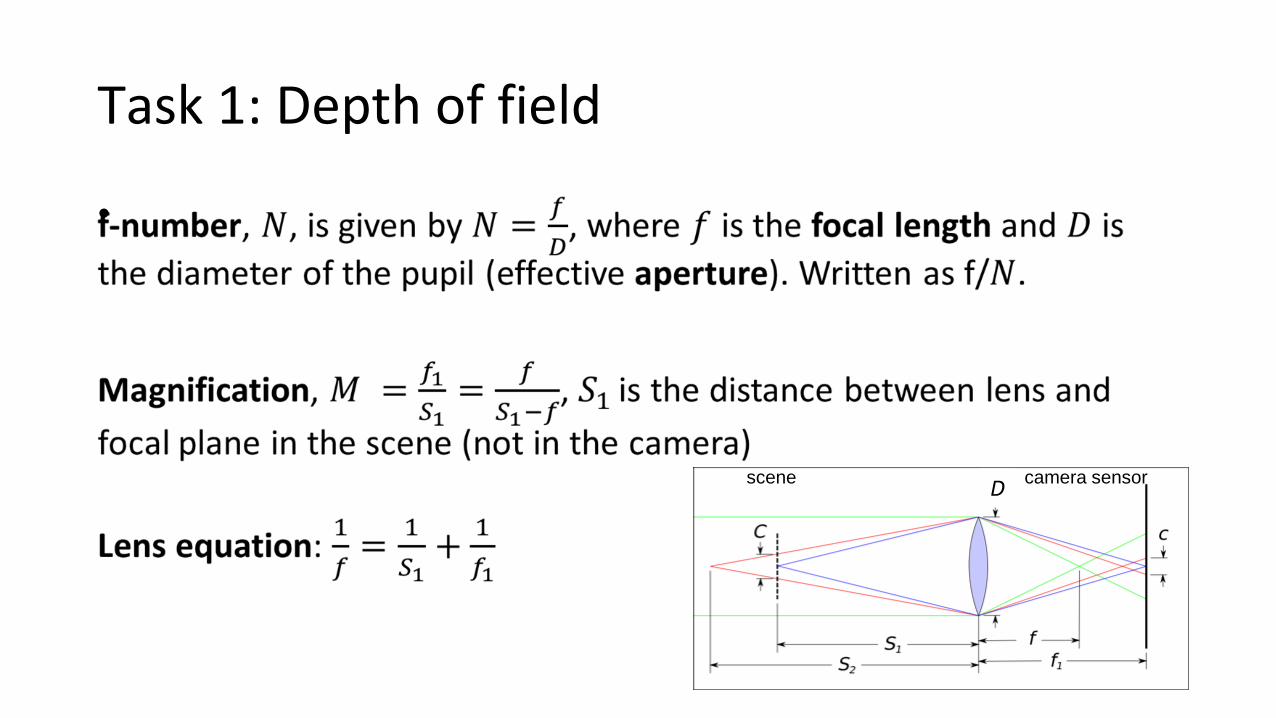
Task 1: Depth of field
•
Dscene camera sensor

Task 1: Depth of field
•
Image is in focus
Image is blurryD

Task 1: Depth of field
•
Image is in focus
Image is blurryD
N is f-number of lens

Task 1: Depth of field• Small f# (N) blur faster
• When focusing far, camera is more depth invariant (f is fixed)
So… why use small f#?

Task 1: Depth of fieldUsing the graph, what is the DOF?
Allowed blur(defined by pixel size and manufacturer)
DoF

Nice visualization
Photography mapped:http://photography-mapped.com/interact.html
Play with the parameters and see what happens!
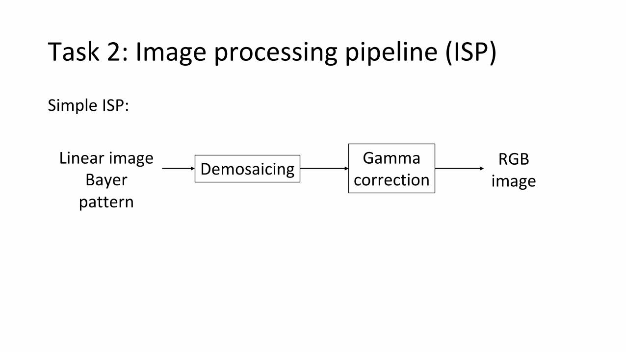
Task 2: Image processing pipeline (ISP)
Simple ISP:
Linear imageBayer
pattern
DemosaicingGamma
correctionRGB
image
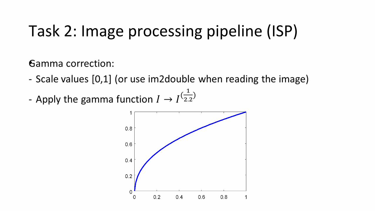
Task 2: Image processing pipeline (ISP)
•

Task 2: Image processing pipeline (ISP)
Demosaicing:
Completing the missing values, for example, red in green pixel
First, find the order of colors in the Bayer pattern
Task 2: Image processing pipeline (ISP)
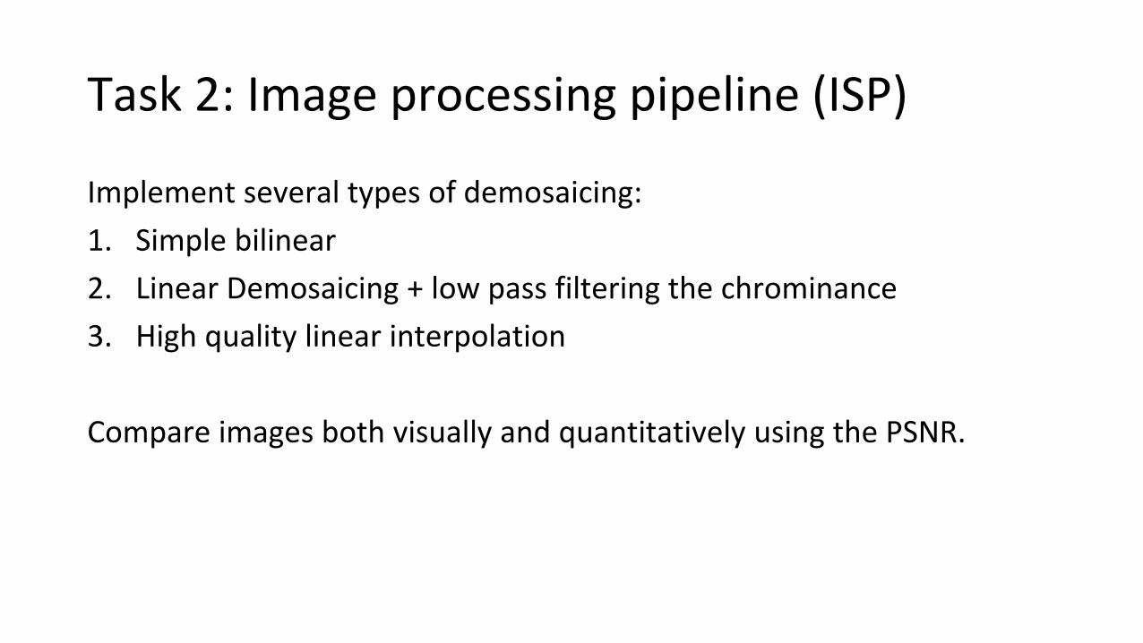
Implement several types of demosaicing:
1. Simple bilinear
2. Linear Demosaicing + low pass filtering the chrominance
3. High quality linear interpolation
Compare images both visually and quantitatively using the PSNR.
Task 2: Image processing pipeline (ISP)
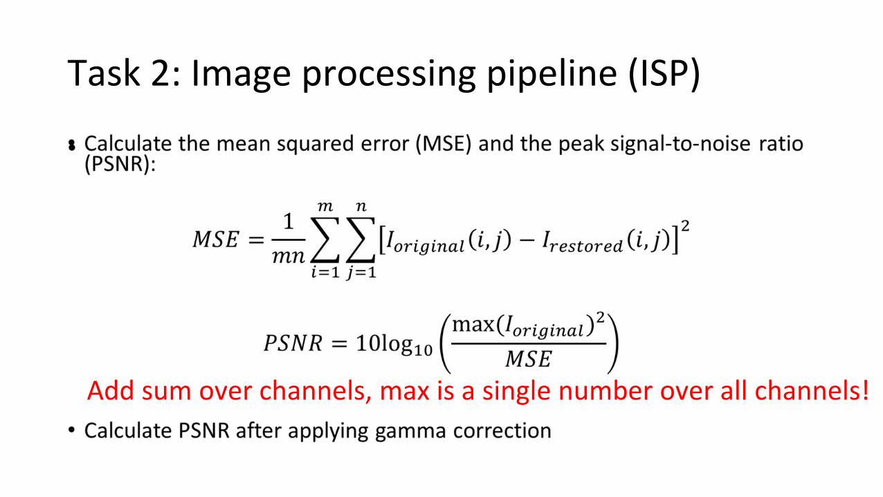
•
Add sum over channels, max is a single number over all channels!
Task 2: Image processing pipeline (ISP)
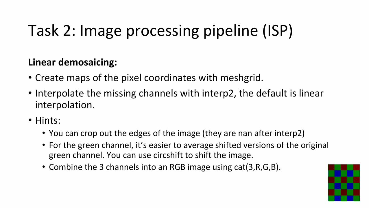
Linear demosaicing:
• Create maps of the pixel coordinates with meshgrid.
• Interpolate the missing channels with interp2, the default is linear interpolation.
• Hints:• You can crop out the edges of the image (they are nan after interp2)
• For the green channel, it’s easier to average shifted versions of the original green channel. You can use circshift to shift the image.
• Combine the 3 channels into an RGB image using cat(3,R,G,B).
Task 2: Image processing pipeline (ISP)
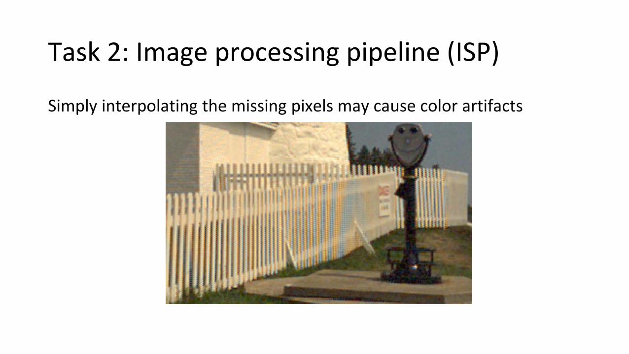
Simply interpolating the missing pixels may cause color artifacts
Task 2: Image processing pipeline (ISP)
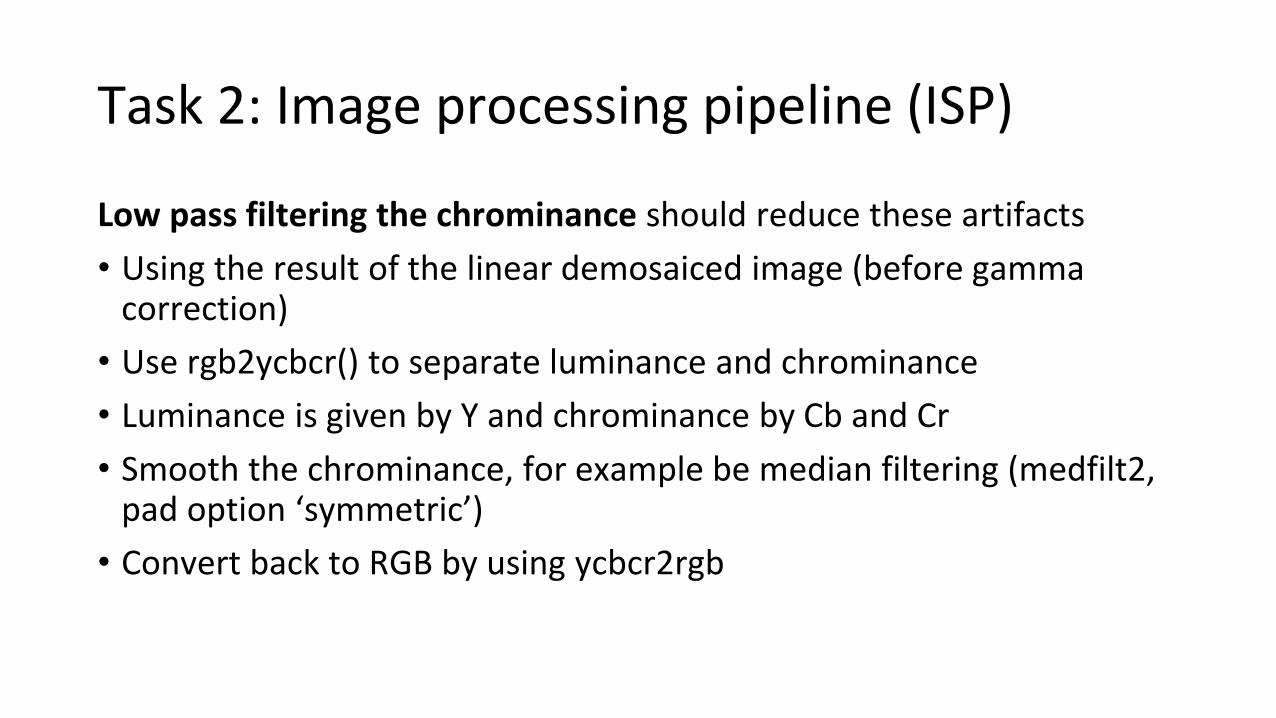
Low pass filtering the chrominance should reduce these artifacts
• Using the result of the linear demosaiced image (before gamma correction)
• Use rgb2ycbcr() to separate luminance and chrominance
• Luminance is given by Y and chrominance by Cb and Cr
• Smooth the chrominance, for example be median filtering (medfilt2, pad option ‘symmetric’)
• Convert back to RGB by using ycbcr2rgb
Task 2: Image processing pipeline (ISP)
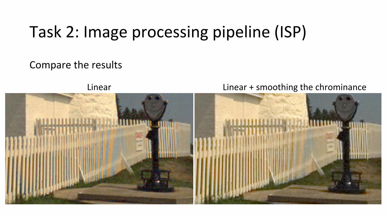
Compare the results
Linear Linear + smoothing the chrominance
Task 2: Image processing pipeline (ISP)
High quality linear interpolation:
• Refer to publication: R. Malvar, L. He, and R. Cutler, "High quality linear interpolation for demosaicing of Bayer-patterned color images", ICASPP, 2004.
• Still linear interpolation, BUT, interpolating one color channel uses information from other color channels.
• Exploiting the correlation among the RGB channels is the main idea for improving demosaicing performance
• Goal: preserve as much detail as possible
Task 2: Image processing pipeline (ISP)
High quality linear interpolation:
• Assumption: edges have much stronger luminance than chrominance components
• → if there is a sharp change in one channel, it probably means there is a sharp luminance change
• Therefore, the change in one channel should be used in the interpolation of the other channels
Task 2: Image processing pipeline (ISP)
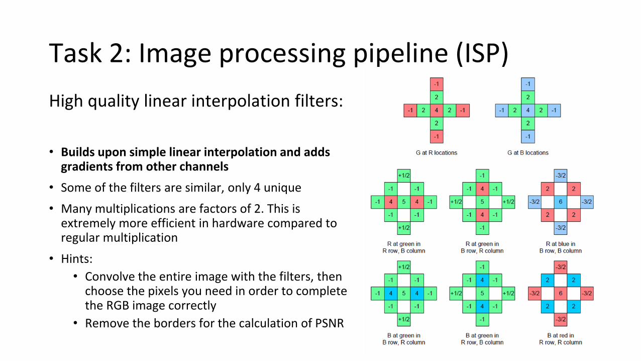
High quality linear interpolation filters:
• Builds upon simple linear interpolation and adds gradients from other channels
• Some of the filters are similar, only 4 unique
• Many multiplications are factors of 2. This is extremely more efficient in hardware compared to regular multiplication
• Hints:
• Convolve the entire image with the filters, then choose the pixels you need in order to complete the RGB image correctly
• Remove the borders for the calculation of PSNR

Task 2: Image processing pipeline (ISP)
Compare the results
Linear High Quality Linear
Are there less or more color artifacts?What about detail?

Task 3: Denoising
•

Task 3: Denoising
Bilateral filtering
A non-linear, edge-preserving and noise-reducing smoothing filter.
The intensity value at each pixel in an image is replaced by a weighted average of intensity values from nearby pixels. The weights depend not only on Euclidean distance of pixels, but also on the radiometric differences.
Spatial weightIntensity weight
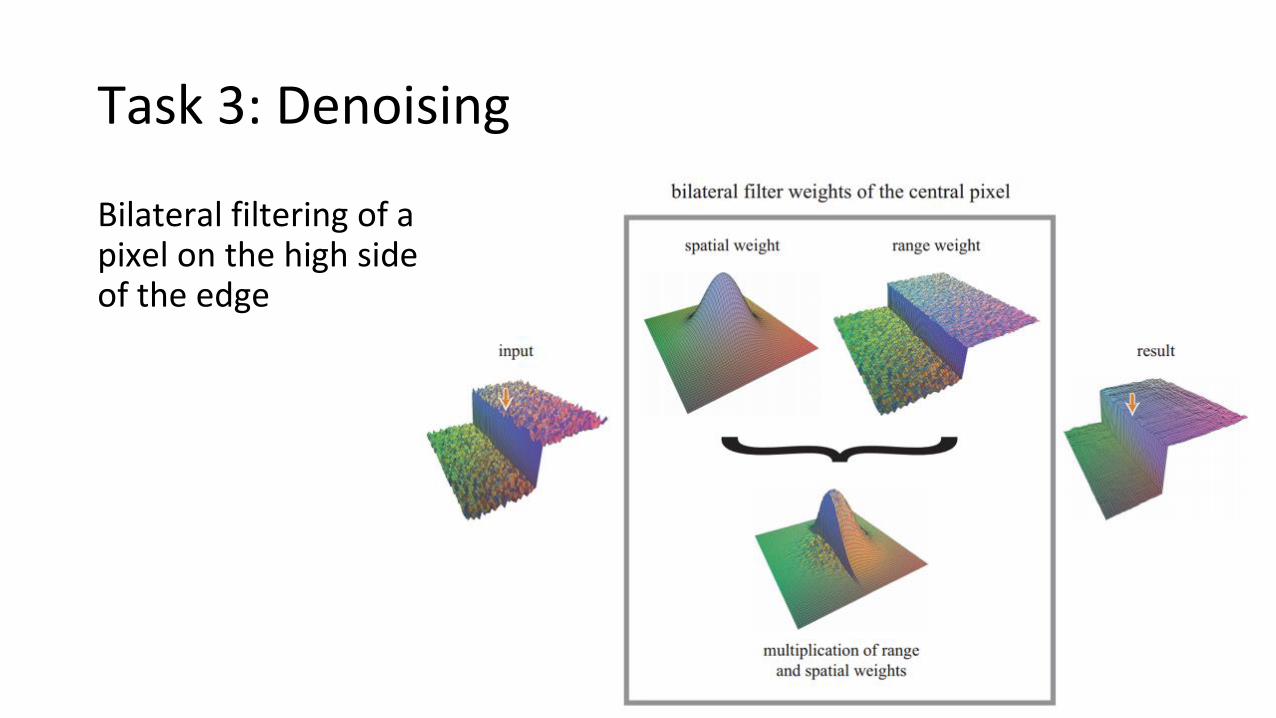
Task 3: Denoising
Bilateral filtering of a pixel on the high side of the edge
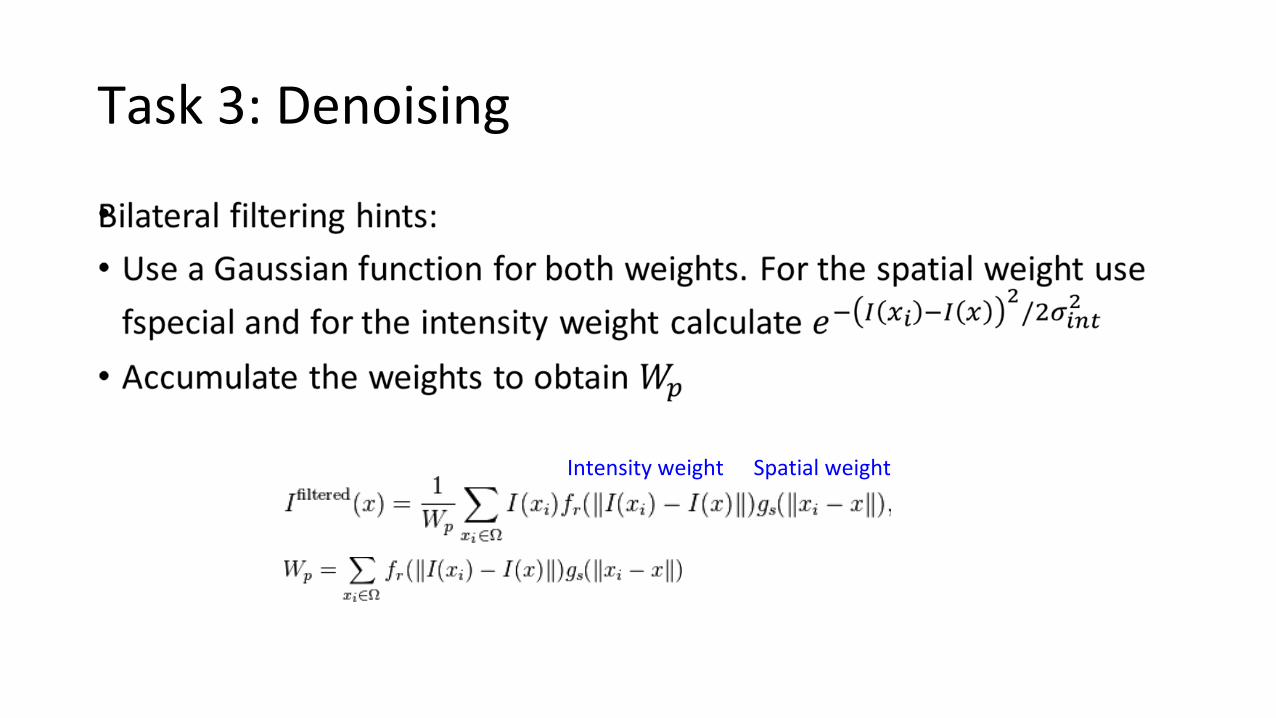
Task 3: Denoising
•
Spatial weightIntensity weight
Task 3: Denoising
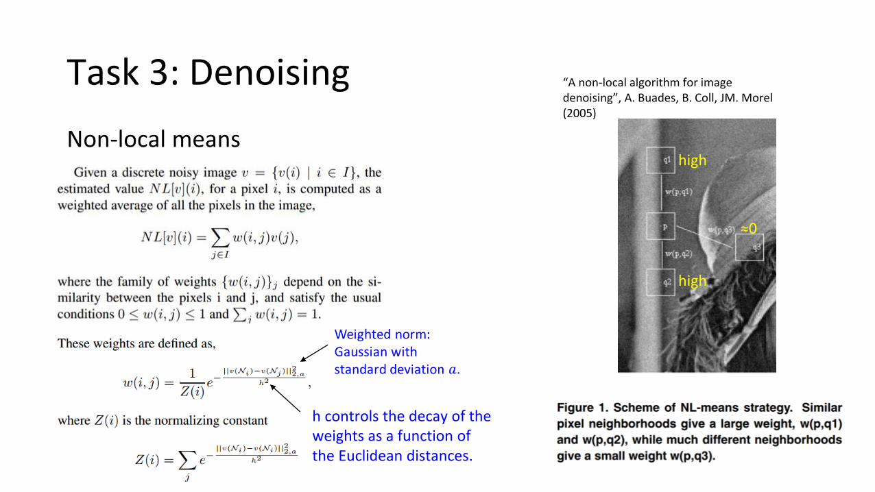
Non-local means
h controls the decay of the weights as a function of the Euclidean distances.
≈0
high
high
“A non-local algorithm for image denoising”, A. Buades, B. Coll, JM. Morel (2005)

Task 3: Denoising
•
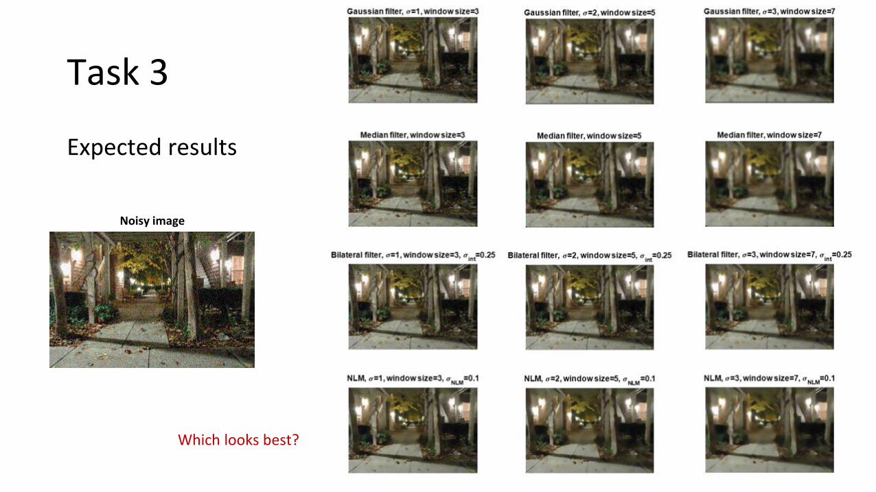
Task 3
Expected results
Noisy image
Which looks best?

Have a nice weekend!And good luck with the homework!