
Proactive Management in Networks and Program …ijiset.com/v1s6/IJISET_V1_I6_08.pdf · IJISET -...
16
IJISET - International Journal of Innovative Science, Engineering & Technology, Vol. 1 Issue 6, August 2014. www.ijiset.com ISSN 2348 – 7968 Abstract The goal of this manuscript is to simulate a company’s network intending to lower its costs with Wide Area Network (WAN) circuits due to short-term upgrades and also implement a monitoring platform to provide a closer monitoring of its network resources such as servers, services, routers, switches, and WAN circuits so that to enable the network administrator to react in a proactive manner. The network design to be described will be homogeneously composed of Cisco router and switch equipment, which will be simulated using a freeware tool called GNS3. The monitoring platform will be based on the integration of two monitoring tools Nagios and Cacti. The combination of both monitoring tools offers high performance and reliability at a low cost for the company. Keywords — Proactive Management, Wide Area Networks, Servers, Routers, Switches, Nagios, Cacti, Reliability. 1. Introduction The rapid growth of medium and large corporation networks, have required network engineers and designers to design low cost network solutions following the most reliable fault tolerant and security features, as well as a proactive monitoring system. Network engineers work along with business units to provide a combination of hardware and software tools that can help business units to lower their costs. This is done with Wide Area Network (WAN) circuit utilization using smart fault tolerant solutions that avoids costly short-term upgrades. For example, a company with multiple remote sites that is dependent on WAN circuit communication such as Multiprotocol Label Switching (MPLS) or Frame Relay (FR) to connect to the company’s datacenter. They have both critical and non-critical applications travelling across the WAN circuit, which often increases the necessity for short-term upgrades on remote sites as well as on the datacenter WAN circuits. As a result, the costs associated with frequent upgrades have increased on an annual basis. Based on the above scenario, we have introduced a new concept in this manuscript, hereby described as PIO (Public Internet Offload), which may be adopted as a key element for any network transformation program. The PIO brings the benefits of network cost control and improved performance by removing Internet destined traffic away from the private WAN, and on to local site Internet breakout. This helps in freeing up capacity on the local remote site private WAN avoiding costly upgrades. The service also supports GRE/IPEC VPN technology with Split Tunneling, called in this paper as IENv5.1 (Internet Enterprise Network) as alternative backup solution, which would enable remote sites to use their local Internet connection for both direct Internet and corporative access. In this paper, the offload device to be implemented at remote sites is based on the Cisco ISR G2 series router. It is also critically important for a company to have a close monitoring of critical IT functions that can save money in network performance, employee productivity and infrastructure cost overruns. This paper also describes the integration of two of the most popular networking monitoring tools in the market Nagios [11] and Cacti [12]. The combination of both the monitoring tools offers high performance and reliability at a low cost for the company. An extensive test bed was created using the freeware network simulator named GNS3 (Graphical Network Simulator). The purpose of this test bed was to reproduce as closest as possible a real network fault tolerance scenario as well as creating a standard model configuration to be applied in different network designs. The entire solution provided in this manuscript would be able to support any strategic requirement to offload non-business critical applications from the corporate WAN onto the Internet at a remote site. The solution may be designed to support medium and large corporations aiming to implement a reliable fault tolerant network environment that can also help to reduce costs with their current WAN solutions as well as implementing a reliable monitoring system. The rest of this paper is organized as follows: Section: 2 outlines our contribution while Section: 3 gives an overview of the various technologies involved in a typical network scenario where PIO is implemented. Section: 4 outlines the various protocols for network monitoring. Section: 5 provides a high level summary of the PIO solution. Section: 6 illustrates the low level PIO solution. Section: 7 briefly explains the testing environment used while Section: 8 provides an in- depth procedure used for PIO monitoring. We conclude in Section: 9. Proactive Management in Networks and Program Performance Vasudevan Janarthanan, Willian Guilherme Department of Information Technology Fairleigh Dickinson University [email protected], [email protected] 51
Transcript of Proactive Management in Networks and Program …ijiset.com/v1s6/IJISET_V1_I6_08.pdf · IJISET -...

IJISET - International Journal of Innovative Science, Engineering & Technology, Vol. 1 Issue 6, August 2014.
www.ijiset.com
ISSN 2348 – 7968
0F Abstract
The goal of this manuscript is to simulate a company’s network intending to lower its costs with Wide Area Network (WAN) circuits due to short-term upgrades and also implement a monitoring platform to provide a closer monitoring of its network resources such as servers, services, routers, switches, and WAN circuits so that to enable the network administrator to react in a proactive manner. The network design to be described will be homogeneously composed of Cisco router and switch equipment, which will be simulated using a freeware tool called GNS3. The monitoring platform will be based on the integration of two monitoring tools Nagios and Cacti. The combination of both monitoring tools offers high performance and reliability at a low cost for the company.
Keywords — Proactive Management, Wide Area Networks, Servers, Routers, Switches, Nagios, Cacti, Reliability. 1. Introduction
The rapid growth of medium and large corporation networks, have required network engineers and designers to design low cost network solutions following the most reliable fault tolerant and security features, as well as a proactive monitoring system. Network engineers work along with business units to provide a combination of hardware and software tools that can help business units to lower their costs. This is done with Wide Area Network (WAN) circuit utilization using smart fault tolerant solutions that avoids costly short-term upgrades. For example, a company with multiple remote sites that is dependent on WAN circuit communication such as Multiprotocol Label Switching (MPLS) or Frame Relay (FR) to connect to the company’s datacenter. They have both critical and non-critical applications travelling across the WAN circuit, which often increases the necessity for short-term upgrades on remote sites as well as on the datacenter WAN circuits. As a result, the costs associated with frequent upgrades have increased on an annual basis. Based on the above scenario, we have introduced a new concept in this manuscript, hereby described as PIO (Public Internet Offload), which may be adopted as a key element for any network transformation program. The PIO brings the benefits of network cost control and improved performance by removing Internet destined traffic away from
the private WAN, and on to local site Internet breakout. This helps in freeing up capacity on the local remote site private WAN avoiding costly upgrades. The service also supports GRE/IPEC VPN technology with Split Tunneling, called in this paper as IENv5.1 (Internet Enterprise Network) as alternative backup solution, which would enable remote sites to use their local Internet connection for both direct Internet and corporative access. In this paper, the offload device to be implemented at remote sites is based on the Cisco ISR G2 series router.
It is also critically important for a company to have a close monitoring of critical IT functions that can save money in network performance, employee productivity and infrastructure cost overruns. This paper also describes the integration of two of the most popular networking monitoring tools in the market Nagios [11] and Cacti [12]. The combination of both the monitoring tools offers high performance and reliability at a low cost for the company. An extensive test bed was created using the freeware network simulator named GNS3 (Graphical Network Simulator). The purpose of this test bed was to reproduce as closest as possible a real network fault tolerance scenario as well as creating a standard model configuration to be applied in different network designs.
The entire solution provided in this manuscript would be able to support any strategic requirement to offload non-business critical applications from the corporate WAN onto the Internet at a remote site. The solution may be designed to support medium and large corporations aiming to implement a reliable fault tolerant network environment that can also help to reduce costs with their current WAN solutions as well as implementing a reliable monitoring system.
The rest of this paper is organized as follows: Section: 2 outlines our contribution while Section: 3 gives an overview of the various technologies involved in a typical network scenario where PIO is implemented. Section: 4 outlines the various protocols for network monitoring. Section: 5 provides a high level summary of the PIO solution. Section: 6 illustrates the low level PIO solution. Section: 7 briefly explains the testing environment used while Section: 8 provides an in-depth procedure used for PIO monitoring. We conclude in Section: 9.
Proactive Management in Networks and Program Performance
Vasudevan Janarthanan, Willian Guilherme
Department of Information Technology Fairleigh Dickinson University
[email protected], [email protected]
51

IJISET - International Journal of Innovative Science, Engineering & Technology, Vol. 1 Issue 6, August 2014.
www.ijiset.com
ISSN 2348 – 7968
2. Contribution
This manuscript simulates a company containing 50 remote sites and one single datacenter. Each site is provided with either a single MPLS WAN circuit or Dual MPLS connection. The Internet traffic of the remote sites is currently centralized in the datacenter, which is currently provided with an OC3 / 155Mbps Internet circuit often upgraded due to Internet access traffic increase. Critical and non-critical applications are currently travelling across the corporate WAN, which often requires short-term upgrades on the branch offices MPLS circuit on the remote sites. As a result the costs associated with frequent MPLS circuit upgrades have increased in an annual basis. The company’s board of director is requiring its network team to come up with a new network and security design solution that may lower the company’s costs with WAN circuits on its branch offices. The board of directors wants to receive information about the ROI (Return on investment) before approving any attempt of modification on the current network design.
The virtual company’s branch office’s Internet traffic currently flows through the MPLS network because the main Internet circuit is centralized in its Datacenter. The purpose of this work is to implement a low cost solution, which may be adopted as a key element of any network transformation program. The solution aims to bring the benefits of network cost control and improved performance by removing Internet destined traffic away from the private WAN, thereby freeing up capacity on the local private WAN (MPLS) avoiding frequent upgrades at the remote sites.
The new solution design supports GRE/IPSEC VPN technology along with ‘Split tunneling’, which will be called in this paper as IENv5.1 (Internet Enterprise Network) as an alternative backup solution to the primary MPLS, which will enable remote sites to use their local Internet connection for both direct Internet and corporative access. The offload device is based on the Cisco ISR G2 series routers. The ISR G2 router requires IOS/license with the security feature set to allow the use of the Zone Based Policy Firewall.
In addition to the new network design, a new monitoring platform will be introduced to keep a close monitoring of the infrastructure. The monitoring service hereby described will be based on the integration of the monitoring tools Nagios and Cacti. The combination of both monitoring tools offers high performance and reliability at a low cost for the company. Nagios and Cacti are both free software distributed via the GPL license. The reason behind using Nagios and Cacti is cost reduction, which is the primary factor in corporate IT today, and because both are currently considered one of the most powerful tools in the market.
3. Background and Related works This section describes the technologies involved in a typical network scenario where PIO is implemented.
3.1 MPLS – Multiprotocol Label Switching
The focus of this paper is not on the MPLS technology; however, we understand it to be important to explain the basic MPLS features and the technology behind it. A traditional Internet Protocol (IP) routing network presents the following drawbacks, which the MPLS addresses:
• Routing protocols are used on all devices to distribute routing information.
• Regardless of the routing protocol, routers always forward packets based on the destination address only.
• Routing lookups are performed on every router. Each router in the network makes an independent decision when forwarding packets.
MPLS helps to reduce the number of routing lookups and can change the forwarding criteria [1]. This capability eliminates the need to run a particular routing protocol on all the devices. MPLS is a switching mechanism that uses labels (numbers) to forward packets. Labels usually correspond to Layer 3 destination addresses (equal to destination-based routing). Labels can also correspond to other parameters like Quality of Service (QoS) and source address. MPLS was designed to support other protocol stacks than IP as well. Label switching is performed regardless of the Layer 3 protocol.
Figure 1: Basic MPLS Example
Figure: 1 illustrates a situation where the intermediary router does not have to perform a time-consuming lookup. Instead this router simply swaps a label with another label (5 is replaced by 3) and forwards the packet based on received label (3). In larger networks the result of MPLS labeling is that only the edge routers perform a routing lookup. All the core routers forward packets based on the labels.
3.2 BGP – Border Gateway Protocol
Companies use either Interior Gateway Protocol (IGP) or static routers as a routing protocol across their internetworks. However, the use of static routes is typically avoided due to its complexity of management, documentation and dynamism [2]. The use of IGP protocols such as OSPF or EIGRP requires
52

IJISET - International Journal of Innovative Science, Engineering & Technology, Vol. 1 Issue 6, August 2014.
www.ijiset.com
ISSN 2348 – 7968
much less planning, configuration and effort in comparison to the use of static routes. The decision of using BGP not often follow the same logic, which as a result leads network engineers and designers to always use an IGP inside their networks.
Border Gateway Protocol (BGP) or more specifically BGP version 4 (BGPv4) advertises, learns, and chooses the best path inside the global Internet [2]. A BGP session established between different Autonomous Systems Number (ASN) is called External Border Gateway Protocol (eBGP). When the BGP session is established between peers inside the same ASN, it is called as Internal Border Gateway Protocol (iBGP).
The iBGP will be extensively used in this solution in order to provide full integration between LAN and WAN environments, which as a result may help companies to standardize the network design through layer 3 protocols implementing a more efficient decision mechanism of routing traffic through the use of dynamic routing protocol. The use of iBGP in the PIO scenario avoids BGP route redistribution inside other IGP protocols such as OSPF or EIGRP, which when performed adds complexity to the network configuration and turns the documentation process extremely difficult. By configuring BGP inside the network, it means that every iBGP router must peer with every other iBGP router. This is also referred to as the full mesh topology. The use of iBGP for full integration between LAN and WAN helps companies to have a fully fault tolerant environment without any manual intervention of the network administrator, since automatic additional attributes may be configured inside the BGP protocol for a full automatized network traffic management.
3.3 GRE – Generic Routing Encapsulation Protocol
Generic Routing Encapsulation (GRE) is a mechanism for encapsulating any network layer protocol in Cisco Systems. The general specification of the GRE protocol is described in the RFC 2784 (previously RFCs 1701 and 1702) [3, 4, 5]. In the general case, a network layer packet, called the payload packet is encapsulated in a GRE packet, which may also include source route information. The resulting GRE packet is then encapsulated in some other network layer protocol, called the delivery protocol, and then forwarded. The GRE protocol does not provide any type of security feature to encrypt the tunneled traffic; instead it depends on a secondary framework such as IPSEC. IPSEC will be briefly introduced in the next section. GRE tunnels, as it is commonly called, allows routing protocols such as RIP and OSPF to forward data packets from one router to another across the Internet. In addition, GRE tunnels can encapsulate multicast data streams for transmission over the Internet.
A company may decide to implement a fault tolerant solution, often called as secondary circuit, using a low cost solution such as GRE over IPSEC. In this paper the GRE feature technology is used in remote sites as a secondary path to reach the datacenter when the MPLS circuit is not available.
Using a typical Cisco router as an example, the basic GRE tunnel diagram would be as shown in Figure: 2,
Figure 2: GRE tunnel example
3.4 IPSEC – IP Security
Many companies have networks located in different geographic locations, and those networks need to communicate securely with one another. Leasing dedicated WAN connections, as for instance, T1 connections using Point-to-Point (PPP) or leasing permanent virtual circuits (PVC) as Frame-Relay, ATM are all options for interconnecting these offices; however, these solutions may become extremely cost prohibitive. IPSEC VPN connections have been considered as a more economical solution for companies. Specifically, an IPSEC VPN can securely transmit data over an untrusted network, such as the Internet.
The PIO solution described in this paper uses IPSEC to encrypt the GRE protocol (GRE over IPSEC), since the GRE does not provide an encryption security feature to protect data when it travels over the Internet. According to Cisco Systems, approximately 40 percent of today’s workforce is located outside of a corporate headquarters location [6]. Some employees work in remote offices, while others telecommute.
The remote employees could connect to the main corporate network using a variety of WAN technologies, as for example, leased lines and PVCs, found in the Frame Relay or ATM networks; however, as previously mentioned, these WAN technologies cost more than the widely available broadband technologies, such as DSL and cable, which might also offer faster speeds. Broadband technologies can be used to support virtual private network (VPN) connections between geographically dispersed offices.
3.5 Firewall
This section gives a brief explanation on firewall technology and its advantages in today’s business and how it helps to protect company’s information. A firewall is basically used to segment a network into different physical subnet work, thereby helping limit the potential damage that could spread from one subnet to another. In network security, a firewall
53

IJISET - International Journal of Innovative Science, Engineering & Technology, Vol. 1 Issue 6, August 2014.
www.ijiset.com
ISSN 2348 – 7968
may be a piece of software or hardware that acts as a barrier between an internal (trusted) network and the external (untrusted) network, such as the Internet.
The PIO prototype solution uses the Cisco Firewall technology to protect the traffic of remote sites called in this project as PIO sites, going towards the Internet. The Internet usage in business today has become increasingly important for growing their business. Hence, it has become crucial to look more closely at the security of their networks as more and more business functions move to the public network. This fact forces companies to ensure that their data and private information is not compromised. For many organizations, in general, the Cisco IOS Firewall meets their needs to provide security if they choose not to use a firewall appliance because of financial constraints or technical complexity. For these organizations, the Cisco IOS Firewall provides a full-featured firewall implemented on Cisco routers using Cisco IOS Software [6].
3.6 Cisco IOS Zone Based Firewall
In common network implementation for branch offices and small sites that belongs to a larger entity, it is common to have two WAN connections. Usually, one is an MPLS, otherwise known as a private connection to the corporate network, and the other is an Internet circuit (often supported with a broadband ADSL circuit), which carries Internet traffic as well as IPSEC VPN tunnels used as backup to the private WAN circuit. Typically, a WAN connection requires dynamic routing capability such as BGP but not many security mechanisms.
On the other hand, Internet connection requires strong and well-designed policy enforcement but no dynamic routing is required since a default route pointing out to the Internet is generally enough. Some organizations may choose to deploy a standalone device to handle each branch office connection. The MPLS connection is terminated at a branch level router, which supports BGP and offers flexible physical interface options. The Internet connection is generally Ethernet based which is terminated on a firewall. The router and the firewall are typically interfaced with one or more layer three switches in the LAN running an IGP protocol. The topology usually adopted by most organizations is a HUB and Spoke topology over WAN. In a HUB spoke scenario, all Spoke sites (also known as remote sites or branches) access hosted services in the Datacenter (also known as HUB). In case remote sites need to access one another, it is normally performed via the WAN circuit.
A new configuration model for Cisco IOS Firewall feature set was introduced by Cisco on the IOS release 12.4(6) T [7]. This new model presented the Cisco IOS zone-based policy. It provides intuitive policies for multiple interface routers, a greater level of granularity with regards to the firewall policy application, and the ability to prohibit traffic between firewall zones until an explicit policy is applied to allow desirable traffic via a default deny-all policy. The new zone-based
policy inspection interface supports almost all the firewall features implemented in previous releases such as stateful packet inspection, application inspection, virtual private network, URL filtering and denial-of-service (DoS) mitigation [7].
Below is a description of a partial output configuration of a typical Zone Based Firewall: The Cisco IOS Zone Based Firewall uses the concept of security zone. Security zone is a group of routed interfaces, which are intended to be treated similarly from a security perspective. For example, if a router has two redundant Internet connections on an edge router, both links could be placed into a shared “untrusted zone”. From a security perspective, it is considered irrelevant about the primary connection and the one used for failover. Connections within an internal network, however, could be assigned to separate trusted zones. Additional zones can be created with different levels of trust which might fall between the two; for instance, a guest wireless network, or corporate extranet.
As was previously mentioned, interfaces are assigned to zones, and inspection policy is applied to traffic moving between the zones. Inter-zone policies offer considerable flexibility and granularity, so different inspection policies can be applied to multiple host groups connected to the same router interface. Firewall policies are configured with the Cisco Policy Language (CPL), which employs a hierarchical structure to define inspection for network protocols and the groups of hosts to which the inspection will be applied.
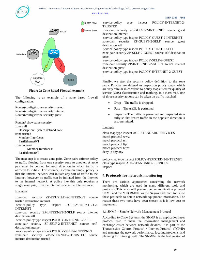
The PIO router initially defines three security zones as in Figure: 3
• The Internet Zone (Internet Connection)
• The Trusted Zone (Corporate Network)
• The Guest Zone (Guest LAN and WLAN)
A special default zone named “self” is also natively pre-defined. This zone applies to traffic, which is originated from, or destined for the control place of the router itself such as for instance routing protocols like SSH, SNMP, etc. By default, all the traffic is allowed to flow into the self-zone.
54
IJISET - International Journal of Innovative Science, Engineering & Technology, Vol. 1 Issue 6, August 2014.
www.ijiset.com
ISSN 2348 – 7968
Figure 3: Zone Based Firewall example
The following is an example of a zone based firewall configuration:
Router(config)#zone security trusted Router(config)#zone security internet Router(config)#zone security guest ! Router# show zone security zone self Description: System defined zone zone trusted Member Interfaces: FastEthernet0/1 zone internet
Member Interfaces: FastEthernet0/0
The next step is to create zone pairs. Zone pairs enforce policy to traffic flowing from one security zone to another. A zone pair must be defined for each direction in which traffic is allowed to initiate. For instance, a common simple policy is that the internal network can initiate any sort of traffic to the Internet; however no traffic can be initiated from the Internet to the internal network. A policy like this only requires a single zone pair, from the internal zone to the Internet zone.
UExample U:
zone-pair security ZP-TRUSTED-2-INTERNET source trusted destination internet service-policy type inspect POLICY-TRUSTED-2-INTERNET zone-pair security ZP-INTERNET-2-SELF source internet destination self service-policy type inspect POLICY-INTERNET-2-SELF zone-pair security ZP-SELF-2-INTERNET source self-destination internet service-policy type inspect POLICY-SELF-2-INTERNET zone-pair security ZP-INTERNET-2-TRUSTED source internet destination trusted
service-policy type inspect POLICY-INTERNET-2-TRUSTED zone-pair security ZP-GUEST-2-INTERNET source guest destination internet service-policy type inspect POLICY-GUEST-2-INTERNET zone-pair security ZP-GUEST-2-SELF source guest destination self service-policy type inspect POLICY-GUEST-2-SELF zone-pair security ZP-SELF-2-GUEST source self-destination guest service-policy type inspect POLICY-SELF-2-GUEST zone-pair security ZP-INTERNET-2-GUEST source internet destination guest service-policy type inspect POLICY-INTERNET-2-GUEST !
Finally, we start the security policy definition to the zone pairs. Policies are defined as inspection policy maps, which are very similar in construct to policy maps used for quality of service (QoS) classification and marking. In a class map, one of three security actions can be taken on traffic matched:
• Drop – The traffic is dropped.
• Pass – The traffic is permitted.
• Inspect – The traffic is permitted and inspected state fully so that return traffic in the opposite direction is also permitted.
UExample U:
class-map type inspect ACL-STANDARD-SERVICES match protocol www match protocol ssh match protocol ftp match protocol https deny ip any any ! policy-map type inspect POLICY-TRUSTED-2-INTERNET class type inspect ACL-STANDARD-SERVICES inspect
4. Protocols for network monitoring
There are various approaches concerning the network monitoring, which are used in many different tools and protocols. This work will present the communication protocol SNMP and the MIB RMON, as the Nagios and Cacti tools use these protocols to obtain network equipment information. The reason these two tools have been chosen is it is low cost to implement. 4.1 SNMP – Simple Network Management Protocol
According to Cisco Systems, the SNMP is an application layer protocol used to make the information management and exchange easier between network devices. It is part of the Transmission Control Protocol / Internet Protocol (TCP/IP) and manages the network performance, locating problems, and planning for future growth. The SNMPv3 is the last version of
55

IJISET - International Journal of Innovative Science, Engineering & Technology, Vol. 1 Issue 6, August 2014.
www.ijiset.com
ISSN 2348 – 7968
the protocol, and offer more resources such as encryption, differently of previous versions [10].
4.2 Basic SNMP Components
A SNMP managed network is broken down into three components: SNMP Manager: The SNMP manager monitors and control the devices within the network using SNMP. Examples of managed devices are servers, switches, routers, printers, bridges. SNMP Agent: The SNMP agent is a software component that runs directly on the managed device and plays the role of a data translator. In order for the data to be obtained and interpreted by the SNMP Manager, the data needs to be in a correct format, and follow the SNMP pattern. MIB – Management Information Base is a virtual information storage location that contains collections of managed objects. Within the MIB, there are objects related to different defined MIB modules example, the interface module).
Figure 4: SNMP Management and Agent
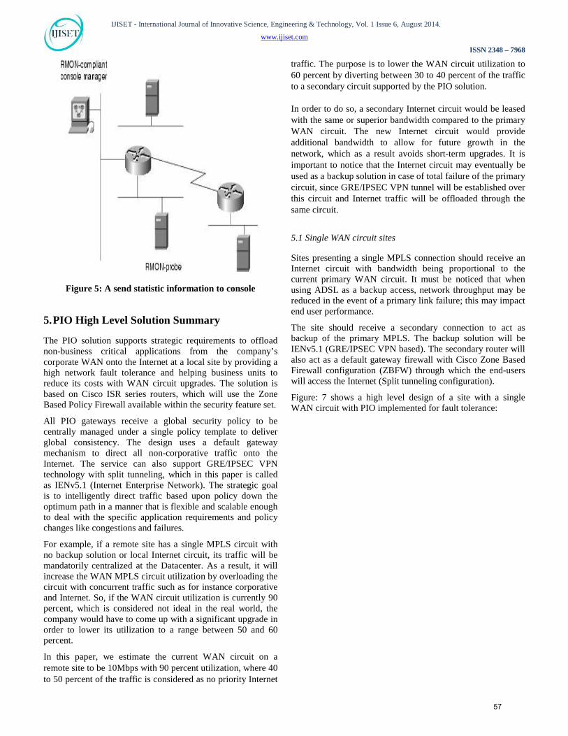
Figure 5 represents the process of data collection through the management system (top) and how agents (middle) are enabled on the three managed devices in this example. The MIBs are a collection of information organized hierarchically and that are accessed by protocols such as the SNMP. The MIBs are composed of managed objects and are identified individually by IDs. A more in-depth
discussion on the functioning of the MIBs is out of the scope of this manuscript. According to the SNMP evolution, new functionalities and operations were implemented; however, in a basic form these operations are divided in the following way:
- Read – This command is used by the management
system to monitor the devices, in which any correspondent variable in each object is examined.
- Write – This command is used to control the managed device. The management system can sometimes change values of the managed devices.
- Trap – This command is used by the managed device to report events to the management system in case something occurs. The write command is only provided on the SNMPv3 [10] version.
4.3 RMON – Remote Network Monitoring
The RMON (Remote Network Monitoring) is actually a MIB based on SNMP, which was developed by the IETF (Internet Engineering Task Force). The purpose was to support the monitoring and analyzes of LAN protocols. According to Cisco Systems, the current version (RMON2) supports the physical, data, network, and application layers. RMON agents usually come installed by default on many of the network equipment [10].
RMON was designed to work in a different way compared to other SNMP based systems. For example, Devices located in strategic network points play an important role as “probes” that capture and store data through the SNMP (see figure 4). These data will be sent to the management system only when required, which makes such probes require a considerable amount of resources. In other words, the RMON monitoring focuses mainly based on flow, while other tools focus on the device status (Ex: Nagios). A RMON2 MIB consists of 9 groups or categories of data that can be extracted and organized; however, in many implementations, only some are used if we consider the performance.
56
IJISET - International Journal of Innovative Science, Engineering & Technology, Vol. 1 Issue 6, August 2014.
www.ijiset.com
ISSN 2348 – 7968
Figure 5: A send statistic information to console
5. PIO High Level Solution Summary
The PIO solution supports strategic requirements to offload non-business critical applications from the company’s corporate WAN onto the Internet at a local site by providing a high network fault tolerance and helping business units to reduce its costs with WAN circuit upgrades. The solution is based on Cisco ISR series routers, which will use the Zone Based Policy Firewall available within the security feature set.
All PIO gateways receive a global security policy to be centrally managed under a single policy template to deliver global consistency. The design uses a default gateway mechanism to direct all non-corporative traffic onto the Internet. The service can also support GRE/IPSEC VPN technology with split tunneling, which in this paper is called as IENv5.1 (Internet Enterprise Network). The strategic goal is to intelligently direct traffic based upon policy down the optimum path in a manner that is flexible and scalable enough to deal with the specific application requirements and policy changes like congestions and failures.
For example, if a remote site has a single MPLS circuit with no backup solution or local Internet circuit, its traffic will be mandatorily centralized at the Datacenter. As a result, it will increase the WAN MPLS circuit utilization by overloading the circuit with concurrent traffic such as for instance corporative and Internet. So, if the WAN circuit utilization is currently 90 percent, which is considered not ideal in the real world, the company would have to come up with a significant upgrade in order to lower its utilization to a range between 50 and 60 percent.
In this paper, we estimate the current WAN circuit on a remote site to be 10Mbps with 90 percent utilization, where 40 to 50 percent of the traffic is considered as no priority Internet
traffic. The purpose is to lower the WAN circuit utilization to 60 percent by diverting between 30 to 40 percent of the traffic to a secondary circuit supported by the PIO solution. In order to do so, a secondary Internet circuit would be leased with the same or superior bandwidth compared to the primary WAN circuit. The new Internet circuit would provide additional bandwidth to allow for future growth in the network, which as a result avoids short-term upgrades. It is important to notice that the Internet circuit may eventually be used as a backup solution in case of total failure of the primary circuit, since GRE/IPSEC VPN tunnel will be established over this circuit and Internet traffic will be offloaded through the same circuit.
5.1 Single WAN circuit sites
Sites presenting a single MPLS connection should receive an Internet circuit with bandwidth being proportional to the current primary WAN circuit. It must be noticed that when using ADSL as a backup access, network throughput may be reduced in the event of a primary link failure; this may impact end user performance.
The site should receive a secondary connection to act as backup of the primary MPLS. The backup solution will be IENv5.1 (GRE/IPSEC VPN based). The secondary router will also act as a default gateway firewall with Cisco Zone Based Firewall configuration (ZBFW) through which the end-users will access the Internet (Split tunneling configuration).
Figure: 7 shows a high level design of a site with a single WAN circuit with PIO implemented for fault tolerance:
57

IJISET - International Journal of Innovative Science, Engineering & Technology, Vol. 1 Issue 6, August 2014.
www.ijiset.com
ISSN 2348 – 7968
Figure 6: High Level Design of a sample Single WAN
circuit site
5.2 Dual WAN circuit sites
According to the priority definition of the site, the company requires that such a site be provided with two WAN connections (Primary and Secondary); however, the secondary connection is used only in case of complete unavailability of the primary, which means that this circuit is used only in case of emergency. The solution to be designed in this case may vary from the potential decommissioning of the secondary WAN circuit to simply adding a low cost PIO solution. Internet access sites under these circumstances should be sized with a minimum download speed equivalent of 50 percent of the primary WAN access speed.
• Option 1: The secondary WAN circuit may be decommissioned. In this case an alternative backup solution based on the previously mentioned IENv5.1 technology can be implemented along with a standard PIO configuration. The site will be described as IEN/PIO site.
• Option 2: The secondary WAN circuit may be kept in place. This option should be adopted in case fines are applicable due to cancellation of the secondary WAN circuit under a valid lease contract. In this situation the site
may still receive the PIO solution and it will be called as PIO site ONLY. Refer Figure: 6.
Figure 7: High Level Design of a sample Dual WAN circuit
site
5.3 LAN and WAN Integration
58
IJISET - International Journal of Innovative Science, Engineering & Technology, Vol. 1 Issue 6, August 2014.
www.ijiset.com
ISSN 2348 – 7968
In order to provide a full integration between LAN and WAN environment, we utilize iBGP protocol between LAN and WAN. iBGP protocol should be configured among all layer 3 devices inside the LAN responsible for routing decision.
Some of the advantages in this scenario are:
• Standardization of design integration between LAN and WAN through layer 3.
• More efficiency in the decision of routing traffic through the use of dynamic routing protocol.
• More stability and reliability in failover environment with the possibility of fault identification physical and logical.
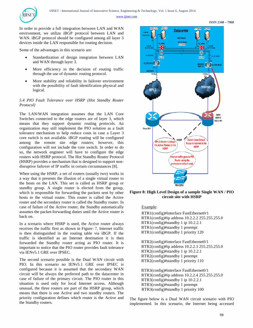
5.4 PIO Fault Tolerance over HSRP (Hot Standby Router Protocol)
The LAN/WAN integration assumes that the LAN Core Switches connected to the edge routers are of layer 3, which means that they support dynamic routing protocols. An organization may still implement the PIO solution as a fault tolerance mechanism to help reduce costs in case a Layer 3 core switch is not available. iBGP routing will be configured among the remote site edge routers; however, this configuration will not include the core switch. In order to do so, the network engineer will have to configure the edge routers with HSRP protocol. The Hot Standby Router Protocol (HSRP) provides a mechanism that is designed to support non-disruptive failover of IP traffic in certain circumstances [8].
When using the HSRP, a set of routers (usually two) works in a way that it presents the illusion of a single virtual router to the hosts on the LAN. This set is called as HSRP group or standby group. A single router is elected from the group, which is responsible for forwarding the packets sent by other hosts to the virtual router. This router is called the Active router and the secondary router is called the Standby router. In case of failure of the Active router, the Standby automatically assumes the packet-forwarding duties until the Active router is back on.
In a scenario where HSRP is used, the Active router always receives the traffic first as shown in Figure: 7. Internet traffic is then distinguished in the routing table via iBGP. If the traffic is identified as an Internet destination it is then forwarded the Standby router acting as PIO router. It is important to notice that the PIO router provides fault tolerance via IENv5.1 GRE over IPSEC.
The second scenario possible is the Dual WAN circuit with PIO. In this scenario no IENv5.1 GRE over IPSEC is configured because it is assumed that the secondary WAN circuit will be always the preferred path to the datacenter in case of failure of the primary circuit. The PIO router in this situation is used only for local Internet access. Although unusual, the three routers are part of the HSRP group, which means that there is one Active and two standby routers. The priority configuration defines which router is the Active and the Standby routers.
Figure 8: High Level Design of a sample Single WAN / PIO
circuit site with HSRP
UExample U:
RTR1(config)#interface FastEthernet0/1 RTR1(config)#ip address 10.2.2.2 255.255.255.0 RTR1(config)#standby 1 ip 10.2.2.1 RTR1(config)#standby 1 preempt RTR1(config)#standby 1 priority 120 RTR2(config)#interface FastEthernet0/1 RTR2(config)#ip address 10.2.2.3 255.255.255.0 RTR2(config)#standby 1 ip 10.2.2.1 RTR2(config)#standby 1 preempt RTR2(config)#standby 1 priority 110 RTR3(config)#interface FastEthernet0/1 RTR3(config)#ip address 10.2.2.4 255.255.255.0 RTR3(config)#standby 1 ip 10.2.2.1 RTR3(config)#standby 1 preempt
RTR3(config)#standby 1 priority 100
The figure below is a Dual WAN circuit scenario with PIO implemented. In this scenario, the Internet being accessed
59

IJISET - International Journal of Innovative Science, Engineering & Technology, Vol. 1 Issue 6, August 2014.
www.ijiset.com
ISSN 2348 – 7968
locally instead of entering the WAN circuit and causing traffic concurrency.
Figure 9: High Level Design of a sample Dual WAN / PIO
circuit site with HSRP
6. PIO Low Level Solution
This section presents a low level configuration for the design of the prototype network along with all technical aspects involved in the implementation level.
6.1 Datacenter Configuration
The datacenter configuration is common to any remote site as shown in Figure: 9. It means that the site is completely prepared to receive connections either from Single WAN sites with IENv5.1 connections or Dual WAN sites.
Figure 10: Low Level Design of the Datacenter
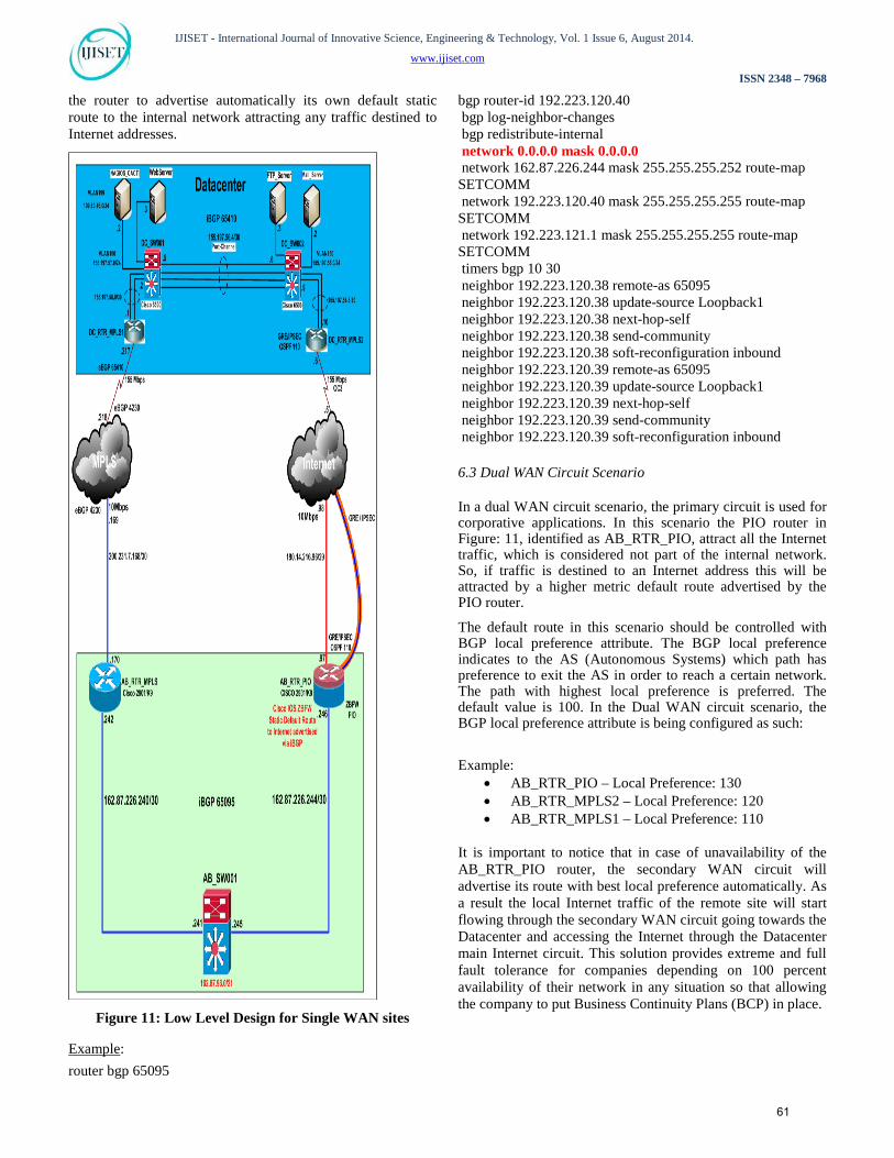
6.2 Single WAN Circuit Scenario
In a single WAN circuit scenario as the one displayed in Figure: 10, the primary WAN circuit is used for corporate applications. In a regular scenario with no PIO implemented, the Internet traffic would be flowing through the WAN circuit creating concurrent traffic with high priority applications, which would require the company to implement extreme complex QoS configuration in order to guarantee specific bandwidth amount for important applications. Once the PIO is implemented, the Internet traffic is then offloaded from the WAN circuit diverting it to the local Internet circuit.
In this scenario, the PIO router identified as AB_RTR_PIO in Figure: 10, is configured with BGP protocol, which is configured to advertise a default Internet route with higher priority than any other default route inside the LAN. Therefore, if traffic is destined to an Internet address, this will be attracted by a higher default route metric advertised by the PIO router.
Notice that both routers in the diagram (AB_RTR_MPLS and AB_RTR_PIO) advertise its own default routes so that in case of unavailability of the AB_RTR_PO router, the AB_RTR_MPLS router injects its route automatically into the internal network to attract end-users Internet traffic. The default route is being internally controlled via BGP protocol. On the AB_RTR_PIO router the command “network 0.0.0.0 mask 0.0.0.0” is used for configuration. This command makes
60
IJISET - International Journal of Innovative Science, Engineering & Technology, Vol. 1 Issue 6, August 2014.
www.ijiset.com
ISSN 2348 – 7968
the router to advertise automatically its own default static route to the internal network attracting any traffic destined to Internet addresses.
Figure 11: Low Level Design for Single WAN sites
UExample U:
router bgp 65095
bgp router-id 192.223.120.40 bgp log-neighbor-changes bgp redistribute-internal network 0.0.0.0 mask 0.0.0.0 network 162.87.226.244 mask 255.255.255.252 route-map SETCOMM network 192.223.120.40 mask 255.255.255.255 route-map SETCOMM network 192.223.121.1 mask 255.255.255.255 route-map SETCOMM timers bgp 10 30 neighbor 192.223.120.38 remote-as 65095 neighbor 192.223.120.38 update-source Loopback1 neighbor 192.223.120.38 next-hop-self neighbor 192.223.120.38 send-community neighbor 192.223.120.38 soft-reconfiguration inbound neighbor 192.223.120.39 remote-as 65095 neighbor 192.223.120.39 update-source Loopback1 neighbor 192.223.120.39 next-hop-self neighbor 192.223.120.39 send-community neighbor 192.223.120.39 soft-reconfiguration inbound
6.3 Dual WAN Circuit Scenario
In a dual WAN circuit scenario, the primary circuit is used for corporative applications. In this scenario the PIO router in Figure: 11, identified as AB_RTR_PIO, attract all the Internet traffic, which is considered not part of the internal network. So, if traffic is destined to an Internet address this will be attracted by a higher metric default route advertised by the PIO router.
The default route in this scenario should be controlled with BGP local preference attribute. The BGP local preference indicates to the AS (Autonomous Systems) which path has preference to exit the AS in order to reach a certain network. The path with highest local preference is preferred. The default value is 100. In the Dual WAN circuit scenario, the BGP local preference attribute is being configured as such:
Example:
• AB_RTR_PIO – Local Preference: 130 • AB_RTR_MPLS2 – Local Preference: 120 • AB_RTR_MPLS1 – Local Preference: 110
It is important to notice that in case of unavailability of the AB_RTR_PIO router, the secondary WAN circuit will advertise its route with best local preference automatically. As a result the local Internet traffic of the remote site will start flowing through the secondary WAN circuit going towards the Datacenter and accessing the Internet through the Datacenter main Internet circuit. This solution provides extreme and full fault tolerance for companies depending on 100 percent availability of their network in any situation so that allowing the company to put Business Continuity Plans (BCP) in place.
61

IJISET - International Journal of Innovative Science, Engineering & Technology, Vol. 1 Issue 6, August 2014.
www.ijiset.com
ISSN 2348 – 7968
Figure 12: Low Level Design for Dual WAN sites
7. Test environment
Both scenarios have been extensively tested in a virtual environment using an open source Cisco Network Simulator called GNS 3 (Graphical Network Simulator). GNS3 is an open source software that makes the simulation of complex networks allowing to reproduce as close as possible the way a real network performs without having a dedicated network hardware such as routers and switches. The software provides an intuitive graphical user interface to design and configure virtual networks running on traditional PC hardware and may be used on multiple operating systems such as Windows, Linux and MacOS X [9].
8. Monitoring platform integration 8.1 Solution Monitoring using Nagios and Cacti
The PIO monitoring solution is provided through the integration of two popular tools Nagios and Cacti, which are also low cost monitoring solution for computational and network resources. Both tools are free and are rated among the best in the market, providing quality at a low cost. One point that should be highlighted about the Nagios Core platform is that a company may choose between four different software editions as shown in figure 14 below.
Figure 13: Nagios Core Versions
The reason for the integration between the two tools is because they offer different resources. Nagios uses an alert system that keeps the administrator informed of the status of the network and computing resources, while Cacti uses this data to generate graphs, which facilitates the understanding of the real situation of the network, helps with capacity planning, creates executive reports among other features. We will now discuss Nagios and Cacti in detailed in order to have a broader picture of how this solution fits into the entire PIO network environment, by helping companies to keep a close monitoring of their networks, to ensure reliability, fault-tolerance and a smart capacity planning of their network at a low cost. 8.2 Nagios Monitoring Tool
62
IJISET - International Journal of Innovative Science, Engineering & Technology, Vol. 1 Issue 6, August 2014.
www.ijiset.com
ISSN 2348 – 7968
Nagios is distributed via GPL license, created by Ethan Galstad. Currently a large community of developers around the world participates in the development of this tool that came up with the name Netsaint in the 90s. The NetSaint was only a small DOS tool that was used to “ping” command to test connectivity to Novell servers. This application could also be used for third-party applications and data rescue, arranging them in text files. This is the beginning of architecture Server-Plugins, used by Nagios, which resulted in a huge success tool. In 1998, Ethan launched an enhanced version of NetSaint to make it work on Linux platform. This version has been optimized so that it could monitor hosts and services effectively. In 2002, due to problems with the naming rights NetSaint, Galstad renamed the tool to Nagios, and from this point on; the software has become increasingly known internationally. In recent years, Nagios has won many awards and has been used on a large scale, especially by large companies such as ISPs (Internet Service Providers), due to its robustness and scalability. 8.3 Nagios Operation One of the main purposes of a monitoring system is to detect malfunctions of machinery and services, so that the administrator is notified immediately about the problem [12]. The Nagios system does not perform its functions by itself. It uses plugins to perform the necessary checks by using an extremely flexible structure. The administrator may develop plugins in any programming language in order to support specific business needs. The objects monitored by the Nagios system can be divided into two basic categories:
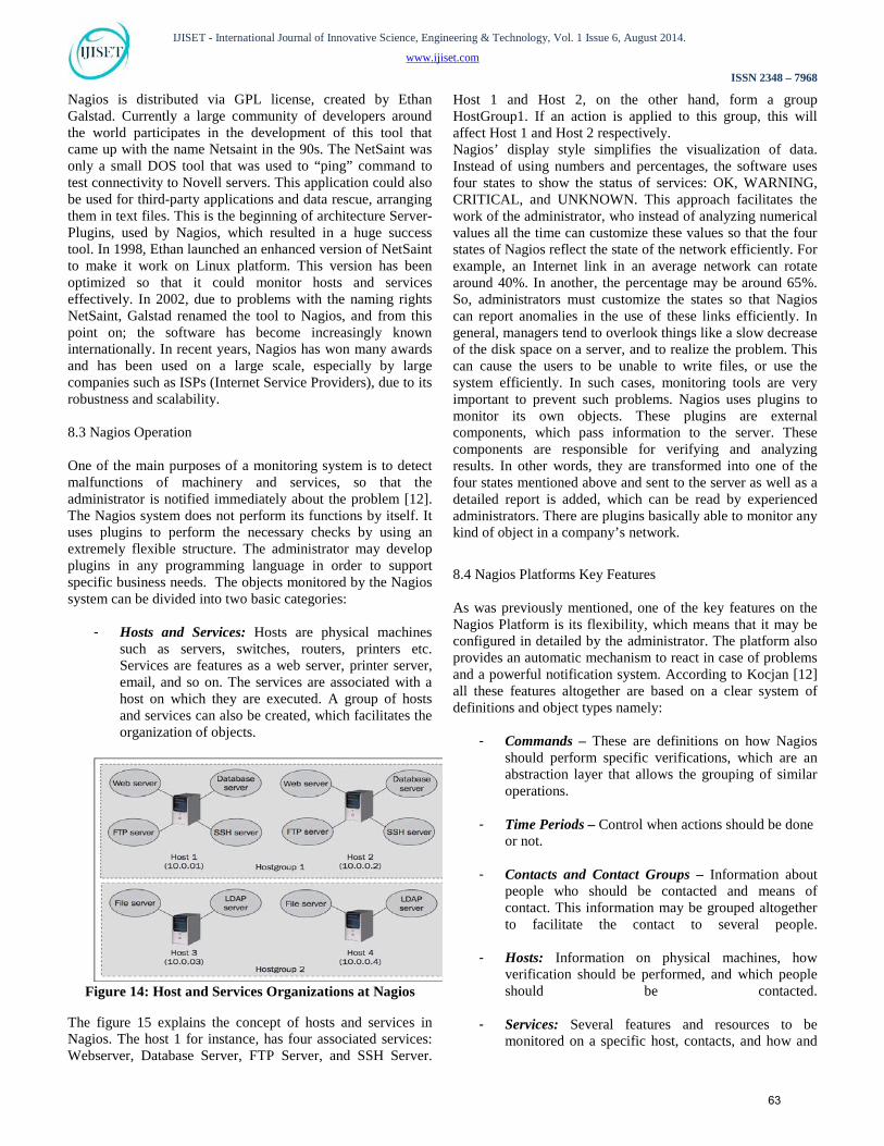
- Hosts and Services: Hosts are physical machines
such as servers, switches, routers, printers etc. Services are features as a web server, printer server, email, and so on. The services are associated with a host on which they are executed. A group of hosts and services can also be created, which facilitates the organization of objects.
Figure 14: Host and Services Organizations at Nagios
The figure 15 explains the concept of hosts and services in Nagios. The host 1 for instance, has four associated services: Webserver, Database Server, FTP Server, and SSH Server.
Host 1 and Host 2, on the other hand, form a group HostGroup1. If an action is applied to this group, this will affect Host 1 and Host 2 respectively. Nagios’ display style simplifies the visualization of data. Instead of using numbers and percentages, the software uses four states to show the status of services: OK, WARNING, CRITICAL, and UNKNOWN. This approach facilitates the work of the administrator, who instead of analyzing numerical values all the time can customize these values so that the four states of Nagios reflect the state of the network efficiently. For example, an Internet link in an average network can rotate around 40%. In another, the percentage may be around 65%. So, administrators must customize the states so that Nagios can report anomalies in the use of these links efficiently. In general, managers tend to overlook things like a slow decrease of the disk space on a server, and to realize the problem. This can cause the users to be unable to write files, or use the system efficiently. In such cases, monitoring tools are very important to prevent such problems. Nagios uses plugins to monitor its own objects. These plugins are external components, which pass information to the server. These components are responsible for verifying and analyzing results. In other words, they are transformed into one of the four states mentioned above and sent to the server as well as a detailed report is added, which can be read by experienced administrators. There are plugins basically able to monitor any kind of object in a company’s network.
8.4 Nagios Platforms Key Features As was previously mentioned, one of the key features on the Nagios Platform is its flexibility, which means that it may be configured in detailed by the administrator. The platform also provides an automatic mechanism to react in case of problems and a powerful notification system. According to Kocjan [12] all these features altogether are based on a clear system of definitions and object types namely:
- Commands – These are definitions on how Nagios should perform specific verifications, which are an abstraction layer that allows the grouping of similar operations.
- Time Periods – Control when actions should be done or not.
- Contacts and Contact Groups – Information about people who should be contacted and means of contact. This information may be grouped altogether to facilitate the contact to several people.
- Hosts: Information on physical machines, how verification should be performed, and which people should be contacted.
- Services: Several features and resources to be monitored on a specific host, contacts, and how and
63

IJISET - International Journal of Innovative Science, Engineering & Technology, Vol. 1 Issue 6, August 2014.
www.ijiset.com
ISSN 2348 – 7968
when the verification should be made.
- Hierarchy notifications for hosts and services – Define periods in which additional persons must be notified. For example, if a mission critical server is offline for more than four hours, management may be notified.
Another very important feature of Nagios is the advanced system of system dependencies. For example, if a router is offline, all machinery and services accessible through this device are obviously affected. Some systems do not take this into account, resulting in a large amount of notifications about all the machines and services affected.
Figure 8 illustrates the Nagios notification system. In this example, Switch 1 is offline, so Nagios does not monitor the Router 1 and other equipment and dependent services.
Figure 15: Nagios System Dependency
8.5 Monitoring Network Resources with Nagios There are two cases regarding the monitoring of hosts in the Nagios platform: Windows and Linux hosts. The way in which the tracking is done changes in some aspects: - Linux hosts: The NRPE add-on is installed so that Nagios plugins could run on remote hosts. If the NRPE is not installed, Nagios cannot have access to internal resources of the system as processor, RAM, and disk space usage. Another alternative would be to use SSH (Secure Shell) to perform remote connections in order to obtain information through native command system, sending the information to the Nagios server, but the process is very intense, making it
unfeasible if there is a large number of hosts and services to be monitored. Figure 10 shows the logic operation of NRPE.
Figure 16: Representation of the NRPE operation
The Nagios server runs the check_nrpe plugin that requires the data to the add-on NRPE installed on the remote host. The add-on in turn, obtains data on disk usage, CPU etc… and sends it to the server. The process of installing NRPE is not treated in this work, but can be found on the official Nagios website. - Windows hosts: In this case, the use of the NSClient++ agent is needed. This small software sends the information to the Nagios server, which processes it through check_nt plugin. Figure 13 illustrates the operation of the agent.
Figure 17: Representation of the NSClient++ operation
The plugin check_nt queries the agent NSClient++ in search of information about CPU, RAM memory, disk space, running processes and services.
- Internet and MPLS Links - This feature does not require the use of add-ons or agents. The plugin check_snmp uses the ICMP (Internet Control Message Protocol) to test connectivity between end devices and the routers used in network. If there is need for information about port status and traffic statistics such as packet loss, for example, the machine must support SNMP function, which must be enabled and configured. The check_snmp operating logic can be seen in Figure 14.
64
IJISET - International Journal of Innovative Science, Engineering & Technology, Vol. 1 Issue 6, August 2014.
www.ijiset.com
ISSN 2348 – 7968
Figure 18: Representation of the operation of the plugin
check_snmp
8.6 Cacti Tool
Cacti is a free tool, which means that there is no cost with licenses. Traditionally, the graphic plotting is made using data obtained via SNMP, but other sources may be used, such as Shell or Perl Script. There are several reasons why Cacti is a powerful tool for the administrator, including:
- It is easy to install and does not require advanced knowledge of operating systems for a basic setup.
- Do not require many packages as prerequisites. - Excellent interface built using PHP / MySQL. - A large and active user community, so the support
and updates are easily accessible. - Allows integration with other free tools through
plugins
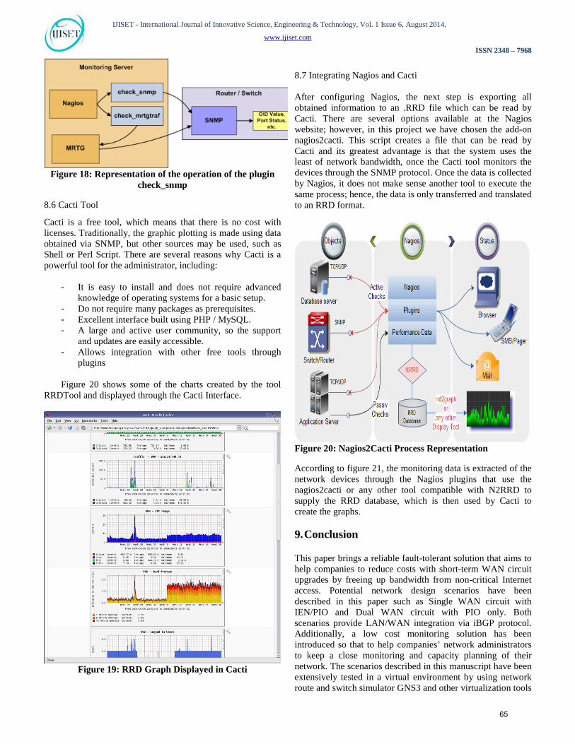
Figure 20 shows some of the charts created by the tool RRDTool and displayed through the Cacti Interface.
Figure 19: RRD Graph Displayed in Cacti
8.7 Integrating Nagios and Cacti After configuring Nagios, the next step is exporting all obtained information to an .RRD file which can be read by Cacti. There are several options available at the Nagios website; however, in this project we have chosen the add-on nagios2cacti. This script creates a file that can be read by Cacti and its greatest advantage is that the system uses the least of network bandwidth, once the Cacti tool monitors the devices through the SNMP protocol. Once the data is collected by Nagios, it does not make sense another tool to execute the same process; hence, the data is only transferred and translated to an RRD format.
Figure 20: Nagios2Cacti Process Representation
According to figure 21, the monitoring data is extracted of the network devices through the Nagios plugins that use the nagios2cacti or any other tool compatible with N2RRD to supply the RRD database, which is then used by Cacti to create the graphs. 9. Conclusion
This paper brings a reliable fault-tolerant solution that aims to help companies to reduce costs with short-term WAN circuit upgrades by freeing up bandwidth from non-critical Internet access. Potential network design scenarios have been described in this paper such as Single WAN circuit with IEN/PIO and Dual WAN circuit with PIO only. Both scenarios provide LAN/WAN integration via iBGP protocol. Additionally, a low cost monitoring solution has been introduced so that to help companies’ network administrators to keep a close monitoring and capacity planning of their network. The scenarios described in this manuscript have been extensively tested in a virtual environment by using network route and switch simulator GNS3 and other virtualization tools
65

IJISET - International Journal of Innovative Science, Engineering & Technology, Vol. 1 Issue 6, August 2014.
www.ijiset.com
ISSN 2348 – 7968
such as VMWare and Virtual Box, which have not been mentioned in this paper.
References [1] Multiprotocol Label Switching (MPLS), CISCO products (US),
http://www.cisco.com/en/US/products/ps6557/products_ios_technology_home.html
[2] Wendell Odom, CCNP Route 642-902, 1st ed., vol. 1. Cisco Press: Clarendon, 2010, pp.387–396.
[3] Generic Routing Encapsulation, “http://tools.ietf.org/pdf/rfc1701.pdf”
[4] Generic Routing Encapsulation over IPv4 networks. “http://tools.ietf.org/pdf/rfc1702.pdf”
[5] Updated Generic Routing Encapsulation (GRE), “http://tools.ietf.org/pdf/rfc2784.pdf”
[6] M. Watkins, CCNA Security Official Exam Certification Guide, Cisco Press, 2008.
[7] Zone Based Policy Firewall Design and Application Guide, “http://www.cisco.com/image/gif/paws/98628/zone-design-guide.pdf”
[8] Cisco Hot Standby Router Protocol (HSRP), “http://tools.ietf.org/pdf/rfc2281.pdf”
[9] Packet Flow Analysis in Wireless Scenario, http://www.ijarcsse.com/docs/papers/Volume_3/6_June2013/V3I6-0608.pdf
[10] Simple Network Management Protocol (SNMP), CISCO Networks, http://www.cisco.com/en/US/docs/internetworking/technology/handbook/SNMP.html.
[11] Nagios Monitoring Software Editions, Nagios http://www.nagios.org/download/core/
[12] W. Kocjan, Learning Nagios 3.0, Packt Publishing (pg. 8), 2008.
66


![A SURVEY ON WIRELESS SENSOR NETWORK PROTOCOLS …ijiset.com/v1s6/IJISET_V1_I6_91.pdf · 2014. 8. 30. · SPIN [5]SPIN (Sensor Protocols for Information via Negotiation) is a family](https://static.fdocuments.in/doc/165x107/61486cf52918e2056c22ae48/a-survey-on-wireless-sensor-network-protocols-2014-8-30-spin-5spin-sensor.jpg)