PRESTIGE - Triangle Tube · structions within this document and within the PRESTIGE Boiler...
48
This document is intended to be used by a qualified heating contractor or service technician. Read all in- structions within this document and within the PRESTIGE Boiler Installation and Maintenance Manual, before proceeding with the installation. It is recommended to follow the procedures in the steps given, skipping or missing procedural steps can result in substantial property damage, serious injury, or death. The installation must conform to the requirements of the authority having jurisdiction or, in the absence of such requirements, to the National Fuel Gas Code, ANSI Z223.1/ NFPA 54, and/or Natural Gas and Propane Installa- tion Code, CAN/CSA B149.1. NOTICE Revision date : 03/15/17 A1004331 - 664A0600 • A PVC, CPVC, PP & SS Vent Supplement PRESTIGE WARNING 2010-6 Prestige Vent Suppl.
Transcript of PRESTIGE - Triangle Tube · structions within this document and within the PRESTIGE Boiler...

This document is intended to be used by a qualified heating contractor or service technician. Read all in-structions within this document and within the PRESTIGE Boiler Installation and Maintenance Manual, before proceeding with the installation. It is recommended to follow the procedures in the steps given, skipping or missing procedural steps can result in substantial property damage, serious injury, or death.
The installation must conform to the requirements of the authority having jurisdiction or, in the absence of such requirements, to the National Fuel Gas Code, ANSI Z223.1/ NFPA 54, and/or Natural Gas and Propane Installa-
tion Code, CAN/CSA B149.1.
NOTICE
Revision date : 03/15/17 A1004331 - 664A0600 • A
PVC, CPVC, PP & SS Vent Supplement
PRESTIGE
WARNING
2010-6 Prestige Vent Suppl.
iiii
TABLE OF CONTENTS
CHAPTER 1 - PRE-INSTALLATION REQUIREMENTS ........................................................ 1
1.1. Removal of an Existing Boiler from a Common Vent System ............................................... 1
1.2. Vent/Combustion Air Piping and Materials ............................................................................2
1.2.1 PVC and CPVC Vent and Combustion Air Piping and Fittings ...........................................21.2.2 PVC and CPVC Pipe Cement and Primer ............................................................................21.2.3 AL29-4C® Stainless Steel Vent Piping and Fittings ..........................................................21.2.4 Polypropylene (PP) Vent Piping and Fittings ......................................................................3
1.3. Vent/Combustion Air Equivalent Lengths ..............................................................................9
1.4. Vent Restrictions .......................................................................................................................9
1.4.1 2 Inch (60 mm) Vent System Restrictions ..........................................................................91.4.2 3 Inch (80 mm) Vent System Restrictions .........................................................................91.4.3 Rigid Polypropylene Vent System Restrictions ................................................................ 101.4.4 Flex Polypropylene Vent System Restrictions .................................................................. 10
1.5. Combustion Air Contamination ..............................................................................................11
CHAPTER 2 - DIRECT VENT INSTALLATION OF VENT/AIR PIPING ............................. 13
2.1. Direct Vent - Vertical - Through the Roof or Unused Chimney ........................................... 13
2.1.1 Determine Termination Location ....................................................................................... 132.1.2 Direct Vent - Vent Installation - Through the Roof ............................................................ 142.1.3 Termination Fittings - Through the Roof ........................................................................... 152.1.4 Direct Vent - Multiple Boiler Installation - Through the Roof ........................................... 15
2.2. Direct Vent - Horizontal - Sidewall ......................................................................................... 17
2.2.1 Determine Termination Location ....................................................................................... 172.2.2 Direct Vent - Vent Installation - Sidewall ........................................................................... 182.2.3 Termination Fittings - Sidewall ........................................................................................... 182.2.4 Direct Vent - Multiple Boiler Installation - Sidewall .......................................................... 20
2.3. Direct Vent - Vertical Vent and Sidewall Combustion Air ....................................................22
2.3.1 Determine Termination Location .......................................................................................222.3.2 Direct Vent - Vent Installation - Through the Roof ............................................................232.3.3 Direct Vent - Combustion Air Installation - Sidewall ........................................................232.3.4 Termination Fittings - Vertical & Sidewall .........................................................................242.3.5 Direct Vent - Multiple Boiler Installation - Vertical Vent and Sidewall Combustion Air ........24

iiiiii
TABLE OF CONTENTS
CHAPTER 3 - CATEGORY IV (INDOOR AIR) INSTALLATION OF VENT/AIR PIPING ....25
3.1. Category IV - Vertical - Through the Roof or Unused Chimney ..........................................25
3.1.1 Determine Termination Location .......................................................................................253.1.2 Category IV - Vent Installation - Through the Roof .......................................................... 263.1.3 Termination Fittings - Through the Roof .......................................................................... 263.1.4 Category IV - Multiple Boiler Installation - Through the Roof ..........................................27
3.2. Category IV - Horizontal - Sidewall ........................................................................................27
3.2.1 Determine Termination Location .......................................................................................273.2.2 Category IV - Vent Installation - Sidewall ......................................................................... 293.2.3 Termination Fittings - Sidewall .......................................................................................... 293.2.4 Category IV - Multiple Boiler Installation - Sidewall ......................................................... 29
CHAPTER 4 - INSTALLATION REQUIREMENTS .............................................................. 31
4.1. Vent/Combustion Air Transitions .......................................................................................... 31
4.1.1 3” to 2” (60 mm) Transitions .............................................................................................. 314.1.2 3” to 4” (100 mm) Transitions ............................................................................................32
4.2. Connect Piping to PRESTIGE ..................................................................................................32
4.3. Vent and Combustion Air Piping Installation ....................................................................... 33
4.3.1 PVC/CPVC Vent System .................................................................................................... 334.3.2 Polypropylene or Stainless Steel Vent Systems .............................................................. 33
4.4. Carbon Monoxide Detector Installation ............................................................................... 34
CHAPTER 5 - MANIFOLD COMBUSTION AIR ..................................................................35
5.1. Manifold Combustion Air Option for Multiple Prestige Boilers ..........................................35
5.2. Combustion Air Manifold Equivalent Length ........................................................................35
5.3. Sidewall Termination ...............................................................................................................35
5.4. Installation Guidelines ............................................................................................................ 36
5.5. Transition Boiler Air Piping to Manifold Guidelines ............................................................ 36
CHAPTER 6 - COMMONWEALTH OF MASSACHUSETTS INSTALLATION REQUIREMENTS .................................................................................................................37
6.1. Installation of Carbon Monoxide Detectors. ........................................................................37
6.2. Approved Carbon Monoxide Detectors. ...............................................................................37
6.3. Signage .....................................................................................................................................37
6.4. Inspection. .............................................................................................................................. 38
6.4.1 Exemptions ........................................................................................................................ 386.4.2 Manufacturer Requirements - Gas Equipment Venting System Provided. .................. 386.4.3 Manufacturer Requirements - Gas Equipment Venting System Not Provided. ........... 38
iv
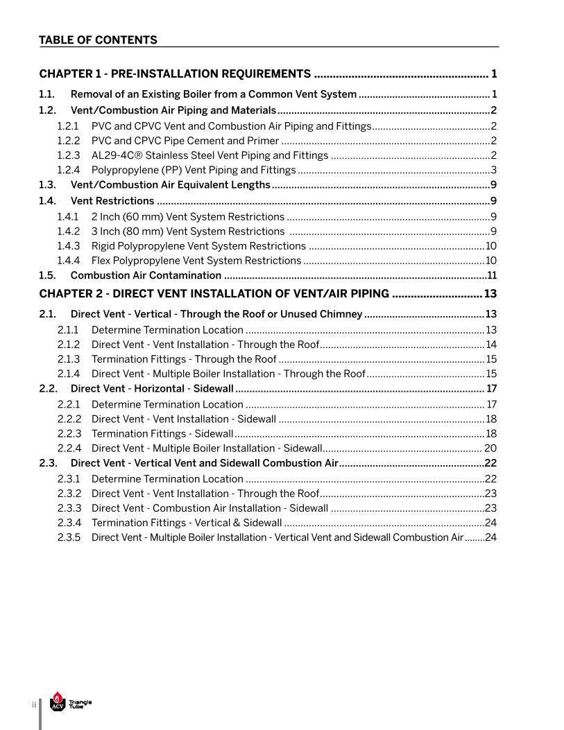
PRODUCT AND SAFETY INFORMATION
ACV-Triangle Tube reserves the right to modify the technical specifications and components of its products without prior notice. Check for an updated version of this manual at www.triangletube.com.
NOTICE
DEFINITIONS
The following terms are used throughout this manual to bring attention to the presence of potential hazards or to important information concerning the product.
Indicates the presence of a hazardous sit-uation which, if ignored, will result in sub-stantial property damage, serious injury, or
death.
Indicates a potentially hazardous situation which, if ignored, can result in substantial
property damage, serious injury, or death.
Indicates a potentially hazardous situation which, if ignored, can result in minor property
damage or injury.
Indicates special instructions on installation, oper-ation or maintenance, which are important to the equipment but not related to personal injury hazards.
Indicates recommendations made by ACV-Tri-angle Tube for the installers which will help to ensure optimum operation and longevity of the
equipment.
HOMEOWNER
• This manual is intended for use by a qualified heat-ing contractor or service technician.
• Please refer to the User Information manual for ad-ditional information.
• Ensure this document and all pertaining docu-ments are kept near the boiler to be used by the qualified heating contractor or service technician for future reference.
DANGER
WARNING
CAUTION
NOTICE
BEST PRACTICE
INSTALLER
Read all instructions as outlined in this man-ual and in the boiler installation manual. Failure to comply with these instructions in the order presented can result in substantial
property damage, serious injury, or death.
This document is a supplement to the PRESTIGE Boil-er Installation and Maintenance manual. The purpose of this supplement is to ensure the proper installation of the vent and combustion air piping to the boiler.
This vent supplement outlines Direct Vent and Category IV (Indoor Air) installations us-ing PVC, CPVC, PP and SS materials. For oth-er venting options (materials, terminations,
etc.), contact ACV-Triangle Tube.
• A byproduct of any gas fired appliance is carbon monoxide. ACV-Triangle Tube requires the installation of a minimum of two (2) hard-wired carbon monoxide detectors with an alarm and battery back-up; one in the mechanical room where the boiler is located and another installed in the living area outside the bedroom(s) for all installations. Consult the local authority having jurisdiction for any additional carbon monoxide detector requirements in your area. See Chapter 6 on page 37 for additional carbon monoxide detector
requirements in Massachusetts.
• All PRESTIGE vent and combustion air piping must be installed, terminated and joints sealed as outlined in this manual. Failure to comply with installa-tion procedures outlined in this manual can result in substantial property dam-
age, serious injury, or death.
WARNING
NOTICE
WARNING

1
CHA
PTER
1
CHAPTER 1 - PRE-INSTALLATION REQUIREMENTS
1.1. Removal of an Existing Boiler from a Common Vent System
Do not install the PRESTIGE into a common vent with any other gas or oil appliances. This will cause flue gas spillage or appliance malfunction, resulting in substantial proper-
ty damage, serious injury, or death.
When an existing boiler is removed from a common venting system, the common venting system is likely to be too large for proper venting of the remaining ap-pliances. At the time of removal of an existing boiler, the following steps shall be followed with each appli-ance remaining connected to the common venting system placed in operation, while the other appliances remaining connected to the common venting system are not in operation.
1. Seal any unused openings in the common venting system.
2. Visually inspect the venting system for proper size and horizontal pitch and determine there is no blockage or restriction, leakage, corrosion and oth-er deficiencies which could cause an unsafe con-dition.
3. Insofar as is practical close all building doors and windows and all doors between the space in which the appliances remaining connected to the com-mon venting system are located and other spac-es of the building. Turn on clothes dryers and any appliance not connected to the common venting system. Turn on any exhaust fans, such as range hoods and bathroom exhausts, so they will oper-ate at maximum speed. Do not operate a summer exhaust fan. Close fireplace dampers.
4. Place in operation the appliance being inspected. Follow the lighting instructions. Adjust thermostat so appliance will operate continuously.
5. Test for spillage at the draft hood relief opening after 5 minutes of main burner operation. Use the flame of a match or candle, or smoke from a ciga-rette, cigar or pipe.
6. After it has been determined that each appliance remaining connected to the common venting sys-tem properly vents when tested as outlined above, return doors, windows, exhaust fans, fireplace dampers and any other gas-burning appliance to their previous condition of use.
7. Any improper operation of the common venting system should be corrected so the installation conforms with the National Fuel Gas Code, ANSI Z223.1/NFPA 54 and/or CAN/CSA B149.1, Installa-tion Codes. When resizing any portion of the com-mon venting system, the common venting system should be resized to approach the minimum size as determined using the appropriate tables in Part 11 of the National Fuel Gas Code, ANSI Z223.1/NFPA 54 and/or CAN/CSA B149.1, Installation Codes.
DANGER

2
CHA
PTER 1
CHAPTER 1 - PRE-INSTALLATION REQUIREMENTS
1.2. Vent/Combustion Air Piping and Materials
The installation must conform to the require-ments of the authority having jurisdiction or, in the absence of such requirements, to the National Fuel Gas Code, ANSI Z223.1/ NFPA 54, and/or Natural Gas and Propane Installation
Code, CAN/CSA B149.1.
The Prestige is certified per ANSI Z21.13 as a Category IV (indoor air) or Direct Vent (sealed combustion) appliance. A Category IV appliance utilizes uncontaminated indoor or outdoor air (surrounding the appliance) for combus-tion. A Direct Vent appliance utilizes uncontaminated out-door air (piped directly to the appliance) for combustion.
To reduce the potential risks associated with indoor contaminates (listed on page 11), flam-mable vapors and tight housing construction (little or no infiltration air), it is recommended to pipe uncontaminated combustion air di-rectly from the outdoors to the appliance. This practice also promotes higher system efficien-cy by reducing heated indoor air from being exhausted from the building and replaced by
cold infiltration air.
The Prestige requires a Category IV venting system which is designed for pressurized venting and condensate.
The vent and combustion air materials (piping, fittings and cement) must meet the listed re-quirements in this manual. Failure to comply with these material requirements can result in substantial property damage, serious injury, or
death.
1.2.1 PVC and CPVC Vent and Combustion Air Piping and Fittings
• PVC Schedule 40 - ANSI/ASTM D1785• PVC-DWV - ANSI/ASTM D2665• CPVC Schedule 40 - ANSI/ASTM F441
NOTICE
BEST PRACTICE
WARNING
1.2.2 PVC and CPVC Pipe Cement and Primer
• PVC - ANSI/ASTM D2564• CPVC - ANSI/ASTM F493
• For installations in Canada, all piping, fit-tings and cement/primer material must be certified and listed to ULC-S636. Ipex Inc. is an approved manufacturer of ULC S636 vent
components.
• Use of cellular core PVC (ASTM F891) cel-lular core CPVC, or Radel® (polyphenol-sulfone) in venting systems is prohibited. Cellular core pipe may be used for combus-
tion air piping.
DO NOT mix a PVC/CPVC vent system & com-ponents with other vent system materials & components. Seal all PVC and CPVC pipe and fittings with the appropriate primer and ce-ment. Failure to comply with this requirement can cause the venting system to fail resulting in substantial property damage, serious injury,
or death.
1.2.3 AL29-4C® Stainless Steel Vent Piping and Fittings
Approved AL29-4C® Stainless Steel vent manufacturers and vent systems:
• SelKirk/Heatfab • Muelink and Grol B.V./Dura Vent• Z-FLEX U.S. Inc.
Only use approved stainless steel vent adapters and terminations listed in Table 1 on page 3.
Contact approved AL29-4C® stainless steel vent manufacturer for a copy of their instal-lation instructions. Read, understand and fol-low all of the vent manufacturer’s instructions before beginning the installation. Contact vent manufacturer if you require any tech-nical support. Failure to properly install and support vent system can cause the venting system to fail, resulting in substantial proper-
ty damage, serious injury, or death.
NOTICE
WARNING
WARNING

3
CHA
PTER
1
CHAPTER 1 - PRE-INSTALLATION REQUIREMENTS
• A specific vent adapter is required to transi-tion from the boiler vent outlet adapter to specific stainless steel vent system. Contact the appropriate AL29-4C® vent manufac-
turer for transition adapter information.• When using stainless steel for the vent sys-
tem, PVC or CPVC pipe meeting the listed requirements in this manual may be uti-
lized for the combustion air piping.
1.2.4 Polypropylene (PP) Vent Piping and Fittings
Approved polypropylene vent manufacturers and vent systems:
• Centrotherm Eco Systems, LLC• Muelink and Grol B.V./Dura Vent• Z-Flex U.S. Inc.• ECCO Manufacturing
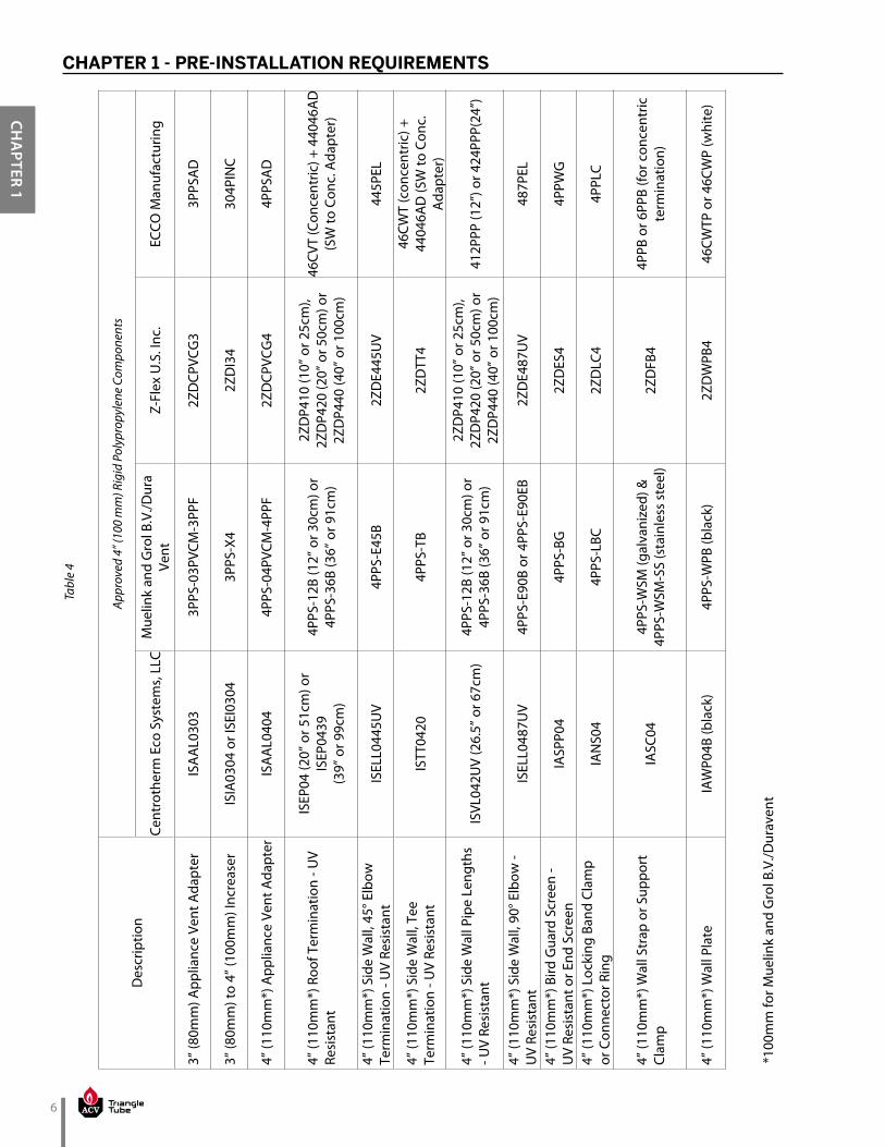
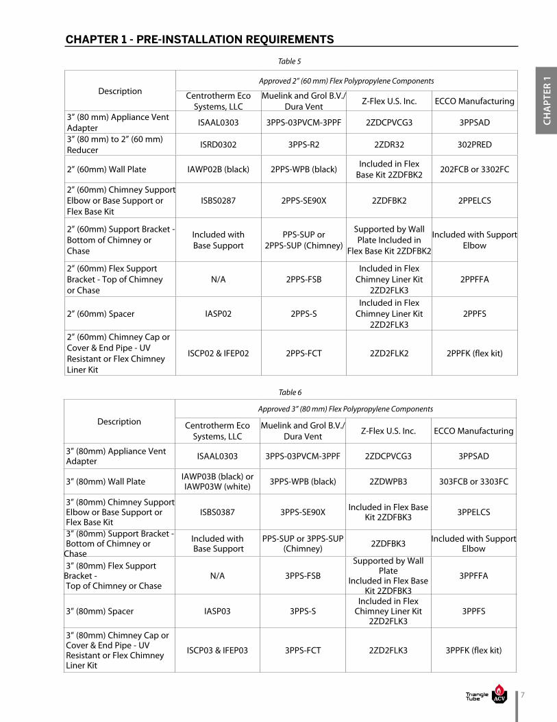
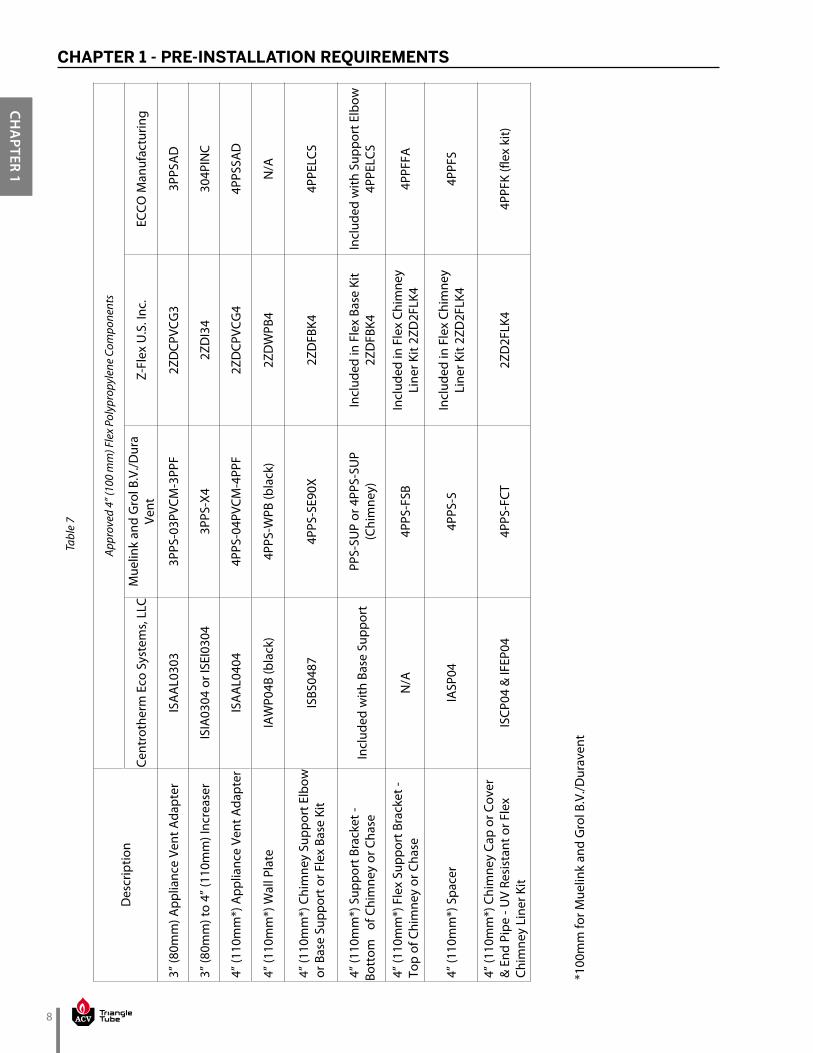
Only use approved polypropylene components listed in Table 2 on page 4 to Table 7 on page 8. Ter-mination must be selected from the options shown in this manual, using UV-resistant polypropylene.
NOTICEContact approved polypropylene vent man-ufacturer for a copy of their installation in-structions. Read, understand and follow all of the vent manufacturer’s instructions be-fore beginning the installation. Contact vent manufacturer if you require any technical support. Failure to properly install and sup-port vent system can cause the venting sys-tem to fail, resulting in substantial property
damage, serious injury, or death.
• A specific vent adapter may be required to transition from the boiler vent outlet adapter to the specific polypropylene vent system. Contact the appropriate PP vent manufacturer for transition adapter infor-
mation.
• When using Polypropylene for the vent sys-tem, PVC or CPVC pipe meeting the listed requirements in this manual may be utilized
for the combustion air piping.
WARNING
NOTICE
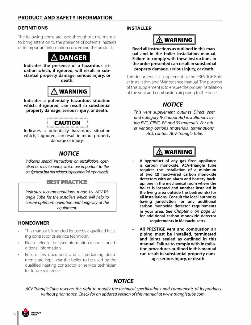
Table 1
Description
Approved Stainless Steel Vent Adapters and Terminations
SelKirk / Heatfab Saf-T Vent EZ Seal or
Saf-T Vent SC
M&G/DuraVent FasNSeal or CVS
Z-Flex U.S. Inc. Z-Vent
3” Vent Adapter 9301PVC FSA-ULT3 2SVSTTA03
3” Roof & Side Wall Straight Termination 9392 300186 2SVSTPF03
3” Side Wall & 45° Elbow Termination 9311TERM 300130 & 300186 2SVSTEX0345
3” Side Wall Tee Termination 9390TEE 300311 2SVSTTF03
3” to 4” Vent Adapter 9401PVC3 FSA-ULT3* 2SVSTTA04
4” Vent Adapter 9401PVC FSA-ULT4 SVSTTA04.5
4” Roof & Side Wall Straight Termination 9492 300187 2SVSTPF04
4” Side Wall & 45° Elbow Termination 9411TERM 300131 & 300187 2SVSTEX0445
4” Side Wall Tee Termination 9490TEE 300312 2SVSTTF04

4
CHA
PTER 1
CHAPTER 1 - PRE-INSTALLATION REQUIREMENTSTa
ble
2
Des
crip
tion
Appr
oved
2” (
60 m
m) R
igid
Pol
ypro
pyle
ne C
ompo
nent
s
Cent
roth
erm
Eco
Sys
tem
s, L
LCM
uelin
k an
d G
rol B
.V./D
ura
Vent
Z-Fl
ex U
.S. I
nc.
ECCO
Man
ufac
turin
g
3” (
80 m
m) A
pplia
nce
Vent
Ada
pter
IS
AA
L030
3 3P
PS-0
3PVC
M-3
PPF
2ZD
CPVC
G3
3PPS
AD
3” (
80 m
m) t
o 2”
(60
mm
) Red
ucer
IS
RD03
02
3PPS
-R2
2ZD
R32
302P
RED
2” (
60 m
m) R
oof T
erm
inat
ion
- UV
R
esis
tant
ISEP
02 (2
0” o
r 51c
m) o
r IS
EP02
39
(39”
or 9
9cm
)
2PPS
-12B
(12”
or 3
0cm
) or
2PPS
-36B
(3
6” o
r 91c
m)
2ZD
P210
UV
(10”
or 2
5cm
) or
2ZD
P220
UV
(20”
or 5
0 cm
)
24CV
T (C
once
ntric
) +
2202
4AD
(SW
to C
onc.
A
dapt
er)
2” (
60 m
m) S
ide
Wal
l, 45
° Elb
ow
Ter
min
atio
n - U
V Re
sist
ant
ISEL
L024
5UV
2PPS
-E45
B2Z
DE2
45U
V24
5PEL
B
2” (
60 m
m) S
ide
Wal
l, Te
e
Ter
min
atio
n - U
V Re
sist
ant
ISTT
0220
2P
PS-T
B2Z
DTT
22P
PWTK
(Tw
in P
ipe
Wal
l Kit)
2” (
60 m
m) S
ide
Wal
l Pip
e
Len
gths
- U
V Re
sist
ant
ISVL
022U
V (2
6.5”
or 6
7cm
) 2P
PS-1
2B (1
2” o
r 30c
m) o
r 2P
PS-3
6B
(36”
or 9
1cm
)
2ZD
P210
UV
(10”
or 2
5cm
) or
2ZD
P220
UV
(2
0” o
r 50
cm)
224P
PPB
(24”
) or 2
12PP
PB
(12”
)
2” (
60 m
m) S
ide
Wal
l, 90
° Elb
ow -
U
V Re
sist
ant
ISEL
L028
7UV
2PPS
-E90
B or
2PP
S-E9
0EB
2ZD
E287
UV
287P
ELB
2” (
60 m
m) B
ird G
uard
Scr
een
- UV
R
esis
tant
or E
nd S
cree
nIA
SPP0
2 2P
PS-B
G2Z
DES
22P
PWG
2” (
60 m
m) L
ocki
ng B
and
Clam
p or
C
onne
ctor
Rin
g IA
NS0
2 2P
PS-L
BC2Z
DLC
22P
PLC
2” (
60 m
m) W
all S
trap
or S
uppo
rt
Cla
mp
IASC
02
2PPS
-WSM
(gal
vani
zed)
&
2PPS
-WSM
-SS
(sta
inle
ss s
teel
)2Z
DFB
22P
PB o
r 24P
CB (f
or c
once
ntric
te
rmin
atio
n)
2” (
60m
m) W
all P
late
IA
WP0
2B (b
lack
) 22
” (60
mm
)PPS
-WPB
(bla
ck)
2ZD
WPB
224
CWTP
or 2
4CW
P (w
hite
)
5
CHA
PTER
1
CHAPTER 1 - PRE-INSTALLATION REQUIREMENTS
Tabl
e 3
Des
crip
tion
Appr
oved
3” (
80 m
m) R
igid
Pol
ypro
pyle
ne C
ompo
nent
s
Cent
roth
erm
Eco
Sys
tem
s, L
LCM
uelin
k an
d G
rol B
.V./D
ura
Vent
Z-Fl
ex U
.S. I
nc.
ECCO
Man
ufac
turin
g
3” (
80m
m) A
pplia
nce
Vent
Ada
pter
IS
AA
L030
3 3P
PS-0
3PVC
M-3
PPF
2ZD
CPVC
G3
3PPS
AD
3” (
80m
m) R
oof T
erm
inat
ion
- UV
R
esis
tant
ISEP
03 (2
0” o
r 51c
m) o
r IS
EP03
39
(39”
or 9
9cm
)
3PPS
-12B
(12”
or 3
0cm
) or
3PPS
-36B
(36”
or 9
1cm
)2Z
DP3
10U
V (1
0” o
r 25c
m) o
r 2Z
DP3
20U
V (2
0” o
r 50c
m)
35CV
T (C
once
ntric
) &
3303
5AD
(SW
to C
onc.
A
dapt
er)
3” (
80m
m) S
ide
Wal
l, 45
° Elb
ow
Ter
min
atio
n - U
V Re
sist
ant
ISEL
L034
5UV
3PPS
-E45
B2Z
DE3
45U
V34
5PEL
B
3” (
80m
m) S
ide
Wal
l, Te
e Te
rmin
atio
n -
UV
Resi
stan
t IS
TT03
20
3PPS
-TB
2ZD
TT3
3PPW
TK (T
win
Pip
e W
all K
it)
3” (
80m
m) S
ide
Wal
l Pip
e Le
ngth
s -
UV
Resi
stan
t IS
VL03
2UV
(26.
5” o
r 67c
m)
3PPS
-12B
(12”
or 3
0cm
) or
3PPS
-36B
(3
6” o
r 91c
m)
2ZD
P310
UV
(10”
or 2
5cm
) or
2ZD
P320
UV
(20”
or 5
0cm
)32
4PPP
B (2
4”) o
r 31
2PPP
B (1
2”)
3” (
80m
m) S
ide
Wal
l, 90
° Elb
ow -
UV
Resi
stan
t IS
ELL0
387U
V 3P
PS-E
90B
or 3
PPS-
E90E
B2Z
DE3
87U
V38
7PEL
B
3” (
80m
m) B
ird G
uard
Scr
een
- U
V Re
sist
ant o
r End
Scr
een
IASP
P03
3PPS
-BG
2ZD
ES3
3PPW
G
3” (
80m
m) L
ocki
ng B
and
Clam
p or
C
onne
ctor
Rin
g IA
NS0
3 3P
PS-L
BC2Z
DLC
33P
PLC
3” (
80m
m) W
all S
trap
or S
uppo
rt
Cla
mp
IASC
03
3PPS
-WSM
(gal
vani
zed)
&
3PP
S-W
SM-S
S (s
tain
less
ste
el)
2ZD
FB3
3PPB
or 5
PPB
(for c
once
ntric
te
rmin
atio
n)
3” (
80m
m) W
all P
late
IA
WP0
3B (b
lack
) or
IAW
P03W
(whi
te)
3PPS
-WPB
(bla
ck)
2ZD
WPB
335
CWTP
or 3
5CW
P (w
hite
)
6
CHA
PTER 1
CHAPTER 1 - PRE-INSTALLATION REQUIREMENTSTa
ble
4
Des
crip
tion
Appr
oved
4” (
100
mm
) Rig
id P
olyp
ropy
lene
Com
pone
nts
Cent
roth
erm
Eco
Sys
tem
s, L
LCM
uelin
k an
d G
rol B
.V./D
ura
Vent
Z-Fl
ex U
.S. I
nc.
ECCO
Man
ufac
turin
g
3” (
80m
m) A
pplia
nce
Vent
Ada
pter
IS
AA
L030
3 3P
PS-0
3PVC
M-3
PPF
2ZD
CPVC
G3
3PPS
AD
3” (
80m
m) t
o 4”
(100
mm
) Inc
reas
erIS
IA03
04 o
r ISE
I030
43P
PS-X
42Z
DI3
4 30
4PIN
C
4” (
110m
m*)
App
lianc
e Ve
nt A
dapt
er
ISA
AL0
404
4PPS
-04P
VCM
-4PP
F2Z
DCP
VCG
44P
PSA
D
4” (
110m
m*)
Roo
f Ter
min
atio
n - U
V
Res
ista
nt
ISEP
04 (2
0” o
r 51c
m) o
r IS
EP04
39
(39”
or 9
9cm
)
4PPS
-12B
(12”
or 3
0cm
) or
4PPS
-36B
(36”
or 9
1cm
)
2ZD
P410
(10”
or 2
5cm
),
2ZD
P420
(20”
or 5
0cm
) or
2ZD
P440
(40”
or 1
00cm
)
46CV
T (C
once
ntric
) + 4
4046
AD
(S
W to
Con
c. A
dapt
er)
4” (
110m
m*)
Sid
e W
all,
45° E
lbow
T
erm
inat
ion
- UV
Resi
stan
tIS
ELL0
445U
V4P
PS-E
45B
2ZD
E445
UV
445P
EL
4” (
110m
m*)
Sid
e W
all,
Tee
T
erm
inat
ion
- UV
Resi
stan
t IS
TT04
204P
PS-T
B2Z
DTT
446
CWT
(con
cent
ric) +
44
046A
D (S
W to
Con
c.
Ada
pter
)
4” (
110m
m*)
Sid
e W
all P
ipe
Leng
ths
- U
V Re
sist
ant
ISVL
042U
V (2
6.5”
or 6
7cm
)4P
PS-1
2B (1
2” o
r 30c
m) o
r 4P
PS-3
6B (3
6” o
r 91c
m)
2ZD
P410
(10”
or 2
5cm
),
2ZD
P420
(20”
or 5
0cm
) or
2ZD
P440
(40”
or 1
00cm
)41
2PPP
(12”
) or 4
24PP
P(24
”)
4” (
110m
m*)
Sid
e W
all,
90° E
lbow
- U
V Re
sist
ant
ISEL
L048
7UV
4PPS
-E90
B or
4PP
S-E9
0EB
2ZD
E487
UV
487P
EL
4” (
110m
m*)
Bird
Gua
rd S
cree
n -
UV
Resi
stan
t or E
nd S
cree
nIA
SPP0
44P
PS-B
G2Z
DES
44P
PWG
4” (
110m
m*)
Loc
king
Ban
d Cl
amp
or C
onne
ctor
Rin
g IA
NS0
44P
PS-L
BC2Z
DLC
44P
PLC
4” (
110m
m*)
Wal
l Str
ap o
r Sup
port
C
lam
p IA
SC04
4PPS
-WSM
(gal
vani
zed)
&
4PPS
-WSM
-SS
(sta
inle
ss s
teel
)2Z
DFB
44P
PB o
r 6PP
B (fo
r con
cent
ric
term
inat
ion)
4” (
110m
m*)
Wal
l Pla
te
IAW
P04B
(bla
ck)
4PPS
-WPB
(bla
ck)
2ZD
WPB
446
CWTP
or 4
6CW
P (w
hite
)
*100
mm
for M
uelin
k an
d G
rol B
.V./D
urav
ent
7
CHA
PTER
1
CHAPTER 1 - PRE-INSTALLATION REQUIREMENTS
DescriptionApproved 2” (60 mm) Flex Polypropylene Components
Centrotherm Eco Systems, LLC
Muelink and Grol B.V./Dura Vent Z-Flex U.S. Inc. ECCO Manufacturing
3” (80 mm) Appliance Vent Adapter ISAAL0303 3PPS-03PVCM-3PPF 2ZDCPVCG3 3PPSAD
3” (80 mm) to 2” (60 mm) Reducer ISRD0302 3PPS-R2 2ZDR32 302PRED
2” (60mm) Wall Plate IAWP02B (black) 2PPS-WPB (black) Included in Flex Base Kit 2ZDFBK2 202FCB or 3302FC
2” (60mm) Chimney Support Elbow or Base Support or Flex Base Kit
ISBS0287 2PPS-SE90X 2ZDFBK2 2PPELCS
2” (60mm) Support Bracket - Bottom of Chimney or Chase
Included with Base Support
PPS-SUP or 2PPS-SUP (Chimney)
Supported by Wall Plate Included in
Flex Base Kit 2ZDFBK2
Included with Support Elbow
2” (60mm) Flex Support Bracket - Top of Chimney or Chase
N/A 2PPS-FSBIncluded in Flex
Chimney Liner Kit 2ZD2FLK3
2PPFFA
2” (60mm) Spacer IASP02 2PPS-SIncluded in Flex
Chimney Liner Kit 2ZD2FLK3
2PPFS
2” (60mm) Chimney Cap or Cover & End Pipe - UV Resistant or Flex Chimney Liner Kit
ISCP02 & IFEP02 2PPS-FCT 2ZD2FLK2 2PPFK (flex kit)
Table 5
Table 6
DescriptionApproved 3” (80 mm) Flex Polypropylene Components
Centrotherm Eco Systems, LLC
Muelink and Grol B.V./Dura Vent Z-Flex U.S. Inc. ECCO Manufacturing
3” (80mm) Appliance Vent Adapter ISAAL0303 3PPS-03PVCM-3PPF 2ZDCPVCG3 3PPSAD
3” (80mm) Wall Plate IAWP03B (black) or IAWP03W (white) 3PPS-WPB (black) 2ZDWPB3 303FCB or 3303FC
3” (80mm) Chimney Support Elbow or Base Support or Flex Base Kit
ISBS0387 3PPS-SE90X Included in Flex Base Kit 2ZDFBK3 3PPELCS
3” (80mm) Support Bracket - Bottom of Chimney or Chase
Included with Base Support
PPS-SUP or 3PPS-SUP (Chimney) 2ZDFBK3 Included with Support
Elbow
3” (80mm) Flex Support Bracket - Top of Chimney or Chase
N/A 3PPS-FSB
Supported by Wall Plate
Included in Flex Base Kit 2ZDFBK3
3PPFFA
3” (80mm) Spacer IASP03 3PPS-SIncluded in Flex
Chimney Liner Kit 2ZD2FLK3
3PPFS
3” (80mm) Chimney Cap or Cover & End Pipe - UV Resistant or Flex Chimney Liner Kit
ISCP03 & IFEP03 3PPS-FCT 2ZD2FLK3 3PPFK (flex kit)
8
CHA
PTER 1
CHAPTER 1 - PRE-INSTALLATION REQUIREMENTS
Des
crip
tion
Appr
oved
4” (
100
mm
) Fle
x Po
lypr
opyl
ene
Com
pone
nts
Cent
roth
erm
Eco
Sys
tem
s, L
LCM
uelin
k an
d G
rol B
.V./D
ura
Vent
Z-Fl
ex U
.S. I
nc.
ECCO
Man
ufac
turin
g
3” (
80m
m) A
pplia
nce
Vent
Ada
pter
IS
AA
L030
3 3P
PS-0
3PVC
M-3
PPF
2ZD
CPVC
G3
3PPS
AD
3” (
80m
m) t
o 4”
(110
mm
) Inc
reas
erIS
IA03
04 o
r ISE
I030
43P
PS-X
42Z
DI3
4 30
4PIN
C
4” (
110m
m*)
App
lianc
e Ve
nt A
dapt
er
ISA
AL0
404
4PPS
-04P
VCM
-4PP
F2Z
DCP
VCG
44P
PSSA
D
4” (
110m
m*)
Wal
l Pla
te
IAW
P04B
(bla
ck)
4PPS
-WPB
(bla
ck)
2ZD
WPB
4N
/A
4” (
110m
m*)
Chi
mne
y Su
ppor
t Elb
ow
or B
ase
Supp
ort o
r Fle
x Ba
se K
itIS
BS04
87
4PPS
-SE9
0X2Z
DFB
K44P
PELC
S
4” (
110m
m*)
Sup
port
Bra
cket
- Bo
ttom
of
Chi
mne
y or
Cha
se
Incl
uded
with
Bas
e Su
ppor
t PP
S-SU
P or
4PP
S-SU
P (C
him
ney)
Incl
uded
in F
lex
Base
Kit
2ZD
FBK4
Incl
uded
with
Sup
port
Elb
ow
4PPE
LCS
4” (
110m
m*)
Fle
x Su
ppor
t Bra
cket
-
Top
of C
him
ney
or C
hase
N
/A
4PPS
-FSB
Incl
uded
in F
lex
Chim
ney
Line
r Kit
2ZD
2FLK
44P
PFFA
4” (
110m
m*)
Spa
cer
IASP
04
4PPS
-SIn
clud
ed in
Fle
x Ch
imne
y Li
ner K
it 2Z
D2F
LK4
4PPF
S
4” (
110m
m*)
Chi
mne
y Ca
p or
Cov
er
& E
nd P
ipe
- UV
Resi
stan
t or F
lex
C
him
ney
Line
r Kit
ISCP
04 &
IFEP
04
4PPS
-FCT
2ZD
2FLK
44P
PFK
(flex
kit)
Tabl
e 7
*100
mm
for M
uelin
k an
d G
rol B
.V./D
urav
ent
9
CHA
PTER
1
CHAPTER 1 - PRE-INSTALLATION REQUIREMENTS
1.3. Vent/Combustion Air Equivalent Lengths
• For all venting applications, PVC/CPVC, AL29-4C®, SS or Polypropylene, the length must not exceed the lengths listed in Table 8 below.
• For PVC/CPVC or AL29-4C® vent systems, reduce the maximum allowable length for each elbow as follows:
• 3 feet for every 45º elbow• 5 feet for every 90º elbow
• For polypropylene vent systems, reduce the maxi-mum allowable length for each elbow as follows:• 5 feet for every 45º elbow• 10 feet for every 90º elbow
1.4. Vent Restrictions
1.4.1 2 Inch (60 mm) Vent System Restrictions
• Derate the maximum boiler input by 3% when us-ing the maximum equivalent length of 2 inch (60 mm) vent piping on Solo 110 & Excellence.
• The 2 inch vent system requires a 1 inch clearance to combustibles.
• Use long sweep elbows to limit pressure drop and to avoid excessive vent temperatures.
• In 2 inch PVC vent applications, the first 7 equivalent feet of the vent system must utilize CPVC material.
To avoid vent failure, the installer must use CPVC vent material for the first 7 equivalent feet of a 2 inch PVC vent system. The installer must also utilize primer and glue that is cer-tified for both PVC/CPVC materials. Failure to comply with this requirement can cause the venting system to fail, resulting in substantial
property damage, serious injury, or death.
1.4.2 3 Inch (80 mm) Vent System Restrictions
Derate the maximum boiler input of the PRESTIGE Solo 250 by 3% when using the maximum equivalent length of 3 inch (80 mm) vent piping.
WARNING
Table 8
Prestige Model
Maximum Allowable Vent or Combustion Air Piping Length
2 Inch [60 mm] Piping
OR
3 Inch [80 mm] Piping
OR
4 Inch [100 mm] Piping
Feet Elbows Feet Elbows Feet Elbows
Solo 60 55 0 100 0 100 0
Solo 80 55 0 100 0 100 0
Solo 110 45 0 100 0 100 0
Solo 155
Not Applicable
100 0 100 0
Solo 175 100 0 100 0
Solo 250 60 0 80 0
Solo 299Not Applicable
100 0
Solo 399 100 0
Excellence 110 45 0 100 0 100 0

10
CHA
PTER 1
CHAPTER 1 - PRE-INSTALLATION REQUIREMENTS
1.4.4 Flex Polypropylene Vent System Restric-tions
• 2” Flex polypropylene venting is limited up to the PRESTIGE Solo 110 & Excellence.
• 3” Flex polypropylene venting is limited up to the PRESTIGE Solo 175.
Contact approved polypropylene vent man-ufacturer for a copy of their installation in-structions. Read, understand and follow all of the vent manufacturer’s instructions be-fore beginning the installation. Contact vent manufacturer if you require any technical support. Failure to properly install and sup-port vent system can cause the venting sys-tem to fail, resulting in substantial property
damage, serious injury, or death.• Approved for vertical installations only, where a
clean, structurally sound unused chimney or chase is used as a raceway.
• Vertical offsets must not exceed 45° and are limited to a maximum number of 2.
• Requires rigid polypropylene vent pipe with ap-proved locking band clamps or connector rings and wall straps or support clamps from the appli-ance to the entrance of the chimney or chase.
• Maintain 5/8” per foot slope back toward appliance on all horizontal runs of rigid polypropylene vent pipe.
• The use of a wall plate is required to seal rigid poly-propylene vent pipe at the entrance of the chim-ney or chase to prevent mortar or cement from contacting the polypropylene vent pipe.
• Requires supports (elbow or base, flex chimney and bracket), spacers, chimney cap and end pipe. Consult vent manufacturer for complete list of re-quired parts.
• Any termination piping external to the building must be UV resistant.
• Do not apply insulation directly to vent. Maintain vent manufacturers clearances to combustibles.
• Flex plastic venting systems shall not pass through rated fire separations.
• Prior to assembly of any joints, ensure joint gasket is present and properly installed. Contact vent manu-facturer if gasket is missing or damaged. Verify the in-tegrity of joints upon completion of the vent system.
WARNING
1.4.3 Rigid Polypropylene Vent System Restric-tions
Contact approved polypropylene vent man-ufacturer for a copy of their installation in-structions. Read, understand and follow all of the vent manufacturer’s instructions be-fore beginning the installation. Contact vent manufacturer if you require any technical support. Failure to properly install and sup-port vent system can cause the venting sys-tem to fail, resulting in substantial property
damage, serious injury, or death.
• Rigid polypropylene vent pipe must be installed with approved locking band clamps or connector rings and supports (wall strap or clamp, elbow or base, etc.). Consult vent manufacturer for com-plete list of required parts.
• Maintain 5/8” [1.5 cm] per foot slope back toward appliance on all horizontal runs.
• The use of a wall plate is required to seal rigid poly-propylene vent pipe at the entrance of the chim-ney or chase to prevent mortar or cement from contacting the polypropylene vent pipe.
• Any termination piping external to the building must be UV resistant.
• Do not apply insulation directly to vent. Maintain vent manufacturers clearances to combustibles.
• Plastic venting systems shall not pass through rat-ed fire separations without approved fire stopping installed in accordance with fire stopping manu-facturers instructions.
• Prior to assembly of any joints, ensure joint gasket is present and properly installed. Contact vent manu-facturer if gasket is missing or damaged. Verify the in-tegrity of joints upon completion of the vent system.
WARNING

11
CHA
PTER
1
CHAPTER 1 - PRE-INSTALLATION REQUIREMENTS
1.5. Combustion Air Contamination
If the PRESTIGE combustion air inlet is located in an area likely to cause or contain contamina-tion, or if products which could contaminate the air cannot be removed, the combustion air must be repiped and terminated at anoth-er location. Contaminated combustion air will damage the unit and its burner system, and can result in substantial property damage, se-
rious injury, or death.
• Do not operate the PRESTIGE if the com-bustion air inlet is located near a laundry room or pool facility. These areas will al-
ways contain hazardous contaminants.
• Pool, laundry, common household, and hobby products often contain fluorine or chlorine compounds. When these chem-icals pass through the burner and vent system, they can form strong acids. These acids will corrode the heat exchanger, burner components, and vent system, causing serious damage and possible flue gas spillage or water leakage into
the surrounding area.
• Please read the information listed on the right. If contaminating chemicals are lo-cated near the area of the combustion air inlet, the installer must pipe the com-bustion air inlet to an area free of these
chemicals.
• Failure to comply with these instructions will result in substantial property dam-
age, serious injury, or death
WARNING
DANGER
Potential contaminating products• Spray cans containing chloro/fluorocarbons• Permanent Wave Solutions• Chlorinated wax • Chlorine based swimming pool chemicals /
cleaners• Calcium Chloride used for thawing ice• Sodium Chloride used for water softening• Refrigerant leaks• Paint or varnish removers• Hydrochloric acid / muriatic acid• Cements and glues• Antistatic fabric softeners used in clothes dryers• Chlorine-type bleaches, detergents, and clean-
ing solvents found in household laundry rooms• Adhesives used to fasten building products and
other similar products
Areas likely to contain these products• Dry cleaning / laundry areas and establishments• Beauty salons• Metal fabrication shops• Swimming pools and health spas• Refrigeration Repair shops• Photo processing plants• Auto body shops• Plastic manufacturing plants• Furniture refinishing areas and establishments• New building construction• Remodeling areas• Garages with workshops

INTENTIONALLY LEFT BLANK

13
CHA
PTER
2
CHAPTER 2 - DIRECT VENT INSTALLATION OF VENT/AIR PIPING
A Direct Vent appliance utilizes uncontaminated outdoor air (piped directly to the appliance) for combustion.
2.1. Direct Vent - Vertical - Through the Roof or Unused Chimney
• The installation must conform to the re-quirements of the authority having jurisdic-tion or, in the absence of such requirements, to the National Fuel Gas Code, ANSI Z223.1/ NFPA 54, and/or Natural Gas and Propane
Installation Code, CAN/CSA B149.1.
• When using an inoperative chimney as a means of a chase for the vent, the surrounding space within the chimney cannot be used to draw combustion air or vent another appliance.
A gas vent extending through a roof must not terminate near an adjacent wall or below any building extensions such as roof eaves, balco-nies or decks. Failure to comply with the required clearances in this manual can result in substantial
property damage, serious injury, or death.
The information and diagrams outlining the fit-tings and method of terminating the vent/com-bustion air are directly related to PVC/CPVC vent systems. When utilizing an AL29-4C® or Polypro-pylene vent system, there may be some varia-tions. Consult the appropriate vent manufactur-
er for recommendations and clarifications.
2.1.1 Determine Termination Location
Locate the vent and combustion air termination using the following guidelines:
1. The total length of the vent or combustion air piping must not exceed the limits given in Table 8 on page 9.
Do not include the 90º elbows used to terminate the combustion air inlet exterior of the building
when determining the total length of pipe.
NOTICE
WARNING
NOTICE
NOTICE
2. The combustion air piping must terminate in an up-side down “U” shape fashion using two 90° elbows, as shown in Fig. 1 on page 14. The termination must be located 12” [30.5 cm] (18” [45.7 cm] Cana-da) above the highest anticipated snow level.
3. The vent piping must terminate vertically with a coupling to accept the bird screen and must be lo-cated 12” to 24” [30.5 cm to 61 cm] above the com-bustion air inlet as shown in Fig. 1 on page 14.
4. The vent and combustion air terminations must be located at a radial distance of 12” to 24” [30.5 cm to 61 cm] from centerline of vent termination to centerline of air termination as shown in Fig. 1 on page 14.
5. The following should be considered when deter-mining the location of the vent and combustion air terminations:a. Locate the vent termination where flue vapors
will not damage surrounding shrubs, plants, air conditioning equipment or be objectionable to the homeowner.
b. The flue products will form a noticeable plume of water vapor as they condense in colder air. Avoid terminating the vent in areas where the plume could obstruct window views.
c. Prevailing winds could cause freezing of flue gas condensation and a buildup of water / ice on surrounding plants, building surfaces or combustion air inlet.
d. Avoid locations where prevailing winds could affect the performance of the boiler or cause recirculation of the flue gases, such as inside corners of buildings, near adjacent buildings, vertical surfaces, window wells, stairwells, al-coves, courtyards, or other recessed areas.
e. Do not terminate the vent above doors or win-dows, flue condensate could freeze causing ice formations.
f. Locate the vent termination to prevent possible condensate damage to exterior finishes.
g. Avoid locations of possible accidental contact of flue vapors with people or pets.
6. The vent termination must also maintain the fol-lowing clearances, as shown in Fig. 2 on page 15:a. At least 3 feet [0.9 m] from adjacent wallsb. At least 3 feet [0.9 m] below roof overhangsc. At least 7 feet [2.1 m] above any public walkways

14
CHA
PTER 2
CHAPTER 2 - DIRECT VENT INSTALLATION OF VENT/AIR PIPING
12" Min. [30.5 cm]
Radial Distance
12" [30.5 cm] (18” [ 45.7 cm] Canada)
Above the HighestAnticipated Snow Level
Vent Termination
[30.
5 cm
to 6
1 cm
]12
" Min
. - 2
4" M
ax
Abov
e C
ombu
stio
n A
ir In
let
Combustion Air Termination
Fig. 1 - Direct Vent - Vertical Termination of Vent and Combustion Air Piping.
d. At least 3 feet [0.9 m] above any forced air in-take within 10 feet [3 m] (does not apply to the combustion air inlet of a direct vent appliance).
e. No closer than 12” [30.5 cm] below or horizontally from any door, window or gravity air inlet.
f. Must be at least 4 feet [1.2 m] from any elec-tric meters, gas meters-regulators, relief valves or other equipment. Never terminate the vent above or below any of these items within 4 feet [1.2 m] horizontally.
g. A minimum 12 inches [30.5 cm] horizontal spacing from other fan assisted appliance vents. Never ter-minate the vent above or below any fan assisted vent within 12 inches [30.5 cm] horizontally.
7. Locate the vent and combustion air terminations in a manner to protect from damage by foreign objects, such as stones, balls, or buildup of leaves or sediment.
8. Do not connect any other appliance to the vent pipe or multiple boilers to a common vent pipe.
2.1.2 Direct Vent - Vent Installation - Through the Roof
1. Vent and Combustion Air Penetration• Vent pipe penetration through combustible or
non-combustible wall material must maintain a minimum 1/4” [6 mm] clearance for 3” and 4” PVC/CPVC vent or 1” [2.5cm] for 2” PVC/CPVC vent. The diameter of the penetration hole must be 4” [10.2 cm] minimum for 2” and 3” pipe or 5” [12.7 cm] minimum for 4” pipe. When us-ing Polypropylene or Stainless Steel Vent refer to vent manufacturer’s Installation Instructions for clearances.
• Combustion air pipe penetration can maintain zero clearance. The diameter of the penetration hole should be 2-3/8” [6 cm] minimum for 2” pipe or 3-1/2” [8.9 cm] minimum for 3” pipe or 4-1/2” [11.4 cm] minimum for 4” pipe.
2. The installer must use a galvanized metal thimble for the vent pipe penetration.
3. Locate the vent and combustion air pipe penetrations to provide clearances as described in Fig. 1 on page 14.
4. The installer must comply with all local codes for isolating the vent and combustion air pipes as they pass through floors, ceilings and roofs.
5. The installer must provide adequate flashing and sealing boots sized for the vent pipe and combus-tion air pipe.

15
CHA
PTER
2
CHAPTER 2 - DIRECT VENT INSTALLATION OF VENT/AIR PIPING
Fig. 2 - Termination Clearances of Direct Vent System
2.1.3 Termination Fittings - Through the Roof
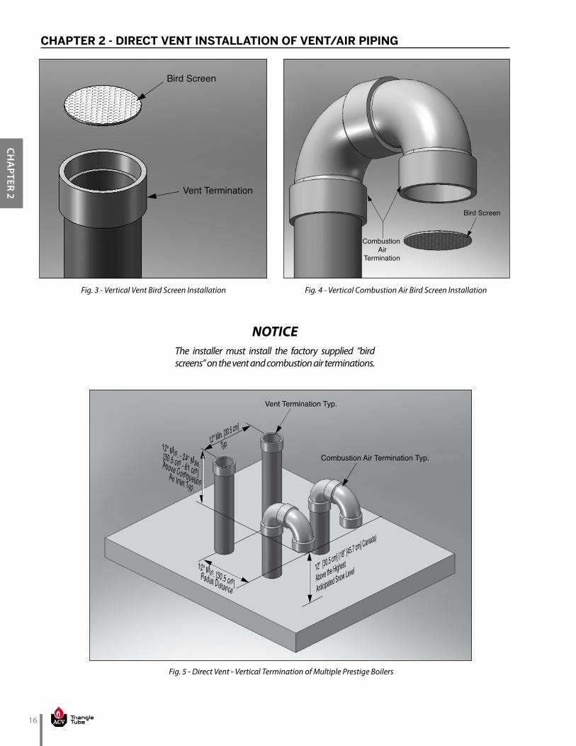
1. The vent and combustion air terminations must include a factory supplied “bird screen” installed as shown in Fig. 3 and Fig. 4 on page 16
2. The combustion air piping must terminate in an up-side down “U” shape fashion using two 90º elbows as shown in Fig. 1 on page 14.
3. The vent piping must terminate vertically with a coupling as shown in Fig. 1 on page 14.
Do not extend the vent pipe above the roof beyond the dimensions shown in Fig. 1 on page 14. Extended exposure of the vent pipe could cause condensate to freeze and block the vent pipe, resulting in substantial property dam-
age, serious injury, or death
WARNING
2.1.4 Direct Vent - Multiple Boiler Installation - Through the Roof
1. On installations of multiple PRESTIGE boilers, ter-minate each vent and combustion air pipe as de-scribed in this manual.
2. The roof penetration of the vent and combustion air piping must be such that the combustion air inlet is a minimum 12” [30.5 cm] from the adjacent vent pipe of the other boiler for installations in the U.S. as shown in Fig. 5 on page 16. For installations in Canada, provide clearances as required by CAN/CSA B149.1.
The combustion air inlet of the PRESTIGE is de-fined as being part of a direct vent system. It is not considered as a forced air intake. The re-quired clearance of an adjacent boiler vent to a forced air inlet does not apply in a multiple
installation of PRESTIGE boilers.
NOTICE
16
CHA
PTER 2
CHAPTER 2 - DIRECT VENT INSTALLATION OF VENT/AIR PIPING
Vent Termination
Bird Screen
The installer must install the factory supplied “bird screens” on the vent and combustion air terminations.
NOTICE
Combustion Air
Termination
Bird Screen
Vent Termination Typ.
Combustion Air Termination Typ.
12" [30.5 cm] (18” [45.7 cm] Canada)
Above the Highest
Anticipated Snow Level
12" Min. [30.5 cm]
Typ.
12" Min. [30.5 cm] Radial Distance
12" Min. - 24” Max.[30.5 cm - 61 cm] Above CombustionAir Inlet Typ.
Fig. 3 - Vertical Vent Bird Screen Installation Fig. 4 - Vertical Combustion Air Bird Screen Installation
Fig. 5 - Direct Vent - Vertical Termination of Multiple Prestige Boilers

17
CHA
PTER
2
CHAPTER 2 - DIRECT VENT INSTALLATION OF VENT/AIR PIPING
2.2. Direct Vent - Horizontal - Sidewall
• The installation must conform to the re-quirements of the authority having jurisdic-tion or, in the absence of such requirements, to the National Fuel Gas Code, ANSI Z223.1/ NFPA 54, and/or Natural Gas and Propane
Installation Code, CAN/CSA B149.1.• For sidewall vented installations in the Com-
monwealth of Massachusetts, the installer must comply with the additional require-
ments outlined in Chapter 6 on page 37.
A gas vent extending through a sidewall must not terminate near an adjacent wall or below any building extensions such as roof eaves, balconies or decks. Failure to comply with the required clearances in this manual can result in substantial property damage, serious injury, or
death.
The information and diagrams outlining the fittings and method of terminating the vent/combustion air are directly related to PVC/CPVC vent systems. When utilizing an AL29-4C® or Polypropylene vent system, there may be some variations. Consult the appropriate vent manufacturer for recommendations and clari-
fications.
2.2.1 Determine Termination Location
Locate the vent and combustion air termination using the following guidelines:
1. The total length of the vent or combustion air piping must not exceed the limits given in Table 8 on page 9.
Do not include the 90º elbows used to terminate the combustion air inlet and vent exterior of the building when determining the total length of pipe.
NOTICE
WARNING
NOTICE
NOTICE
2. The combustion air piping must terminate using a 90º elbow directed away from the vent termination. The termination must be located 12” [30.5 cm] mini-mum above grade / highest anticipated snow level as shown in Fig. 6 to Fig. 8 on page 19.
The combustion air termination can be placed on either side of the vent termination. The vent and combustion air terminations must be a minimum 12” [30.5 cm] apart horizontally and vertically. The vent and combustion air ter-minations are not required to be in the same pressure zone. The combustion air termination must be directed away from the vent for Fig. 8 on page 19. The combustion air termination must be directed down for Fig. 6 and Fig. 7 on
page 19.
3. The vent piping can terminate:• Using a 90º elbow as shown in Fig. 6 or Fig. 8 on
page 19.• Using a coupling as shown in Fig. 7 on page 19.• The vent termination must be located 12” [30.5
cm] minimum above the combustion air termi-nation.
4. The combustion air and vent pipe center lines must be a minimum of 12” [30.5 cm] apart as shown in Fig. 6 through Fig. 8 on page 19.
5. The following should be considered when determin-ing the location of the vent and combustion air termi-nations:a. Locate the vent termination where flue vapors
will not damage surrounding shrubs, plants, air conditioning equipment or be objectionable to the homeowner.
b. The flue products will form a noticeable plume of water vapor as they condense in colder air. Avoid terminating the vent in areas where the plume could obstruct window views.
c. Prevailing winds could cause freezing of flue gas condensation and a buildup of water / ice on sur-rounding plants, building surfaces or combustion air inlet.
NOTICE

18
CHA
PTER 2
CHAPTER 2 - DIRECT VENT INSTALLATION OF VENT/AIR PIPING
d. Avoid locations where prevailing winds could affect the performance of the boiler or cause recirculation of the flue gases, such as inside corners of buildings, near adjacent buildings, vertical surfaces, window wells, stairwells, al-coves, courtyards, or other recessed areas.
e. Do not terminate the vent above doors or win-dows, flue condensate could freeze causing ice formations.
f. Locate the vent termination to prevent possible condensate damage to exterior finishes.
g. Avoid locations of possible accidental contact of flue vapors with people or pets.
6. The vent termination must also maintain the fol-lowing clearances; as shown in Fig. 2 on page 15.a. At least 3 feet [0.9 m] from adjacent wallsb. At least 3 feet [0.9 m] below roof overhangsc. At least 7 feet [2.1 m] above any public walk-
waysd. At least 3 feet [0.9 m] above any forced air intake
within 10 feet [3 m] (does not apply to the com-bustion air inlet of a direct vent appliance).
e. No closer than 12” [30.5 cm] below or horizon-tally from any door, window or gravity air inlet.
f. Must be at least 4 feet [1.2 m] from any elec-tric meters, gas meters-regulators, relief valves or other equipment. Never terminate the vent above or below any of these items or within 4 feet [1.2 m] horizontally.
g. A minimum of 12” [30.5 cm] or a maximum of 24” [61 cm] beyond the exterior wall.
h. A minimum 12 inches [30.5 cm] horizontal spacing from other fan assisted appliance vents. Never terminate the vent above or below any fan assisted vent within 12 inches [30.5 cm] hor-izontally.
7. The edge of the combustion air termination cou-pling must extend 1” [2.5 cm] beyond the exterior wall as shown in Fig 6 through Fig. 8 on page 19.
8. Locate the vent and combustion air terminations in a manner to protect from damage by foreign objects, such as stones, balls, or buildup of leaves or sediment.
9. Do not connect any other appliance to the vent pipe or multiple boilers to a common vent pipe.
2.2.2 Direct Vent - Vent Installation - Sidewall1. Vent and Combustion Air Penetration
• Vent pipe penetration through combustible or non-combustible wall material must maintain a minimum 1/4” [6mm] clearance for 3” and 4” PVC/CPVC vent or 1” [2.5 cm] for 2” PVC/CPVC vent. The diameter of the penetration hole must be 4” [10.2 cm] minimum for 2” and 3” pipe or 5” [12.7 cm] minimum for 4” pipe. When using Polypropylene or Stainless Steel Vent refer to vent manufacturer’s Installation Instructions for clearances.
• Combustion air pipe penetration can maintain zero clearance. The diameter of the penetration hole should be 2-3/8” [6 cm] minimum for 2” pipe or 3-1/2” [8.9 cm] minimum for 3” pipe or 4-1/2” [11.4 cm] minimum for 4” pipe.
2. The installer must use a galvanized metal thimble for the vent pipe penetration.
3. Locate the vent and combustion air pipe penetra-tions to provide clearances as described in Fig. 6 through Fig. 8 on page 19.
4. The installer must comply with all local codes for iso-lating the vent and combustion air pipes as they pass through floors and walls.
5. The installer must seal all exterior openings around penetration with an exterior silicon caulk.
2.2.3 Termination Fittings - Sidewall1. The vent and combustion air terminations must in-
clude a factory supplied “bird screen” installed as shown in Fig. 9 and Fig. 10 on page 20.
2. The combustion air piping must terminate using a 90º elbow as shown in Fig. 6 through Fig. 8 on page 19.
3. The vent piping can terminate:• Using a 90º elbow as shown in Fig. 6 or Fig. 8 on
page 19.• Using a coupling as shown in Fig. 7 on page 19.
The vent termination must be installed 12” [30.5 cm] minimum above the combustion air termination.
Do not extend the vent pipe outside the side-wall beyond the dimensions shown in Fig. 6 through Fig. 8 on page 19. Extended expo-sure of the vent pipe could cause condensate to freeze and block the vent pipe, resulting in substantial property damage, serious injury,
or death.
WARNING

19
CHA
PTER
2
CHAPTER 2 - DIRECT VENT INSTALLATION OF VENT/AIR PIPING
12” Min. - 24” Max. [ 30.5 cm - 61 cm]From Wall To Vent
12" [
30.5
cm
] Min
. Ab
ove
Gra
de /
Hig
hest
Ant
icip
ated
Sno
w L
evel
12" Max.
[30.5 cm]
12" Min.
[30.5 cm]
12" Min. 24" Max.
[30.5 cm - 61 cm]
1" [2.5 cm] From Wall To Edge of Coupling - Air
Combustion AirTermination
Vent Termination
Combustion AirTermination
12" M
in. -
24"
Max
[3
04.8
mm
- 60
9.6
mm
] Ab
ove
Com
bust
ion
Air
Inle
t
12" Min. - 24” Max.[30.5 - 61 cm] From Wall to Vent
1" [2.5 cm] From Wall To Edge of Coupling - Air
12" [30.5 cm] Min.
Above Grade / Highest
Anticipated Snow Level
12" Min.
[30.5 cm] Typ.
12"
Min
- 24
” Max
.[3
0.5
cm -
61 c
m]
Vent Termination
Combustion AirTermination
Combustion AirTermination
12" Min.[30.5 cm]
Horizontally
from Vent to Air
1" [2.5 cm] From Wall To Edge of Coupling - Air
12” Min. - 24” Max. [ 30.5 cm - 61 cm] From Wall To Vent
12" Min.
[30.5 cm]
12" Min. [30.5 cm ]
Above Grade/Highest
Anticipated Snow Level
Fig. 6 - Direct Vent - Sidewall Termination of Vent and Combustion Air Piping
Fig. 7 - Direct Vent - Alternate Sidewall Termination of Vent and Combustion Air Piping
Fig. 8 - Direct Vent - Sidewall Snorkel Termination of Vent and Combus-tion Air Piping
20
CHA
PTER 2
CHAPTER 2 - DIRECT VENT INSTALLATION OF VENT/AIR PIPING
Vent Termination
Bird Screen
Combustion Air Termination
Bird Screen
The installer must install the factory-supplied “bird screens” on the vent and combustion air
terminations.
NOTICE
Fig. 9 - Sidewall Vent Bird Screen Installation Fig. 10 - Sidewall Combustion Air Bird Screen Installation
2.2.4 Direct Vent - Multiple Boiler Installation - Sidewall
1. On installations of multiple PRESTIGE boilers, ter-minate each vent and combustion air pipe as de-scribed in this manual.
2. The wall penetration of the vent and combustion air piping must be such that the combustion air in-let is a minimum 12” [30.5 cm] from the adjacent vent pipe of the other boiler for installations in the U.S as shown in Fig. 11 on page 21. For installa-tions in Canada, provide clearances as required by CAN/CSA B149.1.
The combustion air inlet of the PRESTIGE is de-fined as being part of a direct vent system. It is not considered as a forced air intake. The re-quired clearance of an adjacent boiler vent to a forced air inlet does not apply in a multiple
installation of PRESTIGE boilers.
NOTICE
• Fig. 11 on page 21 shows one option for vent and combustion air terminations of multiple PRESTIGE boilers. Either termi-nation option shown in Fig 6 or Fig. 7 on page 19 can be used for multiple PRES-TIGE boilers. The 12” [30.5 cm] minimum distance between centerlines of the com-bustion air and vent piping must be main-
tained for any chosen option.
• Refer to Fig. 6 or Fig. 7 on page 19 for the vent and combustion air inlet termination dimensions for each unit installed in a mul-
tiple installation.
NOTICE

21
CHA
PTER
2
CHAPTER 2 - DIRECT VENT INSTALLATION OF VENT/AIR PIPING
Combustion AirTerminations
Vent Terminations
24" [ 61 cm] Max. 12" [30.5 cm] Min.
12” Min. - 24” Max. [ 30.5 cm - 61 cm]From Wall To VentTyp.
1" [2.5 cm] From Wall To Edge of Coupling - AirTyp.
12" Min. [30.5 cm]
Horizontally Between
All Terminations
12" [30.5 cm]
Min. Above
Grade/Highest
Anticipated
Snow Level, Typ.
Fig. 11 - Direct Vent - Sidewall Termination of Multiple Prestige Boilers
1" Min. [2.5 cm] From Wall To Edge of Coupling-Air
36" Max.[91.4 cm]
12"
[30.
5 cm
] Min
. Ab
ove
Gra
de /
Hig
hest
Ant
icip
ated
Sno
w L
evel
12" [30.5 cm] (18” [45.7 cm] Canada)
Above the HighestAnticipated Snow Level
Combustion Air Termination
Vent Termination
Fig. 12 - Direct Vent - Vertical Vent and Side Wall Combustion Air Terminations
22
CHA
PTER 2
CHAPTER 2 - DIRECT VENT INSTALLATION OF VENT/AIR PIPING
2.3. Direct Vent - Vertical Vent and Sidewall Combustion Air
• The installation must conform to the re-quirements of the authority having juris-diction or, in the absence of such require-ments, to the National Fuel Gas Code, ANSI Z223.1/ NFPA 54, and/or Natural Gas and Propane Installation Code, CAN/CSA
B149.1.• When using an inoperative chimney as
a means of a chase for the vent, the sur-rounding space within the chimney cannot be used to draw combustion air or vent an-
other appliance.
A gas vent extending through a roof must not terminate near an adjacent wall or below any building extensions such as roof eaves, bal-conies or decks. Failure to comply with the re-quired clearances in this manual can result in substantial property damage, serious injury, or
death.
The information and diagrams outlining the fittings and method of terminating the vent/combustion air are directly related to PVC/CPVC vent systems. When utilizing an AL29-4C® or Polypropylene vent system, there may be some variations. Consult the appropriate vent manufacturer for recommendations and clari-
fications.
NOTICE
WARNING
NOTICE
2.3.1 Determine Termination Location
Locate the vent and combustion air termination using the following guidelines:
1. The total length of the vent or combustion air pip-ing must not exceed the limits given in Table 8 on page 9.
Do not include the 90º elbows used to terminate the combustion air inlet exterior of the building
when determining the total length of pipe.
2. The combustion air piping must terminate with a 90º elbow. Fig. 12 on page 21 shows a snorkel termination option. The combustion air pipe can also terminate using a 90º elbow directed down as shown in Fig. 6 on page 19. The termination must be located 12” [30.5 cm] minimum above grade / highest anticipated snow level.
3. The vent piping must terminate vertically with a coupling to accept the bird screen and must be located 12” [30.5 cm] (18” [45.7 cm] Canada) above the highest anticipated snow level.
4. The following should be considered when deter-mining the location of the vent and combustion air terminations:a. Locate the vent termination where flue vapors
will not damage surrounding shrubs, plants, air conditioning equipment or be objectionable to the homeowner.
b. The flue products will form a noticeable plume of water vapor as they condense in colder air. Avoid terminating the vent in areas where the plume could obstruct window views.
c. Prevailing winds could cause freezing of flue gas condensation and a buildup of water / ice on surrounding plants, building surfaces or combustion air inlet.
d. Avoid locations where prevailing winds could affect the performance of the boiler or cause recirculation of the flue gases, such as inside corners of buildings, near adjacent buildings, vertical surfaces, window wells, stairwells, al-coves, courtyards, or other recessed areas.
NOTICE

23
CHA
PTER
2
CHAPTER 2 - DIRECT VENT INSTALLATION OF VENT/AIR PIPING
e. Do not terminate the vent above doors or win-dows, flue condensate could freeze causing ice formations.
f. Locate the vent termination to prevent possible condensate damage to exterior finishes.
g. Avoid locations of possible accidental contact of flue vapors with people or pets.
5. The vent termination must also maintain the fol-lowing clearances; as shown in Fig. 2 on page 15.a. At least 3 feet [0.9 m] from adjacent wallsb. At least 3 feet [0.9 m] below roof overhangsc. At least 7 feet [2.1 m] above any public walk-
waysd. At least 3 feet [0.9 m] above any forced air in-
take within 10 feet [3 m] (does not apply to the combustion air inlet of a direct vent appliance).
e. No closer than 12” [30.5 cm] below or horizon-tally from any door or window or gravity air inlet.
f. Must be at least 4 feet [1.2 m] from any elec-tric meters, gas meters-regulators, relief valves or other equipment. Never terminate the vent above or below any of these items within 4 feet [1.2 m] horizontally.
g. A minimum 12 inches [30.5 cm] horizontal spacing from other fan assisted appliance vents. Never ter-minate the vent above or below any fan assisted vent within 12 inches [30.5 cm] horizontally.
6. The edge of the combustion air termination cou-pling must extend 1” [2.5 cm] beyond the exterior wall as shown in Fig. 12 on page 21.
7. Locate the vent and combustion air terminations in a manner to protect from damage by foreign objects, such as stones, balls, or buildup of leaves or sediment.
8. Do not connect any other appliance to the vent pipe or multiple boilers to a common vent pipe.
2.3.2 Direct Vent - Vent Installation - Through the Roof
1. Vent pipe penetration through combustible or non-combustible wall material must maintain a minimum 1/4” [6 mm] clearance for 3” and 4” PVC/CPVC vent or 1” [2.5 cm] for 2” PVC/CPVC vent. The diameter of the penetration hole must be 4” [10.2 cm] minimum for 2” and 3” pipe or 5” [12.7 cm] minimum for 4” pipe. When using Polypropylene or Stainless Steel Vent refer to vent manufacturer’s Installation Instructions for clearances.
2. The installer must use a galvanized metal thimble for the vent pipe penetration.
3. The vent must terminate 12” [30.5 cm] (18” [45.7 cm] Canada) above the highest anticipated snow level.
4. The installer must comply with all local codes for isolating the vent pipe as it passes through floors, ceilings and roofs.
5. The installer must provide adequate flashing and sealing boots sized for the vent pipe.
2.3.3 Direct Vent - Combustion Air Installation - Sidewall
1. Combustion air pipe penetration can maintain zero clearance. The diameter of the penetration hole should be 2 3/8” [6 cm] minimum for 2” pipe or 3 1/2” [8.9 cm] minimum for 3” pipe or 4 1/2” [11.4 cm] minimum for 4” pipe.
2. The combustion air termination must be installed 12” [30.5 cm] minimum above grade / highest an-ticipated snow level as shown in Fig. 6 or Fig. 8 on page 19.
3. The installer must comply with all local codes for isolating the combustion air pipe as it passes through floors and walls.
4. The installer must seal all exterior openings around penetration with an exterior silicon caulk.

24
CHA
PTER 2
CHAPTER 2 - DIRECT VENT INSTALLATION OF VENT/AIR PIPING
12" Min.
[30.5 cm]
36" Max. [91.4 cm]
12" Min.
[30.5 cm]
12" [
30.5
cm] M
in. Ab
ove G
rade /
High
est
Antici
pated
Snow
Leve
l
12" [30.5 cm] (18” [45.7 cm] Canada) Above Highest Anticipated Snow Level Typ.
1" [2.5 cm]From Wall toEdge of
Coupling-Air
Combustion Air Terminations
Vent Terminations
Fig. 13 - Direct Vent - Vertical Vent and Sidewall Combustion Air Terminations of Multiple Pres-tige Boilers
2.3.4 Termination Fittings - Vertical & Sidewall
1. The vent and combustion air terminations must include a factory supplied “bird screen” installed as shown in Fig. 3 on page 16 & Fig. 10 on page 20.
2. The combustion air piping must terminate using a 90º elbow as shown in Fig. 6 or Fig. 8 on page 19.
3. The vent piping must terminate vertically with a coupling, as shown in Fig. 12 on page 21.
Do not extend the vent pipe above the roof beyond the dimension shown in Fig. 12 on page 21. Extended exposure of the vent pipe could cause condensate to freeze and block the vent pipe, resulting in substantial
property damage, serious injury, or death.
WARNING
2.3.5 Direct Vent - Multiple Boiler Installation - Vertical Vent and Sidewall Combustion Air
1. On installations of multiple PRESTIGE boilers, ter-minate each vent and combustion air pipe as de-scribed in this manual.
2. Each vent and combustion air termination must be a minimum 12” [30.5 cm] from the adjacent termi-nation for installations in the U.S. as shown in Fig. 13. For installations in Canada, provide clearances as required by CAN/CSA B149.1.
The combustion air inlet of the PRESTIGE is de-fined as being part of a direct vent system. It is not considered as a forced air intake. The re-quired clearance of an adjacent boiler vent to a forced air inlet does not apply in a multiple
installation of PRESTIGE boilers.
NOTICE

25
CHA
PTER
3
CHAPTER 3 - CATEGORY IV (INDOOR AIR) INSTALLATION OF VENT/AIR PIPING
A Category IV appliance utilizes uncontaminated indoor or outdoor air (surrounding the appliance) for combus-tion.
3.1. Category IV - Vertical - Through the Roof or Unused Chimney
• The installation must conform to the re-quirements of the authority having juris-diction or, in the absence of such require-ments, to the National Fuel Gas Code, ANSI Z223.1/ NFPA 54, and/or Natural Gas and Propane Installation Code, CAN/CSA
B149.1.
• When using an inoperative chimney as a means of a chase for the vent, the surround-ing space within the chimney cannot be used to draw combustion air or vent another appli-
ance.
A gas vent extending through a roof must not terminate near an adjacent wall or below any building extensions such as roof eaves, bal-conies or decks. Failure to comply with the re-quired clearances in this manual can result in substantial property damage, serious injury, or
death.
The information and diagrams outlining the fittings and method of terminating the vent/combustion air are directly related to PVC/CPVC vent systems. When utilizing an AL 29-4C® or Polypropylene vent system, there may be some variations. Consult the appropriate vent manufacturer for recommendations and
clarifications.
NOTICE
WARNING
NOTICE
3.1.1 Determine Termination Location
Locate the vent and combustion air termination using the following guidelines:
1. The total length of the vent piping must not exceed the limits given in Table 8 on page 9.
2. The combustion air piping must terminate at the boiler with a 90º elbow.
3. The vent piping must terminate vertically with a coupling to accept the bird screen and must be located 12” [30.5 cm] (18” [45.7 cm] Canada) above the highest anticipated snow level as shown in Fig. 14 on page 25
4. The following should be considered when deter-mining the location of the vent termination:a. Locate the vent termination where flue vapors
will not damage surrounding shrubs, plants, air conditioning equipment or be objectionable to the homeowner.
b. The flue products will form a noticeable plume of water vapor as they condense in colder air. Avoid terminating the vent in areas where the plume could obstruct window views.
c. Prevailing winds could cause freezing of flue gas condensation and a buildup of water / ice on surrounding plants or building surfaces.
d. Avoid locations where prevailing winds could affect the performance of the boiler or cause recirculation of the flue gases, such as inside corners of buildings, near adjacent buildings, vertical surfaces, window wells, stairwells, al-coves, courtyards, or other recessed areas.
Vent Termination
12" [30.5 cm] (18” [45.7 cm] Canada)
Above the HighestAnticipated Snow Level
Fig. 14 - Category - IV - Vertical Termination of Vent Pipe

26
CHA
PTER 3
CHAPTER 3 - CATEGORY IV (INDOOR AIR) INSTALLATION OF VENT/AIR PIPING
e. Do not terminate the vent above doors or win-dows, flue condensate could freeze causing ice formations.
f. Locate the vent termination to prevent possible condensate damage to exterior finishes.
g. Avoid locations of possible accidental contact of flue vapors with people or pets.
5. The vent termination must also maintain the fol-lowing clearances; as shown in Fig. 15 below.a. At least 3 feet [0.9 m] from adjacent wallsb. At least 3 feet [0.9 m] below roof overhangsc. At least 7 feet [2.1 m] above any public walk-
waysd. At least 3 feet [0.9 m] above any forced air in-
take within 10 feet [3 m] (Does not apply to the combustion air inlet of a direct vent appliance).
e. No closer than 4 feet [1.2 m] below or horizon-tally from any door, window or gravity air inlet.
f. Must be at least 4 feet [1.2 m] from any elec-tric meters, gas meters-regulators, relief valves or other equipment. Never terminate the vent above or below any of these items within 4 feet [1.2 m] horizontally.
g. A minimum 12 inches [30.5 cm] horizontal spac-ing from other fan assisted appliance vents. Never terminate the vent above or below any fan assist-ed vent within 12 inches [30.5 cm] horizontally.
6. Locate the vent termination in a manner to protect from damage by foreign objects, such as stones, balls, or buildup of leaves or sediment.
7. Do not connect any other appliance to the vent pipe or multiple boilers to a common vent pipe.
3.1.2 Category IV - Vent Installation - Through the Roof
1. Vent pipe penetration through combustible or non-combustible wall material must maintain a minimum 1/4” [6 mm] clearance for 3” and 4” PVC/CPVC vent or 1” [2.5 cm] for 2” PVC/CPVC vent. The di-ameter of the penetration hole must be 4” [10.2 cm] minimum for 2” and 3” pipe or 5” [12.7 cm] minimum for 4” pipe. When using Polypropylene or Stainless Steel Vent refer to vent manufacturer’s Installation Instructions for clearances.
2. The installer must use a galvanized metal thimble for the vent pipe penetration.
3. Locate the vent pipe penetration to provide clear-ances as described in Fig. 14 on page 25.
4. The installer must comply with all local codes for isolating the vent pipe as it passes through floors, ceilings and roofs.
5. The installer must provide adequate flashing and a sealing boot sized for the vent pipe.
3.1.3 Termination Fittings - Through the Roof
1. The vent and combustion air terminations must include a factory supplied “bird screen” installed as shown in Fig. 3 and Fig. 4 on page 16.
2. The combustion air piping must terminate at the boiler with a 90º elbow.
3. The vent piping must terminate vertically with a coupling as shown in Fig. 14 on page 25.
Do not extend the vent pipe above the roof beyond the dimensions shown in Fig. 14 on page 25. Extended exposure of the vent pipe could cause condensate to freeze and block the vent pipe, resulting in substantial
property damage, serious injury, or death.
WARNING
Fig. 15 - Termination Clearances of Category IV System
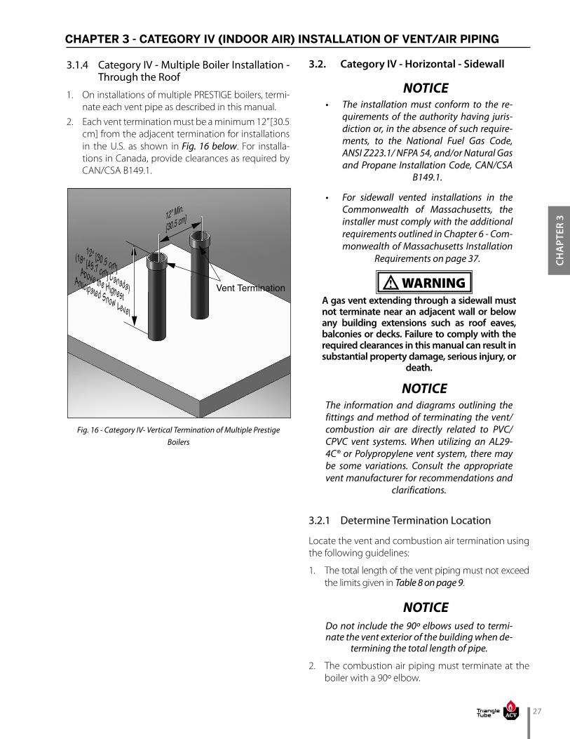
27
CHA
PTER
3
3.1.4 Category IV - Multiple Boiler Installation - Through the Roof
1. On installations of multiple PRESTIGE boilers, termi-nate each vent pipe as described in this manual.
2. Each vent termination must be a minimum 12” [30.5 cm] from the adjacent termination for installations in the U.S. as shown in Fig. 16 below. For installa-tions in Canada, provide clearances as required by CAN/CSA B149.1.
3.2. Category IV - Horizontal - Sidewall
• The installation must conform to the re-quirements of the authority having juris-diction or, in the absence of such require-ments, to the National Fuel Gas Code, ANSI Z223.1/ NFPA 54, and/or Natural Gas and Propane Installation Code, CAN/CSA
B149.1.
• For sidewall vented installations in the Commonwealth of Massachusetts, the installer must comply with the additional requirements outlined in Chapter 6 - Com-monwealth of Massachusetts Installation
Requirements on page 37.
A gas vent extending through a sidewall must not terminate near an adjacent wall or below any building extensions such as roof eaves, balconies or decks. Failure to comply with the required clearances in this manual can result in substantial property damage, serious injury, or
death.
The information and diagrams outlining the fittings and method of terminating the vent/combustion air are directly related to PVC/CPVC vent systems. When utilizing an AL29-4C® or Polypropylene vent system, there may be some variations. Consult the appropriate vent manufacturer for recommendations and
clarifications.
3.2.1 Determine Termination Location
Locate the vent and combustion air termination using the following guidelines:
1. The total length of the vent piping must not exceed the limits given in Table 8 on page 9.
Do not include the 90º elbows used to termi-nate the vent exterior of the building when de-
termining the total length of pipe.
2. The combustion air piping must terminate at the boiler with a 90º elbow.
NOTICE
WARNING
NOTICE
NOTICE
Vent Termination
12" [30.5 cm] (18” [45.7 cm] Canada)
Above the HighestAnticipated Snow Level
12" Min.
[30.5 cm]
Fig. 16 - Category IV- Vertical Termination of Multiple Prestige Boilers
CHAPTER 3 - CATEGORY IV (INDOOR AIR) INSTALLATION OF VENT/AIR PIPING

28
CHA
PTER 3
3. The vent piping can terminate:• Using a coupling as shown in Fig. 17.• Using a 90º elbow as shown in Fig. 18.• The vent termination must be located 12” [30.5
cm] minimum above grade / highest anticipat-ed snow level.
4. The following should be considered when deter-mining the location of the vent termination:a. Locate the vent termination where flue vapors
will not damage surrounding shrubs, plants, air conditioning equipment or be objectionable to the homeowner.
b. The flue products will form a noticeable plume of water vapor as they condense in colder air. Avoid terminating the vent in areas where the plume could obstruct window views.
c. Prevailing winds could cause freezing of flue gas condensation and a buildup of water / ice on surrounding plants or building surfaces.
d. Avoid locations where prevailing winds could affect the performance of the boiler or cause recirculation of the flue gases, such as inside corners of buildings, near adjacent buildings, vertical surfaces, window wells, stairwells, al-coves, courtyards, or other recessed areas.
e. Do not terminate the vent above doors or win-dows, flue condensate could freeze causing ice formations.
f. Locate the vent termination to prevent possible condensate damage to exterior finishes.
g. Avoid locations of possible accidental contact of flue vapors with persons or pets.
5. The vent termination must also maintain the follow-ing clearances; as shown in Fig. 15 on page 26 .a. At least 3 feet [0.9 m] from adjacent wallsb. At least 3 feet [0.9 m] below roof overhangsc. At least 7 feet [2.1 m] above any public walk-
waysd. At least 3 feet [0.9 m] above any forced air in-
take within 10 feet [3 m] (Does not apply to the combustion air inlet of a direct vent appliance).
e. No closer than 4 feet [1.2 m] below or horizon-tally from any door, window or gravity air inlet.
f. Must be at least 4 feet [1.2 m] from any elec-tric meters, gas meters-regulators, relief valves or other equipment. Never terminate the vent above or below any of these items within 4 feet [1.2 m] horizontally.
g. A minimum 12 inches [30.5 cm] horizontal spac-ing from other fan assisted appliance vents. Never terminate the vent above or below any fan assist-ed vent within 12 inches [30.5 cm] horizontally.
6. Locate the vent termination in a manner to protect from damage by foreign objects, such as stones, balls, or buildup of leaves or sediment.
7. Do not connect any other appliance to the vent pipe or multiple boilers to a common vent pipe.
12" M
in. -
24"
Max
[3
04.8
mm
- 60
9.6
mm
] Ab
ove
Com
bust
ion
Air
Inle
t
12" Min. - 24” Max.[30.5 cm - 61 cm] To Wall
12" [30.5 cm] Min.
Above Grade / Highest
Anticipated Snow Level
Vent Termination
Fig. 17 - Category IV - Sidewall Termination of Vent Pipe
12" M
in. -
24"
Max
[3
04.8
mm
- 60
9.6
mm
] Ab
ove
Com
bust
ion
Air
Inle
t
12"
[30.
5 cm
] Min
. A
bove
Gra
de /
Hig
hest
Antic
ipat
ed S
now
Lev
el
12" Min. - 24" Max.
[30.5 cm - 61 cm]
To Wall 36” Max.
[91.4 cm]
Vent Termination
CHAPTER 3 - CATEGORY IV (INDOOR AIR) INSTALLATION OF VENT/AIR PIPING
Fig. 18 - Category IV - Sidewall Snorkel Termination of Vent Pipe

29
CHA
PTER
3
3.2.4 Category IV - Multiple Boiler Installation - Sidewall
1. On installations of multiple PRESTIGE boilers, termi-nate each vent pipe as described in this manual.
2. Each vent termination must be a minimum 12” [30.5 cm] from the adjacent termination for instal-lations in the U.S. as shown in Fig. 19 below. For installations in Canada, provide clearances as re-quired by CAN/CSA B149.1.
• Fig. 19 shows one option for vent termina-tions of multiple PRESTIGE boilers. Either termination option shown in Fig. 17 or Fig. 18 on page 28 can be used for multiple PRESTIGE boilers. The 12” [30.5 cm] mini-mum distance between centerlines of the vent piping must be maintained for any
chosen option.
• Reference Fig. 17 and Fig. 18 on page 28 for vent termination dimensions for each
unit installed in a multiple installation.
3.2.2 Category IV - Vent Installation - Sidewall
1. Vent pipe penetration through combustible or non-combustible wall material must maintain a minimum 1/4” [6 mm] clearance for 3” and 4” PVC/CPVC vent or 1” [2.5 cm] for 2” PVC/CPVC vent. The diameter of the penetration hole must be 4” [10.2 cm] minimum for 2” and 3” pipe or 5” [12.7 cm] min-imum for 4” pipe. When using Polypropylene or Stainless Steel Vent, refer to the vent manufacturer’s Installation Instructions for clearances.
2. The installer must use a galvanized metal thimble for the vent pipe penetration.
3. Locate the vent pipe penetration to provide clear-ances as described in Fig. 17 and Fig. 18 on page 28.
4. The installer must comply with all local codes for iso-lating the vent pipe as it passes through floors and walls.
5. The installer must seal all exterior openings around penetration with an exterior silicon caulk.
3.2.3 Termination Fittings - Sidewall
1. The vent and combustion air terminations must include a factory supplied “bird screen” installed as shown in Fig. 9 & Fig. 10 on page 20.
2. The combustion air piping must terminate at the boiler with a 90º elbow.
3. The vent piping can terminate:• Using a coupling as shown in Fig. 17 on page 28.• Using a 90º elbow as shown in Fig. 18 on page 28.
Do not extend the vent pipe outside the side-wall beyond the dimensions shown in Fig. 17 and Fig. 18 on page 28. Extended exposure of the vent pipe could cause condensate to freeze and block the vent pipe, resulting in substantial property damage, serious injury, or
death.
WARNING
12" [3
0.5 cm
] Min.
Abo
ve G
rade /
High
est
Antic
ipated
Snow
Leve
l
Vent Termination
12" Min.
[30.5 cm]
36" Max.
[91.4 cm]
12" Min. -24” Max.[30.5 cm - 61 cm] To Wall Typ.
Fig. 19 - Category IV - Sidewall Termination of Multiple Prestige Boilers
CHAPTER 3 - CATEGORY IV (INDOOR AIR) INSTALLATION OF VENT/AIR PIPING
NOTICE

INTENTIONALLY LEFT BLANK
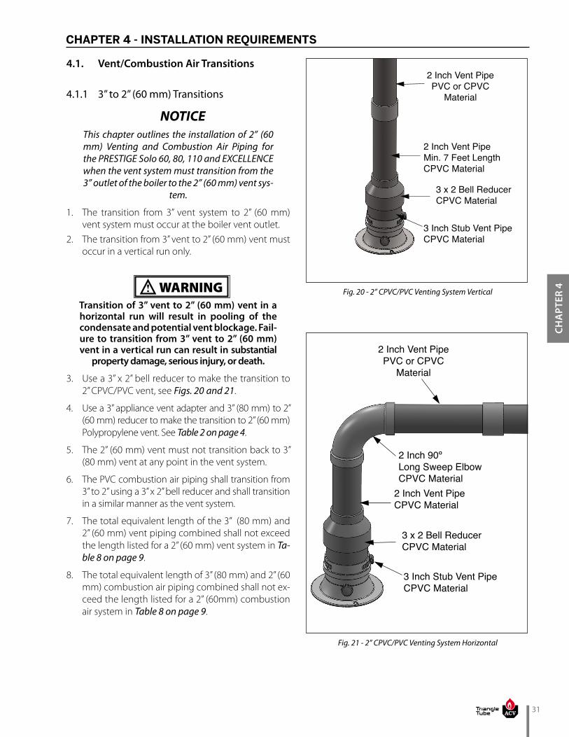
31
CHA
PTER
4
2 Inch Vent PipePVC or CPVC
Material
2 Inch Vent PipeMin. 7 Feet LengthCPVC Material
3 x 2 Bell ReducerCPVC Material
3 Inch Stub Vent PipeCPVC Material
Fig. 20 - 2” CPVC/PVC Venting System Vertical
2 Inch Vent PipePVC or CPVC
Material
2 Inch Vent PipeCPVC Material
2 Inch 90º Long Sweep ElbowCPVC Material
3 x 2 Bell ReducerCPVC Material
3 Inch Stub Vent PipeCPVC Material
CHAPTER 4 - INSTALLATION REQUIREMENTS
4.1. Vent/Combustion Air Transitions
4.1.1 3” to 2” (60 mm) Transitions
This chapter outlines the installation of 2” (60 mm) Venting and Combustion Air Piping for the PRESTIGE Solo 60, 80, 110 and EXCELLENCE when the vent system must transition from the 3” outlet of the boiler to the 2” (60 mm) vent sys-
tem.
1. The transition from 3” vent system to 2” (60 mm) vent system must occur at the boiler vent outlet.
2. The transition from 3” vent to 2” (60 mm) vent must occur in a vertical run only.
Transition of 3” vent to 2” (60 mm) vent in a horizontal run will result in pooling of the condensate and potential vent blockage. Fail-ure to transition from 3” vent to 2” (60 mm) vent in a vertical run can result in substantial
property damage, serious injury, or death.
3. Use a 3” x 2” bell reducer to make the transition to 2” CPVC/PVC vent, see Figs. 20 and 21.
4. Use a 3” appliance vent adapter and 3” (80 mm) to 2” (60 mm) reducer to make the transition to 2” (60 mm) Polypropylene vent. See Table 2 on page 4.
5. The 2” (60 mm) vent must not transition back to 3” (80 mm) vent at any point in the vent system.
6. The PVC combustion air piping shall transition from 3” to 2” using a 3” x 2” bell reducer and shall transition in a similar manner as the vent system.
7. The total equivalent length of the 3” (80 mm) and 2” (60 mm) vent piping combined shall not exceed the length listed for a 2” (60 mm) vent system in Ta-ble 8 on page 9.
8. The total equivalent length of 3” (80 mm) and 2” (60 mm) combustion air piping combined shall not ex-ceed the length listed for a 2” (60mm) combustion air system in Table 8 on page 9.
NOTICE
WARNING
Fig. 21 - 2” CPVC/PVC Venting System Horizontal

32
CHA
PTER 4
CHAPTER 4 - INSTALLATION REQUIREMENTS
4.1.2 3” to 4” (100 mm) Transitions
This Chapter outlines the installation of 4” (100 mm) Venting and Combustion Air piping for all PRESTIGE Solo models and the EXCELLENCE when the vent system must transition from the 3” outlet of the boiler to the 4” (100 mm) vent
system.
1. The transition from 3” vent system to 4” (100 mm) vent system must occur within 5 feet [1.5 m] of the boiler vent outlet.
2. The transition from 3” vent to 4” (100 mm) vent must occur in a vertical run only.
Transition of 3” vent to 4” (100 mm) vent in a horizontal run will result in pooling of the condensate and potential vent blockage. Fail-ure to transition from 3” vent to 4” (100 mm) vent in a vertical run can result in substantial
property damage, serious injury, or death.
3. Use a 4”x3” bell reducer to make the transition to 4” CPVC/PVC vent.
4. Use a 3” appliance vent adapter and 4” (100 mm) to 3” (80 mm) reducer to make the transition to 4” (100 mm) Polypropylene vent. See Table 4 on page 6.
5. The 4” (100 mm) vent must not transition back to 3” (80 mm) vent at any point in the vent system ex-cept when using ACV - Triangle Tube’s optional PVC concentric vent termination kit. See kit instructions for details.
6. The PVC combustion air piping shall transition from 3” to 4” (100 mm) using a 4”x3” bell reducer and shall transition in a similar manner as the vent system.
7. The total equivalent length of the 3” (80 mm) vent and 4” (100 mm) vent piping combined shall not exceed the length listed for a 4” (100 mm) vent sys-tem in Table 8 on page 9
8. The total equivalent length of 3” (80 mm) and 4” (100 mm) combustion air piping combined shall not exceed the length listed for a 4“ (100 mm) com-bustion air system in Table 8 on page 9.
NOTICE
WARNING
4.2. Connect Piping to PRESTIGE
1. The installer must clean, deburr and chamfer the pipe ends prior to assembly.
The pipe ends must be smooth, free of sharp edges, chamfered and wiped clean to prevent possible damage to the sealing gasket in the vent and combustion air adapters. Failure to comply with this requirement can cause flue gas leakage, resulting in substantial property
damage, serious injury, or death.2. Prior to inserting the pipe into the adapter:
• Verify the vent and combustion air adapters are securely attached to the top of the jacket by turning clockwise.
• Verify there is no packing material or obstruc-tions inside the adapters and the gaskets are in place.
3. Ensure the adapter retaining strap is loose prior to inserting the pipe.
4. Apply a small amount of water to the insertion end of the pipe to ease insertion into the adapter.
5. Insert the pipe into the adapter until it is fully seat-ed.
Do not bend, twist or apply excessive force to the vent or combustion air adapters when in-stalling the vent / combustion air piping. The adapter gasket could be damaged and leak flue gas, resulting in substantial property dam-
age, serious injury, or death.
6. Secure the vent and combustion air pipes by tight-ening the adapter retaining strap. Do not over tight-en the strap. The seal is made by the gasket inside the adapter.
WARNING
WARNING

33
CHA
PTER
4
CHAPTER 4 - INSTALLATION REQUIREMENTS
4.3. Vent and Combustion Air Piping Installation
4.3.1 PVC/CPVC Vent System1. The installer should install the vent / combustion air
piping working from the boiler to the piping termina-tion. The piping length must not exceed the lengths listed in Table 8 on page 9.
2. The installer should cut the pipe to the required length and must deburr the inside and outside of both ends.
3. The installer must chamfer the outside of the pipe ends to allow even distribution of cement when joining.
4. The installer must dry assemble the vent system prior to final assembly to ensure proper fit.
5. The pipe ends and fittings must be cleaned and dried thoroughly prior to final assembly.
6. When assembling a joint the installer must:a. Handle fittings and pipes carefully to prevent
contamination of surfacesb. Apply a liberal amount of primer to both the end
of the pipe and the insert socket of the fitting.c. Apply a light uniform coating of approved ce-
ment to both the end of the pipe and the insert socket of the fitting, while the primer is still wet.
d. A second coat of approved cement should be applied to the mating surfaces. The installer should avoid, however, using too much cement on the socket of the fitting to prevent a buildup of cement on the inside.
e. With the cement still wet, the pipe end should be inserted into the socket of the fitting and twisted 1/4 of a full turn. Ensure the pipe end is inserted fully into the socket of the fitting.
f. Any excess cement should be wiped clean from the joint. Inspect the joint to ensure a smooth bead of cement is around the entire joint seam.
7. The installer must use perforated metal strap hang-ers or equivalent pipe hangers suitable for plastic pipe to support the piping. The hangers must be placed at a maximum of every 5 feet [1.5 m] of hori-zontal and vertical run of piping. A support must be placed at the boiler and at every vertical or horizon-tal change in direction (i.e elbow). Do not penetrate any part of the piping or vent system with a fastener.
Failure to properly support vent system can cause the venting system to fail, resulting in substantial property damage, serious injury,
or death.
WARNING
Pipe hangers must not be tightly clamped to pipe to allow for thermal expansion/contraction move-ment. Pipe clamps or hangers should not contain
any sharp edges which can damage the pipe.
8. The vent and combustion air piping must be sloped continuously from the termination back to the boiler with at least 1/4” drop per foot [6 mm/30 cm] of run. Do not allow any sags in the run of piping.
Do not slope the vent or combustion air pip-ing downward away from the boiler. Conden-sate could freeze and block the vent pipe or damage the exterior of the building or sur-rounding landscape, resulting in substantial
property damage, serious injury, or death.9. Maintain a minimum clearance of 1/4” [6 mm]
between the vent pipe and all combustible or non-combustible materials for 3” and 4” PVC/CPVC vents or 1” [2.5 cm] for 2” PVC/CPVC vents. The install-er must seal any wall, floor or ceiling penetrations as per local code requirements.
It is recommended that the installer uses the same number of elbows and length of pipes on the venting and the combustion air inlet sys-
tems.
Covering PVC/CPVC or Polypropylene vent pipe and fittings with thermal insulation is prohibited.
4.3.2 Polypropylene or Stainless Steel Vent Sys-tems
• When using Polypropylene or Stainless Steel Vent, refer to vent manufacturer’s installation instructions supplied with the vent for proper in-
stallation.
• Covering Polypropylene vent pipe and fit-tings with thermal insulation is prohibited.
NOTICE
WARNING
BEST PRACTICE
NOTICE
NOTICE

34
CHA
PTER 4
CHAPTER 4 - INSTALLATION REQUIREMENTS
4.4. Carbon Monoxide Detector Installation
ACV-Triangle Tube requires the installation of a mini-mum of two (2) hard wired carbon monoxide detectors with an alarm and battery back-up in the mechanical room where the Prestige is located and another in-stalled in the living area outside the bedroom(s) for all installations. Each carbon monoxide detector shall comply with NFPA 720 and be ANSI/UL 2034 listed and IAS certified. Consult the local authority having jurisdiction for any additional carbon monoxide detector requirements in your area. See Chapter 6 on page 37 for additional carbon monoxide detector requirements in Massachu-setts.
A byproduct of any gas fired appliance is carbon monoxide. Failure to install carbon monoxide detectors with alarms can result in
serious injury, or death.
WARNING

35
CHA
PTER
5
Combined Maximum Input (MBH)
Minimum Diameter of Com-bustion Air Piping
<400 4”400-600 5”601-800 6”801-1600 8”
1601 -2000 10”
Table 9 - Common Combustion Air Piping
5.1. Manifold Combustion Air Option for Multiple Prestige Boilers
1. Common combustion air manifold is restricted to horizontal/side wall terminations only.
2. The number of Prestige boilers connected to a com-mon combustion air manifold system is limited by the combined maximum boiler input shown in Table 9.
3. The combustion air manifold must be constructed of round solid core PVC pipe with minimum diame-ter based on combined maximum boiler input. See Table 9 below.
5.3. Sidewall Termination
• The common combustion air manifold must termi-nate horizontally on a side wall using a 90° elbow pointed downward.
• The inlet elbow of the common combustion air termination must include a corrosion resistant field supplied bird screen.
• The edge of the common combustion air termina-tion coupling must extend 1” (2.5 cm) beyond the exterior wall as shown in Fig. 6 on page 19.
• The inlet of the common combustion air termina-tion must be located 12” (30.5 cm) minimum above grade/highest anticipated snow level.
• The common combustion air termination must be a minimum of 3 feet (0.9 m) below any appliance vent termination within 10 feet (3 m) horizontally.
• The common combustion air termination must be a minimum of 3 feet (0.9 m) horizontally from any appliance vent termination.
• Avoid locating the common combustion air termi-nation in a location where prevailing winds could affect the performance of the boilers or cause re-circulation of flue gases, such as inside corners of buildings, near adjacent buildings, vertical surfac-es, window wells, stairwells, alcoves, courtyards, or other recessed areas. The common combustion air termination must be installed a minimum of 6 feet horizontally from any such locations.
• Locate the common combustion air termination in a manner to protect from damage by foreign ob-jects, such as stones, balls, or buildup of leaves or sediment.
CHAPTER 5 - MANIFOLD COMBUSTION AIR
5.2. Combustion Air Manifold Equivalent Length
1. The maximum equivalent length of the combus-tion air manifold must not exceed the lowest maxi-mum allowable length for the boilers connected to the manifold per Table 8 on page 9.
2. Reduce the maximum equivalent length of the combustion air manifold as follows:• 5 Feet for every 45º elbow• 10 feet for every 90º elbow
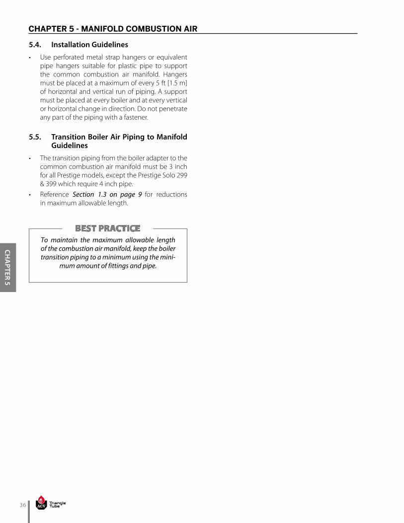
36
CHA
PTER 5
5.4. Installation Guidelines
• Use perforated metal strap hangers or equivalent pipe hangers suitable for plastic pipe to support the common combustion air manifold. Hangers must be placed at a maximum of every 5 ft [1.5 m] of horizontal and vertical run of piping. A support must be placed at every boiler and at every vertical or horizontal change in direction. Do not penetrate any part of the piping with a fastener.
5.5. Transition Boiler Air Piping to Manifold Guidelines
• The transition piping from the boiler adapter to the common combustion air manifold must be 3 inch for all Prestige models, except the Prestige Solo 299 & 399 which require 4 inch pipe.
• Reference Section 1.3 on page 9 for reductions in maximum allowable length.
To maintain the maximum allowable length of the combustion air manifold, keep the boiler transition piping to a minimum using the mini-
mum amount of fittings and pipe.
BEST PRACTICE
CHAPTER 5 - MANIFOLD COMBUSTION AIR
37
CHA
PTER
6
CHAPTER 6 - COMMONWEALTH OF MASSACHUSETTS INSTALLATION REQUIREMENTS
For all side wall horizontally vented gas fueled equip-ment installed in every dwelling, building or structure used in whole or in part for residential purposes, includ-ing those owned or operated by the Commonwealth and where the side wall exhaust vent termination is less than seven (7) feet above finished grade in the area of the venting, including but not limited to decks and porches, the following requirements shall be satisfied:
6.1. Installation of Carbon Monoxide Detec-tors.
1. At the time of installation of the side wall horizontal vented gas fueled equipment, the installing plumb-er or gasfitter shall observe that a hard wired car-bon monoxide detector with an alarm and battery back-up is installed on the floor level where the gas equipment is to be installed.
2. In addition, the installing plumber or gasfitter shall observe that a battery operated or hard wired car-bon monoxide detector with an alarm is installed on each additional level of the dwelling, building or structure served by the side wall horizontal vented gas fueled equipment.
3. It shall be the responsibility of the property own-er to secure the services of qualified licensed pro-fessionals for the installation of hard wired carbon monoxide detectors.a. In the event that the side wall horizontally vent-
ed gas fueled equipment is installed in a crawl space or an attic, the hard wired carbon mon-oxide detector with alarm and battery back-up may be installed on the next adjacent floor lev-el.
b. In the event that the requirements of this sub-division can not be met at the time of comple-tion of installation, the owner shall have a peri-od of thirty (30) days to comply with the above requirements; provided, however, that during said thirty (30) day period, a battery operated carbon monoxide detector with an alarm shall be installed.
6.2. Approved Carbon Monoxide Detectors.
Each carbon monoxide detector as required in accor-dance with the above provisions shall comply with NFPA 720 and be ANSI/UL 2034 listed and IAS certified.
6.3. Signage
A metal or plastic identification plate shall be perma-nently mounted to the exterior of the building at a min-imum height of eight (8) feet above grade directly in line with the exhaust vent terminal for the horizontally vented gas fueled heating appliance or equipment. The sign shall read, in print size no less than one half (1/2) inch in size, “GAS VENT DIRECTLY BELOW. KEEP CLEAR OF ALL OBSTRUCTIONS”.

38
CHA
PTER 6
CHAPTER 6 - COMMONWEALTH OF MASSACHUSETTS INSTALLATION REQUIREMENTS
6.4. Inspection.
The state or local gas inspector of the side wall horizon-tally vented gas fueled equipment shall not approve the installation unless, upon inspection, the inspector observes carbon monoxide detectors and signage in-stalled in accordance with the provisions of 248 CMR 5.08(2)(a) 1 through 4.
6.4.1 Exemptions
The following equipment is exempt from 248 CMR 5.08(2)(a) 1 through 4:1. The equipment listed in Chapter 10 entitled “Equip-
ment Not Required To Be Vented” in the most cur-rent edition of NFPA 54 as adopted by the Board; and
2. Product Approved side wall horizontally vented gas fueled equipment installed in a room or structure separate from the dwelling, building or structure used in whole or in part for residential purposes.
6.4.2 Manufacturer Requirements - Gas Equip-ment Venting System Provided.
When the manufacturer of Product Approved side wall horizontally vented gas equipment provides a venting system design or venting system components with the equipment, the instructions provided by the manufac-turer for installation of the equipment and the venting system shall include:
1. Detailed instructions for the installation of the vent-ing system design or the venting system compo-nents; and
2. A complete parts list for the venting system design or venting system.
6.4.3 Manufacturer Requirements - Gas Equip-ment Venting System Not Provided.
When the manufacturer of a Product Approved side wall horizontally vented gas fueled equipment does not provide the parts for venting the flue gases, but identifies “special venting systems”, the following re-quirements shall be satisfied by the manufacturer:
1. The referenced “special venting system” instruc-tions shall be included with the appliance or equipment installation instructions; and
2. The “special venting systems” shall be Product Approved by the Board, and the instructions for that system shall include a parts list and detailed installation instructions.
A copy of all installation instructions for all Product Approved side wall horizontally vented gas fueled equipment, all venting instructions, all parts lists for venting instructions, and/or all venting design in-structions shall remain with the appliance or equip-ment at the completion of the installation.

39
40

41

42
43
Additional quality water heating equipment available from ACV - Triangle Tube
SMART INDIRECT FIRED WATER HEATERS
TTP BRAZED PLATE HEAT EXCHANGERS
ACV-Triangle Tube - 1 Triangle Lane - Blackwood, NJ 08012
Tel: (856) 228 8881 - Fax: (856) 228 3584 - E-mail: [email protected]
1. For domestic water, snow melting, radiant floor.2. Plates made of stainless steel, with 99.9 % copper
brazing, ensuring a high resistance to corrosion3. Self cleaning and self descaling4. Computerized sizing available from ACV - Triangle
Tube5. Available in capacities from 25,000 BTU/hr to
5,000,000 BTU/hr
1. Exclusive Tank-in-Tank design2. Stainless steel construction3. Available in 7 sizes 4. Limited LIFETIME residential warranty5. 6 Year limited commercial warranty6. Self cleaning/self descaling design
PRESTIGE CONCENTRIC VENT KITPRESTIGE DIRECT VENT SIDE
WALL TERMINATION KIT