Predictions vs. Test Results for Leakage and Force...
23
33 rd Turbomachinery Research Consortium Meeting Analyses of Pocket Damper Seals and Combined Labyrinth-Brush Seals TRC-SEAL-02-2013 Weilian Shan Graduate Research Assistant Luis San Andrés Mast-Childs Professor May 2013 Year I Predictions vs. Test Results for Leakage and Force Coefficients of a Fully Partitioned Pocket Damper Seal and a Labyrinth Seal – Limitations of the Current Computational Model TRC Project 32514/15196PD 1
Transcript of Predictions vs. Test Results for Leakage and Force...
33rd Turbomachinery Research Consortium Meeting
Analyses of Pocket Damper Seals and Combined Labyrinth-Brush Seals
TRC-SEAL-02-2013
Weilian ShanGraduate Research Assistant
Luis San AndrésMast-Childs Professor
May 2013
Year I
Predictions vs. Test Results for Leakage and Force Coefficients of a Fully Partitioned Pocket Damper Seal and a Labyrinth Seal –Limitations of the Current Computational Model
TRC Project 32514/15196PD1
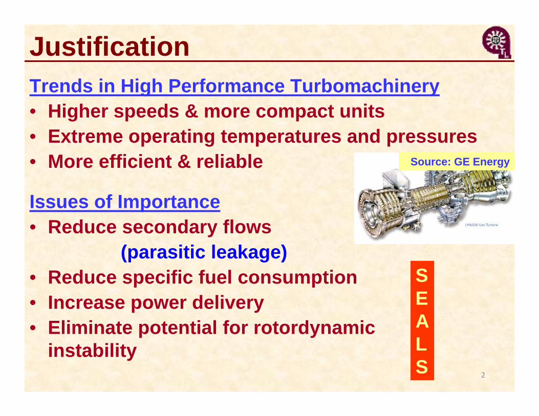
Trends in High Performance Turbomachinery• Higher speeds & more compact units• Extreme operating temperatures and pressures• More efficient & reliable
Issues of Importance• Reduce secondary flows
(parasitic leakage)• Reduce specific fuel consumption• Increase power delivery• Eliminate potential for rotordynamic
instability
Source: GE Energy
Justification
SEALS 2

Background
Ertas, B. H., 2005, Ph.D. Dissertation, Texas A&M University
Shaft (Rotor)
Interstage shaft seal
Impeller seal Balance piston seal
Labyrinth seals (LS) in a straight-through compressor
3
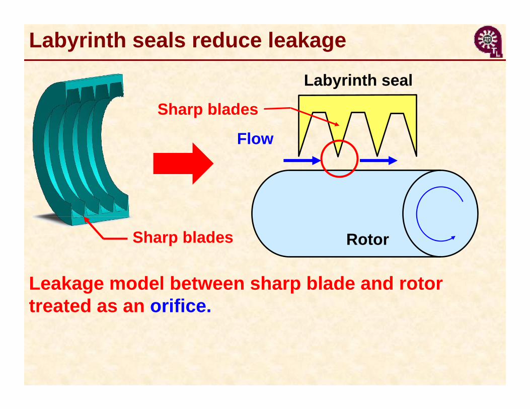
Leakage model between sharp blade and rotor treated as an orifice.
Sharp blades Rotor
Flow
Labyrinth seal
Sharp blades
Labyrinth seals reduce leakage
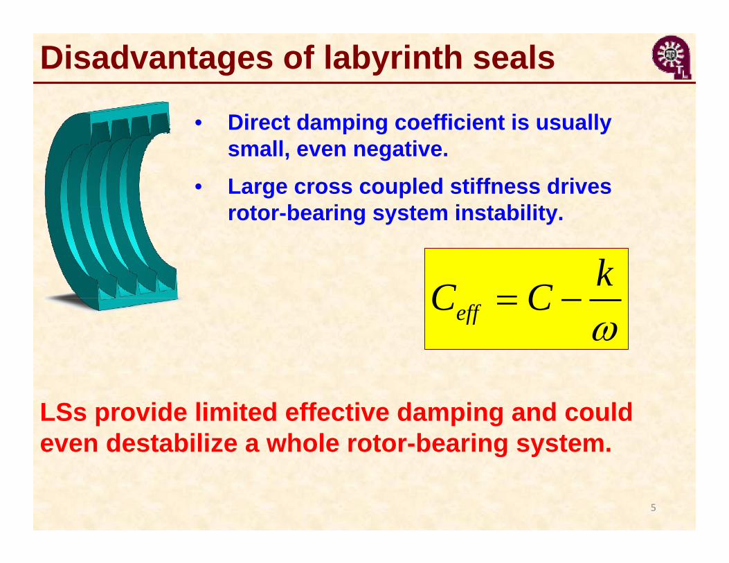
Disadvantages of labyrinth seals
LSs provide limited effective damping and could even destabilize a whole rotor-bearing system.
• Direct damping coefficient is usually small, even negative.
• Large cross coupled stiffness drives rotor-bearing system instability.
5
effkC C
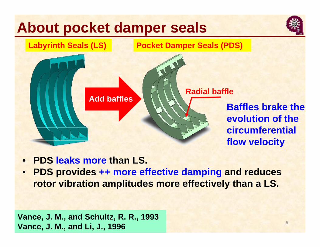
About pocket damper seals Labyrinth Seals (LS)
Add bafflesRadial baffle
Pocket Damper Seals (PDS)
• PDS leaks more than LS.• PDS provides ++ more effective damping and reduces
rotor vibration amplitudes more effectively than a LS.
Baffles brake the evolution of the circumferential flow velocity
6Vance, J. M., and Schultz, R. R., 1993Vance, J. M., and Li, J., 1996

TAMU PDSeal© code (1999)
2 21
( )ki
g
fi
ii
C C Hm P P
R T
1( ) ( )1 ( ) 0i i
r i iag
PA PAU m mR T t R
1
2
1( ) ( )1 ( )i i
ri i
ia a
i i i xig
PAU PAU A Pm U mUR T t R R
Neumman leakage model
Main flow equation
Circumferential momentum equation
Orifice
Wall shear stress difference(Moody’s friction factor)
Li, J., San Andrés, L., and Vance, J., 1999 7
Sharp blades
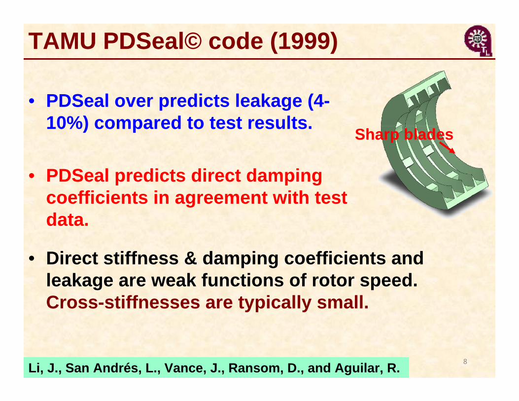
Sharp blades
• PDSeal predicts direct damping coefficients in agreement with test data.
• Direct stiffness & damping coefficients and leakage are weak functions of rotor speed. Cross-stiffnesses are typically small.
• PDSeal over predicts leakage (4-10%) compared to test results.
Li, J., San Andrés, L., Vance, J., Ransom, D., and Aguilar, R. 8
TAMU PDSeal© code (1999)
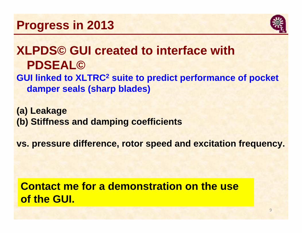
Progress in 2013
9
XLPDS© GUI created to interface with PDSEAL©
GUI linked to XLTRC2 suite to predict performance of pocket damper seals (sharp blades)
(a) Leakage(b) Stiffness and damping coefficients
vs. pressure difference, rotor speed and excitation frequency.
Contact me for a demonstration on the use of the GUI.
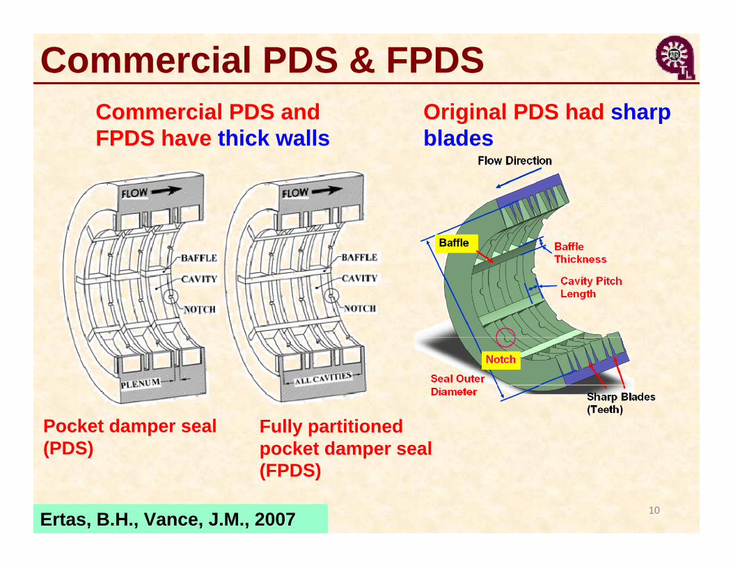
Commercial PDS & FPDS
Fully partitioned pocket damper seal (FPDS)
Pocket damper seal(PDS)
Ertas, B.H., Vance, J.M., 2007
Commercial PDS and FPDS have thick walls
Original PDS had sharp blades
10

Examples – seals geometry
14 bladed LS 8 bladed, 8 pocket FPDS
Blades properties All active Active / Inactive (without notch / with notch)
Cavity depth 4 mm 3.175 mmCavity axial length 5 mm 14 mm / 6.35 mm Blade thickness (tip) ~ 0 6.35 mm / 3.175 mm Radial clearance 0.3 mm 0.3 mmSeal overall length 65 mm 103 mmRotor diameter 170 mm 170 mm
LS FPDSErtas, B.H., Delgado, A., Vannini, G., 2012
11
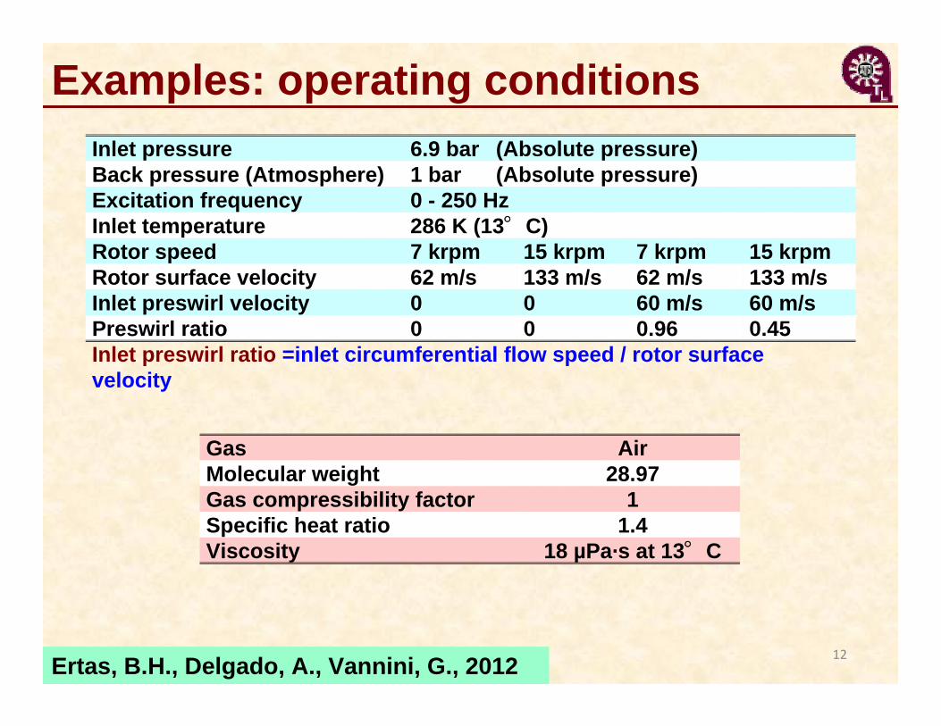
Examples: operating conditionsInlet pressure 6.9 bar (Absolute pressure)Back pressure (Atmosphere) 1 bar (Absolute pressure)Excitation frequency 0 - 250 HzInlet temperature 286 K (13°C)Rotor speed 7 krpm 15 krpm 7 krpm 15 krpmRotor surface velocity 62 m/s 133 m/s 62 m/s 133 m/sInlet preswirl velocity 0 0 60 m/s 60 m/sPreswirl ratio 0 0 0.96 0.45Inlet preswirl ratio =inlet circumferential flow speed / rotor surface velocity
Gas AirMolecular weight 28.97Gas compressibility factor 1Specific heat ratio 1.4Viscosity 18 µPa·s at 13°C
Ertas, B.H., Delgado, A., Vannini, G., 2012 12
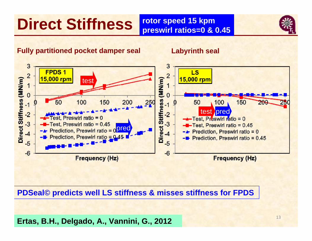
Direct Stiffness rotor speed 15 kpmpreswirl ratios=0 & 0.45
Ertas, B.H., Delgado, A., Vannini, G., 2012 13
Fully partitioned pocket damper seal Labyrinth seal
test
pred
test pred
PDSeal© predicts well LS stiffness & misses stiffness for FPDS
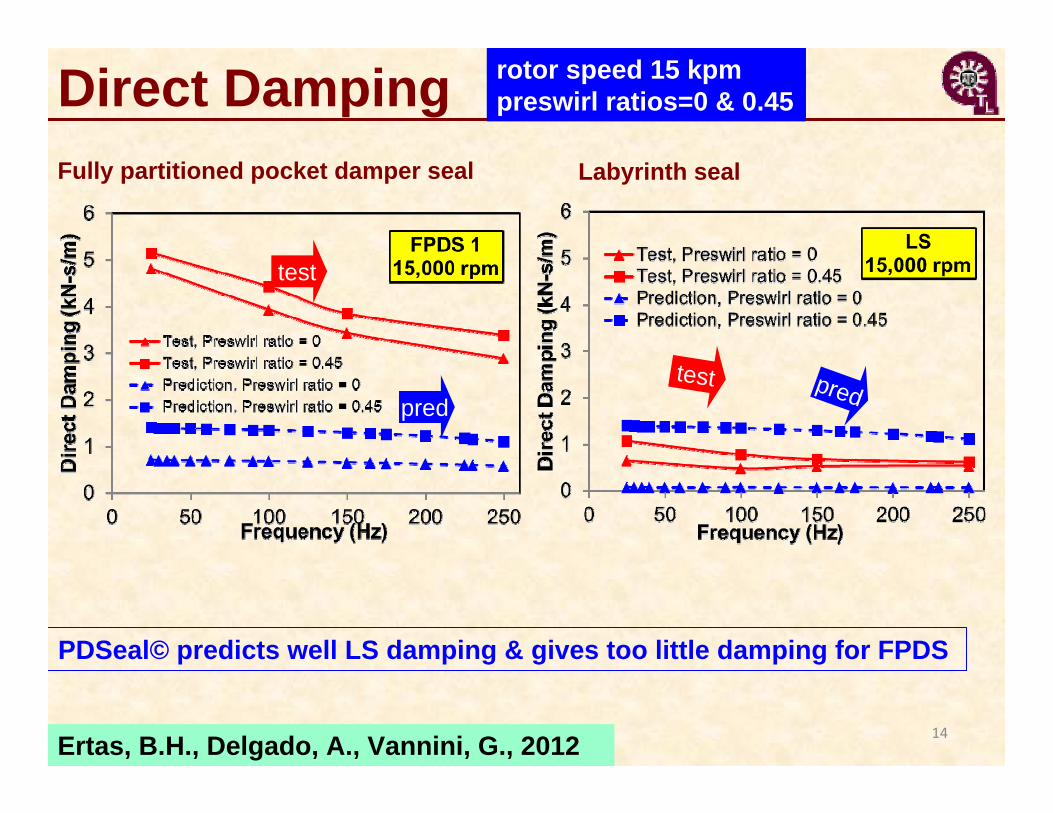
Direct Damping
Ertas, B.H., Delgado, A., Vannini, G., 2012 14
rotor speed 15 kpmpreswirl ratios=0 & 0.45
Fully partitioned pocket damper seal Labyrinth seal
PDSeal© predicts well LS damping & gives too little damping for FPDS
test
predtest pred
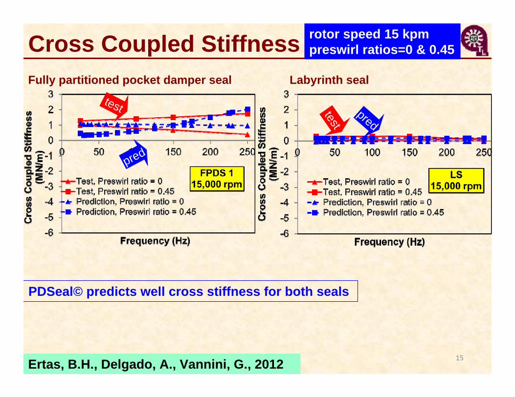
Cross Coupled Stiffness
Ertas, B.H., Delgado, A., Vannini, G., 2012 15
test
pred
test
pred
PDSeal© predicts well cross stiffness for both seals
rotor speed 15 kpmpreswirl ratios=0 & 0.45
Fully partitioned pocket damper seal Labyrinth seal
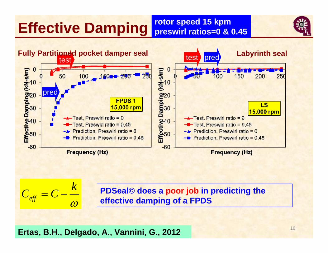
Effective Damping
Ertas, B.H., Delgado, A., Vannini, G., 2012 16
effkC C
test
pred
test pred
PDSeal© does a poor job in predicting the effective damping of a FPDS
rotor speed 15 kpmpreswirl ratios=0 & 0.45
Fully Partitioned pocket damper seal Labyrinth seal
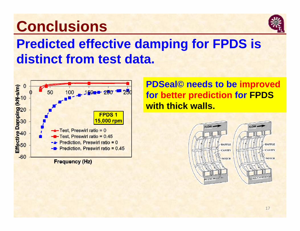
Conclusions
PDSeal© needs to be improved for better prediction for FPDS with thick walls.
Predicted effective damping for FPDS is distinct from test data.
17
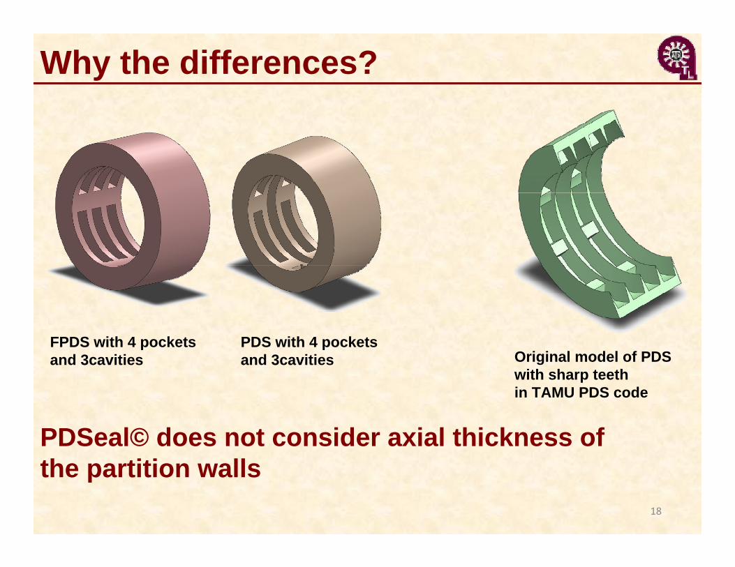
Why the differences?
PDSeal© does not consider axial thickness of the partition walls
FPDS with 4 pockets and 3cavities Original model of PDS
with sharp teeth in TAMU PDS code
PDS with 4 pockets and 3cavities
18
2013 Continuation Proposal to TRC
Engineering Analyses for Pocket Damper Seals and Combined Labyrinth-Brush Seals
19
May 2013
Weilian ShanGraduate Research Assistant
Luis San AndrésMast-Childs Professor

• Update bulk-flow flow model for PDS and FPDS.• Model will include real gas properties including
supercritical CO2 and steam.
• Perform more code calibrations: compare predictions to test data for leakage and force coefficients.
• Begin extensions of the model to include two-component mixtures (liquid and gas).
20
Proposed work 2013-2014 Year II
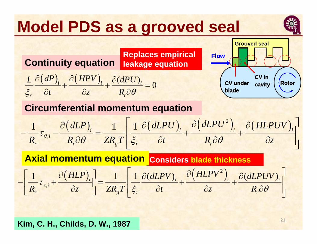
Model PDS as a grooved seal
Kim, C. H., Childs, D. W., 1987
Considers blade thickness
21
( ) 0i i i
r r
HPdPLt R
V dPUz
2
,1 1 1i i i i
ir r g r r
dLPUdLP dLPU HLR R T t R
PUVZR z
2
,( )1 (1 )1 i i i i
z ir g r r
HLPVHLP dLPV dLPUVR z ZR tT Rz
Continuity equation
Circumferential momentum equation
Axial momentum equation
Replaces empirical leakage equation
RotorCV under blade
Grooved seal
CV in cavity
Flow
RotorCV under blade
Grooved seal
CV in cavity
Flow
RotorCV under blade
Grooved seal
CV in cavity RotorCV under
blade
Grooved seal
RotorCV under blade
RotorCV under blade
Grooved sealGrooved seal
CV in cavity
Flow

Year IISupport for graduate student (20 h/week) x $ 1,950 x 12 months
$ 23,400
Fringe benefits (0.6%) and medical insurance ($185/month)
$ 2,360
Travel to (US) technical conference $ 1,200Tuition & fees three semesters ($362/credit hour x 24) $ 8,686Others (Mathcad® and portable data storage) $ 220
Total Cost: $ 35,866
Year 2: Develop computational models for predictions of leakage, drag power and force coefficients of FPDS, and combined labyrinth-bush seals for gas and steam turbines
22
TRC Budget 2013-2014 Year II

Thank you !
More information at:http://rotorlab.tamu.edu