Predicting and Avoiding Die Attach, Wire Bond, and Solder ... and... · 9000 Virginia Manor Rd Ste...
51
1 9000 Virginia Manor Rd Ste 290, Beltsville MD 20705 | 301-474-0607 | www.dfrsolutions.com Predicting and Avoiding Die Attach, Wire Bond, and Solder Joint Failures Craig Hillman June 15, 2016 Raleigh, NC 3D Power Electronics
Transcript of Predicting and Avoiding Die Attach, Wire Bond, and Solder ... and... · 9000 Virginia Manor Rd Ste...
19000 Virginia Manor Rd Ste 290, Beltsville MD 20705 | 301-474-0607 | www.dfrsolutions.com
Predicting and Avoiding Die Attach,
Wire Bond, and Solder Joint Failures
Craig Hillman
June 15, 2016 Raleigh, NC3D Power Electronics

29000 Virginia Manor Rd Ste 290, Beltsville MD 20705 | 301-474-0607 | www.dfrsolutions.com
o Interconnects tend to be the
primary driver for reliability
of power modules
o Influenced by the robustness
of today’s power devices
(IGBT and FET, Si/GaN/SiC) and the tendency
to towards conservative design (derating margin)
Why Die Attach/Wire Bonds/Solder Joints?
Active endurance tests of direct-bonded-copper based MOSFET power
modules showed that the aluminum bonds and the die attach are the
most critical design elements regarding product reliability – Robert
Bosch, 2016

39000 Virginia Manor Rd Ste 290, Beltsville MD 20705 | 301-474-0607 | www.dfrsolutions.com
o Step 1: Good quality control
o Step 2: Perform reliability prediction using physics of
failure (PoF)
How to Avoid Die Attach, Wire Bond Failures?

49000 Virginia Manor Rd Ste 290, Beltsville MD 20705 | 301-474-0607 | www.dfrsolutions.com
What is Physics of Failure (PoF)?
o Also known as reliability physics
o Common Definition:
o The process of using modeling
and simulation based on the
fundamentals of physical
science (physics, chemistry,
material science, mechanics,
etc.) to predict reliability and
prevent failures
59000 Virginia Manor Rd Ste 290, Beltsville MD 20705 | 301-474-0607 | www.dfrsolutions.com
o What are we modeling / simulating?
o Reliability (t > 0) = Material Change or Material
Movement
o Fundamental Material Mechanisms
o Diffusion
o Oxidation/Reduction
o Creep
o Fatigue
Physics of Failure: Modeling and Simulation

69000 Virginia Manor Rd Ste 290, Beltsville MD 20705 | 301-474-0607 | www.dfrsolutions.com
o Motion of electrons, atoms, ions, or vacancies through a
material
o Typically driven by a
concentration gradient
(Fick’s Law)
o Can be driven by other forces (electromotive force, stress)
Material Movement: Diffusion

79000 Virginia Manor Rd Ste 290, Beltsville MD 20705 | 301-474-0607 | www.dfrsolutions.com
o The tendency of a solid to permanently deform when
subjected to a fixed load
o Corollary: Tendency of a solid to relieve stress when loaded
at a fixed displacement
o Metals: Driven by movement of defects within the
crystalline structure
o Dislocations (edge or screw)
o Grain Boundaries
Material Movement: Creep

89000 Virginia Manor Rd Ste 290, Beltsville MD 20705 | 301-474-0607 | www.dfrsolutions.com
o All physics of failure models can be condensed into
answers to three questions
o How large is the stress?
o At what rate is this stress driving material
movement?
o At what time will this material movement induce
failure?
Material Movement and M&S

99000 Virginia Manor Rd Ste 290, Beltsville MD 20705 | 301-474-0607 | www.dfrsolutions.com9
o Most physics-of-failure (PoF) based models are semi-empirical
o The basic concept is still valid
o Requires calibration
o Calibration testing should be performed over several orders of magnitudes
o Allows for the derivation of semi-empirical constants, if necessary
o The purpose of PoF is to limit, but not eliminate, the influence of material and geometric parameters
o E.g., Solder: Testing must be re-performed for each package family (ball array devices, gullwing, leadless, etc.)
PoF-Based Reliability Prediction

109000 Virginia Manor Rd Ste 290, Beltsville MD 20705 | 301-474-0607 | www.dfrsolutions.com
o One of the key differentiations in PoF techniques is how to
capture the stress/strain/energy within the interconnect
o Most manufacturers will use Option 1 at some point during the
development process (especially for complex geometries)
o However, Option 2 is preferred for tradeoff analysis and for
users of the power modules
How to Perform PoF? Stress/Strain/Energy
Option 1: Finite element model
T
LD121
D
L
D
r6 wirebase
base
5.0
Option 2: Analytical Equations

119000 Virginia Manor Rd Ste 290, Beltsville MD 20705 | 301-474-0607 | www.dfrsolutions.com
Coffin-Manson
(low-cycle)
Basquin
(high-cycle)
o Lots of discussion about
key damage parameter
(stress, strain, elastic,
plastic, plasticity, creep,
energy)
How to Perform PoF? Damage Accumulation
Paris
(high-cycle)
Darveaux
(low-cycle)
129000 Virginia Manor Rd Ste 290, Beltsville MD 20705 | 301-474-0607 | www.dfrsolutions.com
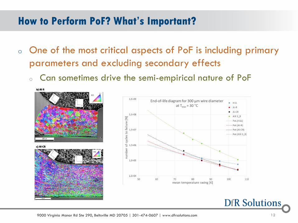
o One of the most critical aspects of PoF is including primary
parameters and excluding secondary effects
o Can sometimes drive the semi-empirical nature of PoF
How to Perform PoF? What’s Important?

139000 Virginia Manor Rd Ste 290, Beltsville MD 20705 | 301-474-0607 | www.dfrsolutions.com
Predicting Reliability of Die Attach

149000 Virginia Manor Rd Ste 290, Beltsville MD 20705 | 301-474-0607 | www.dfrsolutions.com
o Die attach tends to have only one failure mode
o Thermal cycle fatigue due to power cycling
o Frequency of the power cycle can play a very critical role
o If the power cycle frequency is high enough, the failure site
will shift from the die attach to the wire bond (thermal inertia)
o Key Challenge: Defining failure
o Most die attach configurations do not conduct electricity
o Die attach is primarily a thermal path
Predicting the Reliability of Die Attach

159000 Virginia Manor Rd Ste 290, Beltsville MD 20705 | 301-474-0607 | www.dfrsolutions.com
Die Attach Fatigue (Englemaier, 1982)
Strain range at the die/die attach interface
• h = die thickness
• W = die width
• L = die length
• = coefficient of
thermal expansion
(CTE)
• T = change in
temperature
h
TCTECTEWL DBCdiedd
2
))((22
169000 Virginia Manor Rd Ste 290, Beltsville MD 20705 | 301-474-0607 | www.dfrsolutions.com
o Coffin-Mason based low-cycle fatigue damage model
o Tin-based solders (SnPb, SAC305, Sn3.5Ag, etc.) tend to have fatigue exponents around 2 to 2.5
o SnPb: ~2; Sn3.5Ag: 2.2; SAC305: ~2.4
o Fatigue exponents for new die attach solders have not yet been widely validated
o Nanosilver, BiAgX, Sn25Ag10Sb (“J” alloy)
Die Attach Fatigue (Time to Failure)
c
ffN )(
179000 Virginia Manor Rd Ste 290, Beltsville MD 20705 | 301-474-0607 | www.dfrsolutions.com
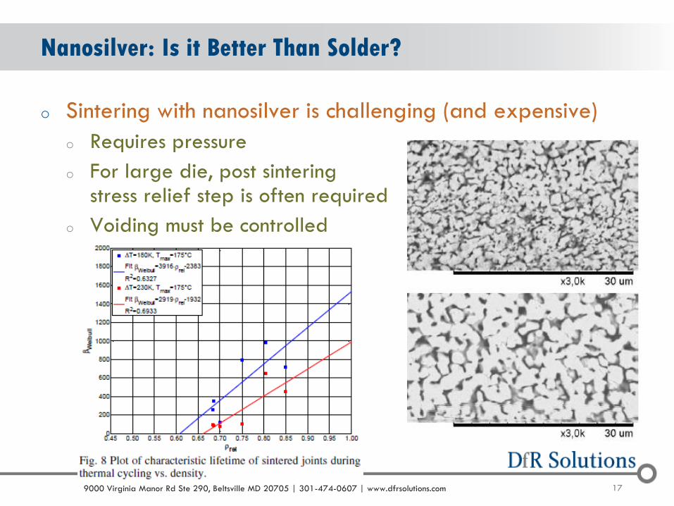
o Sintering with nanosilver is challenging (and expensive)
o Requires pressure
o For large die, post sintering stress relief step is often required
o Voiding must be controlled
Nanosilver: Is it Better Than Solder?

189000 Virginia Manor Rd Ste 290, Beltsville MD 20705 | 301-474-0607 | www.dfrsolutions.com
o For the most part, the industry agrees nanosilver is more reliable, but there can be issues
Nanosilver: Is it Better Than Solder? (cont.)
L. Melchor, Doctoral DissertationM. Beierlein, Adv. Pack. Conf. 2013

199000 Virginia Manor Rd Ste 290, Beltsville MD 20705 | 301-474-0607 | www.dfrsolutions.com
o Different publications
provide different values for
fatigue constants and
exponents
Nanosilver: Is it Better Than Solder? (cont.)
Y. Tan, et. al., Conf. on Fracture, 2013
Author Constant Value Exponent
M. Knoerr 1.6E-01 Plastic Strain -3.0
Y. Tan 5.8E+11 Shear Stress -9.4
X. Li 1.6E-09 Shear Strain -7.6

209000 Virginia Manor Rd Ste 290, Beltsville MD 20705 | 301-474-0607 | www.dfrsolutions.com20
Lifetime under mechanical cycling
is divided into two regimes Low cycle fatigue (LCF)
High cycle fatigue (HCF)
LCF is driven by inelastic strain
(Coffin-Manson)
HCF is driven by elastic strain
(Basquin)
Vibration Fatigue
b
f
f
e NE
2
c
ffp N2 -0.5 < c < -0.7; 1.4 < -1/c > 2
-0.05 < b < -0.12; 8 > -1/b > 20

219000 Virginia Manor Rd Ste 290, Beltsville MD 20705 | 301-474-0607 | www.dfrsolutions.com
Predicting Reliability of Wire Bonds

229000 Virginia Manor Rd Ste 290, Beltsville MD 20705 | 301-474-0607 | www.dfrsolutions.com
o Exposure to elevated temperature
o Intermetallic formation
o Exposure to elevated temperature/humidity
o Corrosion
o Exposure to temperature cycling
o Low cycle fatigue
Reliability: When do Wire Bonds Fail?

239000 Virginia Manor Rd Ste 290, Beltsville MD 20705 | 301-474-0607 | www.dfrsolutions.com
o Not an issue in aluminum-aluminum wire bond system
o The lack of intermetallic formation and differential diffusion makes it relatively immune to purple plague
o Prior studies have found little change in resistance after 1000 hours at 300C
o Bigger issue in mixed metalsystems, like gold-aluminum
o Formation of brittle AuAl2 (purple plague) at 350C
o Diffusion of gold into Au5Al2 causesKirkendall voiding at lower temps
Reliability at Elevated Temperatures
249000 Virginia Manor Rd Ste 290, Beltsville MD 20705 | 301-474-0607 | www.dfrsolutions.com
o Is an absolute reliability prediction of wire bond reliability at elevated temperature possible?
o Short answer: NO
o Diffusion behavior is very sensitive to bonding temperature, quality of bond, aluminum alloy, aluminum bond pad thickness, and encapsulant chemistry
o Low bonding temperature
o Si in Al-Cu bond pad
o Thin bond pad (~1 um)
o Bromide-free flame retardants
o Can change absolute and relative (acceleration factor) time to failure
Reliability Prediction (Elevated Temperature)

259000 Virginia Manor Rd Ste 290, Beltsville MD 20705 | 301-474-0607 | www.dfrsolutions.com
o For gold-aluminum, prediction is primarily by extrapolation from test results using Arrhenius and a conservative activation energy (0.9 eV)
o However, there is some question as to the presence of a minimum temperature
o Periodically reported as 125C for unencapsulated and 85C for encapsulated
o Observed in other systems (tin-copper and whiskers)
Reliability Prediction – Temperature (cont.)
kT
HAt f exp
269000 Virginia Manor Rd Ste 290, Beltsville MD 20705 | 301-474-0607 | www.dfrsolutions.com
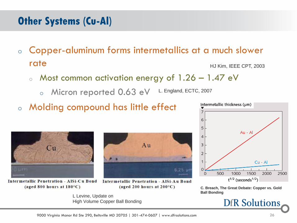
o Copper-aluminum forms intermetallics at a much slower
rate
o Most common activation energy of 1.26 – 1.47 eV
o Micron reported 0.63 eV
o Molding compound has little effect
Other Systems (Cu-Al)
HJ Kim, IEEE CPT, 2003
L Levine, Update on
High Volume Copper Ball Bonding
L. England, ECTC, 2007
C. Breach, The Great Debate: Copper vs. Gold
Ball Bonding

279000 Virginia Manor Rd Ste 290, Beltsville MD 20705 | 301-474-0607 | www.dfrsolutions.com
o Cu-Al can show improved performance over Au-Al
o Not to the extent expected based on intermetallic growth
o Different failure mode (gradual vs. sudden)
Other Systems (Cu-Al)(cont.)
Cu-Al
Au-Al

289000 Virginia Manor Rd Ste 290, Beltsville MD 20705 | 301-474-0607 | www.dfrsolutions.com
o Shear strength of Au and Cu ball bonds on Al pads
o At lower temperatures (<150C) they are similar in strength loss
Shear Strength at Elev Temp
J. Onuki, M. Koizumi, I. Araki. IEEE Trans. On Comp. Hybrids & Manfg. Tech. 12 (1987) 550
a. b.
Cu
Gold Wire Copper Wire
Cu

299000 Virginia Manor Rd Ste 290, Beltsville MD 20705 | 301-474-0607 | www.dfrsolutions.com
o Different intermetallics form at different temperatures
o Can a 150C/200C test be extrapolated to 85C?
o Fracture mode with pure Cu changed from bulk Cu to interfacial failure
o Some indications that oxidation of the wedge bond may be a critical weak point
Cu-Al and Elevated Temperature – Concerns
S. Na, T. Hwang, J. Kim, H. Yoo, and C. Lee, “Characterization of IMC growth in Cu wire ball bonding on Al pad
metallization”, ECTC, IEEE, 2011
309000 Virginia Manor Rd Ste 290, Beltsville MD 20705 | 301-474-0607 | www.dfrsolutions.com
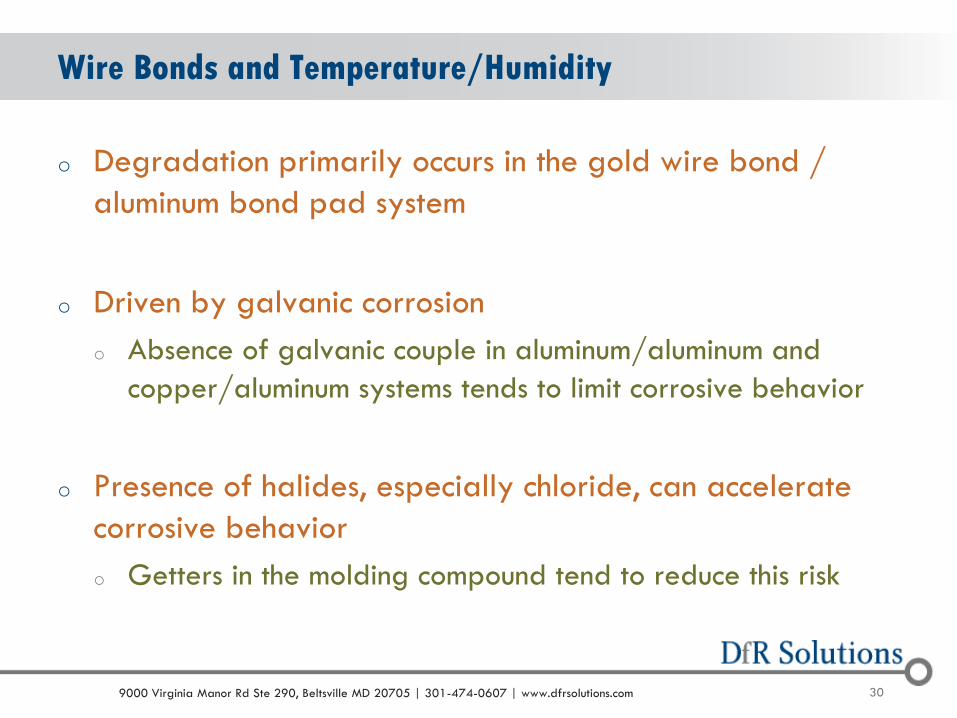
o Degradation primarily occurs in the gold wire bond /
aluminum bond pad system
o Driven by galvanic corrosion
o Absence of galvanic couple in aluminum/aluminum and
copper/aluminum systems tends to limit corrosive behavior
o Presence of halides, especially chloride, can accelerate
corrosive behavior
o Getters in the molding compound tend to reduce this risk
Wire Bonds and Temperature/Humidity
319000 Virginia Manor Rd Ste 290, Beltsville MD 20705 | 301-474-0607 | www.dfrsolutions.com
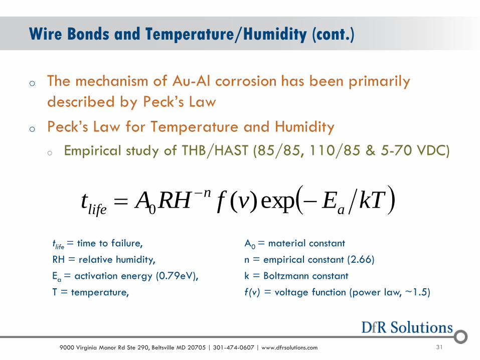
o The mechanism of Au-Al corrosion has been primarily
described by Peck’s Law
o Peck’s Law for Temperature and Humidity
o Empirical study of THB/HAST (85/85, 110/85 & 5-70 VDC)
Wire Bonds and Temperature/Humidity (cont.)
tlife = time to failure, A0 = material constant
RH = relative humidity, n = empirical constant (2.66)
Ea = activation energy (0.79eV), k = Boltzmann constant
T = temperature, f(v) = voltage function (power law, ~1.5)
kTEvfRHAt a
n
life exp)(0

329000 Virginia Manor Rd Ste 290, Beltsville MD 20705 | 301-474-0607 | www.dfrsolutions.com
o Copper is not as noble as gold
o Noble coatings (palladium) can come off during bonding
o Palladium (Pd) coating can also create galvanic couple with copper
o Studies have shown early failures during temp/humidity testing
o Some dependency on molding compound (need lower pH, lower halogen content)
o Uncertain if JEDEC test with acceleration factor based on Peck’s equation (based on aluminum/gold) is still valid
Copper Wire Bond and Temperature/Humidity
H. Clauberg, Chip Scale Review, Dec 2010
Halogen-Free Molding Compounds

339000 Virginia Manor Rd Ste 290, Beltsville MD 20705 | 301-474-0607 | www.dfrsolutions.com
o T. Boettcher believe early failures are due to galvanic
corrosion of Cu-rich intermetallics (Cu9Al4) (EPTC 2010)
o Induces the formation of copper oxides between the
intermetallic and the copper bond wire
o Initial failures during JEDEC HTRB and Autoclave testing
were reversed by increasing the amount of intermetallic
through annealing
o Small anode (intermetallic) relative to cathode greatly
increases corrosion rate
Copper Wire Bond and Temperature/Humidity (cont.)

349000 Virginia Manor Rd Ste 290, Beltsville MD 20705 | 301-474-0607 | www.dfrsolutions.com
o iNEMI Phase 2B: HAST 130degC/85% Rel. Humidity for 384
hours on loose parts
o Tested every 4 days at 96, 192, 288 and 384 hours.
o Failure pattern suggests more of a durability issue (however, how
relevant is 384 hours under HAST?)
Status of Cu-WB Durability-Reliability Research iNEMI P2B

359000 Virginia Manor Rd Ste 290, Beltsville MD 20705 | 301-474-0607 | www.dfrsolutions.com
Wire Bonds and Temperature Cycling (Wedge Flexure)
o Driven by differences in coefficient of thermal expansion (CTE)
o Flexing motion results create microcracks at the heel of the
wirebond
o Model based on theory of curved beams
Strain at the heel of the wire
(assumes bond pads at same height)
T
LD121
D
L
D
r6 wirebase
base
5.0
• r = wire radius
• D = half wire span
• L = wire length
• = coefficient of thermal expansion
(CTE)
• T = change in temperature

369000 Virginia Manor Rd Ste 290, Beltsville MD 20705 | 301-474-0607 | www.dfrsolutions.com
o Coffin-Mason Based Low-Cycle Fatigue
o C and m empirically determined to be 1.0 and (-1.4)
respectively for aluminum wedge bonds
Wedge Flexure (cont.)
mf CN

379000 Virginia Manor Rd Ste 290, Beltsville MD 20705 | 301-474-0607 | www.dfrsolutions.com
Wire Bonds and Temperature Cycling (Axial Tension)
o Wire encapsulated in molding compound can
experience tensile stresses in the wire due to
differential expansion and contraction
Modulus of molding compound is ignored
because of its minimal contribution
m
f CN

389000 Virginia Manor Rd Ste 290, Beltsville MD 20705 | 301-474-0607 | www.dfrsolutions.com
o Shear stresses between the substrate (s), the bond pad (p)
and the wire (w)
Wire Bonds and Temperature Cycling (Shear)
o r is wire radius
o A is cross-sectional area
o W is width
o G is shear modulus
o b is thickness
o l is length

399000 Virginia Manor Rd Ste 290, Beltsville MD 20705 | 301-474-0607 | www.dfrsolutions.com
Competing Failure Mechanisms

409000 Virginia Manor Rd Ste 290, Beltsville MD 20705 | 301-474-0607 | www.dfrsolutions.com
Validation (Aluminum-Aluminum System)

419000 Virginia Manor Rd Ste 290, Beltsville MD 20705 | 301-474-0607 | www.dfrsolutions.com
o Power module industry believes copper wire is more robust
than aluminum
o Changes being implemented for electric drivetrain
o Part of improvement is believed to be
due to reduced temperature variation
from improved thermal conductivity
o Part of improvement could be due to
recrystallization
o Can result in self-healing
o Part of improvement could be more robust fatigue behavior
Copper Wire and Temperature Cycling
D. Siepe, CIPS 2010
N. Tanabe, Journal de Physique IV, 1995

429000 Virginia Manor Rd Ste 290, Beltsville MD 20705 | 301-474-0607 | www.dfrsolutions.com
o Copper superior based on these publications
Copper vs. Gold – Temperature Cycling
N. Tanabe, Journal de Physique IV, 1995
G. Pasquale, J. Microelectromech Sys.,, 2011
439000 Virginia Manor Rd Ste 290, Beltsville MD 20705 | 301-474-0607 | www.dfrsolutions.com
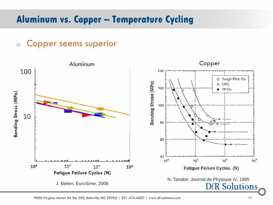
o Copper seems superior
Aluminum vs. Copper – Temperature Cycling
10
100
106 108107 109
Aluminum
N. Tanabe, Journal de Physique IV, 1995J. Bielen, EuroSime, 2006
Copper
Fatigue Failure Cycles (N)
Bendin
g S
tress
(M
Pa)

449000 Virginia Manor Rd Ste 290, Beltsville MD 20705 | 301-474-0607 | www.dfrsolutions.com
o Loose Cu wire-bonded parts have passed component level
thermal cycle tests, but have failed during thermal cycling
of automotive E/E modules
o Believed, but not confirmed, to be due to additional
expansion-contraction stresses from the CTE mismatch part
and PCB
Thermal Cycling Reliability and Assembled Parts

459000 Virginia Manor Rd Ste 290, Beltsville MD 20705 | 301-474-0607 | www.dfrsolutions.com
Predicting Reliability of Solder Joints
469000 Virginia Manor Rd Ste 290, Beltsville MD 20705 | 301-474-0607 | www.dfrsolutions.com
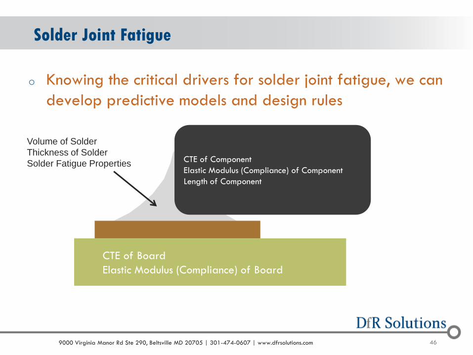
o Knowing the critical drivers for solder joint fatigue, we can
develop predictive models and design rules
Solder Joint Fatigue
CTE of Board
Elastic Modulus (Compliance) of Board
CTE of Component
Elastic Modulus (Compliance) of Component
Length of Component
Volume of Solder
Thickness of Solder
Solder Fatigue Properties

479000 Virginia Manor Rd Ste 290, Beltsville MD 20705 | 301-474-0607 | www.dfrsolutions.com
Predictive Models – Physics of Failure (PoF)
o Modified Engelmaier for Pb-free Solder (SAC305)
o Semi-empirical analytical approach
o Energy based fatigue
o Determine the strain range ()
o C is a correction factor that is a function of dwell time and temperature, LD is diagonal distance, is coefficient of thermal expansion (CTE), T is temperature cycle, h is solder joint height
Th
LC
s
D

489000 Virginia Manor Rd Ste 290, Beltsville MD 20705 | 301-474-0607 | www.dfrsolutions.com
Predictive Models – Physics of Failure (PoF)(cont.)
o Determine the shear force applied to the solder joint
o F is shear force, L is length, E is elastic modulus, A is the area, h
is thickness, G is shear modulus, and a is edge length of bond pad
o Subscripts: 1 is component, 2 is board, s is solder joint, c is bond
pad, and b is board
o Takes into consideration foundation stiffness and both
shear and axial loads
aGGA
h
GA
h
AE
L
AE
LFLT
bcc
c
ss
s
9
2
221112

499000 Virginia Manor Rd Ste 290, Beltsville MD 20705 | 301-474-0607 | www.dfrsolutions.com
Predictive Models – Physics of Failure (PoF)(cont.)
o Determine the strain energy dissipated by the
solder joint
o Calculate cycles-to-failure (N50), using energy
based fatigue models
10019.0
WN f
sA
FW 5.0

509000 Virginia Manor Rd Ste 290, Beltsville MD 20705 | 301-474-0607 | www.dfrsolutions.com
o Energy-based analytical
equation shows strong
correlation to both test and
field failures
o When correlation is not
observed, typically driven by
the presence of an axial
loading condition (constraints,
potting)
o Requires use of compatibility
of displacements
Solder Joint Validation
2211
12
11
EAEA
TF
BGA

519000 Virginia Manor Rd Ste 290, Beltsville MD 20705 | 301-474-0607 | www.dfrsolutions.com
Summary / Conclusion
o The field of reliability prediction is not stagnant
o Driven by need for new materials, new technologies
o Driven by demand for faster time to market (can not test
everything)
o Driven by limited resources (can not FEA everything!)
o Be aware when knowledge is sufficient, validated by a
physical understanding and testing, to proceed with
modeling and simulation