Power Xpert Branch Circuit Monitor (PXBCM)€¦ · revenue class branch circuit metering in...
12
Technical Data TD150021EN Effective January 2020 Supersedes December 2015 Power Xpert Branch Circuit Monitor Introduction The Power XpertT Branch Circuit Monitor (PXBCM) meter module strip provides ANSI C12.20 0.5% revenue class branch circuit metering in panelboard applications for 1-inch pole spacing branch circuit up to 100 A. Factory-installed meter module strips are available with 9, 15, and 21 CT assemblies, enabling ANSI C12.20 0.5% accuracy metering of branch circuits in 18, 30, or 42 circuit panels. Each meter module strip is equipped with four additional auxiliary 333 mV current sensor inputs with ANSI 0.5% metering accuracy for metering of additional circuits such as panelboard mains or other circuits with greater than 100 A or 1-inch pole spacing. Each PXBCM meter module can be used to meter circuits from separately derived voltage sources because each meter module has its own metering voltage inputs. The branch circuit monitor meter base supports up to four meter module strips (PXBCM-MMS), providing metering of 84 branch circuits and 16 auxiliary 333 mV sensors for a total of 100 metered poles. The PXBCM meter base supports both RS-485 and ethernet communications. The meter base includes an embedded web server for user-friendly device configuration and graphical data display. ModbusT RTU, Modbus TCP, and BACNet/IP communications are supported for connection to communications gateways or host software. An optional graphics display can provide easy local access to metered data. When mounted in a panelboard or a switchboard, the PXBCM provides customers with an integrated power distribution and energy metering solution that saves space, reduces installation labor, and lowers total cost. The Power Xpert BCM Meter Module External (PXBCM-MME) was designed for retrofit applications, or for installation in power distribution assemblies where 1-inch pole spacing 100 A CT strips cannot be applied. The PXBCM MME supports connection to either 25 333 mV sensors or 21 100 mA sensors and 4 333 mV sensors for power and energy metering. The meter module external is factory calibrated to meet the ANSI C12.20 0.5% accuracy limits for a transformer rated meter. When used with revenue accuracy 333 mV current sensors, the PXBCM MME measures energy consumption with ANSI C12 meter accuracy for transformer rated metering applications. Eaton-recommended 100 mA current sensors make this version of the MME the preferred choice for regulated revenue metering applications.
Transcript of Power Xpert Branch Circuit Monitor (PXBCM)€¦ · revenue class branch circuit metering in...

Technical Data TD150021ENEffective January 2020Supersedes December 2015
Power Xpert Branch Circuit Monitor
IntroductionThe Power XpertT Branch Circuit Monitor (PXBCM) meter module strip provides ANSI C12.20 0.5% revenue class branch circuit metering in panelboard applications for 1-inch pole spacing branch circuit up to 100 A. Factory-installed meter module strips are available with 9, 15, and 21 CT assemblies, enabling ANSI C12.20 0.5% accuracy metering of branch circuits in 18, 30, or 42 circuit panels. Each meter module strip is equipped with four additional auxiliary 333 mV current sensor inputs with ANSI 0.5% metering accuracy for metering of additional circuits such as panelboard mains or other circuits with greater than 100 A or 1-inch pole spacing. Each PXBCM meter module can be used to meter circuits from separately derived voltage sources because each meter module has its own metering voltage inputs. The branch circuit monitor meter base supports up to four meter module strips (PXBCM-MMS), providing metering of 84 branch circuits and 16 auxiliary 333 mV sensors for a total of 100 metered poles.
The PXBCM meter base supports both RS-485 and ethernet communications. The meter base includes an embedded web server for user-friendly device configuration and graphical data display. ModbusT RTU, Modbus TCP, and BACNet/IP communications are supported for connection to communications gateways or host software. An optional graphics display can provide easy local access to metered data. When mounted in a panelboard or a switchboard, the PXBCM provides customers with an integrated power distribution and energy metering solution that saves space, reduces installation labor, and lowers total cost.
The Power Xpert BCM Meter Module External (PXBCM-MME) was designed for retrofit applications, or for installation in power distribution assemblies where 1-inch pole spacing 100 A CT strips cannot be applied. The PXBCM MME supports connection to either 25 333 mV sensors or 21 100 mA sensors and 4 333 mV sensors for power and energy metering. The meter module external is factory calibrated to meet the ANSI C12.20 0.5% accuracy limits for a transformer rated meter. When used with revenue accuracy 333 mV current sensors, the PXBCM MME measures energy consumption with ANSI C12 meter accuracy for transformer rated metering applications.
Eaton-recommended 100 mA current sensors make this version of the MME the preferred choice for regulated revenue metering applications.

2
Technical Data TD150021ENEffective January 2020
Power Xpert Branch Circuit Monitor
EATON www.eaton.com
Product descriptionPXBCM overall product concept architecture
System features
Each PXBCM meter base, equipped with four meter modules, can measure up to any of the following number of circuits:• 100, two-wire (single-pole)• 48, three-wire (two-pole)• 32, four-wire (three-pole)
The circuits listed above can be mixed provided that multipole circuits are configured to be on the same meter module. The meter provides current; voltage; power factor; demand and active, and real power (VA, kW); and active and real energy (VA, kWh) measurements for each load.
System communications
With the PXBCM’s built-in communication capabilities, remote meter reading and monitoring functions can be integrated into both new and retrofit applications.• Standard Modbus RTU and Modbus TCP / HTTP communications
System software capability
The PXBCM:• Can be used as part of an electrical energy monitoring system
using Modbus communications• Can be remotely monitored and configured via onboard web pages• Platform independent HTML5 web page technology allows
remote configuration and monitoring on any browser equipped tablet or other mobile device
• Compatible with third-party software platforms and interface devices
How to configure and commission
The PXBCM is fully configurable using its own embedded web server.• Web server configuration includes combining multiple poles into
aggregated virtual meters• Virtual meters can be assigned user names for easy identification
Metered values
Table 1. Metered values
Main ChannelVirtual meter (aggregated)
Current (I) IA, IB, IC Per pole AverageMinimum/maximum Maximum Maximum average
Real power (W) A, B, C, total Per pole TotalMinimum/maximum Max Max total
Apparent power (VA) A, B, C, total Per pole TotalMinimum/maximum Maximum Maximum total
Voltage L–N (V) AN, BN, CN N/A AverageMin/Max N/A Maximum average
Voltage L–L (V) AB, BC, CA N/A AverageMinimum/maximum N/A Maximum average
Frequency System N/A AverageMinimum/maximum N/A Maximum average
Power factor System Per pole TotalMinimum/maximum N/A N/A
Ampere demand A, B, C Per pole N/APeak A, B, C Peak per pole N/A
Forward watt demand Total Per pole TotalPeak Total N/A Peak total
Reverse watt demand Total Per pole TotalPeak Total N/A Peak total
Forward energy System Per pole TotalReverse energy System Per pole Total
Typical submetering applicationsThe PXBCM is ideally suited to handle submetering in low-voltage power distribution equipment applications such as distribution boards in multi-tenant buildings, PDUs in data center applications, and separately installed enclosures for retrofit metering needs.
The PXBCM provides a cost-effective solution for residential or commercial metering installations. Typical installations include:• High-rise buildings• Government institutions• K–12, universities, and campuses• Office buildings• Medical facilities• Apartment and condominium complexes• Airports• Shopping malls• Industrial sites• Mixed-use facilities
3
Technical Data TD150021ENEffective January 2020
Power Xpert Branch Circuit Monitor
EATON www.eaton.com
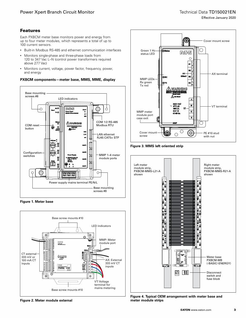
FeaturesEach PXBCM meter base monitors power and energy from up to four meter modules, which represents a total of up to 100 current sensors.• Built-in Modbus RS-485 and ethernet communication interfaces• Monitors single-phase and three-phase loads from
120 to 347 Vac L–N (control power transformers required above 277 Vac)
• Monitors current, voltage, power factor, frequency, power, and energy
PXBCM components—meter base, MMS, MME, display
Base mounting screws #8
LED indicators
COM reset button
COM 1/2 RS-485Modbus RTU
LAN ethernet RJ45 CAT5+ STP
MMP 1–4 meter module ports
Base mounting screws #8
Power supply mains terminal PE/N/L
Configuration switches
Figure 1. Meter base
Base screw mounts #10
LED indicators
CT external333 mV or 100 mA CT inputs
Base screw mounts #10
MMP: Meter module port
AX: External 333 mV CT inputs
VT: Voltage terminal for mains metering
Figure 2. Meter module external
Cover mount screw
AX terminal
MMP LEDsRx greenTx red
VT terminal
PE #10 studwith nut
Cover mount screw
MMP meter module port case exit
Green 1 Hzstatus LED
Figure 3. MMS left oriented strip
Right meter module strip, PXBCM-MMS-R21-Ashown
Left meter module strip, PXBCM-MMS-L21-Ashown
Meter base PXBCM-MB(-BASIC/-ENERGY)
Disconnect switch and fuse block
Figure 4. Typical OEM arrangement with meter base and meter module strips

4
Technical Data TD150021ENEffective January 2020
Power Xpert Branch Circuit Monitor
EATON www.eaton.com
Approved panel with one or more PXBCM-MMEs mounted. May also be housed with the PXBCM-MB.
PXBCM-CBL nn cable
Disconnect swtich and fuse block
Approved panel with PXBCM-MB and PXBCM-MMs
Existing panel with branch circuits monitored by external CTs
Figure 5. Hybrid system—retrofit of external meter module in existing panelboard tied to meter base in OEM panelboard with meter module strips
Dimensions
4.119
6.691
Figure 6. Meter base mounting dimensions

5
Technical Data TD150021ENEffective January 2020
Power Xpert Branch Circuit Monitor
EATON www.eaton.com
Made in Mexico
SN: YYMMDDkXXXXXStyle No. 66D2312G01Cat. No. PXBCM-MMS-L09
Rev. XFW VX.X
1.37 (3.48)
5.85 (14.86)
2.96 (7.52)
11.00 (27.94)
15.00 (38.1)
2.53 (6.43)
2.83 (7.19)
1.31(3.33)
16.93 (43.0)
Made in Mexico
SN: YYMMDDkXXXXXStyle No. 66D2313G01Cat. No. PXBCM-MMS-L15
Rev. XFW VX.X
17.00 (43.18)
21.00 (53.34)
22.93 (58.24)
1.37 (3.48)
Made in Mexico
SN: YYMMDDkXXXXXStyle No. 66D2314G01Cat. No. PXBCM-MMS-L21
Rev. XFW VX.X
23.00 (58.42)
27.00 (68.58)
28.93 (73.48)
1.37 (3.48)
5.85 (14.86)
2.96 (7.52)
2.53 (6.43)
2.83 (7.19)
1.31(3.33)
5.85 (14.86)
2.96 (7.52)
2.53 (6.43)
2.83 (7.19)
1.31(3.33)
Figure 7. MMS mounting dimensions in inches (cm)
6
Technical Data TD150021ENEffective January 2020
Power Xpert Branch Circuit Monitor
EATON www.eaton.com
7.700
6.9258.525
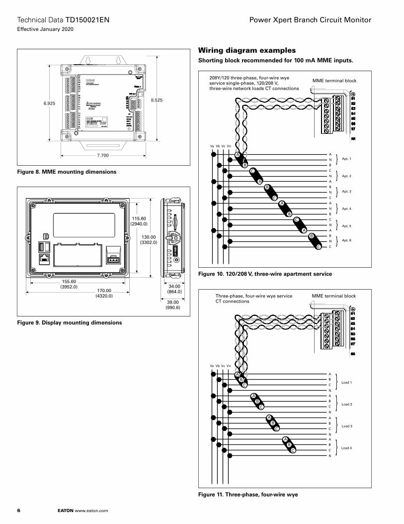
Figure 8. MME mounting dimensions
155.60(3952.0)
170.00(4320.0)
34.00(864.0)
39.00(990.6)
115.60(2940.0)
130.00(3302.0)
Figure 9. Display mounting dimensions
Wiring diagram examplesShorting block recommended for 100 mA MME inputs.
Va Vb Vc Vn
A
C
N
B
N
A
B
N
C
C
N
B
A
N
N
A
C
B
}}}}}}
Apt. 1
Apt. 2
Apt. 3
Apt. 4
Apt. 5
Apt. 6
A
B
C
AB
CA
BC
AB
C
208Y/120 three-phase, four-wire wye service single-phase, 120/208 V, three-wire network loads CT connections
MME terminal block
Figure 10. 120/208 V, three-wire apartment service
Va Vb Vc Vn
AB
C
AB
C
Three-phase, four-wire wye serviceCT connections
AB
C
AB
C
A
C
N
B
}
Load 1
A
C
N
B
A
C
N
B
A
C
N
B
}}}
Load 2
Load 3
Load 4
MME terminal block
Figure 11. Three-phase, four-wire wye

7
Technical Data TD150021ENEffective January 2020
Power Xpert Branch Circuit Monitor
EATON www.eaton.com
Va Vb Vc Vn
C
A}}
C
A
B
N Apt. 1
B
C
N
C
Apt. 2
AB
C
AB
C
Three-phase, four-wire wye serviceCT connections with three-phase, four-wire and apartment loads
AB
C
AB
C
A
C
N
B
}
Load 1
A
C
N
B
A
C
N
B
A
C
N
B
}}}
Load 2
Load 3
Load 4
MME terminal block
Figure 12. Three-phase, four-wire wye
Figure 10, Figure 11, and Figure 12 are representative of wiring configurations that can be used with the PXBCM. Table 2 shows the supported service voltage system types and corresponding meter load options.
Table 2. Service voltage systemService voltage system type Virtual meter load options
Three-phase, four-wire wye Three-phase, four-wire wyeThree-phase, three-wire delta120/208 three-wire apartmentSingle-phase, two-wire
Three-phase, three-wire delta Three-phase, three-wire deltaThree-phase, four-wire delta Three-phase, three-wire delta
Single-phase, two-wireSingle-phase, three-wire
Single-phase, three-wire Single-phase, three-wireSingle-phase, two-wire
Single-phase, two-wire Single-phase, two-wire
Product specificationsPXBCM-MB(-BASIC/-ENERGY)
• Weight: 1 lb • W/H/D: 7.0 in (17.6 cm) / 6.3 in (15.8 cm) / 2.6 in (6.6 cm) • Each meter base can interface to 1–4 meter modules
(–MMS and/or –MME) • Housing: NEMAT 1, IP20 • Pollution degree 2 • Operational temperature range: –20 ºC to +70 ºC • Storage temperature range: –45 ºC to +85 ºC • Elevation: 0–3000 m up to 277 V L–N
Humidity: 5–95% noncondensing • Elevation: 0–2000 m up to 347 V L–N
Humidity: 5–95% noncondensing • Requires control power transformer
• ULT file no. E185559, UL standard UL61010-1 • CNL evaluation to CAN/C22.2 No. 1010.1.92 • CE mark • EMC EN61326–IEC61000-4-X level 3
• Emissions conducted and radiated as part of PXBCM system, FCC part 15 class B
• CISPR 11/22 class B
External circuit connections • COM1/2 RS-485 Modbus Slave RTU:
• 9600–115.2 K (default) baud
• –D, +D, Com/Shield
• Use RS-485 cable—4 K ≤19.2 Kb, 2 K
• LAN ethernet RJ45 CAT5 10/100BASE-T • Use STP Cat5+ for full EMC compliance
• MMP1-4 meter module ports: • 2 pair cable, 1 pair power, 2nd coms
• Use PXBCM-MMP-CBLnn—CBLEnn cables
• Each MMP is separately isolated
• Power supply mains 100–277 Vac L:N • ±10%, CAT III, 47–63 Hz, 6 W
• Double insulated
• 320 Vac surge filter clamp L:N, L:G, N:G—Do not high pot
• Provide external line fuse or breaker sized to protect wiring
• Three-position fixed terminal block 1/2/3 = PE/N/L, supporting 12 AWG (2.5 mm) wire

8
Technical Data TD150021ENEffective January 2020
Power Xpert Branch Circuit Monitor
EATON www.eaton.com
PXBCM-MMS
• Weight 09/15/21: 1.0/1.5/2.0 lb • Width: 1.4–3.0 in (3.5–7.5 cm)• Height 2.5 in (6.4 cm) • Length 09/15/21: 16.9/22.9/28.9 in (43/58.2/73.5 cm) • Housing NEMA 1, IP20, Pollution Degree 2 • Operational/storage temp.: –20 ºC to +70 ºC /–45 ºC to +85 ºC • Elevation: 0–3000 m up to 277 V L–N
Humidity: 5–95% noncondensing • Elevation: 0–2000 m up to 347 V L–N
Humidity: 5–95% noncondensing • Requires metering voltage transformers
• CE mark • Safety: IEC/EN/UL61010-1, UL file no. E185559, CNL evaluation
to CAN/C22.2 No. 1010.1.92 • EMC EN61326—IEC61000-4-X level 3 • Emissions conducted and radiated as part of PXBCM system—
FCC part 15 and CISPR 11/22 class B • MMP meter module ports—2x2 connector, 2 pair cable,
1 pair power, 2nd data coms
• Use PXBCM-MMP-CBLnn—CBLEnn cables
VT—Voltage terminal metering inputs • 47–63 Hz, CAT III, 5 Mohm input impedance A/B/C/N • Wye 277 Vac L:N(G) 480 V L:L maximum nominal rating • Floating delta, corner grounded delta, and high-impedance
wye not supported without the use of an interposing PT potential transformer
• Four-position fixed terminal block Va, Vb, Vc, Vn, • 24–12 AWG—ferrules recommended
• PE—protective earth grounding stud at base of MMS bracket— #8 stud
AX CT current terminal metering inputs • 333 mV secondary CT input to MMS at maximum external CT
primary rating • Primary load rating determined by external CT
• In-line terminal block 24–14 AWG ferrules recommended for stranded wire
PXBCM-MME
• Weight: 1 lb • W/H/D: 7.7 in (19.5 cm) / 8.5 in (21.6 cm) / 1.6 in (4.1 cm) • Housing NEMA 1, IP20, Pollution Degree 2 • Operational temperature range: –20 ºC to +70 ºC • Storage temperature range: –45 ºC to +85 ºC • Elevation: 0–3000 m up to 277 V L–N
Humidity: 5–95% noncondensing • Elevation: 0–2000 m up to 347 V L–N
Humidity: 5–95% noncondensing • Requires metering voltage transformers
• CE mark • UL file no. E185559, UL standard UL61010-1 • CNL evaluation to CAN/C22.2 No. 1010.1.92 • EMC EN61326—IEC61000-4-X level 3
• Emissions conducted and radiated as part of PXBCM system, FCC part 15 class B
• CISPR 11/22 class B
MMP meter module ports • 2 pair cable, 1 pair power, 2nd data coms • Use PXBCM-MMP-CBLnn—CBLEnn cables
VT—voltage terminal metering inputs • 47–63 Hz, CAT III, 5 Mohm input impedance • Wye 277 Vac L:N(G) 480 V L:L maximum nominal • Floating delta, corner grounded delta, and high-impedance
wye not supported without the use of an interposing PT potential transformer
• Five-position fixed terminal block Va, Vb, Vc, Vn, PE • 24–12 AWG—ferrules recommended
CT and AX CT current terminal metering inputs • 333 mV secondary CT input to MME at maximum external CT
primary rating • Primary load rating determined by external CT
• CT 21 and AX 4 pair dual tier terminal blocks • 24–12 AWG—ferrules recommended
Cables
• ~1-inch bend radius required • 600 V insulation rating • 105 °C temperature rating • UL 61010-1 • UL file no. E185559 • 2 twisted pair, PVC jacket 0.28 inches OD jacket

9
Technical Data TD150021ENEffective January 2020
Power Xpert Branch Circuit Monitor
EATON www.eaton.com
Product selection
Table 3. PXBCM component catalog numbersDescription Suffix description Catalog number Notes
Meter base Basic series PXBCM-MB-BASICMeter base Energy code series PXBCM-MB-ENERGYMeter module strip Left 9 CT PXBCM-MMS-L09-A A = 1-in pitch, 100 AMeter module strip Left 15 CT PXBCM-MMS-L15-A A = 1-in pitch, 100 AMeter module strip Left 21 CT PXBCM-MMS-L21-A A = 1-in pitch, 100 AMeter module strip Right 9 CT PXBCM-MMS-R09-A A = 1-in pitch, 100 AMeter module strip Right 15 CT PXBCM-MMS-R15-A A = 1-in pitch, 100 AMeter module strip Right 21 CT PXBCM-MMS-R21-A A = 1-in pitch, 100 AMeter module external 21+4 external 333 mV CT PXBCM-MME-X25-333MV X = external CTMeter module external 21 external 100 mA CT + 4 external 333 mV CT PXBCM-MME-X21-100MA X = external CTMeter module port cable Length 6 in PXBCM-MMP-CBL6I Meter module port cable Length 1 ft PXBCM-MMP-CBL01 Meter module port cable Length 2 ft PXBCM-MMP-CBL02 Meter module port cable Length 3 ft PXBCM-MMP-CBL03 Meter module port cable Length 4 ft PXBCM-MMP-CBL04 Meter module port cable Length 6 ft PXBCM-MMP-CBL06 Meter module port cable Length 8 ft PXBCM-MMP-CBL08 Meter module port cable Length 12 ft PXBCM-MMP-CBL12 Meter module port cable Length 16 ft PXBCM-MMP-CBL16 Meter module port cable Length 20 ft PXBCM-MMP-CBL20 Meter module port cable Length 28 ft PXBCM-MMP-CBL28 Meter module port cable ext. Length 8 ft PXBCM-MMP-CBLEX08 Meter module port cable ext. Length 16 ft PXBCM-MMP-CBLEX16 BCM local display 5.7-in diameter display PXBCM-DISP-6-XV BCM local display cable Replacement display cable PXBCM-DISP6XV-DAT
333 mV current sensor
Split-core 333 mV sensors can be connected to the four auxiliary current inputs on the BCM-MMS or BCM-MME as well as any of the 21 current inputs on the PXBCM-MME-X25-333MV. A variety of window sizes and ratios are available. Refer to TD121001EN for ordering information.
100 mA current sensor
100 mA current sensors can be connected to any of the 21 current inputs on the PXBCM-MME-X21-100MA. A selection of solid core 100 mA sensors are available through the Eaton catalog. Refer to TD150028EN for ordering information.

10
Technical Data TD150021ENEffective January 2020
Power Xpert Branch Circuit Monitor
EATON www.eaton.com

11
Technical Data TD150021ENEffective January 2020
Power Xpert Branch Circuit Monitor
EATON www.eaton.com

Eaton1000 Eaton BoulevardCleveland, OH 44122United StatesEaton.com
© 2019 EatonAll Rights ReservedPrinted in USAPublication No. TD150021EN / Z23537December 2019
Eaton is a registered trademark.
All other trademarks are property of their respective owners.
Power Xpert Branch Circuit Monitor
Technical Data TD150021ENEffective December 2019