Power Supply Report July 2002 - University of California...
52
PS Status Report R. D’Alessandro 1 Power Supply Report Power Supply Report • 3 page review of the system proposed • The delivered prototypes (a short history) • Prototype Qualification • System Test Setup (TIB) • First Results from the System Test
Transcript of Power Supply Report July 2002 - University of California...
PS Status ReportR. D’Alessandro
1
Power Supply Report Power Supply Report
• 3 page review of the system proposed• The delivered prototypes (a short history)• Prototype Qualification• System Test Setup (TIB)• First Results from the System Test
PS Status ReportR. D’Alessandro
2
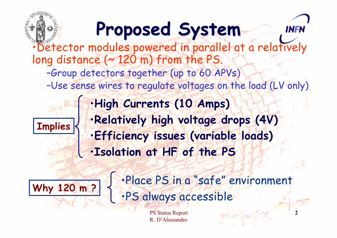
Proposed SystemProposed System•Detector modules powered in parallel at a relatively long distance (~ 120 m) from the PS.
–Group detectors together (up to 60 APVs) –Use sense wires to regulate voltages on the load (LV only)
Implies
•High Currents (10 Amps)•Relatively high voltage drops (4V)•Efficiency issues (variable loads)•Isolation at HF of the PS
Why 120 m ?•Place PS in a “safe” environment•PS always accessible

PS Status ReportR. D’Alessandro
3
PowerUnit
System ArchitectureSystem Architecture
PSM
•A PSM houses 2-4 PSUs and their control logic.•PSMs share the +48 V supplied by Power Units ( PU).•PSMs are grouped in crates (9-10 PSM/crate )•The PSM rack ( PSM array ) is driven by one dedicated Controller, which is interfaced to the CMS Slow Control
Controller

PS Status ReportR. D’Alessandro
4
The Prototype PSUThe Prototype PSU• PWM (Switching PS)
– (less power dissipation in the PSU)
• 2 HV generators– (extra flexibility for
detector biasing inside a given group)
• Relay switches– (disconnect the cable
from the PSU)• Low stray capacitance
transformers– Improve HF isolation

PS Status ReportR. D’Alessandro
5
Short History (1)Short History (1)• Project given the go ahead 20th April 2000• Prototypes ordered:
– October 2000 (CAEN), December 2000 (LABEN)• First release: (many iterations between Fi and manufacturers)
– June 2001 (CAEN), November 2001 (LABEN)• June 2001, Torino releases its test box• Prototypes returned to the manufacturers for
rework concerning isolation, stability, behavior during transients

PS Status ReportR. D’Alessandro
6
Short History (2)Short History (2)• CAEN prototype back at the
beginning of 2002, isolation improved plus other fixes
• Given to Torino for testing (plus debugging of the test box)
• April 2002, first results presented for CAEN (still some problems with transient behaviour)
• May 2002, CAEN modifies prototype (shorter response time plus “crow bar”), LABEN delivers its revised prototype.

PS Status ReportR. D’Alessandro
7
Old Slide (May 2002)Old Slide (May 2002)• LABEN prototype tested in Florence,
CAEN in Turin (an exact repeat of the testing sequence performed on the earlier version with the Turin test box)
• Both manufacturers readily answered queries and sent personnel to Turin and Florence to solve minor issues.The work done by both manufacturers is evident in the progress made both for what concerns the prototypes functionality and the over-voltage and over-current behaviour.

PS Status ReportR. D’Alessandro
8
Short History (3)Short History (3)• May 2002 LABEN takes prototype in Milan• June 2002, CAEN prototype back from
Torino• July 2002, LABEN prototype back from the
manufacturerIn the meanwhile in Florence we have:•developed various cable prototypes •developed ( help from Torino) a fast switched load•assembled and debugged the first all optical + CCU25, silicon module readout

PS Status ReportR. D’Alessandro
9
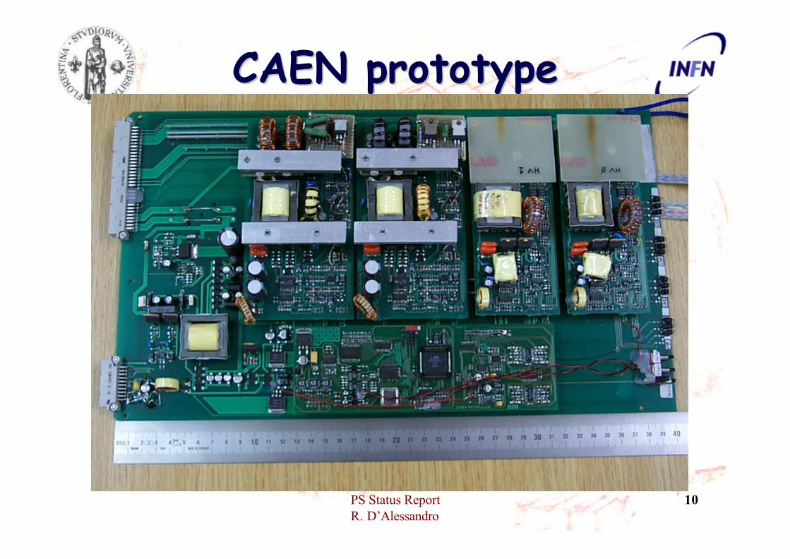
CAEN prototypeCAEN prototype• Based on existing SYxxxx solution• ONE PSU per board (2 boards delivered)
• Prototype at the level of an evaluation board• Software in good shape
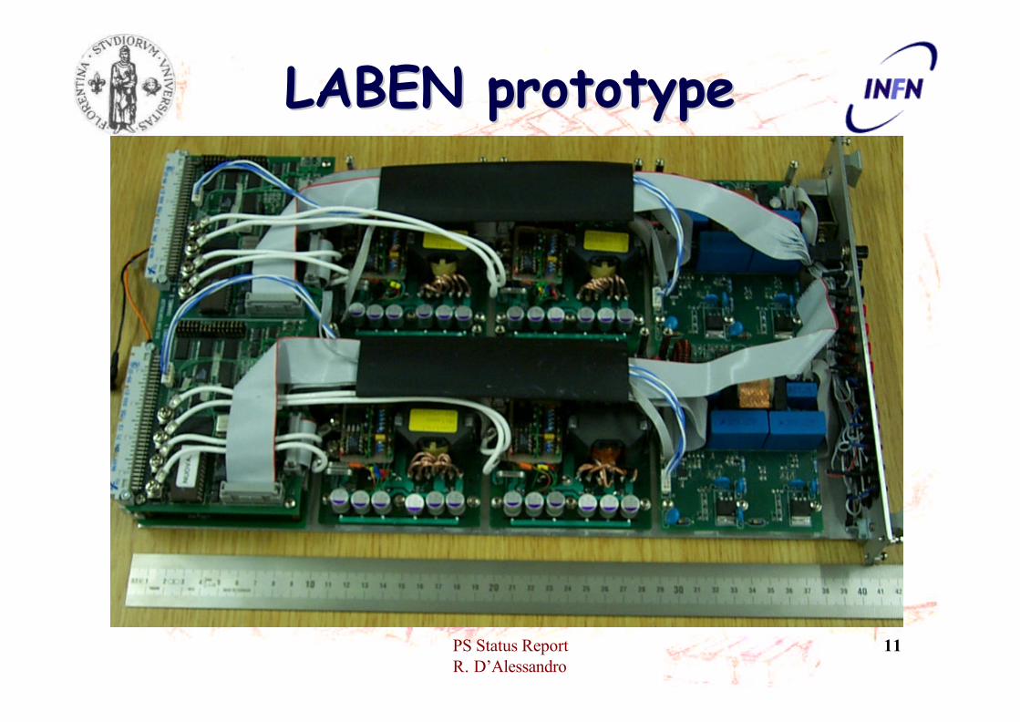
LABEN prototypeLABEN prototype• Developed from scratch• TWO PSUs per board (2 boards delivered)
• Prototype at “final” engineering stage• Software in its infancy (euphemistic)
PS Status ReportR. D’Alessandro
10
CAEN prototypeCAEN prototype
PS Status ReportR. D’Alessandro
11
LABEN prototypeLABEN prototype

PS Status ReportR. D’Alessandro
12
Qualification Qualification (the procedure)(the procedure)
• Use of “traditional” lab equipment• Gain an understanding of the measurement
complexities• Appraise the performance of the PS
prototypes• Subsequently use the Torino automated
test fixture for detailed repetitive and/or long term measurements

PS Status ReportR. D’Alessandro
13
Qualification Qualification (the hardware)(the hardware)
The basics:• Static loads• MOS switched loads• LCR meter(s)• Digital scope(s)• Cables
PS are floating ?• Careful screening• Well defined grounding• Differential measurements
Laben crate
CAEN crate

PS Status ReportR. D’Alessandro
14
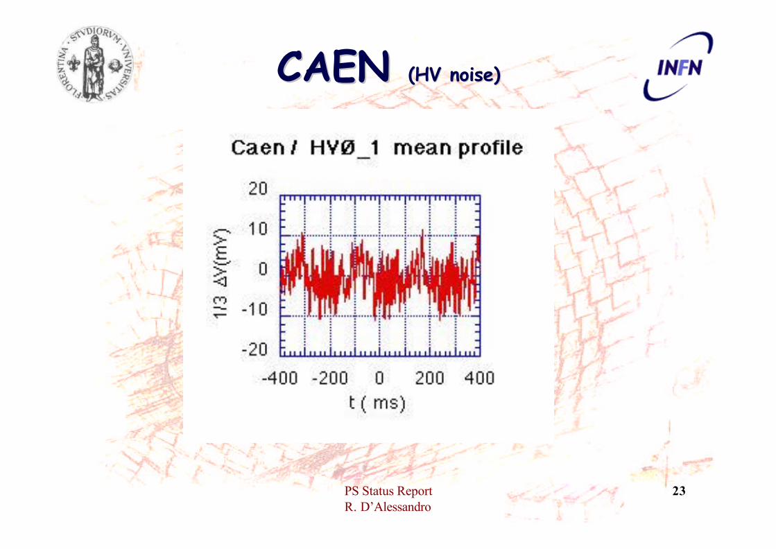
NOISE MeasurementsNOISE Measurements•BW < 20 MHz•Small capacitors 22 uF•Noise @ 6 Amps (2.5V) and 4 Amps (1.25V), depends very little on drawn current
•Measurements shown are with 50 metrecable (ext. 12 mm)
•Adding another 100 metre doesn’t change much (seems to have a beneficial effect)

PS Status ReportR. D’Alessandro
15
LABEN LABEN (LV Noise)(LV Noise)

PS Status ReportR. D’Alessandro
16
LABEN LABEN (HV noise)(HV noise)

PS Status ReportR. D’Alessandro
17
LABEN LABEN (Transients 1.25V)(Transients 1.25V)

PS Status ReportR. D’Alessandro
18
LABEN LABEN (Transients 2.5V)(Transients 2.5V)

PS Status ReportR. D’Alessandro
19
LABEN LABEN (Isolation)(Isolation)

PS Status ReportR. D’Alessandro
20
LABEN LABEN (comments)(comments)
• Stable behaviour (independent of load and cable length)
• Noise, is it acceptable ? (Especially HV)
• Transient behaviour generally very good (current limits, etc.); can the response time to voltage overshoots be bettered still ?
• Isolation is impressive, showing an understood capacitive behaviour
• Prototype designed with final engineering in mind
• Software not only a problem of looks, but essential parts (like trip and ramping procedures) missing. (A. Bocci in Florence is working on it)

PS Status ReportR. D’Alessandro
21
CAEN CAEN (LV noise, 2.5V)(LV noise, 2.5V)

PS Status ReportR. D’Alessandro
22
CAEN CAEN (LV noise, 1.25V)(LV noise, 1.25V)
PS Status ReportR. D’Alessandro
23
CAEN CAEN (HV noise)(HV noise)

PS Status ReportR. D’Alessandro
24
CAEN CAEN (Transients 1.25V)(Transients 1.25V)

PS Status ReportR. D’Alessandro
25
CAEN CAEN (Transients 2.5V)(Transients 2.5V)

PS Status ReportR. D’Alessandro
26
CAEN CAEN (Isolation)(Isolation)

PS Status ReportR. D’Alessandro
27
CAEN CAEN (comments)(comments)
• “Stable” behaviour (except for the 1.25V which is dependent of load and perhaps cable length, but can be fixed)
• Excellent Noise performance• Transient behaviour generally good (current
limits, etc.) there is an exception in a “pathological” condition.
• Isolation is good • Prototype designed as an evaluation board, not
clear how it will scale to engineering stage and how the presentperformance depends on the eval. Board arch.
• Software excellent, shows the great amount of work the company has put in general on PS systems.
PS Status ReportR. D’Alessandro
28
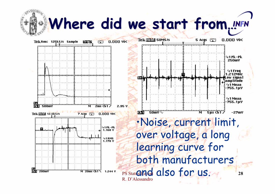
Where did we start from…Where did we start from…
•Noise, current limit, over voltage, a long learning curve for both manufacturers and also for us.

PS Status ReportR. D’Alessandro
29
General CommentsGeneral Comments• Prototype qualification is ONGOING• Results shown are the first, after the
definition of a systematic approach in order to have a reproducible set of measurements
• We will extend this approach to also include the Torino test box for repetitive and long term measurements
Both prototypes substantially answer our specifications as stated in the various documents we produced. Can they be used for the system test ? YES! (with caveats)
Above all the prototypes themselves need the system test in order to be further developed !

PS Status ReportR. D’Alessandro
30
TIB system testTIB system test• Not only for PS but “evolving” into a fully
fledged mechanical and electrical test– NEEDS optical decoupling to achieve
meaningful results• At first we needed a relatively good
understanding of an optical system compared to a copper one:– Many measurements made (Marco Meschini
talk, yesterday at the module test meeting)

PS Status ReportR. D’Alessandro
31
La La barabara
CCU25
DOH
Power distribution PCB

PS Status ReportR. D’Alessandro
32
La La barucciabaruccia

PS Status ReportR. D’Alessandro
33
From Marco’s talk (1)From Marco’s talk (1)• Front end APV25-s1 on FR4 hybrid, TIB
module, 300 um thick
12 way optoreceiver
3 Lasers A.O. Hybrid

PS Status ReportR. D’Alessandro
34Input/Output temporary connections on the back of module carrier
Final Kapton cable could be even shorter than this one
Short distance APV-AOH
From Marco’s talk (2)From Marco’s talk (2)

PS Status ReportR. D’Alessandro
35
What went insideWhat went inside• We placed a fixed resistor (5 Ohm value) on
both LV lines• Modules/Hybrids connected through TIST:
– Straight feed-through of the PS lines– CMOS buffering (same as used in final string)
• 47uF + 100nF blocking capacitors (per Module)• HV filter (specially for LABEN, but used also with CAEN)
PS Status ReportR. D’Alessandro
36
What went outsideWhat went outside
• Industrial PC dedicated to this test– two FEDs– one FEC– one TSC– one Digital Optical Transceiver– one Analog Optical Receiver
Plus a battery to supply 5 Volts to the Digital Opto-Hybrid and CCU ring !

PS Status ReportR. D’Alessandro
37
Software Software • “Standard” Module Test software (Lyon)• Modifications for :
– Laser driver (new version)– DOH, FEC – CCU 25
• The software works with two FEDs butcan only address one I2C channel at a time
•Allows direct comparison, with the module test suite

PS Status ReportR. D’Alessandro
38
Operating conditionsOperating conditions• Inverter out• MUX 100 Ohms (15 setting)• AOH, gain 3, bias 18 (new LDD!), 50 Ohm
termination• Standard M.Raymond parameters for the APV
• 50 metre “internal” + 100 metre “external” cable, which transports also sense wires and HV lines
• One common grounding point defined on the CCU ring (la bara is completely isolated from the “outside”)
• The PS are in another room

PS Status ReportR. D’Alessandro
39
Inverter effect Inverter effect (old CAEN L3)(old CAEN L3)
Inverter out
Inverter in

PS Status ReportR. D’Alessandro
40
The module and the The module and the hybrid survived !hybrid survived !
All measurements refer to a hybrid and a full TIB module triggered and read-out at the same time
ns
AD
C co
unts
CAEN 150m
TIB 09, 200V bias

PS Status ReportR. D’Alessandro
41
Common Mode with Common Mode with CAENCAEN TIB09
200 V biasHV filterDeconv
ADC channels
ADC channels
Peak

PS Status ReportR. D’Alessandro
42
Noise profile with CAENNoise profile with CAENTIB09,200 V biasHV filter
Deconv
APV strip
RMS/
stri
p
APV strip
RMS/
stri
p
Peak

PS Status ReportR. D’Alessandro
43
Common Mode with Common Mode with CAEN (2)CAEN (2) TIB09
200 V biasNO! HV filterDeconv
ADC channels
ADC channels
Peak

PS Status ReportR. D’Alessandro
44
Common Mode with Common Mode with LABENLABEN TIB09
200 V biasHV filterDeconv
ADC channels
ADC channels
Peak

PS Status ReportR. D’Alessandro
45
Common Mode with Common Mode with LABEN (2), Inverter INLABEN (2), Inverter IN
TIB09200 V biasHV filter
Deconv
ADC channels
ADC channels
Deconv
In case you weren’tconvinced !

PS Status ReportR. D’Alessandro
46
TIB09,200 V biasHV filter
Deconv
APV strip
RMS/
stri
p
APV strip
RMS/
stri
p
Noise profile with Noise profile with LABENLABEN
Peak

PS Status ReportR. D’Alessandro
47
APV strip
RMS/
stri
p
APV strip
Noise profile Hybrid Noise profile Hybrid CAEN CAEN -- LABENLABEN
CAEN
LABEN
RMS/
stri
p
The difference is the HV !
Deconvolution
PS Status ReportR. D’Alessandro
48
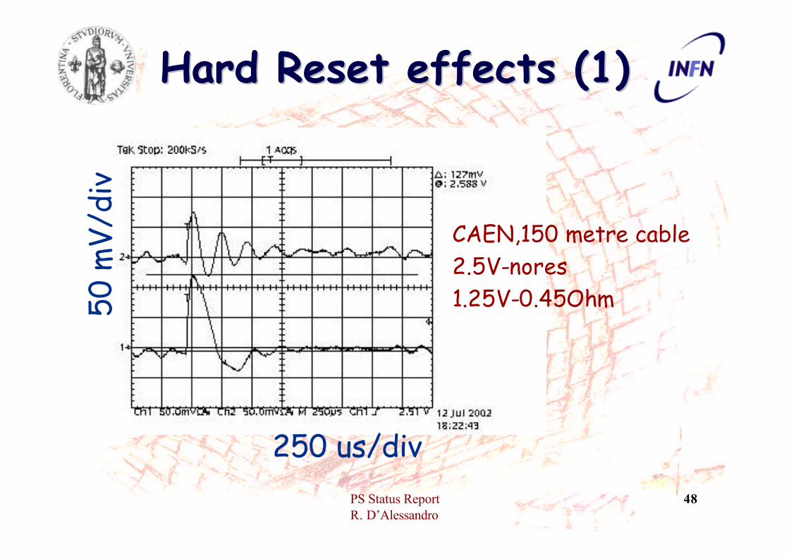
Hard Reset effects (1)Hard Reset effects (1)
CAEN,150 metre cable2.5V-nores1.25V-0.45Ohm
250 us/div
50 m
V/di
v

PS Status ReportR. D’Alessandro
49
Hard Reset effects (2)Hard Reset effects (2)
LABEN,150 metre2.5V & 1.25 noresistors
1 ms/div
1 ms/div
50 m
V/di
v
50 m
V/di
v
LABEN,150 metre2.5V & 1.25 5 Ohm

PS Status ReportR. D’Alessandro
50
ConclusionsConclusions• We have started !• PS work has given fruit to what we think
is a viable option for the Tracker (next months will give a definite answer)
• We will keep interacting with CAEN and LABEN to solve the remaining issues
• The DAQ is stable, (no glitches, no spurious hard resets !)
• Only two hybrids but ready to read-out up to 6 simultaneously
PS Status ReportR. D’Alessandro
51
Conclusions (2)Conclusions (2)This PS project is a collaboration between
Florence and TorinoThe TIB system test between
Florence and PisaThanks to a lot of people (a few names):
– CERN (J. Troska, F. Vasey, S. Marchioro, C.Paillard, L. Mirabito)
– Perugia (B. Checcucci, M. Brunetti)– Pisa (Roby Dell’Orso, R. Cecchi)– Torino (M. Costa, P. Trapani)
Thanks also to F. Maletta, M. Brianzi, E. Scarlini

PS Status ReportR. D’Alessandro
52
System Architecture (1)System Architecture (1)