Reflection properties of pressed polytetrafluoroethylene...
6
8.')6 J. Opt. Soc. Am.IVo!. 71. No. 7/Ju ly 1981 Reflection properties of pressed polytetrafluoroethylene powder Victor R. Weidner and Jack J. Hsia Rudiomet ric Physics Division, National Bureau af Stan dar ds, Washington, D.C. V. R. Weidner and J. J. Hsi Received December 18,1980; revised manuscript received February 12, 1981 The reflection properties of pressed polytetrafluoroethylene powder have been under investigation by the Radio- met ric Ph ysics Division at the National Bureau of S tanda rds for the past five years. This material has a great po- tential use, both as a sta ndard of diffuse reflectan ce and as a coating for integrating spheres for applications in re- flecta nce spectrophotometry and other signal-averaging devices. It possesses certa in physical and opt ical proper- ties t hat make it ideal for use in these applications. Techniques are given for preparing reflection standards and coating integrating spheres with the pressed powder. The effects of powder density and thickness on its reflec- tance are reported, and observations of possible problems with fluorescence th at are due to the presence of conta m- inants in the powder are discussed. The absolute reflectance (6°/hemispherical reflectance factor relative to a per- fect diffuser) is reported for the spectral range of 200- 2500 nm. T he directional/hemisph erical reflectance factor relat ive to 6°/hemispherical reflectance is given for several wavelengths in the ultraviolet and visible spectrum and for angle s of incidence bet ween 5 and 75°. T he bidirectio nal reflectance facto r is reporte d for 300, 600, and 1500 nm at angles of incidence of - 10,- 30, -50, and - 70° and at viewing angles at 10° intervals from - 80 to + 80° . INTROD U CTIO N T he reflection properties of pre ssed polyte tr afluoroethylene (PTFE) powder! in the ultr aviolet, visible, and near-infrared spectral regions, combined with certa in desirable physical characteristics, make this material exceptionally useful when the re is a need for a good white diffuser or a stan dard of diffuse reflectance. T he diffuse reflectance of pressed PTFE powder is remark ably high over the spect ral ran ge of 200-2500 nm and is probably higher than that of any other known mate rial , its reflecta nce being 99% or higher over the spectral range of 350- 1800 nm. It is particularly useful as a coati ng for inte - grating spheres commonly used in diffuse reflectance spec- trop hotomet ry. Historically, the most commonly used ma- terials for this purp ose have been magnesium oxide and bar- ium sulfate powders or bari um sulfate paint.? Much has been written on the opt ical properties of these materials, and the adva ntages and disadvanta ges of their use in spectrophoto- met ric applications have been experienced by nearly everyone involved with reflectance spectrophotometry. Certai nly, the re is no longer any advantage in coati ng integrating spheres by the old met hod of burn ing magnesium and collecting the magnesiu m oxide smoke. Thes tandards t hat still specify th at reflectance measureme nts be reported on a photometric scale relative to smoked magnesium oxide should be rewritten to specify that reflectan ce measur em ents be reported on an ab- solute reflectance scale (relative to a p erfect diffuser-'). A review of publications on properties and reflection values of materia l reflection standards is given in Ref. 2. T he purp ose of thi s pa per is to make available the techn ical findings of several years of research on the opt ical properties of pr essed PTFE powde r. Other a ut hors" have rep orted on the pot ent ial usefulness of this material as a reflection stan- da rd . The spectrophotometry group of the Radiometric Physics Division at the National Bureau of Sta nda rds (NBS) began studies of the reflection properties of pressed PT powder in 1975. At t hat time, this gr oup was engaged in co struc ting a new reference spectrophotometer for diffuse r flect an ce" along with a nu mber of accessory devices for me suring diffuse reflec tan ce. T hese accessory devi ces includ integrati ng spheres for measuring 6° /hemisp heri cal reflee ta nce factor, 45 % ° refle ctan ce factor, and direction hemispherical reflectance factor and a specular reflectome ter. At the same time , a more accurate absolute diffuse reflectanc scale was being established by the auxiliary sphere or Van d Akker method." A te chnique was developed for coating i teg rat ing spheres with the PTFE powder, and extensi meas urements of the optical properties of this material we carried out over a five-year period. The results of the studies are reported here along with some descriptive detai of the techniques used in preparing reflection sta ndards fro PTFE powder and its application to integr atin g spheres. PREPARATION T he PTFE powder is somewh at lumpy as it comes in a shi pi ng drum. It can be prep ared for optical-coating purpos by reducing it to a uniform low-density powder. T his can accomplished with a blender or other cho pping device, pref erably one with stainless-steel blad es and a glass conta in er The powder should be kept in glass contai ners and handl with tools made of mat erials such as sta inless steel t hat less likel y to contamina te the material. T he powder will a here to itself on pressing, but it does not adhere well to me glass, or plastic. One technique for making it adhere to me (or other materials) is fi rst to coat the metal with a thin fil of high-vacuum silicone grease. Once this is done, the powd can be pressed into place in thickness es varyin g from 1 to 1 mm with out much diffi culty. Th e silicone grease has a 10 volat ility and does not affect the reflection pro perties of t
Transcript of Reflection properties of pressed polytetrafluoroethylene...
8.')6 J. Opt. Soc. Am.IVo!. 71. No. 7/July 1981
Reflection properties of pressedpolytetrafluoroethylene powder
Victor R. Weidner and Jack J. Hsia
Rudiomet ric Physics Division, National Burea u af Stan dards, Washing ton , D.C.
V. R. Weidner and J . J . Hsi
Received Decemb er 18,1980 ; revised man uscript received February 12, 1981
T he reflection propert ies of pressed polytetrafluoroethylene powder have been under investigation by the Radiomet ric Ph ysics Division at the Nati onal Bureau of Standards for the past five years. T his mate rial has a great potent ial use, both as a sta ndard of diffu se reflectan ce and as a coating for integrating spheres for applications in reflecta nce spect rophotomet ry and ot her signal-averaging devices. It possesses certa in physical and opt ical proper t ies that make it idea l for use in these application s. Techniques are given for prepar ing reflection standards andcoating integrating spheres with the pressed powder. The effects of powder density and thickness on its reflectance are reported, and observat ions of possible problems with fluorescence th at are du e to the presence of conta minants in the powder are discussed . The absolute reflectan ce (6°/hemispherical reflectance factor relat ive to a per fect diffu ser) is reported for the spectral range of 200- 2500 nm. T he directional/h emisph erical reflectan ce facto rrelat ive to 6°/hemispherical reflectance is given for several wavelengths in the ultr aviolet and visible spectrum andfor angles of incidence bet ween 5 and 75°. T he bidirectio nal reflectance facto r is reporte d for 300, 600, and 1500nm at angles of incidence of - 10, - 30, -50, and - 70° and at viewing angles at 10° intervals from - 80 to + 80° .
INTROD UCTION
T he reflect ion proper t ies of pressed polyte trafluoroeth ylen e(PTFE) powder! in the ultraviolet, visible, and near-inf raredspectral regions, combined with certain desirable physicalcharacte ristics, make thi s material exceptionally useful whenthere is a need for a good white diffuser or a standard of diffusereflectance. T he diffuse reflectance of pressed PTFE powderis remark ably high over the spect ral ran ge of 200-2500 nm andis probabl y highe r than that of any other known material , itsreflectance being 99% or higher over the spect ral range of350- 1800 nm. It is par t icu larl y useful as a coati ng for inte grating spheres commonly used in diffu se reflectance spect rophotometry . Histori cally, the most commonly used materials for this purpose have been magne sium oxide and barium sulfate powders or bari um sulfate paint.? Much has beenwritten on the optical pr oper ti es of these materials, and theadvantages and disad van ta ges of their use in spect rophotomet ric applicat ions have been experienced by nearly everyoneinvolved wit h reflectan ce spectrophoto met ry. Certai n ly,the re is no longer any advantage in coati ng integrating spheresby the old method of burning magnesium and collecting themagnesiu m oxide smoke. The standards that still specify th atreflecta nce measurements be reported on a phot ometric scalere lative to smo ked magnesium oxide should be rewritt en tospecify that reflectan ce measur ements be reported on an absolute reflectance scale (relative to a perfect d iffuser-'). Areview of publi cations on properties and reflection values ofmaterial reflection standards is given in Ref. 2.
T he purp ose of thi s paper is to make available the techn icalfindings of several years of research on the optical propert iesof pr essed PTFE powde r. Othe r authors" have rep orted onthe potential usefulness of this materi al as a reflection standa rd . The spectrophotomet ry grou p of the Rad iometricPhysics Division at the National Bureau of Standards (NBS)
began studies of the refle cti on propertie s of pressed PTpowder in 1975. At that time, this group was engaged in cost ruc t ing a new reference spectrophoto meter for diffuse rflect an ce" along with a nu mber of accessory devices for mesuring diffuse reflec tance. T hese accessory devi ces includintegrating spheres for mea suring 6°/hemispheri cal refleetance facto r, 45% ° refle ctance facto r, and di rectionhemispherical reflectance factor and a specular reflectome ter.At the same time , a more accurate absolute diffuse reflectancscale was being established by the auxiliary sphere or Van dAkker method." A technique was develope d for coating itegrating spheres with the PTFE powde r, and exte nsimeasurements of the optical proper ties of this materi al wecarried out over a five-yea r peri od . T he results of thestudies are repor ted here along with some descr ipt ive detaiof the techniques used in preparing reflect ion standards froPTFE powder and its application to integrating spheres.
PREPARATION
T he PTFE powder is somewhat lumpy as it comes in a shipi ng drum. It can be prepared for optical-coating purposby reducing it to a uniform low-density powder. T his canaccomplished with a blender or othe r cho pping device, prefera bly one with stainless-ste el blades and a glass containerT he powder should be kept in glass containe rs and handlwith too ls mad e of materials such as stainless steel thatless likel y to contamina te the material. T he powder will ahere to itself on pressing, bu t it does not adhere well to meglass, or plastic. One technique for makin g it adhere to me(or ot he r ma terials) is first to coat the metal with a thin filof high-vacuum silicone grease. Once this is done, the powdcan be pressed into place in thickness es varyin g from 1 to 1mm without mu ch diffi culty. The silicone grease has a 10volatility and does not affect the reflection pro perties of t

V. R. Weidner and J . J . Hsia Vol. 71. No. 7/J uly 1981/J . Opt. Soc. Am, 857
1. 0 0 5,r------------,
PTFE POWDER
,\
'+\\
\,\
• 300 to 180 0 nm \(overage of 10 wave- \
lengths).2000nm \
(averoge of 2 runs)
1.0 00
O.980,L.---J._-'-_.L...-----L-=--...........__=_'
0 .5
0 .985
1.0 1.5 2 .0DENSITY (o/cm3 )
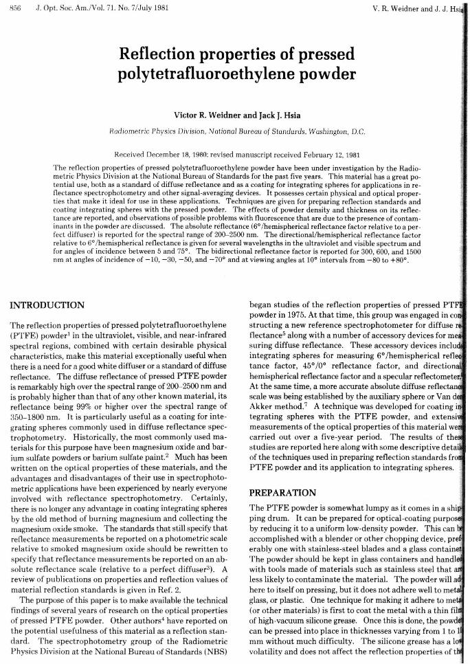
Fig. 2. Pressed PTFE powder reflectan ce as a fun ction of powde rden sity (lO-mm t hickness) .
Th e reflectance of PTFE powder is influenced by th e densityto which the powder is pressed. Th is relat ionship is illustrated in Fig. 2, in which the results of a number of measurements of reflectan ce versus powder density are plotted. Thereflectance scale in thi s illustr at ion is a relativ e one with theda ta normalized at a density of 1.0 g/cm-', because this is thedensity at which the powder reflectance is the highest. Thereseem to be no noticeable wavelength -related effects forwavelengths less than 2000 nm. T he vertical bars in Fig. 2show the spread in reflectance values at th e 10 selected
DENSITY
order to master the coat ing techniques. T he powder shouldbe packed in lightly at first, to a dept h of approximat ely 2-3times the desired final th ickness before it is pressed to a finish.T he application of added powder to an already hard -pressedcoating may result in a peeling and separation of the materialinto layers. The best results are obta ined with a sand-blastedor ground-glass pressi ng tool, such as a round -bottom flaskof small diameter. The coating should be done in a relat ivelyclean, du st-free environment because the PTFE coat ingusually becomes electrostatically charged during the pressingand will hold small specks of dirt or lint. T hese can be pickedup or removed with a small, clean art ist 's brush .
PTFE powder is very fine and easily mixes in the air aboutthe working area. Alth ough the powder is believed to benontoxic, it is a good practice to use a dust mask to avoid un necessary breath ing of the material.
PTFE may form toxic gases at thermal decomp ositiontemperat ures above 400° C. T hese toxic products may beprodu ced inadverten tly by contact of the fine powder with aflame or other high-temperature source. For further infor mation on the safe handli ng of fluorocarb on resins, refer toRef. 8.
It should be noted th at there are U.S. patents dealing withthe use of fluorocarb ons as coatings for integ rating spheres.Th ese U.S. patents are given in Ref. 9.
PTFE powder because it contacts only a thin layer at t hepowder-metal interface.
PTFE powder has been successfully applied to integratingspheres ranging in diameter from a few cent imete rs to 45 cmand to large, flat sur faces used as reflection standards. T hecoatings are not affected by conditions of high humidity because the pre ssed powder repels water. Exposur e to highintensity ultraviolet radiation," such as that encountered nearuenon arc, will slightly degrade the reflection propert ies of
, :the coatings in the ultraviolet spectral region. The reflectancewill be degraded as a resul t of contaminat ion from smoke,dust, or other contamina nts that may be present.
The time required for coating an integ rating sphere ofllO-cm diameter with a 6-mm-thick coating is typically about
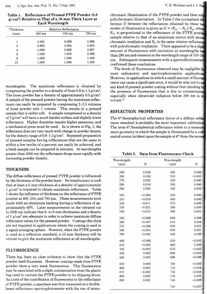
'. h. Thi s includes prepa ring th e PTFE powder with ablender, t rimming up the finished coat ing around the ports,IIId assembly of the usual two hemispheres. At NBS, spheresupto 45-cm diameter are coated with the aid of a specialb!tnj~phere manipulator (Fig. 1) tha t enables the techniciantorotate and pivot the hemisph ere about the cente r point ofthe sphere and pack the PTFE powder into the curva ture ofthe hemisph ere with a light pressure, using hand tools such18 a stainless stee l spoon or a round-bottom glass flask. In8OI1le special application s, such as in th e preparation of anIllliliary sphere for determining the absolute reflectance ofthe sphere coating, the rad ius of curvature of the coati nglUrface is carefully controlled by tamping the PTFE powderlIDder an electronic tamping head before it is rolled to a finalilniah. A retainer ring is attached to th e hemisph ere flange4uring the coating procedur e to retain the powder at the open
ofthe hemisph ere. When the coating is completed, this'ning ring is removed, and the two completed hemispheresattached to each other by means of th e flanges. T he
. E coating expands slightl y at the hemisphere edge when11 ~reta ining ring is removed. This is an advantage because
atesults in the formati on of a t ight fit when th e two herni~res are combined to form th e sphere.
; 8 Aa with any sphere-coat ing material, PTFE powder has itsof Idvantal!'es and disadvantaz es. Some pra ctice is requ ired in
Fig.1. The NBS integrating-sphere-coat ing apparatus showing th ehemisphere manipulator with the electronica lly cont rolled tamping'bl!ad used to pr ess the PT FE powder into the hemisph ere with auniform radiu s.
858 J. Opt. Soc. Am.N o!. 71. No. 7/July 1981 V. R. Weidner and J. J . Hs
Table 2. Da ta fr om Fluorescence Check
Wavelength Wavelength(nrn) D (nrn) D
250 0.019 500 0.000260 0.016 510 -0.002270 0.022 520 0.000280 0.Ql8 530 0.000290 0.005 540 0.002
300 - 0.004 550 0.000310 - 0.Ql8 560 0.000320 - 0.011 570 0.000330 - 0.021 580 0.005340 -0.015 590 0.001
350 - 0.009 600 0.006360 -0.007 610 0.004370 - 0.006 620 0.001 .380 -0.003 630 0.001390 -0.002 640 0.000
400 - 0.006 650 -0.002410 - 0.002 660 0.000420 - 0.002 670 - 0.002430 0.002 680 - 0.002440 0.002 690 -0.006
450 0.000 700 - 0.003460 0.002 710 - 0.004470 -0.002 720 - 0.003480 0.002 730 0.002490 0.002 740 -0.008
750 - 0.007
REFLECTION PROPERTIES
The 6°/hemispherical reflectance factor of a diffuse refltance standard is probably the most imp ortan t calibratioThe term 6°/h emispherical reflectan ce refers to a measurment geomet ry in which the sample is illuminated by a colmated source incident upon the sample at 6° from th e norm
chromatic illum ina tion of the PTFE powder and then wipolychr omatic illumination. In Table 2 the norm alized diference D between the reflectances obtai ned by these tmodes of illumination is given as D = (Rm - Rp)!Rp, wheRm is proportional to the reflectance of the PTFE powdsample relative to that of an aluminum mir ror with monchromat ic irradiation and Rp is the same relative reflectanwith polychromati c irradia tion. There appeared to be a sligamount of fluorescence with excitation at wavelength s Ithan 290 nm and emission in the wavelength range of 310-3nm. Subsequent measurements with a spectrofluorometerconfirmed these conclusions.
T he levels of fluorescence observed may be negligible fmost rad iometric and spect rophoto metric applicatioHowever , in applications in which a small amount of fluorcence can cause a significant error , it would be wise not toany kind of pressed-powder coat ing with out first checking fthe presence of fluorescence that is due to contaminanespec ially when ultraviolet radiation below 300 nm is ivolved.! '
Thickness Relative Reflectance(rnm) 400nm 550 nm 700 nm
1 0.991 0.989 0.9862 0.995 0.994 0.9934 0.998 0.998 0.9976 1.000 1.000 0.9998 1.000 1.000 1.000
10 1.000 1.000 1.000
FLUORESCENCE
The diffuse reflectan ce of pressed PTFE powder is influencedby the thickness of the powder layer . Its translucency is suchthat at least a 6-mm thickness at a density of approximately1 g/cm'' is required to obtain maximum reflectance. Table1 shows the influence of thickness on the reflectance of PTFEpowder at 400, 550, and 700 nm. These measurements weremade wit h an aluminum backing having a reflectance of approximately 60%. Later measurements in the infrared outto 2500 nm indicate that 6- to 8-mm thicknesses and a densityof 1 g/cm'' are adequate in order to achieve maximum diffusereflectanc e values for the pressed powder. Coatings this thickare not required in applications where the coating is used ina signal-averaging sphere. However, when the PTFE powderis used as a reflection standa rd , a 10-mm thickness will becertain to give the maximum reflectance at all wavelengths.
THICKNESS
Table 1. Reflectance of Pres sed PTFE Powd er (0.8g/cm3 ) Relative to T hat of a lO-mm-Thick Layer at
Each Wavelength
wavelengths. The maximum reflec tance is obtained bycompressing the powder to a density of from 0.8 to 1.2 g/cm''.T he loose powder has a density of approximately 0.5 g/cm''.A sample of the pres sed powder having the maximum reflecta nce can easily be prepared by compressing 2-2.5 volumesof loose powder into 1 volume. This resul ts in a pressedsample that is rather soft. A sample compressed to a densityof 2 g/cm" will have a much harder surface and slightly lowerreflectance. Higher den sities require higher pressures, anda mechani cal press must be used . As is shown in Fig. 2, thereflectan ce does not vary much with change in powder densityfor the density range of 0.8-1. 2 g/cm '', Repeated preparationof pressed samples having reflectances that are the same towithin a few tenths of a per cent can easily be ach ieved , anda fresh sample can be prepared in minutes. At wavelengthsgreater than 2000 nm the reflectance dr ops more rapidly withincreasing powder den sity.
T here has been no clear evidence to show that the PTFEpowder itself fluoresces. However, coatings made from PTFEpowder show a very weak fluorescence. This fluorescencemay be associated with a slight contamination from the plasticbag used to contain the PTFE powder in its shipping drum.As a test of the cont ribution of fluorescence to th e reflectanceof PTFE powder, a specimen was first measured on a doublebeam reflectance spect rophotometer with the use of mono-
IOO'..----r- - -...- --T'"---r-- --,
96 6°/HEM ISPHERICAL REFLECTANCEOF
PT FEPOWDER
9 9
E~ 9 8zt:!(,)w~ 97wa::
95 L-...J.__~__.L...._""""__-'200 500 10 00 1500 2000 2500
WAVELENGTH (NM)
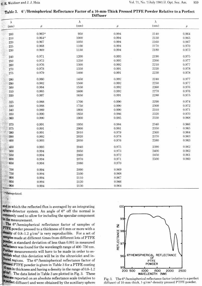
Fig. 3. T he 6° /h emisph erical reflectance factor (relat ive to a perfectdiffuser ) of 10-mm -thick, I -g/cm't-density pressed PTF E powder .
and in which the reflected flux is averaged by an integ ratinghere-detector system. An angle of 6° off the normal is
t'OInmonly used to allow for including the specular componentIn the measurement.
The 6°/hemispherical reflectance factor of samples ofP1'FE powder pre ssed to a thickness of 6 mm or more with a
'ty of 0.8-1.2 g/cm'' is very reproducible. For a set of- pIe)! made at differen t t imes from different lots of PT FE~er. a standard deviat ion of less than 0.001 in measured
ce was found for the wavelength range of 400-750 nm.~r measurements will have to be made in order to esr-_~ ~ what this deviati on will be in the ultraviolet and in" veQ regions. The 6°/hemispherical reflectance factor of
PTFE powder is given in Table 3 for a PTFE coatingIllInin thickness and having a density in the range of 0.8-1.2
ClIl3. The data listed in Table 3 are plotted in Fig. 3. Theseare reported on an absolute reflectance scale (relative to
Peifect diffuser) and were obtained by the auxiliary sphere
:v.R.Weidner and J . J. Hsia Vol. 71, No. 7/J uly 1981/J . Op t . Soc. Am. 859
Table 3. 6°/Hemispherical Reflectance Factor of a lO-mm-Thick Pressed PTFE Powder Relative to a P erfectDiffuser
A A A(nm ) p (nrn) p (rim) p
200 0.962° 950 0.994 2140 0.964
210 0.964° 1000 0.994 2150 0.965
220 0.967 1050 0.994 2160 0.967
225 0.968 1100 0.994 2170 0.970
230 0.969 1150 0.994 2180 0.973
240 0.971 1200 0.993 2190 0.975
250 0.973 1250 0.993 2200 0.977
260 0.976 1300 0.992 2210 0.977
270 0.978 1350 0.991 2220 0.978
275 0.979 1400 0.991 2230 0.978
280 0.980 1450 0.992 2240 0.977
290 0.982 1500 0.992 2250 0.977300 0.984 1550 0.992 2260 0.976
310 0.985 1600 0.992 2270 0.976. 320 0.987 1650 0.991 2280 0.975
325 0.988 1700 0.990 2290 0.974
330 0.988 1750 0.990 2300 0.972
340 0.989 1800 0.990 2310 0.971
350 0.990 1850 0.986 2320 0.970
360 0.990 1900 0.985 2330 0.968
370 0.991 1950 0.984 2340 0.966375 0.991 2000 0.981 2350 0.965380 0.991 2010 0.979 2360 0.964390 0.992 2020 0.978 2370 0.963400 0.993 2030 0.976 2380 0.963
450 0.993 2040 0.975 2390 0.962
500 0.994 2050 0.973 2400 0.962550 0.994 2060 0.972 2450 0.961600 0.994 2070 0.971 2500 0.960650 0.994 2080 0.970
0.994 2090 0.9690.994 2100 0.9680.994 2110 0.9670.994 2120 0.9660.994 2130 0.964
860 ,J. Opt. Soc. Am.IVol. 71. No. 7/July 1981 V. R. Weidner and J. ,J. Hsia
Table 4. Direc t iona l/Hemispherical Reflectance Factor of P r essed PTF E Powde r fo r a IO-mm-Thick Coating(Re lative to Hem ispherical Reflec tance at 6° Incide nce)
Angleof Reflectance
Incidence 250nm 300 nm :350 nm 450nm 600 nm 750 nm
6° 1.0000 1.0000 1.0000 1.0000 1.0000 1.000010° 1.0003 1.0002 1.0001 1.0001 1.0001 1.000115° 1.0009 1.0005 1.0004 1.0002 1.0002 1.000220° 1.0017 1.0010 1.0007 1.0004 1.0004 1.000425° 1.0026 1.0015 1.0011 1.0007 1.0006 1.000630° 1.0038 1.0022 1.0015 1.0010 1.0008 1.000835° 1.0052 1.0030 1.0021 1.0013 1.0011 1.001140° 1.0066 1.0038 1.0026 1.0016 1.0014 1.001445° 1.0082 1.0047 1.0032 1.0020 1.0017 1.001750° 1.0099 1.0056 1.0038 1.0023 1.0020 1.002055° 1.0117 1.0065 1.0044 1.0026 1.0023 1.002360° 1.0134 1.0074 1.0049 1.0029 1.0025 1.002565° 1.0153 1.0083 1.0054 1.0031 1.0027 1.002770° 1.0170 1.0090 1.0058 1.0032 1.0028 1.002975° 1.0186 1.0097 1.0061 1.0032 1.0029 1.0029
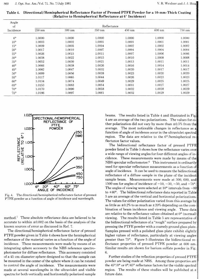
Fig. 4. The directional/hemispherical reflectance factor of pressedPTFE powder as a function of angle of incidence and wavelength.
1.025r---- --- - ----,DIRECTIONAL/HEMISPHERICAL
REFLECTANCE OFPTFE
1.020 POWDER
method." T hese absolute reflectance data ar e believed to beaccurate to wit hin ± 0.002 on t he basis of the analysis of thekn own sources of error as discussed in Ref. 7.
The direct ional/hemispherical reflectance factor of pressedPTFE powder given in T abl e 4 shows how the hemi sphericalreflecta nce of the material varies as a fun ct ion of the angle ofincidence. These measurements were made by mean s of anintegrating sphere accessory to the NBS refer ence spectrophotometer for d iffuse reflectance. This accesso ry consistedof a 45-cm-d iame te r sphere designed so tha t the sample canbe mounted in the center of the sphere where it can be rotatedto cont rol t he angle of incidence . The measurem ents weremade at several wavelengths in the ultraviolet and visiblespect ra for both vert ica lly and hor izon tally polari zed sample
beams . The results list ed in T abl e 4 and illus tr ated in Fig.4 are an average of th e two polarizati ons. The valu es for eit her polarization did not vary by more than ± 0.5% from theave rage. T he most noti ceabl e changes in reflectan ce as afunction of angle of incidence occur in the ultraviolet spect ralregion . T he data are relati ve to the 6°Ihemispherical reoflectance fact or valu es.
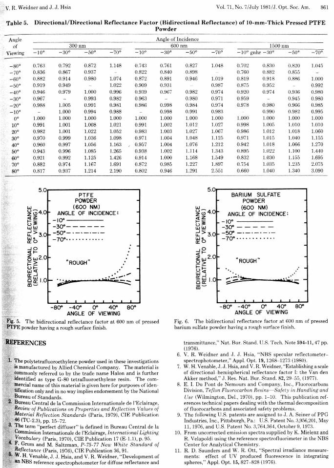
The bidi recti onal reflectan ce factor of pressed PTFEpowder listed in T able 5 shows how the reflectance varies overa wide range of viewing angles for four d ifferen t angles of incidence. These measurements were made by mean s of theNBS specular reflectorneter .f This ins trument is ordina rilyused for specular reflectance measuremen ts as a funct ion ofangle of incidence. It can be used to measure the bidirectionalreflectan ce of a diffuse sample in the plane of t he inciden tsample beam. Measur ements were mad e at 300, 600, and ,1500 nm for angles of incidence of - 10, - 30, - 50, and - 70°.The ang les of viewing were selected at 10° inte rva ls from - 80to + 80°. The bidir ectional reflectance data reported in T able5 are an average of the verti cal and horizon tal polar izat ions.The values for either polari zat ion varied from this average byas little as ± 0.2% to as mu ch as ± 20% depending on the combination of beam incidence and viewing angle. T hese da taare relative to the reflectan ce values obta ined at 0° (norma l)viewing. T he results list ed in T a ble 5 are represen tative ofthe bidirectional reflectance of a " rough" sur face prepa red bypressing the PTFE powder with a coarsely ground glass plate.Sa mples pr essed with a polish ed glass plate exhibit slightlyhigher valu es of reflectance, par ticularly at viewing anglesgreate r th an 75°. Figur e 5 illustr ates the bidi rectional reflectance proper t ies of pressed PTFE powder at 600 nm.Simi lar resul ts are shown for barium sulfate powder in Fig.6.
Further studies of the reflect ion propert ies of pressed PTFEpowder are being made at NB S. Among these propert ies arethe 45°10° or 0°/45° reflectan ce factors for the visible spect ralregion. The resu lts of these stud ies will be pu blished at afuture date.
250(NM)
350
450-:::::--750
60 20° 40° 60° 75°ANGLE OF INCIDENCE
1.015
1.010
1.005
1.000L..1lliiiI~~---L--L.....L."""'..J
oW WUoz l-~U Ww~...Jti~...Ja::: W
a:::
V. R. Weidner and J . J . Hsia Vol. 71, No. 7/J uly 1981/J . Opt. Soc. Am. 861
Table 5. Dir ectional/Direct ion al Refl ectance Factor (Bidir ect ional Reflectance ) of lO-mm -Thick Pressed PTFEPo wd er
Angle Angle of Incidenceof 300 nm 600 nm 1500 nm
Viewing - 100 - 300 - 500 - 700 -100 - 300 - 500 - 700 -100 gnhr - 300 -500 - 700
- 800 0.763 0.792 0.872 1.148 0.743 0.761 0.827 1.048 0.702 0.830 0.820 1.045- 700 0.836 0.867 0.937 0.822 0.840 0.898 0.760 0.882 0.855- 600 0.882 0:914 0.980 1.074 0.872 0.891 0.946 1.019 0.819 0.918 0.886 1.000- 500 0.919 0.949 1.022 0.909 0.931 0.987 0.875 0.952 0.992_ 400 0.946 0.979 1.000 0.996 0.939 0.967 0.982 0.974 0.920 0.974 0.936 0.980- 300 0.967 0.993 0.982 0.963 0.980 0.971 0.959 0.945 0.980- 200 0.988 1.005 0.991 0.981 0.986 0.998 0.984 0.974 0.978 0.980 0.966 0.985_ 100 1.000 0.994 0.988 0.998 0.991 0.983 0.990 0.982 0.995
00 1.000 1.000 1.000 1.000 1.000 1.000 1.000 1.000 1.000 1.000 1.000 1.000
100 0.991 1.001 1.008 1.021 0.991 1.002 1.012 1.027 0.998 1.005 1.010 1.010200 0.982 1.001 1.022 1.052 0.983 1.003 1.027 1.067 0.986 1.012 1.018 1.060
300 0.970 0.999 1.036 1.098 0.971 1.004 1.048 1.125 0.971 1.015 1.040 1.155
400 0.960 0.997 1.056 1.163 , 0.957 1.004 1.076 1.212 0.942 1.018 1.066 1.270
500 0.943 0.996 1.085 1.265 0.938 1.002 1.114 1.343 0.895 1.022 L.100 1.440600 0.921 0.992 1.125 1.426 0.914 1.000 1.168 1.549 0.832 1.030 1.155 1.695700 0.882 0.974 1.167 1.69] 0.872 0.985 1.227 1.897 0.754 1.035 1.235 2.075800 0.817 0.937 1.2] 4 2.190 0.802 0.946 1.291 2.55] 0.660 ].040 1.340 3.090
5.0r--- - - - - - - - - ---,
MROUGH "
- 800 - 40 0 00 400 800ANGLE OF VIEWING
BARIUM SULFATEPOWDER
(600 NM)ANGLE OF INCIDENCE:
- 100---- - -
- 300 - - - --- 500 _0 _ 0 - ' - ' -
- 7 00 •. • 0. • 0 •• '0 0
5.0- ----- - - - - -,
....>: .:>
· H' .....-_ ....---" ROUGH"
PTFEPOWDER
(60 0 NM)ANGLE OF INCIDENCE :
-100- - - - - -
-300- ------50°- ' -0_ ' -' -
-70°0• • . •• •• .• • 0
-800 -400 00 400 80 0
ANGLE OF VIEWING
w~~4.0
~~u~WW
~>3.0wo0::0
....J O<0 -~w2.0->1- -
~t:i0:: ....J
Q~ 1.01Il ~
..,...,......,..Fig. 5. The bidire ct ional reflectan ce factor at 600 nm of pressedPTFE powder having a rough sur face finish.
Fig. 6. T he bid irect ional reflectance factor at 600 nm of pressedbarium sulfate powder having a rough surface finish.
t ransmitta nce," Nat. Bur . Stand . U.S. Tech. Note 594-11, 47 pp.(1976).
6. V. R. Weid ner and ,J. J . Hsia, " NBS specular reflectometerspectrophoto mete r," App l. Opt. 19, 1268- 1273 (1980).
7. W. H. Venable, J . J . Hsia, and V. R. Weidner, "Establishing a scaleof dir ect ional- hem ispherical reflectance factor I: t he Van denAkker method," J . Res. Nat. Bur. Stand. 82, 29- 55, (1977).
8. E. I. Du Pont de Nemours and Company, Inc., Fluorocarbo nsDivision, T efl on Fluorocarbon Resins- Safety in Handling andUse (Wilmington, Del., 1970), pp . ] -1 0. T his pub lication references technical papers dealing with the thermal decompositionof fluoroca rbons and associated safety problems.
9. T he following U.S. patent s are assigned to J . A. Seiner of PPGIndustr ies, Inc., Pi ttsburgh, Pa.: U.S. Patent No. 3,956,20] , May11, 1976, and U.S. Pat ent No. 3,764,364, October 9, 1973.
10. From uncorrected emission spectra supplied by K. Mielenz andR. Velapoldi using the reference spectrofluorimete r in the NBSCente r for Analyt ical Chemist ry.
11. R. D. Sa unde rs and W. R. Ott, "Spect ra l irrad iance measur emen ts: effect of UV produced fluorescence in integrati ngspheres ," Appl. Opt . 15, 827- 828 (1976).
1. The polytetrafluoroeth ylene powder used in these invest igationsis manufactured by Allied Chemical Company. The material iscommonly refe rred to by the t rade name Halon and is fur t heridentifi ed as type G-80 tet rafluoroet hylene resin . The commercial name of this mater ial is given here for purposes of identification only and in no way implies endorsement by the NationalBureau of Standards.
2. Bureau Central de la Commission In tern ationale de l'Eclairage,Review of Pub lications on Propert ies and Reflect ion Values ofMaterial Ref lecti on S tandards (Pa ris , 1979), CIE P ublicat ion46 (TC-2.3), pp. 15- 72.
S. The term " perfect diffuser " is defined in Bur eau Centra l de laCommission Intern ationale de I'Eclairage, In ternational Lighting
4' Vocabulary (Paris, 1970), CIE Publication 17 (E-1.1), p. 95.. F. Grum an d M. Sa ltzman , P-75-77 N ew Wh ite Standard of
6 Reflectance (Paris, 1976), CIE Publicati on 36, 91.. W. H. Venabl e, J. J . Hsia, and V. R. Weidn er, " Development of
an NBS reference spectrophoto met er for diffuse reflectance and
REFERENCES