Greece III. Architecture A. Columns a. Columns are part of Post and Lintel type construction.

POST-LINTEL STRUCTURE

STRUCTURAL METHOD
POST-LINTEL STRUCTURE
POST-SLAB STRUCTURE
WALL SLAB STRUCTURE
STEEL STRUCTURE
COMPOSITE STRUCTURE

POST & LINTEL
Simple form of construction involving posts carrying horizontal beams or lintels, as in timber-framed work or in columnar and trabeated architecture.
Ancient Egyptian and Ancient Greek architecture was of this type, using stone.
Stonehenge is an example of post and lintel construction

Structural Shapes
Structural Shapes, Roofing, and Framing

POST & LINTEL SYSTEM
Post Lintel is a Frame structure Use of Concrete Materials, Mixing of aggregate,
gravel, sand, Cement with water. It may be lightweight or heavy weight structure. Mixing ratio: 1:2:4, 1:3:6 & 1:1.5:3 etc In more recent time it has been found possible to
produce steels. According to many codes & specifications such as 80ksi, 60ksi, & 40ksi etc.
60ksi steel is most commonly used.

FOUNDATION
The foundation is the part of a structure that is usually placed below the surface of the ground & that transmits the load
to the underlying soil or rock.

FOUNDATION TYPE
Footing
• Wall Footing
- R.C Wall
- Masonry Wall
• Column Footing
- Rectangular
- Square•Combined Footing
Pile
Mat, Raft or Deep Foundation
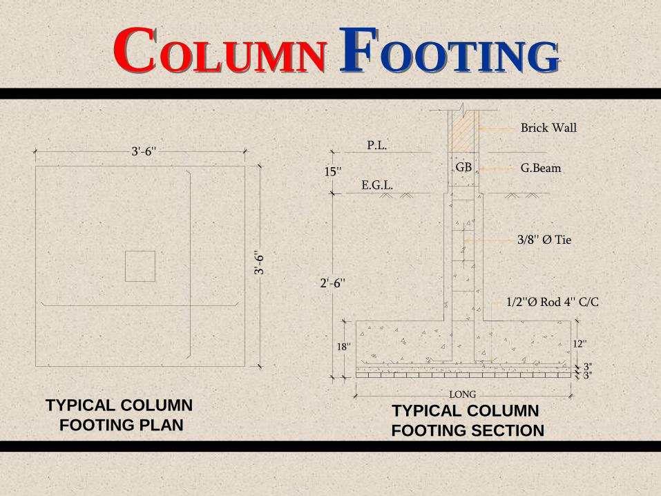
COLUMN FOOTING
1/2''Ø Rod 4'' C/C
3/8'' Ø Tie
G.Beam
Brick Wall
LONG
GB
3"3"
P.L.
E.G.L.
18''
2'-6''
15''
12''
3'-6
''
3'-6''
TYPICAL COLUMN
FOOTING PLANTYPICAL COLUMN
FOOTING SECTION

COLUMNA column is a vertical support structure.According to ACI Code : Rectangular column _
Minimum 96 in² or 8’’X12”, steel 4 bars, Tie 3/8’’ dia or ½’’ dia.Spiral column – Minimum 100 in² , 10’’ dia steel 6 bars, Tie 3/8’’ dia , Not exceed than 3’’ & less than 1’’
Circular Column
10''
10''10''
10''
8''
12''
Rectangular Column Square Column

ECONOMICAL COLUMN
SPAN
COLUMN SIZE
Column size not less than
10“x10” for ACI code
15'-0" to 21'-0"
depends on ground floor
perking & drive way
BEA
M C
OLU
MN
(PO
ST
-LIN
TEL)
ST
RU
CT
UR
E
COLUMN SPAN & SIZE

DOUBLE HEIGHT COLUMN THICKNESS
PO
ST
-LIN
TE
S
TR
UC
TU
RE
Double height column depends on slender test of column or effective length of column buckling For member with h/t up to 10 (approximately h/r up to 35) For column with h/t = 20 (approximately h/r up
to 70) R became 0.07
Team roll of dabble height column thickness, If column length is upward for axial load then column
section is enlarge for a column.

BEAM
The beam is a very sturdy structure. A beam is a horizontal pole. It is usually shaped as a rectangle so there is more balance between the poles. A beam is held up by one or two columns. If there are two columns, they are placed on either side of the beam. If there is one column, it is placed in the middle of the beam so each side is balanced. Beams are found in many places - in buildings, in homes, and in moving structures.

DISTRIBUTION LOADS
PO
ST
-LIN
TE
S
TR
UC
TU
RE
Distributed Load
DISSTRIBUTED LOAD
SECTION OF BEAM
Concentreted Load
SECTION OF BEAM
Concentrated Load

BEAM TYPES
According to Reinforcement there are two types of beam : Single reinforcement beam
Reinforcement bar are used in the tensile zone.
Double reinforcement beam Reinforcement bar are used in the tensile & Compression zone.
SINGLE REINFORCEMENT
BEAM SECTION
DOUBLE REINFORCEMENT
BEAM SECTION

BEAM TYPESAccording to Support there are four types of beam :
Simply Supported Beam
One end Continuous Supported Beam
BEA
M C
OLU
MN
(PO
ST
-LIN
TEL)
ST
RU
CT
UR
E

BEAM TYPES
Both end Continuous Supported Beam
Cantilever Beam
BEA
M C
OLU
MN
(PO
ST
-LIN
TEL)
ST
RU
CT
UR
E

Clear span of column & the beam thickness is convert to inches for column span length. For an example column span clear 20’-0” so for this region beam thickness 20” for this span
BEA
M C
OLU
MN
(PO
ST
-LIN
TEL)
ST
RU
CT
UR
E
20’
Column Span
12”
20”
BEAM THICKNESS

Structural Joint
Joint of Beam & Column
Beam
Column

ECONOMICAL CANTILEVER PORTION
PO
ST
-LIN
TE
S
TR
UC
TU
RE
we use to cantilever not less then 5’-0”
for open side on a support. But its
depends on overturning moment should
be balance by type of load or embedded
layer.

POST-LINTE STRUCTURE SLAB
PO
ST
-LIN
TE
S
TR
UC
TU
RE
SLABThere are two type of slab use in post lintel structural systemOne-way slabA one-way slab is essentially a rectangular beam of comparative large ratio of width depth. And steel use to short direction of slab.
One Way Reinforcement Slab
20'-0"
45'-0"
Bot
om w
ith
alt
.Ck
d.
10 m
m Ø
@ 6
" C
/C S
td.

POST-LINTE STRUCTURE SLAB
PO
ST
-LIN
TE
S
TR
UC
TU
RE
Two way slabMost rectangular reinforced concrete slab are supported on all four side by beam , girders or walls.
20'-0"
20'-0"
Botom with alt.Ckd.10 mm Ø @ 6" C/C Std.
Bot
om w
ith
alt
.Ckd
.10
mm
Ø @
6"
C/C
Std
.
12 mm Ø Extra top
Two Way Reinforcement Slab
POST-LINTE STRUCTURE SLAB
PO
ST
-LIN
TE
S
TR
UC
TU
RE
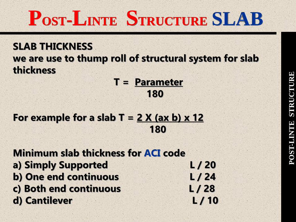
SLAB THICKNESSwe are use to thump roll of structural system for slab thickness
T = Parameter180
For example for a slab T = 2 X (ax b) x 12180
Minimum slab thickness for ACI codea) Simply Supported L / 20b) One end continuous L / 24c) Both end continuous L / 28d) Cantilever L / 10

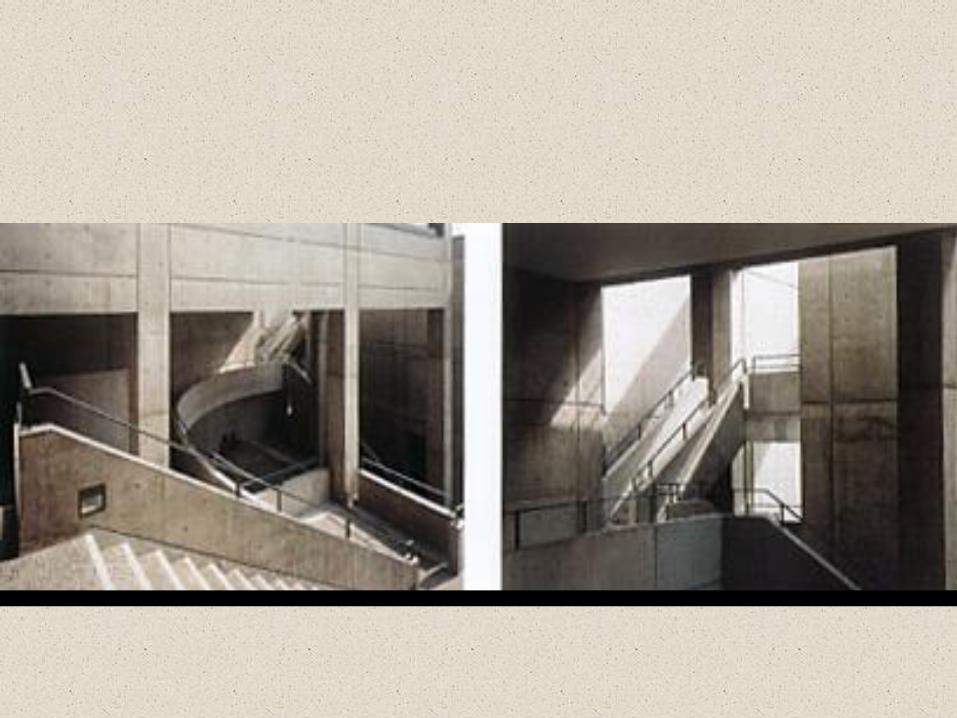
STAIRIN THE POST LINTEL STRUCTURE THERE USED THREE TYPES OF STAIR SECTION.
1. BEAM HANGING FROM LANDING LEVEL.2. BEAM INVERTED ON LANDING LEVEL.3. BEAM HANGING FROM SAME AS SLAB LEVEL.
PO
ST
-LIN
TE
S
TR
UC
TU
RE
3'-
9"
5"
3'-
9"
6"5"4'-2"10"10"10"10"10"10"10"10"10"2'-6"
AA
UP
STAIR PLAN

STAIR SECTIONS
PO
ST
-LIN
TE
S
TR
UC
TU
RE
10"
6"
10"
6"
SECTION : A-A
INVERTED BEAM IS USED IN LANDING LEVEL BEAM IS HANGING FROM THE LANDING LEVEL BEAM POSITION IS SAME TO SLAB LEVEL
SECTION : A-ASECTION : A-A
6"
10"
6"
10"10"
6"
10"
6"

1'-9
"1
'-0"
3"
7'-0
"
10'
-0"
3'-0
"
3'-0
"
3'-0
"4"
ROOF
4" L.C
NET
4"
Ø P
VC
SO
IL P
IPE
1"
Ø P
VC
VE
NT
PIP
E
DETAIL OF SANITARY PIPING
TYPICAL SECTION OF A/C HOLE
1'-8
" AC
10'-0
"
1'-8"
FLOOR
5'-4
"3
'-0"
FLOOR
DETAIL-G
1" THICK PLASTER
SANITARY & AC SECTION
PO
ST
-LIN
TE
S
TR
UC
TU
RE

Post lentil it self a farm structure
Out side exposed
structurally sound
structurally sustainable
usually it is economical
environmentally and earth quick save.
Beam-Column Image of Architecture
BEA
M C
OLU
MN
(PO
ST
-LIN
TEL)
ST
RU
CT
UR
E

Expression
Post & lintels are shown as frame structures. But columns & louvers.
Solid & void relationship is less. The invert beam can be seen from above. Presence of continuous beam Columns are placed along the age of the
building.
BEA
M C
OLU
MN
(PO
ST
-LIN
TEL)
ST
RU
CT
UR
E

POST-LINTE ADVANTAGES
PO
ST
-LIN
TE
S
TR
UC
TU
RE
AESTHETICSAesthetically this structural system seems quite sound by using the expression of post-lintel structure in the exterior facades.
Sometimes the heavy or rigid masses are treated politely by using the framework of the post-lintel which gives an extra ordinary looks.
SPAN & SPACELarger span (column to column distance) of building is possible to design in this system.
For the large span the lintel height become larger for this a large space seems small, as the lacking of clear height.
Sometimes this problem creates visual disturbance, which is avoided, in flat slab.

POST-LINTE ADVANTAGES
PO
ST
-LIN
TE
S
TR
UC
TU
RE
ECONOMICThe construction cost of this system is slightly high for the time consuming casting of beam and slab and the use of R.C.C.
The maintenance cost of this system remains lower than the other structural system for its long lasting characteristics.
CLIMATEConsidering the climate this system is more suitable for our country.
The admission of heat become reduced in this system, as the heat transferred from the slab to beam and then from the beam to floor.
The control of openings admits the little amount of heat in the building.For the free flowing plan light and ventilation can easily insert the building.

POST-LINTE ADVANTAGES
PO
ST
-LIN
TE
S
TR
UC
TU
RE
ENVIRONMENT
This structural system having less self-loads which reduces the risk of danger of earth quack. It can resist the buckling or bending effect of the building from the strong wind flow. It has the capability of fire resistance for the construction material (R.C.C.).So this system is very much suiting with respect to our environment.
CONSTRUCTION TECHNICS
In this structural system construction process takes a long time for the casting of beam and slab because at first column and beam cast and after that the slab cast. High cost materials are used in this system. In post-lintel system ducting process is not so easier compared to Post-slab.

POST-LINTE ADVANTAGES
PO
ST
-LIN
TE
S
TR
UC
TU
RE
OPENNINGSIn post-lintel system 50% area of the external facade is remaining for the openings of the building. For this there is a control over use of openings. The admass of light and ventilation is smaller compared to post-slab.
SUSTAINABILITYSustainability means the ultimate capacity of individual members and as well as the whole structure against any types of overloading such as cyclones, earth quacks, etc. Sustainability of structures may also termed as factor of safety because overloading is allowed only up to the safety level which was taken in considering at the time of design. Stability of any structure is the critical point of failure. If stability is not satisfied it limits the values, then the failure may come suddenly. This system has less possibility of failure than the other structural system.

POST-LINTE ADVANTAGES
PO
ST
-LIN
TE
S
TR
UC
TU
RE
FLOOR SLABFloor slab is a slab supported on ground generally distribute load to the ground uniformly. It also increases the bearing capacity of soil as the load distributes combined.
SOLID-VOID RATIOBy using the framework of post-lintel system we can make a sense full solid-void ratio which illuminate the monotonous effect.
CANTILEVER OR OVERHANGThe portion of any structure that is over hanged without any support termed as cantilever. Sometimes cantilever construction is economical and looks aesthetically attractive which may become a useful part of that structure.
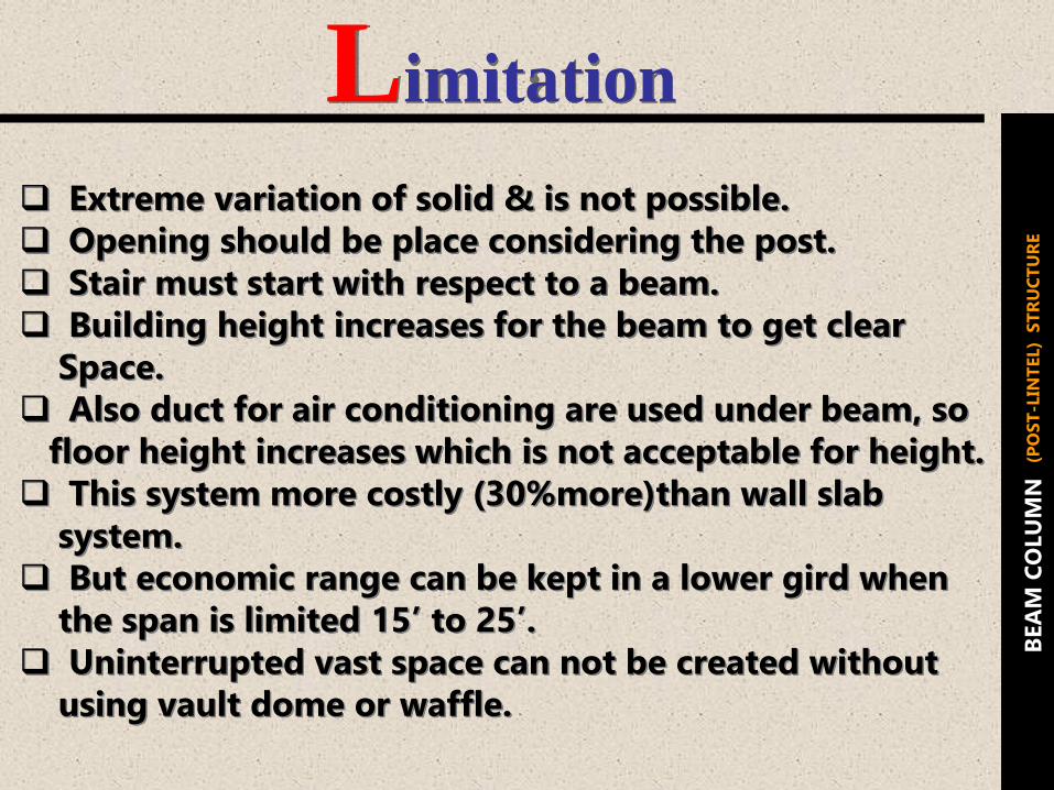
Limitation
Extreme variation of solid & is not possible. Opening should be place considering the post. Stair must start with respect to a beam. Building height increases for the beam to get clear
Space. Also duct for air conditioning are used under beam, so
floor height increases which is not acceptable for height. This system more costly (30%more)than wall slab
system. But economic range can be kept in a lower gird when
the span is limited 15’ to 25’. Uninterrupted vast space can not be created without
using vault dome or waffle.
BEA
M C
OLU
MN
(PO
ST
-LIN
TEL)
ST
RU
CT
UR
E

POST-LINTEL STRUCTURE

Rokko HousingArchitect Tadao Ando
Example

ROKOKO HOUSING
ARCHITECT
ANDO

THE WESTIN DHAKA
HIRSCH BEDNER ASSOCIATES
Example

MIRPUR C.R.P HOSPITALSECTION-14, MIRPUR, DHAKAARCHITECTMD.RAFIQ AZAM
Example

LAYOUT PLAN

BASEMENT PLAN

GROUND FLOOR PLAN

3RD FLOOR PLAN
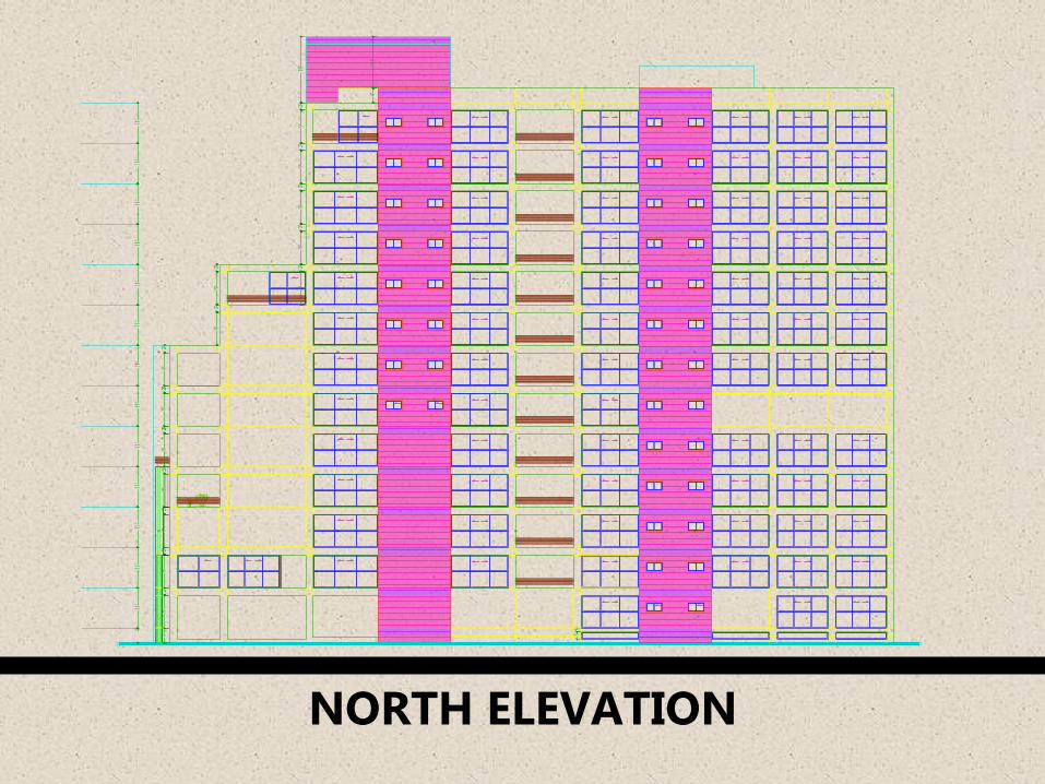
NORTH ELEVATION

SOUTH ELEVATION

EAST ELEVATION

WEST ELEVATION

SECTION

SECTION

VIEW OF C.R.P

VIEW OF FRAM

VIEW OF FRAM STRUCTURE

Example
EQUITY INSIGNIAROAD NO : 01, KHULSHI , CHITTAGONG.ARCHITECTMAMNOON M. CHOWDHURY.MAHMUDUL ANWAR RIYAAD.

LAYOUT PLAN
7
6
5
4
3
2
1
A B C D E F G H
HGFEDCBA
1
2
3
4
5
6
7
A1
A1
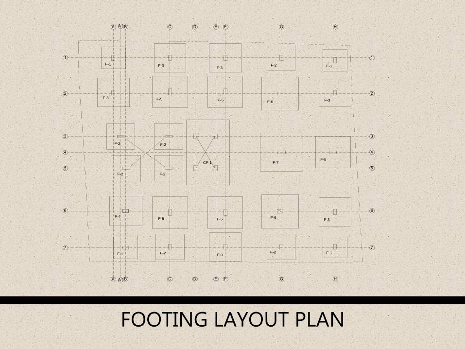
FOOTING LAYOUT PLAN
CF-1
A1
A1
F-1
F-1 F-1
F-1
F-2 F-2
F-2 F-2
F-2 F-2
F-2F-3F-3
F-3F-3
F-3
F-3
F-4F-5 F-5
F-5 F-5
F-5
F-6
F-7
F-6
1
2
3
4
5
6
7 7
6
5
4
3
2
1
A B C D E F G H
HGFEDCBA

GROUND FLOOR PLAN
5'-7"
FIXED GRILL (FLOOR TO 7'-0")
GRILL DOOR
FIXED GRILL (FLOOR TO 7'-0")
FIXED GLASS
ELECT. RISERS
ELECT. RISERS
1
2
3
SUBSTATION &
GENERATOR ROOM
UP
+2'-0"
+2'-0"
+2'-0"
+2'-0"
+2'-0"
+2'-0"
SEPTIC TANKLOCATION OF
OU
T D
OO
R M
ETA
L H
AL
LID
E
PR
OP
OS
ED
U
GR
LO
CA
TIO
N
TA
P F
OR
C
AR
WA
SH
5"X
4'-2
" H
IGH
BR
ICK
WA
LL
PR
OP
OS
ED
LO
CA
TIO
NO
F D
EE
P T
UB
EW
ELL
GAS RISER
NA
ME
PL
ATE
DRIVERS' COMMON
ROOM
CARETAKER'S
CARETAKER'S
GA
S R
ISE
R
D R I V E W A Y
+1'-6"
EN
TR
Y
A
D R I V E W A Y
+0'-0"
C-01
A
C-02C-03 C-04 C-05 C-06
C-15 C-14 C-13 C-12 C-11
C-07
C-08
C-09
C-10
METER ROOM
M.S
. SL
IDIN
G G
ATE
(SE
E D
ETA
IL)
GUARD
ROOM
GREEN
GARDEN
D R
I V
E
W
A
Y
+2'-6"

TYPICAL FLOOR PLAN
2
3
1
A A

2ND FLOOR(+24'-6")
1ST FLOOR(+14'-6")
3RD FLOOR(+34'-6")
4TH FLOOR(+44'-6")
5TH FLOOR(+54'-6")
6TH FLOOR(+64'-6")
7TH FLOOR(+74'-6")
8TH FLOOR(+84'-6")
ROOF(+94'-6")
SLAB THICKNESS FOR CANTILEVER PART WILL
NOT EXCEED 5"
PARKING LEVEL(+1'-6")
ROAD LEVEL(±0'-0")
BRICK CLADDED SURFACE
PLASTERED SURFACE PAINT
FRONT ELEVATION

SLAB THICKNESS FOR CANTILEVER PART WILL NOT EXCEED 5"SEE 3D & SECTION
SLAB THICKNESS FOR CANTILEVER PART WILL NOT EXCEED 5"LINTEL SLAB OF 8TH FLOOR
13'-0"
10'-0"
10'-0"
7'-1"
AC
AC
AC
AC
AC
AC
AC
AC
AC
AC
AC
AC
AC
AC
AC
2ND FLOOR(+24'-6")
1ST FLOOR(+14'-6")
3RD FLOOR(+34'-6")
4TH FLOOR(+44'-6")
5TH FLOOR(+54'-6")
6TH FLOOR(+64'-6")
7TH FLOOR(+74'-6")
8TH FLOOR(+84'-6")
ROOF(+94'-6")
PARKING LEVEL(+1'-6")
ROAD LEVEL(±0'-0")
NORTHT ELEVATION

SECTION
6'-7"
7'-0"
7'-5"
8'-8"
8'-3"
5"
3"
LEVEL +15'-0"8'-8"
7'-0" 10"
6"
10
'-0"
3'-
6"
CONFIRM HEIGHT FROM LIFT SUPPLIER
3'-
0"
8'-
0"
13
'-0"
5'-
0"
6"
OVER HEAD WATER RESERVOIR
10
'-0"
3'-
0"
3RD FLOOR(+35'-0")
4TH FLOOR(+45'-0")
5TH FLOOR(+55'-0")
6TH FLOOR(+65'-0")
7TH FLOOR(+75'-0")
8TH FLOOR(+85'-0")
ROOF(+95'-0")
8'-
0"
5'-
0"
10
'-0"
10
'-0"
10
'-0"
10
'-0"
10
'-0"
10
'-0"
10
'-0"
10
'-0"
10
'-0"
10
'-0"
10
'-0"
10
'-0"
10
'-0"
7'-
0"
3'-
0"
3'-
0"
7'-
0" 1
0'-
0"
3'-
0"
7'-
0" 1
0'-
0"
10
'-0"
7'-
0"
3'-
0"
10
'-0"
7'-
0"
3'-
0"
10
'-0"
7'-
0"
3'-
0"
10
'-0"
7'-
0"
3'-
0"
10
'-0"
11
'-0"
6'-
6"
LIFT CORE
LEVEL +1'-6"
LEVEL +2'-6"
UNDER GROUND WATER RESERVOIR
10
'-0"
12
'-6"
3'-
0"
7'-
0" 1
0'-
0"
13
'-6"
PARKING LEVEL(+1'-6")
ROAD LEVEL(±0'-0")
2ND FLOOR(+25'-0")
1ST FLOOR(+15'-0")

0"1'-3"
3'-6"
2ND FLOOR(+25'-0")
1ST FLOOR(+15'-0")
3RD FLOOR(+35'-0")
4TH FLOOR(+45'-0")
5TH FLOOR(+55'-0")
6TH FLOOR(+65'-0")
7TH FLOOR(+75'-0")
8TH FLOOR(+85'-0")
ROOF(+95'-0")
3" BRICK CLADDING
SLAB THICKNESS FOR CANTILEVER PART WILL
NOT EXCEED 5"
3" SKIRTING
PARKING LEVEL(+1'-6")
ROAD LEVEL(±0'-0")
3'-7"
4'-0"
10
'-6"
6"3"
9'-3"
9'-3"
3"
6"
9'-3"
3"
6"
9'-3"
3"
6"
9'-3"
3"
6"
3"
3"
7'-0"
4'-0"
6"
5"
6"
3'-0"
3"
6'-9"
3'-0"
3"
6'-9"
3'-0"
3"
6'-9"
3'-0"
3" SKIRTING
ROAD LEVEL(±0'-0")
PARKING LEVEL(+1'-6")
ROOF(+94'-6")
8TH FLOOR(+84'-6")
7TH FLOOR(+74'-6")
6TH FLOOR(+64'-6")
5TH FLOOR(+54'-6")
4TH FLOOR(+44'-6")
3RD FLOOR(+34'-6")
1ST FLOOR(+14'-6")
2ND FLOOR(+24'-6")
13
'-6"
10
'-0"
10
'-0"
10
'-0"
10
'-0"
10
'-0"
10
'-0"
10
'-0"
10
'-0"
10
'-0"
2'-6"
7'-6"
3'-6"
3"
6'-9"
3'-0"
3"
6'-9"
3'-0"
3"
6'-9"
3'-0"
3"
6'-9"
3'-0"
3"
6'-9"
6'-9"
3'-0"
6"3"
9'-3"
6"3"
9'-3"
6"3"
9'-3"
6"
3" BRICK CLADDING
1'-6"
1'-6"
6"
2'-0"
6"
7'-0"
6"
6" 3'-6"
10
'-0"
3'-6"
7'-0"
3'-0"
3'-0"
7'-0"
3'-0"
7'-0"
3'-0"
7'-0"
3'-0"
7'-0"
3'-0"
7'-0"
3'-0"
7'-0"
3'-0"
7'-0"
3'-9"
6'-3"
10
'-0"
10
'-0"
10
'-0"
10
'-0"
10
'-0"
10
'-0"
10
'-0"
10
'-0"
10
'-0"
13
'-6"
1'-8"
SCALE : not to scale
SECTION : 1-1
ROOF(+95'-0")
8TH FLOOR(+85'-0")
7TH FLOOR(+75'-0")
6TH FLOOR(+65'-0")
5TH FLOOR(+55'-0")
4TH FLOOR(+45'-0")
3RD FLOOR(+35'-0")
1ST FLOOR(+15'-0")
2ND FLOOR(+25'-0")
SECTION:2-2
SCALE : not to scale
PARKING LEVEL(+1'-6")
ROAD LEVEL(±0'-0")
3" SKIRTING
SLAB THICKNESS FOR CANTILEVER PART WILL NOT EXCEED 5"
ROAD LEVEL(±0'-0")
PARKING LEVEL(+1'-6")
3" BRICK CLADDING
3'-0"
7'-0"
3'-0"
7'-0"
3'-0"
3'-9"
6'-3"
6'-9"
5"
12
'-1"
13
'-6"
10
'-0"
10
'-0"
10
'-0"
10
'-0"
10
'-0"
10
'-0"
10
'-0"
10
'-0"
10
'-0"
2'-6"
7'-6"
7'-0"
3'-0"
7'-0"
3'-0"
7'-0"
3'-0"
7'-0"
3'-0"
7'-0"
3'-0"
7'-0"
SCALE : not to scale
SECTION:3-3
4'-0"
10
'-6"
6"
6'-9"
6"
2'-0"
6"3
"6
'-9"
6"
2'-0"
6"3
"6
'-9"
6"
2'-0"
6"3
"3"
6"
2'-0"
6"
6'-9"
3"
6"
2'-0"
6"
6'-9"
3"
6"
9'-3"
PART SECTION

Niaz ahmad zawad-ug-09-06-05-007Md. Jahangiralam-ug-09-06-05-014Shirin akhter-ug-09-06-05-018
THANK YOU EVERYBODY.