POSICON positioning control, BU 0510 - NORD · POSICON positioning control – Supplementary manual...
104
EN BU 0510 POSICON positioning control Supplementary manual for series SK 500E
Transcript of POSICON positioning control, BU 0510 - NORD · POSICON positioning control – Supplementary manual...

EN BU 0510
POSICON positioning control Supplementary manual for series SK 500E

POSICON positioning control – Supplementary manual for series SK 500E
2 BU 0510 EN-4816

Table of Contents
BU 0510 EN-4816 3

POSICON positioning control – Supplementary manual for series SK 500E
4 BU 0510 EN-4816
Pos: 3 /Allgemei n/Steuer module/Inhaltsverzeichnis @ 0\mod_1317978518480_388.docx @ 4078 @ @ 1
Table of Contents === Ende der Liste für Textmar ke Inhaltsverzeichnis ===
1 Introduction ................................................................................................................................................. 8 1.1 General .............................................................................................................................................. 8
1.1.1 Documentation ..................................................................................................................... 8 1.1.2 Document History ................................................................................................................. 8 1.1.3 Copyright notice .................................................................................................................... 8 1.1.4 Publisher .............................................................................................................................. 9 1.1.5 About this manual ................................................................................................................. 9
1.2 Other applicable documents .............................................................................................................. 9 1.3 Presentation conventions ................................................................................................................. 10
1.3.1 Warning information ........................................................................................................... 10 1.3.2 Other information ................................................................................................................ 10
2 Safety ......................................................................................................................................................... 11 2.1 Intended use .................................................................................................................................... 11 2.2 Selection and qualification of personnel ........................................................................................... 11
2.2.1 Qualified personnel ............................................................................................................. 11 2.2.2 Qualified electrician ............................................................................................................ 11
2.3 Safety information ............................................................................................................................ 12 3 Electrical Connection ................................................................................................................................ 13
3.1 Connection to device........................................................................................................................ 13 3.1.1 Control terminal details ....................................................................................................... 15
3.2 Encoders .......................................................................................................................................... 24 3.2.1 CANopen absolute encoders .............................................................................................. 24 3.2.1.1 Approved CANopen absolute encoders (with bus cover) 24 3.2.1.2 Contact Assignment for CANopen encoders 24 3.2.1.3 RJ45 WAGO- Connection module 25 3.2.2 Colour and contact assignments for encoders.................................................................... 26 3.2.2.1 Incremental encoder 27 3.2.2.2 Encoders for SK 540E and SK 545E 28
4 Function description ................................................................................................................................. 33 4.1 Introduction ...................................................................................................................................... 33 4.2 Position Detection ............................................................................................................................ 33
4.2.1 Position detection with incremental encoders ..................................................................... 33 4.2.1.1 Approach reference point 34 4.2.1.2 Residual position 35 4.2.2 Position detection with absolute encoders .......................................................................... 36 4.2.2.1 Supplementary settings – CANopen absolute encoders 36 4.2.2.2 Supplementary settings - SSI absolute encoders 37 4.2.2.3 Referencing an absolute encoder 38 4.2.2.4 Manual commissioning of the CANopen absolute encoder 38 4.2.3 Encoder monitoring ............................................................................................................ 39 4.2.4 Linear or optimised path positioning method ...................................................................... 40 4.2.4.1 Optimised path positioning 41
4.3 Setpoint specification ....................................................................................................................... 44 4.3.1 Absolute set position (position array) via digital inputs / BUS IO Bits ................................. 44 4.3.2 Relative set position (position increment array) via digital inputs / BUS IO Bits ................. 45 4.3.3 Bus setpoints ...................................................................................................................... 46 4.3.3.1 Absolute set position (position array) via field bus 46 4.3.3.2 Relative set position (position increment array) via field bus 46
4.4 "Teach - In“ – Function for saving positions ..................................................................................... 47 4.5 Speed ratio of setpoint and actual values ........................................................................................ 48 4.6 Position control ................................................................................................................................ 49
4.6.1 Position control - Position control variants (P600) .............................................................. 49 4.7 Position control – Method of operation ............................................................................................. 51 4.8 Remaining path positioning .............................................................................................................. 52 4.9 Synchronous control ........................................................................................................................ 53
4.9.1 Communication settings ..................................................................................................... 54 4.9.2 Ramp time and maximum frequency settings on the slave ................................................ 56 4.9.3 Setting the speed and position controls .............................................................................. 56

Table of Contents
BU 0510 EN-4816 5
4.9.4 Taking a speed ratio between master and slave into account ............................................ 57 4.9.5 Monitoring functions ........................................................................................................... 58 4.9.5.1 Achievable precision of position monitoring 58 4.9.5.2 Master switch-off on slave error or position slip error 58 4.9.5.3 Slip error monitoring on the slave 59 4.9.6 Slave reference point run - Axis in a synchronous application ........................................... 60 4.9.7 Offset switching in synchronous operation ......................................................................... 60 4.9.8 Flying Saw (extended synchronous operation function) ..................................................... 61 4.9.8.1 Determination of acceleration path and initiator position 63 4.9.8.2 Diagonal saw 64
4.10 Output messages ............................................................................................................................. 65 5 Commissioning ......................................................................................................................................... 66 6 Parameters ................................................................................................................................................. 68
6.1 Description of parameters ................................................................................................................ 68 6.1.1 Operating displays .............................................................................................................. 69 6.1.2 Speed control ..................................................................................................................... 69 6.1.3 Control terminals ................................................................................................................ 70 6.1.4 Additional parameters ......................................................................................................... 78 6.1.5 Positioning .......................................................................................................................... 82
7 Operating status messages ..................................................................................................................... 91 7.1 Messages ......................................................................................................................................... 91 7.2 FAQ operational problems ............................................................................................................... 95
7.2.1 Operation with speed feedback, without position control .................................................... 95 7.2.2 Operation with active position control ................................................................................. 95 7.2.3 Position control with incremental encoders ........................................................................ 96 7.2.4 Position control with absolute encoders ............................................................................. 96 7.2.5 Miscellaneous encoder faults (universal encoder interface) ............................................... 97
8 Technical Data ........................................................................................................................................... 98 9 Appendix .................................................................................................................................................... 99
9.1 Service and commissioning information ........................................................................................... 99 9.2 Documents and software ................................................................................................................. 99 9.3 Keyword Index ............................................................................................................................... 100 9.4 Abbreviations ................................................................................................................................. 101

POSICON positioning control – Supplementary manual for series SK 500E
6 BU 0510 EN-4816
Pos: 5 /Allgemei n/Steuer module/Abbil dungsverzeichnis @ 0\mod_1317978515699_388.docx @ 3917 @ @ 1
List of illustrations === Ende der Liste für Textmar ke Abbildungsverzeichnis ===
Figure 1: Rotary platform positioning with a single-turn application ....................................................................... 42 Figure 2: Rotary platform positioning with a multiturn application .......................................................................... 43 Figure 3: Position control sequence ...................................................................................................................... 51 Figure 4: Example of the flaying saw principle....................................................................................................... 62 Figure 5: Flying saw - Diagonal saw ...................................................................................................................... 64 Figure 6: Explanation of parameter description ..................................................................................................... 68

List of tables
BU 0510 EN-4816 7
Pos: 7 /Allgemei n/Steuer module/Tabell enverzeichnis @ 0\mod_1317978519199_388.docx @ 4124 @ @ 1
List of tables === Ende der Liste für Textmar ke Tabellenverzeichnis ===
Table 1: CANopen encoders approved by NORD ................................................................................................. 24 Table 2: RJ45 WAGO connection module ............................................................................................................. 25 Table 3: Colour and contact assignments for NORD – TTL / HTL incremental encoders ...................................... 27 Table 4: Colour and contact assignment for SIN/COS encoders ........................................................................... 28 Table 5: Signal details for SIN/COS encoders ....................................................................................................... 28 Table 6: Signal details for Hiperface encoders ...................................................................................................... 29 Table 7: Colour and contact assignment for Hiperface encoders .......................................................................... 29 Table 8: Colour and contact assignment for EnDat encoders ............................................................................... 30 Table 9: Colour and contact assignment for SSI encoders .................................................................................... 31 Table 10: Colour and contact assignment for BISS encoders ............................................................................... 32 Table 11: CANopen encoder cycle time dependent on the baud rate ................................................................... 37 Table 12: Parameter P604 encoder type selection ................................................................................................ 40 Table 13: assignment of addresses ....................................................................................................................... 59 Table 14: Digital output messages for positioning function .................................................................................... 65 Pos: 10 /Anl eitungen/Elektroni k/Bussysteme/1. Einführung/!Kapitel Ei nlei tung @ 8\mod_1441625462919_388.docx @ 2235978 @ 1 @ 1

POSICON positioning control – Supplementary manual for series SK 500E
8 BU 0510 EN-4816
1 Introduction Pos: 11 /Anl eitungen/Elektroni k/Bussysteme/1. Einführung/!Abschnitt Allgemeines @ 8\mod_1441352725095_388.docx @ 2235719 @ 2 @ 1
1.1 General Pos: 12 /Anl eitungen/Elektroni k/POSIC ON/1. Einl eitung/D okumentation [POSICON ] @ 14\mod_1479987697147_388.docx @ 2308098 @ 3 @ 1
1.1.1 Documentation
Name: BU 0510
Part number: 6075102
Series: POSICON for
NORDAC PRO and (SK 530E ... SK 535E)
NORDAC PROseries frequency inverters
(SK 540E ... SK 545E)
Pos: 14 /Anl eitungen/Elektroni k/POSIC ON/1. Einl eitung/D okumenthistorie [POSIC ON: SK 5xxE] @ 14\mod_1479987696548_388.docx @ 2308062 @ 3 @ 1
1.1.2 Document History
Issue Series Version Remarks
Order number Software
BU 0510, June 2007
SK 530E … SK 535E V 1.6 R0 First issue
6075102/ 2307 BU 0510, September 2011
SK 530E … SK 535E V 2.0 R0 • Implementation of the SK 54xE series with universal encoder interface for SIN/COS, Hiperface, EnDat 2.1, SSI and BISS encoders,
• "Flying Saw" technology function, • Extension of static positions from 15 to 63 (for
SK 54xE 4x63 positions, depending on the parameter set)
• Various corrections
6075102/ 3911 SK 540E … SK 545E V 2.0 R0
BU 0510, November 2016
SK 530E … SK 535E V 3.1 R1 • "Remaining path positioning technology function
• HTL encoders can now be used for positioning Supplementation of the corresponding parameters (P618, P619, P620)
• Extensive revision
6075102/ 4816 SK 540E … SK 545E V 2.3 R2
Pos: 15 /Anl eitungen/Elektroni k/Bussysteme/1. Einführung/Urheberrechtsver mer k @ 13\mod_1476364057823_388.docx @ 2265425 @ 3 @ 1
1.1.3 Copyright notice As an integral component of the device or the function described here, this document must be provided to all users in a suitable form.
Any editing or amendment or other utilisation of the document is prohibited. Pos: 16 /Allgemein/Allgemeing ültige M odul e/---------Seitenumbruch kompakt --------- @ 13\mod_1476369695906_0.docx @ 2265495 @ @ 1

1 Introduction
BU 0510 EN-4816 9
Pos: 17 /Anl eitungen/Elektroni k/Bussysteme/1. Einführung/Her ausgeber @ 8\mod_1441371998467_388.docx @ 2235820 @ 3 @ 1
1.1.4 Publisher
Getriebebau NORD GmbH & Co. KG Getriebebau-Nord-Straße 1
22941 Bargteheide, Germany
http://www.nord.com/
Tel.: +49 (0) 45 32 / 289-0
Fax: +49 (0) 45 32 / 289-2253 Pos: 18 /Anl eitungen/Elektroni k/POSIC ON/1. Einl eitung/Zu diesem H andbuch [POSICON ] @ 14\mod_1479993048787_388.docx @ 2308170 @ 3 @ 1
1.1.5 About this manual This manual is intended to assist you in the setup of a positioning application for a frequency inverter manufactured by Getriebebau NORD GmbH & Co. KG (abbreviated as NORD). It is intended for all qualified electricians who plan, install and set up the positioning application ( Section 2.2 "Selection and qualification of personnel"). The information in this manual assumes that the qualified electricians who are entrusted with this work are familiar with using electronic drive technology.and in particular with devices manufactured by NORD.
This manual only contains information and descriptions of the POSICON technology function and the relevant additional information for frequency inverters manufactured by Getriebebau NORD GmbH & Co. KG. Pos: 20 /Anl eitungen/Elektroni k/POSIC ON/1. Einl eitung/Mitgel tende D okumente [POSICON, PLC] @ 14\mod_1479993719061_388.docx @ 2308206 @ 2 @ 1
1.2 Other applicable documents This document is only valid in combination with the operating instructions for the frequency inverter which is used. Safe commissioning of the drive application depends on the availability of the information contained in this document.. A list of the documents can be found in Section 9.2 "Documents and software".
The necessary documents can be found under www.nord.com. Pos: 21 /Allgemein/Allgemeing ültige M odul e/---------Seitenumbruch kompakt --------- @ 13\mod_1476369695906_0.docx @ 2265495 @ @ 1

POSICON positioning control – Supplementary manual for series SK 500E
10 BU 0510 EN-4816
Pos: 22 /Anl eitungen/Elektroni k/Bussysteme/1. Einführung/!Abschnitt Dars tell ungskonventi onen @ 8\mod_1441373607811_388.docx @ 2235851 @ 2 @ 1
1.3 Presentation conventions Pos: 23 /Anl eitungen/Elektroni k/Bussysteme/1. Einführung/War nhi nweise @ 8\mod_1441373791790_388.docx @ 2235882 @ 33 @ 1
1.3.1 Warning information Warning information for the safety of the user and the bus interfaces are indicated as follows:
DANGER
This warning information warns against personal risks, which may cause severe injury or death.
WARNING
This warning information warns against personal risks, which may cause severe injury or death.
CAUTION
This warning information warns against personal risks, which may cause slight or moderate injuries.
NOTICE
This warning warns against damage to material.
1.3.2 Other information
Information This information shows hints and important information.
Pos: 25 /Anl eitungen/Elektroni k/Bussysteme/2. Sicherheit/!Kapitel Sicher hei t @ 8\mod_1441952463663_388.docx @ 2236460 @ 1 @ 1

2 Safety
BU 0510 EN-4816 11
2 Safety Pos: 27 /Anl eitungen/Elektroni k/POSIC ON/2. Sicherheit /Besti mmungsgemäße Ver wendung [POSIC ON] @ 14\mod_1479994530918_388.docx @ 2308242 @ 2 @ 1
2.1 Intended use The POSICON technology function from Getriebebau NORD GmbH & Co. KG is a software-assisted functional extension for frequency inverters manufactured by NORD. It forms an integral part of the frequency inverter and cannot be used without this. Because of this, all of the specific safety information for the relevant frequency inverter contained in the relevant manual ( Section 9.2 "Documents and software") apply without restriction.
The POSICON technology function is essentially used as a solution for complex drive applications with positioning functions which are implemented using frequency inverters manufactured by NORD. Pos: 28 /Anl eitungen/Elektroni k/POSIC ON/2. Sicherheit /Auswahl und Qualifi kati on des Personals [POSIC ON] @ 14\mod_1479994531376_388.docx @ 2308278 @ 233 @ 1
2.2 Selection and qualification of personnel The POSICON technology function may only be commissioned by qualified electricians. These must have the necessary knowledge of the technology functions and the electronic drive technology and the configuration aids which (e.g. NORD CON software) which are used, as well as the peripherals (including the controller) which are used in association with the drive application.
In addition, the qualified electricians must also be familiar with the installation, commissioning and operation of the sensors and electronic drive technology, as well as all of the accident prevention regulations, guidelines and laws which apply at the place of use.
2.2.1 Qualified personnel Qualified personnel includes persons who due to their specialist training and experience have sufficient knowledge in a specialised area and are familiar with the relevant occupational safety and accident prevention regulations as well as the generally recognised technical rules.
These persons must be authorised to carry out the necessary work by the operator of the system.
2.2.2 Qualified electrician An electrician is a person who, because of their technical training and experience, has sufficient knowledge with regard to
• Switching on, switching off, isolating, earthing and marking power circuits and devices, • Proper maintenance and use of protective devices in accordance with defined safety standards. • Emergency treatment of injured persons. Pos: 29 /Allgemein/Allgemeing ültige M odul e/---------Seitenumbruch kompakt --------- @ 13\mod_1476369695906_0.docx @ 2265495 @ @ 1

POSICON positioning control – Supplementary manual for series SK 500E
12 BU 0510 EN-4816
Pos: 31 /Anl eitungen/Elektroni k/POSIC ON/2. Sicherheit /Sicher hei tshi nweise [POSICON , PLC] @ 14\mod_1479994531814_388.docx @ 2308316 @ 2 @ 1
2.3 Safety information Only use the technology function POSICON positioning control and the frequency inverter from Getriebebau NORD GmbH & Co. KG for their intended purposes as stated in Section 2.1 "Intended use".
Observe the instructions in this manual in order to ensure the safe use of the technology function.
Only commission the frequency inverter in a technically unmodified form and not without the necessary covers. Take care that all connections and cables are in good condition.
Work on and with the frequency inverter must only be carried out by qualified personnel, Section 2.2 "Selection and qualification of personnel". Pos: 33 /Anl eitungen/Elektroni k/POSIC ON/3. Elektrischer Anschl uss/!El ektrischer Anschluss_Ü berschrift @ 14\mod_1480330614897_388.docx @ 2308449 @ 1 @ 1

3 Electrical Connection
BU 0510 EN-4816 13
3 Electrical Connection Pos: 34 /Anl eitungen/Elektroni k/FU und Starter/1. Allgemei nes/Sicherheits- und Installati onshi nweise/Sicher heitshi nweise/verschiedene/WARNUNG - El ektrischer Schlag ( nicht unter Spannung ar beiten) @ 14\mod_1480331381423_388.docx @ 2308485 @ @ 1
WARNING Electric shock
Touching electrically conducting components may cause an electric shock and severe or possibly fatal injury. • Disconnect the frequency inverter from the power supply before starting installation work. • Only work on devices which have been disconnected from the power supply. Pos: 35 /Anl eitungen/Elektroni k/FU und Starter/1. Allgemei nes/Sicherheits- und Installati onshi nweise/Sicher heitshi nweise/verschiedene/WARNUNG - El ektrischer Schlag ( Wartezeit) @ 14\mod_1480332099956_388.docx @ 2308520 @ @ 1
WARNING Electric shock
The frequency inverter carries hazardous voltage for up to 5 minutes after being switched off. • Only start work after a waiting period of at least 5 minutes after switching off the mains supply
(disconnection). Pos: 36 /Anl eitungen/Elektroni k/POSIC ON/3. Elektrischer Anschl uss/!El ektrischer Anschluss_Text @ 14\mod_1480332306236_388.docx @ 2308555 @ @ 1
Position control by the frequency inverter can only be used if it receives immediate feedback of the current position of the drive unit.
An encoder is usually used to detect the current position. Pos: 76 /Anl eitungen/Elektroni k/POSIC ON/3. Elektrischer Anschl uss/Anschl uss am Gerät [SK 5xxE] @ 14\mod_1480338293909_388.docx @ 2308662 @ 2 @ 1
3.1 Connection to device Pos: 77 /Anl eitungen/Elektroni k/FU und Starter/2. M ontage und Ins tall ati on/El ektrischer Anschluss /SK 500E/El ektrischer Anschluss - Ü bersicht Kl emmen [SK 5xxE] @ 0\mod_1325863603644_388.docx @ 6055 @ @ 1
Depending on the size of the frequency inverter, the connection terminals for the supply cables and the control cables are located in different positions. According to the configuration of the frequency inverter, various terminals are not present.
Size 1 - 4 Size 5 - 7 Above size 8
1 = Mains connection L1, L2/N, L3, PE X1 Above size 8: X1.1, X1.2 2 = Motor connection U, V, W, PE X2 Above size 8: X2.1, X2.2 3 = multi-function relay 1 - 4 X3 4 = Braking resistor +B, -B X2 Above size 8: X30 5 = DC - link circuit -DC X2 Above Size 8: + DC, - DC X32 6 = Control terminals IOs, GND, 24Vout, IG, DIP for AIN X4, X5, X6, X7, X14 7 = Technology unit 8 = Link circuit choke Above size 8: -DC, CP, PE X31

POSICON positioning control – Supplementary manual for series SK 500E
14 BU 0510 EN-4816
Size 1 - 4 Size 5 - 7 Above size 8
9 = communication CAN/CANopen; RS232/RS485 X9/X10; X11
10 = Thermistor T1/2 or TF+/- X13 Up to size 4 (except SK 54xE): to DIN 5 11 = Safe pulse block 86, 87, 88, 89 X8 12 = Control voltage VI 24V 40, 44 X12 Except SK 5x0E and SK 511E Pos: 78 /Allgemein/Allgemeing ültige M odul e/---------Seitenumbruch kompakt --------- @ 13\mod_1476369695906_0.docx @ 2265495 @ @ 1

3 Electrical Connection
BU 0510 EN-4816 15
Pos: 79 /Anl eitungen/Elektroni k/POSIC ON/3. Elektrischer Anschl uss/D etails Steuer klemmen [SK 5xxE] (POSIC ON) @ 14\mod_1480435962344_388.docx @ 2309240 @ 3 @ 1
3.1.1 Control terminal details The control terminals which are relevant for the connection of the encoder are listed below. It should be noted that the structure and function of the control terminals may vary between individual versions of the device, Because of this, the control terminals are illustrated several times below and assigned to the relevant encoder versions. Pos: 80 /Anl eitungen/Elektroni k/FU und Starter/2. M ontage und Ins tall ati on/El ektrischer Anschluss /SK 500E/2.10.5 Elektrischer Anschl uss Steuerteil- Kl emmenblock X5 – Digital In [SK 500.. .535E] @ 1\mod_1341401782175_388.docx @ 29289 @ 5 @ 1
Terminal block X5 – Digital In
Relevance SK 500E SK 505E SK 510E SK 511E SK 515E SK 520E SK 530E SK 535E
√ √ √ √ √
Terminals X5: 21 22 23 24 25 42 40 41
DIN1 DIN2 DIN3 DIN4 DIN5 VO 15V GND/0V VO 5V
Designation
Terminal Function [factory setting]
Data Description / wiring suggestion Parameter
21 Digital input 1 [ON right] 7.5...30V, Ri=6.1kΩ
Not suitable for thermistor evaluation. HTL encoders can only be connected to DIN2 and DIN4 Limiting frequency: max. 10 kHz
Each digital input has a reaction time of ≤ 5ms. Connection with internal 15V:
2122232425424041
15V
motor - PTC Connection with external 7.5-30V:
2122232425424041
7.5 … 30V
motor - PTC
GND / 0V
P420
22 Digital input 2 [ON left]
P421
23 Digital input 3 [parameter set bit0]
P422
24 Digital input 4 [Fixed frequency 1,
P429] P423
25 Digital input 5 [no function]
2.5...30V, Ri=2.2kΩ Not suitable for evaluation of a safety device. Suitable for thermistor evaluation with 5V. NOTE: For the motor thermistor P424 = 13 must be set.
P424
42 15V supply voltage output 15V ± 20%
max. 150 mA (output)
Supply voltage provided by the frequency inverter for connection to the digital inputs or the supply of a 10-30V encoder.
40 Reference potential for digital signals 0V digital Reference potential
41 5V supply voltage output
5V ± 20% max. 250 mA (output) short-circuit resistant
Voltage supply for motor-PTC

POSICON positioning control – Supplementary manual for series SK 500E
16 BU 0510 EN-4816
Relevance SK 500E SK 505E SK 510E SK 511E SK 515E SK 520E SK 530E SK 535E
√ √ √
Terminals X5: 21 22 23 24 25 44* 40 41 * Terminal 44: up to Size 4: VI
Size 5 and above: VO
DIN1 DIN2 DIN3 DIN4 DIN5 V…24V GND/0V VO 5V
Designation
Terminal Function [factory setting]
Data Description / wiring suggestion Parameter
21 Digital input 1 [ON right] 7.5...30V, Ri=6.1kΩ
Not suitable for thermistor evaluation. HTL encoders can only be connected to DIN2 and DIN4 Limiting frequency: max. 10 kHz
Each digital input has a reaction time of ≤ 5ms.
2122232425444041
18 … 30V
motor - PTC
GND / 0V
P420
22 Digital input 2 [ON left]
P421
23 Digital input 3 [parameter set bit0]
P422
24 Digital input 4 [Fixed frequency 1,
P429] P423
25 Digital input 5 [no function]
Only S1 – S4 2.5...30V, Ri=2.2kΩ Not suitable for evaluation of a safety device. Suitable for thermistor evaluation with 5V. NOTE: For the motor thermistor P424 = 13 must be set. Size 5 and above Thermistor on X13:T1/T2
P424
44 Size 1 to Size 4 VI 24V supply voltage input
18…30V min. 800 mA (input)
Voltage supply for the FI control unit. Is essential for the function of the frequency inverter.
Size 5 and above VO 24V supply voltage output
24V ± 25% max. 200 mA (output) short circuit resistant
Supply voltage provided by the frequency inverter for connection to the digital inputs or the supply of a 10-30V encoder. The 24V control voltage is generated by the FI, however it can also be supplied via the terminals X12:44/40 (Size 8 and above: X15:44/40). Supply via terminal X5:44 is not possible.
40 Reference potential for digital signals 0V digital Reference potential
41 5V supply voltage output
5V ± 20% max. 250 mA (output) short-circuit resistant
Voltage supply for motor-PTC
Pos: 81 /Allgemein/Allgemeing ültige M odul e/---------Seitenumbruch kompakt --------- @ 13\mod_1476369695906_0.docx @ 2265495 @ @ 1

3 Electrical Connection
BU 0510 EN-4816 17
Pos: 82 /Anl eitungen/Elektroni k/FU und Starter/2. M ontage und Ins tall ati on/El ektrischer Anschluss /SK 500E/2.10.5 Elektrischer Anschl uss Steuerteil- Kl emmenblock X5 – Digital In [SK 54xE] @ 2\mod_1355475285848_388.docx @ 52138 @ 5 @ 1
Terminal block X5 – Digital In
Relevance SK 540E SK 545E
√
Terminals X5: 21 22 23 24 39 38 42 40
DIN1 DIN2 DIN3 DIN4 TF- TF+ VO 15V GND/0V
Designation
Terminal Function [factory setting]
Data Description / wiring suggestion Parameter
21 Digital input 1 [ON right] 7.5...30V, Ri=6.1kΩ
Not suitable for thermistor evaluation. HTL encoders can only be connected to DIN2 and DIN4 Limiting frequency: max. 10 kHz
Each digital input has a reaction time of ≤ 5ms. Connection with internal 15V:
2122232439384240
motor - PTC
15V
Connection with external 7.5-30V:
2122232439384240
motor - PTC
GND / 0V7.5 … 30V
P420 [-01]
22 Digital input 2 [ON left]
P420 [-02]
23 Digital input 3 [parameter set bit0]
P420 [-03]
24 Digital input 4 [Fixed frequency 1,
P429] P420 [-04]
39 Thermistor input -
Potential isolated thermistor input, which cannot be disabled, for monitoring the motor temperature with a PTC
38 Thermistor input +
42 15V supply voltage output 15V ± 20%
max. 150 mA (output) short-circuit resistant
Supply voltage provided by the frequency inverter for connection to the digital inputs or the supply of a 10-30V encoder.
40 Reference potential for digital signals 0V digital Reference potential

POSICON positioning control – Supplementary manual for series SK 500E
18 BU 0510 EN-4816
Relevance SK 540E SK 545E
√
Terminals X5: 21 22 23 24 25 / 39 41 / 38 44* 40 * Terminal 44: up to Size 4: VI
Size 5 and above: VO
DIN1 DIN2 DIN3 DIN4 DIN5 / TF- VO 5V / TF+ V…24V GND/0V
Designation
Terminal Function [factory setting]
Data Description / wiring suggestion Parameter
21 Digital input 1 [ON right] 7.5…30V, Ri=6.1kΩ
Not suitable for thermistor evaluation. HTL encoders can only be connected to DIN2 and DIN4 Limiting frequency: max. 10 kHz
Each digital input has a reaction time of ≤ 5ms. Size 1 to 4:
2122232439384440
motor - PTC
GND / 0V18 … 30V
Above size 5:
2122232425414440
GND / 0V18 … 30V
P420 [-01]
22 Digital input 2 [ON left]
P420 [-02]
23 Digital input 3 [parameter set bit0]
P420 [-03]
24 Digital input 4 [Fixed frequency 1,
P429] P420 [-04]
25 Digital input 5 [no function]
available: above size 5 P420 [-05]
39 Thermistor input - available: Size 1 - 4 Potential isolated thermistor input, which cannot be disabled, for monitoring the motor temperature with a PTC
38 Thermistor input +
41 5V supply voltage output
available: size 5 and above 5V ± 10% max. 250 mA (output) not short-circuit resistant
44
Size 1 to Size 4 VI 24V supply voltage input
18…30V min. 800mA (input)
Voltage supply for the FI control unit. Is essential for the function of the frequency inverter.
Size 5 and above VO 24V supply voltage output
24V ± 25% max. 200 mA (output) short circuit resistant
Supply voltage provided by the frequency inverter for connection to the digital inputs or for the supply of a 10-30V encoder. The 24V control voltage is generated by the FI, however it can also be supplied via the terminals X12:44/40 (Size 8 and above: X15:44/40). Supply via terminal X5:44 is not possible.
40 Reference potential for digital signals 0V digital Reference potential
Pos: 83 /Allgemein/Allgemeing ültige M odul e/---------Seitenumbruch kompakt --------- @ 13\mod_1476369695906_0.docx @ 2265495 @ @ 1

3 Electrical Connection
BU 0510 EN-4816 19
Pos: 84 /Anl eitungen/Elektroni k/FU und Starter/2. M ontage und Ins tall ati on/El ektrischer Anschluss /SK 500E/2.10.5 Elektrischer Anschl uss Steuerteil- Kl emmenblock X6 – Encoder [SK 500...535E] @ 1\mod_1341401891684_388.docx @ 29313 @ 5 @ 1
Terminal block X6 – Encoder
Relevance SK 500E SK 505E SK 510E SK 511E SK 515E SK 520E SK 530E SK 535E
√ √ √
Terminals X6: 40 51 52 53 54
GND/0V ENC A+ ENC A- ENC B+ ENC B-
Name
Terminal Function [factory setting]
Data Description / wiring suggestion Parameter
40 Reference potential for digital signals 0V digital The incremental encoder input can be
used for the exact regulation of the speed of rotation, additional set point functions or positioning (SK530E and above). An encoder system with 10-30V supply voltage must be used in order to compensate for voltage drop in long cable connections. Note: Encoders with 5V supply are not suitable in order to set up a system which operates reliably.
51 Track A
TTL, RS422 500…8192Imp./Rpm. Limiting frequencies: max. 205 kHz
P300
52 Track A inverse
53 Track B
54 Track B inverse
Pos: 85 /Anl eitungen/Elektroni k/FU und Starter/2. M ontage und Ins tall ati on/El ektrischer Anschluss /SK 500E/2.10.5 Elektrischer Anschl uss Steuerteil- Kl emmenblock X6 – Encoder [SK 54xE] @ 2\mod_1355475336807_388.docx @ 52162 @ 5 @ 1
Terminal block X6 – Encoder
Relevance SK 540E SK 545E
√ √
Terminals X6: 49 51 52 53 54
VO 12V ENC A+ ENC A- ENC B+ ENC B-
Name
Terminal Function [factory setting]
Data Description / wiring suggestion Parameter
49 12V supply voltage output
12V ± 20% max. 150mA not short-circuit resistant
The incremental encoder input can be used for the exact regulation of speed of rotation, additional set point functions or positioning. An encoder system with 10-30V supply voltage must be used in order to compensate for voltage drop in long cable connections. Note: Encoders with 5V supply are not suitable for setting up a system which operates reliably.
51 Track A TTL, RS422 500…8192Imp./Rpm. Limit frequencies: max. 205 kHz
P300
52 Track A inverse
53 Track B
54 Track B inverse
Pos: 86 /Allgemein/Allgemeing ültige M odul e/---------Seitenumbruch kompakt --------- @ 13\mod_1476369695906_0.docx @ 2265495 @ @ 1

POSICON positioning control – Supplementary manual for series SK 500E
20 BU 0510 EN-4816
Pos: 87 /Anl eitungen/Elektroni k/FU und Starter/2. M ontage und Ins tall ati on/El ektrischer Anschluss /SK 500E/2.10.5 Elektrischer Anschl uss Steuerteil- Stecker block X9 und X10 – CAN / C ANopen [SK 500...535E] @ 1\mod_1341402404239_388.docx @ 29385 @ 5 @ 1
Control block X9 and X10 – CAN / CANopen
Relevance SK 500E SK 505E SK 510E SK 511E SK 515E SK 520E SK 530E SK 535E
√ √ √ √ √
Terminals X9: / X10: 1 2 3 4 5 6 7 8
CAN_H CAN_L CAN_GND nc nc CAN_SHD CAN_GND CAN_24V
Name
Contact Function [factory setting]
Data Description / wiring suggestion Parameter
1 CAN/CANopen signal
Baud rate …500 kBaud RJ45 sockets are connected in parallel internally. Terminal resistance R=240 Ω DIP 2 (see below) NOTE: To operate CANbus/CANopen the interface must be externally supplied with 24 V (capacity at least 30 mA).
X10 X9
CAN_
HCA
N_L
CAN_
GND
nc CAN_
SHLD
CAN_
GND
nc CAN_
24V
CAN_
HCA
N_L
CAN_
GND
nc CAN_
SHLD
CAN_
GND
nc CAN_
24V
2x RJ45: Pin No. 1 … 8
NOTE: For frequency inverters SK 530E and above, this CANopen interface can be used for the evaluation of an absolute encoder. Further details can be found in manual BU 0510. Recommendation: Provide strain relief (e.g. with EMC Kit)
P503 P509
2
3 CAN GND
4 No function
5
6 Cable shield
7 GND/0V
8 External 24VDC voltage supply
DIP switch 1/2 (top side of frequency inverter)
DIP-1 Termination resistor for RS485 interface (RJ12); ON = switched in [Default = "OFF"] For RS232 communication DIP1 to "OFF"
X11 X10 X9
RS48
5_A
RS48
5_B
GN
DTX
DRX
D
+5V
1 2ON
CAN
_HCA
N_L
CAN
_GN
Dnc CA
N_S
HLD
CAN
_GN
D
nc CAN
_24V
CAN
_HCA
N_L
CAN
_GN
Dnc CA
N_S
HLD
CAN
_GN
D
nc CAN
_24V
RS232/485 DIP CAN/CANopen
DIP 2 Terminal resistor for CAN/CANopen interface (RJ12); ON = switched in [Default = "OFF"]
Pos: 88 /Allgemein/Allgemeing ültige M odul e/---------Seitenumbruch kompakt --------- @ 13\mod_1476369695906_0.docx @ 2265495 @ @ 1

3 Electrical Connection
BU 0510 EN-4816 21
Pos: 89 /Anl eitungen/Elektroni k/FU und Starter/2. M ontage und Ins tall ati on/El ektrischer Anschluss /SK 500E/2.10.5 Elektrischer Anschl uss Steuerteil- Stecker block X9 und X10 – CAN / C ANopen [SK 54xE] @ 2\mod_1355475468662_388.docx @ 52234 @ 5 @ 1
Plug connector block X9 and X10 – CAN / CANopen
Relevance SK 540E SK 545E
√ √
Terminals X9: / X10: 1 2 3 4 5 6 7 8
CAN_H CAN_L CAN_GND nc nc CAN_SHD CAN_GND CAN_24V
Name
Contact Function [factory setting]
Data Description / wiring suggestion Parameter
1 CAN/CANopen signal
Baud rate …500 kBaud RJ45 sockets are connected in parallel internally. Terminal resistance R=240 Ω DIP 2 (see below) NOTE: To operate CANbus/CANopen the interface must be externally supplied with 24 V (capacity at least 30 mA).
X10 X9
CAN_
HCA
N_L
CAN_
GND
nc CAN_
SHLD
CAN_
GND
nc CAN_
24V
CAN_
HCA
N_L
CAN_
GND
nc CAN_
SHLD
CAN_
GND
nc CAN_
24V
2x RJ45: Pin No. 1 … 8
NOTE: This CANopen interface can be used for the evaluation of an absolute encoder. Further details can be found in manual BU 0510. Recommendation: Provide strain relief (e.g. with EMC Kit)
P503 P509
2
3 CAN GND
4 No function
5
6 Cable shield
7 GND/0V
8 External 24VDC voltage supply
DIP switch 1/2 (top side of frequency inverter)
DIP-1 Termination resistor for RS485 interface (RJ12); ON = switched in [Default = "OFF"] For RS232 communication DIP1 to "OFF"
X11 X10 X9
RS48
5_A
RS48
5_B
GN
DTX
DRX
D
+5V
1 2ON
CAN
_HCA
N_L
CAN
_GN
Dnc CA
N_S
HLD
CAN
_GN
D
nc CAN
_24V
CAN
_HCA
N_L
CAN
_GN
Dnc CA
N_S
HLD
CAN
_GN
D
nc CAN
_24V
RS232/485 DIP CAN/CANopen
DIP 2 Terminal resistor for CAN/CANopen interface (RJ12); ON = switched in [Default = "OFF"]
Pos: 90 /Allgemein/Allgemeing ültige M odul e/---------Seitenumbruch kompakt --------- @ 13\mod_1476369695906_0.docx @ 2265495 @ @ 1

POSICON positioning control – Supplementary manual for series SK 500E
22 BU 0510 EN-4816
Pos: 91 /Anl eitungen/Elektroni k/FU und Starter/2. M ontage und Ins tall ati on/El ektrischer Anschluss /SK 500E/2.10.5 Elektrischer Anschl uss Steuerteil- Kl emmenblock X12 – 24V [SK 500.. .535E] @ 2\mod_1354115094116_388.docx @ 51738 @ 5 @ 1
Terminal block X12 – 24 VDC input (only Size 5 … 7)
Relevance SK 500E SK 505E SK 510E SK 511E SK 515E SK 520E SK 530E SK 535E
√ √
Terminal X12: 40 44
GND VI 24V
Designation
Terminal Function [factory setting]
Data Description / wiring suggestion Parameter
44 Supply voltage input
24V … 30V min. 1000mA
Connection optional If no control voltage is available, the control voltage can be supplied via an internal mains unit.
40 Reference potential for digital signals GND/0V Reference potential
Pos: 92 /Anl eitungen/Elektroni k/FU und Starter/2. M ontage und Ins tall ati on/El ektrischer Anschluss /SK 500E/2.10.5 Elektrischer Anschl uss Steuerteil- Kl emmenblock X12 – 24V [SK 54xE] @ 2\mod_1355475508380_388.docx @ 52282 @ 5 @ 1
Terminal block X12 – 24 VDC input (only Size 5 … 7)
Relevance SK 540E SK 545E
√
Terminal X12: 40 44
GND VI 24V
Designation
Terminal Function [factory setting]
Data Description / wiring suggestion Parameter
44 Supply voltage input
24V … 30V min. 1000mA
Connection optional If no control voltage is available, the control voltage can be supplied via an internal mains unit.
40 Reference potential for digital signals GND/0V Reference potential
Pos: 93 /Allgemein/Allgemeing ültige M odul e/---------Seitenumbruch kompakt --------- @ 13\mod_1476369695906_0.docx @ 2265495 @ @ 1

3 Electrical Connection
BU 0510 EN-4816 23
Pos: 94 /Anl eitungen/Elektroni k/FU und Starter/2. M ontage und Ins tall ati on/El ektrischer Anschluss /SK 500E/2.10.5 Elektrischer Anschl uss Steuerteil- Kl emmenblock X14 – U ni versal Geber- Interface [SK 54xE] @ 1\mod_1341402965467_388.docx @ 29493 @ 5 @ 1
Terminal block X14 – Universal encoder interface
Relevance SK 540E SK 545E
√ √
Terminals X14: 66 65 64 63
DAT- DAT+ CLK- CLK+
Designation
Terminal Function [factory setting]
Data Description / wiring suggestion Parameter
66 Signal DAT- (RS485 DAT-)
TTL, RS422 Communication frequency 200 kHz, Exception for SSI encoder: 100 kHz
For the connection of SSI, BISS, EnDat and Hiperface encoders. P300,
(P604,
however only for
POSICON)
65 Signal DAT+ (RS485 DAT+)
64 Signal CLK- For the connection of SSI, BISS and EnDat encoders. Alternative: if no universal encoder is connected: Connection for the zero track of a universal encoder: 0 63, 0/ 64 possible.
63
Signal CLK+
Pos: 95 /Allgemein/Allgemeing ültige M odul e/---------Seitenumbruch kompakt --------- @ 13\mod_1476369695906_0.docx @ 2265495 @ @ 1

POSICON positioning control – Supplementary manual for series SK 500E
24 BU 0510 EN-4816
Pos: 96 /Anl eitungen/Elektroni k/POSIC ON/3. Elektrischer Anschl uss/Dr ehg eber/Drehgeber @ 14\mod_1480434612295_388.docx @ 2309189 @ 2 @ 1
3.2 Encoders Pos: 97 /Anl eitungen/Elektroni k/POSIC ON/3. Elektrischer Anschl uss/Dr ehg eber/C ANopen Absol utwertgeber_01 @ 14\mod_1480343643271_388.docx @ 2308842 @ 3 @ 1
3.2.1 CANopen absolute encoders Connection of an absolute encoder is made via the internal CANopen interface. As a minimum requirement, the absolute encoder to be connected must have a CAN Bus interface with CANopen protocol. The internal CAN Bus with CANopen protocol can be used simultaneously for control and parameterisation as well as the readout of the absolute encoder position.
The frequency inverter supports CANopen absolute encoders with the communication profile DS 406. Automatic parameterisation of the encoder via the frequency encoder is possible if an absolute encoder approved by Getriebebau NORD GmbH & Co. KG is used. In this case, only the CAN address and the baud rate of the encoder need to be set on the rotary or DIP - switches of the encoder. All other necessary parameters are set by the frequency inverter via the CAN Bus in the encoder. Pos: 98 /Anl eitungen/Elektroni k/POSIC ON/3. Elektrischer Anschl uss/Dr ehg eber/C ANopen Absol utwertgeber_02_fr eigegeben C ANopen Geber @ 14\mod_1480344378677_388.docx @ 2308878 @ 4 @ 1
3.2.1.1 Approved CANopen absolute encoders (with bus cover)
Manufacturer Single turn type Multiturn type
Fritz Kübler www.kuebler.com
Type: Sendix 8.5878.xx2x.xxxx.xxxxx opto-mechanical, 10 - 30 V DC
Type: Sendix 8.5888.xx2x.xxxx.xxxxx opto-mechanical, 10 - 30 V DC
FRABA Posital www.posital.de
No approval at present. Please request if required
Type: Sendix OCD-C2x1B.xxxx.xxxx-0CC opto-mechanical, 10 - 30 V DC, 25 Bit 8192Ink/rev., 4096 rev.
Baumer IVO www.baumer.com
No approval at present. Please request if required
Type: Multivo G0MMH.x205P32 opto-mechanical, 10 - 30 V DC, 29 Bit Default setting: Node ID 1, 50 kBaud parameterisable
Table 1: CANopen encoders approved by NORD Pos: 99 /Anl eitungen/Elektroni k/POSIC ON/3. Elektrischer Anschl uss/Dr ehg eber/Kontaktbelegung für CANopen g eber [SK 5xxE] @ 14\mod_1480346514602_388.docx @ 2309058 @ 4 @ 1
3.2.1.2 Contact Assignment for CANopen encoders
Function Assignment for SK 5xxE (X9 / X10)
24 V supply 8 24V 0 V supply 7 0V (GND) CAN High 1 CAN_H CAN Low 2 CAN_L CAN Ground 3 CAN_GND Cable shield 6 CAN_SHD Pos: 100 /Allgemein/Allgemeingültig e Module/---------Seitenumbr uch kompakt --------- @ 13\mod_1476369695906_0.docx @ 2265495 @ @ 1

3 Electrical Connection
BU 0510 EN-4816 25
Pos: 101 /Anleitungen/El ektr oni k/FU und Starter/2. M ontage und Installation/Zubehör/2.12 RJ45 WAGO- Anschl ussmodul [Allg.] @ 0\mod_1325866182423_388.docx @ 6170 @ 4 @ 1
3.2.1.3 RJ45 WAGO- Connection module
This adapter module can be used for the simple wiring of functions of the RJ45 connection (24V supply voltage, CANopen absolute encoder, CANbus) with normal cables.
Pre-assembled RJ45 patch cables are connected to the spring-loaded terminals (1-8 + S) with this adapter.
The shield clamp should be used in order to ensure the correct connection and relief of tension on the shield.
Contact 1 2 3 4 5 6 7 8 S Meaning
CA
N_H
CA
N_L
CA
N_G
ND
nc.
nc.
CA
N_S
HD
CA
N_G
ND
CA
N_2
4V
Shi
eld
Supplier Name Article number
WAGO Kontakttechnik GmbH Ethernet connection module with CAGE CLAMP connection RJ45 transfer module
289-175
WAGO Kontakttechnik GmbH Accessories: WAGO shield clamp 790-108
Alternative, complete connection module and shield clamp Part No.
Getriebebau NORD GmbH & Co.KG
Adapter module RJ45/terminal 278910300
Table 2: RJ45 WAGO connection module Pos: 102 /Allgemein/Allgemeingültig e Module/---------Seitenumbr uch kompakt --------- @ 13\mod_1476369695906_0.docx @ 2265495 @ @ 1

POSICON positioning control – Supplementary manual for series SK 500E
26 BU 0510 EN-4816
Pos: 103 /Anleitungen/El ektr oni k/FU und Starter/2. M ontage und Installation/Elektrischer Anschl uss/Dr ehg eber/Farb- und Kontaktbeleg ung für Dr ehg eber [BU 0500] @ 0\mod_1325865982124_388.docx @ 6147 @ 3 @ 1
3.2.2 Colour and contact assignments for encoders Encoder input X6
The incremental encoder connection is an input for a type with two tracks and TTL-compatible signals for EIA RS 422-compliant drivers. The maximum current consumption of the incremental encoder must not exceed 150 mA The pulse number per rotation can be between 500 and 8192 increments. This is set with the normal scaling via parameter P301 "Incremental encoder pulse number" in the menu group "Control parameters". For cable lengths > 20 m and motor speeds above 1500 rpm the encoder should not have more than 2048 pulses/revolution.
For longer cable lengths the cable cross-section must be selected large enough so that the voltage drop in the cable is not too great. This particularly affects the supply cable, in which the cross-section can be increased by connecting several conductors in parallel.
Unlike incremental encoders, for sine encoders or SIN/COS encoders the signals are not in the form of pulses, but rather in the form of sine signals (shifted by 90°).
Information Rotary encoder counting direction
The direction of rotation of the incremental encoder must correspond to that of the motor. Therefore, depending on the rotation direction of the encoder to the motor (possibly reversed), a negative number must be set in parameter P301.
Information Rotary encoder function test
The voltage difference between tracks A and B can be measured with the aid of parameter P709 [-09] and [-10]. If the incremental encoder is rotated, the value of both tracks must jump between -0.8V and 0.8V. If the voltage only jumps between 0 and 0.8V the relevant rack is faulty. The position can no longer be reliably determined via the incremental encoder. We recommend replacement of the encoder!
Pos: 104 /Allgemein/Allgemeingültig e Module/---------Seitenumbr uch kompakt --------- @ 13\mod_1476369695906_0.docx @ 2265495 @ @ 1

3 Electrical Connection
BU 0510 EN-4816 27
Pos: 105 /Anleitungen/El ektr oni k/FU und Starter/2. M ontage und Installation/Elektrischer Anschl uss/Dr ehg eber/Farb- und Kontaktbeleg ung für Dr ehg eber- Inkrementalg eber [SK 5xxE] @ 1\mod_1331216115763_388.docx @ 17854 @ 4 @ 1
3.2.2.1 Incremental encoder
According to the resolution (pulse number), incremental encoders generate a defined number of pulses for each rotation of the encoder shaft (Track A / Track A inverse) With this, the precise speed of the encoder or motor can be measured by the frequency inverter. By the use of a second track (B / B inverse) shifted by 90° (¼ period), the direction of rotation can also be determined.
The supply voltage for the encoder is 10-30V. The voltage source can be an external source or the internal voltage (according to the frequency inverter version: 12 V /15 V /24 V).
Special terminals are available for connection of a rotary encoder with TTL signals. Parameterisation of the corresponding functions is made with the parameters from the group "Control parameters" (P300 et seq.) TTL encoders enable the best performance for control of a drive unit with frequency inverters SK 520E and above.
The digital inputs DIN 2 and DIN 4 are used to connect an encoder with an HTL signal. Parameterisation of the corresponding functions is carried out with parameters P420 [-02/-04] or P421 and P423 as well as P461 – P463. In contrast to TTL encoders, HTL encoders only enable restricted performance for speed control (lower limit frequencies). However, they can be used with a considerably lower resolution and also for SK 500E
Function Cable colours,for
incremental encoder
Signal type TTL Signal type HTL
Assignment for SK 5xxE Terminal block X5 or X6
10-30 V supply brown / green 42(/44 /49) 15V (/24V /12V)
42(/44 /49) 15V (/24V /12V)
0 V supply white / green 40 GND/0V 40 GND/0V Track A brown 51 ENC A+ 22 DIN2 Track A inverse green 52 ENC A- - - Track B grey 53 ENC B+ 24 DIN4 Track B inverse pink 54 ENC B- - - Track 0 red X14: 63 CLK+ - - Track 0 inverse black X14: 64 CLK- - - Cable shield Connected to a large area of the frequency inverter housing or shielding angle
Table 3: Colour and contact assignments for NORD – TTL / HTL incremental encoders
Information Incremental encoder data sheet
If the equipment deviates from the standard equipment (Type 5820.0H40, 10-30V encoder, TTL/RS422 or encoder type 5820.0H30, 10-30V encoder, HTL) for the motors, please note the accompanying data sheet or consult your supplier. Pos: 106 /Anleitungen/El ektr oni k/FU und Starter/2. M ontage und Installation/Elektrischer Anschl uss/Dr ehg eber/Farb- und Kontaktbeleg ung für Dr ehg eber- Inkrementalg eber - Info N ullspur [SK 54xE] @ 6\mod_1417517741329_388.docx @ 191579 @ @ 1
Information Zero track connection The zero track of an incremental encoder can only be evaluated if the universal encoder interface (X14) is not occupied by a universal encoder. ( P335) Pos: 107 /Allgemein/Allgemeingültig e Module/---------Seitenumbr uch kompakt --------- @ 13\mod_1476369695906_0.docx @ 2265495 @ @ 1

POSICON positioning control – Supplementary manual for series SK 500E
28 BU 0510 EN-4816
Pos: 108 /Anleitungen/El ektr oni k/POSICON /3. El ektrischer Anschluss/Drehgeber für SK 540E und SK 545E [SK 5xxE] @ 14\mod_1480341037986_388.docx @ 2308698 @ 4 @ 1
3.2.2.2 Encoders for SK 540E and SK 545E
The encoders listed below (Sin/Cos-, Hiperface-, EnDat-, SSI- and BISS- encoders can only be used with SK 540E / SK 545E devices. Pos: 109 /Anleitungen/El ektr oni k/FU und Starter/2. M ontage und Installation/Elektrischer Anschl uss/Dr ehg eber/Farb- und Kontaktbeleg ung für Dr ehg eber- Si nus - Geber [SK 54xE] @ 1\mod_1331216120711_388.docx @ 17878 @ 5 @ 1
Sinus encoder (SIN/COS encoder)
The use or function of sine encoders is comparable with that for incremental encoders. However, the encoder provides sine wave signals instead of digital pulses.
The supply voltage for the encoder is 10-30V. The voltage source can be an external source or the internal voltage (according to the frequency inverter version: 12V /15V /24V).
Function Cable colours for Sin/Cos encoder*
Assignment for SK 54xE Terminal block X5 or X6
10-30V supply brown 42(/44 /49) 15V (/24V /12V)
0V supply white 40 GND/0V
Track A green 51 ENC A+
Track A inverse yellow 52 ENC A-
Track B grey 53 ENC B+
Track B inverse pink 54 ENC B-
Cable shield connected to a large area of the frequency inverter housing or shielding angle
* E.g. Kübler 5824
Table 4: Colour and contact assignment for SIN/COS encoders
Function Signal designation Signal voltage
Sine signal Sin max. 5V Uss
Cosine signal Cos max. 5V Uss
Table 5: Signal details for SIN/COS encoders Pos: 110 /Anleitungen/El ektr oni k/FU und Starter/2. M ontage und Installation/Elektrischer Anschl uss/Dr ehg eber/Farb- und Kontaktbeleg ung für Dr ehg eber- Hiperface Geber [SK 54xE] @ 1\mod_1331216123668_388.docx @ 17902 @ 5 @ 1
Hiperface encoder
Hiperface is a mixture of incremental encoder and absolute encoder and combines the advantages of both encoder types. The absolute value is initially only formed when the device is switched on and is communicated by the RS485 specification bus parameter interface to the external counter in the controller, which then continues counting incrementally from this absolute value using the analog sine/cosine signal. During operation the counted position is continuously compared with the measured absolute position of the encoder.
Hiperface encoders are suitable for positioning in combination with servo mode.
The requirements for the analog signal are shown in the following table. It must be noted that the tolerances in the voltages affect the precision of the determined position.
The supply voltage for the encoder is 7-12V. An external source or the internal 12V voltage can be used as the voltage supply.

3 Electrical Connection
BU 0510 EN-4816 29
Function Signal designation Signal voltage
Sine reference voltage Sin Ref 2.5V Um
Cosine reference voltage Cos Ref 2.5V Um
Sine signal Sin 1V Uss
Cosine signal Cos 1V Uss
Table 6: Signal details for Hiperface encoders
Function Cable colours, for Hiperface encoders
Connections for SK 54xE Terminal block X5, X6 or X14
7-12V supply red 49 VO 12V
0V supply blue 40 GND/0V
+ SIN white 51 ENC A+
REFSIN brown 52 ENC A-
+COS pink 53 ENC B+
REFCOS black 54 ENC B-
Data + (RS485) grey or yellow 65 DAT +
Data - (RS485) green or violet 66 DAT-
Cable shield connected to a large area of the frequency inverter housing or shielding angle
Table 7: Colour and contact assignment for Hiperface encoders
Note Rotary encoder function test
The voltage difference between the SIN and COS tracks can be measured with the aid of parameter P709 [-09] and [-10]. If the Hiperface encoder is rotated, the voltage difference should range between approx. -0.5V and 0.5V.
Pos: 111 /Allgemein/Allgemeingültig e Module/---------Seitenumbr uch kompakt --------- @ 13\mod_1476369695906_0.docx @ 2265495 @ @ 1
Uss
Um

POSICON positioning control – Supplementary manual for series SK 500E
30 BU 0510 EN-4816
Pos: 112 /Anleitungen/El ektr oni k/POSICON /3. El ektrischer Anschluss/Drehgeber/Far b- und Kontaktbelegung für Drehgeber- EnDat - Geber [POSICON - SK 54xE] @ 14\mod_1480341791873_388.docx @ 2308734 @ 5 @ 1
EnDat encoders
EnDat encoders function in a similar manner to SSI encoders with two RS485 channels, whereby the data channel is bi-directional. The communication frequency of the inverter is 200 kHz.
The encoders are also available with an integrated incremental track. The settings for the incremental track correspond to those of a conventional incremental encoder.
The supply voltage for the encoder is 3,6 - 14 V DC. An external source (recommended: > 5 V) or the internal 12 V voltage can be used as the power supply.
Function Cable colours 1) for EnDat encoders*
Assignment for SK 54xE Terminal block X5, X6 or X14
Power supply (3,6 – 14 V) 2)
brown / green 49 VO 12V
Sensor UB blue 49 VO 12V
Supply (0 V) white / green 40 GND/0V
Sensor 0V white 40 GND/0V
Track A 3) green/black 51 ENC A+
Track A inverse 3) yellow/black 52 ENC A-
Track B 3) blue/black 53 ENC B+
Track B inverse 3) red/black 54 ENC B-
Clock + violet 63 CLK +
Clock pulse - yellow 64 CLK -
Data + (RS485) grey 65 DAT +
Data - (RS485) pink 66 DAT -
Cable shield Connected to a large area of the frequency inverter housing or shielding angle 1) Heidenhain brand encoders are shown as an example. Other manufacturers may use different wire colours. 2) The voltage range depends on the encoder type 3) Optionally available, depending on the encoder type
Table 8: Colour and contact assignment for EnDat encoders Pos: 113 /Allgemein/Allgemeingültig e Module/---------Seitenumbr uch kompakt --------- @ 13\mod_1476369695906_0.docx @ 2265495 @ @ 1

3 Electrical Connection
BU 0510 EN-4816 31
Pos: 114 /Anleitungen/El ektr oni k/POSICON /3. El ektrischer Anschluss/Drehgeber/Far b- und Kontaktbelegung für Drehgeber- SSI - Geber [POSIC ON - SK 54xE] @ 14\mod_1480342571648_388.docx @ 2308770 @ 5 @ 1
SSI encoders
SSI encoders whose signals are TTL-compatible according to EIA RS 422 can be used.
The zero point of the absolute encoder is determined by the position of the absolute encoder and should therefore be adjusted by installation.
The clock frequency is 100 kHz. With this clock frequency, cable lengths of up to 80 m are possible. The cables should be twisted in pairs and screened.
The supply voltage for the encoder is 10 – 30 V DC. The voltage source can be an external source or the internal voltage (according to the frequency inverter version: 12 V /15 V /24 V).
Function Cable colours 1) for SSI encoders*
Assignment for SK 54xE Terminal block X5, X6 or X14
Power supply (10 – 30 V)
brown 42 / 44 / 49 VO 15V / 24V / 12V
Sensor UB red 42 / 44 / 49 VO 15V / 24V / 12V
Supply (0 V) white 40 GND/0V
Sensor 0V blue 40 GND/0V
Clock + green 63 CLK +
Clock pulse - yellow 64 CLK -
Data + (RS485) grey 65 DAT +
Data - (RS485) pink 66 DAT -
Cable shield Connected to a large area of the frequency inverter housing or shielding angle 1) Heidenhain brand encoders are shown as an example. Other manufacturers may use different wire colours.
Table 9: Colour and contact assignment for SSI encoders Pos: 115 /Allgemein/Allgemeingültig e Module/---------Seitenumbr uch kompakt --------- @ 13\mod_1476369695906_0.docx @ 2265495 @ @ 1

POSICON positioning control – Supplementary manual for series SK 500E
32 BU 0510 EN-4816
Pos: 116 /Anleitungen/El ektr oni k/POSICON /3. El ektrischer Anschluss/Drehgeber/Far b- und Kontaktbelegung für Drehgeber- BISS - Geber [POSICON - SK 54xE] @ 14\mod_1480343080463_388.docx @ 2308806 @ 5 @ 1
BISS encoders
BISS is a further development of the SSI interface. It also uses 2 RS485 channels. With BISS encoders, the position is communicated together with a checksum. This provides more reliable communication than SSI.
BISS encoders are also available with an integrated incremental track.
The supply voltage for the encoder is 10 – 30 V DC. The voltage source can be an external source or the internal voltage (according to the frequency inverter version: 12 V /15 V /24 V).
Function Cable colours 1) for BISS encoders*
Assignment for SK 54xE Terminal block X5, X6 or X14
Power supply (10 – 30 V)
brown 42 / 44 / 49 VO 15V / 24V / 12V
Supply (0 V) white 40 GND/0V
Track A 2) black 51 ENC A+
Track A inverse 2) violet 52 ENC A-
Track B 2) grey/pink 53 ENC B+
Track B inverse 2) red/blue 54 ENC B-
Clock + green 63 CLK +
Clock pulse - yellow 64 CLK -
Data + (RS485) grey 65 DAT +
Data - (RS485) pink 66 DAT -
Cable shield Connected to a large area of the frequency inverter housing or shielding angle 1) Heidenhain brand encoders are shown as an example. Other manufacturers may use different wire colours. 2) Optionally available, depending on the encoder type
Table 10: Colour and contact assignment for BISS encoders Pos: 118 /Anleitungen/El ektr oni k/POSICON /4. Funktionsbeschr eibung/!Funkti onsbeschrei bung @ 14\mod_1478004428994_388.docx @ 2299445 @ 1 @ 1

4 Function description
BU 0510 EN-4816 33
4 Function description Pos: 119 /Anleitungen/El ektr oni k/POSICON /4. Funktionsbeschr eibung/Einführung @ 14\mod_1478004121846_388.docx @ 2299409 @ 2 @ 1
4.1 Introduction A wide range of positioning and position control tasks can be performed with the positioning function. In order to facilitate the decision as to which configuration provides the optimum solution for the task, the various processes for the setting of setpoints and recording of the actual values are described in the following sections.
The setpoint can be specified as either an absolute or a relative position. An absolute position is recommended for applications with fixed positions, for example with travelling trolleys, lifts, shelf access devices etc. A relative position is advisable primarily for all axes which operate in steps, especially for endless axes such as rotating platforms and pulsed compartmentalised conveyor belts. Specification of the setpoint is also possible via the bus (e.g. PROFIBUS, CAN-Bus, …). Here the position can be specified as a value or combination of bits as a position number or increment. With the use of the optional AS interface, specification of the setpoint value is only possible by means of a combination of bits, in a similar manner to control via the control terminals.
If switching between positioning and speed specifications is required, this can be realised by switching between parameter sets. A position regulation in parameter P600 "Positioning" is parameterised to "ON" in one parameter set and to "OFF" in another parameter set. Switching between the parameter sets can take place at any time, i.e. even during operation. Pos: 120 /Anleitungen/El ektr oni k/POSICON /4. Funktionsbeschr eibung/Lageer fassung @ 14\mod_1478004506992_388.docx @ 2299481 @ 2 @ 1
4.2 Position Detection Pos: 121 /Anleitungen/El ektr oni k/POSICON /4. Funktionsbeschr eibung/Lageer fassung mit Inkr ementalgeber @ 14\mod_1478004542020_388.docx @ 2299517 @ 3 @ 1
4.2.1 Position detection with incremental encoders For an absolute actual position, a reference point is needed, with the aid of which the zero position of the axis is specified. The position detection operates as long as the frequency inverter is supplied with power. The pulses of the incremental encoder are counted in the frequency inverter and added to the actual position. The resolution or pulse number of the incremental encoder is set in parameter P301 "Incremental Encoder Pulse Number". By setting negative pulse numbers, the direction of rotation can be adapted to the installation orientation of the rotary encoder. After switching on the inverter supply voltage, the actual position = 0 (P604"Encoder Type" without the option "Save Position") or it is at the value which was present on shut-down (P604 "Encoder Type" with the option "Save Position").
Information Frequency inverters without a mains unit For frequency inverters which do not have an integrated 24 V DC mains unit, the control unit must be supplied with power for at least 5 minutes after the last change of position. This is the only way to ensure that the data are permanently saved in the device.
Position detection functions independently of the enabling signal of the inverter and parameter P600 "Positioning". The frequency inverter determines the actual position for as long as it is supplied with power. Changes in position which are carried out with the inverter switched off do not cause a change in the actual position. Therefore a reference point run is therefore normally necessary after each "Mains switch-on" of the frequency inverter.
If the inverter is not operated in Servo Mode P300 "Servo Mode" the incremental encoder can also be mounted at a different position than on the motor shaft. In this case, the speed ratio of the motor to the incremental encoder must be parameterised.

POSICON positioning control – Supplementary manual for series SK 500E
34 BU 0510 EN-4816
The number of revolutions of the encoder are converted into the number of motor revolutions in the frequency inverter with the aid of the parameters P607 "Speed ratio" and P608 "Reduction ratio.
nM = nG * Üb / Un nM: Number of revolutions of motor
nG:: Number of revolutions of encoder
Üb: Speed ratio (P607 [-01])
Un: Reduction ratio (P608 [-01])
Example The encoder is installed on the output side of the gear unit. The gear unit has a speed ratio of i = 26.3.
The following values are parameterised: P607 [-01] = 263
P608 [-01] = 10
Information Rotation direction The direction of rotation of the encoder must be the same as the direction of rotation of the motor. With a positive output frequency (clockwise rotation) the actual position value must increase. If the direction of rotation is not correct, this can be adjusted with a negative value in P607 "Speed Ratio".
With the aid of a value which can be parameterised in parameter P609 [-01]] "Offset Position" the zero point can be set to a different position to that which is determined by the reference point. The offset is applied after conversion of the encoder rotations to motor rotations. After changes to the speed ratio/reduction ratio (P607 [-01] and P608 [-01]) the offset position value must be entered again. Pos: 122 /Anleitungen/El ektr oni k/POSICON /4. Funktionsbeschr eibung/R eferenzpunktfahrt @ 14\mod_1478013480398_388.docx @ 2299593 @ 4 @ 1
4.2.1.1 Approach reference point
The reference point run is started via one of the digital inputs or one of the Bus IO In bits. For this, a digital input (P420…) or a bus IO In Bit (P480…) must be set to the corresponding function (Function 22). The direction of the reference point search is specified via the signals "Enable Left/Right". The current setpoint frequency determines the speed of the reference point run. The reference point is also read in via one of the digital inputs or the Bus IO In bits (setting 23).
Information Use of Bus IO In Bits A prerequisite for control via Bus IO bits is that the function 17 is assigned to a bus setpoint (P546…).
Sequence of the reference point run With the reference point run enabled, the drive unit moves in the direction of its setpoint value (Enable Right/Left, +/- Setpoint). On reaching the reference point switch, the signal at the digital input or Bus IO In Bit "Reference Point" reverses the direction of travel. Therefore the drive unit moves away from the reference switch again.
If the drive unit is already at the switch at the start of the reference point run, the reference point run is immediately started with the inverse direction of rotation.
After leaving the switch, the actual position is set to the value which is set in parameter P609 "Offset Position". If this value is not "0" the drive unit immediately moves to its new zero point. The drive unit remains at this point until the "Reference point run" signal is removed. If relative positioning (Function 1) is selected in parameter P610 the set position is simultaneously set to the value 0.
The feedback from the frequency inverter for the completion of the reference point run with adoption of a valid reference point can also be made via a digital signal. For this, a digital output (P434 …) or a bus IO bit (P481…) must be set to function 20.
4 Function description
BU 0510 EN-4816 35
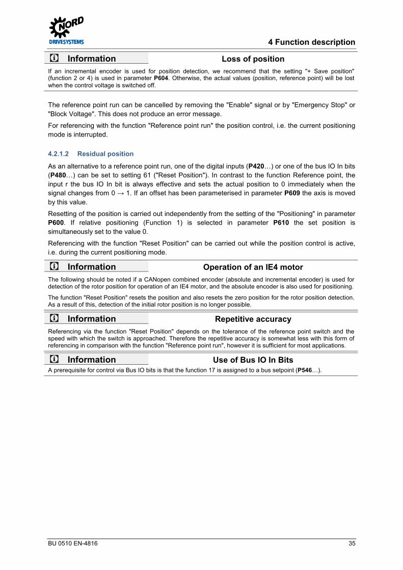
Information Loss of position If an incremental encoder is used for position detection, we recommend that the setting "+ Save position" (function 2 or 4) is used in parameter P604. Otherwise, the actual values (position, reference point) will be lost when the control voltage is switched off.
The reference point run can be cancelled by removing the "Enable" signal or by "Emergency Stop" or "Block Voltage". This does not produce an error message.
For referencing with the function "Reference point run" the position control, i.e. the current positioning mode is interrupted. Pos: 123 /Anleitungen/El ektr oni k/POSICON /4. Funktionsbeschr eibung/R eset Position @ 14\mod_1478075513018_388.docx @ 2300251 @ 4 @ 1
4.2.1.2 Residual position
As an alternative to a reference point run, one of the digital inputs (P420…) or one of the bus IO In bits (P480…) can be set to setting 61 ("Reset Position"). In contrast to the function Reference point, the input r the bus IO In bit is always effective and sets the actual position to 0 immediately when the signal changes from 0 → 1. If an offset has been parameterised in parameter P609 the axis is moved by this value.
Resetting of the position is carried out independently from the setting of the "Positioning" in parameter P600. If relative positioning (Function 1) is selected in parameter P610 the set position is simultaneously set to the value 0.
Referencing with the function "Reset Position" can be carried out while the position control is active, i.e. during the current positioning mode.
Information Operation of an IE4 motor The following should be noted if a CANopen combined encoder (absolute and incremental encoder) is used for detection of the rotor position for operation of an IE4 motor, and the absolute encoder is also used for positioning.
The function "Reset Position" resets the position and also resets the zero position for the rotor position detection. As a result of this, detection of the initial rotor position is no longer possible.
Information Repetitive accuracy Referencing via the function "Reset Position" depends on the tolerance of the reference point switch and the speed with which the switch is approached. Therefore the repetitive accuracy is somewhat less with this form of referencing in comparison with the function "Reference point run", however it is sufficient for most applications.
Information Use of Bus IO In Bits A prerequisite for control via Bus IO bits is that the function 17 is assigned to a bus setpoint (P546…).
Pos: 124 /Allgemein/Allgemeingültig e Module/---------Seitenumbr uch kompakt --------- @ 13\mod_1476369695906_0.docx @ 2265495 @ @ 1

POSICON positioning control – Supplementary manual for series SK 500E
36 BU 0510 EN-4816
Pos: 125 /Anleitungen/El ektr oni k/POSICON /4. Funktionsbeschr eibung/Lageer fassung mit Absol utwertgeber @ 14\mod_1478084693396_388.docx @ 2300325 @ 3 @ 1
4.2.2 Position detection with absolute encoders The absolute encoder transfers the actual position value to the frequency inverter in digital form. The position is always completely available in the absolute encoder and is also correct after displacement of the axis when the inverter is switched off.
A reference point run is therefore not necessary.
If an absolute encoder is connected, the parameter P604 "Encoder Type" must be parameterised to one of the absolute functions (Setting 1 or 5).
The resolution of the encoder is set in parameter P605.
If the absolute encoder is not mounted on the motor shaft the gear ratio between the motor and the absolute encoder must be parameterised. The number of revolutions of the encoder are converted into the number of motor revolutions in the frequency inverter with the aid of the parameters P607 "Speed ratio" and P608 "Reduction ratio.
nM = nG * Üb / Un nM: Number of revolutions of motor
nG:: Number of revolutions of encoder
Üb: Speed ratio (P607 [-02])
Un: Reduction ratio (P608 [-02])
Example The encoder is installed on the output side of the gear unit. The gear unit has a speed ratio of i = 26.3.
The following values are parameterised: P607 [-02] = 263
P608 [-02] = 10
Information Rotation direction The direction of rotation of the encoder must be the same as the direction of rotation of the motor. With a positive output frequency (clockwise rotation) the actual position value must increase. If the direction of rotation is not correct, this can be adjusted with a negative value in P607 "Speed Ratio".
With the aid of a value which can be parameterised in parameter P609 [-02]] "Offset Position" the zero point can be set to a different position to that which is determined by the reference point. The offset is applied after conversion of the encoder rotations to motor rotations. After changes to the speed ratio/reduction ratio (P607 [-02] and P608 [-02]) the offset position value must be entered again.
Information Maximum possible position The maximum possible position in parameter P615 "Maximum Position" results from the resolution of the encoder and the Speed Ratio/Reduction Ratio (P607 and P608). Under no circumstances can the maximum value exceed +/- 65535 (16Bit) rotations. Pos: 126 /Anleitungen/El ektr oni k/POSICON /4. Funktionsbeschr eibung/Ergänzende Ei nstellungen - C ANopen Absol utwertgeber @ 14\mod_1478086702582_388.docx @ 2300397 @ 4 @ 1
4.2.2.1 Supplementary settings – CANopen absolute encoders
The baud rate and the CAN address must be set on the encoder. For the assignment of the switches on the encoder, please refer to the manufacturer´s operating instructions.
The CAN address for the absolute encoder should be set in parameter P515[-01] "CAN Address" according to the following formula:
CAN address of absolute encoder = CAN address of frequency inverter (P515[-01]) + 1

4 Function description
BU 0510 EN-4816 37
The CAN baud rate set in the encoder must be identical to the parameter P514 "CAN Baud Rate" and all other participants in the bus system.
If parameterisation of the encoder is carried out via the frequency inverter, the transmission cycle for the absolute encoder position is simultaneously set via the baud rate.
For the operation of several CANopen absolute encoders on a bus system, e.g. for synchronous operation, different transmission cycle times can be set for the bus master and the CANopen absolute encoders.
With the parameter P552 "CAN Master Cycle Time" the cycle time for the CAN/CANopen master mode can be parameterised in Array [-01] and for the CANopen absolute encoder in Array [-02]. Care must be taken that the parameterised values are not lower than the values in the column for the minimum values of the actual cycle time. This valued depends on (P514).
P514 P552[-01]1) P552[-02]1) tZ2) Bus load3)
Bus Master CANopen encoder
[kBaud] [ms] [ms] [ms] [%]
10 50 20 10 42.5 20 25 20 10 21.2 50 10 10 5 17.0
100 5 5 2 17.0 125 5 5 2 13.6 250 5 2 1 17.0 500 5 2 1 8.5
10004) 5 2 1 4.25 1 Resulting factory setting 2 Minimum value for actual cycle time 3 Resulting from an encoder 4 Only for test purposes
Table 11: CANopen encoder cycle time dependent on the baud rate
The possible bus load in the system always depends on the real-time specific to the system. Very good results are achieved with a bus load less than 40 %. Under no circumstances should a bus load greater than 80 % be selected. For the estimation of the bus load, the other possible bus traffic (setpoint and actual values for the frequency inverters and other bus participants) should also be taken into account.
Additional explanations about the CAN interface can be obtained from Manual BU 2500. Pos: 127 /Anleitungen/El ektr oni k/POSICON /4. Funktionsbeschr eibung/Ergänzende Ei nstellungen - C ANopen Absol utwertgeber_Erg änzung_01_(Info 24 V) [BU 0510] @ 14\mod_1478096069892_388.docx @ 2300539 @ @ 1
Information 24 V DC CAN Bus supply In order to enable communication via the CAN bus, this must have a 24 V DC power supply ( BU 0500 or BU 0505). Pos: 130 /Anleitungen/El ektr oni k/POSICON /4. Funktionsbeschr eibung/Ergänzende Ei nstellungen - SSI Absolutwertg eber [BU 0510] @ 14\mod_1478086424066_388.docx @ 2300361 @ 4 @ 1
4.2.2.2 Supplementary settings - SSI absolute encoders
Protocol settings for SSI encoders are made in parameter P617.
In detail, this defines:
• The format in which the positions are transferred (binary / Gray code), • Whether a loss of voltage to the encoder is communicated to the frequency inverter ("Power Fail
Bit") and • Whether the encoder supports the communication version "Multiply Transmit" in which the position
is communicated a second time in a mirrored form in order to improve the reliability of the transfer. Pos: 131 /Anleitungen/El ektr oni k/POSICON /4. Funktionsbeschr eibung/R eferenzi eren eines Absol utwertgebers @ 14\mod_1478093578008_388.docx @ 2300468 @ 4 @ 1

POSICON positioning control – Supplementary manual for series SK 500E
38 BU 0510 EN-4816
4.2.2.3 Referencing an absolute encoder
Similarly to an incremental encoder, absolute encoders can be set to the value "0" or to the value which is set in parameter P609 [-02] "Offset Position" via the function "Reference point run" ( Section 4.2.1.1 "Approach reference point") and "Reset Position“ ( Section 4.2.1.2 "Residual position").
However, the precision of resetting the encoder position greatly depends on the actual speed of movement, the bus load, the baud rate and the type of encoder. Therefore it is urgently recommended that absolute encoders are only reset when they are at a standstill.
If both an incremental encoder and an absolute encoder are connected to the frequency inverter, both encoders are reset by performing the functions "Reference Point Run" or "Reset Position". Pos: 132 /Anleitungen/El ektr oni k/POSICON /4. Funktionsbeschr eibung/R eferenzi eren eines Absol utwertgebers_Ergänzung_01 [BU 0510] @ 14\mod_1478094539755_388.docx @ 2300504 @ @ 1
Information Restrictions for SSI encoders With an SSI encoder the position can only be changed via a position offset P609 [-03]]. Resetting ("Reset position" / "Reference Point Run") is not possible. Pos: 133 /Anleitungen/El ektr oni k/POSICON /4. Funktionsbeschr eibung/M anuelle Inbetriebnahme des C AN open Gebers @ 14\mod_1478097367735_388.docx @ 2300609 @ 4 @ 1
4.2.2.4 Manual commissioning of the CANopen absolute encoder
Normally, configuration of the encoder is carried out via the parameterisation of the frequency encoder.
Alternatively, the configuration can be carried out via a CAN bus master, which must be additionally integrated into the bus system.
If the encoder is set to the "Operational" state via this CAN bus master, the following settings can be made.
Function Parameter Note
Resolution 6001h and 6002h Value according to P605 Cycle time 6200h Recommendation: Value ≤ 20 ms (this setting influences the
response speed of the positioning control) Pos: 134 /Allgemein/Allgemeingültig e Module/---------Seitenumbr uch kompakt --------- @ 13\mod_1476369695906_0.docx @ 2265495 @ @ 1

4 Function description
BU 0510 EN-4816 39
Pos: 135 /Anleitungen/El ektr oni k/POSICON /4. Funktionsbeschr eibung/Geberüber wachung @ 14\mod_1478099832003_388.docx @ 2300645 @ 3 @ 1
4.2.3 Encoder monitoring If positioning control is activated (P600, setting ≠ 0) the function of a connected absolute encoder is monitored. A corresponding error message is generated if an error occurs. The last valid position remains visible in the frequency inverter (P601).
Monitoring is disabled if the positioning control is not active (P600, setting = 0). Therefore no error message is generated in case of an encoder error. The actual encoder position remains displayed in parameter P601.
If an absolute and incremental encoder are present, the positioning difference between the two encoders can be monitored with parameter P631 "Slip Error Abs/Inc". The maximum permissible position deviation between the absolute and the incremental encoder is specified by the value set in this parameter. The error message E14.6 is triggered if the maximum permissible deviation is exceeded.
• With parameter P630 "Position slip error" the actual position of the encoder is compared with the change in position which is calculated from the actual speed (estimated position). If the position difference exceeds the value which is set in P630 the error message E14.5 is triggered.
This method of slip error monitoring is subject to inaccuracies due to technical reasons, so that larger values must be set in case of longer movements. These values must be determined experimentally. On reaching a target position, the estimated position is replaced by the actual position value of the encoder in order to prevent the addition of errors.
• The permissible operating range can be restricted with the parameters P616 "Minimum Position" and P615 "Maximum Position". If the drive unit exceeds the permissible range, the error messages E14.7 or E14.8 are triggered.
Position setpoints which are larger than the values which are set in P616 or smaller than those which are set in P615 are automatically limited in the frequency inverter to the values which are set in the two parameters.
Position monitoring is not active if the value 0 is set in the relevant parameter or if the value 3, 4, 5 or 7 is set in parameter P604. Pos: 136 /Allgemein/Allgemeingültig e Module/---------Seitenumbr uch kompakt --------- @ 13\mod_1476369695906_0.docx @ 2265495 @ @ 1

POSICON positioning control – Supplementary manual for series SK 500E
40 BU 0510 EN-4816
Pos: 139 /Anleitungen/El ektr oni k/POSICON /4. Funktionsbeschr eibung/Positionier ungsmethode Linear oder Wegopti mal @ 14\mod_1478156842700_388.docx @ 2300689 @ 3 @ 1
4.2.4 Linear or optimised path positioning method The encoder used for positioning is activated via parameter P604 "Encoder type". Here, a differentiation is made between normal measurement (for "linear" systems) and "path optimised" measurement (for circulating systems).
In the function "Optimum Path" the multi-turn resolution of the encoder for the overflow point can be additionally limited via parameter P615 "Maximum Position". The multiturn resolution in rotations (1 rotation = 1,000 rev) is entered.
Select parameter P601 "Actual position" to check the setting and function of the encoder.
Encoder type Measuring method
Linear Optimised path
Incremental encoder 0 3 Incremental encoder with saving of the position in the FI 2 4 CANopen absolute encoders (only for encoders approved by NORD ( Section 3.2.1.1 "Approved CANopen absolute encoders (with bus cover)"))
1 5
CANopen absolute encoders for manual configuration ( Section 4.2.2.4 "Manual commissioning of the CANopen absolute encoder")
6 7 Pos: 140 /Anleitungen/El ektr oni k/POSICON /4. Funktionsbeschr eibung/Positionier ungsmethode Linear oder Wegopti mal_Ergänzung_01 (BU 0510) @ 14\mod_1478159156245_388.docx @ 2300797 @ @ 1
SSI encoders SK 540E and above 8 9 BISS encoders SK 540E and above 10 11 Hiperface encoders SK 540E and above 12 13 EnDat 2.1 encoder SK 540E and above 14 15
Table 12: Parameter P604 encoder type selection Pos: 141 /Allgemein/Allgemeingültig e Module/---------Seitenumbr uch kompakt --------- @ 13\mod_1476369695906_0.docx @ 2265495 @ @ 1

4 Function description
BU 0510 EN-4816 41
Pos: 142 /Anleitungen/El ektr oni k/POSICON /4. Funktionsbeschr eibung/Wegopti mal e Positionier ung @ 14\mod_1478159519602_388.docx @ 2300943 @ 4 @ 1
4.2.4.1 Optimised path positioning
For rotary platform applications, the individual positions are distributed around the circumference. Use of linear positioning is not recommended for this, as the frequency encoder would not always select the shortest path the to the selected position (e.g. starting position -0.375, set position + 0.375, see the following illustration "Linear path").
In contrast, positioning with path optimisation automatically selects the shortest path and therefore independently decides on the direction of rotation of the drive unit. Here, the drive unit passes over the overflow point of the relevant rotary encoder see the following illustration "Optimised path"). Here, the overflow point corresponds to half of a revolution of the encoder (single-turn application).
If the number of revolutions of the encoder deviates from the number of revolutions of the rotary platform application (multiturn application) the overflow point, i.e. the point at which the application (rotary platform) has rotated by one half must be determined. This value must be entered in parameter P615 "Maximum Position".
Information Overflow point in P615 For multiturn applications care must be taken that the overflow point is entered with a maximum precision of 3 places after the decimal point.
Deviations from this will result in a summation of errors after each overflow. In this case it is recommended that the encoder is referenced after each rotation of the system.
The zero point of a single-turn absolute encoder is determined by where it is mounted and can be varied via the parameter P609 [-02] "Offset Position". If an incremental encoder is used, specification of the zero position must by carried out either by a "Reference point run" or a "Reset Position". The zero position can be varied by means of an entry in parameter P609 [-01] "Offset Position".
Information Multi-turn absolute encoder A multi-turn absolute encoder can also be used as a single-turn absolute encoder. For this, the multiturn resolution (P605 [-01]) must be set to "0". Pos: 143 /Allgemein/Allgemeingültig e Module/---------Seitenumbr uch kompakt --------- @ 13\mod_1476369695906_0.docx @ 2265495 @ @ 1

POSICON positioning control – Supplementary manual for series SK 500E
42 BU 0510 EN-4816
Pos: 144 /Anleitungen/El ektr oni k/POSICON /4. Funktionsbeschr eibung/Wegopti mal e Positionier ung _Ergänzung _01_Beispi el für eine Singletur nanwendung @ 14\mod_1478169580383_388.docx @ 2301069 @ 5 @ 1
Examples for a "single-turn application"
The calculation of the overflow point of a single-turn application is made according to the following equation:
±nmax = 0.5 * Üb / Un nmax: Number of revolutions of motor = Overflow point (P615)
Üb: Speed ratio (P607 [-xx])1)
Un: Reduction ratio (P608 [-xx])1)
1) Depending on the encoder or absolute encoder used for positioning control: [-xx] = [-02]
Example 1 The encoder, an absolute encoder, is mounted on the motor shaft (speed and reduction ratio = "1").
±nmax = 0.5 * 1 / 1 = 0.5 revolutions
The following values are parameterised: P607 [-02] = 1 P608 [-02] = 1 P615 = = 0.5
Linear path Path optimised movement
Figure 1: Rotary platform positioning with a single-turn application
Information Parameterisation of P615 In this case (single-turn application, encoder on the motor shaft) P615 can also remain in the factory setting (setting 0).
Example 2
The encoder, an absolute encoder is installed on the output side of the gear unit. The gear unit has a speed ratio of i = 26.3.
±nmax = 0.5 * 263 / 10 = 13.15 revolutions
The following values are parameterised: P607 [-02] = 263 P608 [-02] = 10 P615 = = 13.15
Pos: 145 /Allgemein/Allgemeingültig e Module/---------Seitenumbr uch kompakt --------- @ 13\mod_1476369695906_0.docx @ 2265495 @ @ 1
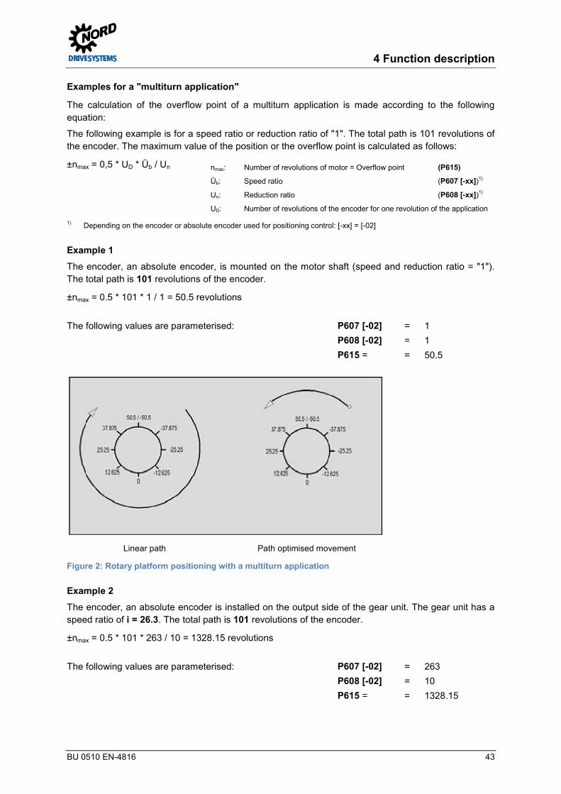
4 Function description
BU 0510 EN-4816 43
Pos: 146 /Anleitungen/El ektr oni k/POSICON /4. Funktionsbeschr eibung/Wegopti mal e Positionier ung _Ergänzung _02_Beispi el für eine M ultiturnanwendung @ 14\mod_1478171703235_388.docx @ 2301105 @ 5 @ 1
Examples for a "multiturn application"
The calculation of the overflow point of a multiturn application is made according to the following equation:
The following example is for a speed ratio or reduction ratio of "1". The total path is 101 revolutions of the encoder. The maximum value of the position or the overflow point is calculated as follows:
±nmax = 0,5 * UD * Üb / Un nmax: Number of revolutions of motor = Overflow point (P615)
Üb: Speed ratio (P607 [-xx])1)
Un: Reduction ratio (P608 [-xx])1)
UD: Number of revolutions of the encoder for one revolution of the application
1) Depending on the encoder or absolute encoder used for positioning control: [-xx] = [-02]
Example 1 The encoder, an absolute encoder, is mounted on the motor shaft (speed and reduction ratio = "1"). The total path is 101 revolutions of the encoder.
±nmax = 0.5 * 101 * 1 / 1 = 50.5 revolutions
The following values are parameterised: P607 [-02] = 1 P608 [-02] = 1 P615 = = 50.5
Linear path Path optimised movement
Figure 2: Rotary platform positioning with a multiturn application
Example 2 The encoder, an absolute encoder is installed on the output side of the gear unit. The gear unit has a speed ratio of i = 26.3. The total path is 101 revolutions of the encoder.
±nmax = 0.5 * 101 * 263 / 10 = 1328.15 revolutions
The following values are parameterised: P607 [-02] = 263 P608 [-02] = 10 P615 = = 1328.15
Pos: 147 /Allgemein/Allgemeingültig e Module/---------Seitenumbr uch kompakt --------- @ 13\mod_1476369695906_0.docx @ 2265495 @ @ 1

POSICON positioning control – Supplementary manual for series SK 500E
44 BU 0510 EN-4816
Pos: 148 /Anleitungen/El ektr oni k/POSICON /4. Funktionsbeschr eibung/Soll wertvorgabe @ 14\mod_1478249393869_388.docx @ 2301369 @ 2 @ 1
4.3 Setpoint specification Setpoints can be specified as follows:
• Digital inputs or Bus IO In Bits as absolute position by means of the position array • Digital inputs or Bus IO In Bits as relative position by means of the position increment array • Bus setpoint value
It is irrelevant whether an incremental or an absolute encoder is used for position detection, i.e. for determination of the actual position. Pos: 149 /Anleitungen/El ektr oni k/POSICON /4. Funktionsbeschr eibung/Absol ute Soll posi tion (Positi onsarray) über Digitalei ngänge / BUS IO In Bi ts @ 14\mod_1478251452427_388.docx @ 2301405 @ 3 @ 1
4.3.1 Absolute set position (position array) via digital inputs / BUS IO Bits Positioning with absolute set positions is primarily used if certain fixed positions exist, which are approached by the drive unit ("move to position x"). This includes e.g. shelf picking equipment.
In parameter P610 "Setpoint Mode", positions stored in parameter P613can be selected via the digital inputs of the frequency inverter or Bus IO In Bits using Function 0 = "Position Array".
The position numbers result from the binary value. A position setpoint value (P613) can be parameterised for each position number. The position setpoint can be determined and entered either via a control panel (ControlBox or ParameterBox) or with the "NORD CON" PC parameterisation and diagnostic software. Alternatively, a digital input or BUS IO In Bit must be parameterised to function 24 "Teach-In". Triggering of this digital function results in the adoption of the actual position in the arrays of parameter P613 ( Section 4.4 ""Teach - In“ – Function for saving positions")
With function 62 "Sync. position array" (digital inputs or BUS I/O In Bits) it is possible to preselect a saved position without immediate movement to this position. The preselected position is only adopted as a setpoint and moved to after the input is set to "1" ( Section 4.3.3.2 "Relative set position (position increment array) via field bus").
If the absolute setpoint position is specified via Bus IO In Bits, the position number results from bits 0...5 of the serial interface. For this, a bus setpoint value (P546…, "Function Bus - Setpoints") must be set in the setting 17 "Bus IO In Bits 0-7" and the functions assigned to the corresponding bits under P480 "Function Bus I/O In Bits".
Information Addition of setpoints Position setpoints from different sources are added to each other. I.e. the frequency inverter adds all of the individual setpoints which are specified for it to form a resulting setpoint and moves to this target (e.g.: setpoint via digital input + setpoint via bus). Pos: 150 /Allgemein/Allgemeingültig e Module/---------Seitenumbr uch kompakt --------- @ 13\mod_1476369695906_0.docx @ 2265495 @ @ 1

4 Function description
BU 0510 EN-4816 45
Pos: 151 /Anleitungen/El ektr oni k/POSICON /4. Funktionsbeschr eibung/R elati ve Sollpositi on (Positionsi nkrementarr ay) über Digital eingänge / BUS IO In Bits @ 14\mod_1478255969156_388.docx @ 2301441 @ 3 @ 1
4.3.2 Relative set position (position increment array) via digital inputs / BUS IO Bits Positioning with relative set positions is primarily used if there are no fixed positions, but rather relative positions which are approached by the drive unit ("move by x increments"). This includes endless axes.
As with fixed positions, the position increments are also defined via parameter P613. However, the number of available positions is limited to the first 6 entries (P613 [-01]…[-06]).
If the input signal changes from "0" to "1" the value of the selected element is added to the setpoint position. The values can be positive or negative, so that a return to the starting position is also possible. The addition is carried out with each positive signal flank, regardless of whether or not the inverter is enabled. A multiple of the parameterised increment can be specified with several consecutive pulses to the allocated input. The pulse width and the width of the pauses between pulses must be at least 10 ms.
If the relative setpoint position is specified via Bus IO In Bits, the position increment results from bits 0...5 of the serial interface. For this, a bus setpoint value (P546…, "Function Bus - Setpoints") must be set in the setting 17 "Bus IO In Bits 0-7" and the functions assigned to the corresponding bits under P480 "Function Bus I/O In Bits". Pos: 152 /Allgemein/Allgemeingültig e Module/---------Seitenumbr uch kompakt --------- @ 13\mod_1476369695906_0.docx @ 2265495 @ @ 1

POSICON positioning control – Supplementary manual for series SK 500E
46 BU 0510 EN-4816
Pos: 153 /Anleitungen/El ektr oni k/POSICON /4. Funktionsbeschr eibung/Bussoll werte @ 14\mod_1478505496031_388.docx @ 2301480 @ 3 @ 1
4.3.3 Bus setpoints Transfer of the setpoint can be carried out via various field bus systems. The position can be specified in terms of rotations or increments.
A rotation of the motor then corresponds to a resolution of 1/1000 rotation or 32768 increments.
The source of the bus setpoint via the relevant field bus must be selected in parameter P510 "Setpoint Source". The position setpoints to be transferred via the bus must be set in parameters P546 "Function Bus Setpoints"
The High and Low words should be used in order to utilise the entire positioning range (32 Bit position).
Example One motor rotation (See value P602) = 1.000 revolutions = Bus setpoint 1000dec Pos: 154 /Anleitungen/El ektr oni k/POSICON /4. Funktionsbeschr eibung/Absol ute Soll posi tion (Positi onsarray) über den Feldbus @ 14\mod_1478507679124_388.docx @ 2301516 @ 4 @ 1
4.3.3.1 Absolute set position (position array) via field bus
If the "Bus" setting 3 is parameterised in parameter P610 "Setpoint Mode", the setpoint specification is exclusively made via a field bus system. The setting of the field bus system is parameterised in parameter P509 "Control word source". For the "Bus" setting, the functions of the digital inputs as well as the Bus IO In Bits for the specification of the position from parameter P613 "Position" / position array elements are not enabled. Pos: 155 /Anleitungen/El ektr oni k/POSICON /4. Funktionsbeschr eibung/R elati ve Sollpositi on (Positionsi nkrementarr ay) über den Feldbus @ 14\mod_1478507955625_388.docx @ 2301588 @ 4 @ 1
4.3.3.2 Relative set position (position increment array) via field bus
If the "Bus" setting 4 for "Bus increment" is parameterised in parameter P610 "Setpoint Mode", the setpoint specification for the relative position is made via a field bus system. The setting of the field bus system is parameterised in parameter P509 "Control word source". Adoption of the setpoint is made on a change of flank from "0" to "1" using function 62 "Sync. position array“ (P420 or P480). Pos: 156 /Allgemein/Allgemeingültig e Module/---------Seitenumbr uch kompakt --------- @ 13\mod_1476369695906_0.docx @ 2265495 @ @ 1

4 Function description
BU 0510 EN-4816 47
Pos: 157 /Anleitungen/El ektr oni k/POSICON /4. Funktionsbeschr eibung/„Teach – In“ – Funkti on zur Speicherung von Positi onen @ 14\mod_1478509532831_388.docx @ 2301624 @ 2 @ 1
4.4 "Teach - In“ – Function for saving positions As an alternative to the direct input, parameterisation of the absolute setpoint position (position array) can also be carried out via the function "Teach-In".
Two inputs are required for "Teach- In" via digital inputs or Bus IO In Bits. One input, or one of the parameters P420… or 480must be parameterised to function 24 "Teach-In" and a further input must be parameterised to function 25 "Quit Teach-In".
"Teach-In" is started with the "1" signal to the relevant input and remains enabled until the signal is cancelled again.
On a change from "0" to "1" of the "Quit Teach-In" signal, the actual position value is saved as the setpoint position in parameter P613 "Position". The position number or the position array element or the position increment array is specified via the position specification (bit 0 to 5 position / increment array) of the digital inputs or Bus IO In Bits in parameter P420 or P480 with one of the functions (55 to 58).
If no input is accessed (corresponds to position 0) the position number is generated via an internal counter. The counter is increased after the adoption of each position.
Example • Start "Teach-In" without position specification:
The internal counter has the value 1, • Triggering of the function "Quit- Teach-In"
– Saving of the actual position in the first storage location (P613 [-01]) – Increase of the internal counter to 2
• Triggering of the function "Quit- Teach-In" – Saving of the actual position in the first storage location (P613 [-02]) – Increase of the internal counter to 3
• etc. As soon as a position is addressed via the digital inputs, the counter is set to this position.
As long as "Teach-In" is enabled, the frequency inverter can be controlled with enable signals and frequency setpoints (identical to parameter P600 "Position Control" = "Off").
The function "Teach-In" can also be implemented via a serial interface or the Bus IO In Bits. For this, a bus setpoint value (P546…) "Function Bus - Setpoints") must be set in the setting "Bus IO In Bits 0...7" and the functions assigned to the corresponding bits under P4800 "Function Bus I/O In Bits" on the relevant bus. Pos: 158 /Allgemein/Allgemeingültig e Module/---------Seitenumbr uch kompakt --------- @ 13\mod_1476369695906_0.docx @ 2265495 @ @ 1

POSICON positioning control – Supplementary manual for series SK 500E
48 BU 0510 EN-4816
Pos : 159 /Anleitungen/El ektr oni k/POSICON /4. F unktionsbeschr eibung/Ü bersetzungsver hältnis der Soll- und Ist werte @ 14\mod_1478512826655_388.docx @ 2301660 @ 2 @ 1
4.5 Speed ratio of setpoint and actual values Position values are based on the number of rotations of the motor. If a different reference value is required, with the aid of parameter P607 [03] the "Speed Ratio" and P608 [03] the "Reduction Ratio" can be converted into a different unit. No values after the decimal point can be entered in the parameters "Speed Ratio" and "Reduction Ratio". In order to achieve greater precision, the two values should each be multiplied by the same factor, which should be as large as possible. The product must not exceed the value 65000, i.e. the factor must not be too large.
Example Lifting gear • Unit in [cm]• Gear unit: i = 26.3• Drum diameter: d = 50.5 cm• Factor: 100 (selected)
revolutioncmcm
ospeed ratiPuction speed redP 6
263015865
1003,2610065,158
3,265,50
]03[607]03[608
≈=××
=×
=−
− p
The required unit can be selected in parameter P640 "Unit Pos. Value". Accordingly, in this example, parameter P640 must be parameterised to the function 4 = "cm". Pos: 160 /Allgemein/Allgemeingültig e Module/---------Seitenumbr uch kompakt --------- @ 13\mod_1476369695906_0.docx @ 2265495 @ @ 1

4 Function description
BU 0510 EN-4816 49
Pos: 161 /Anleitungen/El ektr oni k/POSICON /4. Funktionsbeschr eibung/Lageregel ung @ 14\mod_1478513400378_388.docx @ 2301696 @ 2 @ 1
4.6 Position control Pos: 162 /Anleitungen/El ektr oni k/POSICON /4. Funktionsbeschr eibung/Lageregel ung - Varianten der Posi tionier ung (P600) @ 14\mod_1478514186449_388.docx @ 2301732 @ 3 @ 1
4.6.1 Position control - Position control variants (P600) Four different positioning variants are possible.
• Linear ramp with maximum frequency (P600, setting 1)
The acceleration is linear. The speed of constant travel is always carried out with the "Maximum Frequency" set under parameter P105. The acceleration time (P102) and the deceleration time (P103) are relative to the maximum frequency (P105). Example
P105 = 50 Hz, P102 = 10 s; Ramp time = P102 = 10 s The drive unit accelerates from 0 Hz to 50 Hz in 10 s.
• Linear ramp with setpoint frequency (P600, setting 2)
The acceleration is linear. The speed of constant travel is specified via the setpoint frequency. This can be changed via the analogue input or via a bus setpoint value. The acceleration time (P102) and the deceleration time (P103) are relative to the maximum frequency (P105). Example
P105 = 50 Hz, P102 = 10 s, setpoint 50 % (25 Hz); Ramp time = P102 * 0,5 = 5 s The drive unit accelerates from 0 Hz to 25 Hz in 5 s.
• S ramp with maximum frequency (P600, setting 3)
The speed of constant travel is always carried out with the "Maximum Frequency" set under parameter P105. However, in positioning operation the frequency ramps can be operated as S ramps. Compared with conventional linear frequency increases (or decreases), according to the acceleration time (or deceleration time) a gentle rounding (without jerking) is performed to change from a static state to acceleration or braking. Also, when the final speed is attained, the acceleration or deceleration is slowly reduced. The S ramp always corresponds to a rounding of 100 % and only applies, when positioning is also performed. The effective ramp time is doubled by S ramping. The acceleration time (P102) and the deceleration time (P103) are relative to the maximum frequency (P105). Example
P105 = 50 Hz, P102 = 10 s; Ramp time = P102 * 2 = 10 s * 2 = 20 s The drive unit accelerates from 0 Hz to 50 Hz in 20 s.
The S ramp function is disabled during a reference point run.

POSICON positioning control – Supplementary manual for series SK 500E
50 BU 0510 EN-4816
• S ramp with setpoint frequency (P600, setting 4)
The speed of constant travel is specified via the setpoint frequency. However, in positioning mode, the frequency ramps are operated as S ramps (see previous paragraph). The setpoint frequency can be changed via the analogue input or via a bus setpoint value. The acceleration time (P102) and the deceleration time (P103) are relative to the maximum frequency (P105) and are calculated as follows:
Ramp time * Acceleration time / Maximum frequency
Example
P105 = 50 Hz, P102 = 10 s, Setpoint 50 % = Setpoint frequency 25 Hz; Ramp time = 2 * P102 * √(Setpoint frequency / P105) = 2 * 10 s * √( 25 Hz / 50 Hz) The drive unit accelerates from 0 Hz to 25 Hz in 14.1 s.
The S ramp function is disabled during a reference point run.
Information Setpoint frequency or ramp times During a positioning movement, changes of the setpoint frequency or ramp times do not affect the acceleration or the final speed of the drive unit. The new values are only adopted and included in the calculation for the next positioning movement after the target position has been reached.
Information P106 - Ramp rounding Parameter P106 "Ramp rounding" is disabled if position control is enabled (P600, setting ≠ 0).
Information Effective ramp time The actual or effective ramp time may deviate from the parameterised values if the load limits are reached, or in case of small movement paths. Pos: 163 /Allgemein/Allgemeingültig e Module/---------Seitenumbr uch kompakt --------- @ 13\mod_1476369695906_0.docx @ 2265495 @ @ 1

4 Function description
BU 0510 EN-4816 51
Pos: 164 /Anleitungen/El ektr oni k/POSICON /4. Funktionsbeschr eibung/Lagerergel ung - Funkti onsweise @ 14\mod_1478515892877_388.docx @ 2301893 @ 2 @ 1
4.7 Position control – Method of operation The position control functions as a P- feedback loop. The set position and the actual position are continuously compared with each other. The setpoint frequency is formed by the multiplication of this difference with parameter P611 "Position Control P". This value is then limited to the "Maximum Frequency" parameterised in parameter P105.
A "Path distance" is calculated from the "Braking Time" parameterised in parameter P103 and the current speed. Without taking the braking time into account in the distance calculation, the speed would normally be reduced too late and the set position would be exceeded. Exceptions to this are highly dynamic applications with extremely short braking and starting times and applications in which only very small path increments are specified.
A so-called target window can be specified in parameter P612 "Target window value". Within the target window the setpoint frequency is limited to the frequency set in parameter P104 "Minimum Frequency" and enables a type of "slow running". This frequency can not fall below 2 Hz. The "Slow running" function is especially recommended for applications with greatly varying loads, or if the drive unit has to be operated without speed control (P300 = "Off").
Parameter P612 defines the starting point and therefore the distance for the "slow running" which ends at the set position. It does not have any effect on the output message "Position reached" (e.g. parameter P434).
A = Acceleration time
B = Travel with maximum frequency
C = Deceleration time
D = Time determined by the "Target window value" (P612)
1 = Position controller P
2 = Travel with minimum frequency
Figure 3: Position control sequence Pos: 165 /Allgemein/Allgemeingültig e Module/---------Seitenumbr uch kompakt --------- @ 13\mod_1476369695906_0.docx @ 2265495 @ @ 1

POSICON positioning control – Supplementary manual for series SK 500E
52 BU 0510 EN-4816
Pos: 166 /Anleitungen/El ektr oni k/POSICON /4. Funktionsbeschr eibung/R estwegpositi oni erung @ 14\mod_1478852276300_388.docx @ 2303121 @ 2 @ 1
4.8 Remaining path positioning Remaining path positioning is a variant of position control. With this, the drive unit changes from normal speed regulation to position control on receipt of a trigger pulse and then moves for a defined distance before coming to a standstill.
Relevant parameters for remaining path positioning
Parameter Value Meaning
P420… or P480 78 Remaining path trigger P610 10 Remaining path positioning P613 [-01] xx Remaining path if the drive is enabled with "Enable right" P613 [-02] xx Remaining path if the drive is enabled with "Enable left"
Sequence for remaining path positioning After enabling, the drive unit first moves with the setpoint frequency until there is a positive flank 0 1 from the sensor at the input with function "Trigger remaining path". The drive unit then switches to position control and then moves for the distance which has been programmed in parameter P613 [-01] or [-02]. If a position setpoint is sent to the inverter via the bus, this is added to the value in P613 [-01] or [-02]. If no value is entered in P613 [-01] or [-02] the bus setpoint represents the relative remaining path.
After reaching the target position the drive unit remains in this position.
A new pulse at the input with the function "Trigger remaining path" triggers the function again. The drive unit then moves for a further remaining distance. It does not matter whether the drive unit is already stationary in its target position or is still running.
The following options are available for starting a new remaining path positioning (start in setpoint mode):
• Stop the drive (cancel enabling) and re-enable the drive, or • Trigger Digital In function 62 "Sync. position array" (via digital input P420…, or BUS IO In Bit P480)
The status message "Position reached" only appears after completion of the remaining path positioning. During constant movement with the setpoint frequency, the status message "Position reached" is disabled.
The precision of remaining path positioning depends on the jitter of the response time, the speed, as well as on the initiator which is used. The jitter of the response time of a digital input is typically 1 - 2 ms. The position error therefore corresponds to the distance which is travelled at the particular speed during the jitter time.
Remaining path positioning is always carried out with a linear ramp. Any S ramps which are set do not have an effect. If a position limit is enabled (P615 / P616), this is taken into account in the constant running. Pos: 167 /Allgemein/Allgemeingültig e Module/---------Seitenumbr uch kompakt --------- @ 13\mod_1476369695906_0.docx @ 2265495 @ @ 1

4 Function description
BU 0510 EN-4816 53
Pos: 168 /Anleitungen/El ektr oni k/POSICON /4. Funktionsbeschr eibung/Gleichlauf/!Gleichlaufreg elung @ 14\mod_1478592362656_388.docx @ 2302189 @ 2 @ 1
4.9 Synchronous control Positioning or synchronised running depends on the fact that all of the relevant devices communicate via a common bus (CANopen / CAN bus). The master device transmits its "actual position Position" and its "actual setpoint speed after frequency ramp" to the slave device(s). The slave devices use the speed as specified and compensate the remainder via the position control. The transmission time for the actual speed and position from the master to the slave devices generates an angular or positional deviation which is proportional to the speed of travel.
ΔP = n[rpm] / 60 * Cycle time [ms] / 1000
With 1500 rpm and a transmission time of approx. 5ms, a deviation of 0.125 rotations or 45° results. This deviation is to some extent adjusted for by an appropriate compensation by the slave. However, there is still a jitter (fluctuation) of approx. 1ms in the cycle time, which cannot be compensated for. In the case selected, there remains an angular error of approx 9°. This only applies if a CANopen / CAN bus- baud rate of at least 100kBaud is used to couple the two drive units. Coupling with a lower baud rate increases the deviation considerably and is therefore not recommended.
Coupling of the drive units via CANopen enables the simultaneous operation of CANopen absolute encoders. However, care must be taken that this network does not contain more than 5 slave frequency inverters. This is the only way to ensure that the bus load remains below 50% and a deterministic behaviour remains ensured. Pos: 169 /Allgemein/Allgemeingültig e Module/---------Seitenumbr uch kompakt --------- @ 13\mod_1476369695906_0.docx @ 2265495 @ @ 1

POSICON positioning control – Supplementary manual for series SK 500E
54 BU 0510 EN-4816
Pos: 170 /Anleitungen/El ektr oni k/POSICON /4. Funktionsbeschr eibung/Gleichlauf/Kommuni kationseinstell ung en_01 @ 14\mod_1478621182729_388.docx @ 2302566 @ 3 @ 1
4.9.1 Communication settings Establishment of communication between the master and the slave via CANopen requires the following settings:
Master frequency inverter
Parameter Value Meaning
P502 [-01] 20 Setpoint frequency after the frequency ramp 1) P502 [-02] 15 Actual position in incremental High word 2) P502 [-03] 10 Actual position in incremental Low word 2) P503 3 CANopen P505 0 0.0 Hz P514 5 250 kBaud (at least 100 kBaud should be set) P515 [-03] P515Slave [-02] Broadcast – Master – Address 1) If the enable signal is not also transferred from the master to the slave, i.e. the slave is only enabled in one direction, but the master rotates
in both directions the function "Actual frequency without slip guide value " 21“ must be used instead of "Setpoint frequency after frequency ramp "20".
2) The actual position must be transferred to the slave(s) in the setting ".... in increments". Otherwise the number of transmission time errors is increased.
Slave frequency inverter
Parameter Value Meaning
P510 [-01] 10 Main setpoint from CANopen - Broadcast P510 [-02] 10 Aux. setpoint from CANopen - Broadcast P505 0 0.0 Hz P514 P514Master Setting according to the value in the master P515 [-02] P515Master [-03] Broadcast – Slave – Address P546 [-01] / P546 4 Frequency addition 1) P546 [-02] / P547 24 Setpoint position in inc. High word P546 [-03] / P548 23 Setpoint position in inc. Low word P600 1 or 2 Position control ON 2) P610 2 Synchronous operation 1) The setting "Frequency addition" is necessary in order to optimise the calculation of the speed behaviour and to minimise control deviations
to the master. However, this greatly restricts the possibility of compensating for any position deviations from the master at maximum speed. 2) Both settings are possible. In synchronous mode positioning is always carried out with the maximum possible frequency.
Pos: 171 /Allgemein/Allgemeingültig e Module/---------Seitenumbr uch kompakt --------- @ 13\mod_1476369695906_0.docx @ 2265495 @ @ 1

4 Function description
BU 0510 EN-4816 55
Pos: 172 /Anleitungen/El ektr oni k/POSICON /4. Funktionsbeschr eibung/Gleichlauf/Kommuni kationseinstell ung en_02 [BU 0510] @ 14\mod_1478690089772_388.docx @ 2302609 @ @ 1
Establishment of communication between the master and slave via the CAN Bus is also possible and requires the following settings.
Master frequency inverter
Parameter Value Meaning
P502 [-01] 20 Setpoint frequency after the frequency ramp 1) P502 [-02] 15 Actual position in incremental High word 2) P502 [-03] 10 Actual position in incremental Low word 2) P503 2 CAN P505 0 0.0 Hz P514 5 250 kBaud (at least 100 kBaud should be set) P515 [-01] 0 Address 0 ( Section "Monitoring functions – Master
switch-off") 1) If the enable signal is not also transferred from the master to the slave, i.e. the slave is only enabled in one direction, but the master rotates
in both directions the function "Actual frequency without slip guide value "21“ must be used instead of "Setpoint frequency after frequency ramp "20".
2) The actual position must be transferred to the slave(s) in the setting ".... in increments". Otherwise the number of transmission time errors is increased.
Slave frequency inverter
Parameter Value Meaning
P510 [-01] 9 Main setpoint value of CAN - Broadcast P510 [-02] 9 Aux. setpoint value of CAN - Broadcast P505 0 0.0 Hz P514 P514Master Setting according to the value in the master P515 [-01] 128 Address 128 ( Section "Monitoring functions –
Master switch-off") P546 [-01] / P546 4 Frequency addition 1) P546 [-02] / P547 24 Setpoint position in inc. High word P546 [-03] / P548 23 Setpoint position in inc. Low word P600 1 or 2 Position control ON 2) P610 2 Synchronous operation 1) The setting "Frequency addition" is necessary in order to optimise the calculation of the speed behaviour and to minimise control deviations
to the master. However, this greatly restricts the possibility of compensating for any position deviations from the master at maximum speed. 2) Both settings are possible. In synchronous mode positioning is always carried out with the maximum possible frequency.
Pos: 173 /Allgemein/Allgemeingültig e Module/---------Seitenumbr uch kompakt --------- @ 13\mod_1476369695906_0.docx @ 2265495 @ @ 1

POSICON positioning control – Supplementary manual for series SK 500E
56 BU 0510 EN-4816
Pos: 174 /Anleitungen/El ektr oni k/POSICON /4. Funktionsbeschr eibung/Gleichlauf/Ei nstellung Rampenzeit und Maxi malfreq wuenz am Slave @ 14\mod_1478691025699_388.docx @ 2302645 @ 3 @ 1
4.9.2 Ramp time and maximum frequency settings on the slave In order for the slave to be able to perform the control, the ramp times should be selected somewhat smaller than for the master and the maximum frequency should be selected somewhat higher.
Slave frequency inverter
Parameter Value
P102 0.5 .. 0,95 * P102Master P103 0.5 .. 0,95 * P103Master P105 1.05 .. 1.5 * P102Master P410 0 P411 P105Master Pos: 175 /Anleitungen/El ektr oni k/POSICON /4. Funktionsbeschr eibung/Gleichlauf/Ei nstellung Drehzahlregl er und Lager egler @ 14\mod_1478694477580_388.docx @ 2302681 @ 3 @ 1
4.9.3 Setting the speed and position controls 1. Set the speed (P300 ff) and position controller (P600 ff) independently of each other in all devices. 2. Commissioning the "Synchronous mode" position control.
The controller settings depend greatly on the characteristics of the drive unit, the drive application and the load conditions. They can therefore not be planned in advance and must be set or optimised experimentally on the system.
In principle, better dynamic results can usually be achieved with "sharper" controller settings. However, for optimum position control, care should be taken that there is a rather moderate setting of the I-component in the speed controller.
The speed control should be set for a slight overshoot. This results in a P-component which is as high as possible (until noises occur at low speeds), and a rather moderate I-component..
The setting of the torque limits and the selected ramps must be made so that the drive can always follow the ramp.
Information Controller settings Detailed information about the setting and optimisation of speed and position controllers can be found on our website www.nord.com in the application guidelines AG 0100 and AG 0101. Pos: 176 /Allgemein/Allgemeingültig e Module/---------Seitenumbr uch kompakt --------- @ 13\mod_1476369695906_0.docx @ 2265495 @ @ 1

4 Function description
BU 0510 EN-4816 57
Pos: 177 /Anleitungen/El ektr oni k/POSICON /4. Funktionsbeschr eibung/Gleichlauf/Berücksichtigung ei ner Ü bersetzung zwischen M aster und Slave @ 14\mod_1478697845744_388.docx @ 2302717 @ 355 @ 1
4.9.4 Taking a speed ratio between master and slave into account
Setting a fixed speed ratio
A speed ratio between the master and the slave can be taken into account via the parameters P607 "Speed Ratio" and P608 "Reduction Ratio".
The speed ratio is entered into the arrays of the unused encoder. (exception SK 54xE: P607[-05] / P608[-05])
NSlave = P607 [-xx] / P608 [-xx] * NMaster
P105Slave = P607 [-xx] / P608 [-xx] * NMaster * 1.05…1.5
Setting a variable speed ratio
With the use of an analogue input, the speed ratio between the master and the slave can be continuously varied between -200% and a maximum of 200% of the speed of the master.
For this, the relevant analogue input (P400…) must be set to function 47 "Gearing speed ratio". With the adjustment of the analogue input (P402… / P403…) this is scaled according to the existing requirements. Negative values cause a change in the direction of rotation.
It is possible to adjust the speed ration "online", i.e. during running. However, it should be noted that the "Position slip error" during adjustment can have considerably larger values than in normal synchronous operation. The reason for this is the necessary adjustment to the new speed and must be taken into account as necessary by changing the permissible slip error (in parameter P630 "Position slip error". Pos: 178 /Allgemein/Allgemeingültig e Module/---------Seitenumbr uch kompakt --------- @ 13\mod_1476369695906_0.docx @ 2265495 @ @ 1

POSICON positioning control – Supplementary manual for series SK 500E
58 BU 0510 EN-4816
Pos: 179 /Anleitungen/El ektr oni k/POSICON /4. Funktionsbeschr eibung/Gleichlauf/Über wachungs funkti onen_01 @ 14\mod_1478702983333_388.docx @ 2302755 @ 3 @ 1
4.9.5 Monitoring functions Pos: 180 /Anleitungen/El ektr oni k/POSICON /4. Funktionsbeschr eibung/Gleichlauf/Über wachungs funkti onen_02_Erreichbare Genauigkeiten / Lageüber wachung @ 14\mod_1478703014566_388.docx @ 2302791 @ 4 @ 1
4.9.5.1 Achievable precision of position monitoring
The deviation between the master and the slave can be monitored by the slave with the status message "Position Reached" (e.g.: P434, setting 21). The achievable precision of this message and therefore the deviation of the master and slave drives depends on several factors. Here, in addition to the settings of the speed control and the position control, the path, i.e. the drive or the mechanics of the system, play a decisive role.
The minimum value of the achievable precision is however determined by the type of transmission. A deviation of at least 0.1 rotations should be expected. In practice, a value of more than 0.25 motor rotations should be planned for. The message "Position reached" is deleted if the value which is set in P625 "Output hysteresis" is exceeded or the difference between the specified and actual speed exceeds 2 Hz + P104. The minimum frequency for the slave can be calculated with the following formula:
P104 = 0.25 ... 1,0 * (P625 [Rotation] * 4,0 Hz * P611 [%]) – 2 Hz
With a permissible deviation of one rotation and a value in "Position controller P" (P611) of 5 % this results in a speed component for the position control of 20 Hz. If P104 is set to a considerably lower value, the status message is determined by the exceeding of the speed by the slave and not by the maximum deviation in position. This especially applies, the shorter the ramp times are set for the slave. Pos: 181 /Anleitungen/El ektr oni k/POSICON /4. Funktionsbeschr eibung/Gleichlauf/Über wachungs funkti onen_03_M asterabschaltung bei Slave – Fehler oder Lageschleppfehl er @ 14\mod_1478703857032_388.docx @ 2302827 @ 4 @ 1
4.9.5.2 Master switch-off on slave error or position slip error
With a master – slave coupling, errors in the master are automatically dealt with by communication of the position to the slave. As long as the communication is intact, a synchronisation fault is ruled out in case of an error in the master. The slave regulates to the position of the master without hindrance.
However, if the slave cannot follow the specified position of the master, or if the slave goes into an error state, corresponding information and an associated response by the master is required. This can be either via a higher level control unit or by implementing a second communication channel between the slave and the master. For this, the slave frequency inverter sends the master the bit "Position reached" and/or "Fault", each as a Bus IO Bit. The master can use this signal, e.g. to initiate an emergency stop, or to change to the "Fault" state and shut down.
Example • A fault occurs in the slave. The device changes to the operating state "Fault". As a result of this the
master immediately changes to the operating state "Fault". • The slave cannot follow the master due to mechanical jamming. The parameterised slip error limit
is exceeded, i.e. the status message "Position reached" on the slave is deleted). The master stops. The master can only be re-enabled if the slave device is again within the specified tolerance.

4 Function description
BU 0510 EN-4816 59
The following settings are required in order to set up the necessary second communication channel:
Master frequency inverter Parameter Value Meaning P426 P103Master Deceleration time fault with slave P460 0 Watchdog time = 0 “Customer error” P480 [-01] 18 Watchdog P480 [-02] 11 Emergency stop P510 [-02] 10 CANopen - Broadcast P546 17 Bus IO In Bit
Slave frequency inverter Parameter Value Meaning P481 [-01] 7 Fault P481 [-02] 21 Position reached P502 [-01] 12 Bus IO OUT Bits 0-7 P502 [-02] 15 Actual position in incremental High word 1) P502 [-03] 10 Actual position in incremental Low word 1) 1) Optional parameterisation. Parameterisation is not required for the monitoring.
In addition, the CAN addresses of the devices must be selected in such a manner that transmission is not on the same identifier. The identifier on which the CAN master function is transmitted depends on the CAN addresses which are set (P515 [-01]).
P515 CAN address Broadcast identifier Accessed slave device 0 … 127 1032 0 – 255
128, 136, 144, 152, …, 240, 248 1024 0 – 31 129, 137, 145, 153, …, 241, 249 1025 32 – 63 130, 138, 146, 154, …, 242, 250 1026 64 – 95 131, 139, 147, 155, …, 243, 251 1027 96 – 127 132, 140, 148, 156, …, 244, 252 1028 128 – 159 133, 141, 149, 157, …, 245, 253 1029 160 – 191 134, 142, 150, 158, …, 246, 254 1030 192 – 223 135, 143, 151, 159, …, 247, 255 1031 224 – 255
Table 13: assignment of addresses
Example
P515Master = 1 P515Slave = 128
The communication between the master and the slave and vice versa should be monitored with a timeout time (P513).
For coupling via CANopen the broadcast transmission and reception address are set separately via the array – Parameter P515 ( Section 4.9.1 "Communication settings")
Information Address "0" It is recommended that a value which is as low as possible is used for the selection of the address. A low address sets a higher priority. This optimises the communication between master and slave and therefore the synchronisation behaviour of the drive units.
However, CANopen reserves the address "0" for certain special uses. To prevent overlaps and therefore possible malfunctions, the address 0 should therefore not be used.
Pos: 182 /Anleitungen/El ektr oni k/POSICON /4. Funktionsbeschr eibung/Gleichlauf/Über wachungs funkti onen_04_Schleppfehler über wachung am Slave @ 14\mod_1478766541757_388.docx @ 2302869 @ 4 @ 1
4.9.5.3 Slip error monitoring on the slave
A further possibility for slip error monitoring on the slave can be implemented via parameter P630 "Position slip error". With this, with synchronisation enabled and an enabled device the set position and the actual position are compared. If the slave is not enabled, the position of the master may deviate from the position of the slave without generation of a corresponding status message. Pos: 183 /Allgemein/Allgemeingültig e Module/---------Seitenumbr uch kompakt --------- @ 13\mod_1476369695906_0.docx @ 2265495 @ @ 1

POSICON positioning control – Supplementary manual for series SK 500E
60 BU 0510 EN-4816
Pos: 184 /Anleitungen/El ektr oni k/POSICON /4. Funktionsbeschr eibung/Gleichlauf/Refer enzpunktfahr t der Slave - Achse in ei ner Gl eichl aufanwendung @ 14\mod_1478767349030_388.docx @ 2302905 @ 3 @ 1
4.9.6 Slave reference point run - Axis in a synchronous application Position detection with absolute encoders typically does not require a reference point run. Therefore, absolute position detection should always be given preference for systems in which no deviation, i.e. no position deviation between the master and the slave may occur, e.g. for portal lifting gear.
If absolute encoders are used for position detection, the axes (master and slave) should be referenced occasionally ( Section 4.2.1.1 "Approach reference point").
If the master and slave do not deviate from each other i.e. if all axes run synchronously, the entire system is referenced. This means that the slave must be actively synchronised with the master (synchronisation is enabled). The reference point run should therefore be performed via an external control unit according to the following sequence (all steps with a minimum time difference of 20ms):
1. Move entire system to reference point 2. Remove enabling for the master 3. Remove enabling for the slave 4. Perform a "Reset Position"on the master (P601Master = 0, P602Slave switches over) 5. Perform a "Reset Position"on the slave(P602Slave = 0, P601Slave = 0)
If the master and slave deviate from each other, i.e. if the drive units do not run synchronously, the slave must be referenced independently from the master. Care should be taken that in synchronous mode the slave receives its setpoint speed as a specification from the master. If the master is not running, it sends the value "0" as the setpoint speed for the slave. The slave can therefore not carry out a reference point run. In order to provide the slave with a corresponding speed setpoint for the reference point run, further settings must be made on the slave. An additional parameter set (e.g. parameter set 2) must be used for this. It should be noted that first all settings in this parameter set, e.g. the motor data, must be adopted from the 1st parameter set. After this, in the 2nd parameter set, the necessary parameters for the reference run by the slave must be adjusted.
1. Specify the speed for the reference point run (Fref)
Fref = Fmin (P104) = Fmax (P105) ≠ 0 (e.g. enter the value 5 (= 5 Hz) in each)
2. Disable frequency addition (P546 Bus Setpoint Function")
To start the reverence point run by the slave, the relevant parameter set (parameter set 2 in this example) must be enabled.
The slave must always be referenced after the master.
For synchronous systems, where the master and the slave cannot be operated separately, an individual strategy must be developed in case of deviation.
For incremental position detection, the actual position value is not suitable to determine deviation. Pos: 185 /Anleitungen/El ektr oni k/POSICON /4. Funktionsbeschr eibung/Gleichlauf/Offsetaufschaltung im Gl eichl aufbetrieb @ 14\mod_1478776946628_388.docx @ 2302941 @ 3 @ 1
4.9.7 Offset switching in synchronous operation In addition to the position setpoint, which can be transmitted from the master to the slave device via the CAN bus, a relative position offset can be added to the slave via the "increment array". With each 0 1 flank at the relevant input, the position setpoint value can be offset by the value which is set in parameter P613 "Position" [-01]...[-06].
The offset cannot be transferred directly via a field bus with a "process data word". For this, appropriately parameterised digital inputs of Bus IO In Bits must be used. Pos: 186 /Allgemein/Allgemeingültig e Module/---------Seitenumbr uch kompakt --------- @ 13\mod_1476369695906_0.docx @ 2265495 @ @ 1

4 Function description
BU 0510 EN-4816 61
Pos: 187 /Anleitungen/El ektr oni k/POSICON /4. Funktionsbeschr eibung/Gleichlauf/Fliegende Säge_01 ( erweiterte Gl eichlauffunkti on) @ 14\mod_1478782034773_388.docx @ 2302977 @ 3 @ 1
4.9.8 Flying Saw (extended synchronous operation function) A special case of synchronous control is the "Flying Saw" mode (P610, setting 5). In addition to the actual synchronisation control, the slave drive is able to "switch in" to a drive unit which is already running, i.e. to synchronise its movement with the master. Use of an encoder as the master encoder is not possible. A corresponding frequency inverter must always be used as the master.
The technology function "Flying Saw" is controlled at the slave by means of 3 digital functions (P420...or P480). The drive unit must be enabled for this.
• Digital In function 64: "Start Flying Saw"
The enabled drive unit is in the waiting position. The "sawing process" is started with a 0 1 flank at the input. The input "Disable synchronous operation" must not be set. The drive unit now accelerates to the position which is set in parameter P613 [-63]. The acceleration time is calculated so that the reference speed of the master drive (e.g. conveyor belt drive) is attained when the target position is reached. The acceleration path remains constant regardless of the speed of the master, so that the point at which synchronous movement begins is always at the same position. At this point, the actual synchronous operation phase begins. A status message (setting 27) is provided, which can be parameterised via digital output (P434) or Bus IO Out Bit (P481). This message indicates that the synchronisation phase has been successfully completed and that the slave is synchronised with the master. This signal can be used for example to start the actual work process (e.g. to lower the saw or to start the "sawing process").
• Digital In function 63: "Disable synchronous operation"
Synchronous operation is maintained until a 0 1 flank is detected at the "Disable synchronous operation" input. The sawing process is complete and the saw drive (slave) returns to position "0". The reference point can be specified at will by means of an offset (P609). The next process can only be started when the "zero position" has been reached. The position setpoint (P602) from the master drive is reset with the 01 flank of "Disable synchronous operation".
• Digital In function "77": "Stop Flying Saw"
Synchronous operation is maintained until a 0 1 flank is detected at the "Stop flying saw" input. The sawing process is complete. However, the saw drive does not return to position "0" but rather stops. After a new flank at input "64" "Start flying saw" the slave drive once again starts to synchronise to the master.
Pos: 188 /Anleitungen/El ektr oni k/POSICON /4. Funktionsbeschr eibung/Gleichlauf/Fliegende Säge_02 ( erweiterte Gl eichlauffunkti on) @ 14\mod_1478785343771_388.docx @ 2303013 @ @ 1

POSICON positioning control – Supplementary manual for series SK 500E
62 BU 0510 EN-4816
Figure 4: Example of the flaying saw principle Pos: 189 /Allgemein/Allgemeingültig e Module/---------Seitenumbr uch kompakt --------- @ 13\mod_1476369695906_0.docx @ 2265495 @ @ 1
nSlave= nMaster
nSlave=0
"Synchronise flying saw" output
"Start Flying Saw" input
"Disable synchronous operation" input
P613[-63]
INI – Position = 2 x P613[-63]
Slave standby position (saw)
Starting point of sawing process
Acceleration starts
Brake and return to starting position
P
Master drive
Slave drive Initiator: "Start Flying Saw"
Initiator: "Disable synchronous operation"

4 Function description
BU 0510 EN-4816 63
Pos: 190 /Anleitungen/El ektr oni k/POSICON /4. Funktionsbeschr eibung/Gleichlauf/Fliegende Säge_03_Besti mmung des Beschl eunigungsweges und der Ini tiatorpositi on @ 14\mod_1478848625888_388.docx @ 2303049 @ 4 @ 1
4.9.8.1 Determination of acceleration path and initiator position
The distance of the initiator from the point at which the sawing process is to begin corresponds to double the value of the acceleration path for the saw drive (slave). During the acceleration process the belt drive (master) travels back for double the distance of the saw drive (slave).
For the calculation of the initiator position the corresponding speed ratios between the drive units and gearing factors must be taken into account. The minimum acceleration path must be entered in P613 [-63].
Calculation of the minimum acceleration path
P613 [-63] > 0.5 * nSlave_max * TAcceleration Time
TAcceleration Time = P102 * FSlave_max / P105 nSlave_max = FSlave_max / Number of pole pairs
P608 [-xx] / P607 [-xx] = (RGear Unit Slave * DMaster) / (RGear Unit Master * DSlave)
∆PINI = 2 * P613 [-63] * π *DSlave / RGear Unit Slave
n = Speed [rpm] T = Time [s] F = Frequency [Hz] R = Speed ratio D = Diameter of gear unit output
∆PINI = Minimum distance to initiator
If the set acceleration path is smaller than that which is necessary, the error message E13.5 "Flying saw acceleration" is triggered. A check is also made as to whether the sign of the acceleration path matches the sign of the master speed. If this is not the case, the error message E13.6 "Flying saw value false" is triggered after the start command is activated. Pos: 191 /Allgemein/Allgemeingültig e Module/---------Seitenumbr uch kompakt --------- @ 13\mod_1476369695906_0.docx @ 2265495 @ @ 1

POSICON positioning control – Supplementary manual for series SK 500E
64 BU 0510 EN-4816
Pos: 192 /Anleitungen/El ektr oni k/POSICON /4. Funktionsbeschr eibung/Gleichlauf/Fliegende Säge_04_Diagonalsäg e @ 14\mod_1478850117652_388.docx @ 2303085 @ 4 @ 1
4.9.8.2 Diagonal saw
The diagonal saw is a special case of the "flying saw". Here, no differentiation is made between the slave and the processing axis. The axis to be synchronised moves at a defined angle (e.g. 30°) transversely to the direction of the material. The movement therefore comprises the vectors of a longitudinal and a transverse direction. Because of this, the angle must also be taken into account for the speed ratio between the master and the slave.
Figure 5: Flying saw - Diagonal saw
Calculation of the speed ratio for a diagonal saw
P608 [-xx] / P607 [-xx] = (RGear Unit Slave * DMaster) / (RGear Unit Master * DSlave) * cos(α)
α = Slave angle – Direction of motion relative to the direction of motion of the master [°] R = Speed ratio D = Diameter of gear unit output
For the diagonal saw, the advance movement of the saw is therefore proportional to the belt speed. Therefore, the advance movement of the saw and the belt speed cannot selected independently (as long as the angle is kept constant). For the "normal" flying saw, the advance movement of the saw is controlled via a separate axis, independently from the speed of the belt or travel.
Regardless of the setting in parameter P600, the technology function "flying saw" is always executed with linear ramps and a speed of movement with maximum frequency. Therefore: the return movement of the saw is always performed with the set maximum frequency, which in general also corresponds to the maximum speed during synchronous movement. Pos: 193 /Allgemein/Allgemeingültig e Module/---------Seitenumbr uch kompakt --------- @ 13\mod_1476369695906_0.docx @ 2265495 @ @ 1
Master drive
Slave drive
α
Vx = Vslave * cos(α)
Vy = Vslave * sin(α)
Vslave

4 Function description
BU 0510 EN-4816 65
Pos: 194 /Anleitungen/El ektr oni k/POSICON /4. Funktionsbeschr eibung/Ausgangsmeldungen @ 14\mod_1478522958616_388.docx @ 2301929 @ 2 @ 1
4.10 Output messages The frequency inverter provides various status messages for the positioning function. These can be output physically (e.g. via digital output P434…) or alternatively as a Bus IO Out Bit (P481) For use of the Bus IO Out Bit, one of the actual bus values (P543…) must be set to the function "Bus IO Out Bits 0-7".
Information Availability of status messages The status messages are also available if the position control is not enabled (P600 = "Disabled" setting)
Function (Setting)
Description
Reference (20)
The message is "active" if a valid reference point is available. The signal is cancelled when a reference point run starts. The signal status after the supply voltage is switched on depends on the setting in P604 "Encoder type". For the settings for incremental encoders with saving of position and for absolute encoders, the signal state after switch-on is "active" (High)", otherwise it is "Low".
Position reached (21)
With this function the frequency inverter reports that the set position has been reached. The message is "active" if the difference between the setpoint and the actual position is smaller than the value set in parameter PP625 "Output Hysteresis" and the actual frequency is lower than the frequency parameterised in parameter P104 "Minimum Frequency" + 2 Hz. For synchronous operation the frequency parameterised in P104 does not apply, but rather the frequency setpoint is the condition.
Comparative position (22)
The message is "active" if the actual position is greater or equal to that set in parameter P626 "Comparative Position Output". The signal is cancelled again if the actual position is less than P626 minus the hysteresis (P625). The sign is taken into account. Output signal 0 1 ("High"): pist ≥ pvergl
Output signal 1 0 ("Low"): pist < pvergl - physt
Comparative position value (23)
This function" corresponds to function 22 "Comparative Position" with the difference that the actual position is processed as an absolute value (without sign). Output signal 0 1 ("High"): |pist| ≥ pvergl
Output signal 1 0 ("Low"): |pist|< |pvergl| - physt Position array value (24)
The message is "active" if a position which is parameterised in parameter P613 is reached or exceeded. This function is always available, regardless of the setting in P610.
Comparative position reached (25)
The message is "active" if the difference between the actual position and the value parameterised in P626 "Comparative Position Output" is less than the value set in parameter P625 "Output Hysteresis". Output signal 0 1 ("High"): |pvergl.- pist| < physt
Comparative position value reached (26)
The message is "active" if the difference between the actual position and the value parameterised in P626 "Comparative Position Output" is less than the value set in parameter P625 "Output Hysteresis". Output signal 0 1 ("High"): |(|pvergl|.- |pist|)| < physt
Flying saw synchronisation (27)
The message is "active" if the slave drive in the "Flying Saw" function has completed the start phase and is synchronised with the master axis, taking into account the "Output hysteresis" which is set in P625.
Table 14: Digital output messages for positioning function Pos: 196 /Anleitungen/El ektr oni k/POSICON /5. Inbetri ebnahme/! Inbetriebnahme @ 14\mod_1478529527176_388.docx @ 2301975 @ 1 @ 1
POSICON positioning control – Supplementary manual for series SK 500E
66 BU 0510 EN-4816
5 Commissioning
When commissioning POSICON applications, it is recommended that a specific sequence is adhered to. The individual steps are described in the following.
Notes on special fault symptoms Section 7 "Operating status messages". Pos: 197 /Anleitungen/El ektr oni k/POSICON /5. Inbetri ebnahme/Inbetriebnahme_Schritt 1 @ 14\mod_1478529765944_388.docx @ 2302011 @ 5 @ 1
Step 1: commissioning the axis without control
WARNING Danger of injury due to unforeseen performance of functions
Unforeseen performances of functions may occur during commissioning.
For lifting gear, prior to switching on for the first time measures must be taken to prevent the load from falling.
Ensure that the Emergency Stop and safety circuits are functional!
After the input of all parameters the axis should first be commissioned without control of the position or speed.
• P300 "Servo Mode", setting 0 ("Off" or "VFC open-loop") • P600 "Position control" setting 0 ("Off")
For lifting gear applications, when lifting loads with speed control, the parameter P107 "Brake Application Time" and P114 "Brake Release Time" should be optimised after setting the speed control. Pos: 198 /Anleitungen/El ektr oni k/POSICON /5. Inbetri ebnahme/Inbetriebnahme_Schritt 2 @ 14\mod_1478530060604_388.docx @ 2302047 @ 5 @ 1
Step 2: Commissioning the speed control
If no speed control is required or an incremental encoder is not available, this step can be skipped. Otherwise the Servo Mode must be switched on. For operation in Servo Mode, the exact motor data (parameter P200 and following) and the correct encoder resolution / pulse number of the incremental encoder (parameter P301) must be parameterised.
If the motor only runs at a slow speed with a high current consumption after the Servo Mode is switched on, there is usually an error in the wiring or the parameterisation of the incremental encoder connection. The most frequent cause is an incorrect assignment of the direction of rotation of the motor to the counting direction of the encoder. Optimisation of the speed control is only carried out after commissioning of the position control, as the behaviour of the position control circuit can be influenced by changes to the speed control parameters. Pos: 199 /Anleitungen/El ektr oni k/POSICON /5. Inbetri ebnahme/Inbetriebnahme_Schritt 3 @ 14\mod_1478531051700_388.docx @ 2302083 @ 5 @ 1
Step 3: Commissioning the position control
After setting parameter P604 "Encoder Type" and P605 "Absolute Encoder" it must be checked whether the actual position is correctly detected. The actual position is shown in parameter P601 "Actual Position". The value must be stable and become larger if the motor is switched on with rotation to the right enabled. If the value does not change when the axis is moved, the parameterisation and the encoder connection must be checked. The same applies if the displayed value for the actual position jumps although the axis has not moved.
After this a set position in the vicinity of the actual position should be parameterised. If after being enabled, the axis moves away form the position instead of towards it, the assignment between the direction of rotation of the motor and the direction of rotation of the encoder is incorrect. The sign for the speed ratio should then be changed.

5 Commissioning
BU 0510 EN-4816 67
If the detection of the actual position operates correctly, the position control can be optimised. In principle, with an increase of the P amplification the axis becomes "harder", i.e. the deviation from the set position becomes smaller than with smaller amplifications.
The size of the P amplification which is set in P310 of the position control depends on the dynamic characteristics of the system as a whole. In principle: the greater the masses and the smaller the friction if the system, the greater is the tendency of the system to oscillate and the smaller is the maximum possible P amplification. To determine the critical value, the amplification is increased until the drive unit oscillates about the position (leaves the position and then approaches it again). The amplification should then be set to 0.5x to 0.7x this value.
For positioning applications with a subordinate speed control (P300 "Servo Mode"), a setting which deviates from the standard setting of the speed control is usually to be recommended.
– P310 "Speed Ctrl. P" = 100 % … 150 % – P311 "Speed Ctrl. I" = 3 %/ms … 5 %/ms
Pos: 201 /Anleitungen/El ektr oni k/POSICON /6. Parameter/!Parameter [POSICON ] @ 14\mod_1479131872793_388.docx @ 2303957 @ 1 @ 1

POSICON positioning control – Supplementary manual for series SK 500E
68 BU 0510 EN-4816
6 Parameters
The following only lists the specific parameters and display and setting options for the POSICON technology function For a detailed overview of all available parameters, please refer to the frequency inverter manual (BU0500 / BU 0505). Pos: 202 /Anleitungen/El ektr oni k/POSICON /6. Parameter/!Parameter - Ergänzung [POSICON _SK 5xxE] @ 14\mod_1479132506644_388.docx @ 2303993 @ @ 1
Information Double display of parameters The structure of individual parameters for SK 53xE frequency inverters differs from those for the SK 54xE version. Because of this, the relevant parameters descriptions are listed twice, but are individually labelled.
Pos: 203 /Anleitungen/El ektr oni k/FU und Starter/5. Par ameter/Allgemei n/Par ameter beschr eibung _01 [SK 1xxE, SK 2xxE, SK 2xxE-FDS, POSICON ] @ 9\mod_1447147899292_388.docx @ 261908 @ 2 @ 1
6.1 Description of parameters Pos: 204 /Anleitungen/El ektr oni k/FU und Starter/5. Par ameter/Allgemei n/Par ameter beschr eibung _02 [SK 1x5E, SK 1xxE-FDS, POSICON] - neue Dars tell ungsvariante @ 9\mod_1446537266668_388.docx @ 260250 @ @ 1
P000 (parameter number) Operating display (parameter name) xx 1) S P
Setting range (or display range)
Display of typical display format (e.g. (bin = binary)) of possible setting range and number of decimal places
Other applicable parameter(s):
List of other parameters that are directly associated
Arrays [-01] If parameters have a substructure in several arrays, this is shown here.
Factory setting 0 Default setting that the parameters typically have in the as-delivered condition of the device or to which it is set after carrying out "Restore factory settings" (see parameter P523).
Scope of Application List of device variants to which this parameter applies. If the parameter is generally valid, i.e. for the entire model series, this line is omitted.
Description Description, functionality, meaning and the like for this parameter.
Note Additional notes about this parameter
Setting values (and display values)
List of possible settings with description of the respective functions
1) xx = other identification
Figure 6: Explanation of parameter description
Information Description of parameters Unused lines of information are not listed.
Pos: 205 /Anleitungen/El ektr oni k/FU und Starter/5. Par ameter/Allgemei n/Par ameter beschr eibung _03 [POSICON] @ 14\mod_1479133032600_388.docx @ 2304028 @ @ 1
Note / Explanation:
Code Designation Meaning
S Supervisor-Parameter The parameter can now be displayed and modified if the relevant supervisor code has been set (see parameter P003).
P Parameter set-dependent The parameter provides different setting options that are dependent upon the selected parameter set.
Pos: 206 /Allgemein/Allgemeingültig e Module/---------Seitenumbr uch kompakt --------- @ 13\mod_1476369695906_0.docx @ 2265495 @ @ 1

6 Parameters
BU 0510 EN-4816 69
Pos: 207 /Anleitungen/El ektr oni k/FU und Starter/5. Par ameter/Par ameter auflistung (P000 .. .)/P000- P099/!Betriebsanzeigen P0xx [SK xxxE] @ 9\mod_1447143432046_388.docx @ 261940 @ 3 @ 1
6.1.1 Operating displays Pos: 208 /Anleitungen/El ektr oni k/POSICON /6. Parameter/Par ameter Auflistung/P0xx bis P3xx (POSICON)/P001 - Auswahl Anzeige @ 14\mod_1479130822311_388.docx @ 2303852 @ @ 1
P001 Selection of display value
Description Selection of the operating display of a ControlBox / SimpleBox with 7-segment display.
Setting values Value Meaning
Pos : 209 /Anleitungen/El ektr oni k/POSICON /6. Parameter/Par ameter Auflistung/P0xx bis P3xx (POSICON)/P001 - Auswahl Anzeige_Ei nstellwerte_01 @ 14\mod_1479131020358_388.docx @ 2303887 @ @ 1
0 Actual frequency Currently supplied output frequency 16 Position setpoint Position setpoint 17 Actual position Actual position 50 Actual position, incremental: Actual position value of incremental encoder
51 Actual absolute position value or
Actual CANopen actual position value
Actual position value of CANopen absolute encoder
52 Actual position difference Actual difference between setpoint and actual position
53 Act. Pos. Diff. Abs/Inc Actual position difference between absolute encoder and incremental encoder (see also P631)
54 Act. Pos. Diff. C/M Actual position difference between the calculated and measured difference of an encoder (see also P630)
Pos: 210 /Anleitungen/El ektr oni k/POSICON /6. Parameter/Par ameter Auflistung/P0xx bis P3xx (POSICON)/P001 - Auswahl Anzeige_Ei nstellwerte_02 _ Ergänzung [SK 54xE] @ 14\mod_1479131675073_388.docx @ 2303922 @ @ 1
55 Act. Pos. Univ. Encoder Actual position value of universal encoder (absolute encoders except CANopen); SK540E and above
Pos: 211 /Anleitungen/El ektr oni k/FU und Starter/5. Par ameter/Par ameter auflistung (P000 .. .)/P300- P399/!Regelungspar ameter P3xx [SK xxxE] @ 13\mod_1471870195568_388.docx @ 342440 @ 3 @ 1
6.1.2 Speed control Pos: 212 /Anleitungen/El ektr oni k/POSICON /6. Parameter/Par ameter Auflistung/P0xx bis P3xx (POSICON)/P300 - Ser vo M odus @ 14\mod_1479133370515_388.docx @ 2304063 @ @ 1
P300 Servo mode P
Description Enabling of speed control with speed measurement using an incremental encoder. This leads to a very stable speed behaviour down to motor standstill.
Note Incremental encoder required Setting values Value Meaning
Pos : 213 /Anleitungen/El ektr oni k/POSICON /6. Parameter/Par ameter Auflistung/P0xx bis P3xx (POSICON)/P300 - Ser vo M odus_Ei nstell werte @ 14\mod_1479134519750_388.docx @ 2304098 @ @ 1
0 Off = (VFC Open-Loop) Speed control without encoder feedback 1 On (CFC closed-loop) Speed control with encoder feedback 2 Obs (CFC open-loop) Speed control without encoder feedback
Pos: 214 /Anleitungen/El ektr oni k/POSICON /6. Parameter/Par ameter Auflistung/P0xx bis P3xx (POSICON)/P301 - Drehgeber Aufl. @ 14\mod_1479134838044_388.docx @ 2304133 @ @ 1
P301 Encoder resolution
Description Input of the pulse-count per rotation of the connected incremental encoder. If the direction of rotation of the encoder is not the same as the motor, this can be compensated by selecting the corresponding negative pulse numbers 8...0.16.
Note Incremental encoder required Setting values Value Meaning Value Meaning
Pos : 215 /Anleitungen/El ektr oni k/POSICON /6. Parameter/Par ameter Auflistung/P0xx bis P3xx (POSICON)/P301 - Drehgeber Aufl._Eins tell wer te @ 14\mod_1479135308049_388.docx @ 2304168 @ @ 1
0 = 500 pulses 8 = - 500 pulses
1 = 512 pulses 9 = - 512 pulses
2 = 1000 pulses 10 = - 1000 pulses
3 = 1024 pulses 11 = - 1024 pulses
4 = 2000 pulses 12 = - 2000 pulses
5 = 2048 pulses 13 = - 2048 pulses
6 = 4096 pulses 14 = - 4096 pulses
7 = 5000 pulses 15 = - 5000 pulses
17 = 8192 pulses 16 = - 8192 pulses
Pos: 216 /Allgemein/Allgemeingültig e Module/---------Seitenumbr uch kompakt --------- @ 13\mod_1476369695906_0.docx @ 2265495 @ @ 1

POSICON positioning control – Supplementary manual for series SK 500E
70 BU 0510 EN-4816
Pos: 217 /Anleitungen/El ektr oni k/FU und Starter/5. Par ameter/Par ameter auflistung (P000 .. .)/P400- P499/!Steuer klemmen P4xx [SK xxxE] @ 9\mod_1447148337256_388.docx @ 262037 @ 3 @ 1
6.1.3 Control terminals Pos: 218 /Anleitungen/El ektr oni k/POSICON /6. Parameter/Par ameter Auflistung/P400 bis P499 (POSIC ON)/P400 - Fkt. Analog eingang 1 [SK 53xE] @ 14\mod_1479124723624_388.docx @ 2303782 @ @ 1
P400 Function Analog input 1 P
Scope of Application SK 53xE Description Assignment of functions for the analogue input Setting values Value Meaning
Pos : 219 /Anleitungen/El ektr oni k/POSICON /6. Parameter/Par ameter Auflistung/P400 bis P499 (POSIC ON)/P400 - Fkt. Analog eingang_Einstell werte [SK 53xE] @ 14\mod_1479124863838_388.docx @ 2303817 @ @ 1
0 Off The input is not used. 42 Reference point run
Digital functions, for explanation see parameter P420 43 Reference point
44 Teach-in
45 Quit – Teach-in
47 Gear ratio factor Gearing ratio. Setting of the speed ratio between the master and the slave
58 Set position Within the limits of P615 and P616, the set position can be specified via the analogue input. P610 must be set to "Aux. setpoint source". In this case, monitoring of the position for minimum and maximum position is not performed.
75 Bit 0 PosArr / Inc
Digital functions, for explanation see parameter P420
76 Bit 1 PosArr / Inc
77 Bit 2 PosArr / Inc
78 Bit 3 PosArr / Inc
81 Reset position
82 Sync. Position array
Pos: 220 /Anleitungen/El ektr oni k/POSICON /6. Parameter/Par ameter Auflistung/P400 bis P499 (POSIC ON)/P400 - Fkt. Analog eingang [SK 2xxE, SK 54xE] @ 14\mod_1479118931305_388.docx @ 2303677 @ @ 1
P400 Function Analog input P
Arrays [-01] … [-08] Scope of Application SK 54xE Description Assignment of functions for the analogue input Setting values Value Meaning
Pos : 222 /Anleitungen/El ektr oni k/POSICON /6. Parameter/Par ameter Auflistung/P400 bis P499 (POSIC ON)/P400 - Fkt. Analog eingang_Einstell werte [SK 54xE] @ 14\mod_1479121150551_388.docx @ 2303712 @ @ 1
0 Off The input is not used.
47 Gear ratio factor Gearing ratio. Setting of the gearing ratio between the master and the slave
56 Acceleration time Adjustment of the time for the acceleration process. 0 %
corresponds to the shortest possible time, 100 % corresponds to P102 1)
57 Deceleration time Adjustment of the time for the deceleration process. 0 %
corresponds to the shortest possible time, 100 % corresponds to P103 1
58 Set position Within the limits of P615 and P616, the set position can be specified via the analogue input. P610 must be set to "Aux. setpoint source". In this case, monitoring of the position for minimum and maximum position is not performed.
1) Depending on the distance required for the positioning process. The acceleration process is terminated prematurely if the distance is not sufficient.
Pos : 223 /Anleitungen/El ektr oni k/POSICON /6. Parameter/Par ameter Auflistung/P400 bis P499 (POSIC ON)/P405 - Fkt. Analog eingang 2 [SK 53xE] @ 14\mod_1479280659781_388.docx @ 2304289 @ @ 1
P405 Function Analog input 2 P
Scope of Application SK 53xE Description Assignment of functions for the analogue output Note Identical function to analog input 1, see parameter P400
Pos: 224 /Anleitungen/El ektr oni k/POSICON /6. Parameter/Par ameter Auflistung/P400 bis P499 (POSIC ON)/P418 - Fkt. Analog ausg ang 1 [SK 53xE] @ 14\mod_1479281663699_388.docx @ 2304324 @ @ 1

6 Parameters
BU 0510 EN-4816 71
P418 Funct. Analog output 1 P
Scope of Application SK 53xE Description Assignment of functions for the analogue output Setting values Value Meaning
Pos : 225 /Anleitungen/El ektr oni k/POSICON /6. Parameter/Par ameter Auflistung/P400 bis P499 (POSIC ON)/P418 - Fkt. Analog ausg ang _Ei nstellwerte [SK 5xxE] @ 14\mod_1479282126422_388.docx @ 2304359 @ @ 1
0 Off The output is not used.
29 Actual position Within the limits of P615 and P616 the analogue output indicates the actual position.
34 Reference
Digital functions, for explanation see parameter P434
35 Position reached
36 Comparative position
37 Comparative position value
38 Position array value
39 Comparative position reached
40 Comparative position value reached
Pos: 226 /Anleitungen/El ektr oni k/POSICON /6. Parameter/Par ameter Auflistung/P400 bis P499 (POSIC ON)/P418 - Fkt. Analog ausg ang [SK 2xxE, SK 54xE] @ 14\mod_1479283361747_388.docx @ 2304429 @ @ 1
P418 Funct. Analog output P
Arrays [-01] … [-03] Scope of Application SK 54xE Description Assignment of functions for the analogue output Setting values Value Meaning
Pos : 228 /Anleitungen/El ektr oni k/POSICON /6. Parameter/Par ameter Auflistung/P400 bis P499 (POSIC ON)/P418 - Fkt. Analog ausg ang _Ei nstellwerte [SK 5xxE] @ 14\mod_1479282126422_388.docx @ 2304359 @ @ 1
0 Off The output is not used.
29 Actual position Within the limits of P615 and P616 the analogue output indicates the actual position.
34 Reference
Digital functions, for explanation see parameter P434
35 Position reached
36 Comparative position
37 Comparative position value
38 Position array value
39 Comparative position reached
40 Comparative position value reached
Pos: 229 /Anleitungen/El ektr oni k/POSICON /6. Parameter/Par ameter Auflistung/P400 bis P499 (POSIC ON)/P420 - Digital eingang 1 [SK 53xE] @ 14\mod_1479284762404_388.docx @ 2304499 @ @ 1

POSICON positioning control – Supplementary manual for series SK 500E
72 BU 0510 EN-4816
P420 Digital input 1 P
Scope of Application SK 53xE Description Assignment of functions for the digital input Setting values Value Meaning
Pos : 230 /Anleitungen/El ektr oni k/POSICON /6. Parameter/Par ameter Auflistung/P400 bis P499 (POSIC ON)/P420 / P480 - Digitalei ngäng e_Einstellwerte @ 14\mod_1479285521077_388.docx @ 2304534 @ @ 1
0 Off The input is not used.
22 Reference point run Start of reference point run
( Section 4.2.1.1) High
23 Reference point Reference point reached
( Section 4.2.1.1) High
24 Teach-in Start of Teach-in function
( Section 4.4) High
25 Quit – Teach-in Saving of the actual position
( Section 4.4) Flank 01
55 Bit 0 PosArr / Inc Bit 0 Position array / Position increment array
( Section 4.3) High
56 Bit 1 PosArr / Inc Bit 1 Position array / Position increment array
( Section 4.3) High
57 Bit 2 PosArr / Inc Bit 2 Position array / Position increment array
( Section 4.3) High
58 Bit 3 PosArr / Inc Bit 3 Position array / Position increment array
( Section 4.3) High
59 Bit 4 PosArr / Inc Bit 4 Position array / Position increment array
( Section 4.3) High
60 Bit 5 PosArr / Inc Bit 5 Position array / Position increment array
( Section 4.3) High
61 Reset position Reset of the actual position
( Section 4.2.1.2) Flank 01
62 Sync. Position array Adoption of a preset position
( Section 4.3) Flank 01
63 Synchronous operation OFF With function P610 = 2 "Synchronous operation", synchronous operation is interrupted, however the drive unit remains in position control mode. The position setpoint (P602) of the master drive is reset with the 01 flank. The drive moves back to position "0" or to the position which is saved in the position offset (P609) and remains in this position.
High
With function P610 = 5 "Flying Saw", the slave returns to its starting position and remains there until the next "Start Flying Saw" command. A new start command is only accepted if the slave has reached its starting position. The position setpoint (P602) of the master drive is reset with the 01 flank.
Flank 01
64 Start Flying Saw Start command for synchronisation of the slave drive
with the master.
( Section 4.9.8)
Flank 01
77 Stop Flying Saw The "Flying Saw" function is interrupted.
( Section 4.9.8) Flank 01
78 Trig. remaining path With function P610 = 10 "Remaining path positioning" the drive unit switches to position control and moves for the parameterised "Remaining path".
( Section 4.8)
Flank 01
Pos: 231 /Anleitungen/El ektr oni k/POSICON /6. Parameter/Par ameter Auflistung/P400 bis P499 (POSIC ON)/P420 - Digital eingänge [SK 2xxE, SK 54xE] @ 14\mod_1479284298432_388.docx @ 2304464 @ @ 1

6 Parameters
BU 0510 EN-4816 73
P420 Digital inputs
Arrays [-01] … [-10] Scope of Application SK 54xE Description Assignment of functions for the digital input Setting values Value Meaning
Pos : 232 /Anleitungen/El ektr oni k/POSICON /6. Parameter/Par ameter Auflistung/P400 bis P499 (POSIC ON)/P420 / P480 - Digitalei ngäng e_Einstellwerte @ 14\mod_1479285521077_388.docx @ 2304534 @ @ 1
0 Off The input is not used.
22 Reference point run Start of reference point run
( Section 4.2.1.1) High
23 Reference point Reference point reached
( Section 4.2.1.1) High
24 Teach-in Start of Teach-in function
( Section 4.4) High
25 Quit – Teach-in Saving of the actual position
( Section 4.4) Flank 01
55 Bit 0 PosArr / Inc Bit 0 Position array / Position increment array
( Section 4.3) High
56 Bit 1 PosArr / Inc Bit 1 Position array / Position increment array
( Section 4.3) High
57 Bit 2 PosArr / Inc Bit 2 Position array / Position increment array
( Section 4.3) High
58 Bit 3 PosArr / Inc Bit 3 Position array / Position increment array
( Section 4.3) High
59 Bit 4 PosArr / Inc Bit 4 Position array / Position increment array
( Section 4.3) High
60 Bit 5 PosArr / Inc Bit 5 Position array / Position increment array
( Section 4.3) High
61 Reset position Reset of the actual position
( Section 4.2.1.2) Flank 01
62 Sync. Position array Adoption of a preset position
( Section 4.3) Flank 01
63 Synchronous operation OFF With function P610 = 2 "Synchronous operation", synchronous operation is interrupted, however the drive unit remains in position control mode. The position setpoint (P602) of the master drive is reset with the 01 flank. The drive moves back to position "0" or to the position which is saved in the position offset (P609) and remains in this position.
High
With function P610 = 5 "Flying Saw", the slave returns to its starting position and remains there until the next "Start Flying Saw" command. A new start command is only accepted if the slave has reached its starting position. The position setpoint (P602) of the master drive is reset with the 01 flank.
Flank 01
64 Start Flying Saw Start command for synchronisation of the slave drive
with the master.
( Section 4.9.8)
Flank 01
77 Stop Flying Saw The "Flying Saw" function is interrupted.
( Section 4.9.8) Flank 01
78 Trig. remaining path With function P610 = 10 "Remaining path positioning" the drive unit switches to position control and moves for the parameterised "Remaining path".
( Section 4.8)
Flank 01
Pos: 233 /Anleitungen/El ektr oni k/POSICON /6. Parameter/Par ameter Auflistung/P400 bis P499 (POSIC ON)/P421 - Digital eingang 2 [SK 53xE] @ 14\mod_1479289206680_388.docx @ 2304569 @ @ 1
P421 Digital input 2
Scope of Application SK 53xE Description Assignment of functions for the digital input Note Identical function to digital input 1, see parameter P420
Pos: 234 /Anleitungen/El ektr oni k/POSICON /6. Parameter/Par ameter Auflistung/P400 bis P499 (POSIC ON)/P422 - Digital eingang 3 [SK 53xE] @ 14\mod_1479289466990_388.docx @ 2304604 @ @ 1

POSICON positioning control – Supplementary manual for series SK 500E
74 BU 0510 EN-4816
P422 Digital input 3
Scope of Application SK 53xE Description Assignment of functions for the digital input Note Identical function to digital input 1, see parameter P420
Pos: 235 /Anleitungen/El ektr oni k/POSICON /6. Parameter/Par ameter Auflistung/P400 bis P499 (POSIC ON)/P423 - Digital eingang 4 [SK 53xE] @ 14\mod_1479289503790_388.docx @ 2304639 @ @ 1
P423 Digital input 4
Scope of Application SK 53xE Description Assignment of functions for the digital input Note Identical function to digital input 1, see parameter P420
Pos: 236 /Anleitungen/El ektr oni k/POSICON /6. Parameter/Par ameter Auflistung/P400 bis P499 (POSIC ON)/P424 - Digital eingang 5 [SK 53xE] @ 14\mod_1479289507457_388.docx @ 2304674 @ @ 1
P424 Digital input 5
Scope of Application SK 53xE Description Assignment of functions for the digital input Note Identical function to digital input 1, see parameter P420
Pos: 237 /Anleitungen/El ektr oni k/POSICON /6. Parameter/Par ameter Auflistung/P400 bis P499 (POSIC ON)/P425 - Digital eingang 6 [SK 53xE] @ 14\mod_1479289513697_388.docx @ 2304709 @ @ 1
P425 Digital input 6
Scope of Application SK 53xE Description Assignment of functions for the digital input Note Identical function to digital input 1, see parameter P420
Pos: 238 /Anleitungen/El ektr oni k/POSICON /6. Parameter/Par ameter Auflistung/P400 bis P499 (POSIC ON)/P434 - Rel ais 1 Funkti on [SK 53xE] @ 14\mod_1479290008728_388.docx @ 2304779 @ @ 1
P434 Relay 1 function P
Scope of Application SK 53xE Description Assignment of functions for output 1 (relay output K1) Note The parameters which are assigned to the output for standardisation (P435) or
hysteresis P436) do not have any effect for the use of functions which are relevant to POSICON. In this case the hysteresis is set via parameter P625.
Setting values Value Meaning
Pos : 239 /Anleitungen/El ektr oni k/POSICON /6. Parameter/Par ameter Auflistung/P400 bis P499 (POSIC ON)/P434 / P481 - Funkti onen Digital ausg ang _Ei nstellwerte @ 14\mod_1479293302685_388.docx @ 2304814 @ @ 1
0 Off The output is not used. 20 Reference Reference point is available / has been saved 21 Position reached Set position has been reached 22 Comparative position Position value in P626 has been reached
23 Comparative position value Position value in P626 (without consideration of sign) has been reached.
24 Position array value A value set in P613 has been reached or exceeded.
25 Comparative position reached Comparative position has been reached, as for 22, however with consideration of P625
26 Comparative position value reached
Comparative position value has been reached, as for 23, however with consideration of P625
27 Flying Saw Synchronisation The slave drive has completed the start phase of the "Flying Saw" function and is now synchronised with the master axis.
Note: For detailed information about the initial messages see Section 4.10 "Output messages"
Pos: 240 /Anleitungen/El ektr oni k/POSICON /6. Parameter/Par ameter Auflistung/P400 bis P499 (POSIC ON)/P434 - Digital ausg ang Funk. [SK 2xxE, SK 54xE] @ 14\mod_1479289846154_388.docx @ 2304744 @ @ 1

6 Parameters
BU 0510 EN-4816 75
P434 Digital output function P
Arrays [-01] … [-05] Scope of Application SK 54xE Description Assignment of functions for the digital output Note The parameters which are assigned to the output for standardisation (P435) or
hysteresis P436) do not have any effect for the use of functions which are relevant to POSICON. In this case the hysteresis is set via parameter P625.
Setting values Value Meaning
Pos : 241 /Anleitungen/El ektr oni k/POSICON /6. Parameter/Par ameter Auflistung/P400 bis P499 (POSIC ON)/P434 / P481 - Funkti onen Digital ausg ang _Ei nstellwerte @ 14\mod_1479293302685_388.docx @ 2304814 @ @ 1
0 Off The output is not used. 20 Reference Reference point is available / has been saved 21 Position reached Set position has been reached 22 Comparative position Position value in P626 has been reached
23 Comparative position value Position value in P626 (without consideration of sign) has been reached.
24 Position array value A value set in P613 has been reached or exceeded.
25 Comparative position reached Comparative position has been reached, as for 22, however with consideration of P625
26 Comparative position value reached
Comparative position value has been reached, as for 23, however with consideration of P625
27 Flying Saw Synchronisation The slave drive has completed the start phase of the "Flying Saw" function and is now synchronised with the master axis.
Note: For detailed information about the initial messages see Section 4.10 "Output messages"
Pos: 242 /Anleitungen/El ektr oni k/POSICON /6. Parameter/Par ameter Auflistung/P400 bis P499 (POSIC ON)/P441 - Rel ais 2 Funkti on [SK 53xE] @ 14\mod_1479294882665_388.docx @ 2304849 @ @ 1
P441 Relay 2 function P
Scope of Application SK 53xE Description Assignment of functions for output 2 (relay output K2) Note • Identical function to relay output 1, see parameter P434
• The parameters which are assigned to the output for standardisation (P442) or hysteresis P443) do not have any effect for the use of functions which are relevant to POSICON. In this case the hysteresis is set via parameter P625.
Pos: 243 /Anleitungen/El ektr oni k/POSICON /6. Parameter/Par ameter Auflistung/P400 bis P499 (POSIC ON)/P450 - Rel ais 3 Funkti on [SK 53xE] @ 14\mod_1479295181710_388.docx @ 2304884 @ @ 1
P450 Relay 3 function P
Scope of Application SK 53xE Description Assignment of functions for output 3 (digital output DOUT1) Note • Identical function to relay output 1, see parameter P434
• The parameters which are assigned to the output for standardisation (P451) or hysteresis P452) do not have any effect for the use of functions which are relevant to POSICON. In this case the hysteresis is set via parameter P625.
Pos: 244 /Anleitungen/El ektr oni k/POSICON /6. Parameter/Par ameter Auflistung/P400 bis P499 (POSIC ON)/P455 - Rel ais 4 Funkti on [SK 53xE] @ 14\mod_1479295687571_388.docx @ 2304919 @ @ 1
P455 Relay 4 function P
Scope of Application SK 53xE Description Assignment of functions for output 3 (digital output DOUT1) Note • Identical function to relay output 1, see parameter P434
• The parameters which are assigned to the output for standardisation (P456) or hysteresis P457) do not have any effect for the use of functions which are relevant to POSICON. In this case the hysteresis is set via parameter P625.
Pos: 245 /Anleitungen/El ektr oni k/POSICON /6. Parameter/Par ameter Auflistung/P400 bis P499 (POSIC ON)/P461 - Funktion 2.Dr ehgeber [SK 5xxE] @ 14\mod_1479296263714_388.docx @ 2304954 @ @ 1

POSICON positioning control – Supplementary manual for series SK 500E
76 BU 0510 EN-4816
P461 Function 2nd Encoder
Description Setting of the function of a second incremental encoder connected to the frequency inverter (HTL encoder via digital input DIN2 and DIN4).
Setting values Value Meaning
Pos : 246 /Anleitungen/El ektr oni k/POSICON /6. Parameter/Par ameter Auflistung/P400 bis P499 (POSIC ON)/P461 - Funktion 2.Dr ehgeber_Eins tell werte [SK 5xxE] @ 14\mod_1479296568864_388.docx @ 2304989 @ @ 1
0 Speed measurement Servo mode The actual motor speed list value is used for the frequency inverter
servo mode. The ISD control cannot be disabled. Position control is possible.
5 Actual position The HTL encoder is used for position control but not for speed control.
Pos: 247 /Anleitungen/El ektr oni k/POSICON /6. Parameter/Par ameter Auflistung/P400 bis P499 (POSIC ON)/P462 - Strichzahl 2. Drehgeb [SK 5xxE] @ 14\mod_1479298097830_388.docx @ 2305024 @ @ 1
P462 Pulse number 2 Encoder
Description Input of the pulse-count per rotation of the connected incremental encoder. If the direction of rotation of the encoder does not correspond to that of the motor, tracks A and B must be switched.
Setting values 16 … 8192
Pos: 248 /Anleitungen/El ektr oni k/POSICON /6. Parameter/Par ameter Auflistung/P400 bis P499 (POSIC ON)/P463 - 2. Dr ehgeber Übersetzung [SK 5xxE] @ 14\mod_1479300678102_388.docx @ 2305059 @ @ 1
P463 2nd encoder ratio
Description Setting of the speed ration between the motor speed and the encoder speed if the 2nd incremental encoder is not mounted directly on the motor shaft. P463 = Motor speed / Encoder speed
Note Not for setting P461 = 0 Setting values 0.01 … 100.00
Pos: 249 /Anleitungen/El ektr oni k/POSICON /6. Parameter/Par ameter Auflistung/P400 bis P499 (POSIC ON)/P470 - Digital eingang 7 [SK 53xE] @ 14\mod_1479301251153_388.docx @ 2305094 @ @ 1
P470 Digital input 7
Scope of Application SK 53xE Description Assignment of functions for the digital input Note Identical function to digital input 1, see parameter P420
Pos: 250 /Anleitungen/El ektr oni k/POSICON /6. Parameter/Par ameter Auflistung/P400 bis P499 (POSIC ON)/P480 - Funkt. BusIO In Bits @ 14\mod_1479301643733_388.docx @ 2305129 @ @ 1

6 Parameters
BU 0510 EN-4816 77
P480 Function BusIO In Bits S
Arrays [-01] … [-12] Description Assignment of functions for Bus IO In Bits. The Bus IO In Bits are treated as digital
inputs by the frequency inverter. Setting values Value Meaning
Pos : 251 /Anleitungen/El ektr oni k/POSICON /6. Parameter/Par ameter Auflistung/P400 bis P499 (POSIC ON)/P420 / P480 - Digitalei ngäng e_Einstellwerte @ 14\mod_1479285521077_388.docx @ 2304534 @ @ 1
0 Off The input is not used.
22 Reference point run Start of reference point run
( Section 4.2.1.1) High
23 Reference point Reference point reached
( Section 4.2.1.1) High
24 Teach-in Start of Teach-in function
( Section 4.4) High
25 Quit – Teach-in Saving of the actual position
( Section 4.4) Flank 01
55 Bit 0 PosArr / Inc Bit 0 Position array / Position increment array
( Section 4.3) High
56 Bit 1 PosArr / Inc Bit 1 Position array / Position increment array
( Section 4.3) High
57 Bit 2 PosArr / Inc Bit 2 Position array / Position increment array
( Section 4.3) High
58 Bit 3 PosArr / Inc Bit 3 Position array / Position increment array
( Section 4.3) High
59 Bit 4 PosArr / Inc Bit 4 Position array / Position increment array
( Section 4.3) High
60 Bit 5 PosArr / Inc Bit 5 Position array / Position increment array
( Section 4.3) High
61 Reset position Reset of the actual position
( Section 4.2.1.2) Flank 01
62 Sync. Position array Adoption of a preset position
( Section 4.3) Flank 01
63 Synchronous operation OFF With function P610 = 2 "Synchronous operation", synchronous operation is interrupted, however the drive unit remains in position control mode. The position setpoint (P602) of the master drive is reset with the 01 flank. The drive moves back to position "0" or to the position which is saved in the position offset (P609) and remains in this position.
High
With function P610 = 5 "Flying Saw", the slave returns to its starting position and remains there until the next "Start Flying Saw" command. A new start command is only accepted if the slave has reached its starting position. The position setpoint (P602) of the master drive is reset with the 01 flank.
Flank 01
64 Start Flying Saw Start command for synchronisation of the slave drive
with the master.
( Section 4.9.8)
Flank 01
77 Stop Flying Saw The "Flying Saw" function is interrupted.
( Section 4.9.8) Flank 01
78 Trig. remaining path With function P610 = 10 "Remaining path positioning" the drive unit switches to position control and moves for the parameterised "Remaining path".
( Section 4.8)
Flank 01
Pos: 252 /Anleitungen/El ektr oni k/POSICON /6. Parameter/Par ameter Auflistung/P400 bis P499 (POSIC ON)/P481 - Funkt. BusIO Out Bits @ 14\mod_1479302107099_388.docx @ 2305164 @ @ 1

POSICON positioning control – Supplementary manual for series SK 500E
78 BU 0510 EN-4816
P481 Function BusIO Out Bits S
Arrays [-01] … [-10] Description Assignment of functions for Bus IO Out Bits. The Bus IO In Bits are treated as digital
outputs by the frequency inverter. Setting values Value Meaning
Pos : 253 /Anleitungen/El ektr oni k/POSICON /6. Parameter/Par ameter Auflistung/P400 bis P499 (POSIC ON)/P434 / P481 - Funkti onen Digital ausg ang _Ei nstellwerte @ 14\mod_1479293302685_388.docx @ 2304814 @ @ 1
0 Off The output is not used. 20 Reference Reference point is available / has been saved 21 Position reached Set position has been reached 22 Comparative position Position value in P626 has been reached
23 Comparative position value Position value in P626 (without consideration of sign) has been reached.
24 Position array value A value set in P613 has been reached or exceeded.
25 Comparative position reached Comparative position has been reached, as for 22, however with consideration of P625
26 Comparative position value reached
Comparative position value has been reached, as for 23, however with consideration of P625
27 Flying Saw Synchronisation The slave drive has completed the start phase of the "Flying Saw" function and is now synchronised with the master axis.
Note: For detailed information about the initial messages see Section 4.10 "Output messages"
Pos: 254 /Anleitungen/El ektr oni k/FU und Starter/5. Par ameter/Par ameter auflistung (P000 .. .)/P500- P599/!Zusatzpar ameter P5xx [SK xxxE] @ 9\mod_1447148400288_388.docx @ 262070 @ 3 @ 1
6.1.4 Additional parameters Pos: 255 /Anleitungen/El ektr oni k/POSICON /6. Parameter/Par ameter Auflistung/P500 bis P599 (POSIC ON)/P502 - Wert Leit funkti on @ 14\mod_1479302610342_388.docx @ 2305199 @ @ 1
P502 Leading function value S P
Arrays [-01] … [-03] (SK 53xE / [-05] (SK 54xE)
Description Assignment of leading functions for the leading values of the master for a master/slave coupling.
Note With P503 it must be specified via which bus system the guide value is to be sent to the slave.
Setting values Value Meaning
Pos : 256 /Anleitungen/El ektr oni k/POSICON /6. Parameter/Par ameter Auflistung/P500 bis P599 (POSIC ON)/P502 / P543 - Wert Lei tfunktion_Einstellwerte @ 14\mod_1479303174471_388.docx @ 2305234 @ @ 1
0 Off The guide value is not used.
6 Actual position Low word Lower 16-bit value of the set position (absolute position) of the frequency inverter
7 Set position Low word Lower 16-bit value of the set position (absolute position) of the frequency inverter
10 Actual position Inc.Low word Lower 16-bit value of the actual position (relative position) of the frequency inverter
11 Set pos. Inc.Low word Lower 16-bit value of the set position (relative position) of the frequency inverter
12 BusIO Out Bits 0-7 BusIO Out Bits 0-7 of the frequency inverter
13 Actual position High word Upper 16-bit value of the actual position (absolute position) of the frequency inverter
14 Set position High word Upper 16-bit value of the set position (absolute position) of the frequency inverter
15 Actual position inc. High word Upper 16-bit value of the actual position (relative position) of the frequency inverter
16 Setpoint pos. inc. High word Upper 16-bit value of the set position (relative position) of the frequency inverter
Pos: 257 /Anleitungen/El ektr oni k/POSICON /6. Parameter/Par ameter Auflistung/P500 bis P599 (POSIC ON)/P503 - Leit funkti on Ausgabe @ 14\mod_1479713658412_388.docx @ 2305469 @ @ 1

6 Parameters
BU 0510 EN-4816 79
P503 Leading funct. output S
Description Specification on which bus system the master sends its control word and the leading values (P502) for the slaves which are connected to it
Note Relevant for master/slave applications on the master. On the slave, parameters (P509, P510, P546…) are relevant for establishing
communication. Setting values Value Meaning
Pos : 259 /Anleitungen/El ektr oni k/POSICON /6. Parameter/Par ameter Auflistung/P500 bis P599 (POSIC ON)/P503 - Leit funkti on Ausgabe_Einstell werte [SK 5xxE] @ 14\mod_1479714575072_388.docx @ 2305504 @ @ 1
0 Off No output of control word and leading values. 1 USS Output of control word and leading values to USS.
2 CAN Output of control word and leading values to CAN (max. 250 kBaud).
3 CANopen Output of control word and leading values to CANopen.
4 System bus active No output of control word and leading values, however via the
ParameterBox or NORD CON, all participants which are set to System bus active are visible.
5 CANopen+System bus active Output of control word and leading values to CANopen. Via the
ParameterBox or NORD CON, all participants which are set to System bus active are visible.
Pos: 260 /Anleitungen/El ektr oni k/POSICON /6. Parameter/Par ameter Auflistung/P500 bis P599 (POSIC ON)/P514 - CAN- Baudrate @ 14\mod_1479304997959_388.docx @ 2305269 @ @ 1
P514 CAN bus baud rate
Description Used to set the transfer rate (transfer speed) via the CANbus interface. Note All bus participants must have the same baud rate setting. Setting values Value Meaning Value Meaning
Pos : 261 /Anleitungen/El ektr oni k/POSICON /6. Parameter/Par ameter Auflistung/P500 bis P599 (POSIC ON)/P514 - CAN- Baudrate_Ei nstell werte @ 14\mod_1479305688866_388.docx @ 2305304 @ @ 1
0 = 10 kBaud 4 = 125 kBaud
1 = 20 kBaud 5 = 250 kBaud
2 = 50 kBaud 6 = 500 kBaud
3 = 100 kBaud 7 = 1 MBaud (no reliable operation, only use for test purposes!)
Pos: 262 /Anleitungen/El ektr oni k/POSICON /6. Parameter/Par ameter Auflistung/P500 bis P599 (POSIC ON)/P515 - CAN- Adr esse @ 14\mod_1479306428544_388.docx @ 2305339 @ @ 1
P515 CAN address
Setting range 0 … 255 Arrays [-01] = Slave address, basic reception address for CAN + CANopen
[-02] = Broadcast slave address, Broadcast – reception address for CANopen (Slave)
[-03] = Master address, Broadcast – Transmission address for CANopen (Master)
Description Setting for the CANbus address
Pos: 263 /Anleitungen/El ektr oni k/POSICON /6. Parameter/Par ameter Auflistung/P500 bis P599 (POSIC ON)/P543 - Bus - Istwert 1 [SK 53xE] @ 14\mod_1479719217127_388.docx @ 2305609 @ @ 1
P543 Bus - Actual value 1 S P
Scope of Application SK 53xE Description Assignment of a function for the selected actual value. This actual value is sent via the
active bus system by the frequency inverter. Setting values Value Meaning
Pos : 264 /Anleitungen/El ektr oni k/POSICON /6. Parameter/Par ameter Auflistung/P500 bis P599 (POSIC ON)/P502 / P543 - Wert Lei tfunktion_Einstellwerte @ 14\mod_1479303174471_388.docx @ 2305234 @ @ 1
0 Off The guide value is not used.
6 Actual position Low word Lower 16-bit value of the set position (absolute position) of the frequency inverter
7 Set position Low word Lower 16-bit value of the set position (absolute position) of the frequency inverter
10 Actual position Inc.Low word Lower 16-bit value of the actual position (relative position) of the frequency inverter
11 Set pos. Inc.Low word Lower 16-bit value of the set position (relative position) of the frequency inverter
12 BusIO Out Bits 0-7 BusIO Out Bits 0-7 of the frequency inverter
13 Actual position High word Upper 16-bit value of the actual position (absolute position) of the frequency inverter
14 Set position High word Upper 16-bit value of the set position (absolute position) of the frequency inverter
15 Actual position inc. High word Upper 16-bit value of the actual position (relative position) of the frequency inverter
16 Setpoint pos. inc. High word Upper 16-bit value of the set position (relative position) of the frequency inverter
Pos: 265 /Anleitungen/El ektr oni k/POSICON /6. Parameter/Par ameter Auflistung/P500 bis P599 (POSIC ON)/P543 - Bus - Istwert [SK 2xxE, SK 54xE] @ 14\mod_1479716144095_388.docx @ 2305574 @ @ 1

POSICON positioning control – Supplementary manual for series SK 500E
80 BU 0510 EN-4816
P543 Bus - Actual value S P
Arrays [-01] … [-05] Scope of Application SK 54xE Description Assignment of a function for the selected actual value. This actual value is sent via the
active bus system by the frequency inverter. Setting values Value Meaning
Pos : 266 /Anleitungen/El ektr oni k/POSICON /6. Parameter/Par ameter Auflistung/P500 bis P599 (POSIC ON)/P502 / P543 - Wert Lei tfunktion_Einstellwerte @ 14\mod_1479303174471_388.docx @ 2305234 @ @ 1
0 Off The guide value is not used.
6 Actual position Low word Lower 16-bit value of the set position (absolute position) of the frequency inverter
7 Set position Low word Lower 16-bit value of the set position (absolute position) of the frequency inverter
10 Actual position Inc.Low word Lower 16-bit value of the actual position (relative position) of the frequency inverter
11 Set pos. Inc.Low word Lower 16-bit value of the set position (relative position) of the frequency inverter
12 BusIO Out Bits 0-7 BusIO Out Bits 0-7 of the frequency inverter
13 Actual position High word Upper 16-bit value of the actual position (absolute position) of the frequency inverter
14 Set position High word Upper 16-bit value of the set position (absolute position) of the frequency inverter
15 Actual position inc. High word Upper 16-bit value of the actual position (relative position) of the frequency inverter
16 Setpoint pos. inc. High word Upper 16-bit value of the set position (relative position) of the frequency inverter
Pos: 267 /Anleitungen/El ektr oni k/POSICON /6. Parameter/Par ameter Auflistung/P500 bis P599 (POSIC ON)/P544 - Bus - Istwert 2 [SK 53xE] @ 14\mod_1479719226781_388.docx @ 2305644 @ @ 1
P544 Bus - Actual value 2 S P
Scope of Application SK 53xE Description Assignment of a function for the selected actual value. This actual value is sent via the
active bus system by the frequency inverter. Note Identical function to bus - actual value 1, see parameter P543
Pos: 268 /Anleitungen/El ektr oni k/POSICON /6. Parameter/Par ameter Auflistung/P500 bis P599 (POSIC ON)/P545 - Bus - Istwert 3 [SK 53xE] @ 14\mod_1479719723787_388.docx @ 2305679 @ @ 1
P545 Bus - Actual value 3 S P
Scope of Application SK 53xE Description Assignment of a function for the selected actual value. This actual value is sent via the
active bus system by the frequency inverter. Note Identical function to bus - actual value 1, see parameter P543
Pos: 269 /Anleitungen/El ektr oni k/POSICON /6. Parameter/Par ameter Auflistung/P500 bis P599 (POSIC ON)/P546 - Fkt. Bus- Soll wert 1 [SK 53xE] @ 14\mod_1479724670140_388.docx @ 2305819 @ @ 1
P546 Function Bus setpoint 1 S P
Scope of Application SK 53xE Description In this parameter, during bus actuation a function is allocated to the setpoint provided. Setting values Value Meaning
Pos : 270 /Anleitungen/El ektr oni k/POSICON /6. Parameter/Par ameter Auflistung/P500 bis P599 (POSIC ON)/P546 - Fkt. Bus- Soll wert_Ei nstellwerte_01 @ 14\mod_1479723911445_388.docx @ 2305749 @ @ 1
0 Off The bus setpoint is not used. 17 BusIO Out Bits 0-7 BusIO Out Bits 0-7 of the frequency inverter
21 Set position Low word Lower 16-bit value of the set position (absolute position) of the frequency inverter
22 Setpoint pos. High word Upper 16-bit value of the set position (absolute position) of the frequency inverter
23 Setpoint pos. Inc.Low word Lower 16-bit value of the set position (relative position) of the frequency inverter
24 Setpoint pos. inc. High word Upper 16-bit value of the set position (relative position) of the frequency inverter
47 Gear ratio factor Setting of the speed ratio between the master and the slave
Pos: 271 /Anleitungen/El ektr oni k/POSICON /6. Parameter/Par ameter Auflistung/P500 bis P599 (POSIC ON)/P546 - Fkt. Bus- Soll wert [SK 2xxE, SK 54xE] @ 14\mod_1479722967595_388.docx @ 2305714 @ @ 1

6 Parameters
BU 0510 EN-4816 81
P546 Function Bus setpoint S P
Arrays [-01] … [-05] Scope of Application SK 54xE Description In this parameter, during bus actuation a function is allocated to the setpoint provided. Setting values Value Meaning
Pos : 272 /Anleitungen/El ektr oni k/POSICON /6. Parameter/Par ameter Auflistung/P500 bis P599 (POSIC ON)/P546 - Fkt. Bus- Soll wert_Ei nstellwerte_01 @ 14\mod_1479723911445_388.docx @ 2305749 @ @ 1
0 Off The bus setpoint is not used. 17 BusIO Out Bits 0-7 BusIO Out Bits 0-7 of the frequency inverter
21 Set position Low word Lower 16-bit value of the set position (absolute position) of the frequency inverter
22 Setpoint pos. High word Upper 16-bit value of the set position (absolute position) of the frequency inverter
23 Setpoint pos. Inc.Low word Lower 16-bit value of the set position (relative position) of the frequency inverter
24 Setpoint pos. inc. High word Upper 16-bit value of the set position (relative position) of the frequency inverter
47 Gear ratio factor Setting of the speed ratio between the master and the slave
Pos: 273 /Anleitungen/El ektr oni k/POSICON /6. Parameter/Par ameter Auflistung/P500 bis P599 (POSIC ON)/P546 - Fkt. Bus- Soll wert_Ei nstellwerte_02 [SK 54xE] @ 14\mod_1479724407453_388.docx @ 2305784 @ @ 1
56 Acceleration time 57 Deceleration time
Pos : 274 /Anleitungen/El ektr oni k/POSICON /6. Parameter/Par ameter Auflistung/P500 bis P599 (POSIC ON)/P547 - Fkt. Bus- Soll wert 2 [SK 53xE] @ 14\mod_1479724800658_388.docx @ 2305854 @ @ 1
P547 Function Bus setpoint 2 S P
Scope of Application SK 53xE Description In this parameter, during bus actuation a function is allocated to the setpoint provided. Note Identical function to function Bus setpoint 1, see parameter P546
Pos: 275 /Anleitungen/El ektr oni k/POSICON /6. Parameter/Par ameter Auflistung/P500 bis P599 (POSIC ON)/P548 - Fkt. Bus- Soll wert 3 [SK 53xE] @ 14\mod_1479724910336_388.docx @ 2305889 @ @ 1
P548 Function Bus setpoint 8 S P
Scope of Application SK 53xE Description In this parameter, during bus actuation a function is allocated to the setpoint provided. Note Identical function to function Bus setpoint 1, see parameter P546
Pos: 276 /Anleitungen/El ektr oni k/POSICON /6. Parameter/Par ameter Auflistung/P500 bis P599 (POSIC ON)/P552 - CAN Master Zyklus @ 14\mod_1479725831915_388.docx @ 2305924 @ @ 1
P552 CAN master cycle S
Setting range 0 … 100
Arrays [-01] = CAN master function, cycle time CANopen / CAN bus master function [-02] = CANopen abs. encoder, cycle time CANopen absolute encoder Factory setting 0 Description Setting of the cycle time in the cycle time CANopen / CAN bus master mode or to
CANopen absolute encoders Note With setting "0" a default value is used, which depends on the selected baud rate
(P514). For details see Section 4.2.2.1 "Supplementary settings – CANopen absolute encoders"
Pos: 277 /Allgemein/Allgemeingültig e Module/---------Seitenumbr uch kompakt --------- @ 13\mod_1476369695906_0.docx @ 2265495 @ @ 1

POSICON positioning control – Supplementary manual for series SK 500E
82 BU 0510 EN-4816
Pos: 278 /Anleitungen/El ektr oni k/POSICON /6. Parameter/Par ameter Auflistung/P600 bis P699 (POSIC ON)/!Positionier ung P6xx [SK xxxE] @ 14\mod_1479914096331_388.docx @ 2307904 @ 3 @ 1
6.1.5 Positioning Pos: 279 /Anleitungen/El ektr oni k/POSICON /6. Parameter/Par ameter Auflistung/P600 bis P699 (POSIC ON)/P600 - Lager egel ung @ 14\mod_1479727028945_388.docx @ 2305994 @ @ 1
P600 Position control S P
Setting range 0 … 4
Factory setting 0 Description Enabling the position control. Note Details Section 4.6.1 "Position control - Position control variants (P600)" Setting values Value Meaning
Pos : 280 /Anleitungen/El ektr oni k/POSICON /6. Parameter/Par ameter Auflistung/P600 bis P699 (POSIC ON)/P600 - Lager egel ung_Ei nstellwerte @ 14\mod_1479727286525_388.docx @ 2306029 @ @ 1
0 Off Positioning control is disabled
1 Lin. Ramp (max. freq.) Position control is active with a linear ramp and maximum frequency
2 Lin.ramp(setp.freq.) Position control is active with a linear ramp and setpoint frequency 3 S-ramp (max. freq.) Position control is active with an S ramp and maximum frequency 4 S-ramp (set freq.) Position control is active with an S ramp and setpoint frequency
Pos: 281 /Anleitungen/El ektr oni k/POSICON /6. Parameter/Par ameter Auflistung/P600 bis P699 (POSIC ON)/P601 - Aktuelle Positi on @ 14\mod_1479727612136_388.docx @ 2306099 @ @ 1
P601 Actual position
Display range - 50000,000 … 50000,000 rev. Description Display of the actual position.
Pos: 282 /Anleitungen/El ektr oni k/POSICON /6. Parameter/Par ameter Auflistung/P600 bis P699 (POSIC ON)/P602 - Aktuelle Soll-Pos. @ 14\mod_1479727911066_388.docx @ 2306134 @ @ 1
P602 Actual setpoint position
Display range - 50000,000 … 50000,000 rev. Description Display of the actual setpoint position.
Pos: 283 /Anleitungen/El ektr oni k/POSICON /6. Parameter/Par ameter Auflistung/P600 bis P699 (POSIC ON)/P603 - Aktuelle Pos.-Dif f. @ 14\mod_1479728379269_388.docx @ 2306169 @ @ 1
P603 Act. position diff. S
Display range - 50000,000 … 50000,000 rev. Description Display of the actual difference between the set position and the actual position.
Pos: 285 /Anleitungen/El ektr oni k/POSICON /6. Parameter/Par ameter Auflistung/P600 bis P699 (POSIC ON)/P604 - Weg meßsystem @ 14\mod_1479731848877_388.docx @ 2306249 @ @ 1

6 Parameters
BU 0510 EN-4816 83
P604 Encoder type S
Setting range 0 … 15
Factory setting 0 Description Selection of the encoder used for position detection (actual position value). Note Before activating an absolute encoder via the parameter P604 it is essential that the
resolution of the absolute encoder is set in parameter P605. Also refer to note in P605.
For detailed information see Section 4.2.4 "Linear or optimised path positioning method".
Setting values Value Meaning
Pos : 286 /Anleitungen/El ektr oni k/POSICON /6. Parameter/Par ameter Auflistung/P600 bis P699 (POSIC ON)/P604 - Weg meßsystem_Ei nstell werte_01 @ 14\mod_1479734570364_388.docx @ 2306319 @ @ 1
0 Incremental Position detection with incremental encoders
1 CANopen absolute Position detection with CANopen type absolute encoders, automatic configuration
2 Incr.+Save Pos. Position detection with incremental encoder, with saving of position
3 Incremental absolute Position detection with incremental encoder with emulation of a single-turn absolute encoder for path-optimised positioning
4 Incr.abs.+Save Pos. ... as for 3 with saving of position
5 CANopen path optimised Position detection with CANopen type absolute encoder, for path-optimised positioning, automatic configuration
6 CANopen absolute, manual Position detection with CANopen type absolute encoder, automatic
configuration ( Section 4.2.2.4 "Manual commissioning of the CANopen absolute encoder")
7 CANopen opt. path man. ... as for 6, for path optimised positioning
Pos: 287 /Anleitungen/El ektr oni k/POSICON /6. Parameter/Par ameter Auflistung/P600 bis P699 (POSIC ON)/P604 - Weg meßsystem_Ei nstell werte_02 [SK 54xE] @ 14\mod_1479735563661_388.docx @ 2306354 @ @ 1
… setting 8 .. 15: for SK 540E and above
8 SSI Position detection with SSI type absolute encoders 9 SSI path-optimised, ... as for 8, for path optimised positioning 10 BISS Position detection with BISS type absolute encoders 11 BISS path-optimised ... as for 10, for path optimised positioning 12 Hyperface Position detection with Hyperface type absolute encoders 13 Path-optimised Hiperface ... as for 12, for path optimised positioning 14 EnDat Position detection with EnDat type absolute encoders 15 EnDat path opt. ... as for 14, for path optimised positioning
Note: If a TTL incremental encoder is used for position detection, the setting of parameter P604 (setting (0), (2), (3) or (4)) apply. Setting (0) must be used in parameter P618. If an HTL incremental encoder is used for position detection, parameter P604 must be left in the setting (0). Setting (1) must be used in parameter P618. The selection of the mode for the encoder type is then made in P619.
Pos: 289 /Anleitungen/El ektr oni k/POSICON /6. Parameter/Par ameter Auflistung/P600 bis P699 (POSIC ON)/P605 - Absolutwertg eber [SK 5xxE] @ 14\mod_1479740728485_388.docx @ 2306494 @ @ 1

POSICON positioning control – Supplementary manual for series SK 500E
84 BU 0510 EN-4816
P605 Absolute encoder S
Setting range 0 ... 24 Bit
Arrays [-01] = Multi-turn resolution - number of possible encoder rotations [-02] = Single-turn resolution - resolution per encoder rotation [-03] = Sin/Cos Period.Hyper, Sin/Cos periods per revolution of the encoder, only for Hiperface
encoders for SK 540E and above.
Factory setting all 10 Description Resolution setting of the absolute encoder. Note If a single-turn encoder is used, the value "0" must be parameterised in Array [-01]. Before activation of the absolute encoder (P604) the resolution of the absolute
encoder must be correctly set in P605. Otherwise, values which are entered in parameter P605 may be transferred to the absolute encoder.
Pos: 290 /Anleitungen/El ektr oni k/POSICON /6. Parameter/Par ameter Auflistung/P600 bis P699 (POSIC ON)/P605 - Absolutwertg eber_Einstell werte @ 14\mod_1479740658322_388.docx @ 2306459 @ @ 1
Setting values Conversion of encoder resolution (Bit value decimal value):
Setting [Bit] 0 1 2 3 4 5 6 7 8 9 10 11 12 … Resolution 1 2 4 8 16 32 64 128 256 512 1024 2048 4096 …
Example
– Absolute encoder with 12-bit single-turn resolution: P605 [-01] = 0 P605 [-02] = 12
– Absolute encoder with 24-bit resolution, of which 12-bit single-turn resolution:
P605 [-01] = 12 P605 [-02] = 12
Pos: 292 /Anleitungen/El ektr oni k/POSICON /6. Parameter/Par ameter Auflistung/P600 bis P699 (POSIC ON)/P607 - Übersetzung [SK 5xxE] @ 14\mod_1479742116339_388.docx @ 2306599 @ @ 1
P607 Speed ratio S
Setting range - 65000 … 65000
Arrays [-01] = Incremental encoder [-02] = Absolute encoder (CANopen only) [-03] = Setpoint / actual value
[-04] = Universal encoder, (only SSI, BISS, EnDat and Hiperface), for SK 540E and above
[-05] = Synchronisation, for SK 540E and above
Factory setting all 1 Description Setting the speed ratio ( Section 4.5 "Speed ratio of setpoint and actual values") Note Also note parameter P608.
Pos: 294 /Anleitungen/El ektr oni k/POSICON /6. Parameter/Par ameter Auflistung/P600 bis P699 (POSIC ON)/P608 - Untersetzung [SK 5xxE] @ 14\mod_1479742304418_388.docx @ 2306669 @ @ 1

6 Parameters
BU 0510 EN-4816 85
P608 Reduction ratio S
Setting range - 65000 … 65000
Arrays [-01] = Incremental encoder [-02] = Absolute encoder (CANopen only) [-03] = Setpoint / actual value
[-04] = Universal encoder, (only SSI, BISS, EnDat and Hiperface), for SK 540E and above
[-05] = Synchronisation, for SK 540E and above
Factory setting all 1 Description Setting the speed ratio ( Section 4.5 "Speed ratio of setpoint and actual values") Note Also note parameter P607.
Pos: 296 /Anleitungen/El ektr oni k/POSICON /6. Parameter/Par ameter Auflistung/P600 bis P699 (POSIC ON)/P609 - Offset Position [SK 5xxE] @ 14\mod_1479742613754_388.docx @ 2306774 @ @ 1
P609 Offset Position S
Setting range - 50000,000 … 50000,000 rev.
Arrays [-01] = Incremental encoder [-02] = Absolute encoder (CANopen only) [-03] = Universal encoder, (only SSI, BISS, EnDat and Hiperface), for SK 540E and above
Factory setting all 0 Description Offset setting for absolute and relative position specification.
Pos: 297 /Anleitungen/El ektr oni k/POSICON /6. Parameter/Par ameter Auflistung/P600 bis P699 (POSIC ON)/P610 - Soll wert-M odus @ 14\mod_1479744408591_388.docx @ 2306879 @ @ 1
P610 Setpoint Mode S
Setting range 0 … 10
Factory setting 0 Description Specification of setpoint position (type and source) Note For detailed information see Section 4.3 "Setpoint specification", 4.9
"Synchronous control"Gleichlaufregelung</dg_ref_source_inline>. Setting values Value Meaning
Pos : 298 /Anleitungen/El ektr oni k/POSICON /6. Parameter/Par ameter Auflistung/P600 bis P699 (POSIC ON)/P610 - Soll wert-M odus_Ei nstell wer te @ 14\mod_1479744857659_388.docx @ 2306914 @ @ 1
0 Position Array Specification of absolute position 1) 1 Pos. Inc. Array Specification of relative position 1) 2 Synchronous operation Position specification from master drive unit (note P509) 2) 3 Bus … as for 0, via bus (note P509) 4 Bus Increment … as for 1, via bus (note P509) 5 Flying saw … as for 2, however extended with the "Flying Saw" function 2)
6 Auxiliary setpoint source … as for 0, within the limits of P615 and P616 via analogue signal (P400 set to "Setpoint position" function)
7 Relative position increment … as for 1, in this case the movement increment relates to the
current actual position – accordingly, the setpoint position is extended by the required increment relative to the current actual position.
8 Relative bus increment … as for 7, via bus (note P509) 9 Reserved
10 Remaining path position Position specification for "Residual path positioning" mode
( Section 4.8) 1) Any setpoint from the bus (noteP509, P546…) is added! 2) Any programmed position increment via the digital inputs or Bus IO Bits is added!
Pos: 299 /Anleitungen/El ektr oni k/POSICON /6. Parameter/Par ameter Auflistung/P600 bis P699 (POSIC ON)/P611 - Lager egler P @ 14\mod_1479802524647_388.docx @ 2306949 @ @ 1
P611 Position controller P S
Setting range 0.1 … 100.0 %
Factory setting 5 Description Adjustment of the proportional amplification P ( P amplification) of the position control.
The rigidity of the axis when at a standstill increases with increasing values of P. Note • Values which are too large cause overshooting.
• Values which are too low cause imprecise positioning.
Pos: 300 /Anleitungen/El ektr oni k/POSICON /6. Parameter/Par ameter Auflistung/P600 bis P699 (POSIC ON)/P612 - Gr. Zielfenster @ 14\mod_1479802845017_388.docx @ 2306984 @ @ 1

POSICON positioning control – Supplementary manual for series SK 500E
86 BU 0510 EN-4816
P612 Pos. window S
Setting range 0.0...100.0 rev
Factory setting 0 Description Slow travel at the end of the positioning process can be enabled by the size of the
positioning window. The positioning window corresponds to the starting point for slow travel.
Note In the positioning window or with slow travel, the speed of movement is determined by parameter P104 (minimum frequency) and not by the maximum or setpoint frequency.
Pos: 301 /Anleitungen/El ektr oni k/POSICON /6. Parameter/Par ameter Auflistung/P600 bis P699 (POSIC ON)/P613 - Positi on_01 @ 14\mod_1479803408118_388.docx @ 2307089 @ @ 1
P613 Position S P *
Setting range - 50000,000 … 50000,000 rev.
Arrays [-01] = Position 1, position array element 1 or position increment array element 1 [-02] = Position 2, position array element 2 or position increment array element 2
… … [-06] = Position 6, position array element 6 or position increment array element 6
[-07] = Position 7, position array element 7
… … [-63] = Position 63, position array element 63
Factory setting all 0 Description Setting of various position setpoints which can be selected via digital inputs or a field
bus. Note • All arrays (position array Element 1 … 63) are available for positioning with
absolute setpoint positions) (see P610). • The first 6 arrays (position array Element 1 … 6) are available for positioning with
relative setpoint positions) (see P610). With each change of signal from "0" to "1" at the relevant digital input, the value allocated to the digital input is added to the position setpoint value. This also applies to control via the bus.
Pos: 302 /Anleitungen/El ektr oni k/POSICON /6. Parameter/Par ameter Auflistung/P600 bis P699 (POSIC ON)/P613 - Positi on_02 [SK 5xxE] @ 14\mod_1479804907317_388.docx @ 2307124 @ @ 1
* For SK 540E / SK 545E devices, this parameter depends on the parameter set. Therefore 4x times the number of relative (24) or absolute positions (252) is available.
Pos: 303 /Anleitungen/El ektr oni k/POSICON /6. Parameter/Par ameter Auflistung/P600 bis P699 (POSIC ON)/P615 - Maxi mal e Positi on_01 @ 14\mod_1479886589454_388.docx @ 2307194 @ @ 1

6 Parameters
BU 0510 EN-4816 87
P615 Maximum Position S
Setting range - 50000,000 … 50000,000 rev.
Factory setting 0 Description Setting of the upper setpoint limit of a permissible positioning range. The error
message E14.7 becomes active if the setpoint limit is exceeded. Note • Round axes ("rotary table applications")
If parameter P604: is set to one of the functions "Incremental absolute", "Incremental absolute with saving" or "… path optimised" parameter P615 takes on the function of the overflow point of a round axis.
Pos: 304 /Anleitungen/El ektr oni k/POSICON /6. Parameter/Par ameter Auflistung/P600 bis P699 (POSIC ON)/P615 - Maxi mal e Positi on_02 [SK 54xE] @ 14\mod_1479900950702_388.docx @ 2307509 @ @ 1
SK 54xE: Parameter P615 has no effect if position detection is implemented with an HTL incremental encoder, i.e. if parameter P604 is set to the function (0) "Incremental", P618 is set to (1 )and P619 is set to (2) or (3). The overflow point is then defined via P620.
Pos: 305 /Anleitungen/El ektr oni k/POSICON /6. Parameter/Par ameter Auflistung/P600 bis P699 (POSIC ON)/P615 und P616 - Maxi mal e und Mini male Positi on_03 @ 14\mod_1479888775997_388.docx @ 2307264 @ @ 1
• Positioning with incremental encoders If parameter P604 is set to one of the functions "Incremental "0" or "Incremental absolute" the monitoring function is only active if the incremental encoder has been referenced. This means that referencing of the incremental encoder is necessary each time that the frequency inverter is switched on. In contrast, with setting "2" and "4" ("Incremental … with saving of position") the initial referencing after commissioning is sufficient in order to be able to use the function after switching on again.
Setting values 0 = Monitoring is disabled
Pos: 306 /Allgemein/Allgemeingültig e Module/---------Seitenumbr uch kompakt --------- @ 13\mod_1476369695906_0.docx @ 2265495 @ @ 1

POSICON positioning control – Supplementary manual for series SK 500E
88 BU 0510 EN-4816
Pos: 307 /Anleitungen/El ektr oni k/POSICON /6. Parameter/Par ameter Auflistung/P600 bis P699 (POSIC ON)/P616 - Mini male Positi on_01 @ 14\mod_1479889737496_388.docx @ 2307299 @ @ 1
P616 Minimum Position S
Setting range - 50000,000 … 50000,000 rev.
Factory setting 0 Description Setting of the lower setpoint limit of a permissible positioning range. The error
message E14.8 becomes active if the setpoint limit is exceeded. Note • Round axes ("rotary table applications")
If parameter P604: is set to one of the functions "Incremental absolute", "Incremental absolute with saving" or "… path optimised" parameter P615 has no function.
Pos: 308 /Anleitungen/El ektr oni k/POSICON /6. Parameter/Par ameter Auflistung/P600 bis P699 (POSIC ON)/P616 - Mini male Positi on_02 [SK 54xE] @ 14\mod_1479900399367_388.docx @ 2307474 @ @ 1
SK 54xE: This also applies for position detection with an HTL incremental encoder, i.e. if parameter P604 is set to the function (0) "Incremental", P618 is set to (1) and P619 is set to (2) or (3).
Pos: 309 /Anleitungen/El ektr oni k/POSICON /6. Parameter/Par ameter Auflistung/P600 bis P699 (POSIC ON)/P615 und P616 - Maxi mal e und Mini male Positi on_03 @ 14\mod_1479888775997_388.docx @ 2307264 @ @ 1
• Positioning with incremental encoders If parameter P604 is set to one of the functions "Incremental "0" or "Incremental absolute" the monitoring function is only active if the incremental encoder has been referenced. This means that referencing of the incremental encoder is necessary each time that the frequency inverter is switched on. In contrast, with setting "2" and "4" ("Incremental … with saving of position") the initial referencing after commissioning is sufficient in order to be able to use the function after switching on again.
Setting values 0 = Monitoring is disabled
Pos: 310 /Anleitungen/El ektr oni k/POSICON /6. Parameter/Par ameter Auflistung/P600 bis P699 (POSIC ON)/P617 - Typ SSI Encoder [SK 54xE] @ 14\mod_1479890612810_388.docx @ 2307334 @ @ 1
P617 SSI type encoders S
Setting range 000 … 111 (binary)
Factory setting 010 Scope of Application SK 54xE Description Protocol settings for SSI encoders Setting values Bit Meaning
Pos : 311 /Anleitungen/El ektr oni k/POSICON /6. Parameter/Par ameter Auflistung/P600 bis P699 (POSIC ON)/P617 - Typ SSI Encoder_Ei nstellwerte [SK 54xE] @ 14\mod_1479890773346_388.docx @ 2307369 @ @ 1
0 Power Fail Bit. This bit is activated if the transfer protocol contains a Power Fail Bit
(PFB). If the PFB changes to the value 1, error message E 25.4 is triggered.
1 Gray=1/Binary=0 Data format for position communication
2 Multiply-Transmit The encoder supports the communication variant "Multiple
Transmit", which is used to increase the reliability of communication by transmitting the data 2x in mirrored form.
Pos: 312 /Anleitungen/El ektr oni k/POSICON /6. Parameter/Par ameter Auflistung/P600 bis P699 (POSIC ON)/P618 - Inkrementalgeber [SK 54xE] @ 14\mod_1479894369369_388.docx @ 2307404 @ @ 1
P618 Incremental encoders S P
Setting range 0 … 1
Factory setting 0 Scope of Application SK 54xE Description Selection of the signal type for an absolute encoder. Note Only relevant if P604 has been set to one of the functions (0), (2), (3) or (4). Setting values 0 = TTL incremental encoder, connection to control terminal block X6 1 = HTL incremental encoder DIn2+4, connection to control terminal block X5, digital input 2 + 4
Pos: 313 /Anleitungen/El ektr oni k/POSICON /6. Parameter/Par ameter Auflistung/P600 bis P699 (POSIC ON)/P619 - Mode HTL-Geber [SK 54xE] @ 14\mod_1479901324693_388.docx @ 2307544 @ @ 1

6 Parameters
BU 0510 EN-4816 89
P619 Mode HTL encoder S
Setting range 0 … 3
Factory setting 0 Scope of Application SK 54xE Description Selection of the mode for position detection (actual position value) if an HTL encoder
(P618 setting (1)) is used. Note Function analogous to P604. P604 must be left at the factory setting. Setting values Value Meaning
Pos : 314 /Anleitungen/El ektr oni k/POSICON /6. Parameter/Par ameter Auflistung/P600 bis P699 (POSIC ON)/P619 - Mode HTL-Geber_Einstell werte [SK 54xE] @ 14\mod_1479901654332_388.docx @ 2307579 @ @ 1
0 Incremental Position detection with incremental encoder (HTL) 1 Incr.+Save Pos. as for 0 with saving of position
2 Incremental absolute ... as for 0 with emulation of a single-turn absolute encoder for path-optimised positioning
3 Incr.abs.+Save Pos. ... as for 2 with saving of position
Pos: 315 /Anleitungen/El ektr oni k/POSICON /6. Parameter/Par ameter Auflistung/P600 bis P699 (POSIC ON)/P620 - Max.Positi on HTL [SK 54xE] @ 14\mod_1479803337156_388.docx @ 2307054 @ @ 1
P620 Max.Position HTL S
Setting range - 50000,000 … 50000,000 rev.
Factory setting 0 Scope of Application SK 54xE Description Definition of the overflow point for the round axis / round table positioning function with
an HTL incremental encoder. Note Only relevant if P619 has the setting (2) or (3). See also P615. Setting values 0 = a value range of ± 0.5 rev. (0.5 revolutions) is assumed.
Pos: 316 /Anleitungen/El ektr oni k/POSICON /6. Parameter/Par ameter Auflistung/P600 bis P699 (POSIC ON)/P625 - H ys ter ese Ausgang @ 14\mod_1479803309081_388.docx @ 2307019 @ @ 1
P625 Hysteresis output S
Setting range 0.00...99.99 rev
Factory setting 1 Description Difference between switch-on and switch-off point to prevent oscillation of the output
signal. Note Relevant for POSICON output messages. Parameter P436 … or P483 … accordingly
have no effect. ( Section 4.10 "Output messages")
Pos: 317 /Anleitungen/El ektr oni k/POSICON /6. Parameter/Par ameter Auflistung/P600 bis P699 (POSIC ON)/P626 - Vergleichslag.Ausg. @ 14\mod_1479906602163_388.docx @ 2307614 @ @ 1
P626 Comparative position output S
Setting range - 50000.000 … 50000.000 rev.
Factory setting 0 Description Comparative position for digital output messages. Note Relevant for POSICON output messages. ( Section 4.10 "Output messages")
Pos: 318 /Anleitungen/El ektr oni k/POSICON /6. Parameter/Par ameter Auflistung/P600 bis P699 (POSIC ON)/P630 - Schl eppfehler Pos . @ 14\mod_1479907326796_388.docx @ 2307649 @ @ 1
P630 Position slip error S
Setting range 0.00...99.99 rev
Factory setting 0 Description Permissible deviation between the estimated and actual position. The error message
E14.5 becomes active if the permissible deviation is exceeded. As soon as a target position is reached, the estimated position is set to the current actual position.
Note The estimated position is determined from the calculated position, which results on the basis of the actual speed.
Setting values 0 = Monitoring is disabled
Pos: 319 /Anleitungen/El ektr oni k/POSICON /6. Parameter/Par ameter Auflistung/P600 bis P699 (POSIC ON)/P631 - Schl eppfehl. Abs /Ink @ 14\mod_1479908211492_388.docx @ 2307684 @ @ 1

POSICON positioning control – Supplementary manual for series SK 500E
90 BU 0510 EN-4816
P631 Slip error. Abs./inc. S
Setting range 0.00...99.99 rev
Factory setting 0 Description Permissible deviation of the measured positions between the absolute encoder and
the incremental encoder. The error message E14.6 becomes active if the permissible deviation is exceeded.
Setting values 0 = Monitoring is disabled
Pos: 320 /Anleitungen/El ektr oni k/POSICON /6. Parameter/Par ameter Auflistung/P600 bis P699 (POSIC ON)/P640 - Ei nheit Pos. Werte @ 14\mod_1479908489696_388.docx @ 2307754 @ @ 1
P640 Unit of pos. value S
Setting range 0 … 9
Factory setting 0 Description Assignment of a measurement unit for the position values. Note For details see Section 4.5 "Speed ratio of setpoint and actual values" Setting values Value Meaning
Pos : 321 /Anleitungen/El ektr oni k/POSICON /6. Parameter/Par ameter Auflistung/P600 bis P699 (POSIC ON)/P640 - Ei nheit Pos.Werte_Eins tell werte @ 14\mod_1479908495503_388.docx @ 2307789 @ @ 1
0 rev Rotations 1 ° Degrees 2 rad Radians 3 mm Millimetres 4 cm Centimetres 5 dm Decimetres 6 m Metres 7 in Inch 8 ft Feet 9 (no unit) No unit
Pos: 322 /Anleitungen/El ektr oni k/POSICON /6. Parameter/Par ameter Auflistung/P600 bis P699 (POSIC ON)/P650 - Status Uni v. Geber [SK 54xE] @ 14\mod_1479909311714_388.docx @ 2307824 @ @ 1
P650 Univ. encoder status S
Display range -32768 … 32768
Arrays [-01] = Actual error, encoder error code [-02] = Actual warning, encoder warning code [-03] = Signal quality, the number of communication errors which have occurred
since the last initialisation. Scope of Application SK 54xE Description Status of a connected universal encoder Note In case of error, Hiperface- and EnDat- encoders issue a specific code which can be
displayed in the arrays [-01] or [-02]. The cause of the message can be found in the documentation for the encoder.
In case of error, BISS encoders only issue the value 1 which can be displayed in the arrays [-01] or [-02].
Pos: 323 /Anleitungen/El ektr oni k/POSICON /6. Parameter/Par ameter Auflistung/P600 bis P699 (POSIC ON)/P660 - Positi on Encoder [SK 54xE] @ 14\mod_1479910233083_388.docx @ 2307859 @ @ 1
P660 Encoder position S
Display range - 50000,000 … 50000,000 rev.
Arrays [-01] = TTL encoder, value from TTL type incremental encoder [-02] = CANopenAbs encoder, value from CANopen type absolute encoder [-03] = Universal encoder, value from universal encoder interface of an absolute
encoder [-04] = HTL encoder, value from HTL type incremental encoder Scope of Application SK 54xE Description Display of the position which is currently measured by the relevant encoder. Note The function of parameter P660 is comparable to the function of P601. However, the
actual positions of all connected encoders can be read out via the arrays of parameter P660.
Pos: 325 /Anleitungen/El ektr oni k/POSICON /7. Stör ungsmeldung en/!Meldung en zum Betriebszustand @ 14\mod_1478870759752_388.docx @ 2303344 @ 1 @ 1

7 Operating status messages
BU 0510 EN-4816 91
7 Operating status messages
The majority of frequency inverter functions and operating data are continuously monitored and simultaneously compared with limiting values. If a deviation is detected, the inverter reacts with a warning or an error message.
Basic information on this topic is contained in the manual for the device.
All faults or reasons which may result in a switch-on block of the frequency inverter and which are associated with the POSICON function are listed below. Pos: 326 /Anleitungen/El ektr oni k/FU und Starter/6. M eldung en zum Betriebszustand/Mel dungen @ 3\mod_1361803071259_388.docx @ 59851 @ 2 @ 1
7.1 Messages Pos: 327 /Anleitungen/El ektr oni k/FU und Starter/6. M eldung en zum Betriebszustand/Stör meldung en (Tabell enüberschrift) @ 3\mod_1361803456862_388.docx @ 59874 @ 5 @ 1
Error messages
Display in the SimpleBox / ControlBox Fault
Text in the ParameterBox Cause
• Remedy Group Details in P700 [-01] / P701
Pos: 328 /Anleitungen/El ektr oni k/POSICON /7. Stör ungsmeldung en/Fehl er E013 [POSICON] @ 14\mod_1478864423731_388.docx @ 2303169 @ @ 1
E013 13.0 Encoder error No signal from encoder • Check 5V sensor if present. • Check the supply voltage of encoder.
13.1 Speed slip error "Speed slip error"
The slip speed error limit was reached. • Increase setting in P327.
13.2 Shut-down monitoring The slip error shut-down monitoring was triggered; the motor could not follow the setpoint.
• Check motor data P201-P209! (important for current controllers)
• Check motor circuit • Check encoder settings P300 and following in servo
mode • Increase setting value for torque limit in P112. • Increase setting value for current limit in P536. • Check deceleration time P103 and extend if
necessary
13.5 Flying Saw acceleration "Flying Saw acceleration"
The acceleration path set in P613 [-63] is too small.
13.6 Flying Saw value incorrect "Flying saw value incorrect"
The prefix of the acceleration path (P613 [-63]) does not match the prefix of the master drive unit.
Pos: 329 /Allgemein/Allgemeingültig e Module/---------Seitenumbr uch kompakt --------- @ 13\mod_1476369695906_0.docx @ 2265495 @ @ 1

POSICON positioning control – Supplementary manual for series SK 500E
92 BU 0510 EN-4816
Pos: 330 /Anleitungen/El ektr oni k/POSICON /7. Stör ungsmeldung en/Fehl er E014 [POSICON] @ 14\mod_1478867452286_388.docx @ 2303239 @ @ 1
E014 14.2 Reference point Error The reference point run was cancelled without a reference point being found.
• Check the reference point switch and the control unit
14.4 Absolute encoder error Absolute encoder defective or connection faulty (Error message is only possible with positioning enabled)
• Check absolute encoder and wiring • Check the parameterisation in the frequency inverter • Five seconds after switching on the frequency
inverter there is no contact with the encoder • The encoder does not respond to an SDO command
from the frequency inverter • The parameters set in the frequency inverter do not
correspond to the possibilities for the encoder (e.g. resolution in parameter P605)
• The frequency inverter does not receive a position value over a period of 50ms
14.5 Pos. diff. Speed Change of position and speed do not match • Check the position detection and the setting in P630
14.6 Diff.betw.Abs. & Inc. Difference between absolute and incremental encoders • Check the position detection and the setting in P631 • Position change for the absolute and incremental
encoders do not match • Check the speed ratio or reduction ratio and offset of
both encoders in P607 … P609.
14.7 Max. Pos. Exceeded Maximum position has been exceeded • Check the specified setpoint and the control setting
in P615
14.8 Min. Pos. Undershot Minimum position undershot • Check the setpoint setting in P616
Pos: 331 /Allgemein/Allgemeingültig e Module/---------Seitenumbr uch kompakt --------- @ 13\mod_1476369695906_0.docx @ 2265495 @ @ 1

7 Operating status messages
BU 0510 EN-4816 93
Pos: 332 /Anleitungen/El ektr oni k/POSICON /7. Stör ungsmeldung en/Fehl er E025 [POSICON - SK 500E] @ 14\mod_1478869537304_388.docx @ 2303274 @ @ 1
E025 25.0 Hiperface Abs./Inc. error Hiperface encoder monitoring detects an error during comparison of data between the incremental and absolute signals. (absolute position deviates from that which is calculated incrementally)
• Poor cable shielding • The Sin/Cos signals are not connected or are
defective. Check with P709 [-09] and [-10]
25.1 Universal encoder communication
Communication error for the universal encoder interface (CRC checksum error)
• Poor cable shielding • Encoder triggering incorrectly set. (BISS, SSI) • SSI does not support Multiply Transmit
25.2 No corresp. universal encoder
No connection to selected universal encoder • Encoder not connected or data cable not connected
correctly • No voltage supply to encoder • Incorrect encoder type set
25.3 Universal encoder resolution The set universal encoder resolution does not match that which is transmitted by the encoder.
25.4 Universal encoder error The universal encoder reports an internal error to the frequency inverter
• Restart encoder Pos: 333 /Anleitungen/El ektr oni k/POSICON /7. Stör ungsmeldung en/Fehl er E025_Info_Ü berprüfung der Signalqualität [POSICON - SK 500E] @ 14\mod_1478870354929_388.docx @ 2303309 @ @ 1
Information Check of signal quality P650 [-03] counts the communication errors to the universal encoder since switch-on. A high value may indicate that the encoder cable is poorly shielded.
A communication error does not necessarily result in a fault. An error message is only triggered if several consecutive communications have failed.
Pos: 334 /Allgemein/Allgemeingültig e Module/---------Seitenumbr uch kompakt --------- @ 13\mod_1476369695906_0.docx @ 2265495 @ @ 1

POSICON positioning control – Supplementary manual for series SK 500E
94 BU 0510 EN-4816
Pos: 335 /Anleitungen/El ektr oni k/FU und Starter/6. M eldung en zum Betriebszustand/Mel dungen Einschaltsperre (Tabellenüberschrif t) @ 3\mod_1361803467385_388.docx @ 59922 @ 5 @ 1
Switch-on block messages
Display in the SimpleBox / ControlBox Reason:
Text in the ParameterBox Cause
• Remedy Group Details in
P700 [-03] Pos: 336 /Anleitungen/El ektr oni k/POSICON /7. Stör ungsmeldung en/Ei nschal tsperre I014 [POSIC ON] @ 14\mod_1478871574871_388.docx @ 2303415 @ @ 1
I014 14.4 Absolute encoder error Absolute encoder defective or communication interrupted • Check absolute encoder and wiring • Check the parameterisation in the frequency inverter • Five seconds after switching on the frequency
inverter there is no contact with the encoder • The encoder does not respond to an SDO command
from the frequency inverter • The parameters set in the frequency inverter do not
correspond to the possibilities for the encoder (e.g. resolution in parameter P605)
• The frequency inverter does not receive a position value over a period of 50ms
Pos: 337 /Allgemein/Allgemeingültig e Module/---------Seitenumbr uch kompakt --------- @ 13\mod_1476369695906_0.docx @ 2265495 @ @ 1

7 Operating status messages
BU 0510 EN-4816 95
Pos: 338 /Anleitungen/El ektr oni k/POSICON /7. Stör ungsmeldung en/FAQ Betriebsstörungen @ 14\mod_1478872151653_388.docx @ 2303450 @ 2 @ 1
7.2 FAQ operational problems Typical operating errors and sources of error in connection with positioning and speed control are listed below. It is recommended that the same sequence as for commissioning is used for troubleshooting. Accordingly, it should first be checked whether the affected axis is running without control. After this, the speed and position controllers should be tested. Pos: 339 /Anleitungen/El ektr oni k/POSICON /7. Stör ungsmeldung en/FAQ Betriebsstörungen_01_Betrieb mit Dr ehzahlrückführ ung, ohne Lagereg elung @ 14\mod_1478872439200_388.docx @ 2303486 @ 3 @ 1
7.2.1 Operation with speed feedback, without position control
Symptom Cause
• Motor only rotates slowly • Motor runs unevenly
• Incorrect assignment of the direction of rotation of the motor to the counting direction of the incremental encoder – Change the sign in P301
• Incorrect incremental encoder type (no RS422 outputs) • Encoder cable interrupted
– Check the voltage difference of track A and B with P709 • Encoder voltage supply missing • Incorrect pulse number parameterised
– Check the resolution in P301 • Incorrect motor parameters
– Check P200 et seq. • Encoder track missing
• With active speed feedback (servo mode enabled) the motor runs correctly, but runs unevenly at low speeds
• Overcurrent switch-off at higher speeds
• Incremental encoder incorrectly mounted • Interference in encoder signals
• Overcurrent switch-off when braking • For field weakening operation in servo mode, the torque limit must not exceed 200 %
Pos: 340 /Anleitungen/El ektr oni k/POSICON /7. Stör ungsmeldung en/FAQ Betriebsstörungen_02_Betrieb mit akti ver Lagereg elung @ 14\mod_1478873517240_388.docx @ 2303522 @ 3 @ 1
7.2.2 Operation with active position control
Symptom Cause
• Target position exceeded • Position control P amplification considerably too large – Check P611
• Speed controller (servo mode) not optimally set – Set I amplification to approx. 3 % / ms, – Set P amplification to approx. 120 %
• Drive oscillates at the target position • Position control P amplification considerably too large – Check P611
• Drive moves in the wrong direction (away from the setpoint position)
• The direction of rotation of the absolute encoder does not match the direction of rotation of the motor – Parameterise a negative value for the speed ratio (P607)
• Drive unit sags away after enabling is removed (lifting gear)
• Setpoint delay missing (control parameter) • For servo mode = "Off" the control must be locked immediately by
the event "End Point Reached"
Pos: 341 /Allgemein/Allgemeingültig e Module/---------Seitenumbr uch kompakt --------- @ 13\mod_1476369695906_0.docx @ 2265495 @ @ 1

POSICON positioning control – Supplementary manual for series SK 500E
96 BU 0510 EN-4816
Pos: 342 /Anleitungen/El ektr oni k/POSICON /7. Stör ungsmeldung en/FAQ Betriebsstörungen_03_Lagereg elung mit Inkr ementalgeber @ 14\mod_1479111638334_388.docx @ 2303559 @ 3 @ 1
7.2.3 Position control with incremental encoders
Symptom Cause
• Position drifts away • Interference pulse in the encoder cable • No reproducible precision when
approaching the position, • At all speeds
– Interference pulse in the encoder cable • Only at high speed (n > 1000 rpm)
– Pulse number of the encoder too large in association with the length of the encoder cable pulse frequency too high
– Encoder not mounted correctly / loose
Pos: 343 /Anleitungen/El ektr oni k/POSICON /7. Stör ungsmeldung en/FAQ Betriebsstörungen_04_Lagereg elung mit Absol utwer tgeber @ 14\mod_1479112404680_388.docx @ 2303595 @ 3 @ 1
7.2.4 Position control with absolute encoders
Symptom Cause
• Actual position value always runs to the same value and then no longer changes
• Encoder connection faulty
• Position not always found at the same place, axis sometimes jumps backwards and forwards.
• Axis stiff • Axis jams • Encoder not mounted correctly / loose
• Position value jumps or does not match the number of revolutions of the encoder
• Encoder defective Check the absolute encoder: – Remove the encoder – Set the speed ration and reduction to "1" (P607, P608) – Manually rotate the encoder shaft. The displayed position must
match the number of revolutions of the encoder, otherwise the encoder has a malfunction.
Pos: 344 /Allgemein/Allgemeingültig e Module/---------Seitenumbr uch kompakt --------- @ 13\mod_1476369695906_0.docx @ 2265495 @ @ 1

7 Operating status messages
BU 0510 EN-4816 97
Pos: 345 /Anleitungen/El ektr oni k/POSICON /7. Stör ungsmeldung en/FAQ Betriebsstörungen_05_Sons tige Geber fehler – (U ni versalgeberschnitts tell e) [SK 54xE] @ 14\mod_1479114261914_388.docx @ 2303631 @ 3 @ 1
7.2.5 Miscellaneous encoder faults (universal encoder interface)
Symptom Cause
• Hiperface encoders After enabling, the frequency inverter goes into fault status with E25.0.
• The Sin/Cos signals are not connected correctly. – The voltage signal can be checked with P709.
• SSI encoders The position jumps back to 0 too early.
Multiply Transmit (OFF), PBF (OFF). The coding is binary • The resolution is set too low.
The position jumps instead of counting up or down evenly.
Multiply Transmit (OFF), PBF (OFF). • The position coding (Gray, binary) is not set correctly. • The resolution is not set correctly, especially with Gray coding.
The position jumps with a power of 2. Multiply Transmit (OFF), PBF (OFF). The coding is binary • The resolution is set too high.
Continuous Multiply Transmit errors. • Encoder does not support Multiply Transmit • BISS encoder
Communication error although the encoder is connected correctly.
• Resolution set incorrectly
Communication error after enabling • Resolution set incorrectly Ratio present, although none has been set.
• Resolution set incorrectly
• The universal encoder reports an internal error or a warning.
I• f the encoder reports an internal error the cause of the error must be determined from the reason entered in parameter P650 [-01] on the basis of the documentation from the encoder manufacturer. An internal warning is not critical for positioning and can be obtained from parameter P650 [-02].
• A BISS encoder only reports a 1 as the cause of a warning or error. This message means that a warning or an error has occurred since the last initialisation. If the warning does not disappear of its own accord, the encoder voltage supply must be disconnected for 1 minute in order to reset the message.
• If the warning occurs after a long period of fault-free operation this indicates that the encoder will soon fail.
Pos: 347 /Anleitungen/El ektr oni k/POSICON /8. Technische Daten/Technische D aten (Posicon) @ 14\mod_1479915246969_388.docx @ 2307940 @ 1 @ 1

POSICON positioning control – Supplementary manual for series SK 500E
98 BU 0510 EN-4816
8 Technical Data
The POSICON function essentially has the following technical data.
Encoder type Incremental SK 53xE: TTL / SK 54xE: TTL, HTL Absolute SK 53xE: CANopen / SK 54xE: CANopen, SSI, BISS, EnDat, Hiperface Number of positions Absolute SK 53xE: 63 / SK 54xE: 252 Relative SK 53xE: 6 / SK 54xE: 24 Measurement detection resolution
1/1000 position
Functionalities • Absolute positioning • Relative positioning • Residual path positioning • Rotary table positioning / module axes (path optimised) • Reference point run • Reset position • Position synchronisation (Master - Slave)
– Flying Saw – Diagonal Saw
Setpoint specification • Digital inputs • Bus IO In Bits • Analogue inputs • Bus setpoints
Status messages • Setpoint / Actual position and position deviations • Operating status
– Position reached – Reference point available – …
Types of acceleration • With maximum speed • With fixed or variable speed setpoint .... each optionally with "S ramp" (ramp smoothing)
Monitoring • Communication – To encoder – Between Master and Slave
• Operating characteristics – Target window / permissible positioning range (min/ max. position) – Slip error
~ Calculated value in comparison with the actual encoder value ~ Measured value between two encoders
Pos: 349 /Anleitungen/El ektr oni k/Bussysteme/Anhang/!Kapitel Anhang @ 8\mod_1444048184081_388.docx @ 2237632 @ 1 @ 1

9 Appendix
BU 0510 EN-4816 99
9 Appendix Pos: 350 /Anleitungen/El ektr oni k/Bussysteme/Anhang/Ser vice- und Inbetriebnahmehi nweise @ 8\mod_1473684361605_388.docx @ 2260259 @ 2 @ 1
9.1 Service and commissioning information In case of problems, e.g. during commissioning, please contact our Service department:
+49 4532 289-2125
Our Service department is available 24/7 and can help you best if you have the following information about the device (e.g. frequency inverter) and its accessories (e.g. bus interface) to hand:
• Type designation, • Serial number, • Firmware version Pos: 352 /Anleitungen/El ektr oni k/POSICON /9. Anhang/Dokumentation und Software [POSICON : SK 5xxE] @ 14\mod_1479997784938_388.docx @ 2308388 @ 2 @ 1
9.2 Documents and software Documents and software can be downloaded from our website www.nord.com .
Other applicable documents and further information
Documentation Contents
BU 0500 Manual for frequency inverters NORDAC PRO SK 500E … SK 535E BU 0505 Manual for frequency inverters NORDAC PRO SK 540E … SK 545E BU 0000 Manual for use of NORD CON software BU 0040 Manual for use of NORD parameterisation units
Software
Software Description
NORD CON Parametrisation and diagnostic software
Pos: 353 /Allgemein/Allgemeingültig e Module/---------Seitenumbr uch kompakt --------- @ 13\mod_1476369695906_0.docx @ 2265495 @ @ 1

POSICON positioning control – Supplementary manual for series SK 500E
100 BU 0510 EN-4816
Pos: 354 /Anleitungen/El ektr oni k/POSICON /9. Anhang/Sachwor tregister @ 14\mod_1479983523863_388.docx @ 2307990 @ 2 @ 1
9.3 Keyword Index
• Absolute encoder, single-turn Rotary encoder, which outputs coded information for each measurement step within a rotation. The data is retained even after a power failure. The data continues to be recorded even without power.
• Absolute encoder, multiturn ... as for absolute single-turn encoder, however, the number of rotations are additionally recorded.
• Baud rate The transmission rate for serial interfaces in bits per second • Binary code The designation for a code in which messages are communicated by "0"
and "1" signals. • Bit / Byte A bit (binary digit) is the smallest unit of information in the binary system.
A byte has 8 bits. • Broadcast In a network, all slave participants are addressed simultaneously by the
master. • CAN-Bus CAN = (Controller Area Network)
Designates a multi-master bus system with two-conductor cable. Its operation is orientated to events or messages. At present, standard CAN protocols are specified under CANopen.
• CANopen Designates a communications protocol based on CAN • Encoder Electrical or opto-mechanical device for detecting rotary movements. A
differentiation is made between absolute encoders and incremental encoders.
• Incremental encoder Encoders which output an electrical pulse (High/Low) for each measurement step.
• Jitter Designates a slight fluctuation in precision in the transmission pulse, or the variation in the transmission time of data packages.
• Multiple-turn encoder See "Absolute encoder, multiturn" • Precision Deviation between the actual and the measured position. • Pulse number A number of light/dark segments are applied to a glass pulse disk. These
segments are scanned by a light beam in the encoder and therefore determine the possible resolution of a rotary encoder.
• Reset position Function for setting a zero point (or offset) at any position of the resolution range of an encoder without mechanical adjustment.
• Resolution (encoder resolution)
For single-turn rotary encoders, the resolution indicates the number of measurement steps per rotation. For multi-turn rotary encoders the resolution indicates the number of measurement steps per rotation multiplied by the number of rotations.
• Single-turn encoder See "Absolute encoder, single-turn" • Total resolution See Resolution
Pos: 355 /Allgemein/Allgemeingültig e Module/---------Seitenumbr uch kompakt --------- @ 13\mod_1476369695906_0.docx @ 2265495 @ @ 1

9 Appendix
BU 0510 EN-4816 101
Pos: 356 /Anleitungen/El ektr oni k/POSICON /9. Anhang/Abkürzungen @ 14\mod_1479985185335_388.docx @ 2308026 @ 2 @ 1
9.4 Abbreviations
• Abs. Absolute • AIN Analogue input • AOUT Analogue output • DIN Digital input • DOUT Digital output • FI Frequency inverter • GND Ground • Inc Incremental • IO IN / OUT (Input / Output) • P Parameter set dependant parameter, i.e. a parameter which can be assigned with
different functions of values in each of the 4 parameter sets of the frequency inverter. • Pos Position • S Supervisor parameter, i.e. a parameter which is only visible if the correct Supervisor
Code is entered in parameter P003. === Ende der Liste für Textmar ke Inhalt ===

POSICON positioning control – Supplementary manual for series SK 500E
102 BU 0510 EN-4816
Pos: 359 /Allgemein/Steuer module/Stichwortverzeichnis @ 0\mod_1317978518730_388.docx @ 4101 @ @ 1
Key word index === Ende der Liste für Textmar ke Stichwortverzeichnis ===
2 2nd encoder ratio (P463) ............................... 76 A Absolute encoder
CANopen.................................................... 24 Absolute encoder (P605) ............................... 84 Act. position diff. (P603) ................................ 82 Actual position (P601) ................................... 82 Actual setpoint position (P602) ..................... 82 Adapter module ............................................. 25 Approach reference point .............................. 34
Master - Slave ............................................ 60 Synchronous operation .............................. 60
B BISS encoders ............................................... 32 Bus
actual value 1 (P543) ................................. 79 Bus - actual value 1 (P543) ........................... 80 Bus - actual value 2 (P544) ........................... 80 Bus - actual value 3 (P545) ........................... 80 Bus setpoints ................................................. 46 C CAN adapter module ..................................... 25 CAN bus address (P515) ............................... 79 CAN bus baud rate (P514) ............................ 79 CAN master cycle (P552) .............................. 81 CANopen absolute encoders
Additional settings ...................................... 36 approved .................................................... 24 Manual commissioning .............................. 38
CANopen combined encoder ........................ 35 Commissioning
POSICON................................................... 66 Comparative position output (P626) .............. 89 D Diagonal saw ................................................. 64 Digital input 1 (P420) ..................................... 72 Digital input 2 (P421) ..................................... 73 Digital input 3 (P422) ..................................... 74 Digital input 4 (P423) ..................................... 74 Digital input 5 (P424) ..................................... 74 Digital input 6 (P425) ..................................... 74 Digital input 7 (P470) ..................................... 76 Digital inputs (P420) ...................................... 73 Digital output function (P434) ........................ 75 Documents
other applicable .......................................... 99
E Electrical Connection .................................... 13
to device .................................................... 13 Encoder
resolution (P301) ....................................... 69 Encoder monitoring ....................................... 39 Encoder position (P660) ............................... 90 Encoder type (P604) ..................................... 83 Encoders ................................................. 24, 26 EnDat encoders ............................................ 30 Extended synchronous operation ................. 61 F Flying saw ..................................................... 61
Diagonal saw ............................................. 64 Funct. input function (P400) .......................... 70 Function Analog input 1 (P400) .................... 70 Function analog output (P418) ..................... 71 Function Bus IO In Bits (P480) ..................... 77 Function Bus setpoint (P546) ....................... 81 Function Bus setpoint 1 (P546) .................... 80 Function Bus setpoint 2 (P547) .................... 81 Function Bus setpoint 3 (P548) .................... 81 Function BusIO Out Bits (P481) ................... 78 Function description ...................................... 33 Function input 2 function (P405) ................... 70 H Hiperface encoders ....................................... 28 HTL encoder ................................................. 27 Hysteresis output (P625) .............................. 89 I IE4 motor ...................................................... 35 Incremental encoder ..................................... 27 Incremental encoders (P618) ....................... 88 Intended use ................................................. 11 L Leading function value (P502) ...................... 78 Linear ramp ................................................... 49 M Master - Slave mode ..................................... 53 Max.Position HTL (P620) .............................. 89 Maximum position (P615) ............................. 87 Messages
Fault........................................................... 91 Operating status ........................................ 91
Minimum position (P616) .............................. 88 Mode HTL encoder (P619) ........................... 89 Monitoring
Encoders ................................................... 39

Key word index
BU 0510 EN-4816 103
Slip error..................................................... 39 Target window ............................................ 39
O Offset position (P609) .................................... 85 Output messages .......................................... 65 P Parameters .................................................... 68 Position (P613) .............................................. 86 Position array ................................................. 44 Position Control ............................................. 49
Method of operation ................................... 51 Versions ..................................................... 49
Position control (P600) .................................. 82 Position controller .......................................... 56 Position controller P (P611) ........................... 85 Position Detection
Absolute encoder ....................................... 36 Incremental encoder .................................. 33
Position increment array ................................ 45 Position slip error (P630) ............................... 89 Positioning
Optimised path ........................................... 41 Positioning window (P612) ............................ 86 Pulse number ................................................ 26 Pulse number 2 Encoder (P462) ................... 76 Q Qualified electrician ....................................... 11 R Reduction ratio (P608) ................................... 85 Referencing
Absolute encoder ....................................... 38 Incremental encoder .................................. 34
Relay 1 function (P434) ................................. 74 Relay 2 function (P441) ................................. 75 Relay 3 function (P450) ................................. 75 Relay 4 function (P455) ................................. 75 Reset position ................................................ 35
IE4 motor.................................................... 35 Residual path positioning .............................. 52 Rotary encoder connection............................ 26 Rotary platform .............................................. 41 Rotary platform application
Multiturn ..................................................... 43 Single-turn .................................................. 42
S Safety information .......................................... 12 Selection display (P001) ................................ 69
Servo mode (P300) ....................................... 69 Set position
Absolute .................................................... 44 Relative ..................................................... 45
Setpoint 16 Bit position ............................................ 46 32 Bit position ............................................ 46
Setpoint mode (P610) ................................... 85 Setpoint specification .................................... 44 SIN/COS encoder ......................................... 28 Sine / Cosine encoder................................... 28 Sine encoder ................................................. 28 Slip error
Master ....................................................... 58 Slave.......................................................... 59
Slip error. Abs/Inc (P631) ............................. 90 Software ........................................................ 99 Speed controller ............................................ 56 Speed ratio .................................................... 48 Speed ratio (P607) ........................................ 84 SSI absolute encoders .................................. 37 SSI type encoders (P617) ............................. 88 Status messages .......................................... 65 Synchronous control ..................................... 53 Synchronous operation
Approach reference point .......................... 60 Communication settings ............................ 54 Maximum frequency on the slave ............. 56 Monitoring .................................................. 58 Offset ......................................................... 60 Position controller ...................................... 56 Ramp time on the slave............................. 56 Speed controller ........................................ 56 Speed ratio ................................................ 57
Synchronous positioning ............................... 53 T Target window ............................................... 51 Teach-in ........................................................ 47 Technical Data .............................................. 98 Troubleshooting ............................................ 95 TTL encoders .......................................... 19, 27 U Unit of pos. value (P640) .............................. 90 Universal encoder status (P650) .................. 90 W WAGO adapter module................................. 25

607
5102
/ 48
16