Portable Projector - Sharp NEC Display S
45
LT170 Portable Projector User’s Manual
Transcript of Portable Projector - Sharp NEC Display S

LT170Portable Projector
User’s Manual

E-2
IMPORTANT INFORMATION
RF Interference
WARNINGThe Federal Communications Commission does not allow anymodifications or changes to the unit EXCEPT those specified byNEC Soluctions (America), Inc. in this manual. Failure to complywith this government regulation could void your right to operatethis equipment. This equipment has been tested and found tocomply with the limits for a Class B digital device, pursuant toPart 15 of the FCC Rules. These limits are designed to providereasonable protection against harmful interference in a residen-tial installation. This equipment generates, uses, and can radi-ate radio frequency energy and, if not installed and used in ac-cordance with the instructions, may cause harmful interferenceto radio communications. However, there is no guarantee thatinterference will not occur in a particular installation. If this equip-ment does cause harmful interference to radio or television re-ception, which can be determined by turning the equipment offand on, the user is encouraged to try to correct the interferenceby one or more of the following measures:
• Reorient or relocate the receiving antenna.
• Increase the separation between the equipment and receiver.
• Connect the equipment into an outlet on a circuit different fromthat to which the receiver is connected.
• Consult the dealer or an experienced radio / TV technician for help.
In UK, a BS approved power cable with moulded plug has a Black (fiveAmps) fuse installed for use with this equipment. If a power cable is notsupplied with this equipment please contact your supplier.
Important SafeguardsThese safety instructions are to ensure the long life of your projector andto prevent fire and shock. Please read them carefully and heed all warn-ings.
Installation1. For best results, use your projector in a darkened room.
2. Place the projector on a flat, level surface in a dry area away fromdust and moisture.
To avoid premature lamp failure, do not tilt the front of the projectorup or down by more than 10° from level.
3. Do not place your projector in direct sunlight, near heaters or heatradiating appliances.
4. Exposure to direct sunlight, smoke or steam can harm internal com-ponents.
5. Handle your projector carefully. Dropping or jarring can damage in-ternal components.
6. Do not place heavy objects on top of the projector.
7. If you wish to have the projector installed on the ceiling:
a. Do not attempt to install the projector yourself.
b. The projector must be installed by qualified technicians in orderto ensure proper operation and reduce the risk of bodily injury.
c. In addition, the ceiling must be strong enough to support the pro-jector and the installation must be in accordance with any localbuilding codes.
d. Please consult your dealer for more information.
8. Do not use the projector upside down on the surface of a tall cabinet,a table, or a floor. Doing so can hit the POWER button before younotice.
Safety CautionsPrecautionsPlease read this manual carefully before using your NEC LT170 Projec-tor and keep the manual handy for future reference. Your serial number islocated on the bottom of your projector. Record it here:
CAUTIONTo turn off main power, be sure to remove the plug from poweroutlet.The power outlet socket should be installed as near to theequipment as possible, and should be easily accessible.
CAUTIONTO PREVENT SHOCK, DO NOT OPEN THE CABINET.NO USER-SERVICEABLE PARTS INSIDE.REFER SERVICING TO QUALIFIED NEC SERVICE PER-SONNEL.
This symbol warns the user that uninsulated voltage within theunit may be sufficient to cause electrical shock. Therefore, it isdangerous to make any kind of contact with any part inside ofthe unit.
This symbol alerts the user that important information concern-ing the operation and maintenance of this unit has been pro-vided.The information should be read carefully to avoid problems.
WARNINGTO PREVENT FIRE OR SHOCK, DO NOT EXPOSE THIS UNIT TORAIN OR MOISTURE.DO NOT USE THIS UNIT’S PLUG WITH AN EXTENSION CORDOR IN AN OUTLET UNLESS ALL THREE PRONGS CAN BE FULLYINSERTED.DO NOT OPEN THE CABINET. THERE ARE HIGH-VOLTAGE COM-PONENTS INSIDE. ALL SERVICING MUST BE DONE BY QUALI-FIED NEC SERVICE PERSONNEL.
DOC Compliance NoticeThis Class B digital apparatus meets all requirements of the CanadianInterference-Causing Equipment Regulations.
Acoustic Noise Information Ordinance-3. GSGV:The sound pressure level is less than 70 dB (A) accordingto ISO 3744 or ISO 7779.
Copyright© 2003 by NEC Viewtechnology, Ltd.
WARNING TO CALIFORNIA RESIDENTS:Handling the cables supplied with this product, will expose you tolead, a chemical known to the State of California to cause birth de-fects or other reproductive harm. Wash hands after handling.

E-3
Fire and Shock Precautions1. Ensure that there is sufficient ventilation and that vents are unob-
structed to prevent the build-up of heat inside your projector. Allow atleast 4 inches (10 cm) of space between your projector and a wall.
2. Prevent foreign objects such as paper clips and bits of paper fromfalling into your projector.
Do not attempt to retrieve any objects that might fall into your projec-tor. Do not insert any metal objects such as a wire or screwdriver intoyour projector. If something should fall into your projector, disconnectit immediately and have the object removed by a qualified NEC ser-vice personnel.
3. Do not place any liquids on top of your projector.
4. Do not look into the lens while the projector is on. Serious damage toyour eyes could result.
5. Keep any items such as magnifying glass out of the light path of theprojector. The light being projected from the lens is extensive, there-fore any kind of abnormal objects that can redirect light coming out ofthe lens, can cause unpredictable outcome such as fire or injury tothe eyes.
6. Do not cover the lens with anything other than the built-in lens shutterwhile the projector is on. Doing so can lead to melting of the coverand possibly burning your hands due to the heat emitted from thelight output.
7. The projector is designed to operate on a power supply of 100-120 or200-240 V 50/60 Hz AC. Ensure that your power supply fits this re-quirement before attempting to use your projector.
8. Handle the power cable carefully and avoid excessive bending.A damaged cord can cause electric shock or fire.
9. If the projector is not to be used for an extended period of time, dis-connect the plug from the power outlet.
10. Do not touch the power plug during a thunderstorm. Doing so cancause electrical shock or fire.
11. Do not handle the power plug with wet hands.
CAUTION1. Do not try to touch the ventilation outlet on the rear as it can become
heated while the projector is turned on.
2. Do no use the tilt-foot for purposes other than originally intended.Misuses such as gripping the tilt-foot or hanging on the wall can causedamage to the projector.
3. When carrying the projector, heed the following:
* Use the supplied soft carrying case. Before putting the projector inthe soft carrying case, be sure to close the lens shutter so as notto mar the lens.
* Do not handle the projector roughly.
* Do not send the soft carrying case by parcel delivery service orcargo shipment. The projector inside the soft carrying case couldbe damaged. (However, it is possible to use it as a carrier case onboard.)
4. Select “High” in the Fan mode if you continue to use the projector forconsecutive days. (From the menu, select [To Advanced Menu] →[Setup 2] → [Fan Mode].)
5. Do not unplug the power cable from the wall outlet under any one ofthe following circumstances.
Doing so can cause damage to the projector:
* While the Hour Glass icon appears.
* While the cooling fans are running. (The cooling fans continue towork for 60 seconds after the projector is turned off).
What's in the Box?Make sure your box contains everything listed. If any pieces are missing,contact your dealer.Please save the original box and packing materials if you ever need toship your LT170 Projector.
Remote control(7N900431)
Power cable(US: 7N080206)(EU: 7N080005)
Projector
Soft carrying case and its accessory pouch(24BS7281)
OFF
COMPUTER
AUTO ADJ.
PC-MUTEMAGNIFY
P0WER
VIDEO
AUTO
ASPECT
COMP.
S-VIDEO
ENTERMENU
HELP
MUTE
PICTURE
CANCELFREEZE
ON
Batteries
ZOOM
FOCUS
LAMPMENU
SOURCE ENTER
STATUS POWER
ON/STAND BY
SELECT
COMPUTER
S-VIDEO IN
AUDIO IN
VIDEO IN
PUSH
RGB signal cable(7N520012)
QuickConnectGuide ImportantInformation
For North America onlyRegistration cardLimited warranty
For Europe onlyGuarantee policy
Lamp Replacement• To replace the lamp, follow all instructions provided on page E-35.
• Be sure to replace the lamp when the message "The lamp hasreached the end of its usable life. Please replace the lamp." ap-pears. If you continue to use the lamp after the lamp has reached theend of its usable life, the lamp bulb may shatter, and pieces of glassmay be scattered in the lamp case. Do not touch them as the piecesof glass may cause injury.
If this happens, contact your NEC dealer for lamp replacement.
• Allow a minimum of 60 seconds to elapse after turning off the projec-tor. Then disconnect the power cable and allow 60 minutes to coolthe projector before replacing the lamp.
Tripod adapter(24H49051)
CD-ROMUser’s manual
IMPORTANT INFORMATION
Band (24B17871)Use for bundling cables.
Flat-blade screwdriver(24C05941)
1 2
E-4
TABLE OF CONTENTS
IMPORTANT INFORMATION ................................ E-2Safety Cautions ........................................................................... E-2What's in the Box? ...................................................................... E-3
INTRODUCTION.................................................... E-5Introduction to the Projector ....................................................... E-5Part Names of the Projector ........................................................ E-6
Top Features ............................................................................. E-7Terminal Panel Features ............................................................ E-7Part Names of the Remote Control ........................................... E-8
Battery Installation ................................................................. E-9Remote Control Precautions .................................................. E-9Operating Range for Wireless Remote Control ...................... E-9
INSTALLATION AND CONNECTIONS ............... E-10Setting Up the Screen and the Projector .................................... E-10
Selecting a Location ............................................................... E-10Throw Distance and Screen Size ............................................. E-11
Making Connections .................................................................. E-12Connecting Your PC or Macintosh Computer ......................... E-12To connect SCART output (RGB) ............................................ E-13Connecting Your DVD Player .................................................. E-14Connecting Your VCR or Laser Disc Player ............................. E-15Attaching the Projector to a Tripod ......................................... E-16Connecting the Supplied Power Cable .................................... E-17
PROJECTING AN IMAGE (BASIC OPERATION) ...... E-18Turning on the Projector ............................................................ E-18Selecting a Source ..................................................................... E-19Adjusting the Picture Size and Position ..................................... E-19Correcting the Vertical Keystone Distortion ............................... E-20Optimizing RGB Picture Automatically ....................................... E-21Turning Up or Down Volume ..................................................... E-21Turning off the Projector ............................................................ E-22After Use ................................................................................... E-22
CONVENIENT FEATURES ................................. E-24Turning Off the Image and Sound .............................................. E-24Freezing a Picture ...................................................................... E-24Enlarging and Moving a Picture ................................................. E-24Getting the Information ............................................................. E-24Security ..................................................................................... E-24
USING ON-SCREEN MENU................................ E-27Basic Menu Operation ............................................................... E-27
Using the Menus ..................................................................... E-27Adjusting and Setting Items .................................................... E-28
List of Menu Items .................................................................... E-29Menu Elements .......................................................................... E-30Menu Descriptions & Functions ................................................ E-31
Basic Menu .................................................................. E-31Auto Adjust Executed .............................................................. E-31Aspect Ratio ........................................................................... E-31Picture Management ............................................................... E-31Brightness .............................................................................. E-32Contrast .................................................................................. E-32Sharpness ............................................................................... E-32Color ....................................................................................... E-32Hue ......................................................................................... E-32Keystone ................................................................................. E-32
Advanced Manu .......................................................... E-32[Image]
Auto Adjust / Horizontal / Vertical / Clock / Phase /Noise Reduction / Flicker Reduction .................................... E-32
[Setup 1]Lamp Mode / Language / Menu Color Select /Menu Display Time /Background / Orientation /Cabinet Button / Security/ Portrait ....................................... E-33
[Setup 2]Power Management / Auto Start / Fan Mode / Signal Select E-33
[Information]Page 1-4 .............................................................................. E-34
[Default]Factory Default / Clear Lamp Hour Meter ............................. E-34
MAINTENANCE................................................... E-35Replacing the Lamp ................................................................... E-35Cleaning the Cabinet and the Lens ............................................. E-36
TROUBLESHOOTING ......................................... E-37Power Indicator (POWER) ......................................................... E-37Status Indicator (STATUS) ......................................................... E-37Lamp Indicator (LAMP) ............................................................. E-37Common Problems & Solutions ................................................ E-38
SPECIFICATIONS ............................................... E-39
APPENDIX ........................................................... E-40Cabinet Dimensions ................................................................... E-40Pin Assignments of D-Sub COMPUTER Input Connector .......... E-40Compatible Input Signal List ..................................................... E-41TravelCare Guide ........................................................................ E-42

E-5
INTRODUCTION
Introduction to the ProjectorThis section introduces you to your new LT170 Projector and describes the features andcontrols.
Congratulations on Your Purchase of The LT170 ProjectorThe LT170 is one of the very best projectors available today. The LT170 enables you to projectprecise images up to 200 inches (measured diagonally) from your PC or Macintosh computer(desktop or notebook), VCR, DVD player, document camera, or a laser disc player.You can use the projector on a tabletop or cart, you can use the projector to project imagesfrom behind the screen, and the projector can be permanently mounted on a ceiling*1. Theremote control can be used wirelessly.
*1 Do not attempt to mount the projector on a ceiling yourself. The projector must be installedby qualified technicians in order to ensure proper operation and reduce the risk of bodilyinjury.In addition, the ceiling must be strong enough to support the projector and the installationmust be in accordance with any local building codes. Please consult your dealer for moreinformation.
Features you'll enjoy:• Auto vertical keystone correction up to +/- 30 degrees
• Security feature prevents the projector from being used by unauthorized individuals.
Password protection prevents unauthorized individuals from changing projector settings.
Cabinet Button Lock helps prevent unauthorized adjustments to the projector.
• One touch projection angle adjustment
• Manual lens shutter for protecting the lens
• Supplied carrying case with pouch for accessories
• Short focal length lens
• Remote features one touch source change buttons
• New Color Management system
• Newly designed menu system with dial control
• Multi-language on-screen menu
• The projector can be used with a tripod
• NEC’s exclusive Advanced AccuBlend intelligent pixel blending technology - an extremelyaccurate image compression technology - offers image display from sources up to UXGA(1600 � 1200) resolution*2.
• Supports most IBM VGA, SVGA, XGA , SXGA/UXGA (with Advanced AccuBlend)*2,Macintosh, component signal (YCbCr/ YPbPr) or any other RGB signals within a horizontalfrequency range of 24 to 100 kHz and a vertical frequency range of 50 to 120 Hz. Thisincludes NTSC, PAL, PAL-N, PAL-M, PAL60, SECAM and NTSC4.43 standard video sig-nals.
*2 A UXGA (1600 � 1200) and SXGA image (1280 � 1024) are displayed with NEC’s Ad-vanced AccuBlend.
NOTE: Composite video standards are as follows:NTSC: U.S. TV standard for video in U.S. and Canada.PAL: TV standard used in Western Europe.PAL-N: TV standard used in Argentine, Paraguay and Uruguay.PAL-M: TV standard used in Brazil.PAL60: TV standard used for NTSC playback on PAL TVs.SECAM: TV standard used in France and Eastern Europe.NTSC4.43: TV standard used in Middle East countries.

E-6
Part Names of the Projector
INTRODUCTION
ZOOM
FOCUS
LAMPMENU
SOURCE ENTER
STATUS POWER
ON/STAND BY
SELECT
COMPUTER
S-VIDEO IN
AUDIO IN
VIDEO IN
PUSH
CLOSE
Zoom Ring
Focus Ring
Remote Sensor
Lens
Adjustable Tilt Foot
Adjustable Tilt Foot Button
Controls
Ventilation (inlet)
AC InputConnect the supplied power cable's two-pin plug here, andplug the other end into an active wall outlet.
ZOOM
FOCUS
PUSHPUSH
LAMP MENU
SOURCEENTER
STATUSPOWERON/STAND BY
SELECT
Lamp Cover
Lamp Cover Screw
Ventilation (outlet)
Built-in Security Slot ( )*
Monaural Speaker (0.5W)
* This security slot supports the MicroSaver® Security System. MicroSaver® is a registered trademark of Kensington Microware Inc. The logo istrademarked and owned by Kensington Microware Inc.
Lens Shutter LeverOpens or closes the lens shutter.
Terminal Panel
Fine Adjustment Ring for Tilt Foot
Fine Adjustment Ring for Tilt Foot

E-7
INTRODUCTION
Top Features
LAMP
STATUS
POWER
ON/STAND BY
SELECT
MENU
SOURCEENTER
3
2
4
5 6
1 7
1. POWER Button (ON / STAND BY)( )Use this button to turn the power on and off when the main power issupplied and the projector is in standby mode.To turn on the projector, press and hold this button for a minimum oftwo seconds. To turn off the projector, press this button twice.
2. POWER IndicatorWhen this indicator is green, the projector is on; when this indicator isorange, it is in standby mode. See the Power Indicator section on pageE-37 for more details.
3. STATUS IndicatorIf this light blinks red rapidly, it indicates that an error has occurred, thelamp cover is not attached properly or the projector has overheated. Ifthis light remains orange, it indicates that you have pressed a cabinetbutton while the Cabinet Button is locked. See the Status Indicatorsection on page E-37 for more details.
4. LAMP IndicatorIf this light blinks red rapidly, it's warning you that the lamp has reachedthe end of its usable life. After this light appears, replace the lamp assoon as possible (See page E-35). If this is lit green continually, itindicates that the lamp mode is set to Eco. See the Lamp Indicatorsection on page E-37 for more details.
5. MENU ButtonDisplays the menu. Press again to close the menu.
6. SELECT +/–, Volume Dial* When the menu is displayed, rotating the dial makes menu selec-
tions. See page E-27.* When the menu is not displayed, rotating the dial increases or de-
creases the volume. See page E-21.
7. SOURCE/ENTER Button* When the menu is not displayed, this button works as the SOURCE
button. A press of the SOURCE button displays the Source Selectscreen. See page E-19.
* When the menu is displayed, this button works as the ENTER but-ton. A press of the ENTER button executes your menu selection andactivates items selected from the menu. See page E-27.
COMPUTERS-VIDEO INAUDIO IN
AC IN
VIDEO IN
14
5
3 2
Terminal Panel Features
1. COMPUTER / Component Input Connector (Mini D-Sub 15 Pin)Connect your computer or other analog RGB equipment such as IBMcompatible or Macintosh computers. Use the supplied RGB cable toconnect to your computer. This also serves as a component input con-nector that allows you to connect a component video output of compo-nent equipment such as a DVD player (optional adapter ADP-CV1required). This connector also supports SCART output signal. See pageE-13 for more details.
2. VIDEO IN Connector (RCA)Connect a VCR, DVD player, laser disc player, or document camerahere to project video.
3. S-VIDEO IN Connector (Mini DIN 4 Pin)Here is where you connect the S-Video input from an external sourcelike a VCR.
NOTE: S-Video provides more vivid color and higher resolution than the tradi-tional composite video format.
4. AUDIO IN Mini Jack (Stereo Mini)This is where you connect the audio output from your computer orDVD player. A commercially available audio cable is required.
5. Maintenance TerminalFor service use only.

E-8
INTRODUCTION
Part Names of the Remote Control
OFF
COMPUTER
AUTO ADJ.
PC-MUTE MAGNIFY
P0WER ON
VIDEO
AUTO
MENU
HELP
MUTE
PICTURE
FREEZE
CANCEL
ASPECT
COMP.S-VIDEO
ENTER
1
268
12
16
10
34579
11
13141517
1. Infrared TransmitterDirect the remote control toward the remote sensor on the projectorcabinet.
2. POWER ON ButtonWhen the main power is supplied, you can use this button to turn yourprojector on.
NOTE: To turn on the projector, press and hold the POWER ON button for aminimum of two seconds.
3. POWER OFF ButtonYou can use this button to turn your projector off.
NOTE: To turn off the projector, press the POWER OFF button twice.
4. VIDEO ButtonPress this button to select a video source from a VCR, DVD player,laser disc player or document camera.
5. S-VIDEO ButtonPress this button to select an S-Video source from a VCR.
6. COMPUTER ButtonPress this button to select Computer input.
7. AUTO ADJ. ButtonUse this button to adjust an RGB source for an optimal picture.See page E-21.
8. ASPECT ButtonPress this button to display the Aspect Ratio select screen. See pageE-31.
9. ���� Button�� : Use these buttons to select the menu of the item you wish to
adjust.�� : Use these buttons to change the level of a selected menu item.
When no menus appear, these buttons work as a volume con-trol.
When an image is magnified, the ���� button moves the image.
10. ENTER ButtonExecutes your menu selection and activates items selected from themenu.
11. MENU ButtonDisplays the menu for various settings and adjustments.Press again to close the menu.
12. CANCEL ButtonPressing this button will return to the previous menu. While you are inthe Basic menu, pressing this button will close the menu.
13. HELP ButtonProvides the projector information.
14. PICTURE ButtonPress this button to display the Picture adjustment screen such asBrightness, Contrast, Sharpness, Color and Hue. See page E-32.
15. PIC-MUTE ButtonThis button turns off the image and sound for a short period of time.Press again to restore the image and sound.
16. FREEZE ButtonThis button will freeze a picture. Press again to resume motion.
17. MAGNIFY (+)(–) ButtonUse this button to adjust the image size up to 400%.The image is magnified about the center of the screen. See page E-24.

E-9
1
2
30°
30°
7m / 22 feet
INTRODUCTION
Battery Installation1. Press firmly and slide the battery cover off.
2. Remove both old batteries and install new ones (AAA). Ensure thatyou have the batteries' polarity (+/-) aligned correctly.
3. Slip the cover back over the batteries until it snaps into place. Do notmix different types of batteries or new and old batteries.
Remote Control Precautions• Handle the remote control carefully.
• If the remote control gets wet, wipe it dry immediately.
• Avoid excessive heat and humidity.
• If you will not be using the remote control for a long time, remove thebatteries.
• Do not place the batteries upside down.
• Do not use new and old batteries together, or use different types ofbatteries together
Operating Range for Wireless Remote Control
Remote control
Remote sensor onprojector cabinet
Actual operating range may differ from the above drawing.
• The infrared signal operates by line-of-sight up to a distance of about22 feet/7 m and within a 60-degree angle of the remote sensor on theprojector cabinet.
• The projector will not respond if there are objects between the remotecontrol and the sensor, or if strong light falls on the sensor. Weak bat-teries will also prevent the remote control from properly operating theprojector.

E-10
INSTALLATION AND CONNECTIONS
This section describes how to set up your projector and how to connect video and audio sources.
To the wall outlet.
Setting Up the Screen and the ProjectorSelecting a LocationThe further your projector is from the screen or wall, the larger the image. The minimum size the image can be is approximately 30" (0.76 m) measureddiagonally when the projector is roughly 44.5 inches (1.1 m) from the wall or screen. The largest the image can be is 200" (5.0 m) when the projector isabout 305.5 inches (7.8 m) from the wall or screen. Use the drawing below as a guide.
Your projector is simple to set up anduse. But before you get started, youmust first:
� Set up a screen and the projector.
� Connect your computer or videoequipment to the projector. Seepages E-12 to 15.
� Connect the supplied power cable.See page E-17.
NOTE: Ensure that the power cable and anyother cables are disconnected before mov-ing the projector. When moving the projec-tor or when it is not in use, close the lensshutter.
1
32
200"180"
150"120"100"
80"60"
40"30"
1.144.5
1.5/59.82.3/90.6
3.1/121.33.9/152.2
4.6/182.7 5.8/228.7 7.0/274.87.8/305.5
Screen size (Unit: cm / inch)
Screen size
Lens center
406.4 (W) � 304.8 (H) / 160 (W) � 120 (H)
365.8 (W) � 274.3 (H) / 144 (W) � 108 (H)
304.8 (W) � 228.6 (H) / 120 (W) � 90 (H)
243.8 (W) � 182.9 (H) / 96 (W) � 72 (H)
203.2 (W) � 152.4 (H) / 80 (W) � 60 (H)
162.6 (W) � 121.9 (H) / 64 (W) � 48 (H)
121.9 (W) � 91.4 (H) / 48 (W) � 36 (H)
81.3 (W) � 61.0 (H) / 32 (W) � 24 (H)
61.0 (W) � 45.7 (H) / 24 (W) � 18 (H)
Distance (Unit: m
/inch)
CAUTION:To avoid premature lamp failure, do not tilt the front ofthe projector up or down by more than 10° from level.
E-11
INSTALLATION AND CONNECTIONS
Lens Center
Throw Angle (α)
Throw Distance (C)
Screen center
Screen Diagonal
Screen Width
Screen Height
Screen Bottom(D)
(B)
Distance Chart
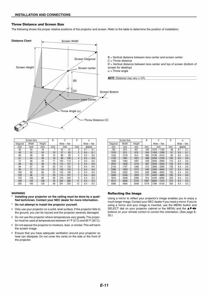
B = Vertical distance between lens center and screen centerC = Throw distanceD = Vertical distance between lens center and top of screen (bottom ofscreen for desktop)α = Throw angle
NOTE: Distances may vary +/-5%.
Throw Distance and Screen SizeThe following shows the proper relative positions of the projector and screen. Refer to the table to determine the position of installation.
Reflecting the ImageUsing a mirror to reflect your projector's image enables you to enjoy amuch larger image. Contact your NEC dealer if you need a mirror. If you'reusing a mirror and your image is inverted, use the MENU button andSELECT dial on your projector cabinet or the MENU and the ����buttons on your remote control to correct the orientation. (See page E-33.)
WARNING* Installing your projector on the ceiling must be done by a quali-
fied technician. Contact your NEC dealer for more information.
* Do not attempt to install the projector yourself.
• Only use your projector on a solid, level surface. If the projector falls tothe ground, you can be injured and the projector severely damaged.
• Do not use the projector where temperatures vary greatly. The projec-tor must be used at temperatures between 41˚F (5˚C) and 95˚F (35˚C).
• Do not expose the projector to moisture, dust, or smoke. This will harmthe screen image.
• Ensure that you have adequate ventilation around your projector soheat can dissipate. Do not cover the vents on the side or the front ofthe projector.
αWide – Tele
Screen Size B CWide – TeleDiagonal Width Height
degree9.7 - 8.79.5 - 8.79.5 - 8.69.5 - 8.69.4 - 8.69.4 - 8.69.4 - 8.69.4 - 8.69.4 - 8.69.4 - 8.69.4 - 8.59.4 - 8.59.4 - 8.5
D
mm4576109141021109712191280137215241829228627433048
mm1070 - 11901450 - 15902190 - 24102450 - 27002640 - 29002930 - 32303080 - 33903300 - 36403680 - 40504420 - 48605530 - 60906650 - 73107390 - 8130
mm183244366408439487512548609731914
10971219
mm762
101615241702182920322134228625403048381045725080
mm610813
12191361146316261707182920322438304836584064
mm466192
102110122128137153183229275305
αWide – Tele
Screen Size B CWide – TeleDiagonal Width Height
degree9.7 - 8.79.5 - 8.79.5 - 8.69.5 - 8.69.4 - 8.69.4 - 8.69.4 - 8.69.4 - 8.69.4 - 8.69.4 - 8.69.4 - 8.59.4 - 8.59.4 - 8.5
D
inch1824364043485054607290
108120
inch42 - 4757 - 6386 - 9596 - 106
104 - 114115 - 127121 - 133130 - 143145 - 159174 - 191218 - 240262 - 288291 - 320
inch7
101416171920222429364348
inch3040606772808490100120150180200
inch24324854586467728096
120144160
inch22444555679
1112

E-12
COMPUTERS-VIDEO INAUDIO IN
AC IN
VIDEO IN
COMPUTERAUDIO IN
PHONE
PHONE
Making Connections
NOTE: When using with a notebook PC, be sure to connect between the projector and the notebook PC before turning on the power to the notebook PC. In most casessignal cannot be output from RGB output unless the notebook PC is turned on after connecting with the projector.* If the screen goes blank while using your remote control, it may be the result of the computer's screen-saver or power management software.* If you accidentally hit the POWER button on the remote control, wait 60 seconds and then press the POWER button again to resume.
Connecting Your PC or Macintosh Computer
Audio cable (not supplied)
IBM VGA or Compatibles (Notebook type)or Macintosh (Notebook type)
IBM PC or Compatibles (Desktop type)or Macintosh (Desktop type)
RGB signal cable (supplied)To mini D-Sub 15-pin connector on the pro-jector. It is recommended that you use acommercially available distribution amplifierif connecting a signal cable longer than thesupplied one.
NOTE: For older Macintosh,use a commercially availablepin adapter (not supplied) toconnect to your Mac's videoport.
Connecting your PC or Macintosh computer to your projector will enable you to project your computer's screen image for an impressive presentation.To connect to a PC or Macintosh, simply:
1. Turn off the power to your projector and computer.
2. Use the supplied signal cable to connect your PC or Macintosh to the projector.
3. Turn on the projector and the computer.
4. If the projector goes blank after a period of inactivity, it may be caused by a screen saver installed on the computer you've connected to the projector.
INSTALLATION AND CONNECTIONS

E-13
INSTALLATION AND CONNECTIONS
To connect SCART output (RGB)Before connections: An exclusive SCART adapter (ADP-SC1) and a commercially available SCART cable are required for this connection.
NOTE: Audio signal is not available for this connection.
1. Turn off the power to the projector and your video equipment.
2. Use the NEC ADP-SC1 SCART adapter and a commercially availableSCART cable to connect the COMPUTER input of your projector anda SCART output (RGB) of your video equipment.
3. Turn on the power to the projector and your video equipment.
4. Use the COMPUTER button on the remote control to select the COM-PUTER input.
Video equipment such as DVD player
Projector
ADP-SC1Commercially availableSCART cable
Female
To COMPUTER connector
COMPUTERS-VIDEO INAUDIO IN
AC IN
VIDEO IN
COMPUTER
Using the projector in portrait modeWhen connecting with a Tablet PC, you can display an image in portraitmode with the projector on its side.• Place the projector on a location such as a table with the terminal
panel side up.
• Be sure to place the projector on a flat level surface.
• Auto Keystone correction feature is not available.
• The on-screen menu will not be rotated.
ZOOM
FOCUS
PUSH
LAMP
MEN
U
SOURCEEN
TERSTATU
S
POW
ER
ON
/STAND
BY
SELECT
COMPUTER
S-VIDEO IN
AUDIO IN
VIDEO IN
5. Press the MENU button on the remote control to display the menu.
6. From the menu, select [To Advanced Menu] → [Setup 2] → [SignalSelect Computer] → [Scart].SCART is a standard European audio-visual connector for TVs, VCRsand DVD players. It is also referred to as Euro-connector.
NOTE: The ADP-SC1 SCART adapter is obtainable from your NEC dealer in Eu-rope. Contact your NEC dealer in Europe for more information.
The projected image is displayed at a lower level thanthe normal position. Adjust the projection angle andposition for the correct position of the projected imageon screen.
• If the image is displayed upside down, select [Advanced menu] →[Setup 1] → [Portrait] → [0°] or [180°] for display orientation of yourPC. See also page E-33 for Portrait.

E-14
AUDIO INL R AUDIO OUT
L R
Component
Y Cb Cr
COMPUTERS-VIDEO INAUDIO IN
AC IN
VIDEO IN
COMPUTERAUDIO IN
INSTALLATION AND CONNECTIONS
Connecting Your DVD Player
DVD player
You can connect your projector to a DVD player with component output or Video output. To do so, simply:
1. Turn off the power to your projector and DVD player.
2. If your DVD player has the component video (Y,Cb,Cr) output, use a commercially available component video cable (RCA�3) and the optional 15-pin-to-RCA (female)�3 cable to connect your DVD player to the COMPUTER input connector on the projector.
For a DVD player without component video (Y,Cb,Cr) output, use common RCA cables (not provided) to connect a composite VIDEO output of theDVD player to the Video Input of the projector.
3. Turn on the projector and DVD player.
NOTE: Refer to your DVD player's owner's manual for more information about your DVD player's video output requirements.
Component video RCA�3 cable(not supplied)
Optional 15-pin-to-RCA(female)�3 cable (ADP-CV1)
Audio cable(not supplied)
Audio Equipment

E-15
AUDIO INL RAUDIO OUT
L R
VIDEO OUTS-VIDEO VIDEO
COMPUTERS-VIDEO INAUDIO IN
AC IN
VIDEO IN
S-VIDEO IN VIDEO IN
INSTALLATION AND CONNECTIONS
VCR/ Laser disc player
Connecting Your VCR or Laser Disc Player
Audio equipment
S-Video cable (not supplied)Video cable (not supplied)
Audio cable (not supplied)
Use common RCA cables (not provided) to connect your VCR, laser disc player or document camera to your projector.To make these connections, simply:
1. Turn off the power to the projector and VCR, laser disc player or document camera.
2. Connect one end of your RCA cable to the video output connector on the back of your VCR or laser disc player, connect the other end to the Videoinput on your projector. Use an audio cable (not supplied) to connect the audio from your VCR or laser disc player to your audio equipment (if yourVCR or laser disc player has this capability). Be careful to keep your right and left channel connections correct for stereo sound.
3. Turn on the projector and the VCR or laser disc player.
NOTE: Refer to your VCR or laser disc player owner's manual for more information about your equipment's video output requirements.

E-16
INSTALLATION AND CONNECTIONS
ZOOM
FOCUS
LAMPMENU
SOURCE ENTER
STATUS POWER
ON/STAND BY
SELECT
COMPUTER
S-VIDEO IN
AUDIO IN
VIDEO IN
PUSH
CLOSE
Attaching the Projector to a Tripod
The projector can be used with a camera tripod.To attach the projector to a tripod, use the supplied tripod adapter.
CAUTIONCare should be taken in handling a tripod.Using the tripod on an unstable surface may result in thetripod falling over or the projector falling which may resultin damage to the projector and possible personal injury.Read the instructions supplied with your tripod for handlingand cautions.• Use a tripod that can fully support the weight of the pro-
jector (approximately 5.5 lb/2.5 kg including attachment).• Place the tripod with its feet fully open and weight evenly
distributed for stability.• When using a tripod with a geared elevator, do not ex-
tend the geared elevator.• When displaying an image in portrait mode (with the
projector on its side) (page E-13), be sure the tripod isbalanced for stability. Failure to do so may result in thetripod falling over.
Preparation:1. Disconnect all the cables.2. A flat-blade screwdriver is required for attaching the sup-
plied three (3) screws. Use the supplied flat-blade screw-driver.
1. Turn the projector upside down.Place the projector on a soft cloth so as not to scratch the cabinetsurface.
2. Attach the supplied tripod adapter to the bottom of theprojector.Secure the tripod adapter to the projector with the supplied (3) screws.
3. Attach the projector to the tripod.Open the tripod to a fully extended position for greatest stability.
4. Connect all the cables.

E-17
Connecting the Supplied Power CableConnect the supplied power cable to the projector.First connect the supplied power cable's two-pin plug to the AC IN of theprojector, and then connect the other plug of the supplied power cable inthe wall outlet.
INSTALLATION AND CONNECTIONS
ZOOM
FOCUS
LAMPMENU
SOURCE ENTER
STATUS POWER
ON/STAND BY
SELECT
COMPUTER
S-VIDEO IN
AUDIO IN
VIDEO IN
PUSH
LAMP
MENU
STATUS
ON/STAND BY
POWERPOWERPOWER
The projector will go into its standby mode and the power indicator willglow orange.
LAMP
MENU
SOURCEENTER
STATUS
ON/STAND BY
SELECT
POWERPOWERPOWER
CAUTION:Do not unplug the power cable from the wall outlet under any one of thefollowing circumstances.Doing so can cause damage to the projector:* While the Hour Glass icon appears.
* While the cooling fans are running. (The cooling fans continue to workfor 60 seconds after the projector is turned off).
E-18
PROJECTING AN IMAGE (BASIC OPERATION)
This section describes how to turn on the projector and to project a pic-ture onto the screen.
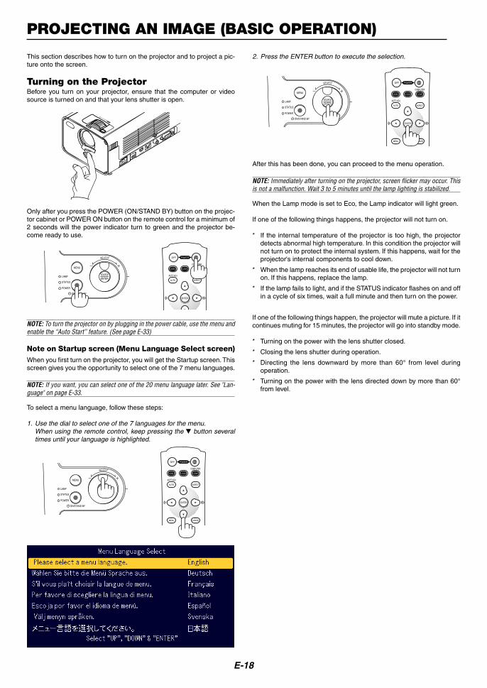
Turning on the ProjectorBefore you turn on your projector, ensure that the computer or videosource is turned on and that your lens shutter is open.
ZOOM
FOCUS
COMPUTER
S-VIDEO IN
AUDIO IN
VIDEO IN
PUSH
CLOSE
Only after you press the POWER (ON/STAND BY) button on the projec-tor cabinet or POWER ON button on the remote control for a minimum of2 seconds will the power indicator turn to green and the projector be-come ready to use.
LAMP
STATUS
POWER
ON/STAND BY
SELECT
MENU
SOURCEENTER
OFF
COMPUTER
AUTO ADJ.
P0WER ON
VIDEO
AUTO ASPECT
COMP.S-VIDEO
ENTER
NOTE: To turn the projector on by plugging in the power cable, use the menu andenable the “Auto Start” feature. (See page E-33)
Note on Startup screen (Menu Language Select screen)When you first turn on the projector, you will get the Startup screen. Thisscreen gives you the opportunity to select one of the 7 menu languages.
NOTE: If you want, you can select one of the 20 menu language later. See "Lan-guage" on page E-33.
To select a menu language, follow these steps:
1. Use the dial to select one of the 7 languages for the menu.When using the remote control, keep pressing the � button severaltimes until your language is highlighted.
LAMP
STATUS
POWER
ON/STAND BY
SELECT
MENU
SOURCEENTER
OFF
COMPUTER
AUTO ADJ.
P0WER ON
VIDEO
AUTO
MENU CANCEL
ASPECT
COMP.S-VIDEO
ENTER
2. Press the ENTER button to execute the selection.
LAMP
STATUS
POWER
ON/STAND BY
SELECT
MENU
SOURCEENTER
OFF
COMPUTER
AUTO ADJ.
P0WER ON
VIDEO
AUTO
MENU CANCEL
ASPECT
COMP.S-VIDEO
ENTER
After this has been done, you can proceed to the menu operation.
NOTE: Immediately after turning on the projector, screen flicker may occur. Thisis not a malfunction. Wait 3 to 5 minutes until the lamp lighting is stabilized.
When the Lamp mode is set to Eco, the Lamp indicator will light green.
If one of the following things happens, the projector will not turn on.
* If the internal temperature of the projector is too high, the projectordetects abnormal high temperature. In this condition the projector willnot turn on to protect the internal system. If this happens, wait for theprojector's internal components to cool down.
* When the lamp reaches its end of usable life, the projector will not turnon. If this happens, replace the lamp.
* If the lamp fails to light, and if the STATUS indicator flashes on and offin a cycle of six times, wait a full minute and then turn on the power.
If one of the following things happen, the projector will mute a picture. If itcontinues muting for 15 minutes, the projector will go into standby mode.
* Turning on the power with the lens shutter closed.
* Closing the lens shutter during operation.
* Directing the lens downward by more than 60° from level duringoperation.
* Turning on the power with the lens directed down by more than 60°from level.

E-19
Selecting a Source
Selecting the computer or video source
Press any one of the COMPUTER, VIDEO orS-VIDEO buttons.
Press and quickly release the SOURCE button on the projector cabinetto display the Source list. Each time the SOURCE button is pressed,each source name will be highlighted in sequence. Highlighting a sourcename will display an hour glass icon in one second. After that the inputsignal will be selected.
PROJECTING AN IMAGE (BASIC OPERATION)
OFF
COMPUTER
AUTO ADJ.
PC-MUTE MAGNIFY
P0WER ON
VIDEO
AUTO
MENU
HELP
MUTE
PICTURE
FREEZE
CANCEL
ASPECT
COMP.S-VIDEO
ENTER
Adjustable Tilt Foot ButtonAdjustable Tilt Foot
NOTE: You can rotate the Fine Adjustment rings of both tilt feet on the left andright sides of the cabinet front for fine adjustment of the tilt feet.
Adjusting the Picture Size and PositionPlace your projector on a flat level surface and ensure that the projectoris square to the screen.
Lift the front edge of the projector to center the image vertically.* If the projected image does not appear square to the screen then use
the Keystone feature for proper adjustment. See page E-20.
Move the projector left to center the image horizontally on the screen.
Adjust the Tilt Foot1. Lift the front part of the projector.
Push and hold the PUSH symbol of the Adjustable Tilt Foot button onthe front top of the projector to extend the adjustable tilt feet up to amaximum height.
ZOOM
FOCUS
LAMPMENU
SOURCE ENTER
STATUS POWER
ON/STAND BY
SELECT
COMPUTER
S-VIDEO IN
AUDIO IN
VIDEO IN
PUSH
CLOSE
1
3
2
ZOOM
FOCUS
LAMPMENU
SOURCE ENTER
STATUS POWER
ON/STAND BY
SELECT
COMPUTER
S-VIDEO IN
AUDIO IN
VIDEO IN
PUSH
CLOSE
4
Using the cabinet buttons
NOTE: If no input signal is available, the projector will display a blue background(factory preset).
LAMP
STATUS
POWER
ON/STAND BY
SELECT
MENU
SOURCEENTER
Using the Remote Control
2. Lower the front of the projector to the desired height (max. 40mm/1.6”)and release the Adjustable Tilt Foot Button to lock the Adjustable tiltfoot. There is approximately 10 degrees of up and down adjustmentfor the front of the projector.
CAUTION:Do not use the tilt-foot for purposes other than originally intended.Misuses such as gripping the tilt-foot or hanging on the wall cancause damage to the projector.

E-20
You can use the ZOOM ring to enlarge or reduce an image size.
FocusUse the FOCUS ring to obtain the best focus.
Correcting the Vertical Keystone Distortion
Auto Keystone CorrectionThe Auto Keystone correction feature will correct the vertical distortion ofa projected image on the screen. No special operation required. Just putthe projector on a flat surface.Note that the vertical keystone angle can be corrected between 30 de-grees upward and 30 degrees downward of projector tilt from level.
NOTE: Keystone correction angle could be less than 30 degrees for some signalsthat have a high resolution or frequency such as UXGA.
Manual Keystone CorrectionYou can also correct the vertical keystone distortion manually.To do so:1. Press the MENU button.
The menu will be displayed.
PROJECTING AN IMAGE (BASIC OPERATION)
ZOOM
FOCUS
PUSH
ZOOM
FOCUS
PUSH
2. Select the Keystone function. Rotate the SELECT +/- dial to select“Keystone” and then press the ENTER button.
The three options will be displayed.
3. Rotate the SELECT +/- dial to select “Manual” and then press theENTER button.
The Keystone adjustment bar will be displayed.
4. Correct the vertical distortion.Rotate the SELECT +/– dial to correct the vertical keystone distor-tion.
5. Press the ENTER button to take effect.
6. Press the MENU button to close the menu.
NOTE:• You can save the changes by selecting “Manual (Save)” when you turn off the
projector.• When you use the projector in portrait mode, vertical keystone distortion
looks horizontal keystone distortion.
ZoomUse the ZOOM ring to finely adjust the image size on the screen.
E-21
PROJECTING AN IMAGE (BASIC OPERATION)
Optimizing RGB Picture Automatically
Adjusting the Image Using Auto AdjustOptimizing RGB image automatically.
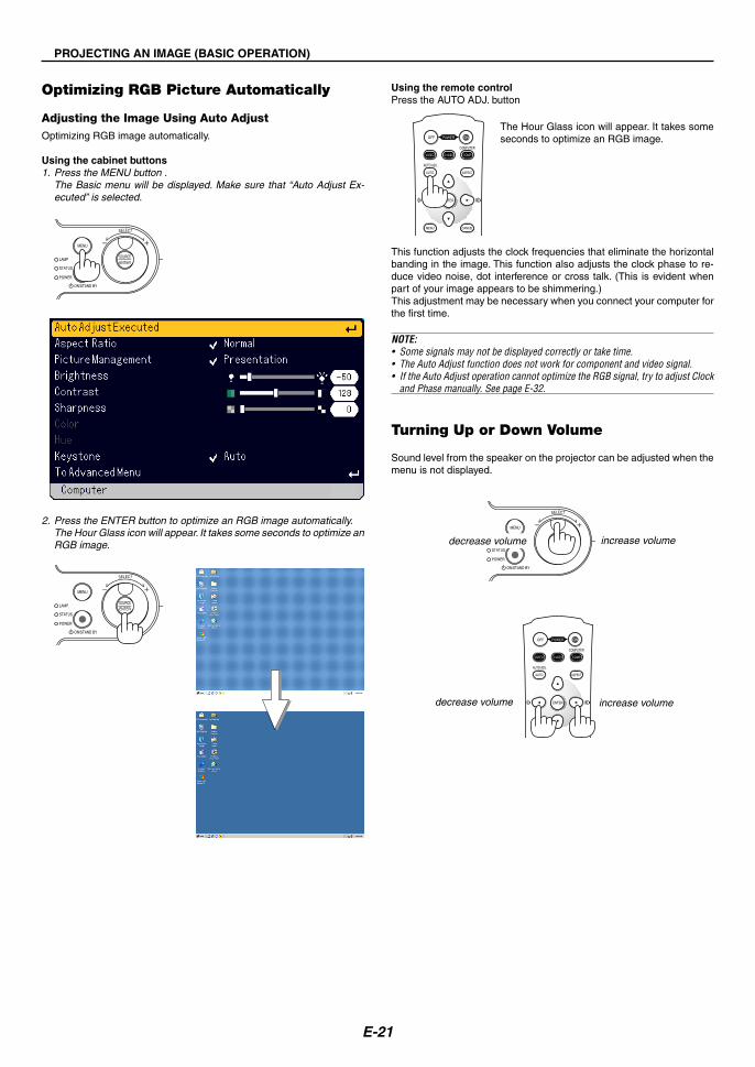
Using the cabinet buttons1. Press the MENU button .
The Basic menu will be displayed. Make sure that “Auto Adjust Ex-ecuted” is selected.
LAMP
STATUS
POWER
ON/STAND BY
SELECT
MENU
SOURCEENTER
OFF
COMPUTER
AUTO ADJ.
P0WER ON
VIDEO
AUTO
MENU CANCEL
ASPECT
COMP.S-VIDEO
ENTER
LAMP
STATUS
POWER
ON/STAND BY
SELECT
MENU
SOURCEENTER
2. Press the ENTER button to optimize an RGB image automatically.The Hour Glass icon will appear. It takes some seconds to optimize anRGB image.
Using the remote controlPress the AUTO ADJ. button
The Hour Glass icon will appear. It takes someseconds to optimize an RGB image.
This function adjusts the clock frequencies that eliminate the horizontalbanding in the image. This function also adjusts the clock phase to re-duce video noise, dot interference or cross talk. (This is evident whenpart of your image appears to be shimmering.)This adjustment may be necessary when you connect your computer forthe first time.
NOTE:• Some signals may not be displayed correctly or take time.• The Auto Adjust function does not work for component and video signal.• If the Auto Adjust operation cannot optimize the RGB signal, try to adjust Clock
and Phase manually. See page E-32.
Turning Up or Down Volume
Sound level from the speaker on the projector can be adjusted when themenu is not displayed.
increase volumedecrease volume
OFF
COMPUTER
AUTO ADJ.
P0WER ON
VIDEO
AUTO
MENU CANCEL
ASPECT
COMP.S-VIDEO
ENTER
LAMP
STATUS
POWER
ON/STAND BY
SELECT
MENU
SOURCEENTER increase volumedecrease volume

E-22
Turning off the Projector
To turn off the projector:First, press the POWER (ON/STAND BY) button on the projector cabinetor the POWER OFF button on the remote control. The “Power Off / Areyou sure?” message will appear.
Secondly, press the ENTER button or press the POWER (ON/STANDBY) or the POWER OFF button again.The power indicator will glow orange. After the projector turns off, thecooling fans keep operating for 60 seconds (Cooling-off time).Lastly unplug the power cable. The power indicator will go out.
CAUTIONDo not unplug the power cable from the wall outlet under any one ofthe following circumstances. Doing so can cause damage to theprojector:• While the Hour Glass icon appears.
• While the cooling fans are running. (The cooling fans continue towork for 60 seconds after the projector is turned off).
OFF
COMPUTER
AUTO ADJ.
P0WER ON
VIDEO
AUTO
MENU CANCEL
ASPECT
COMP.S-VIDEO
ENTER
LAMP
STATUS
POWER
ON/STAND BY
SELECT
MENU
SOURCEENTER
PROJECTING AN IMAGE (BASIC OPERATION)
After Use
Preparation: Make sure that the projector is not turned on.
1. Unplug the power cable.
2. Disconnect any other cables.
3. Retract adjustable tilt feet if extended.
ZOOM
FOCUS
LAMPMENU
SOURCE ENTER
STATUS POWER
ON/STAND BY
SELECT
COMPUTE
S-VIDEO IN
AUDIO IN
VIDEO IN
PUSH
CLOSE
3
1
2
� Lift the front part of the projector.
� Push and hold the PUSH symbol of the Adjustable Tilt Foot button toextend the adjustable tilt feet up to a maximum height.
� Lower the front of the projector while pressing and holding theAdjustable Tilt Foot button until retracting the Adjustable Tilt Footdown to a minimum height.
4. Use the Lens Shutter lever to close the lens shutter.
ZOOM
FOCUS
MENU
SOURCE ENTER
SELECT
S-VIDEO IN
AUDIO IN
VI
PUSH
5. Put the projector and its accessories in the soft carrying case. See “Using the Soft Carrying Case” on the following page.

E-23
Using the Soft Carrying CaseThe accessory pouch can be attached to the soft carrying case as shown in the drawing.
* Placing the projector and its accessories in the soft carrying case
PROJECTING AN IMAGE (BASIC OPERATION)
Put through and fix it
Work should be done on a flat level surface to prevent overturning.
Put through
ZOOM
FOCUS
PUSHPUSH
LAMP MENU
SOURCEENTER
STATUSPOWERON/STAND BY
SELECT
OFF
COMPUTER
AUTO ADJ.
PC-MUTEMAGNIFY
P0WER
VIDEO
AUTO
ASPECT
COMP.
S-VIDEO
ENTERMENU
HELP
MUTE
PICTURE
CANCELFREEZE
ON
Remote control
Power cable
Projector
RGB signal cable
Quick Guide
* The length of the belt is adjustable.
Remove

E-24
CONVENIENT FEATURES
Turning Off the Image and Sound
Press the PIC-MUTE button to turn off the image and sound for a shortperiod of time. Press again to restore the image and sound.
Freezing a Picture
Press the FREEZE button to freeze a picture. Press again to resumemotion.
Enlarging and Moving a Picture
You can enlarge the picture up to 400 percent.To do so:
1. Press the MAGNIFY (+) button to magnify the picture.To move the magnified image, use the ���� button.
Getting the Information
You get the information about the signal and projector settings.
Display Information Exit Information
2. Press the MAGNIFY (-) button to return the image to the original size.
PC-MUTE MAGNIFY
MENU
HELP
MUTE
PICTURE
FREEZE
CANCEL
PC-MUTE MAGNIFY
MENU
HELP
MUTE
PICTURE
FREEZE
CANCEL
PC-MUTE MAGNIFY
MENU
HELP
MUTE
PICTURE
FREEZE
CANCEL
PC-MUTE MAGNIFY
MENU
HELP
MUTE
PICTURE
FREEZE
CANCEL
OFF
COMPUTER
AUTO ADJ.
P0WER ON
VIDEO
AUTO
MENU CANCEL
ASPECT
COMP.S-VIDEO
ENTER
Security
A keyword can be set for your projector to avoid operation by an unau-thorized user using the Menu. When a keyword is set, turning on theprojector will display the Keyword input screen. Unless the correct key-word is entered, the projector cannot project an image.
To set a keyword:
1. Press the MENU button.The Basic menu will be displayed.
2. Rotate the SELECT +/- dial to select [To Advanced Menu] and pressthe ENTER button.The Advanced menu will be displayed.
PC-MUTE MAGNIFY
MENU
HELP
MUTE
PICTURE
FREEZE
CANCEL
PC-MUTE MAGNIFY
MENU
HELP
MUTE
PICTURE
FREEZE
CANCEL
E-25
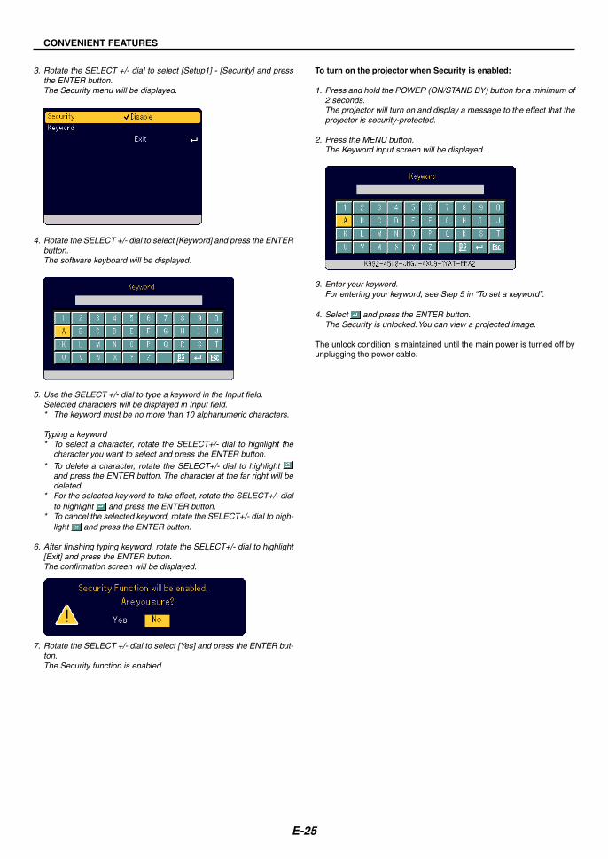
3. Rotate the SELECT +/- dial to select [Setup1] - [Security] and pressthe ENTER button.The Security menu will be displayed.
4. Rotate the SELECT +/- dial to select [Keyword] and press the ENTERbutton.The software keyboard will be displayed.
5. Use the SELECT +/- dial to type a keyword in the Input field.Selected characters will be displayed in Input field.* The keyword must be no more than 10 alphanumeric characters.
Typing a keyword* To select a character, rotate the SELECT+/- dial to highlight the
character you want to select and press the ENTER button.* To delete a character, rotate the SELECT+/- dial to highlight
and press the ENTER button. The character at the far right will bedeleted.
* For the selected keyword to take effect, rotate the SELECT+/- dialto highlight and press the ENTER button.
* To cancel the selected keyword, rotate the SELECT+/- dial to high-light and press the ENTER button.
6. After finishing typing keyword, rotate the SELECT+/- dial to highlight[Exit] and press the ENTER button.The confirmation screen will be displayed.
7. Rotate the SELECT +/- dial to select [Yes] and press the ENTER but-ton.The Security function is enabled.
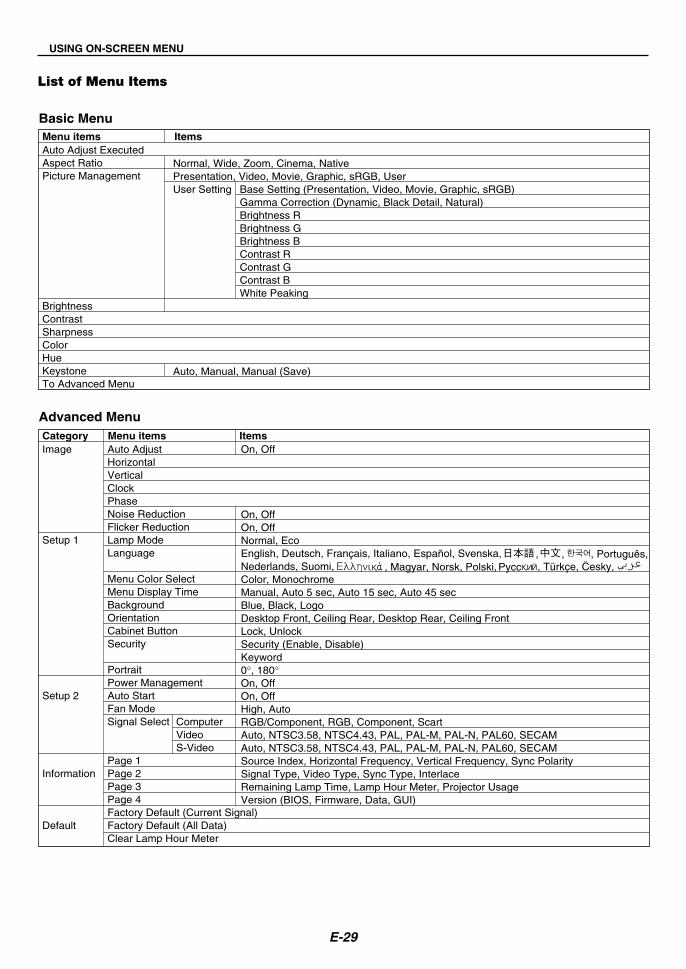
To turn on the projector when Security is enabled:
1. Press and hold the POWER (ON/STAND BY) button for a minimum of2 seconds.The projector will turn on and display a message to the effect that theprojector is security-protected.
2. Press the MENU button.The Keyword input screen will be displayed.
3. Enter your keyword.For entering your keyword, see Step 5 in “To set a keyword”.
4. Select and press the ENTER button.The Security is unlocked. You can view a projected image.
The unlock condition is maintained until the main power is turned off byunplugging the power cable.
CONVENIENT FEATURES

E-26
CONVENIENT FEATURES
To disable the Security function:
1. Press the MENU button.The Basic menu will be displayed.
2. Rotate the SELECT +/- dial to select [To Advanced Menu] and pressthe ENTER button.The Advanced menu will be displayed.
3. Rotate the SELECT +/- dial to select [Setup1] - [Security] and pressthe ENTER button.The Keyword input screen will be displayed.
4. Enter your keyword.For entering your keyword, see Step 5 in “To set a keyword”.
5. Rotate the SELECT +/– dial to select and press the ENTER but-ton.The Security is unlocked. The Security menu will be displayed.
6. Rotate the SELECT +/- dial to select [Security] and press the ENTERbutton.
7. Rotate the SELECT +/- dial to select [Disable] and press the ENTERbutton.This will disable the Security function and return to the Security menu.
8. Rotate the SELECT +/- dial to select [Exit] and press the ENTER.
9. Press the MENU button to close the menu.
NOTE:If you forget your keyword, contact your dealer. Your dealer will provide youwith your keyword in exchange for your request code. Your request code isdisplayed in the Keyword input screen. In this example “K992-45L8-JNGJ-4XU9-1YAT-EEA2” is a request code.

E-27
USING ON-SCREEN MENU
Basic Menu OperationThe Menu consists of Basic and Advanced. While the Basic menu con-tains minimum essentials of menus and commands, the Advanced menucontains all the available menus and commands.
The Basic menu is accessed by pressing the MENU button.Selecting “To Advanced Menu” in Basic menu will go to the Advancedmenu.
Using the MenusFor Basic menu
1. Press the MENU button to display the Basic menu.
2. Rotate the SELECT +/- dial to highlight the menu item you want toadjust or set.The example below is for Picture Management.
3. Press the ENTER button.The Picture Management item will be displayed on its right side.
4. Rotate the SELECT +/- dial to highlight the item you want to adjust orset.The example below is for Graphic.
5. Press the ENTER button.The item is selected. This will return to the Basic menu.
6. Press the MENU button to close the menu.
NOTE:* The menu will automatically disappear if no operation is made for 45 seconds.* The menu display time (default 45 seconds) can be changed. See page E-33.* The on-screen menu may not be displayed correctly while interlaced motion
video image is projected.
For Advanced menu
1. Press the MENU button to display the Basic menu.
2. Rotate the SELECT +/- dial to highlight [To Advanced menu] and pressthe ENTER button.The Advanced menu will be displayed.

E-28
3. Rotate the SELECT +/- dial clockwise.Keep rotating the SELECT +/- dial until the highlight reaches [NoiseReduction]. When the highlight reaches [Flicker Reduction], [Setup 1]menu will be displayed.
Keep rotating the SELECT +/- dial clockwise and the menu items willsequence as follows: [Image] → [Setup 1] → [Setup 2] → [Information] →[Default] → [Image] → ...
Keep rotating the SELECT +/- dial counterclockwise and the menu itemswill sequence as follows: [Default] → [Information] → [Setup 2] → [Setup1] → [Image] → [Default] → ...
Adjusting and Setting ItemsFor Adjusting items
1. Rotate the SELECT +/- dial to highlight the menu item you want toadjust.
2. Press the ENTER button.
3. Rotate the SELECT +/- dial to adjust the item.
4. Press the ENTER button. Changes will take effect.
For Selecting items
1. Rotate the SELECT +/- dial to highlight the menu item you want to set.
USING ON-SCREEN MENU
2. Press the ENTER button.The selected item will be displayed.
3. Rotate the SELECT +/- dial to highlight the item you want to set.
4. Press the ENTER button.This will return to the previous menu.
NOTE:The ENTER/SOURCE button on the cabinet works as:* Execute menu selection.* Adjust the slide bar.* Display the submenu
E-29
List of Menu Items
USING ON-SCREEN MENU
Basic Menu
Advanced Menu
Menu items ItemsAuto Adjust ExecutedAspect RatioPicture Management
BrightnessContrastSharpnessColorHueKeystoneTo Advanced Menu
Normal, Wide, Zoom, Cinema, NativePresentation, Video, Movie, Graphic, sRGB, UserUser Setting
Auto, Manual, Manual (Save)
Base Setting (Presentation, Video, Movie, Graphic, sRGB)Gamma Correction (Dynamic, Black Detail, Natural)Brightness RBrightness GBrightness BContrast RContrast GContrast BWhite Peaking
Category Menu items ItemsImage
Setup 1
Setup 2
Information
Default
Auto AdjustHorizontalVerticalClockPhaseNoise ReductionFlicker ReductionLamp ModeLanguage
Menu Color SelectMenu Display TimeBackgroundOrientationCabinet ButtonSecurity
PortraitPower ManagementAuto StartFan ModeSignal Select
Page 1Page 2Page 3Page 4Factory Default (Current Signal)Factory Default (All Data)Clear Lamp Hour Meter
On, Off
On, OffOn, OffNormal, EcoEnglish, Deutsch, Français, Italiano, Español, Svenska,Nederlands, Suomi, Color, MonochromeManual, Auto 5 sec, Auto 15 sec, Auto 45 secBlue, Black, LogoDesktop Front, Ceiling Rear, Desktop Rear, Ceiling FrontLock, UnlockSecurity (Enable, Disable)Keyword0°, 180°On, OffOn, OffHigh, AutoRGB/Component, RGB, Component, ScartAuto, NTSC3.58, NTSC4.43, PAL, PAL-M, PAL-N, PAL60, SECAMAuto, NTSC3.58, NTSC4.43, PAL, PAL-M, PAL-N, PAL60, SECAMSource Index, Horizontal Frequency, Vertical Frequency, Sync PolaritySignal Type, Video Type, Sync Type, InterlaceRemaining Lamp Time, Lamp Hour Meter, Projector UsageVersion (BIOS, Firmware, Data, GUI)
, ,, Türkçe, Cesky, , Magyar, Norsk, Polski,
, Português,
ComputerVideoS-Video

E-30
Menu windows or dialog boxes typically have the following elements:
Title ........................... Indicates the menu title.
Highlight .................... Indicates the selected menu or item.
Source ....................... Indicates the currently selected source.
Return key symbol .... Indicates further choices are available.
Radio button .............. Use this round button to select an option in a dialog box.
Check mark ............... Indicates the item is selected.
Slide bar .................... Indicates settings or the direction of adjustment.
Key symbol ................ Indicates the Cabinet Button is locked.
Thermometer symbol .......... Indicates the lamp mode is forcibly set to Eco mode because the internal temperature is too high.
Menu Elements
Slide barHighlight
Radio button
Source Key symbol
Thermometer symbol
USING ON-SCREEN MENU
Check mark
<Basic menu>
Title
<Advanced menu>
Return key symbol

E-31
USING ON-SCREEN MENU
Menu Descriptions & Functions
Basic Menu
[Auto Adjust Executed]Optimizing RGB image automatically. (See page E-21)
Selecting Aspect Ratio [Aspect Ratio]
Aspect Ratio allows you to select the best Aspect mode to display yoursource image. You can also display the Aspect Ratio window by pressingthe “ASPECT” button on the remote control. (See page E-8).
Normal Wide Zoom Cinema Native
Standard4:3 Aspect
Left and rightstretched
Left and rightstretched
When 16:9 is selected from the source (i.e. DVD player), the follow-ing selections will display:
Normal Wide Zoom Cinema Native
16:9 imagedisplayed in4:3 mode
Left and rightstretched
Left and rightstretched to
display the trueaspect
When 4:3 is selected from the source (i.e. DVD player), the followingselections will display:
Native (COMPUTER only): Turns off the Advanced AccuBlend fea-ture. The projector displays the current image in its true resolution.
NOTE:* While you are displaying an image with higher resolution than the projector’s
native resolution, “Native” is not available.* Selecting “Cinema” will display the Cinema Position slide bar which allows
you to adjust the vertical position of the image on the screen.
CopyrightPlease note that using this projector for the purpose of commercial gain or theattraction of public attention in a venue such as a coffee shop or hotel andemploying compression or expansion of the screen image with a "Aspect Ra-tio" setting may raise concern about the infringement of copyrights which areprotected by copyright law.
[Picture Management]
This option allows you to adjust neutral tint for yellow, cyan or magenta.There are 5 factory presets optimized for various types of images, or youcan set user adjustable settings.
Presentation .. Recommended for making a presentation using aPowerPoint file
Video ............. Recommended for regular picture such as TV program
Movie ............. Recommended for movie
Graphic .......... Recommended for graphics
sRGB ............. Standard color values
User ............... User adjustable
NOTE: When “sRGB”, “Graphic”, “Video” or “Movie” is selected, the bright-ness decreases slightly when compared to “Presentation”. This is not a mal-function.
User Setting (when using User)When selecting a user adjustable preset (User Setting), the submenuwill be displayed.You can customize each gamma or color. To do so, first select “UserSetting” and press the ENTER button, and then proceed with the fol-lowing steps.
Selecting Base Setting [Base setting]This feature allows you to use white balance or gamma values asreference data to optimize for various types of images. You can selectone of the following five settings.• Presentation• Video• Movie• Graphic• sRGB
Selecting Gamma Correction Mode [Gamma Correction]Each mode is recommended for :Dynamic ......... For true color reproduction of natural tones
Natural ........... Normal settings
Black Detail .... For dark portions of a picture

E-32
USING ON-SCREEN MENU
Advanced Menu
[Image]
Enabling Auto Adjust [Auto Adjust]When “Auto Adjust” is set to “On”, the projector automatically determinesthe best resolution for the current RGB input signal to project an imageusing NEC’s Advanced AccuBlend Intelligent Pixel Blending Technology.The image can be automatically adjusted for position and stability;“Horizontal Position”, “Vertical Position”, “Clock” and “Phase”.
On .................. Automatically adjusts image “Horizontal Position”, “Ver-tical Position”, “Clock” and “Phase”.
Off .................. User can adjust the image display functions (“Horizon-tal Position”, “Vertical Position”, “Clock” and “Phase”)manually.
Adjusting Position/Clock (when Auto Adjust is off)
This allows you to manually adjust the image horizontally and vertically,and adjust Clock and Phase.
[Horizontal/Vertical]Adjusts the image location horizontally and vertically.This adjustment is made automatically when the Auto Adjust is turnedon.
[Clock]Use this item with the “Auto Adjust off” to fine tune the computer im-age or to remove any vertical banding that might appear. This functionadjusts the clock frequencies that eliminate the horizontal banding inthe image. This adjustment may be necessary when you connect yourcomputer for the first time. This adjustment is made automatically whenthe Auto Adjust is turned on.
[Phase]Use this item to adjust the clock phase or to reduce video noise, dotinterference or cross talk. (This is evident when part of your imageappears to be shimmering.)Use “Phase” only after the “Clock” is complete.This adjustment is made automatically when the Auto Adjust is turnedon.
Turning On Noise Reduction [Noise Reduction]Reduces video noise.
NOTE: The lower the Noise Reduction level, the better the image quality by wayof higher video bandwidth.
Turning On Flicker Reduction [Flicker Reduction]Reduces flicker which can occur in an interlaced signal.
NOTE: When the Flicker Reduction is ON, jagged lines can be visible dependingon the signal. In that case, select OFF.
Adjusting White Balance [Brightness R/G/B, Contrast R/G/B]This allows you to adjust the white balance. Brightness for each color(RGB) is used to adjust the black level of the screen; Contrast for eachcolor (RGB) to adjust the white level of the screen.
Selecting White Peaking [White Peaking]Adjust the brightness of the white areas. As the picture becomes dim,it looks more natural.
NOTE: The White Peaking option is not available when “Presentation” is selectedin “Base Setting”.
[Brightness]Adjusts the brightness level or the back raster intensity.
[Contrast]Adjusts the intensity of the image according to the incoming signal.
[Sharpness]Controls the detail of the image for Video.
[Color]Increases or decreases the color saturation level (not valid for RGB).
[Hue]Varies the color level from +/- green to +/-blue. The red level is used asreference. This adjustment is only valid for Video and Component inputs(not valid for RGB).
NOTE: Some Picture items cannot be available depending on the input signal.
Input signal Brightness Contrast Sharpness Color HueRGB
Yes Yes Yes No No(Computer)Component
Yes Yes Yes Yes*1 No(Computer)Video and S-Video Yes Yes Yes Yes Yes*2
Yes: Available No: Not available
*1 Available on DVD (15 kHz), but not available on HDTV, 525p (480p)and 750p (720p).
*2 Available on NTSC only.
Correcting Vertical Keystone Distortion [Keystone]Corrects vertical keystone distortion.
Auto ............... Corrects vertical keystone distortion automatically. Seepage E-20.
Manual ........... Allows you to manually correct vertical keystone dis-tortion.
Manual (Save) This option enables you to save your current keystonecorrection settings. The settings are saved when youturn off the projector.
When you select “Manual” or “Manual (Save)“, you can correct keystonedistortion using the Keystone slide bar.

E-33
USING ON-SCREEN MENU
[Setup1]
Selecting Lamp Mode [Lamp Mode]This feature enables you to select two brightness modes of the lamp:Normal and Eco modes. The lamp life can be extended by using theEco mode.Normal Mode ... This is the default setting (100% Brightness).
Eco Mode ...... Select this mode to increase the lamp life (80% Bright-ness).
NOTE: Thermometer symbol indicates the lamp mode is forcibly set to Ecomode because the internal temperature is too high.
Selecting Menu Language [Language]You can choose one of 20 languages for on-screen instructions.
Selecting Menu Color [Menu Color Select]You can choose between two color modes for menu color: color andmonochrome.
Selecting Menu Display Time [Menu Display Time]This option allows you to select how long the projector waits after thelast touch of a button to turn off the menu.The preset choices are “Manual”, “Auto 5 sec”, “Auto 15 sec”, and“Auto 45 sec”. The “Auto 45 sec” is the factory preset.
Selecting a Color or Logo for Background [Background]Use this feature to display a black/ blue screen or logo when no signalis available.
Selecting Projector Orientation [Orientation]This sets the orientation of the image for your type of application. Theoptions are:desktop front projection, ceiling rear projection, desktop rear projec-tion, and ceiling front projection.
Disabling the Cabinet Buttons [Cabinet Button]This option turns on or off the Cabinet Button Lock function.
NOTE:* This Cabinet Button Lock does not affect the remote control functions.* When the cabinet buttons are locked, pressing and holding the MENU button
for about 10 seconds will change the setting to unlock.* Key symbol indicates the Cabinet Button is locked.
Enabling Security function [Security]This option allows you to prevent the projector from being used byunauthorized individuals.See page E-24 for details.
Selecting Display Orientation [Portrait]This allows you to select the projector's display orientation when youdisplay an image in portrait mode with the projector on its side. Seepage E-13. You can rotate the projected image 0° or 180° clockwisedepending on your PC.The default setting is 180°.
[Setup2]
Enabling Power Management [Power Management]When this option is on and there is no input for five minutes or more,the projector will automatically turn itself off.
Enabling Auto Start [Auto Start]Turns the projector on automatically when the power cable is insertedinto an active power outlet.This eliminates the need to always use the POWER (ON/STAND BY)button on the projector cabinet or the POWER OFF button on the re-mote control.
Enabling High Speed Fan Mode [Fan Mode]This option allows you to select two modes for fan speed: High modeand Auto mode.
High ............... The built-in fans run at a fixed high speed.
Auto ............... The built-in fans automatically run at a variable speedaccording to the internal temperature.
When you wish to cool down the temperature inside the projectorquickly, select “High”.
NOTE: Select High Speed Fan mode if you continue to use the projector forconsecutive days.
Selecting Signal Format [Signal Select]<Computer>Allows you to choose “RGB” for an RGB source such as a computer,or “Component” for a component video source such as a DVD player.Normally select “RGB/Component” and the projector automaticallydetects a component signal. However there may be some componentsignals that the projector is unable to detect. If this is the case, select“Component”. Select “Scart” for the European Scart.
<Video & S-Video>This feature enables you to select composite video standards manu-ally. Normally select “Auto”.When you select the video standard for Video and S-Video, select thevideo standard from the pull-down menu.This must be done for Video and S-Video respectively.

E-34
USING ON-SCREEN MENU
Displays the status of the current signal and lamp usage. This item hasfour pages. The information included is as follows:
Information Default
Returning to Factory Default [Factory Default]The Factory Default feature allows you to change adjustments and set-ting to the factory preset for source except the following:
<Current Signal>Resets the adjustments for the current signal to the factory preset levels.The items that can be reset are: Brightness, Contrast, Color, Hue, Sharp-ness, Aspect Ratio, Horizontal Position, Vertical Position, Clock, Phaseand Picture Management.
<All Data>Reset all the adjustments and settings for all the signals to the factorypreset.The items can be reset except Language, Security, Remaining LampTime, Lamp Hour Meter and Projector Usage. To reset the lamp usagetime, see “Clear Lamp Hour Meter” .
Clearing Lamp Hour Meter [Clear Lamp Hour Meter]Resets the lamp clock back to zero. Selecting this option displays submenufor a confirmation.
NOTE: The projector will turn off and go into standby mode after 1600 hours (upto 2100 hours in Eco mode) of service. If this happens, press the “HELP” buttonon the remote control for ten seconds to reset the lamp clock back to zero. Do thisonly after replacing the lamp.
* The progress indicator shows the percentage of remaining lamp life.The value informs you of the amount of lamp usage. When the remain-ing lamp time reaches 0, the Remaining Lamp Time bar indicatorchanges from 0% to 100 Hours and starts counting down.If the remaining lamp time reaches 0 hours, the projector will not turnon regardless of whether the lamp mode is set to Normal or Eco.
[Page 1]Source IndexHorizontal FrequencyVertical FrequencySync Polarity
[Page 2]Signal TypeVideo TypeSync TypeInterlace
[Page 3]Remaining Lamp Time (%)*Lamp Hour Meter (H)Projector Usage
[Page 4]Version (BIOS/Firmware/Data/GUI)

E-35
LAMP MENUSTATUSPOWERON/STAND BY
LAMP MENUSTATUSPOWERON/STAND BY
MAINTENANCE
This section describes the simple maintenance procedures you shouldfollow to replace the lamp and clean the filter.
Replacing the LampAfter your lamp has been operating for 1500 hours (up to 2000 hours inEco mode) or longer, the LAMP indicator in the cabinet will blink red andthe message will appear. Even though the lamp may still be working,replace it at 1500 (up to 2000 hours in Eco mode) hours to maintainoptimal projector performance.
CAUTION• DO NOT TOUCH THE LAMP immediately after it has been used. It
will be extremely hot. Turn the projector off, wait 60 seconds, andthen unplug the power cable. Allow at least one hour for the lampto cool before handling.
• DO NOT REMOVE ANY SCREWS except the lamp cover screwand the lamp case screw. You could receive an electric shock.
• The projector will turn off and go into stand by mode after 1600(up to 2100 hours in Eco mode) hours of service. If this happens,be sure to replace the lamp. If you continue to use the lamp after1500 hours (up to 2000 hours in Eco mode) of use, the lamp bulbmay shatter, and pieces of glass may be scattered in the lampcase. Do not touch them as the pieces of glass may cause injury.If this happens, contact your NEC dealer for lamp replacement.
To replace the lamp:
NOTE: The replacement lamp comes with a flat-blade screwdriver. Use the screw-driver to remove the lamp cover and lamp housing.
1. Loosen the lamp cover screw until the screwdriver goes into a free-wheeling condition. Press firmly and slide the lamp cover off. The lampcover screw is not removable.
3. Insert a new lamp housing until the lamp housing is plugged into thesocket.
CAUTIONDo not use a lamp other than the NEC replacement lamp (LT70LP).Order this from your NEC dealer.
Secure it in place with the screw.Be sure to tighten the screw.
4. Reattach the lamp cover.Slide the lamp cover back until it snaps into place.
Tighten the lamp cover screw.Be sure to tighten the screw.
2. Loosen the screw securing the lamp housing until the screwdriver goesinto a freewheeling condition. The screw is not removable.
Remove the lamp housing by pulling out the handle.
NOTE: There is an interlock on this case to prevent the risk of electrical shock.Do not attempt to circumvent this interlock.
Catch
Interlock
5. After you install a new lamp, select the menu → [Default] → [ClearLamp Hour Meter] to reset the lamp usage hours.
NOTE: When the lamp exceeds 1600 hours (up to 2100 hours in Eco mode) ofservice, the projector cannot turn on and the menu is not displayed. If thishappens, press the Help button on the remote control for a minimum of 10seconds while in standby mode. When the lamp time clock is reset to zero, theLAMP indicator goes out.
LAMSTATUSPOWERON/STAND
LAMP MENU
SOURCEENTER
STATUSPOWERON/STAND BY
SELECT
12
LAMP MENU
EN
STATUSPOWERON/STAND BY
LAMP MENU
SOENTE
STATUSPOWERON/STAND BY
LAMP MENU
SOURCEENTER
STATUSPOWERON/STAND BY
SELECT

E-36
MAINTENANCE
1. Turn off the projector before cleaning.
2. Clean the cabinet periodically with a damp cloth. If heavily soiled, usea mild detergent. Never use strong detergents or solvents such asalcohol or thinner.
3. Use a blower or lens paper to clean the lens, and be careful not toscratch or mar the lens.
Cleaning the Cabinet and the Lens
ZOOM
FOCUS
PUSH
LAMP
MENU
SOURCE
ENTER
STATUS
POWER ON/STAND BY
SELECT
COMPUTER
S-VIDEO IN
AUDIO IN
VIDEO IN
ZOOM
FOCUS
LAMPMENU
SOURCE ENTER
STATUS POWER
ON/STAND BY
SELECT
COMPUTER
S-VIDEO IN
AUDIO IN
VIDEO IN
PUSH
CLOSE

E-37
TROUBLESHOOTING
This section helps you resolve problems you may encounter while setting up or using the projector.
Power Indicator (POWER)
Indicator Condition Projector Condition Note
OffBlinking light
Steady light
Green
Orange
0.5 sec ON,0.5 sec OFF0.5 sec ON,0.5 sec OFF
The main power is not suppliedThe projector is getting readyto turn on.The projector is cooling down.
The projector is turned on.The projector is in Standby.
GreenOrange
–Wait for a moment.
Wait for a moment.
––
Indicator Condition Projector Condition Note
OffBlinking light
Steady light
Red
Green
Orange
1 cycle (0.5 sec ON,2.5 sec OFF)
2 cycle (0.5 sec ON,0.5 sec OFF)
3 cycle (0.5 sec ON,0.5 sec OFF)
4 cycle (0.5 sec ON,0.5 sec OFF)
6 cycle (0.5 sec ON,0.5 sec OFF)
NormalLamp cover error or lamphousing errorTemperature error
Power Failure
Fan error
Lamp error
Re-firing the lamp
Cabinet button is locked
–Replace the lamp cover orlamp housing correctly.The projector is overheated.Move the projector to a coolerlocation.
Power supply unit will not work cor-rectly. Contact your dealer.Fans will not work correctly.
Lamp fails to light. Wait a fullminute and then turn on again.The projector is re-firing.
You have pressed cabinet but-ton when Cabinet Button islocked.
Status Indicator (STATUS)
Indicator Condition Projector Condition Note
OffBlinking light
Steady light
NormalLamp has reached its end oflife. Lamp replacement mes-sage will be displayed.Lamp has been used beyondits limit. The projector will notturn on until the lamp is re-placed.Lamp mode is set to Eco mode
Red
Red
Green
–Replace the lamp.
Replace the lamp.
–
Lamp Indicator (LAMP)

E-38
TROUBLESHOOTING
Does not turn on
No picture
Image isn’t square to thescreen
Picture is blurred
Image is scrolling verti-cally, horizontally orboth
Remote control doesnot work
Indicator is lit or blink-ing
Cross color in RGBmode
• Check that the power cable is plugged in and that the power button on the projector cabinet or the remotecontrol is on. See page E- 17.
• Check to see if the Cabinet Button Lock function is enabled.If this function is enabled, cancel it by pressing andholding the MENU button on the cabinet for a minimum of 10 seconds or using the menu with the remotecontrol. See page E-33.
• Ensure that the lamp cover or lamp housing is installed correctly. See page E-35.• Check to see if the projector has overheated or the lamp has reached the end of its usable life. If there is
insufficient ventilation around the projector or if the room where you’re presenting is particularly warm, movethe projector to a cooler location.
• Use the COMPUTER, VIDEO or S-VIDEO button on the remote control or the SOURCE button on the cabinet toselect your source (Computer, Video or S-Video). See page E-19.
• Ensure your cables are connected properly.• Use menus to adjust the brightness and contrast. See page E-32.• Open the lens shutter. See page E-18.• Reset the settings or adjustments to factory preset levels using “Factory Default” in the menu. See page E-34.• Enter your registered keyword if the Security function is enabled. See page E-24.• When using with a notebook PC, be sure to connect between the projector and the notebook PC before turning
on the power to the notebook PC. In most cases signal cannot be output from RGB output unless the notebookPC is turned on after connecting with the projector.
• If the screen goes blank while using your remote control, it may be the result of the computer's screen-saveror power management software.
• If you accidentally hit the POWER button on the remote control, wait 60 seconds and then press the POWERbutton again to resume.
• Reposition the projector to improve its angle to the screen. See page E-19.• Use the Keystone correction function to correct the trapezoid distortion. See page E-20.
• Adjust the focus. See page E-20.• Reposition the projector to improve its angle to the screen. See page E-19.• Ensure that the distance between the projector and screen is within the adjustment range of the lens. See page
E-11.• Condensation may form on the lens if the projector is cold, brought into a warm place and is then turned on.
Should this happen, let the projector stand until there is no condensation on the lens.
• Use the COMPUTER, VIDEO or S-VIDEO button on the remote control or the SOURCE button on the cabinet toselect the source you want to input. See page E-19.
• Install new batteries. See page E-9.• Make sure there are no obstacles between you and the projector.• Stand within 22 feet (7 m) of the projector. See page E-9.
• See the Power/Status/Lamp Indicator on page E-37.
• If Auto Adjust is off, turn it on or adjust the image manually with Horizontal / Vertical / Clock / Phase in themenu. See page E-32.
Problem Check These Items
Common Problems & Solutions

E-39
SPECIFICATIONS
This section provides technical information about the LT170 Projector's performance
Model Number LT170
OpticalDMD Single Chip Digital Micromirror Device (DMD)Resolution 1024�768 pixels native*, up to UXGA with Advanced AccuBlendLens Manual zoom and focus: F=2.0 (Wide)-2.13 (Tele), f=25.7 - 28.3mmLamp 145WImage Size 30 - 200 inches (0.8 - 5.1 m) diagonalProjection Distance 3.51 - 26.67 ft / 1.07 (Wide) - 8.13 m (Tele)Projection Angle Tele : 8.6°/ Wide : 9.5°Keystone Correction +/- 30 degrees electronic (auto)
ElectricalInputs 1 RGB/Component (D-Sub 15 Pin), 1 S-Video (DIN 4 Pin), 1 Video (RCA), 1 Stereo Mini AudioVideo Compatibility NTSC, NTSC4.43, PAL, PAL-60, PAL-N, PAL-M, SECAM, HDTV: 1080i, 1080i/50Hz, 720p, 576p, 480p, 480i/60HzScan Rate Horizontal: 15 kHz to 100 kHz (RGB: 24 kHz or over) / Vertical: 50 Hz to 120 HzVideo Bandwidth RGB: 100 MHz (-3dB)Color Reproduction 16.7 million colors simultaneously, Full colorHorizontal Resolution NTSC / NTSC4.43/PAL/PAL-M/PAL-N/PAL60: 540 TV lines
SECAM: 300 TV linesYCbCr: 540 TV linesRGB: 1024 dots (H)�768 dots (V)
External Control RS232, IRSync Compatibility Separate Sync / Composite Sync / Sync on GBuilt-in Speaker 0.5W (monaural)Power Requirement 100 - 240V AC, 50 / 60 HzInput Current 2A (Max.)Power Consumption 196W(4W in Standby mode)
MechanicalInstallation Orientation Desktop/Front, Desktop/Rear, Ceiling/Front, Ceiling/RearDimensions 4.8" (W)�3.3" (H)�11.0" (D)
123mm (W)�85mm (H)�280mm (D)(not including protrusions)
Net Weight 3.9 lbs / 1.8 kgEnvironmental Considerations
Operational Temperatures : 41° to 95°F (5° to 35°C), 20% to 80% humidity (non-condensing)Storage Temperatures : 14° to 122°F (-10° to 50°C), 20% to 80% humidity (non-condensing)
Regulations UL Approved (UL 60950, CSA 60950)Meets DOC Canada Class B requirementsMeets FCC Class B requirementsMeets AS/NZS CISPR 22 Class BMeets EMC Directive (EN55022:1998, EN55024-1998, EN61000-3-2, EN61000-3-3)Meets Low Voltage Directive (EN60950, TUV GS Approved)
For additional information visit:US : http://www.necvisualsystems.comEurope : http://www.nec-europe.com/Global : http://www.nec-pj.com/
* Effective pixels are more than 99.99%.
The specifications are subject to change without notice.

E-40
APPENDIX
Cabinet Dimensions
Unit = mm (inch)
Mini D-Sub 15 Pin Connector
Pin Assignments of D-Sub COMPUTER Input Connector
Pin No. RGB Signal (Analog) YCbCr Signal
1 Red Cr2 Green or Sync on Green Y3 Blue Cb4 Ground5 Ground6 Red Ground Cr Ground7 Green Ground Y Ground8 Blue Ground Cb Ground9 No Connection10 Sync Signal Ground11 Scart Sync12 Bi-directional DATA (SDA)13 Horizontal Sync or Composite Sync14 Vertical Sync15 Data Clock
Signal LevelVideo signal : 0.7Vp-p (Analog)Sync signal : TTL level
5 14 2310
111213141569 78
ZOOM
FOCUS
PUSH
LAMP
MENU
SOURCEENTER
STATUS
POWER
ON/STAND BY
SELECT
COM
PUTE
RS-
VIDE
O IN
AUDI
O IN
AC IN
VIDE
O IN
CLOSE
280
(11.
0")
88 (
3.46
")
60 (
2.36
")
110 (4.33")
123 (4.84")2.8 (0.11")
286.
5 (1
1.28
")
Lens center
Lens center
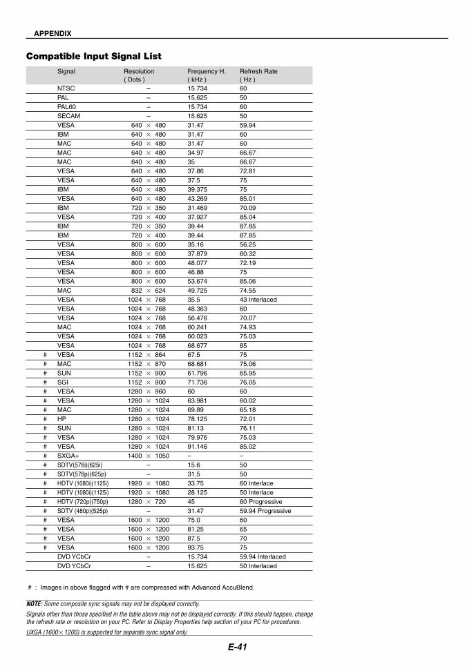
E-41
APPENDIX
Compatible Input Signal List
Signal Resolution Frequency H. Refresh Rate( Dots ) ( kHz ) ( Hz )
NTSC – 15.734 60PAL – 15.625 50PAL60 – 15.734 60SECAM – 15.625 50VESA 640 � 480 31.47 59.94IBM 640 � 480 31.47 60MAC 640 � 480 31.47 60MAC 640 � 480 34.97 66.67MAC 640 � 480 35 66.67VESA 640 � 480 37.86 72.81VESA 640 � 480 37.5 75IBM 640 � 480 39.375 75VESA 640 � 480 43.269 85.01IBM 720 � 350 31.469 70.09VESA 720 � 400 37.927 85.04IBM 720 � 350 39.44 87.85IBM 720 � 400 39.44 87.85VESA 800 � 600 35.16 56.25VESA 800 � 600 37.879 60.32VESA 800 � 600 48.077 72.19VESA 800 � 600 46.88 75VESA 800 � 600 53.674 85.06MAC 832 � 624 49.725 74.55VESA 1024 � 768 35.5 43 InterlacedVESA 1024 � 768 48.363 60VESA 1024 � 768 56.476 70.07MAC 1024 � 768 60.241 74.93VESA 1024 � 768 60.023 75.03VESA 1024 � 768 68.677 85
# VESA 1152 � 864 67.5 75# MAC 1152 � 870 68.681 75.06# SUN 1152 � 900 61.796 65.95# SGI 1152 � 900 71.736 76.05# VESA 1280 � 960 60 60# VESA 1280 � 1024 63.981 60.02# MAC 1280 � 1024 69.89 65.18# HP 1280 � 1024 78.125 72.01# SUN 1280 � 1024 81.13 76.11# VESA 1280 � 1024 79.976 75.03# VESA 1280 � 1024 91.146 85.02# SXGA+ 1400 � 1050 – –# SDTV(576i)(625i) – 15.6 50# SDTV(576p)(625p) – 31.5 50# HDTV (1080i)(1125i) 1920 � 1080 33.75 60 Interlace# HDTV (1080i)(1125i) 1920 � 1080 28.125 50 Interlace# HDTV (720p)(750p) 1280 � 720 45 60 Progressive# SDTV (480p)(525p) – 31.47 59.94 Progressive# VESA 1600 � 1200 75.0 60# VESA 1600 � 1200 81.25 65# VESA 1600 � 1200 87.5 70# VESA 1600 � 1200 93.75 75
DVD YCbCr – 15.734 59.94 InterlacedDVD YCbCr – 15.625 50 Interlaced
# : Images in above flagged with # are compressed with Advanced AccuBlend.
NOTE: Some composite sync signals may not be displayed correctly.
Signals other than those specified in the table above may not be displayed correctly. If this should happen, changethe refresh rate or resolution on your PC. Refer to Display Properties help section of your PC for procedures.
UXGA (1600�1200) is supported for separate sync signal only.

E-42
TravelCare Guide
TravelCare - a service for international travelersThis product is eligible for "TravelCare", NEC's unique international war-ranty.Please note that TravelCare coverage differs in part from coverage un-der the warranty included with the product.
Services offered with TravelCareThis warranty allows customers to receive service on their product atthe NEC and NEC-designated service stations in the countries listedherein when temporarily traveling internationally for business or plea-sure.For details on services offered by the different service stations, pleaserefer to the "List of TravelCare Outlets" below.
1 Repair servicesThe product will be repaired and delivered within 10 business days,not including shipping time.During the term of warranty, the cost of maintenance parts, laborcosts for repairs and shipping costs within the service station's cov-erage area are covered by the warranty.
2 Replacement product rental serviceIf the customer desires, he or she can rent a replacement productwhile the original product is being repaired.Fee: US$200 for 12 daysThis fee must be paid at the local service station in cash or creditcard.The $200 rental fee is non-refundable even if the customer rents itless than 12 days before returning.The replacement product will be delivered within 3 business days.If the customer did not return the replacement product within 12 days,the customer will be charged the price of the unit.If the customer returned the replacement product in a faulty or dam-aged condition, the repair cost will be charged to the customer.Note that this service is not offered in all countries and regions. Pleaserefer to the "List of TravelCare Outlets".In addition, this replacement product rental service is not offered af-ter the product's warranty has expired.
Term of warranty1
a. Upon presentation of the warranty or receipt received upon pur-chase:
Valid for the term indicated on the warranty or the normal term ofwarranty for the country of purchase.
b. When only the product is brought in:
Valid for a period of within 14 months of the date of manufactureindicated by the serial number attached to the product.
2 When a product whose term of warranty is expired is brought in:
Repairs will be offered for a fee. In this case the customer is noteligible for the replacement product rental service.
3 In the following cases, repairs may be charged, even if the product'swarranty is still in effect:
1) If the term of warranty, model name, serial number and name ofthe store of purchase are not indicated on the warranty or havebeen altered.
2) Problems or damage caused by dropping or shocks during ship-ment or movement by the customer or by improper handling bythe customers.
3) Problems or damage caused by improper usage or unwarrant-able alterations or repairs by the customer.
4) Problems or damage caused by fire, salt damage, gas damage,earthquakes, lightning damage, storm or flood damage or othernatural disasters or such external factors as dust, cigarettesmoke, abnormal voltage, etc.
5) Problems or damage caused by use in hot or humid places, invehicles, boats or ships, etc.
6) Problems or damage caused by expendable supplies or devicesconnected to the product other than those designated by NEC.
7) Problems caused by natural consumption, wear or deteriorationof parts under normal usage conditions.
8) Problems or damage to lamps and other expendable supplies,included parts or optional parts.
9) Other conditions stipulated in the warranty included with the prod-uct also apply.
NOTE: The product can be used overseas with voltages of 100 to 120V and 200to 240V by using a power cable suited for the standards and power source volt-age of the country in which the product is being used.
List of TravelCare OutletsThis list applies as of June 1, 2002.For the most up-to-date information, please refer to the websites of theservice stations in the various countries on the List of TravelCare Out-lets or to the NEC website at http://www.nec-pj.com.
In EuropeNEC Europe, Ltd. / European Technical Centre
Address: Unit G, Stafford Park 12, Telford TF3 3BJ, U.K.Telephone: +44 1952 237000Fax Line: +44 1952 237006Email Address: [email protected] Address: http://www.neceur.com
(Regions Covered)EU: Austria*, Belgium*, Denmark*, Finland*, France*, Germany*,
Greece*, Ireland*, Italy*, Luxembourg*, The Netherlands*,Portugal*, Spain*, Sweden* and the United Kingdom*
EEA: Norway*, Iceland and Liechtenstein
In North AmericaNEC Solutions (America), Inc.
Address: 1250 Arlington Heights Road, Itasca,Illinois 60143, U.S.A.
Telephone: +1 800 836 0655Fax Line: +1 800 356 2415Email Address: [email protected] Address: http://www.necvisualsystems.com
(Regions Covered)U.S.A. *, Canada*
In OceaniaNEC Australia Pty., Ltd.
Address: New South Wales;184 Milperra Road, Reversby 2212
Victoria;480 Princess Hwy Noble Park 3174
South Australia;84A Richmond Road, Keswick 5035
Queensland;116 Ipswich Road, Woollongabba 4102
Western Australia;45 Sarich Court Osborne Park 6017
Telephone: 131 632 (from domestic)+61 8 8375 5706 (from overseas)
Fax Line: +61 8 8375 5757Email Address: [email protected] Address: http://www.nec.com.au
(Regions Covered)Australia*, New Zealand
APPENDIX

E-43
In Asia and Middle EastNEC Viewtechnology, Ltd.
Address: 686-1, Nishioi, Oi-Machi, Ashigarakami-Gun,Kanagawa 258-0017, Japan
Telephone: +81 465 85 2369Fax Line: +81 465 85 2393Email Address: [email protected] Address: http://www.nec-pj.com
(Regions Covered)Japan*
NEC Hong Kong Ltd.Address: 11th Floor, Tower B, New Mandarin Plaza, 14
Science Museum Road,Tsim Sha Tsui East, Kowloon, Hong Kong
Telephone: +852 2369 0335Fax Line: +852 2795 6618Email Address: [email protected] Address: http://www.nec.com.hk
(Regions Covered)Hong Kong
NEC Taiwan Ltd.Address: 7F, No.167, SEC.2, Nan King East Road, Taipei,
Taiwan, R.O.C.Telephone: +886 2 8500 1734Fax Line: +886 2 8500 1420Email Address: [email protected] Address: http://www.nec.com.tw
(Regions Covered)Taiwan
NEC Singapore Pte. LtdAddress: 401 Commonwealth Drive, #07-02, Haw Par
Technocentre, Singapore 149598Telephone: +65 6 273 8333Fax Line: +65 6 274 2226Email Address: [email protected] Address: http://www.nec.com.sg
(Regions Covered)Singapore
Hyosung Data System, Ltd.Address: 7th Floor, Cheongdam Building, 52,
Cheongdam-Dong,Kangnam-Ku, Seoul, Korea 135-100
Telephone: +82 2 510 0234Fax Line: +82 2 540 3590Email Address: [email protected]
(Regions Covered)South Korea
Lenso Communication Co., Ltd.Address: 292 Lenso House 4, 1st Floor, Srinakarin Road,
Huamark, Bangkapi, Bangkok 10240, ThailandTelephone: +66 2 375 2425Fax Line: +66 2 375 2434Email Address: [email protected] Address: http://www.lenso.com
(Regions Covered)Thailand
ABBA Electronics L.L.C.Address: Tariq Bin Ziyad Road, P.O.Box 327, Dubai,
United Arab EmiratesTelephone: +971 4 371800Fax Line: +971 4 364283Email Address: [email protected]
(Regions Covered)United Arab Emirates
Samir Photographic SuppliesAddress: P.O.Box 599, Jeddah 21421, Saudi ArabiaTelephone: +966 2 6828219Fax Line: +966 2 6830820Email Address: [email protected]
(Regions Covered)Saudi Arabia
NOTE: In countries designated with an asterisk(*), replacement product rentalservice are offered.
APPENDIX

E-44
TO: NEC or NEC's Authorized Service Station:FM:
(Company & Name with signature)
Dear Sir (s),
I would like to apply your TravelCare Service Program based on attached registration and qualification sheet and agree with your
following conditions, and also the Service fee will be charged to my credit card account, if I don't return the Loan units within the
specified period. I also confirm following information is correct. Regards.
Application Sheet for TravelCare Service Program
Date: / / , P-1/ ,
Country,
product purchased :
User's Company Name :
User's Company Address :
Phone No., Fax No. :
User's Name :
User's Address :
Phone No., Fax No. :
Local Contact office :
Local Contact office Address :
Phone No., Fax No. :
User's Model Name :
Date of Purchase :
Serial No. on cabinet :
Problem of units per User :
Required Service : (1) Repair and Return (2) Loan unit
Requested period of Loan unit :
Payment method : (1) Credit Card (2) Travelers Cheque (3) Cash
In Case of Credit Card :
Card No. w/Valid Date :
APPENDIX

E-45
Condition of your TravelCare Service ProgramEnduser is requested to understand following conditions of TravelCareService Program and complete the necessary information on theapplication sheet.
1. Service Options:There are 3 types of "Service" available. Enduser has to understandfollowing condition and is required to fill in the Application Sheet.
1) Repair and Return:
The 'Faulty unit' is sent or collected from the customer. It is repairedand returned within 10 days to the customer, excluding transport time.
There may have a case, repair and return can't be done by NECAuthorized Service Station, because of shortage of spare parts dueto same model is not sold in the territory.
2) Repair and Return with Loan: (This service is limited to some Ser-vice Stations)
This service is offered to the Enduser, who cannot wait until their unitis repaired.
The customer can borrow a unit for $200 up to 12 days. Customerthen sends in inoperable unit to nearest NEC Authorized ServiceStation for service. In order to prevent collection problem, Enduser isrequired to fill in Application Sheet.
Enduser needs to confirm the availability of the Service to NEC Au-thorized Service Stations.
3) Loan Only:
For this service, NEC Authorized Service Station supplies the cus-tomer with a loan unit for US$200 up to 12 days. Customer keeps theinoperable unit and when customer returns home, customer arrangesto have the projector serviced in the home country.
2. Warranty Exclusions:This program does not apply if the Projector's serial number has beendefaced, modified or removed.If, in the judgement of NEC Authorized Service Station or its agent thedefects or failures result from any cause other than fair wear and tear orNEC neglect, or fault including the following without limitation:
1) Accidents, transportation, neglect, misuse, abuse, water, dust, smokeor default of or by the Customer its employees or agents or any thirdparty;
2) Failure or fluctuation of electrical power, electrical circuitry, air condi-tioning, humidity control or other environmental conditions such asuse it in smoking area;
3) Any fault in the attachments or associated products or components(whether or not supplied by NEC or its agents which do not form partof the Product covered by this warranty);
4) Any act of God, fire, flood, war, act of violence or any similar occur-rence;
5) Any attempt by any person other than any person authorized by NECto adjust, modify, repair, install or service the product.
6) Any Cross-border charges such as, duty, insurance, tax etc.
3. Charges for Warranty Exclusions and Out of Warranty Case:In case faulty unit is under warranty exclusions case or under Out ofWarranty period, NEC Authorized Service Station will Inform estimationof actual service cost to the Enduser with reason.
4. Dead on Arrival (DOA):Enduser must take this issue up with their original supplier in the coun-try of purchase.NEC Authorized Service Station will repair the DOA unit as a Warrantyrepair, but will not exchange DOA unit with new units.
5. Loan Service Charges and Conditions:Upon acceptance of this NEC Projector, Customer agrees to assumeliability for this loan unit.
The current cost of use of this loan unit is $200.00 USD for 12 calendardays.If Customer does not return the unit within the 12 calendar days, Cus-tomer will be charged the next highest cost up to and including the fulllist price to Credit Cards, which price will be informed by NEC Autho-rized Service Stations. Please see the attached listing of contacts foreach country to arrange for pickup of the loan unit.
If you return to their country of origin with the loan unit, you will becharged additional freight to return the unit to the loaning country.
Thank you for your understanding of this program.
APPENDIX
Ver. 1 9/03