Plasma Welding of NiTi to NiTi, Stainless Steel and Hastelloy C276
5
ASM Materials Solutions 2003 Conference, Pittsburgh, Pennsylvania, USA, 13-15 October 2003 Plasma Welding of NiTi to NiTi, Stainless Steel and Hastelloy C276 Casper van der Eijk, Hans Fostervoll, Zuhair K. Sallom and Odd M. Akselsen SINTEF Materials Technology, Richard Birkelands vei 3A, N-7465, Trondheim, Norway Abstract NiTi alloys are known for their shape memory effect and their superelastic behavior. The past two decades, a lot of research has been done on these alloys. The number of applications where the material is used is however still limited to some niche markets, like the medical one. Widespread application of NiTi is partly restricted by the lack of knowledge on how to weld NiTi to NiTi and to other materials. In this paper, the results form welding experiments of NiTi to NiTi, stainless steel and Hastelloy C276 are presented. The welds are characterized by DSC, optical microscopy and Field Emission SEM. The investigation of the NiTi-NiTi welds show that there is no compositional variation of the material through the weld. The mechanical properties are however significantly deteriorated after welding. The investigation of the dissimilar welds shows that the mixed zone of these welds contains a number of brittle phases, deteriorating the quality of the weld. Introduction Successful commercialization of products using shape memory alloys will require that these alloys can be joined using processes such as welding, brazing and soldering. The development of joining processes for shape memory alloys will open up for new low cost applications. For example, by joining two shape memory alloys with different transformation temperatures, a complex actuator which works at various temperatures can be produced in a simple tiny component 1 . Joining of shape memory alloys is however challenging. In the case of welding of NiTi to NiTi, the properties to be matched between the base metal and joint region are the chemical composition and the microstructure, which dictate the shape memory response. This is where, fundamentally, the joining of shape memory alloys is different from that of conventional structural alloys such as steel, aluminum and titanium alloys. In conventional alloys, successful joints are obtained despite differences between the chemical compositions and the microstructure of weld metal and heat affected zone on one hand and the base metal on the other. In the case of a NiTi-NiTi weld, this is not the case, matching of chemical composition, microstructure and transformation temperatures is very important in addition to matching the mechanical properties and corrosion resistance 2 . During fusion welding of NiTi alloys, embrittlement may occur due to the reaction with oxygen, nitrogen and hydrogen at high temperatures. In addition, precipitation of brittle intermetallic compounds such as Ti 2 Ni and TiNi 3 during solidification can have adverse effects on both strength and shape memory characteristics of the material 3 . Ikai et al. describe the TIG welding of NiTi wire and sheet. Heat treatment and training of the wire close the weld are necessary to recover the shape memory effect after welding 1 . Good results have been reported using laser welding. Only minor changes in the transformation temperatures, no deterioration in shape recovery and a higher strength, but lower ductility are observed after laser welding of 2 mm thick NiTi sheet with a 5 kW continuous-wave CO 2 laser 4 . When thin (0.5 mm) sheets of NiTi are welded using a Nd-YAG laser, the shape memory effect is preserved. However, the strength is decreased and the temperature window for use of the pseudoelastic effect is narrowed 5 . Schlossmacher et al. describe the Nd-YAG laser welding of thin (0.5mm) pseudoelastic Ti-51.5at%Ni sheet. They show that the pseudoelastic plateau is preserved after welding. The ultimate tensile strength of the welded material is still 80% of the base material with an elongation to fracture of 8.4% 6 . Solid state welding processes, like friction welding could be considered as a suitable method since prevention of grain growth and good mechanical properties can be expected. In addition, friction welding of NiTi can be carried out in air
Transcript of Plasma Welding of NiTi to NiTi, Stainless Steel and Hastelloy C276
ASM Materials Solutions 2003 Conference, Pittsburgh, Pennsylvania, USA, 13-15 October 2003
Plasma Welding of NiTi to NiTi, Stainless Steel and Hastelloy C276
Casper van der Eijk, Hans Fostervoll, Zuhair K. Sallom and Odd M. Akselsen SINTEF Materials Technology, Richard Birkelands vei 3A, N-7465, Trondheim, Norway
Abstract
NiTi alloys are known for their shape memory effect
and their superelastic behavior. The past two decades, a lot of research has been done on these alloys. The number of applications where the material is used is however still limited to some niche markets, like the medical one. Widespread application of NiTi is partly restricted by the lack of knowledge on how to weld NiTi to NiTi and to other materials.
In this paper, the results form welding experiments of
NiTi to NiTi, stainless steel and Hastelloy C276 are presented. The welds are characterized by DSC, optical microscopy and Field Emission SEM. The investigation of the NiTi-NiTi welds show that there is no compositional variation of the material through the weld. The mechanical properties are however significantly deteriorated after welding. The investigation of the dissimilar welds shows that the mixed zone of these welds contains a number of brittle phases, deteriorating the quality of the weld.
Introduction
Successful commercialization of products using shape
memory alloys will require that these alloys can be joined using processes such as welding, brazing and soldering. The development of joining processes for shape memory alloys will open up for new low cost applications. For example, by joining two shape memory alloys with different transformation temperatures, a complex actuator which works at various temperatures can be produced in a simple tiny component1. Joining of shape memory alloys is however challenging.
In the case of welding of NiTi to NiTi, the properties
to be matched between the base metal and joint region are the chemical composition and the microstructure, which dictate the shape memory response. This is where,
fundamentally, the joining of shape memory alloys is different from that of conventional structural alloys such as steel, aluminum and titanium alloys. In conventional alloys, successful joints are obtained despite differences between the chemical compositions and the microstructure of weld metal and heat affected zone on one hand and the base metal on the other. In the case of a NiTi-NiTi weld, this is not the case, matching of chemical composition, microstructure and transformation temperatures is very important in addition to matching the mechanical properties and corrosion resistance2.
During fusion welding of NiTi alloys, embrittlement may
occur due to the reaction with oxygen, nitrogen and hydrogen at high temperatures. In addition, precipitation of brittle intermetallic compounds such as Ti2Ni and TiNi3 during solidification can have adverse effects on both strength and shape memory characteristics of the material3.
Ikai et al. describe the TIG welding of NiTi wire and sheet.
Heat treatment and training of the wire close the weld are necessary to recover the shape memory effect after welding1. Good results have been reported using laser welding. Only minor changes in the transformation temperatures, no deterioration in shape recovery and a higher strength, but lower ductility are observed after laser welding of 2 mm thick NiTi sheet with a 5 kW continuous-wave CO2 laser4. When thin (0.5 mm) sheets of NiTi are welded using a Nd-YAG laser, the shape memory effect is preserved. However, the strength is decreased and the temperature window for use of the pseudoelastic effect is narrowed5. Schlossmacher et al. describe the Nd-YAG laser welding of thin (0.5mm) pseudoelastic Ti-51.5at%Ni sheet. They show that the pseudoelastic plateau is preserved after welding. The ultimate tensile strength of the welded material is still 80% of the base material with an elongation to fracture of 8.4%6.
Solid state welding processes, like friction welding could
be considered as a suitable method since prevention of grain growth and good mechanical properties can be expected. In addition, friction welding of NiTi can be carried out in air
ASM Materials Solutions 2003 Conference, Pittsburgh, Pennsylvania, USA, 13-15 October 2003
without inert gas shielding whereas fusion welding is impossible without proper gas shielding. Friction welding of 6 mm rods has shown that satisfactory welds can be obtained provided that heat treatment is performed after welding to minimize the variation in the transformation temperatures of the welds with respect to those of the base metal3.
Materials and Experimental Procedure
Materials Nickel and titanium were weighed according to the
target compositions of 50/50 at% (equi-atomic) ratio which corresponds with 55wt% Ni and 45wt% Ti. The Ni had a 99% purity with 0.0075%C, 0.0062%O and 0.0004%N. The titanium pieces (ASTM B 265-90 grade 2) contained 0.02%C, 0.14%O, 0.010%N and 0.07%Fe. The alloys were made by melting in a graphite crucible 50 mm in diameter and 180 mm height, using a Balzer vacuum induction furnace. The melt was cast in a copper mould containing 6 cylindrical cavities of 15 mm in diameter, 98 mm height. After casting, the material was heat treated in vacuum at 950°C for 72 hours.
The chemical analysis of the NiTi alloy is shown in
Table 1. Some Ni has been lost during the melting process. NiTi strips (1mm thick, 15mm wide) are machined from rods using electrical discharge machining. The strips are sand blasted and then ground using 500 mesh emery papers to remove any surface irregularities. Standard Hastelloy C276, which is a Ni-based alloy containing Mo, Cr, Fe and W, and an ASTM A240 stainless steel were used for the dissimilar welds. A filler wire was used in one of the NiTi-stainless steel welds. The composition is shown in Table 2. Welded specimens were examined by optical microscopy and SEM (Hitachi 4300 FE-SEM).
Table 1. Analyzed composition of the NiTi casting (wt%)
Ni Ti C O N 53.7 46.2 0.050 0.048 0.0003
Table 2. Composition of the filler wire used for the NiTi-
stainless steel joint (wt%) Ni Cr Mo Fe 63 21 9 7
Welding Procedure
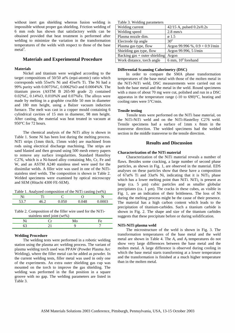
The welding tests were performed in a robotic welding station using the plasma arc welding process. The variant of plasma welding torch used was PPAW (Powder Plasma Arc Welding), where the filler metal can be added as powder. In the current welding tests, filler metal was used in only one of the experiments. An extra outer shielding gas cup was mounted on the torch to improve the gas shielding. The welding was performed in the flat position in a square groove with no gap. The welding parameters are listed in Table 3.
Table 3. Welding parameters Welding current 42/15 A, pulsed 0.2s/0.2s Welding speed 2.8 mm/s Plasma nozzle dim. ø 1.5 Electrode tip angle 30o
Plasma gas type, flow Argon 99.996 %, 0.9 + 0.9 l/min Shielding gas type, flow Argon 99.996, 5 l/min Backing gas + outer shielding Argon Work distance, torch angle 6 mm, 10o forehand Differential Scanning Calorimetry (DSC)
In order to compare the SMA phase transformation temperatures of the base metal with those of the molten metal in the NiTi-NiTi weld, DSC measurements were carried out on both the base metal and the metal in the weld. Round specimens with a mass of about 70 mg were cut, polished and run in a DSC apparatus in the temperature range (-10 to 690)°C, heating and cooling rates were 5°C/min.
Tensile testing
Tensile tests were performed on the NiTi base material, on the NiTi-NiTi weld and on the NiTi-Hastelloy C276 weld. Tensile specimens had a surface of 1mm x 8mm in the transverse direction. The welded specimens had the welded section in the middle transverse to the tensile direction.
Results and Discussion
Characterization of the NiTi material
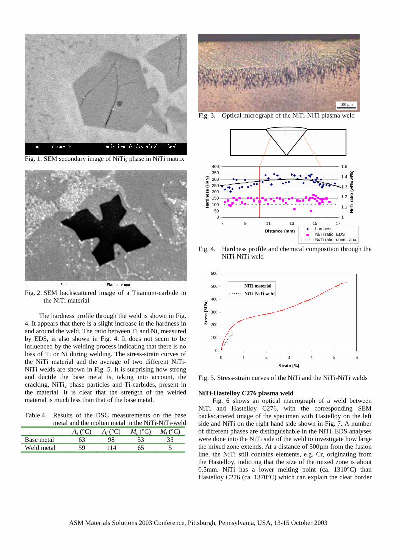
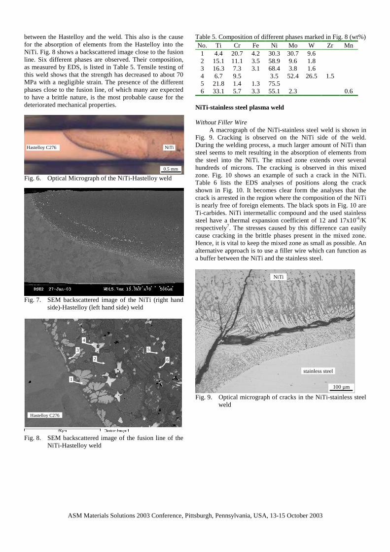
Characterization of the NiTi material reveals a number of flaws. Besides some cracking, a large number of second phase particles, as shown in Fig. 1, are observed in the material. EDS analyses on these particles show that these have a composition of 67at% Ti and 33at% Ni, indicating that it is NiTi2 phase which has a lower melting point than NiTi. NiTi2 is present as large (ca. 5 µm) cubic particles and as smaller globular precipitates (ca. 1 µm). The cracks in these cubes, as visible in Fig. 1, are an indication of their brittleness. The loss of Ni during the melting process might be the cause of their presence. The material has a high carbon content which leads to the precipitation of titanium-carbides. Such a titanium carbide is shown in Fig. 2. The shape and size of the titanium carbides suggests that these precipitate before or during solidification. NiTi-NiTi plasma weld
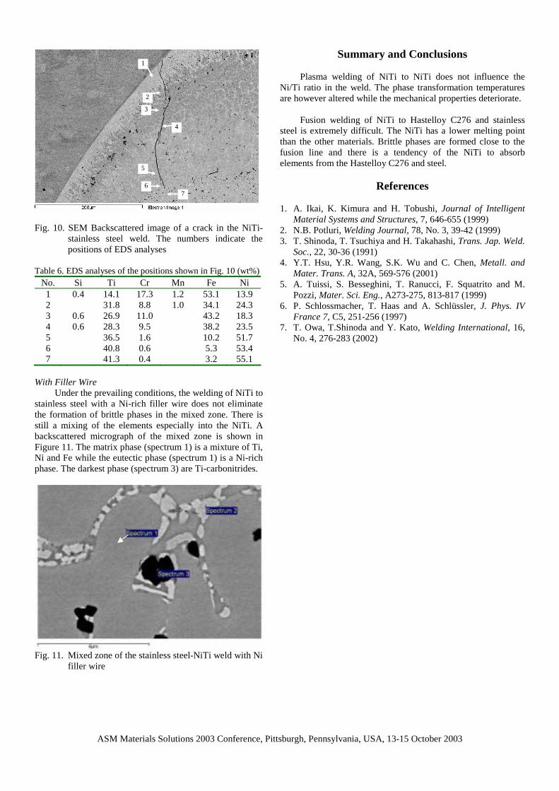
The microstructure of the weld is shown in Fig. 3. The transformation temperatures of the base metal and the weld metal are shown in Table 4. The As and Af temperatures do not show very large differences between the base metal and the molten metal. A large difference is observed during cooling in which the base metal starts transforming at a lower temperature and the transformation is finished at a much higher temperature than in the molten metal.
ASM Materials Solutions 2003 Conference, Pittsburgh, Pennsylvania, USA, 13-15 October 2003
Fig. 1. SEM secondary image of NiTi2 phase in NiTi matrix
Fig. 2. SEM backscattered image of a Titanium-carbide in
the NiTi material The hardness profile through the weld is shown in Fig.
4. It appears that there is a slight increase in the hardness in and around the weld. The ratio between Ti and Ni, measured by EDS, is also shown in Fig. 4. It does not seem to be influenced by the welding process indicating that there is no loss of Ti or Ni during welding. The stress-strain curves of the NiTi material and the average of two different NiTi-NiTi welds are shown in Fig. 5. It is surprising how strong and ductile the base metal is, taking into account, the cracking, NiTi2 phase particles and Ti-carbides, present in the material. It is clear that the strength of the welded material is much less than that of the base metal. Table 4. Results of the DSC measurements on the base
metal and the molten metal in the NiTi-NiTi-weld As (°C) Af (°C) Ms (°C) Mf (°C) Base metal 63 98 53 35 Weld metal 59 114 65 5
100 µm
Fig. 3. Optical micrograph of the NiTi-NiTi plasma weld
050
100150200250300350400
7 9 11 13 15 17
Distance (mm)
Hard
ness
(HVN
)
1
1.1
1.2
1.3
1.4
1.5
Ni-T
i rat
io (w
t%/w
t%)
hardnessNi/Ti ratio: EDSNi/Ti ratio: chem. ana.
Fig. 4. Hardness profile and chemical composition through the NiTi-NiTi weld
0
100
200
300
400
500
600
0 1 2 3 4 5 6
Strain [%]
Stre
ss [M
Pa]
NiTi materialNiTi-NiTi weld
Fig. 5. Stress-strain curves of the NiTi and the NiTi-NiTi welds NiTi-Hastelloy C276 plasma weld
Fig. 6 shows an optical macrograph of a weld between NiTi and Hastelloy C276, with the corresponding SEM backscattered image of the specimen with Hastelloy on the left side and NiTi on the right hand side shown in Fig. 7. A number of different phases are distinguishable in the NiTi. EDS analyses were done into the NiTi side of the weld to investigate how large the mixed zone extends. At a distance of 500µm from the fusion line, the NiTi still contains elements, e.g. Cr, originating from the Hastelloy, indicting that the size of the mixed zone is about 0.5mm. NiTi has a lower melting point (ca. 1310°C) than Hastelloy C276 (ca. 1370°C) which can explain the clear border
ASM Materials Solutions 2003 Conference, Pittsburgh, Pennsylvania, USA, 13-15 October 2003
between the Hastelloy and the weld. This also is the cause for the absorption of elements from the Hastelloy into the NiTi. Fig. 8 shows a backscattered image close to the fusion line. Six different phases are observed. Their composition, as measured by EDS, is listed in Table 5. Tensile testing of this weld shows that the strength has decreased to about 70 MPa with a negligible strain. The presence of the different phases close to the fusion line, of which many are expected to have a brittle nature, is the most probable cause for the deteriorated mechanical properties.
0.5 mm
Hastelloy C276 NiTi
Fig. 6. Optical Micrograph of the NiTi-Hastelloy weld
Fig. 7. SEM backscattered image of the NiTi (right hand
side)-Hastelloy (left hand side) weld
Hastelloy C276
1
2
3
4
5
6
Fig. 8. SEM backscattered image of the fusion line of the
NiTi-Hastelloy weld
Table 5. Composition of different phases marked in Fig. 8 (wt%) No. Ti Cr Fe Ni Mo W Zr Mn 1 4.4 20.7 4.2 30.3 30.7 9.6 2 15.1 11.1 3.5 58.9 9.6 1.8 3 16.3 7.3 3.1 68.4 3.8 1.6 4 6.7 9.5 3.5 52.4 26.5 1.5 5 21.8 1.4 1.3 75.5 6 33.1 5.7 3.3 55.1 2.3 0.6
NiTi-stainless steel plasma weld Without Filler Wire
A macrograph of the NiTi-stainless steel weld is shown in Fig. 9. Cracking is observed on the NiTi side of the weld. During the welding process, a much larger amount of NiTi than steel seems to melt resulting in the absorption of elements from the steel into the NiTi. The mixed zone extends over several hundreds of microns. The cracking is observed in this mixed zone. Fig. 10 shows an example of such a crack in the NiTi. Table 6 lists the EDS analyses of positions along the crack shown in Fig. 10. It becomes clear form the analyses that the crack is arrested in the region where the composition of the NiTi is nearly free of foreign elements. The black spots in Fig. 10 are Ti-carbides. NiTi intermetallic compound and the used stainless steel have a thermal expansion coefficient of 12 and 17x10-6/K respectively7. The stresses caused by this difference can easily cause cracking in the brittle phases present in the mixed zone. Hence, it is vital to keep the mixed zone as small as possible. An alternative approach is to use a filler wire which can function as a buffer between the NiTi and the stainless steel.
100 µm
stainless steel
NiTi
Fig. 9. Optical micrograph of cracks in the NiTi-stainless steel weld
ASM Materials Solutions 2003 Conference, Pittsburgh, Pennsylvania, USA, 13-15 October 2003
1
2
3
4
5
6 7
Fig. 10. SEM Backscattered image of a crack in the NiTi-
stainless steel weld. The numbers indicate the positions of EDS analyses
Table 6. EDS analyses of the positions shown in Fig. 10 (wt%)
No. Si Ti Cr Mn Fe Ni 1 0.4 14.1 17.3 1.2 53.1 13.9 2 31.8 8.8 1.0 34.1 24.3 3 0.6 26.9 11.0 43.2 18.3 4 0.6 28.3 9.5 38.2 23.5 5 36.5 1.6 10.2 51.7 6 40.8 0.6 5.3 53.4 7 41.3 0.4 3.2 55.1
With Filler Wire
Under the prevailing conditions, the welding of NiTi to stainless steel with a Ni-rich filler wire does not eliminate the formation of brittle phases in the mixed zone. There is still a mixing of the elements especially into the NiTi. A backscattered micrograph of the mixed zone is shown in Figure 11. The matrix phase (spectrum 1) is a mixture of Ti, Ni and Fe while the eutectic phase (spectrum 1) is a Ni-rich phase. The darkest phase (spectrum 3) are Ti-carbonitrides.
Fig. 11. Mixed zone of the stainless steel-NiTi weld with Ni
filler wire
Summary and Conclusions
Plasma welding of NiTi to NiTi does not influence the Ni/Ti ratio in the weld. The phase transformation temperatures are however altered while the mechanical properties deteriorate.
Fusion welding of NiTi to Hastelloy C276 and stainless
steel is extremely difficult. The NiTi has a lower melting point than the other materials. Brittle phases are formed close to the fusion line and there is a tendency of the NiTi to absorb elements from the Hastelloy C276 and steel.
References 1. A. Ikai, K. Kimura and H. Tobushi, Journal of Intelligent
Material Systems and Structures, 7, 646-655 (1999) 2. N.B. Potluri, Welding Journal, 78, No. 3, 39-42 (1999) 3. T. Shinoda, T. Tsuchiya and H. Takahashi, Trans. Jap. Weld.
Soc., 22, 30-36 (1991) 4. Y.T. Hsu, Y.R. Wang, S.K. Wu and C. Chen, Metall. and
Mater. Trans. A, 32A, 569-576 (2001) 5. A. Tuissi, S. Besseghini, T. Ranucci, F. Squatrito and M.
Pozzi, Mater. Sci. Eng., A273-275, 813-817 (1999) 6. P. Schlossmacher, T. Haas and A. Schlüssler, J. Phys. IV
France 7, C5, 251-256 (1997) 7. T. Owa, T.Shinoda and Y. Kato, Welding International, 16,
No. 4, 276-283 (2002)