Pinpoint Tests — OSC Equipped Worldwide Diagnostic System ...Transmission Fluid Pressure 418-F205...
24
307-01-1 307-01-1 Automatic Transmission — 5R55S Special Tool(s) DIAGNOSIS AND TESTING Worldwide Diagnostic System Pinpoint Tests — OSC Equipped (WDS) Vehicles 418-F224 New Generation Star (NGS) Special Tool(s) Tester Transmission Fluid Pressure 418-F205 or equivalent Gauge 307-004 (T57L-77820-A) MLP-TR Cable 418-F107 (007-00111) or equivalent 73 III Automotive Meter 105-R0057 or equivalent Transmission Tester 307-F016 (007-00130) or equivalent Trans Tester TR/MLP Overlay and Manual 007-00131 or equivalent Shift Solenoid Pre-Diagnosis Any time an electrical connector or solenoid body is disconnected, inspect the connector for terminal condition, corrosion and contamination. Also inspect (Continued) the connector seal for damage. Clean, repair or install new as necessary. Use the following shift solenoid operation information when carrying out Pinpoint Test A. Solenoid Operation Chart 5R55S Solenoid States Base Gearshift PCM Comm- SSA SSB SSC SSD PCA PCB PCC Selector Position anded Gear P/N P/N On Off Off On L a H/L b L a R R On Off Off On H/L b L a H c D5 1 On Off Off On H c H/L b L a 2 On Off On On H/L b H c L a 3 On On Off On H c H/L b L a 4 Off Off Off On H c H/L b H c 5 Off Off On On H c H c H c D4 1 On Off Off On H c H/L b L a 2 On Off On On H/L b H c L a 3 On On Off On H c H/L b L a 4 Off Off Off Off H/L b H c H c +/- 1 On Off Off On H c H/L b L a Copyright 2003, Ford Motor Company Last updated: 6/19/2003 2004 Thunderbird, 8/2003
Transcript of Pinpoint Tests — OSC Equipped Worldwide Diagnostic System ...Transmission Fluid Pressure 418-F205...

307-01-1 307-01-1Automatic Transmission — 5R55S
Special Tool(s)DIAGNOSIS AND TESTING
Worldwide Diagnostic SystemPinpoint Tests — OSC Equipped(WDS)Vehicles418-F224
New Generation Star (NGS)Special Tool(s)Tester
Transmission Fluid Pressure 418-F205 or equivalentGauge307-004 (T57L-77820-A)
MLP-TR Cable418-F107 (007-00111) orequivalent
73 III Automotive Meter105-R0057 or equivalent
Transmission Tester307-F016 (007-00130) orequivalent
Trans Tester TR/MLP Overlayand Manual007-00131 or equivalent
Shift Solenoid Pre-Diagnosis
Any time an electrical connector or solenoid body isdisconnected, inspect the connector for terminalcondition, corrosion and contamination. Also inspect(Continued)the connector seal for damage. Clean, repair orinstall new as necessary.
Use the following shift solenoid operationinformation when carrying out Pinpoint Test A.
Solenoid Operation Chart
5R55S Solenoid StatesBase Gearshift PCM Comm-SSA SSB SSC SSD PCA PCB PCCSelector Position anded Gear
P/N P/N On Off Off On L a H/L b La
R R On Off Off On H/Lb La H c
D5 1 On Off Off On Hc H/Lb La
2 On Off On On H/Lb Hc La
3 On On Off On Hc H/Lb La
4 Off Off Off On Hc H/Lb Hc
5 Off Off On On Hc Hc Hc
D4 1 On Off Off On Hc H/Lb La
2 On Off On On H/Lb Hc La
3 On On Off On Hc H/Lb La
4 Off Off Off Off H/Lb Hc Hc
+/- 1 On Off Off On Hc H/Lb La
Copyright 2003, Ford Motor CompanyLast updated: 6/19/2003 2004 Thunderbird, 8/2003

307-01-2 307-01-2Automatic Transmission — 5R55S
DIAGNOSIS AND TESTING (Continued)
Solenoid Operation Chart (Continued)
5R55S Solenoid StatesBase Gearshift PCM Comm-SSA SSB SSC SSD PCA PCB PCCSelector Position anded Gear
2 On Off On On H/Lb Hc La
3 On On Off On Hc H/Lb La
4 Off Off Off On Hc H/Lb Hc
5 Off Off On On Hc Hc Hc
3 3 On On Off Off Hc La H/Lb
2 2 On Off On Off Hc La H/Lb
1 1 On Off Off Off Hc La H/Lb
a Low line pressureb High/low pressure — PCM controlledc High line pressure
Transmission Range SelectorShift Solenoid Failure Mode Chart ‘‘AlwaysLever PositionOff’’ SSC Always
D5 D4‘‘OFF’’:Failed OFF due to powertrain control module and/orvehicle wiring concerns, solenoid electrically, PCM Gear Actual Gear Obtained
Commandedmechanically or hydraulically stuck OFF.1 1 1
Transmission Range Selector2 1 1Lever PositionSSA Always3 3 3D5 D4‘‘OFF’’:4 4 4M a
PCM Gear Actual GearCommanded 5 4
1 3 3 a Manual2 2 2
3 3 3 Transmission Range SelectorLever Position4 4 4M a SSD Always
D5 D4‘‘OFF’’:5 5PCM Gear Actual Gear Obtained
a Manual Commanded
1 1/1M a 1/1Ma
Transmission Range Selector2 2Ma 2Ma
Lever PositionSSB Always3 3/3Ma 3Ma
D5 D4‘‘OFF’’:4 4/4Ma 4Ma
PCM Gear Actual Gear ObtainedCommanded 5 5
1 1 1 a Manual2 2 2
3 1 1 Shift Solenoid Failure Mode Chart ‘‘Always4 4 4M a On’’5 5 Failed OFF due to powertrain control module and/or
vehicle wiring concerns, solenoid electrically,a Manualmechanically or hydraulically stuck ON.
2004 Thunderbird, 8/2003

307-01-3 307-01-3Automatic Transmission — 5R55S
DIAGNOSIS AND TESTING (Continued)
Transmission Range Selector Transmission Range SelectorLever Position Lever PositionSSA Always SSD Always
D5 D4‘‘ON’’: D5 D4‘‘ON’’:
PCM Gear Actual Gear Obtained 4 4 4Commanded 5 5
1 1 1
2 2 2Pressure Control Solenoid Failure Mode
3 3 3 Chart ‘‘Always Low’’4 1 1M a
Transmission Range Selector5 2Lever Position
a Manual D5 D4PC A ‘‘Low’’:
PCM Gear Actual Gear ObtainedTransmission Range Selector Commanded
Lever PositionSSB Always 1 S a /1 1D5 D4‘‘ON’’:
2 2 2PCM Gear Actual Gear Obtained
3 Sa/1 1Commanded4 Sa/4 4M1 3 35 52 2 2
3 3 3 a Slips
4 4 4M a
Transmission Range Selector5 5Lever Position
a Manual D5 D4PC B ‘‘Low’’:
PCM Gear Actual Gear ObtainedTransmission Range Selector Commanded
Lever PositionSSC Always 1 1 1D5 D4‘‘ON’’:
2 1 1PCM Gear Actual Gear Obtained
3 3 3Commanded4 4 41 1/2 1/25 42 2 2
3 3/Ratio 1.16 3/Ratio 1.16
Transmission Range Selector4 4/5 4/5Lever Position
5 5D5 D4PC C ‘‘Low’’:
PCM Gear Actual Gear ObtainedTransmission Range Selector Commanded
Lever PositionSSD Always 1 1 1D5 D4‘‘ON’’:
2 2 2PCM Gear Actual Gear Obtained
3 3 3Commanded4 3 31 1 15 1.12 2 2
3 3 3
2004 Thunderbird, 8/2003

307-01-4 307-01-4Automatic Transmission — 5R55S
DIAGNOSIS AND TESTING (Continued)
Transmission Range SelectorPressure Control Solenoid Failure ModeLever PositionChart ‘‘Always High’’
D5 D4PC B ‘‘High’’:Transmission Range Selector
2 2 2Lever Position3 3 3D5 D4PC A ‘‘High’’:4 4 4M a
PCM Gear Actual Gear ObtainedCommanded 5 5
1 1 1 a Manual2 2 2
3 3 3 Transmission Range SelectorLever Position4 4 4M a
D5 D4PC C ‘‘High’’:5 5PCM Gear Actual Gear Obtained
a Manual Commanded
1 1 1Transmission Range Selector
2 2 2Lever Position3 3 3D5 D4PC B ‘‘High’’:4 4 4M a
PCM Gear Actual Gear ObtainedCommanded 5 5
1 1 1 a Manual
Pinpoint Tests
PINPOINT TEST A: SHIFT AND TORQUE CONVERTER CLUTCH SOLENOIDS
NOTE: Refer to the Transmission Vehicle Harness Connector illustration preceding thesepinpoint tests.
NOTE: Refer to the Internal Harness Diagram illustration preceding these pinpoint tests.
NOTE: Read and record all DTCs. All Digital TR Sensor and VSS DTCs must be repairedbefore entering Output State Control (OSC).
Test Step Result / Action to TakeA1 ELECTRONIC DIAGNOSTICS
• Key in OFF position.• Select PARK.• Check to make sure the transmission harness connector is fully
seated, terminals are fully engaged in connector and in goodcondition before proceeding.
• Connect the diagnostic tool.• Key in ON position.• Enter the following diagnostic mode on the diagnostic tool:
Diagnostic Data Link. Yes• Enter the following diagnostic mode on the diagnostic tool: PCM. REMAIN in Trans-Bench Mode. GO to A2.• Enter the following diagnostic mode on the diagnostic tool:Active Command Modes. No
• Enter the following diagnostic mode on the diagnostic tool: REPEAT procedure to enter Trans-BenchOutput State Control (OSC). Mode. If vehicle did not enter Trans-Bench
• Enter the following diagnostic mode on the diagnostic tool: Mode, REFER to thePowertrainTrans-Bench Mode. Control/Emissions Diagnosis (PC/ED)
• Does vehicle enter Trans-Bench Mode? manual for diagnosis of PCM or NGS.A2 WIGGLE TEST
• Remain in Trans-Bench Mode.• Select PIDs to be monitored.
(Continued)
2004 Thunderbird, 8/2003

307-01-5 307-01-5Automatic Transmission — 5R55S
DIAGNOSIS AND TESTING (Continued)PINPOINT TEST A: SHIFT AND TORQUE CONVERTER CLUTCH SOLENOIDS (Continued)
Test Step Result / Action to TakeA2 WIGGLE TEST (Continued)
PID Command PID Actual
SSA SSA
SSB SSB
SSC SSC
SSD SSD
TCC TCC
• Select ‘‘ON’’ to turn suspect solenoid on.• Press ‘‘SEND’’. Yes• Wiggle all wiring and connectors to the transmission. Monitor the REPAIR the circuit. TEST the system forsolenoid state for changes. normal operation.• Select ‘‘OFF’’ to turn solenoid off.• Press ‘‘SEND’’. No• Does the suspect solenoid(s) fault state change? GO to A3.
A3 SOLENOID FUNCTIONAL CHECK• Monitor each solenoid state. Yes• Turn each solenoid ON and OFF. GO to A4.• Does the solenoid turn ON and OFF when commanded and Nocan solenoid activation be heard? GO to A5.
A4 OSC TRANS-DRIVE MODE (GEAR OR TCC)• Carry out OSC Trans-Drive Mode. Yes• Select GEAR for shift solenoids or follow procedures for GEAR CLEAR all DTCs. ROAD TEST to verify if
as listed in this section. concern is still present. If concern is still• Select TCC for Torque Converter Clutch Solenoid. Follow present, REFER to Diagnosis By Symptom
procedures of TCC in Drive Mode as listed in this section. to diagnose shift or torque converter• Does the transmission upshift and downshift or torque concern.
converter engage/disengage when commanded? NoGO to A5.
A5 CHECK FOR BATTERY VOLTAGE• Disconnect: Transmission Vehicle Harness Connector.• Visually inspect all wires and connectors for damage.• Key in ON position.• Measure the voltage on pin 3 harness side and ground.
YesGO to A6.NoREPAIR the circuit. TEST for normal
• Is the voltage greater than 10 volts? operation.
(Continued)
2004 Thunderbird, 8/2003
307-01-6 307-01-6Automatic Transmission — 5R55S
DIAGNOSIS AND TESTING (Continued)PINPOINT TEST A: SHIFT AND TORQUE CONVERTER CLUTCH SOLENOIDS (Continued)
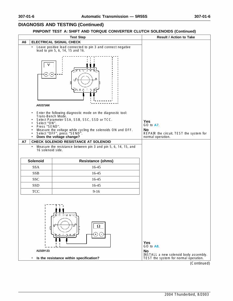
Test Step Result / Action to TakeA6 ELECTRICAL SIGNAL CHECK
• Leave positive lead connected to pin 3 and connect negativelead to pin 5, 6, 14, 15 and 16.
• Enter the following diagnostic mode on the diagnostic tool:Trans-Bench Mode.
• Select Parameter SSA, SSB, SSC, SSD or TCC. Yes• Select ‘‘ON’’. GO to A7.• Press ‘‘SEND’’.• Measure the voltage while cycling the solenoids ON and OFF. No• Select ‘‘OFF’’, press ‘‘SEND’’. REPAIR the circuit. TEST the system for• Does the voltage change? normal operation.
A7 CHECK SOLENOID RESISTANCE AT SOLENOID• Measure the resistance between pin 3 and pin 5, 6, 14, 15, and
16 solenoid side.
Solenoid Resistance (ohms)
SSA 16-45
SSB 16-45
SSC 16-45
SSD 16-45
TCC 9-16
YesGO to A8.NoINSTALL a new solenoid body assembly.
• Is the resistance within specification? TEST the system for normal operation.
(Continued)
2004 Thunderbird, 8/2003

307-01-7 307-01-7Automatic Transmission — 5R55S
DIAGNOSIS AND TESTING (Continued)PINPOINT TEST A: SHIFT AND TORQUE CONVERTER CLUTCH SOLENOIDS (Continued)
Test Step Result / Action to TakeA8 CHECK SOLENOID FOR SHORT TO GROUND
• Measure the resistance between pin 3 and pin 5, 6, 14, 15, and16 solenoid side and ground.
YesINSTALL a new solenoid body assembly.NoREFER to Diagnosis By Symptom in thissection for diagnosis of shift or torque
• Is the resistance less than 5 ohms? converter concerns.
PINPOINT TEST B: TRANSMISSION FLUID TEMPERATURE (TFT) SENSOR
NOTE: Refer to the Transmission Vehicle Harness Connector illustration preceding thesepinpoint tests.
Test Step Result / Action to TakeB1 ELECTRONIC DIAGNOSTICS
• Key in OFF position.• Select PARK.• Check to make sure the transmission harness connector is fully
seated, terminals are fully engaged in connector and in goodcondition before proceeding. Yes• Connect the diagnostic tool. REMAIN in PID/Data Control. GO to B2.• Key in ON position.
• Select Diagnostic Data Link. No• Select PCM. REPEAT procedure to enter PID. If vehicle• Select PID/Data Monitor and Record. did not enter PID, REFER to• Enter the following diagnostic mode on the diagnostic tool: PIDs; thePowertrain Control/Emissions Diagnosis
TFT, TFTV. (PC/ED) manual for diagnosis of PCM and• Does the vehicle enter PID/Data Monitor and Record? NGS.
B2 WARM-UP/COOL-DOWN CYCLE• While monitoring the TFT PIDs, carry out the following test: If Yes
transmission is cold, run transmission to warm it up. If If the TFT PIDs increase as thetransmission is warm, allow transmission to cool down. transmission is warmed or decrease as
• Do the TFT PIDs increase as the transmission is warmed up the transmission is cooled, CLEAR allor decrease as the transmission is cooled or does the TFT DTCs. ROAD TEST to verify if concern isor TFTV drop in and out of range? still present. If concern is still present,
REFER to Diagnosis By Symptom in thissection to diagnose transmissionoverheating.If the TFT or TFTV drop in and out ofrange, INSPECT for intermittent concern inthe internal/external harness, sensor orconnector.NoGO to B3.
B3 ELECTRICAL SIGNAL CHECK• Disconnect: Transmission Harness Connector.• Visually inspect all wires and connectors for damage.
(Continued)
2004 Thunderbird, 8/2003

307-01-8 307-01-8Automatic Transmission — 5R55S
DIAGNOSIS AND TESTING (Continued)PINPOINT TEST B: TRANSMISSION FLUID TEMPERATURE (TFT) SENSOR (Continued)
Test Step Result / Action to TakeB3 ELECTRICAL SIGNAL CHECK (Continued)
• Measure the voltage between pin 2 harness side and ground.
YesGO to B4.NoREPAIR the circuit. TEST the system for
• Is the voltage between 4.5 and 5.0 volts? normal operation.B4 CHECK RESISTANCE OF TFT SENSOR
• Measure the resistance between pin 2 and 12 at the solenoidbody connector.
• Record the resistance.• Resistance should be approximately in the following ranges:
Transmission Fluid Temperature
°C °F Resistance (Ohms)
-40 to -20 -40 to -4 967K - 284K
-19 to -1 -3 - 31 284K - 100K
0 - 20 32 - 68 100K - 37K
21 - 40 69 - 104 37K - 16K
41 - 70 105 - 158 16K - 5K
71 - 90 159 - 194 5K - 2.7K
91 - 110 195 - 230 2.7K - 1.5K YesREFER to Diagnosis By Symptom in this111 - 130 231 - 266 1.5K - 0.8K section to diagnose an overheatingconcern.131 - 150 267 - 302 0.8K - 0.54KNo
• Is the resistance in the range? INSTALL a new solenoid body assembly.
2004 Thunderbird, 8/2003

307-01-9 307-01-9Automatic Transmission — 5R55S
DIAGNOSIS AND TESTING (Continued)PINPOINT TEST C: DIGITAL TRANSMISSION RANGE (TR) SENSOR
NOTE: Refer to the Digital Transmission Range (TR) Sensor Connector illustration and DigitalTransmission Range TR) Sensor Diagnosis Chart preceding these pinpoint tests.
Test Step Result / Action to TakeC1 VERIFY DIAGNOSTIC TROUBLE CODES
• Key in OFF position. Yes• Select PARK. GO to C4.• Carry out on-board diagnostic test. No• Are only DTC codes P0705, P0708 present? GO to C2.
C2 VERIFY DIGITAL TRANSMISSION RANGE SENSOR ALIGNMENT• Key in OFF position.• Select PARK.• Check to make sure the digital TR sensor harness connector is Yesfully seated, terminals are fully engaged in connector and in GO to C3.good condition before proceeding.• Apply the parking brake. No• Select NEUTRAL. ADJUST the digital TR sensor; REFER• Disconnect the shift cable/linkage from the manual lever. toDigital Transmission Range (TR) Sensor• Verify that the TR Sensor Alignment Gauge fits in the in this section. PLACE transmission range
appropriate slots. selector lever into PARK and CLEAR• Is the digital TR sensor correctly adjusted? DTCs. RERUN OBD Tests. GO to C3.
C3 VERIFY SHIFT CABLE/LINKAGE ADJUSTMENT• Place range selector lever in D5. Yes• Connect the shift cable/linkage. GO to C4.• Verify that the shift cable/linkage is correctly adjusted. Refer NotoSelector Lever Cable Adjustment in this section. ADJUST the shift cable/linkage. REFER• Is the shift cable/linkage is correctly adjusted? toSelector Lever Cable Adjustment in this
section. GO to C4.C4 CHECK ELECTRICAL SIGNAL OPERATION
• Select PARK.• Disconnect: Digital TR Sensor.
YesREPAIR as necessary. CLEAR DTCs andCAUTION: Do not pry on connector. This will damage RERUN OBD Tests.the connector and result in a transmission concern.NoPress button and pull out on the digital TR harness connector.If diagnosing a DTC, GO to C5.• Inspect both ends of the connector for damage or pushed out
pins, corrosion, loose wires and missing or damaged seals. If diagnosing a starting concern or a• Is there damage to the connector, pins or harness? backup lamp concern, GO to C10.
C5 CHECK ELECTRICAL SYSTEM OPERATION (DIGITAL TR ANDPCM)• Key in OFF position.• Connect the diagnostic tool.• Connect: Digital TR Sensor.• Key in ON position.• Enter the following diagnostic mode on the diagnostic tool: TR
PIDS TR D, TR V.• Move transmission range selector lever into each gear and stop.• Observe the PIDs, TR D, and TR V (vehicle-dependent) while Yes
wiggling harness, tapping on sensor, or driving the vehicle. Use The problem is not in the digital TR sensorPIDs TR D for DTCs P0705, P1704, and P1705. Use PIDs system. REFER to Diagnosis By SymptomTR V for DTC P0708. in this section for further diagnosis.
• Compare the PIDs to the Digital Transmission Range (TR)NoSensor Diagnosis Chart.If TR D changes when wiggling harness,• Do the PIDs TR D and TR V match the Digitaltapping on the sensor or driving theTransmission Range (TR) Sensor Diagnosis chart, and doesvehicle, the problem may be intermittent.the TR D PID remain steady when the harness is wiggled,
the sensor is tapped on, or the vehicle driven? GO to C6.
(Continued)
2004 Thunderbird, 8/2003

307-01-10 307-01-10Automatic Transmission — 5R55S
DIAGNOSIS AND TESTING (Continued)PINPOINT TEST C: DIGITAL TRANSMISSION RANGE (TR) SENSOR (Continued)
Test Step Result / Action to TakeC6 CHECK DIGITAL TRANSMISSION RANGE SENSOR OPERATION
• Disconnect: Digital TR Sensor. Yes• Connect: TR-E Cable to Transmission Tester. Concern is not in the digital TR sensor.• Connect: TR-E Cable to Digital TR Sensor. GO to C7.• Place the DIGITAL TR Overlay onto Transmission Tester. No• Carry out SENSOR Test as instructed on the digital TR Overlay. INSTALL a new digital TR sensor and• Does the status lamp on the tester TRS-E cable match the ADJUST. REFER toDigital Transmissionselected gear positions? Range (TR) Sensor in this section. CLEAR
DTCs and RERUN OBD Tests.C7 CHECK PCM HARNESS CIRCUITS FOR OPENS
• Key in OFF position.• Disconnect: 150 Pin PTEC Module Connector ‘‘B’’.
Inspect for damaged or pushed out pins, corrosion or loosewires.
• Disconnect: Digital TR Sensor.
CAUTION: Do not pry the connector. This will damagethe connector and result in a transmission concern.Disconnect the digital TR sensor connector.
• Measure the resistance between TR pin 2 harness side andsignal return PCM pin 14 harness side.
• Measure the resistance between PCM pin 22 and TR pin 4harness side.
(Continued)
2004 Thunderbird, 8/2003

307-01-11 307-01-11Automatic Transmission — 5R55S
DIAGNOSIS AND TESTING (Continued)PINPOINT TEST C: DIGITAL TRANSMISSION RANGE (TR) SENSOR (Continued)
Test Step Result / Action to TakeC7 CHECK PCM HARNESS CIRCUITS FOR OPENS (Continued)
• Measure the resistance between PCM pin 18 and TR pin 5harness side.
• Measure the resistance between PCM pin 10 and TR pin 6harness side.
• Measure the resistance between PCM pin 9 and TR pin 3harness side.
YesGO to C8.NoREPAIR the circuits. TEST the system for
• Are the resistances less than 5 ohms? normal operation.
(Continued)
2004 Thunderbird, 8/2003

307-01-12 307-01-12Automatic Transmission — 5R55S
DIAGNOSIS AND TESTING (Continued)PINPOINT TEST C: DIGITAL TRANSMISSION RANGE (TR) SENSOR (Continued)
Test Step Result / Action to TakeC8 CHECK PCM HARNESS CIRCUITS FOR SHORT TO GROUND
OR POWER• Measure the resistance between PCM pin 14 and TR pin 10 and
12 harness side and ground.
• Measure the resistance between pin 22 harness side andground; and pin 14 harness side and ground.
• Measure the resistance between pin 18 harness side andground; and pin 14 harness side and ground.
(Continued)
2004 Thunderbird, 8/2003

307-01-13 307-01-13Automatic Transmission — 5R55S
DIAGNOSIS AND TESTING (Continued)PINPOINT TEST C: DIGITAL TRANSMISSION RANGE (TR) SENSOR (Continued)
Test Step Result / Action to TakeC8 CHECK PCM HARNESS CIRCUITS FOR SHORT TO GROUND
OR POWER (Continued)
• Measure the resistance between pin 10 harness side andground; and pin 14 harness side and ground.
• Measure the resistance between pin 9 harness side and ground;and pin 14 harness side and ground.
YesGO to C9.NoREPAIR the circuits. TEST the system fornormal operation. CLEAR DTCs. RERUN
• Are the resistances greater than 10,000 ohms? OBD Tests.C9 CHECK FOR SHORT BETWEEN TR/PCM INPUT SIGNAL
CIRCUITS• Measure the resistance between pin 9 harness side and pin 22;
pin 18; pin 10 harness side.
(Continued)
2004 Thunderbird, 8/2003

307-01-14 307-01-14Automatic Transmission — 5R55S
DIAGNOSIS AND TESTING (Continued)PINPOINT TEST C: DIGITAL TRANSMISSION RANGE (TR) SENSOR (Continued)
Test Step Result / Action to TakeC9 CHECK FOR SHORT BETWEEN TR/PCM INPUT SIGNAL
CIRCUITS (Continued)
• Measure the resistance between pin 22 harness side and pin 9;pin 18; pin 10 harness side.
• Measure the resistance between pin 18 harness side and pin22; pin 9; pin 10 harness side.
• Measure the resistance between pin 10 harness side and pin22; pin 18; pin 9 harness side.
YesINSTALL a new PCM. TEST the systemfor normal operation.NoREPAIR the circuit. TEST the system for
• Are the resistances greater than 10,000 ohms? normal operation.
(Continued)
2004 Thunderbird, 8/2003

307-01-15 307-01-15Automatic Transmission — 5R55S
DIAGNOSIS AND TESTING (Continued)PINPOINT TEST C: DIGITAL TRANSMISSION RANGE (TR) SENSOR (Continued)
Test Step Result / Action to TakeC10 CHECK THE NON-PCM INTERNAL CIRCUITS OF SENSOR
• Connect: TRS-E Cable to Transmission. Yes• Connect: TRS-E Cable to Digital TR Sensor. Concern is not in the digital TR sensor.• Place the Digital TR Overlay onto Transmission Tester. For start system concerns, REFER• Carry out Switch Test as instructed on the digital TR Overlay. toSection 303-04 or Section 303-04. For• Does the status lamp on the tester indicate RED for the backup lamp concerns, REFER toSection
correct gear position? 417-01.NoINSTALL a new digital TR sensor andADJUST; REFER toDigital TransmissionRange (TR) Sensor in this section. CLEARDTCs and RERUN OBD Tests.
PINPOINT TEST D: PRESSURE CONTROL (PC) SOLENOIDS (PCA, PCB, PCC)
NOTE: Refer to the Transmission Vehicle Harness Connector illustration preceding thesepinpoint tests.
NOTE: Read and record all DTCs. All digital TR Sensor and VSS DTCs must be repairedbefore entering Output State Control (OSC).
Test Step Result / Action to TakeD1 ELECTRONIC DIAGNOSTICS
• Key in OFF position.• Select PARK.• Check to make sure the transmission harness connector is fully
seated, terminals are fully engaged in the connector and in goodcondition before proceeding.
• Install 300 psi pressure gauges into Line and PC C tap.• Connect the diagnostic tool.• Key in ON position.• Enter the following diagnostic mode on the diagnostic tool:
Diagnostic Data Link. Yes• Enter the following diagnostic mode on the diagnostic tool: PCM. REMAIN in Trans-Bench Mode. GO to D2.• Enter the following diagnostic mode on the diagnostic tool:Active Command Modes. No
• Enter the following diagnostic mode on the diagnostic tool: REPEAT procedure to enter Trans-BenchOutput State Control (OSC). Mode. If vehicle did not enter OSC,
• Enter the following diagnostic mode on the diagnostic tool: REFER toPowertrain Control/EmissionsTrans-Bench Mode. Diagnosis (PC/ED) manual for diagnosis of
• Does the vehicle enter the Trans-Bench Mode? PCM or NGS.D2 SOLENOID FUNCTIONAL TEST
• Monitor pressure gauges.• Enter the following diagnostic mode on the diagnostic tool:
Parameter; PCx.• NOTE: Make sure that the solenoids not being tested are off or
at zero.Select PC A, PC B, or PC C.
• Select value - 15, 30, 45, 60, 70 or 90 psi.• Press ‘‘SEND’’.• Select another value ‘‘0-90 psi’’.• Press ‘‘SEND’’.• Enter the following diagnostic mode on the diagnostic tool: XXX.• Press ‘‘SEND’’.• For PC A and PC B: Does the pressure reading for A or B Yesfollow the commanded pressure, (actual A and B pressures CLEAR DTCs.will be higher than the commanded pressure)? For PC C:
Does the pressure reading match the commanded Nopressure?‘‘ GO to D3.
D3 CHECK FOR BATTERY VOLTAGE• Disconnect: Transmission Harness Connector.• Visually inspect all wires and connectors for damage.• Key in ON position.
(Continued)
2004 Thunderbird, 8/2003

307-01-16 307-01-16Automatic Transmission — 5R55S
DIAGNOSIS AND TESTING (Continued)PINPOINT TEST D: PRESSURE CONTROL (PC) SOLENOIDS (PCA, PCB, PCC) (Continued)
Test Step Result / Action to TakeD3 CHECK FOR BATTERY VOLTAGE (Continued)
• Measure the voltage between pin 3 harness side and ground.
YesGO to D4.NoREPAIR the circuit. TEST the system for
• Is the voltage greater than 10 volts? normal operation.D4 ELECTRICAL SIGNAL CHECK
• Leave positive lead connected pin 3 and connect negative leadto pins 1, 4 and 11 harness side.
• Activate solenoids (ON and OFF) while monitoring the voltagereading.
• Enter the following diagnostic mode on the diagnostic tool:Trans-Bench Mode.
• Enter the following diagnostic mode on the diagnostic tool:Parameter; PCx.
• Select a value ’’0-90 psi‘‘.• Press ’’SEND‘‘. Yes• Select another value ’’0-90 psi‘‘. GO to D5.• Press ’’SEND‘‘.• Enter the following diagnostic mode on the diagnostic tool: XXX. No• Press ’’SEND‘‘. CHECK for open or short circuit in• Does the voltage and solenoid state change? harness or PCM.
(Continued)
2004 Thunderbird, 8/2003

307-01-17 307-01-17Automatic Transmission — 5R55S
DIAGNOSIS AND TESTING (Continued)PINPOINT TEST D: PRESSURE CONTROL (PC) SOLENOIDS (PCA, PCB, PCC) (Continued)
Test Step Result / Action to TakeD5 CHECK SOLENOID RESISTANCE AT SOLENOID
• Measure and record the resistance between PC solenoid pin 3and pins 1, 4, and 11. Resistance should be between 3.3 and7.5 ohms.
YesGO to D6.No
• Is the resistance within specifications? INSTALL a new solenoid body assembly.D6 CHECK SOLENOID FOR SHORT TO GROUND
• Measure and record the resistance between the PC solenoidpins 1, 4, 11, and ground solenoid side.
YesINSTALL a new solenoid body assembly.TEST the system for normal operation.NoREFER to Diagnosis By Symptom in thissection for diagnosis of pressure concerns.
• Is the resistance less than 10,000 ohms? TEST the system for normal operation.
PINPOINT TEST E: TURBINE SHAFT SPEED (TSS), INTERMEDIATE SHAFT SPEED (ISS), AND OUTPUTSHAFT SPEED (OSS) SENSORS
NOTE: Refer to the turbine shaft speed (TSS), intermediate shaft speed (ISS), and output shaftspeed (OSS) sensor connector illustrations preceding these pinpoint tests.
Test Step Result / Action to TakeE1 ELECTRONIC DIAGNOSTICS
• Check to make sure the transmission harness connectors arefully seated, terminals are fully engaged in connector and ingood condition before proceeding. Yes• Connect the diagnostic tool. REMAIN in PID/Data. GO to E2.• Key in ON position.
• Enter the following diagnostic mode on the diagnostic tool: NoDiagnostic Data Link. REPEAT procedure to ENTER PID. If
• Enter the following diagnostic mode on the diagnostic tool: PCM. vehicle did not enter PID, REFER to• Select PID/Data Monitor and Record. thePowertrain Control/Emissions Diagnosis• Select the following PIDs: TSS, ISS, or OSS. (PC/ED) manual for diagnosis of PCM or• Does vehicle enter PID/Data Monitor and Record? NGS.
(Continued)
2004 Thunderbird, 8/2003

307-01-18 307-01-18Automatic Transmission — 5R55S
DIAGNOSIS AND TESTING (Continued)PINPOINT TEST E: TURBINE SHAFT SPEED (TSS), INTERMEDIATE SHAFT SPEED (ISS), AND OUTPUT
SHAFT SPEED (OSS) SENSORS (Continued)
Test Step Result / Action to TakeE2 DRIVE CYCLE TEST
• While monitoring the appropriate sensor PID, drive the vehicle Yesso that the transmission upshifts and downshifts through all GO to E3.gears. No• Does the TSS, ISS, or OSS Speed PID increase and If the TSS, ISS, or OSS Speed PID doesdecrease with engine and vehicle speed? not increase and decrease with engine
and vehicle speed, INSPECT for open orshort in vehicle harness, sensor, a PCMconcern, or internal hardware concern. GOto E4.
E3 DRIVE CYCLE TEST ERRATIC• While monitoring the appropriate sensor PID, drive the vehicle Yes
so that the transmission upshifts and downshifts through all If the sensor signal is erratic, INSPECT forgears. intermittent concern in the harness,
• Is the TSS, ISS, or OSS Speed PID signal erratic (drop to sensor, or connector. GO to E4.zero or near zero and return to normal operation)? No
CLEAR all DTCs. Rerun OBD.E4 CHECK PCM HARNESS CIRCUITS FOR OPENS
• Key in OFF position.• Disconnect: 150 Pin PTEC Module Connector ’’B‘‘.
Inspect for damaged or pushed out pins, corrosion or loosewires.
• For OSS, measure the resistance between pin 17 and theappropriate sensor connector pin 2 harness side.
• For ISS, measure the resistance between pin 17 and theappropriate sensor connector pin 2 harness side.
(Continued)
2004 Thunderbird, 8/2003

307-01-19 307-01-19Automatic Transmission — 5R55S
DIAGNOSIS AND TESTING (Continued)PINPOINT TEST E: TURBINE SHAFT SPEED (TSS), INTERMEDIATE SHAFT SPEED (ISS), AND OUTPUT
SHAFT SPEED (OSS) SENSORS (Continued)
Test Step Result / Action to TakeE4 CHECK PCM HARNESS CIRCUITS FOR OPENS (Continued)
• For TSS, measure the resistance between pin 17 and theappropriate sensor connector pin 2 harness side.
• For ISS, measure the resistance between pin 21 and theappropriate sensor connector pin 1 harness side.
• For TSS, measure the resistance between pin 27 and theappropriate sensor connector pin 1 harness side.
(Continued)
2004 Thunderbird, 8/2003

307-01-20 307-01-20Automatic Transmission — 5R55S
DIAGNOSIS AND TESTING (Continued)PINPOINT TEST E: TURBINE SHAFT SPEED (TSS), INTERMEDIATE SHAFT SPEED (ISS), AND OUTPUT
SHAFT SPEED (OSS) SENSORS (Continued)
Test Step Result / Action to TakeE4 CHECK PCM HARNESS CIRCUITS FOR OPENS (Continued)
• For OSS, measure the resistance between pin 26 and theappropriate sensor connector pin 1 harness side.
YesGO to E5.NoREPAIR the circuit. TEST the system for
• Are all resistances less than 5 ohms? normal operation.E5 CHECK PCM HARNESS CIRCUITS FOR SHORT TO GROUND
• For OSS, measure the resistance between pin 26 and sensorconnector pin 1 harness side and ground.
• For ISS, measure the resistance between PCM pin 21 andsensor connector pin 1 harness side and ground.
(Continued)
2004 Thunderbird, 8/2003
307-01-21 307-01-21Automatic Transmission — 5R55S
DIAGNOSIS AND TESTING (Continued)PINPOINT TEST E: TURBINE SHAFT SPEED (TSS), INTERMEDIATE SHAFT SPEED (ISS), AND OUTPUT
SHAFT SPEED (OSS) SENSORS (Continued)
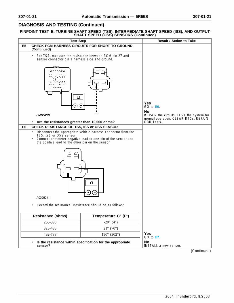
Test Step Result / Action to TakeE5 CHECK PCM HARNESS CIRCUITS FOR SHORT TO GROUND
(Continued)
• For TSS, measure the resistance between PCM pin 27 andsensor connector pin 1 harness side and ground.
YesGO to E6.NoREPAIR the circuits. TEST the system fornormal operation. CLEAR DTCs. RERUN
• Are the resistances greater than 10,000 ohms? OBD Tests.E6 CHECK RESISTANCE OF TSS, ISS or OSS SENSOR
• Disconnect the appropriate vehicle harness connector from theTSS, ISS or OSS sensor.
• Connect ohmmeter negative lead to one pin of the sensor andthe positive lead to the other pin on the sensor.
• Record the resistance. Resistance should be as follows:
Resistance (ohms) Temperature C° (F°)266-390 -20° (4°)
325-485 21° (70°)
Yes492-738 150° (302°)GO to E7.
• Is the resistance within specification for the appropriate Nosensor? INSTALL a new sensor.
(Continued)
2004 Thunderbird, 8/2003

307-01-22 307-01-22Automatic Transmission — 5R55S
DIAGNOSIS AND TESTING (Continued)PINPOINT TEST E: TURBINE SHAFT SPEED (TSS), INTERMEDIATE SHAFT SPEED (ISS), AND OUTPUT
SHAFT SPEED (OSS) SENSORS (Continued)
Test Step Result / Action to TakeE7 CHECK SENSORS FOR SHORT TO GROUND
• Measure the resistance between pin 1 and 2 of each sensor andground.
YesINSTALL a new sensor.NoREFER to Diagnosis By Symptom fordiagnosis of shift or torque converter
• Is the resistance less than 10,000 ohms? concerns in this section.
PINPOINT TEST F: SOLENOID MECHANICAL FAILURE
NOTE: Repair all other DTCs before repairing the following DTCs: P1714, P1715, P1716,P1717, P1740.
Test Step Result / Action to TakeF1 ELECTRONIC DIAGNOSIS
• Connect the diagnostic tool. Yes• Select PARK. REPAIR the DTCs for TFT or shift• Key in ON position. solenoids first. CLEAR DTCs and CARRY• Carry out KOEO test until continuous DTCs have been OUT transmission Drive Cycle test.
displayed. RERUN Quick Test.• If any of the following DTCs are present, continue with this test: NoP1714, P1715, P1716, P1717, P1740. INSTALL a new solenoid and/or body.• Are other DTCs present for TFT or shift solenoids? REFER to the Diagnostic Trouble Code
Charts for code description. GO to F2.F2 TRANSMISSION DRIVE CYCLE TEST
• Carry out transmission drive cycle test. Refer to Transmission YesDrive Cycle Test in this section. GO to F3.
• Does the vehicle upshift and downshift OK? NoREFER to Diagnosis By Symptom in thissection to diagnose shift concerns.
F3 RETRIEVE DTCS• Connect the diagnostic tool. Yes• Select PARK. INSTALL a new PCM. ROAD TEST and• Key in ON position. RERUN Quick Test.• Carry out KOEO test until continuous DTCs have been Nodisplayed. Testing completed. If a concern still exists,• Are DTCs P1714, P1715, P1716, P1717, P1740 still present? REFER to Diagnosis By Symptom in this
section for concern diagnosis.
PINPOINT TEST G: REVERSE PRESSURE SWITCH
NOTE: Refer to the Reverse Pressure (RP) Switch Diagnosis Chart preceding these pinpointtests.
Test Step Result / Action to TakeG1 ELECTRONIC DIAGNOSIS
• Key in OFF position.• Select PARK.
(Continued)
2004 Thunderbird, 8/2003

307-01-23 307-01-23Automatic Transmission — 5R55S
DIAGNOSIS AND TESTING (Continued)PINPOINT TEST G: REVERSE PRESSURE SWITCH (Continued)
Test Step Result / Action to TakeG1 ELECTRONIC DIAGNOSIS (Continued)
• Check to make sure that the transmission harnesses is fullyseated, the terminals are fully engaged in the connector, and theterminals are in good condition.
• Connect the diagnostic tool. Yes• Key in ON position. REMAIN in PID/DATA control. GO to G2.• Select Diagnostic Data Link.• Select PCM. No• Select PID DATA Monitor and record. REPEAT the procedure. If vehicle did not• Enter the following diagnostic mode on the diagnostic tool: PIDs: enter PID, REFER to the Powertrain
RPS, FFG RPS. Control/Emissions Diagnosis (PC/ED)• Does the vehicle enter PID/DATA Monitor and record? manual for PCM and NGS.
G2 ELECTRICAL SIGNAL CHECK• Carry out Transmission Drive Cycle Test and monitor line Yes
pressure and PIDs: RPS, FFG RPS. RP switch is OK. REFER to Diagnosis By• Do the PIDs: RPS, FFG RPS match the chart for a given Symptom in this section.
gear? NoGO to G3.
G3 CHECK HARNESS FOR OPENS• Key in OFF position.• Disconnect: 150 Pin PTEC Module Connector ’’B‘‘.• Disconnect: Transmission Connector.• Measure the resistance between PCM pin 30 and pin 13
harness side.
• Measure the resistance between PCM pin 17 and pin 12harness side.
YesGO to G4.NoREPAIR the circuit. CLEAR DTCs.
• Are the resistances less than 5 ohms? RERUN OBD tests.
(Continued)
2004 Thunderbird, 8/2003

307-01-24 307-01-24Automatic Transmission — 5R55S
DIAGNOSIS AND TESTING (Continued)PINPOINT TEST G: REVERSE PRESSURE SWITCH (Continued)
Test Step Result / Action to TakeG4 CHECK CIRCUIT FOR SHORT TO GROUND OR POWER
• Measure the resistance between PCM pin 30 and pin 17harness side and ground.
YesINSTALL a new reverse pressure switch.TEST the system for normal operation.NoREPAIR the circuit. CLEAR the DTCs.RERUN OBD test. TEST the system for
• Is the resistance less than 10,000 ohms? normal operation.
2004 Thunderbird, 8/2003