PIM, MAXA-MI$ER UERV Models V4074A40 & VR122A40 … · VII - In st al la t ion ... UNI TARY EN ERGY...
16
PAGE 1 I - Shipping And Packing List Package 1 of 2 contains: 1 - Energy Recovery Ventilator Assembly 2 - Outdoor Fresh Air Hood w/ Filter 2 - Outdoor Exhaust Hood w/ Barometric Dampers Package 2 of 2 contains: 1 - Platform Support Rail 2 - Side Filler Panels 1 - Middle Divider Panel 1 - Bag Assembly 2 - Roll of ¾" x 1 ¼" gasket 20 - #14 Screws 30 - #10 x ½" Gold Screws 10 - #10 x ½" Self Tapping Screws 12 - #10 x 1 ½" Self Tapping Screws 1 - Installation Instructions II - Shipping Damage Check unit for shipping damage. Receiving party should contact last carrier immediately if shipping damage is found. III - General These instructions are intended as a general guide and do not supersede local codes in any way. Authorities having jurisdiction should be consulted before installation. IV - Requirements When installed, the unit must be electrically wired and grounded in accordance with local codes or, in absence of local codes, with the current National Electric Code, ANSI/NFPA No. 70. V - Application Unitary Energy Recovery Ventilator (UERV) are used with Millennium rooftop units. These wheels conserve energy by mixing warmer air with cooler air in the following manner: Recovery Wheel Mode The Recovery Wheel mode is accomplished by two blowers providing continuous exhaust of stale indoor air and replacement by equal amount of outdoor air. Energy recovery is achieved by slowly rotating the energy recovery wheel within the cassette frame work. In winter, the UERV adsorbs heat and moisture from the exhaust air stream during one half of a complete rotation and gives them back to the cold, drier intake air supply during the other half rotation. In summer, the process is automatically reversed. Heat and moisture are absorbed from incoming fresh air supply and transferred to the exhaust air stream. This process allows outdoor air ventilation rates to be increased by factors of three or more without an increase in size or additional energy penalty of heating or air conditioning systems. Economizer Mode When an UERV is used on a Millennium rooftop unit with an economizer, the stop-start-jog option is necessary. When the rooftop unit determines that conditions are correct for economizer mode, the UERV will disable the rotation of the enthalpy wheel. The exhaust blowers in the UERV will continue to run. The maximum air volume of the rooftop unit blower exceeds the maximum capacity of the power exhaust blowers in the UERV. The wheel will remain off until a preset timer will rotate the wheel for a short period of time periodically to prevent contamination of the wheel. This will continue until the rooftop unit shuts the side hood dampers. Energy recovery COMPONENT certified to the ARI Air-to-Air Energy Recovery Ventilation Equipment Certification Program in accordance with ARI Standard 1060-2000 . Actual performance in packaged equipment may vary. ETL Certified per UL 1995 and CSA 22.2 INSTALLATION INSTRUCTIONS MAXA-MI$ER™ UNITARY ENERGY RECOVERY VENTILATOR MODELS VR074A40 & VR122A40 (STATIONARY) Electric shock hazard. Can cause injury or death. Before attempting to perform any service or maintenance, turn the electrical power to unit OFF at disconnect switch(es). Unit may have multiple power supplies. WARNING 035-20262-000-A-0205 / R74A-26YDW
Transcript of PIM, MAXA-MI$ER UERV Models V4074A40 & VR122A40 … · VII - In st al la t ion ... UNI TARY EN ERGY...
PAGE 1
I - Ship ping And Pack ing List
Package 1 of 2 contains:
1 - Energy Recovery Ventilator Assembly2 - Outdoor Fresh Air Hood w/ Filter2 - Outdoor Exhaust Hood w/ Barometric Dampers
Package 2 of 2 contains:
1 - Platform Support Rail2 - Side Filler Panels1 - Middle Divider Panel1 - Bag Assembly
2 - Roll of ¾" x 1 ¼" gasket 20 - #14 Screws 30 - #10 x ½" Gold Screws 10 - #10 x ½" Self Tapping Screws12 - #10 x 1 ½" Self Tapping Screws 1 - Installation Instructions
II - Ship ping Dam age
Check unit for shipping damage. Receiving party shouldcontact last carrier immediately if shipping damage isfound.
III - Gen eral
These instructions are intended as a general guide and donot supersede local codes in any way. Authorities havingjurisdiction should be consulted before installation.
IV - Re quire ments
When installed, the unit must be electrically wired andgrounded in accordance with local codes or, in absence oflocal codes, with the current National Electric Code,ANSI/NFPA No. 70.
V - Ap pli ca tion
Unitary Energy Recovery Ventilator (UERV) are used withMillennium rooftop units. These wheels conserveenergy by mixing warmer air with cooler air in the followingmanner:
Re cov ery Wheel Mode
The Recovery Wheel mode is accomplished by twoblowers providing continuous exhaust of stale indoor airand replacement by equal amount of outdoor air.Energy recovery is achieved by slowly rotating theenergy recovery wheel within the cassette frame work.In winter, the UERV adsorbs heat and moisture from theexhaust air stream during one half of a complete rotation and gives them back to the cold, drier intake air supplyduring the other half rotation. In summer, the process isautomatically reversed. Heat and moisture are
absorbed from incoming fresh air supply and transferred to the exhaust air stream. This process allows outdoorair ventilation rates to be increased by factors of three ormore without an increase in size or additional energypenalty of heating or air conditioning systems.
Economizer Mode
When an UERV is used on a Millennium rooftop unit with an economizer, the stop-start-jog option is necessary.When the rooftop unit determines that conditions arecorrect for economizer mode, the UERV will disable therotation of the enthalpy wheel. The exhaust blowers inthe UERV will continue to run. The maximum air volumeof the rooftop unit blower exceeds the maximumcapacity of the power exhaust blowers in the UERV. The wheel will remain off until a preset timer will rotate thewheel for a short period of time periodically to preventcontamination of the wheel. This will continue until therooftop unit shuts the side hood dampers.
Energy recovery COMPONENT certifiedto the ARI Air-to-Air Energy RecoveryVentilation Equipment CertificationProgram in accordance w ith ARIStandard 1060-2000 . Actual performance in packaged equipment may vary.
ETL Certified per UL 1995 and CSA 22.2
INSTALLATIONINSTRUCTIONS
MAXA-MI$ER™UNI TARY EN ERGY RE COV ERY VEN TI LA TOR
MODELS VR074A40 & VR122A40 (STATIONARY)
Electric shock hazard. Can cause injury or death. Before attempting to performany service or maintenance, turn theelectrical power to unit OFF atdisconnect switch(es). Unit may havemultiple power supplies.
WARNING
035-20262-000-A-0205 / R74A-26YDW
VI - Rig ging Unit For Lift ing
1- Maximum weight of unit is —- 3000 Lbs. (Crated)
2- Remove crating. Then open access panel to retrievebag assembly. Replace access panel.
3- All panels must be in place for rigging.
4- Lifting lugs are supplied on the unit baserail.
VII - In stal la tion
1- Disconnect all power to the rooftop unit.
2- Remove the rooftop unit’s return air access panels onthe end of the unit. Also, remove any hoods or powerexhaust equipment on the end of the rooftop unit.Discard the removed items.
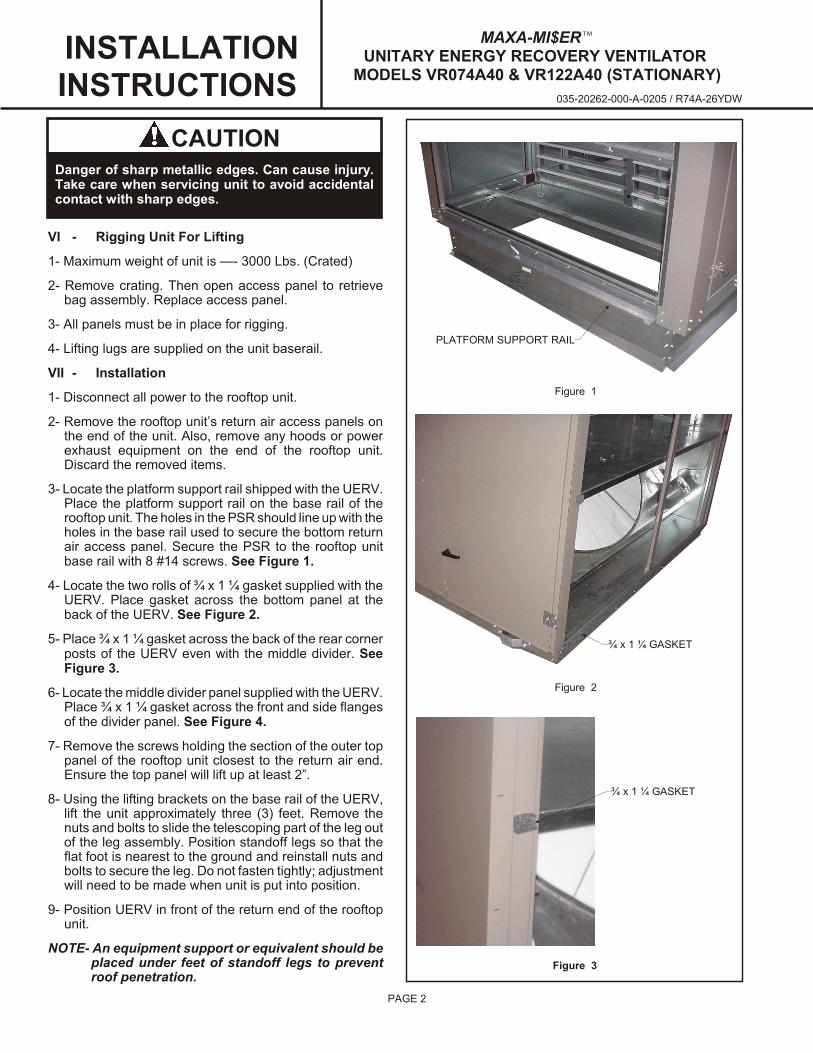
3- Locate the platform support rail shipped with the UERV.Place the platform support rail on the base rail of therooftop unit. The holes in the PSR should line up with the holes in the base rail used to secure the bottom returnair access panel. Secure the PSR to the rooftop unitbase rail with 8 #14 screws. See Figure 1.
4- Locate the two rolls of ¾ x 1 ¼ gasket supplied with theUERV. Place gasket across the bottom panel at theback of the UERV. See Figure 2.
5- Place ¾ x 1 ¼ gasket across the back of the rear cornerposts of the UERV even with the middle divider. SeeFigure 3.
6- Locate the middle divider panel supplied with the UERV. Place ¾ x 1 ¼ gasket across the front and side flangesof the divider panel. See Figure 4.
7- Remove the screws holding the section of the outer toppanel of the rooftop unit closest to the return air end.Ensure the top panel will lift up at least 2”.
8- Using the lifting brackets on the base rail of the UERV,lift the unit approximately three (3) feet. Remove thenuts and bolts to slide the telescoping part of the leg outof the leg assembly. Position standoff legs so that theflat foot is nearest to the ground and reinstall nuts andbolts to secure the leg. Do not fasten tightly; adjustmentwill need to be made when unit is put into position.
9- Position UERV in front of the return end of the rooftopunit.
NOTE- An equipment support or equivalent should beplaced under feet of standoff legs to preventroof penetration.
PAGE 2
INSTALLATIONINSTRUCTIONS
Figure 1
Figure 2
Figure 3
CAUTIONDanger of sharp metallic edges. Can cause injury.Take care when servicing unit to avoid accidentalcontact with sharp edges.
¾ x 1 ¼ GASKET
¾ x 1 ¼ GASKET
PLATFORM SUPPORT RAIL
035-20262-000-A-0205 / R74A-26YDW
MAXA-MI$ER™UNI TARY EN ERGY RE COV ERY VEN TI LA TOR
MODELS VR074A40 & VR122A40 (STATIONARY)

PAGE 3
10- Lower UERV onto PSR. The rear base rail of the UERV should sit onto the flange of the PSR that extends outhorizontally from the rooftop unit base rail. See Figure5.
11- With the UERV in place, adjust the standoff legs tolevel and support the UERV against the rooftop unit.Tighten the nuts and bolts securely. See Figure 6.
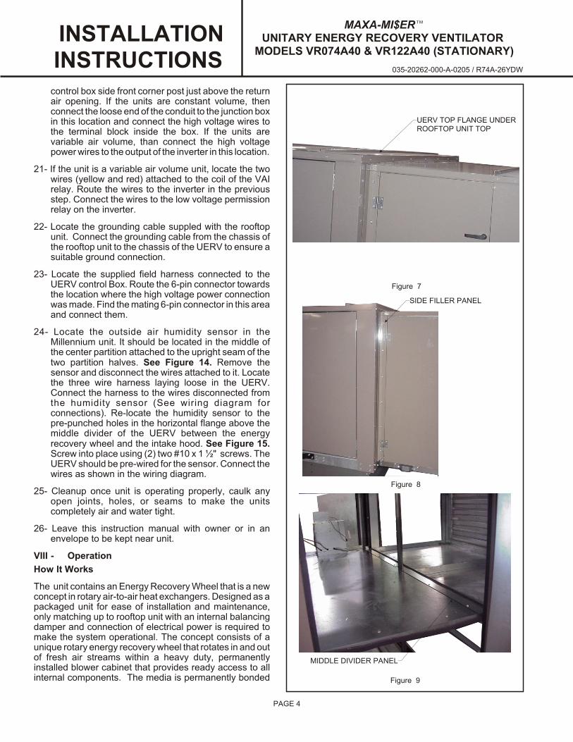
12- Place UERV top flange under the outer top panel of therooftop unit. Secure the rooftop unit top panel with theexisting screws. If UERV is not centered on the returnair end of the rooftop unit, it may be necessary to usethe provided #10 x ½ self-tapping screws to secure top panel through top flange of the UERV. See Figure 7.
13- Loosen the screws securing the side filler panels to theside of the UERV. Adjust the position of the side fillerpanels so they are flush with the corner posts of therooftop unit. Tighten the screws securing the side fillerpanels to the UERV. See Figure 8.
14- Locate the supplied #14 x ¾ self-tapping screws.Secure the side filler panels to the corner posts of therooftop unit with these screws. See Figure 8.
15- Locate the supplied middle divider filler panel. Frominside the rooftop unit, place the middle divider fillerpanel on top of the UERV middle deck and secure with#10 x ½ screws. Center notch of the filler panel shouldfit around middle post of UERV. Ensure that the gasket installed on the filler panel earlier fills the gapsbetween the UERV and rooftop unit divider decks. Ifnot, apply more gasket. See Figure 9.
16- Locate the supplied intake hoods (2). Slide the topflange of the hood under the top panel of the UERV see figure 10. Secure the bottom and sides of the hood tothe UERV using (5) #10 x 1 ½ “ screws. Repeat for theother hood. See Figure 11.
17- Locate the supplied exhaust hoods (2). Line up hood tothe 10 holes on the lower front door panel of the UERV. Secure hood using (10) #10 x ½” screws. See Figure12.
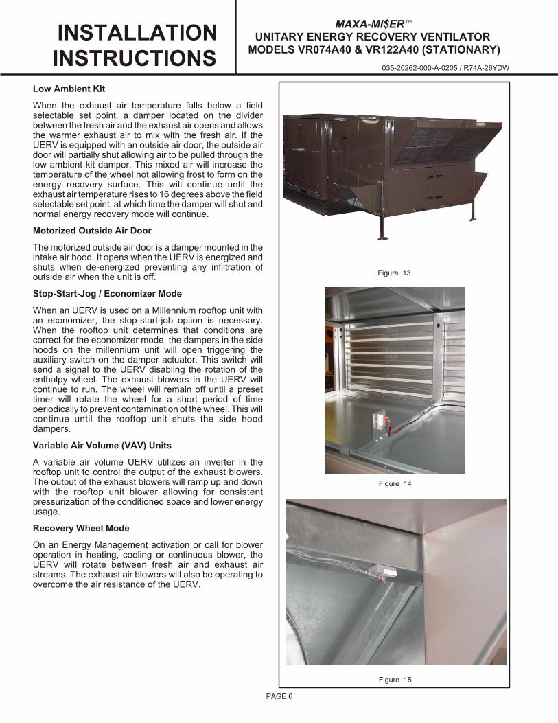
18- Seal, if required, along face (top and sides) of UERVunit where it meets the rooftop unit to ensure there isno air leakage. Final assembly should resembleFigure 13.
19- All electrical connections must conform to any localcodes and current National Electric Codes (NEC) andCanadian Electric Codes (CEC). Refer closely to unitwiring diagram in unit and/or in these instructions forproper wiring connections. Refer to the unit nameplate for minimum circuit ampacity and maximumovercurrent protection size. Electrical data is listed onunit rating plate and motor nameplates.
20- Locate the loose end of the conduit containing the highvoltage wiring connected to the fuse blocks in theUERV control box. Route the conduit towards the
INSTALLATIONINSTRUCTIONS
Figure 5
Figure 6
Figure 4
¾ x 1 ¼ GASKET
035-20262-000-A-0205 / R74A-26YDW
MAXA-MI$ER™UNI TARY EN ERGY RE COV ERY VEN TI LA TOR
MODELS VR074A40 & VR122A40 (STATIONARY)
PAGE 4
control box side front corner post just above the returnair opening. If the units are constant volume, thenconnect the loose end of the conduit to the junction box in this location and connect the high voltage wires tothe terminal block inside the box. If the units arevariable air volume, than connect the high voltagepower wires to the output of the inverter in this location.
21- If the unit is a variable air volume unit, locate the twowires (yellow and red) attached to the coil of the VAIrelay. Route the wires to the inverter in the previousstep. Connect the wires to the low voltage permissionrelay on the inverter.
22- Locate the grounding cable suppled with the rooftopunit. Connect the grounding cable from the chassis ofthe rooftop unit to the chassis of the UERV to ensure asuitable ground connection.
23- Locate the supplied field harness connected to theUERV control Box. Route the 6-pin connector towardsthe location where the high voltage power connectionwas made. Find the mating 6-pin connector in this area and connect them.
24- Locate the outside air humidity sensor in theMillennium unit. It should be located in the middle ofthe center partition attached to the upright seam of thetwo partition halves. See Figure 14. Remove thesensor and disconnect the wires attached to it. Locatethe three wire harness laying loose in the UERV.Connect the harness to the wires disconnected fromthe humidity sensor (See wiring diagram forconnections). Re-locate the humidity sensor to thepre-punched holes in the horizontal flange above themiddle divider of the UERV between the energyrecovery wheel and the intake hood. See Figure 15.Screw into place using (2) two #10 x 1 ½" screws. TheUERV should be pre-wired for the sensor. Connect the wires as shown in the wiring diagram.
25- Cleanup once unit is operating properly, caulk anyopen joints, holes, or seams to make the unitscompletely air and water tight.
26- Leave this instruction manual with owner or in anenvelope to be kept near unit.
VIII - Op er a tion
How It Works
The unit contains an Energy Recovery Wheel that is a newconcept in rotary air-to-air heat exchangers. Designed as a packaged unit for ease of installation and maintenance,only matching up to rooftop unit with an internal balancingdamper and connection of electrical power is required tomake the system operational. The concept consists of aunique rotary energy recovery wheel that rotates in and out of fresh air streams within a heavy duty, permanentlyinstalled blower cabinet that provides ready access to allinternal components. The media is permanently bonded
MAXA-MI$ER™UNI TARY EN ERGY RE COV ERY VEN TI LA TOR
MOD ELS VR074A40 & VR122A40 (STA TION ARY) INSTALLATIONINSTRUCTIONS
Figure 7
Figure 8
Figure 9
SIDE FILLER PANEL
MIDDLE DIVIDER PANEL
UERV TOP FLANGE UNDERROOFTOP UNIT TOP
035-20262-000-A-0205 / R74A-26YDW

PAGE 5
with a dry desiccant coating for total enthalpy recovery.The wheel is belt driven by one motor and drive belt.
When slowly rotating through counter flowing exhaust andfresh air streams the UERV adsorbs sensible heat andlatent heat from the warmer air stream and transfer thistotal energy to the cooler air stream during the second halfof its rotating cycle. Rotating between 50-60 revolutionsper minute, the wheel provides constant flow of energyfrom warmer to cooler air stream. The large energytransfer surface and laminar flow through the wheelcauses this constant flow of recovered energy torepresent up to 85% of the difference in total energycontained within the two air streams.
Sensible and latent heat are the two components of totalheat. Sensible heat is energy contained in dry air and latent heat is the energy contained within the moisture of the air.The latent heat load from the outdoor fresh air on an airconditioning system can often be two to three times that ofthe sensible heat load and in the winter it is a significantpart of a humidification heat load.
During both the summer and winter, the UERV transfersmoisture entirely in the vapor phase. This eliminates wetsurfaces that retain dust and promote fungal growth as well as the need for a condensate pan and drain to carry water.
Because it is constantly rotating when in the air stream, theUERV is always being cleared by air, first in one directionthen the other. Because it is always dry, dust or otherparticles impinging on the surface during one half cycle,are readily removed during the next half cycle.
Optional Low Ambient kit is appropriate for climates withl imi ted HVAC system operat ion when outdoortemperatures are below 15oF.
The frost threshold is the outdoor temperature at whichfrost will begin to form on the UERV wheel. For energyrecovery ventilators, the frost threshold is typically below10oF. Frost threshold is dependent on indoor temperatureand humidity. The table shows how the frost thresholdtemperatures vary depending on indoor conditions.
FROST THRESH OLD TEM PERA TURE
IN DOOR RH AT70oF
FROST THRESH OLDTEM PERA TURE
20% 0oF
30% 5oF
40% 10oF
Because Unitary Energy Recovery Ventilators have a lowfrost threshold, frost control options are not necessary inmany climates. Where outdoor temperatures may dropbelow the frost threshold during the UERV operationalhours, a frost control option is available.
INSTALLATIONINSTRUCTIONS
Figure 10
Figure 12
Figure 11
INTAKE HOOD TOPUNDER UERV TOP
INTAKE HOOD
EXHAUST HOOD
MAXA-MI$ER™UNI TARY EN ERGY RE COV ERY VEN TI LA TOR
MODELS VR074A40 & VR122A40 (STATIONARY)
035-20262-000-A-0205 / R74A-26YDW
Low Am bi ent Kit
When the exhaust air temperature falls below a fieldselectable set point, a damper located on the dividerbetween the fresh air and the exhaust air opens and allowsthe warmer exhaust air to mix with the fresh air. If theUERV is equipped with an outside air door, the outside airdoor will partially shut allowing air to be pulled through thelow ambient kit damper. This mixed air will increase thetemperature of the wheel not allowing frost to form on theenergy recovery surface. This will continue until theexhaust air temperature rises to 16 degrees above the field selectable set point, at which time the damper will shut andnormal energy recovery mode will continue.
Mo tor ized Out side Air Door
The motorized outside air door is a damper mounted in theintake air hood. It opens when the UERV is energized andshuts when de-energized preventing any infiltration ofoutside air when the unit is off.
Stop-Start-Jog / Economizer Mode
When an UERV is used on a Millennium rooftop unit withan economizer, the stop-start-job option is necessary.When the rooftop unit determines that conditions arecorrect for the economizer mode, the dampers in the sidehoods on the millennium unit will open triggering theauxiliary switch on the damper actuator. This switch willsend a signal to the UERV disabling the rotation of theenthalpy wheel. The exhaust blowers in the UERV willcontinue to run. The wheel will remain off until a presettimer will rotate the wheel for a short period of timeperiodically to prevent contamination of the wheel. This will continue until the rooftop unit shuts the side hooddampers.
Vari able Air Vol ume (VAV) Units
A variable air volume UERV utilizes an inverter in therooftop unit to control the output of the exhaust blowers.The output of the exhaust blowers will ramp up and downwith the rooftop unit blower allowing for consistentpressurization of the conditioned space and lower energyusage.
Re cov ery Wheel Mode
On an Energy Management activation or call for bloweroperation in heating, cooling or continuous blower, theUERV will rotate between fresh air and exhaust airstreams. The exhaust air blowers will also be operating toovercome the air resistance of the UERV.
PAGE 6
INSTALLATIONINSTRUCTIONS
Figure 13
Figure 15
Figure 14
MAXA-MI$ER™UNI TARY EN ERGY RE COV ERY VEN TI LA TOR
MOD ELS VR074A40 & VR122A40 (STA TION ARY)
035-20262-000-A-0205 / R74A-26YDW

IX - System Check
1- Disconnect main power.
2- Turn thermostat to “Cont” for blower operation.
3- Restore power to unit. Observe UERV wheel rotationand both exhaust air blowers are operating.
NOTE: If Low ambient kit is used the jumper betweenTB37-5 & TB37-6 should be removed. Also ifsystem check out is being conducted at lowambient temperatures.
4- Verify that the UERV (3) three phase blower wheelmotors are phased sequentially ensuring correctrotation and operation. To reverse:
a) Disconnect power.b) Reverse any two field power leads to
the UERV.c) Reapply power.
Air Bal ance Ad just ment
To determine the air volume across the wheel, measure atraverse of the pressure differential across the wheel.There are small holes in each of the side doors of theUERV to take pressure readings. The upper two holes willmeasure the intake pressure differential while the lowertwo holes will measure the exhaust pressure differential.Using the graphs in this instruction, the pressuredifferential will give you a corresponding air volume value.
To adjust the exhaust air volume, adjust either the motorsheave on the exhaust blowers and/or the position of thereturn air balancing damper in the rooftop unit. On rooftopunits without an economizer, a manual quadrant will be onthe return air damper for adjustment. To adjust the intakeair volume, the rooftop unit blower will need to be adjusted.
Ex haust Blower Speed Ad just ment
Exhaust Blower speed selection is accomplished bychanging the sheave setting on both exhaust air blowers.Both blowers are factory set with the low speed pulleyarrangement. To determine air flow setting test the blowerspeed with a tachometer. Refer to blower performanceTables showing specific air volumes at various speeds.The table is for balanced air flows (fresh air and exhaust airare equal), unbalanced airflow will effect UERVperformance. If the medium or high speed pulleyarrangements are necessary they can be purchasedseparately and field installed.
1- Disconnect main power to unit before makingadjustment to economizer and/or UERV unit.
2- Replace UERV control access cover.
3- Set thermostat to normal operating position.
4- Restore power to unit.
INSTALLATIONINSTRUCTIONS
X - Maintenance
1- All motors use prelubricated sealed bearings; no furtherlubrication is necessary.
2-Make visual inspection of dampers, linkage assembliesand UERV rotat ing bear ings dur ing rout inemaintenance. Filters should be checked periodicallyand cleaned when necessary. Filter is located in freshair hoods. DO NOT replace permanent filters withthrowaway type filters.
3-Annual inspection of the self cleaning wheel isrecommended. With power disconnected, removemedia segments and wash with water and/or milddetergent.
4-To install wheel segments follow steps A through E . SeeFigure 16. Reverse procedure for segment removal.
A- Unlock two segment retainers (one on each side of theselected segment opening.
B- With the embedded stiffener facing the motor side,insert the nose of the segment between the hub plates.
C- Holding segment by the two outer corners, press thesegment towards the center of the wheel and inwardsagainst the spoke flanges. If hand pressure does notfully seat the segment, insert the flat tip of a screw driverbetween the wheel rim and outer corners of thesegment and apply downward force while guiding thesegment into place.
D- Close and latch each segment retainer under segmentretaining catch.
E- Slowly rotate the wheel 180o. Install the secondsegment opposite the first for counterbalance. Rotatethe two installed segment 90o to balance the wheelwhile the third segment is installed. Rotate the wheel180o again to install the fourth segment. Repeat thissequence with the remaining four segments.
PAGE 7
B
C
A
D
E
D
HUB
SEGMENT
FIGURE 16
SPOKE
SEGMENT RETAINER CATCH
WHEEL RIM
SEGMENT RETAINER
MAXA-MI$ER™UNI TARY EN ERGY RE COV ERY VEN TI LA TOR
MODELS VR074A40 & VR122A40 (STATIONARY)
035-20262-000-A-0205 / R74A-26YDW

INSTALLATIONINSTRUCTIONS
Ex haust
Blower RPM for VR074, (2) 5HP, Bar o met ric Hood
Ex ter nal Static Pres sure (in wa ter)
0 0.5 1 1.5 2
CFM
6000 910 1060 1200 1300 1400
6500 955 1095 1225 1360 1430
7000 1000 1130 1260 1380 1475
7500 1040 1170 1290 1400 1500
8000 1080 1200 1315 1425 1530
PAGE 8
Ex haust
Blower RPM for VR122, 7.5HP, Bar o met ric Hood
Ex ter nal Static Pres sure (in wa ter)
0 0.5 1 1.5 2
CFM
8000 775 900 1030 1125 1200
9000 825 945 1055 1150 1240
10000 875 985 1090 1190 1280
11000 925 1030 1125 1215 1310
12000 970 1070 1165 1250 1335
13000 1015 1110 1200 1280 1360
Notes:1. Drive losses included in the above tables.2. Performance can vary depending on ambient conditions3. Blower RPMs are for reference only
RPM RangeLow 910-1320 Stan dard Unit
High 1325-1565 Op tional Kit
Notes:1. Drive losses included in the above tables.2. Performance can vary depending on ambient conditions3. Blower RPMs are for reference only
RPM RangeLow 775-1000 Stan dard Unit
Me dium 1000-1200 Op tional Kit
High 1175-1375 Op tional Kit
MAXA-MI$ER™UNI TARY EN ERGY RE COV ERY VEN TI LA TOR
MOD ELS VR074A40 & VR122A40 (STA TION ARY)
035-20262-000-A-0205 / R74A-26YDW

INSTALLATIONINSTRUCTIONS
SCFM Vs. Pressure Drop for VR074 Energy Recovery Wheel
SCFM = 7147.4(PD) + 49.687
0
1000
2000
3000
4000
5000
6000
7000
8000
9000
10000
0 0.2 0.4 0.6 0.8 1 1.2 1.4
Pressure Drop (in water)
SC
FM
PAGE 9
SCFM Vs. Pressure Drop for VR122 Energy Recovery Wheel
SCFM = 11528(PD) + 86.178
0
2000
4000
6000
8000
10000
12000
14000
16000
0 0.2 0.4 0.6 0.8 1 1.2 1.4
Pressure Drop (in water)
SC
FM
MAXA-MI$ER™UNI TARY EN ERGY RE COV ERY VEN TI LA TOR
MODELS VR074A40 & VR122A40 (STATIONARY)
035-20262-000-A-0205 / R74A-26YDW

R74V-26YDW
ERS UNIT SCHE MATIC DIAGRAM
PAGE 10
Notes:1. Re move jumper to in stall field op tional low am bi ent switch.2. Move wire for dif fer ent in put volt age.3. Op tional low am bi ent switch.4. Op tional mo tor ized in take damper.5. Op tional stop-start-jog con trol6. Re po si tion out door air / hu mid ity sen sor into in take of ERV from roof top unit economizer.7. At tach pro vided field har ness, mak ing volt age and com mu ni ca tion be tween ERV and Millennium RTU.8. Con nect to low volt age per mis sion cir cuit on in verter in roof top unit.9. Con nect to out put of in verter drive high voltage.
COM PO NENT CODE
A131 Fixed Wheel Board
B26 Mo tor, Ex haust Air
B28 Des ic cant Wheel
B30 Mo tor, Damper (Op tional)
B31 Mo tor, By pass (Op tional)
DL43 Timer, De lay (Op tional)
F29 Fuse
F30 Fuse
F31 Fuse
J153 Jack, Field Har ness
J160 Jack, Damper Mo tor
J193 Jack, En thalpy Sen sor
K94 Re lay, Stop Wheel
OL1 Mo tor Starter, Ex haust Air Mo tor #1
OL2 Mo tor Starter, Ex haust Air Mo tor #2
K180 Contactor, Wheel Motor
P56 Plug, Damper Mo tor Har ness
P160 Plug, Damper Mo tor
S26 Switch, Low Am bi ent (Op tional)
S51 Switch, Door
T27 Trans former Con trol
TB37 Ter mi nal Block (Low Volt age)
VA1 Re lay - Vari able Air
WIRE COLOR
BK Black
BL Blue
GR Green
GY Gray
OR Or ange
PK Pink
PU Purple
RD Red
WT White
YL Yel low

ERS UNIT WIR ING DIAGRAM
Notes:1. Re move jumper to in stall field op tional low am bi ent switch.2. Move wire for dif fer ent in put volt age.3. Op tional low am bi ent switch.4. Op tional mo tor ized in take damper.5. Op tional stop-start-jog con trol6. Re po si tion out door air / hu mid ity sen sor into in take of ERV from roof top unit economizer.7. At tach pro vided field har ness, mak ing volt age and com mu ni ca tion be tween ERV and Millennium RTU.8. Con nect to low volt age per mis sion cir cuit on in verter in roof top unit.9. Con nect to out put of in verter drive high voltage.
Unit#: 80- R74-01XV-23/-33/-43
Des ic cant Wheel for Roof top Unit208- 230/460V/575V (3 PH)
PA
GE
11
R74L-26YDW
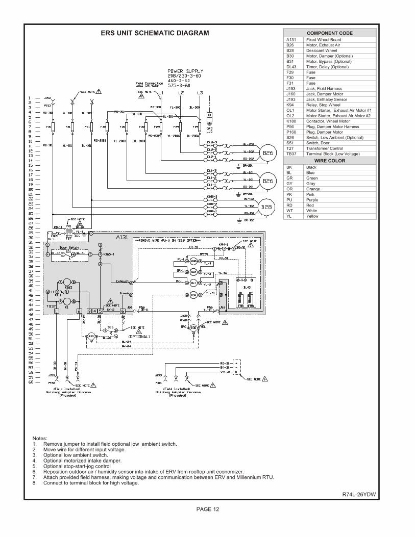
ERS UNIT SCHE MATIC DIAGRAM
PAGE 12
Notes:1. Re move jumper to in stall field op tional low am bi ent switch.2. Move wire for dif fer ent in put volt age.3. Op tional low am bi ent switch.4. Op tional mo tor ized in take damper.5. Op tional stop-start-jog con trol6. Re po si tion out door air / hu mid ity sen sor into in take of ERV from roof top unit economizer.7. At tach pro vided field har ness, mak ing volt age and com mu ni ca tion be tween ERV and Millennium RTU.8. Con nect to ter mi nal block for high volt age.
COM PO NENT CODE
A131 Fixed Wheel Board
B26 Mo tor, Ex haust Air
B28 Des ic cant Wheel
B30 Mo tor, Damper (Op tional)
B31 Mo tor, By pass (Op tional)
DL43 Timer, De lay (Op tional)
F29 Fuse
F30 Fuse
F31 Fuse
J153 Jack, Field Har ness
J160 Jack, Damper Mo tor
J193 Jack, En thalpy Sen sor
K94 Re lay, Stop Wheel
OL1 Mo tor Starter, Ex haust Air Mo tor #1
OL2 Mo tor Starter, Ex haust Air Mo tor #2
K180 Contactor, Wheel Motor
P56 Plug, Damper Mo tor Har ness
P160 Plug, Damper Mo tor
S26 Switch, Low Am bi ent (Op tional)
S51 Switch, Door
T27 Trans former Con trol
TB37 Ter mi nal Block (Low Volt age)
WIRE COLOR
BK Black
BL Blue
GR Green
GY Gray
OR Or ange
PK Pink
PU Purple
RD Red
WT White
YL Yel low

ERS UNIT WIR ING DIAGRAM
Notes:1. Re move jumper to in stall field op tional low am bi ent switch.2. Move wire for dif fer ent in put volt age.3. Op tional low am bi ent switch.4. Op tional mo tor ized in take damper.5. Op tional stop-start-jog con trol6. Re po si tion out door air / hu mid ity sen sor into in take of ERV from roof top unit economizer.7. At tach pro vided field har ness, mak ing volt age and com mu ni ca tion be tween ERV and Millennium RTU.8. Con nect to ter mi nal block for high volt age.
Unit#: 80- R74-01XL-23/-33/-43
Des ic cant Wheel for Roof top Unit208- 230/460V/575V (3 PH)
PA
GE
13

PA
GE
14
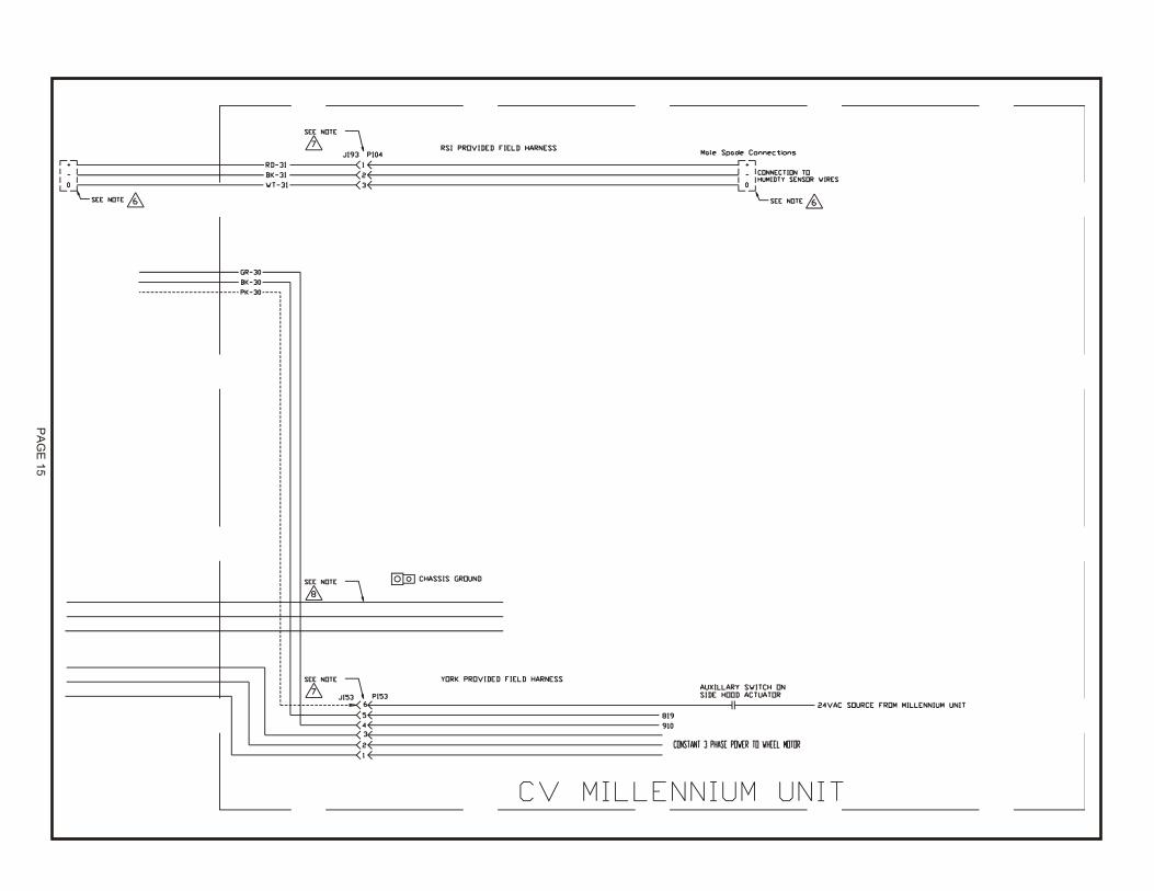
PA
GE
15

NOTES
Unitary 5005 NormanProducts York OKGroup Drive 73069
Supercedes: NothingSub ject to change with out no tice. Printed in U.S.A.Copy right © by Uni tary Prod ucts Group 2005. All rights re served.
035-20262-000-A-0205R74A-26YDW