ELENA E xtra L ow EN ergy A ntiproton Ring
20
LIS/ S. Maury 1 ELENA Extra Low ENergy Antiproton Ring 10 October 2011
-
Upload
quon-hubbard -
Category
Documents
-
view
32 -
download
0
description
ELENA E xtra L ow EN ergy A ntiproton Ring. Motivation to build ELENA. AD produces Antiproton beam at 5.3 MeV , most of AD experiments need antiprotons of 3 keV to 5 keV kinetic energy inside the trap. How antiprotons are decelerated today by experiments: - PowerPoint PPT Presentation
Transcript of ELENA E xtra L ow EN ergy A ntiproton Ring
LIS/ S. Maury 1
ELENA
Extra Low ENergy Antiproton Ring
10 October 2011
10 October 2011 LIS/ S. Maury 2
Motivation to build ELENAAD produces Antiproton beam at 5.3 MeV , most of AD experiments need
antiprotons of 3 keV to 5 keV kinetic energy inside the trap.
How antiprotons are decelerated today by experiments:• Antihydrogen experiments (ALPHA and ATRAP) use set of degraders to
slow 5.3 MeV beam from AD further down• Poor efficiency due to adiabatic blow up of beam emittances and scattering in
degraders, less than 0.1 % of AD beam is used.
• For ASACUSA, RFQD is used for antiproton deceleration down to around 100 keV kinetic energy.
• The deceleration is accompanied by adiabatic blow up (factor 7 in each plane) which causes significant reduction in trapping efficiency and in addition to that, RFQD is very sensitive to trajectory and optics mismatch errors
• About 70% beam is lost after passing through RFQD (transverse beam size too big)
• about 3-5% of antiprotons are captured after passing through degrader.
Gain in intensity with extra deceleration and cooling
• Deceleration of the antiproton beam in a small ring down to 100 keV with electron cooling increases the beam density.
• Emittances of beam passing through a degrader will be much smaller due to the use of the thinner degrader (100 keV beam instead of 5.3 MeV) => a gain of a factor 100 in intensity is expected for ALPHA, ATRAP and AEGIS.
• Because of the cooling, beam emittances after deceleration in ELENA will be much smaller than after RFQD => a gain of a factor 10 in intensity is expected for ASACUSA
10 October 2011 LIS/ S. Maury 3

ELENA in AD Hall
• Must be compact to fit in available space inside of AD Hall• The commissioning of ELENA could be done in parallel with physics
• To use existing experimental areas
• The existing AD ejection line is re-used
• To minimize the distance from ELENA to the experimental areas
• To have a new (extra) experimental area
10 October 2011 LIS/ S. Maury 4
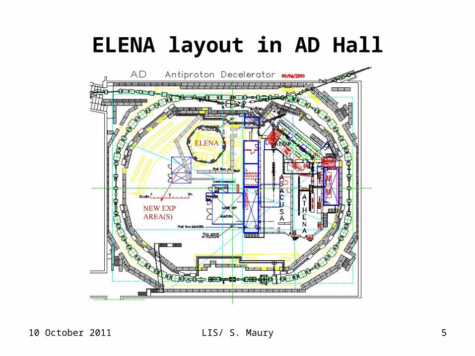
ELENA layout in AD Hall
10 October 2011 LIS/ S. Maury 5

ELENA injection line
• To make 82˚ bend, two magnets will be placed upstream to the shielding of AD Hall
• 5 or 6 quads used for matching of the Twiss functions (matching of dispersion not possible)
• Special care should be given to a crossing of injection and extraction lines
10 October 2011 LIS/ S. Maury 6

Injection into ELENA
10 October 2011 LIS/ S. Maury 7
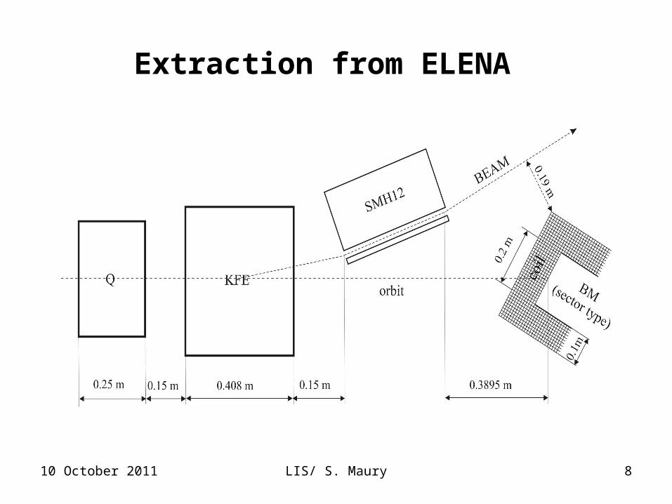
Extraction from ELENA
10 October 2011 LIS/ S. Maury 8
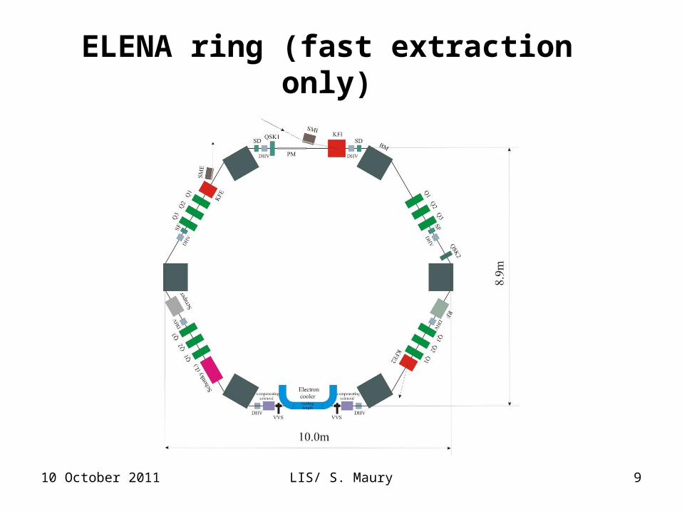
ELENA ring (fast extraction only)
10 October 2011 LIS/ S. Maury 9

ELENA optics
10 October 2011 LIS/ S. Maury 10

ELENA cycle
10 October 2011 LIS/ S. Maury 11
• No electron cooling is performed at injection energy, the beam is decelerated immediately.
• One intermediate cooling at 35 MeV/c is needed to avoid beam losses
• The expected cycle duration is in the range of 10 to 15 seconds

10 October 2011 LIS/ S. Maury 12
Electron cooler for ELENA
Cooling length lc, m 1
Beam cooled at momentum, MeV/c 35 & 13.7
Electron beam current Ie, mA 15 & 2
Cathode voltage at 100 keV, V 55
Maximal magnetic field in solenoid B0, G 100
Electron beam radius a, cm 2.5
Effects of cooler solenoid and compensatorson machine optics
• Tune shift due to solenoidal fields, maximal at low energy due to constant magnetic field in electron cooler solenoid and compensators
• Coupling in the part of cooling section (effects on antiproton beam alignment). No coupling outside of cooling section due to use of compensating solenoids
• Focusing effect of electron beam on antiproton beam -> tunes shift of ELENA ring
• Trims can be used to compensate partly these effects
10 October 2011 LIS/ S. Maury 13
10 October 2011 LIS/ S. Maury 14
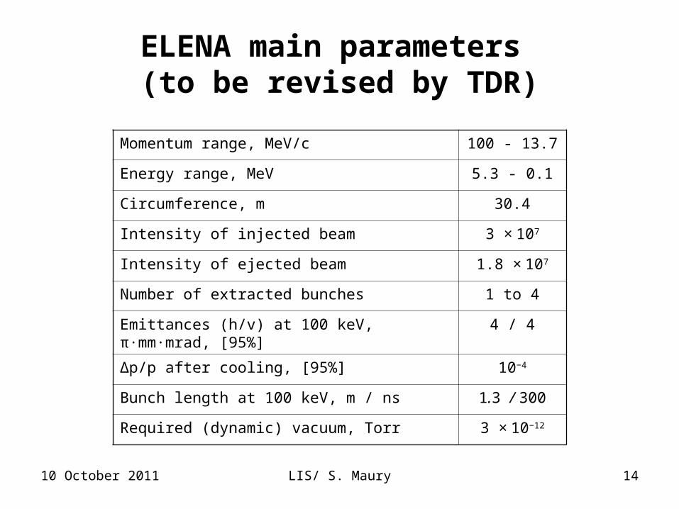
ELENA main parameters (to be revised by TDR)
Momentum range, MeV/c 100 - 13.7
Energy range, MeV 5.3 - 0.1
Circumference, m 30.4
Intensity of injected beam 3 × 10⁷
Intensity of ejected beam 1.8 × 10⁷
Number of extracted bunches 1 to 4
Emittances (h/v) at 100 keV, π·mm·mrad, [95%] 4 / 4
∆p/p after cooling, [95%] 10−4
Bunch length at 100 keV, m / ns 1.3 / 300
Required (dynamic) vacuum, Torr 3 × 10⁻¹²
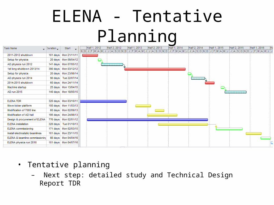
ELENA - Tentative Planning
• Tentative planning– Next step: detailed study and Technical Design Report TDR

Summary
• ELENA has been approved as a CERN project – Which means that we now have to build it and make it work as a
successful facility for this important research at low energy. – Help and contributions to ELENA construction from interested external institutes
vital (see ADUC & ELENA meeting )
• ELENA will begin a new era for antiproton physics for many years to come– Next step: detailed study and Technical Design Report (TDR)
– AD to be operated for at least one more decade (serious consolidation required)
• CERN is now engaged at two extreme fronts of particle physics, the very high and the very low energy side.
10 October 2011 LIS/ S. Maury Slide 16
Thanks for your attention!
10 October 2011 LIS/ S. Maury 17

What do we want to know from physics community?
• The intensity limit in ELENA is defined by emittance and bunch length
• Which maximal bunch length in ELENA ring is acceptable for each experiment? Length of 300 ns was defined in 2004, should it be revised?
• Which maximal emittance in ELENA ring is acceptable for experiments?
10 October 2011 LIS/ S. Maury 18

Which help do we want askfrom physics community for design studies?
• Electrostatic beam line studies: 1 MY
• Machine physics studies: ≥ 1 MY
10 October 2011 LIS/ S. Maury 19

Why did we choose
6-fold ring configuration? Initial ring circumference was 26.2m (1/7 of AD ring) -> not enough space to
place all required equipment, not possible to prepare extra experimental area (SPSC request) -> new circumference is 30.4 (1/6 of AD ring)
Advantages of the new rings:
• More flexibility for injection and extraction with the new layout
• The total length of bending magnets is shorter for hexagonal lattice compared with rectangular lattice -> more space for other equipment
• Minimal magnetic field in bending magnets (at 100 keV) increased form 399 Gs to 493 Gs – essential!
• Optics for 4 fold ring of 30 m long has unfavorable tunes (too much focusing in magnets), wide choice of tunes in 6 fold ring
• Smaller beta function values -> smaller aperture required by beam, relaxed requirement for vacuum
10 October 2011 LIS/ S. Maury 20