PI Submittal Package Cover Page Template - NEW€¦ · Kohler Certification Sheets ... Obtain the...
88
First in Quality, First in Service. Submittal Data R1 PREPARED FOR: Burrows LS Kohler Generator Model: 45REZG Kohler Transfer Switch Model: KCP-ANTB-0225S Proposal # 15572 100 Otter Street, Winnipeg, Manitoba, Canada, R3T 0M8 Phone: (204) 474-5909 Fax: (204) 474-5970 X 1 16-3523 B. Moore August 15, 2016
-
Upload
truongkhanh -
Category
Documents
-
view
217 -
download
0
Transcript of PI Submittal Package Cover Page Template - NEW€¦ · Kohler Certification Sheets ... Obtain the...

First in Quality, First in Service.
Submittal Data R1
PREPARED FOR:
Burrows LS
Kohler Generator Model:
45REZG
Kohler Transfer Switch Model:
KCP-ANTB-0225S
Proposal # 15572
100 Otter Street, Winnipeg, Manitoba, Canada, R3T 0M8 Phone: (204) 474-5909 Fax: (204) 474-5970
X1
16-3523B. Moore
August 15, 2016
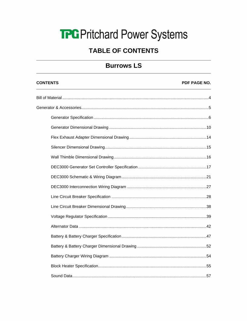
TABLE OF CONTENTS
Burrows LS
CONTENTS PDF PAGE NO.
Bill of Material ................................................................................................................................... 4
Generator & Accessories .................................................................................................................. 5
Generator Specification ....................................................................................................... 6
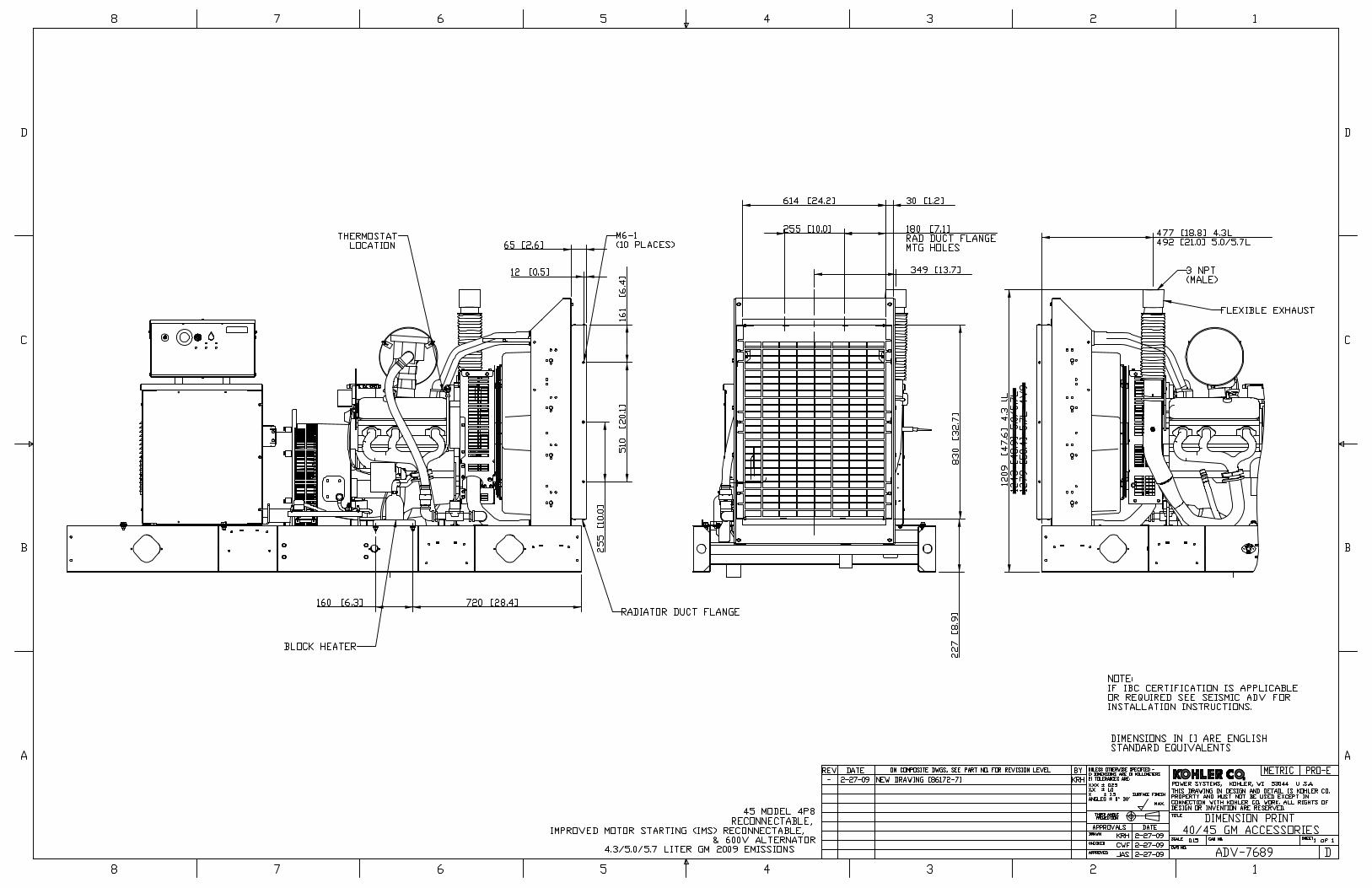
Generator Dimensional Drawing ....................................................................................... 10
Flex Exhaust Adapter Dimensional Drawing ..................................................................... 14
Silencer Dimensional Drawing........................................................................................... 15
Wall Thimble Dimensional Drawing ................................................................................... 16
DEC3000 Generator Set Controller Specification ............................................................. 17
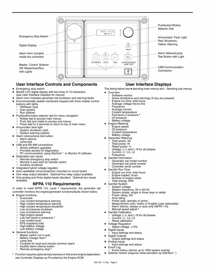
DEC3000 Schematic & Wiring Diagram ............................................................................ 21
DEC3000 Interconnection Wiring Diagram ....................................................................... 27
Line Circuit Breaker Specification ..................................................................................... 28
Line Circuit Breaker Dimensional Drawing ........................................................................ 38
Voltage Regulator Specification ........................................................................................ 39
Alternator Data .................................................................................................................. 42
Battery & Battery Charger Specification ............................................................................ 47
Battery & Battery Charger Dimensional Drawing .............................................................. 52
Battery Charger Wiring Diagram ....................................................................................... 54
Block Heater Specification ................................................................................................. 55
Sound Data ........................................................................................................................ 57
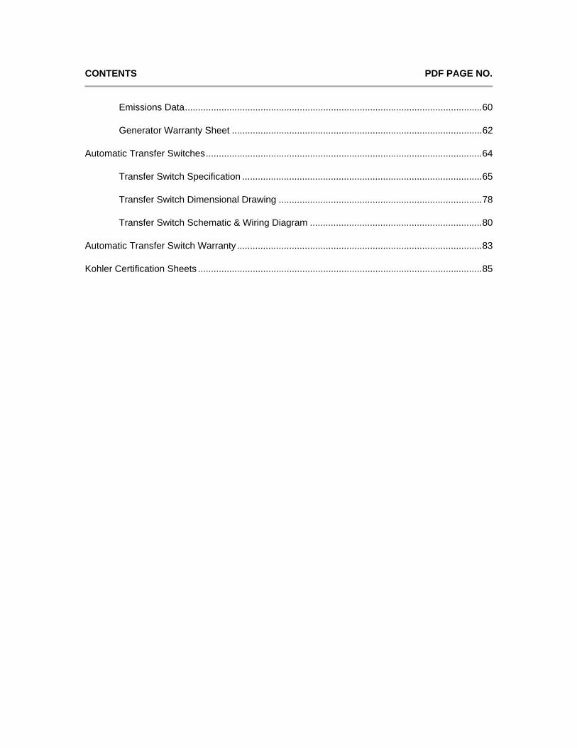
CONTENTS PDF PAGE NO.
Emissions Data .................................................................................................................. 60
Generator Warranty Sheet ................................................................................................ 62
Automatic Transfer Switches .......................................................................................................... 64
Transfer Switch Specification ............................................................................................ 65
Transfer Switch Dimensional Drawing .............................................................................. 78
Transfer Switch Schematic & Wiring Diagram .................................................................. 80
Automatic Transfer Switch Warranty .............................................................................................. 83
Kohler Certification Sheets ............................................................................................................. 85

BILL OF MATERIALS
Burrows LS
MODEL: ITEM DESCRIPTION: 45REZG 42kW/53kVA, 347/600 volt, 60Hz, Three Phase, Natural Gas Fuelled
Generator, Amperage Output – 51 Installed Accessories: - CSA Approval - Unit Mounted Radiator, 50 Deg. C, Ambient - Block Heater, 120V Single Phase, 1500W, Thermostatically Controlled - Generator Control Panel, Unit Mounted, DEC3000
o Run Relay o Emergency Stop Button o 2 Input, 5 Output Module o Pre-Alarm Senders
- Electronic Governor - Additional Gas Solenoid Valve - Line Circuit Breaker, 60 Amp, Thermal Mag Trip, 100%
o Auxiliary Contact o Alarm Switch
- Permanent Magnetic Generator (PMG) Model: 4P8 - Flexible Fuel Line - Battery Rack & Cables - Lead/Acid Starting Battery(s) - Vibration Isolators - Standard Duty Air Intake - Air Cleaner Restriction Indicator
Accessories Supplied Loose: - Battery Charger, Float w/Alarms, 12v – 10A - Flex Exhaust Connector - Critical Grade Silencer - Insulated Wall Thimble - Transfer Switch Model: KCP-ANTB-0225S
o Current Sensing o Line to Neutral Monitoring
Other Services: - First Fill of Lube Oil and Antifreeze/Coolant - 5 Year Extended Warranty - Standard Factory Test (CTR) - Set of Manuals - Delivery to Site, Offloading by Others - Start-up & Commissioning
As per D9.4, the contractor is required to off-load the goods

Generator & Accessories

Standard Features • Kohler Co. provides one-source responsibility for the generatingsystem and accessories.• The generator set and its components are prototype-tested, factory-built, and production-tested.• The 60 Hz generator set offers a UL 2200 listing.• The generator set accepts rated load in one step.• The 60 Hz generator set meets NFPA 110, Level 1, when equippedwith the necessary accessories and installed per NFPA standards.• A one-year limited warranty covers all systems and components.Two- and five-year extended warranties are also available.• EPA certified for Stationary Emergency Applications Alternator Features• The unique Fast-Response™ II excitation system delivers excellentvoltage response and short circuit capability using a permanent magnet(PM)-excited alternator.• The brushless, rotating-field alternator has broad rangereconnectability.
Generator Set Ratings Standby 130C Ratings
Alternator Voltage Ph Hz kW/kVA Amps4P8 347/600 3 60 42 / 53 51
RATINGS: All three-phase units are rated at 0.8 power factor. All single-phase units are rated at 1.0 power factor.Standby Ratings: Standby ratings apply to installations served by a reliable utility source. The standby rating is applicable to varying loads for the duration of a power outage.There is no overload capability for this rating. Ratings are in accordance with ISO-3046/1, BS 5514, AS 2789, and DIN 6271.Prime Power Ratings: Prime power ratings apply to installations where utility power is unavailable or unreliable. At varying load, the number of generator set operating hours is unlimited.A 10% overload capacity is available for one hour in twelve. Ratings are in accordance with ISO-8528/1, overload power in accordance with ISO-3046/1, BS 5514, AS 2789, and DIN 6271. For limited running time andbase load ratings, consult the factory.Obtain the technical information bulletin (TIB-101) on ratings guidelines for the complete ratings definitions.The generator set manufacturer reserves the right to change the design or specifications without notice and without any obligation or liability whatsoever.GENERAL GUIDELINES FOR DERATION: Altitude: Derate 1.3% per 100 m (328 ft.) elevation above 200 m (656 ft.). Temperature: Derate 3.0% per 10?C (18?F) temperature above 25?C (77?F).
45REZG
Natural Gas

Alternator SpecificationsSpecifications AlternatorAlternator manufacturer KohlerType 4-Pole, Rotating-FieldExciter type Brushless, Permanent-MagnetLeads, quantity 4P7, 4P8: 12, Reconnectable 4Q10: 4, 110-120/220-240Voltage regulator Solid State, Volts/HzInsulation NEMA MG1Insulation: Material Class HInsulation: Temperature Rise 130°C, StandbyBearing: quantity, type 1, SealedCoupling Flexible DiscAmortisseur windings FullVoltage regulation, no-load to full-load Permanent magnet (PM)alternator
Controller Dependent
One-Step Load Acceptance 100% of ratingUnbalanced load capability 100% of Rated Standby Current
• NEMA MG1, IEEE, and ANSI standards compliance for temperature rise and motor starting.• Sustained short-circuit current of up to 300% of the rated current for up to 10 seconds.• Sustained short-circuit current enabling down stream circuit breakers to trip without collapsing the alternator field.• Self-ventilated and dripproof construction.• Vacuum-impregnated windings with fungus-resistant epoxy varnish for dependability and long life.• Superior voltage waveform from a two-thirds pitch stator and skewed rotor.• Fast-Response™ II brushless alternator with brushless exciter for excellent load response.
ExhaustExhaust SystemExhaust Manifold Type DryExhaust flow at rated kW,m3/min. (cfm) 9.3 (327)Maximum allowable back pressure, kPa (in. Hg) 10.2 (3.0)Exhaust temperature at rated kW, dry exhaust, °C (°F) 649 (1200)Exh. outlet size at eng. hookup, mm (in.) 76 (3.0) OD
Engine ElectricalEngine Electrical SystemIgnition system Electronic, DistributorBattery charging alternator: Ground (negative/positive) NegativeBattery charging alternator: Volts (DC) 12Battery charging alternator: Ampere rating 70Starter motor rated voltage (DC) 12Battery, recommended cold cranking amps (CCA): Qty., rating for --18C (0?F)
One, 630
Battery voltage (DC) 12
FuelFuel SystemFuel type Natural GasFuel supply line inlet 1 NPTFNatural gas/LPG fuel supply pressure, kPa (in. H20). Fuel supplypressure measured at the generator set fuel inlet downstream of anyfuel system equipment accessories.
1.74-2.74 (7-11)
Model: 45REZG, continued

Fuel CompositionFuel CompositionNatural Gas: Methane, % by volume 90 min.Natural Gas: Ethane, % by volume 4.0 max.Natural Gas: Propane, % by volume 1.0 max.Natural Gas: Propene, % by volume 0.1 max.Natural Gas: C4 and higher, % by volume 0.3 max.Natural Gas: Sulfur, ppm mass 25 max.Natural Gas: Lower heating value, kJ/m3 (Btu/ft3), min. 33.2 (890)* Fuels with other compositions may be acceptable. If your fuel is outside the listed specifications, contact your local distributor for furtheranalysis and advice.
LubricationLubrication SystemType Full PressureOil pan capacity, L (qt.) 4.3 (4.5)Oil pan capacity with filter, L (qt.) 5.7 (6.0)Oil filter: quantity, type 1, Cartridge
CoolingRadiator SystemAmbient temperature, °C (°F) 50 (122)Engine jacket water capacity, L (gal.) 6.8 (1.8)Radiator system capacity, including engine, L (gal.) 19.7 (5.2)Engine jacket water flow, Lpm (gpm) 106.0 (28)Heat rejected to cooling water at rated kW, dry exhaust, kW (Btu/min.) 40.8 (2320)Water pump type CentrifugalFan diameter, including blades, mm (in.) 533 (21)Fan, kWm (HP) 1.5 (2.0)Max. restriction of cooling air, intake and discharge side of radiator,kPA (in. H20)
0.125 (0.5)
Enclosure with enclosed silencer reduces ambient temperature capability by 5°C (9°F)
Operation RequirementsAir RequirementsRadiator-cooled cooling air, m3/min. (scfm) * 142 (5000)Combustion air, m3/min. (cfm) 2.78 (98)Heat rejected to ambient air: Engine, kW (Btu/min.) 19.2 (1090)Heat rejected to ambient air: Alternator, kW (Btu/min.) 7.4 (420)Radiator-cooled cooling air, m3/min. (scfm) * 142 (5000)Combustion air, m3/min. (cfm) 2.78 (98)Heat rejected to ambient air: Engine, kW (Btu/min.) 19.2 (1090)Heat rejected to ambient air: Alternator, kW (Btu/min.) 7.4 (420)
*Air density = 1.20 kg/m3 (0.075 lbm/ft3)
Fuel ConsumptionNatural Gas, m3/hr. (cfh) at % load RatingStandby Fuel Consumption at 100% load 16.5 m3/hr. (584 cfh)Standby Fuel Consumption at 75% load 13.8 m3/hr. (486 cfh)Standby Fuel Consumption at 50% load 10.2 m3/hr. (360 cfh)
Model: 45REZG, continued

Standby Fuel Consumption at 25% load 7.7 m3/hr. (272 cfh)Prime Fuel Consumption at 100% load 15.7 m3/hr. (552 cfh)Prime Fuel Consumption at 75% load 12.7 m3/hr. (448 cfh)Prime Fuel Consumption at 50% load 9.5 m3/hr. (336 cfh)Prime Fuel Consumption at 25% load 7.6 m3/hr. (267 cfh)
Dimensions and WeightsDim Weight Spec Dim Weight ValueFuel LP Gas or Natural GasEngine Manufacturer General MotorsOverall Size, L x W x H, mm (in.): Wide Skid 2200 x 1040 x 1172 (86.6 x 40.9 x 46.1)Overall Size, L x W x H, mm (in.): Narrow Skid 2200 x 864 x 1172 (86.6 x 34.0 x 46.1)Weight (radiator model), wet, kg (lb.): 655 (1456)
NOTE: This drawing is provided for reference only and should not be used for planning installation. Contact your local distributor for moredetailed information.
Model: 45REZG, continued
maximum dimensions:length 2000mmwidth 864mmexhaust outlet height 813mm


SilencersModel SM2
No InsulationCylindricalStandard
Critical25-30 dBA
Applications and Performance Selecting The Right Silencer
Model SM2 is a Cylindrical Multi ChamberReactive Silencer used where moderatelevel of attenuation is required.Availableoptions: stainless steel, mounting brackets,flex connections and other accessories.
In selecting a proper size silencer for agiven application, consideration must begiven to the total system back pressure aswell as exhaust velocity. In order to retainexpected silencer insertion loss, exhaustflow velocity for Model SM2 must notexceed 11,500 ft/min. Log on to our onlinesizing software to guide you in making theright selection.
TRANSMISSION LOSS
PRESSURE DROP
Model A D L1 L2 L3 O N N M M Weight
Outlet Dia EIEO SIEO SISO O Min Max Min Max
SM2-1.5 1.5 8 26 23 20 7 3 10 3 5
SM2-2 2 9 30 27 24 7.5 4 13 4 6
SM2-2.5 2.5 10 34 31 28 8 5 15 5 7
SM2-3 3 12 36 33 30 9 5 16 5 8
SM2-3.5 3.5 12 42 39 36 9 5 20 5 10
SM2-4 4 12 50 46 42 10 6 24 6 11
SM2-5 5 14 54 50 46 11 6 26 6 12
SM2-6 6 16 63 59 55 12 7 31 7 15
SM2-8 8 22 68 64 60 15 9 33 9 16
SM2-10 10 26 92 88 84 17 12 47 12 22
SM2-12 12 30 98 94 90 19 14 50 14 23
SM2-14 14 36 104 99 94 23 17 51 17 24
SM2-16 16 40 118 113 108 25 17 59 17 28
SM2-18 18 42 127 122 117 26 18 64 18 30
SM2-20 20 48 144 139 134 29 21 74 21 35
SM2-22 22 54 154 149 144 32 23 79 23 38
SM2-24 24 60 163 158 153 35 26 83 26 41
SM2-26 26 64 181 176 171 37 28 94 28 46
SM2-28 28 68 198 193 188 39 29 104 29 51
SM2-30 30 72 214 209 204 41 32 114 32 55
All sizes and measurements are in inches and pounds
The silencer may be installed at any angle. When mounting horizontally allow for a 3/8”/ft incline to provide proper drainage.Mounting brackets, side inlet connections, clean out doors and companion flanges are available at additional cost.The silencer is of an all welded construction and the exterior surfaces are given a coat of high temperature paint.
Powered by TCPDF (www.tcpdf.org)

SMSS I L E N C E R S I N C .
Toll Free 800 459 1512Phone 905 459 1512Fax 905 459 3138www.SMSsilencers.com
Wall and Roof ThimblesInsulated
SMS Silencers Inc.153A Rutherford Road SouthBrampton, OntarioCanada L6W 3N5
www.SMSsilencers.comREV. 01-07
When selecting a proper size thimble for a given application, select the thimble based on the material Sch 40 pipe (P) or OD tubing (T).
Applications and Performance
Insulated wall and roof thimbles are designed as per National Fire Protection Standards NFPA 37. The standard length of thimbles are 24” in total length with a fixed welded on wall mounting plate at 6”. All thimble units come complete with two wall plates and rainguard.
Selecting The Right Thimble
in (mm) in (mm) in (mm) in (mm) in (mm) in (mm) Lb (Kg)
SMWT-2-P-I 2 5/8 (67) 14 (356) 16 (406) 20 (508) 6 (152) 24 (610) 103 (47)
SMWT-2.5-P-I 3 1/8 (79) 14 (356) 16 (406) 20 (508) 6 (152) 24 (610) 103 (47)
SMWT-3-P-I 3 5/8 (92) 16 (406) 18 (457) 22 (559) 6 (152) 24 (610) 111 (50)
SMWT-3.5-P-I 4 1/8 (105) 16 (406) 18 (457) 22 (559) 6 (152) 24 (610) 111 (50)
SMWT-4-P-I 4 5/8 (117) 16 (406) 18 (457) 22 (559) 6 (152) 24 (610) 125 (57)
SMWT-5-P-I 5 3/4 (146) 18 (457) 20 (508) 24 (610) 6 (152) 24 (610) 146 (66)
SMWT-6-P-I 6 3/4 (171) 18 (457) 20 (508) 24 (610) 6 (152) 24 (610) 146 (66)
SMWT-8-P-I 8 7/8 (225) 20 (508) 22 (559) 26 (660) 6 (152) 24 (610) 181 (82)
SMWT-10-P-I 11 (279) 22 (559) 24 (610) 28 (711) 6 (152) 24 (610) 203 (92)
SMWT-12-P-I 13 (330) 24 (610) 26 (660) 32 (813) 6 (152) 24 (610) 225 (102)
SMWT-14-P-I 14 1/4 (362) 26 (660) 28 (711) 34 (864) 6 (152) 24 (610) 251 (114)
SMWT-16-P-I 16 1/4 (413) 28 (711) 30 (762) 36 (914) 6 (152) 24 (610) 272 (124)
SMWT-18-P-I 18 1/4 (464) 30 (762) 32 (813) 38 (965) 6 (152) 24 (610) 302 (137)
SMWT-20-P-I 20 1/4 (514) 32 (813) 34 (864) 40 (1016) 6 (152) 24 (610) 315 (143)
SMWT-22-P-I 22 1/4 (565) 34 (864) 36 (914) 42 (1067) 6 (152) 24 (610) 337 (153)
SMWT-24-P-I 24 1/4 (616) 36 (914) 38 (965) 44 (1118) 6 (152) 24 (610) 344 (156)
SMWT-26-P-I 26 1/4 (667) 38 (965) 40 (1016) 46 (1168) 6 (152) 24 (610) 375 (170)
SMWT-28-P-I 28 1/4 (718) 40 (1016) 42 (1067) 48 (1219) 6 (152) 24 (610) 392 (178)
SMWT-30-P-I 30 1/4 (768) 42 (1067) 44 (1118) 50 (1270) 6 (152) 24 (610) 435 (198)
Part NumberC W O M D Weight A
in (mm) in (mm) in (mm) in (mm) in (mm) in (mm) Lb (Kg)
SMWT-2-T-I 2 1/8 (54) 14 (356) 16 (406) 20 (508) 6 (152) 24 (610) 103 (47)
SMWT-2.5-T-I 2 5/8 (67) 14 (356) 16 (406) 20 (508) 6 (152) 24 (610) 103 (47)
SMWT-3-T-I 3 7/8 (98) 16 (406) 18 (457) 22 (559) 6 (152) 24 (610) 111 (50)
SMWT-3.5-T-I 3 5/8 (92) 16 (406) 18 (457) 22 (559) 6 (152) 24 (610) 111 (50)
SMWT-4-T-I 4 1/8 (105) 16 (406) 18 (457) 22 (559) 6 (152) 24 (610) 125 (57)
SMWT-5-T-I 5 1/8 (130) 18 (457) 20 (508) 24 (610) 6 (152) 24 (610) 146 (66)
SMWT-6-T-I 6 1/8 (156) 18 (457) 20 (508) 24 (610) 6 (152) 24 (610) 146 (66)
Part NumberM D Weight C A W O
Model SMWT-I

Generator Set Controller
Kohlerr Decision-Makerr 3000 ControllerGeneral Description and FunctionThe Decision-Makerr 3000 generator set controller providesadvanced control, system monitoring, and system diagnosticsfor optimum performance.
The Decision-Makerr 3000 controller meets NFPA 110, Level 1when equipped with the necessary accessories and installed perNFPA standards.
The Decision-Makerr 3000 controller uses a patented hybridvoltage regulator and unique software logic to manage alternatorthermal overload protection features normally requiringadditional hardware. Additional features include:
D A digital display and pushbutton/rotary selector dial provideeasy local access to data.
D Measurements selectable in metric or English units.
D The controller can communicate directly with a personalcomputer via a network or serial configuration usingSiteTecht or Monitor III software.
D The controller supports Modbusr protocol. Use with serialbus or Ethernet networks. (Ethernet requires an externalModbusr/Ethernet converter module.)
D Scrolling display shows critical data at a glance.
D Digital display of power metering (kW and kVA).
D Integrated hybrid voltage regulator providing 0.5%regulation.
D Built-in alternator thermal overload protection.
Modbusr is a registered trademark of Schneider Electric.
Industrial Generator Set Accessories
Decision-Makerr 3000
Volts L1--L2:480.0 V
G6-100 11/15g Page 1
G6-100 11/15g Page 2
FAULT
OFF/RESET AUTO RUN ALARM SILENCE/LAMP TEST
Volts L1‐L2:480.0 V
Emergency Stop Switch
Digital Display
Master Control ButtonsOff--Reset/Auto/Runwith Lights
Pushbutton/RotarySelector Dial
Alarm Silence/LampTest Button with Light
Annunciator Fault LightRed--Shutdown,Yellow--Warning
USB CommunicationConnection
Alarm Horn (locatedinside the controller)
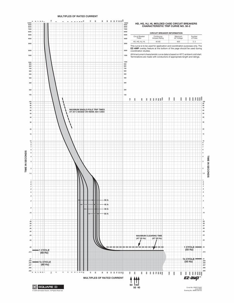
User Interface Controls and ComponentsD Emergency stop switchD Backlit LCD digital display with two lines of 12 characters
(see User Interface Displays for menus)D Alarm horn indicates generator set shutdown and warning faultsD Environmentally sealed membrane keypad with three master control
buttons with lightsd Off/Reset (red)d Auto (green)d Run (yellow)
D Pushbutton/rotary selector dial for menu navigationd Rotate dial to access main menusd Push dial and rotate to access sub menusd Press dial for 3 seconds to return to top of main menu
D Annunciator fault lightd System shutdown (red)d System warning (yellow)
D Alarm silence/lamp test buttond Alarm silenced Lamp test
D USB and RS-485 connectionsd Allows software upgradesd Provides access for diagnosticsd PC communication using SiteTecht or Monitor III software
D Dedicated user inputsd Remote emergency stop switchd Remote 2-wire start for transfer switchd Auxiliary shutdown
D Integrated hybrid voltage regulatorD Auto-resettable circuit protection mounted on circuit board.D One relay output standard. Optional five relay output available.D One analog and three digital inputs standard. Optional two inputs
available.NFPA 110 Requirements
In order to meet NFPA 110, Level 1 requirements, the generator setcontroller monitors the engine/generator functions/faults shown below.D Engine functions:d Overcrankd Low coolant temperature warningd High coolant temperature warningd High coolant temperature shutdownd Low oil pressure shutdownd Low oil pressure warningd High engine speedd Low fuel (level or pressure) *d Low coolant leveld EPS supplying loadd High battery voltaged Low battery voltage
D General functions:d Master switch not in autod Battery charger fault *d Lamp testd Contacts for local and remote common alarmd Audible alarm silence buttond Remote emergency stop *
* Function requiresoptional input sensors or kits and is enginedependent,see Controller Displays as Provided by the Engine ECM.
User Interface DisplaysThe listing below has D denoting main menus and d denoting sub-menus.D Overviewd Software versiond Active shutdowns and warnings (if any are present)d Engine run time, total hoursd Average voltage line-to-lined Frequencyd Average currentd Coolant temperatured Fuel level or pressure *d Oil pressured Battery voltage
D Engine Meteringd Engine speedd Oil pressured Coolant temperatured Battery voltage
D Generator Meteringd Total power, VAd Total power, Wd Rated power, %d Voltage, L--L and L--N for all phasesd Current, L1, L2, L3d Frequency
D GenSet Informationd Generator set model numberd Generator set serial numberd Controller serial number
D GenSet Run Timed Engine run time, total hoursd Engine loaded, hoursd Number of engine startsd Total energy, kWh
D GenSet Systemd System voltaged System frequency, 50 or 60 Hzd System phase, single or three (wye or delta)d Power rating, kWd Amp ratingd Power type, standby or primed Measurement units, metric or English (user selectable)d Alarm silence, always or auto only (NFPA 110)d Manual speed adjust *
D GenSet Calibrationd Voltage, L--L and L--N for all phasesd Current, L1, L2, L3d Reset calibration
D Voltage Regulationd Adjust voltage, 10%
D Digital Inputsd Input settings and status
D Digital Outputsd Output settings and status
D Analog Inputsd Input settings and status
D Event Logd Event history (stores up to 1000 system events)
D Selector Switch (requires initial activation by SiteTecht)

G6-100 11/15g Page 3
Controller Features
D AC Output Voltage Regulator Adjustment. The voltageadjustment provides a maximum of 10% of the system voltage.
D Alarm Silence. The controller can be set up to silence the alarmhorn only when in the AUTO mode for NFPA-110 application orAlways for user convenience.
D Alternator Protection. The controller provides generator setoverload and short circuit protection matched to each alternator forthe particular voltage/phase configuration.
D Automatic Restart. The controller automatic restart feature initiatesthe start routine and recrank after a failed start attempt.
D Common Failure Relay. This relay is integrated on the controllercircuit board. Contacts are rated 2 amps at 32 VDC or 0.5 amp at120 VAC.
D Communication. Controller communication is available.
D Cyclic Cranking. The controller has programmable cyclic cranking.
D ECM Diagnostics. The controller displays engine ECM fault codedescriptions to help in engine troubleshooting.
D Engine Start Aid. The starting aid feature provides control for anoptional engine starting aid.
D Event Logging. The controller keeps a record (up to 1000 entries)for warning and shutdown faults. This fault information becomes astored record of system events and can be reset.
D Historical Data Logging. Total number of generator set successfulstarts is recorded and displayed.
D Integrated Hybrid Voltage Regulator. The voltage regulatorprovides 0.5% no-load to full-load regulation with three-phasesensing.
D Lamp Test. Press the alarm silence/lamp test button to verifyfunctionality of the indicator lights.
D LCD Display. Adjustable contrast for improving visibility.
D Measurement Units. The controller provides selection of English ormetric displays.
D Power Metering. Controller digital display provides kW and kVA.
D Programming Access (USB). Provides software upgrades anddiagnostics.
D Remote Reset. The remote reset function resets faults and allowsrestarting of the generator set without going to the master controlswitch off/reset position.
D Remote Monitoring Panel. The controller is compatible with theKohlerr Remote Serial Annunciator.
D Run Time Hourmeter. The generator set run time is displayed.
D Time Delay Engine Cooldown (TDEC). The TDEC provides a timedelay before the generator set shuts down.
D Time Delay Engine Start (TDES). The TDES provides a time delaybefore the generator set starts.
D Voltage Selection Menu. This menu provides the capability ofquickly switching controller voltage calibrations. Requires initialactivation using SiteTecht software. NOTE: Generator set outputleads require voltage reconnection.
Controller FunctionsThe following chart shows which functions cause a warning or shutdown.All functions are available as relay outputs.
Warning causes the fault light to show yellow and sounds the alarm hornsignaling an impending problem.
Shutdown causes the fault light to show red, sounds the alarm horn, andstops the generator set.
WarningFunction
ShutdownFunction
Engine FunctionsCritically high fuel level * d
ECM communication loss D
ECM diagnostics D D
Engine over speed D[
Engine start aid activeEngine under speed D
Fuel tank leak * d d
High battery voltage D
High coolant temperature D D[
High fuel level * d
Low battery voltage D
Low coolant level D
Low coolant temperature D
Low cranking voltage D
Low engine oil level * d d
Low fuel level (diesel models) * d d
Low fuel pressure (gas models) * d
Low oil pressure D D[
No coolant temperature signal D
No oil pressure signal D
Overcrank D[
Speed sensor fault D
General FunctionsAlarm horn silencedAnalog inputs d d
Battery charger fault * D
Chicago code active *Common fault (includes [) D
Common warning D
Digital inputs d d
Emergency stop D[
Engine cooldown (delay) activeEngine start delay activeEngine startedEngine stoppedEPS supplying loadGenerator runningInput/output communication loss D
Internal failure D
Master switch not in auto D
NFPA 110 alarm activeRemote startSystem ready
Generator FunctionsAC sensing loss D D
Alternator protection D
Ground fault input * D
kW overload D
Locked rotor D
Overfrequency D
Overvoltage (each phase) D
Underfrequency D
Undervoltage (each phase) D
D Standard functiond Available user function* Function requiresoptional input sensors or kits and is enginedependent;see Controller Displays as Provided by the Engine ECM.
[ Items included with common fault shutdown

2009, 2010, 2012, 2013, 2014, 2015 by Kohler Co., All rights reserved.
DISTRIBUTED BY:
G6-100 11/15g Page 4
Controller Displays as Provided by the Engine ECM (availability subject to change by the engine manufacturer)Display GM/PSI Doosan John Deere (JDEC) Volvo (EMS II) Volvo (EDC III) DD/MTU (ADEC)
Ambient temperature XCharge air pressure X X X X XCharge air temperature X X X X XCoolant level X X XCoolant pressure X XCoolant temperature X X X X X XCrankcase pressure X XECM battery voltage X X XECM fault codes X X X X X XECM serial number XEngine model number X XEngine serial number X XEngine speed X X X X X XFuel pressure X XFuel rate X X X X X XFuel temperature X X X XOil level XOil pressure X X X X X XOil temperature X X XTrip fuel X X X
NOTE: 15--60REOZK (KohlerKDI engines) donot includeanECMas standard equipment. REOZMD/ROZMC(Mitsubishi engines) have anECMbut donot send signals to the generator set controller.
Controller SpecificationsDecision-Makerr 3000—Software Version 3.11 or higher
D Power source with circuit protection: 12- or 24-volt DCD Power drain: 200 milliamps at 12 VDC or 100 milliamps at 24 VDCD Humidity range: 5% to 95% noncondensingD Operating temperature range: --40C to +70C (--40F to +158F)D Storage temperature range: --40C to +85C (--40F to +185F)D Standards:d CE Directived NFPA 99d NFPA 110, Level 1d CSA 282-09d UL 508d ASTM B117 (salt spray test)
D Panel dimensions—W x H, 229 x 160 mm (9.0 x 6.3 in.)
Communication and PC SoftwareAvailable Options
Refer to G6-76 Monitor III Software and the communication literature foradditional communication and PC software information includingModbusr communication.
- Monitor III Software for Monitoring and Control(Windowsr-based user interface)
- Converter, Modbusr/Ethernet. Supports a power system usingcontrollers accessed via the Ethernet. Converter is supplied with anIP address by the site administrator. Refer to G6-79 for converterdetails.
- Converter, RS-232/RS-485. Supports a power system usingcontrollers accessed via a serial (RS-232) connection.
Decision-Makerr 3000 Available Options- Float/Equalize Battery Charger available with 6 or 10 amp DC
volt output. The 10 amp models are available with and withoutNFPA alarm to signal a battery charger fault.
- Manual Speed Adjust available for applications using closedtransition ATS. Adjustment range for 60 Hz: 1751--1849 rpm(58.2--61.8 Hz) and for 50 Hz: 1451--1549 rpm (48.2--51.8 Hz).
- Prime Power Switch prevents battery drain during generator setnon-operation periods and when the generator set battery cannot bemaintained by an AC battery charger.
- Remote Emergency Stop Switch available as a wall mountedpanel to remotely shut down the generator set.
- Remote Monitoring Panel. The Kohlerr Remote SerialAnnunciator (RSA) enables the operator to monitor the status of thegenerator set from a remote location, which may be required forNFPA 99 and NFPA 110 installations.
- Run Relay provides a relay indicating that the generator set isrunning.
- Shunt Trip Wiring provides relay outputs to trip a shunt trip circuitbreaker and to signal the common fault shutdowns. Contacts ratedat 10 amps at 28 VDC or 120VAC.
- Two Input/Five Output Module provides a generator set mountedpanel with two inputs and five relay outputs.
Modbusr is a registered trademark of Schneider Electric.
Windowsr is a registered trademark of Microsoft Corporation.
Kohler Power SystemsAsia Pacific Headquarters7 Jurong Pier RoadSingapore 619159Phone (65) 6264-6422, Fax (65) 6264-6455
KOHLER CO., Kohler, Wisconsin 53044 USAPhone 920-457-4441, Fax 920-459-1646For the nearest sales and service outlet in theUS and Canada, phone 1-800-544-2444KOHLERPower.com
Availability is subject to change without notice. Kohler Co. reserves theright to change the design or specificationswithout notice andwithout anyobligation or liability whatsoever. Contact your local Kohlerr generatorset distributor for availability.

Wiring Schematics


Industrial Generator Set Accessories
Standard FeaturesD The line circuit breaker interrupts the generator set
output during a short circuit and protects the wiringwhen an overload occurs. Use the circuit breaker tomanually disconnect the generator set from the loadduring generator set service.
D Circuit breaker kits are mounted to the generator setand are provided with load-side lugs and neutral busbar.
D Kohler Co. offers a wide selection of molded-caseline circuit breaker kits including single, dual, andmultiple configurations for each generator set.
D Four types of line circuit breakers are available:(see page 2 for definitions and pages 3 and 4 forapplication details)
d Magnetic trip
d Thermal magnetic trip
d Electronic trip
d Electronic with ground fault (LSIG) trip
D In addition, line circuit breakers are offered with 80%and 100% ratings.
D Single line circuit breaker kits allow circuit protectionof the entire electrical system load.
D Dual line circuit breaker kits allow circuit protectionof selected priority loads from the remainingelectrical system load.
D Multiple line circuit breaker kits with field connectionbarrier allow circuit protection for specialapplications (350--2250 kW).
D Line circuit breakers comply with the following codesand standards unless otherwise stated.
d UL 489 Molded Case Circuit Breakers
d UL 1077 Supplementary Protectors
d UL 2200 Stationary Engine Generator Assemblies
Line Circuit Breakers 15--2250 kW
Dual Circuit Breaker Kit with Neutral Bus Bar15--300 kW Model Shown
Single Circuit Breaker Kit with Neutral Bus Bar15--300 kW Model Shown
Multiple Circuit Breaker Kits with Neutral Bus Bar350--2250 kW Model Shown
(also applies to some 300 kW models)
G6-88 12/15i Page 1

G6-88 12/15i Page 2
Line Circuit Breaker TypesMagnetic TripThe magnetic trip features an electromagnet in series with theload contacts and a moveable armature to activate the tripmechanism. When a sudden and excessive current such asa short circuit occurs, the electromagnet attracts the armatureresulting in an instantaneous trip (UL 1077 circuit breakers).
Thermal Magnetic TripThermal magnetic trip contains a thermal portion with abimetallic strip that reacts to the heat produced from the loadcurrent. Excessive current causes it to bend sufficiently totrip the mechanism. The trip delay is dependant on the durationand excess of the overload current. Elements are factory-calibrated. A combination of both thermal and magneticfeatures allows a delayed trip on an overload and aninstantaneous trip on a short circuit condition.
Electronic TripThese line circuit breakers use electronic controls and miniaturecurrent transformers to monitor electrical currents and trip whenpreset limits are exceeded.
LI breakers are a combination of adjustable trip functionsincluding long-time ampere rating, long-time delay, andinstantaneous pickup. LSI breakers have all of the LI breakerfeatures plus short-time pickup, short-time delay, anddefeatable instantaneous pickup. LSIG breakers have all of theLSI breaker features plus ground-fault pickup and delay.
Electronic with Ground Fault TripThe ground fault trip feature is referred to as LSIG in thisdocument. Models with LSIG compare current flow in phaseand neutral lines, and trip when current unbalance exists.
Ground fault trip units are an integral part of the circuit breakerand are not available as field-installable kits. The ground faultpickup switch sets the current level at which the circuit breakerwill trip after the ground fault delay. Ground fault pickup valuesare based on circuit breaker sensor plug only and not on therating plug multiplier. Changing the rating plug multiplier hasno effect on the ground fault pickup values.
80% Rated Circuit BreakerMost molded-case circuit breakers are 80% rated devices.An 80% rated circuit breaker can only be applied at 80% of itsrating for continuous loads as defined by NFPA 70. Circuitconductors used with 80% rated circuit breakers are requiredto be rated for 100% of the circuit breaker’s rating.
The 80% rated circuit breakers are typically at a lower costthan the 100% rated circuit breaker but load growth is limited.
100% Rated Circuit BreakerApplications where all UL and NEC restrictions are met can use100% rated circuit breakers where 100% rated circuits can carry100% of the circuit breaker and conductor current rating.
The 100% rated circuit breakers are typically at a higher costthan the 80% rated circuit breaker but have load growthpossibilities.
When applying 100% rated circuit breakers, comply with thevarious restrictions including UL Standard 489 and NECSection 210. If any of the 100% rated circuit breaker restrictionsare not met, the circuit breaker becomes an 80% rated circuitbreaker.
Line Circuit Breaker Options- Alarm Switch
The alarm switch indicates that the circuit breaker is in a trippedposition caused by an overload, short circuit, ground fault, theoperation of the shunt trip, an undervoltage trip, or the push-to-trip pushbutton. The alarm resets when the circuit breaker isreset.
- Auxiliary Contacts
These switches send a signal indicating whether the maincircuit breaker contacts are in the open or closed position.
- Breaker Separators (350--2250 kW)
Provides adequate clearance between breaker circuits.
- Bus Bars
Bus bar kits offer a convenient way to connect load leads to thegenerator set when a circuit breaker is not present.15--300 kW. Bus bar kits are available on alternators with leadsfor connection to the generator set when circuit breakers are notordered.350--2250 kW. A bus bar kit is provided on the right side of theunit when no circuit breaker is ordered. Bus bars are alsoavailable in combination with circuit breakers or other bus barson the opposite side of the junction box. On medium voltage(3.3 kV and above) units, a bus bar kit is standard.
- Field Connection Barrier
Provides installer wiring isolation from factory connections.
- Ground Fault Annunciation
A relay contact for customer connection indicates a groundfault condition and is part of a ground fault alarm.
- Lockout Device (padlock attachment)
This field-installable handle padlock attachment is available formanually operated circuit breakers. The attachment canaccommodate three padlocks and will lock the circuit breakerin the OFF position only.
- Neutral Lugs
Various neutral lug sizes are available to accommodate multiplecable sizes for connection to the bus bar only.
- Overcurrent Trip Switch
The overcurrent trip switch indicates that the circuit breaker hastripped due to overload, ground fault, or short circuit and returnsto the deenergized state when the circuit breaker is reset.
- Shunt Trip, 12 VDC or 24 VDC
A shunt trip option provides a solenoid within the circuit breakercase that, when momentarily energized from a remote source,activates the trip mechanism. This feature allows the circuitbreaker to be tripped by customer-selected faults such asalternator overload or overspeed. The circuit breaker mustbe reset locally after being tripped. Tripping has priority overmanual or motor operator closing.
- Shunt Trip Wiring
Connects the shunt trip to the generator set controller.
- Undervoltage Trip, 12 VDC or 24 VDC
The undervoltage trips the circuit breaker when the controlvoltage drops below the preset threshold of 35%--70% of therated voltage.

G6-88 12/15i Page 3
15--300 kW Line Circuit Breaker Specifications80% Rating Circuit Breaker
Gen. SetkW
Alt.Model
AmpereRange Trip Type
C. B.FrameSize
15--804D/4E/4P/4PX/4Q/4QX
30--100
Magnetic, UL 1077
E(480 Vmax.)
Magnetic, UL 1077with 12 V shunt trip
Magnetic, UL 1077with 24 V shunt trip
15--150 Thermal magnetic
HD60--150
Electronic LI
Electronic LSIG
175--250 Thermal magnetic
JD250
Electronic LI
Electronic LSIG
300--400 Thermal magnetic LA
60--2004RX/4S/4SX/4TX/4V
30--100
Magnetic, UL 1077
E(480 Vmax.)
Magnetic, UL 1077with 12 V shunt trip
Magnetic, UL 1077with 24 V shunt trip
15--150 Thermal magnetic
HD60--150
Electronic LI
Electronic LSIG
175--250 Thermal magnetic
JD250
Electronic LI
Electronic LSIG
300--400 Thermal magnetic LA
400--600Electronic LI
LGElectronic LSIG
700--800 Thermal magnetic MG
1000--1200 Thermal magnetic
PG800--1200
Electronic LSI
Electronic LSIG
200--3004UA/
4M6226
15--150 Thermal magnetic
HD60--150
Electronic LI
Electronic LSIG
175--250 Thermal magnetic
JD250
Electronic LI
Electronic LSIG
300--400 Thermal magnetic LA
400--600Electronic LI
LGElectronic LSIG
700--800 Thermal magnetic MG
1000--1200 Thermal magnetic
PG800--1200
Electronic LSI
Electronic LSIG
Interrupting RatingsCircuit BreakerFrame Size
240 Volt,kA
480 Volt,kA
600 Volt,kA
HD25 18 14
JD
LA 42 30 22
LG
65 35 18MG
PG
100% Rating Circuit Breaker
Gen. Set kWAlt.
ModelAmpereRange Trip Type
C. B.FrameSize
15--804D/4E/4P/4PX/4Q/4QX
15--150 Thermal magnetic
HD60--150
Electronic LI
Electronic LSIG
175--250 Thermal magnetic
JD250
Electronic LI
Electronic LSIG
400Electronic LI
LGElectronic LSIG
60-2004RX/4S/4SX/4TX/4V
15--150 Thermal magnetic
HD60--150
Electronic LI
Electronic LSIG
175--250 Thermal magnetic
JD250
Electronic LI
Electronic LSIG
400Electronic LI
LGElectronic LSIG
600--1200Electronic LSI
PGElectronic LSIG
200--3004UA/
4M6226
15--150 Thermal magnetic
HD60--150
Electronic LI
Electronic LSIG
175--250 Thermal magnetic
JD250
Electronic LI
Electronic LSIG
400Electronic LI
LGElectronic LSIG
600--1200Electronic LSI
PGElectronic LSIG
Circuit Breaker Lugs Per Phase (Al/Cu)Frame Size Ampere Range Wire Range
E(480 V max.) 30--100
Up to two wire terminals fitting10-32 or 1/4-20 stud
HD (80%) 15--150 One #14 to 3/0
HD (100%) 15--150 One #14 to 2/0 Cu only
JD (80%)175 One 1/0 to 4/0
200--250 One 3/0 to 350 kcmil
JD (100%) 175--250 One 3/0 to 300 kcmil Cu only
LA 300--400One #1 to 600 kcmil orTwo #1 to 250 kcmil
LG 400--600 Two 2/0 to 500 kcmil
MG 700-800 Three 3/0 to 500 kcmil
PG600-800 Three 3/0 to 500 kcmil
1000-1200 Four 3/0 to 500 kcmil

2007, 2010, 2011, 2012, 2013, 2014, 2015 by Kohler Co. All rights reserved.
DISTRIBUTED BY:
G6-88 12/15i Page 6
15--300 kW Line Circuit Breaker ApplicationsSingle Circuit Breaker InstallationsA generator set with a single circuit breaker installed typicallyfeeds a single transfer switch and then a distribution panel.This allows protection of the entire system.
To RemainingBuilding Loads
To Priority Load(s)
Line C.B.
Single line circuit breaker configuration where circuit breaker cantrip causing all power to building loads including priority load tobe disrupted.
ATS
DistributionPanel
DistributionPanel
Dual Circuit Breaker InstallationsA generator set with dual circuit breakers installed is used toseparate critical loads. Typically, one circuit breaker will feeda main transfer switch with noncritical loads and the other circuitbreaker will feed a second transfer switch that feeds critical orpriority loads.
To RemainingBuilding Loads
To Priority Load(s)
FirstLine C.B.
SecondLine C.B.
Dual line circuit breaker configuration where first circuit breakercan trip allowing second circuit breaker to continue supplyingpower to priority load(s).
ATS ATS
DistributionPanel
DistributionPanel
Dual Circuit Breaker Combinations
AlternatorModel
FirstC. B. Frame
Size
SecondC. B. Frame
Size Comments
All, except4D/4E
HD —Standard or LSIG
JD —
LA — Standard only
LG — Standard or LSIG
4D/4E HD — Standard only
4D/4E HD HD Standard only
4P/4PX/4Q/4QX/4RX/4S/4SX/4TX/4V/
4UA
HD HD
Standard only
JD HD or JD
LA HD or JD
LG HD or JD
LG LG
4RX/4S/4SX/4TX/4V
MG — Standard only
PG — Standard or LSIG
HD HD
Standard only
JD HD or JD
LA HD, JD, LA
LGHD, JD, LA,
or LGMG
PG
AlternatorModel
FirstC. B. Frame
Size
SecondC. B. Frame
Size Comments
4UA/4M6226
MG — Standard only
PG —
Standard or LSIGHD HD
JD HD or JD
LA HD, JD, orLA Standard only
LGHD, JD, LA,
or LG
HD, JD, LG (1 or 2 maybe standard or LSIG)
MG PG and/or HD, JD, LGmay be LSIGPG
PG PG Standard only
KOHLER CO., Kohler, Wisconsin 53044 USAPhone 920-457-4441, Fax 920-459-1646For the nearest sales and service outlet in theUS and Canada, phone 1-800-544-2444KOHLERPower.com
Availability is subject to change without notice. Kohler Co. reserves theright to change the design or specifications without notice and without anyobligation or liability whatsoever. Contact your local Kohlerr generator setdistributor for availability.
Kohler Power SystemsAsia Pacific Headquarters7 Jurong Pier RoadSingapore 619159Phone (65) 6264-6422, Fax (65) 6264-6455

Powerpact® H- and J-Frame 15A to 250AMolded Case Circuit Breakers
Delivering unmatched application flexibility
Well-suited to a wide range of applications, the Powerpact H- andJ-Frame Molded Case Circuit Breakers feature a full complement offield installable accessories, field installable trip units and improvedinterrupting ratings. These Molded Case Circuit Breakers deliverunmatched design flexibility for 15A to 250A applications and shareidentical mounting holes, handle locations, trim dimensions andaccessories, allowing customers to standardize equipment designsfor 15A to 250A applications.
Full-Featured Performance
� H-Frame – 150A available in both standard and 100% ratingswith standard amperage ratings from 15 to 150A. Interruptingratings (AIR) include D-18kA, G-35kA, J-65kA and L-100kA at480VAC
� J-Frame – 250A available in both standard and 100% ratings with standard amperage ratings from 150A to 250A. Interruptingratings (AIR) include D-18kA, G-35kA, J-65kA, and L-100kAat 480VAC
� Field installable accessories are common for H- and J-FrameCircuit Breakers to make stocking and installation easy
� Unique snap-in terminals make converting bus bar and lugconfigurations simple and easy
� Field-installable trip units lower inventory costs and reducestocking space by configuring products at point of use
� Allows design standardization for 15A to 250A applications withcommon mounting holes, handle locations, and trim dimensionsfor both H- and J-Frame Circuit Breakers
� Many configuration options provide application flexibility, withI-Line®, plug-in, drawout, rear connected, distribution lug, crimplug and din-rail configurations
� Motor operators, rotary handles and cable operators provideoptions for integrating into a variety of applications
� Certified to global standards, including UL, IEC, CSA and NOM
H-Frame 150A
HD and HG 2-Pole
J-Frame 250A
PowerpactH-J-Mhandouts 4/8/04 3:44 PM Page 1

Consolidate Inventory
Reduce inventory costs with thePowerpact H- and J-Frame Molded CaseCircuit Breakers. These circuit breakersare designed to work with commoncomponents like operating handles,auxiliary switches, shunt trips and manyother accessories. They also offer savingsin the form of rationalized mounting pans,door trims and enclosures.
Standardize Designs
Designed to help simplify the design process, the Powerpact H- andJ-Frame Molded Case Circuit Breakers feature common mountingholes, handle locations and trim dimensions.
H-Frame J-Frame H-Frame J-Frame
PowerpactH-J-Mhandouts 4/8/04 3:44 PM Page 2

Simplify Installation
Field-installable accessories provide flexibilityfor late specification changes or installationat point of use. Auxiliary switches, shunt tripand undervoltage release are easy to install,reliable and common to many PowerpactCircuit Breakers.
Streamline Design Integration
Comprehensive technical literature, CADdrawings and 3D models are available onlineto support the Powerpact H- and J-FrameCircuit Breaker line. In addition, 3D modelscan be downloaded in most CAD formats.
Easy to Convert
Unique snap-in lugs makeconverting between busbar and lug optionssimple and easy. Whetherthe application calls forlugs on the line side, loadside or both, conversionsare simple, making thePowerpact H- andJ-Frame Molded CaseCircuit Breakers ideal forapplications that requireconfiguring products atthe point of use. Theterminal nut or mechan-ical lug is set on a plasticretainer that slides andsnaps into place, withoutthe use of tools.
Bus Bar Option
Lug Option
Auxiliary switch(OF1)
Auxiliary switch(OF2)
Alarm switch(SD)
Overcurrent tripswitch (SDE)
Shunt trip (MX)or undervoltagetrip (MN)
PowerpactH-J-Mhandouts 4/8/04 3:44 PM Page 3

Ordering Flexibility for Various Applications
� Purchase Standard Circuit BreakerFeatures fixed trip unit capable of reverse connection.
� Circuit Breaker and Separate Trip Units*
Save valuable inventory costs by configuring products at point of use. Only three
frame sizes are needed to cover the entire range from 15A to 250A (shown below
with H-Frame Circuit Breaker).
� Purchase the Complete Circuit Breaker with Field-Interchangeable Trip Unit*
Respond to last minute specification changes with the flexibility of a field
interchangeable trip unit.
Powerpact® H- and J-Frame 15A to 250AMolded Case Circuit Breakers
Contact your Square D salesrepresentative for additional information.Or, visit www.us.SquareD.com.
©20
04 S
chne
ider
Ele
ctric
All
Rig
hts
Res
erve
d
03-04Order Number 0611HO0401
Schneider Electric - North American Operating Division
1415 S. Roselle RoadPalatine, IL 60067Tel: 847-397-2600Fax: 847-925-7500
Multiple Configurations
Cradle Plug-in Base I-Line Rear Connected
*Marked line and load and not suitable for reverse connection
PowerpactH-J-Mhandouts 4/8/04 3:44 PM Page 4
1.5
700
150
200
300
400
600
800
900
2000
3000
4000
5000
7000
8000
9000
1000
0.5 .6 .7 .8 .9 1 2 3 4 5 6 7 8 9 10 15 20 30 40 50 60 70 80 90 100
6000
1500
1000500
.005
.006
.007
.008
.009
.01
.015
.02
.03
.04
.05
.06
.07
.08
.09
.1
.15
.2
.3
.4
.5
.6
.7
.8
.91
1.5
2
3
4
5
6
7
8910
20
30
40
50
60
70
8090100
15
200
300
400
500
600
700
8009001000
1500
2000
3000
4000
6000
7000
80009000
5000
10000
1.5 .6 .7 .8 .9 1.5
2 3 4 5 6 7 8 9 10 15 20 30 40 50 60 70 80 90 100
MULTIPLES OF RATED CURRENT
TIM
E IN
SE
CO
ND
S
.005
.006
.007
.008
.009.01
.015
.02
.03
.04
.05
.06
.07
.08
.09.1
.15
.2
.3
.4
.5
.6
.7
.8
.91
1.5
2
3
4
5
6
7
89
10
15
20
30
40
50
60
70
8090
100
150
200
300
400
500
600
700
800900
1000
1500
2000
3000
4000
5000
6000
7000
80009000
10000
TIM
E IN
SE
CO
ND
S
1/2 CYCLE(60 Hz)
1/2 CYCLE(50 Hz)
150
200
300
400
500
600
700
800
900
1000
1500
2000
3000
4000
5000
6000
7000
8000
9000
1000
0
150
MULTIPLES OF RATED CURRENT
1 CYCLE(60 Hz)
1 CYCLE(50 Hz)
MAXIMUM SINGLE-POLE TRIP TIMESAT 25°C BASED ON NEMA AB-4 2003
45 A
50 A
40 A
60 A
MAXIMUM CLEARING TIME(AT 50 Hz) (AT 60 Hz)
4060 45
50
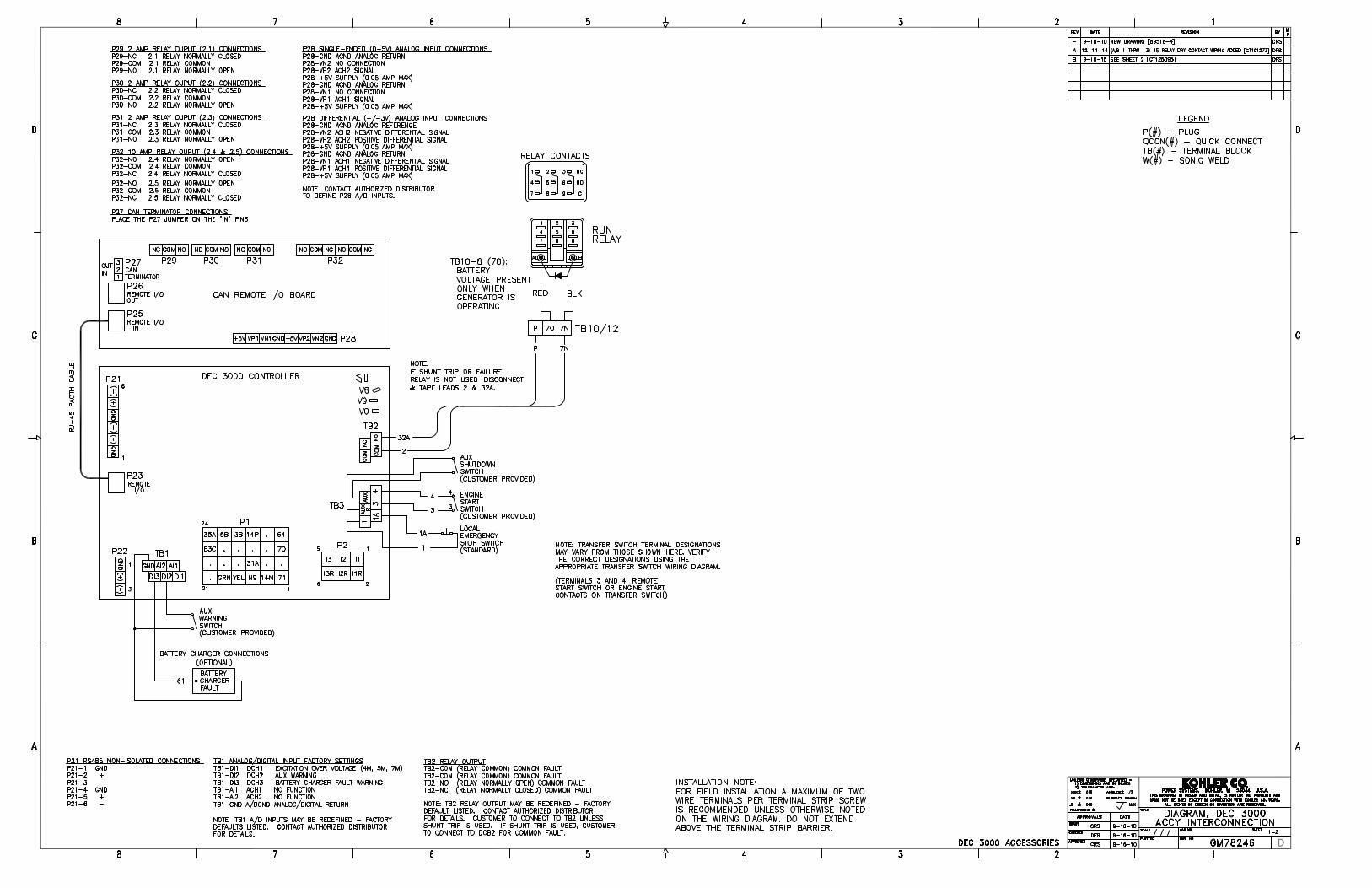
HD, HG, HJ, HL MOLDED CASE CIRCUIT BREAKERSCHARACTERISTIC TRIP CURVE NO. 50-2
CIRCUIT BREAKER INFORMATION
Circuit Breaker Continuous Maximum NumberPrefix Ampere Rating AC Voltage of Poles
HD, HG, HJ, HL 40–60 600 2, 3
This curve is to be used for application and coordination purposes only. TheEZ-AMP overlay feature at the bottom of the page should be used duringcoordination studies.
All time/current characteristic curve data is based on 40°C ambient cold start.Terminations are made with conductors of appropriate length and ratings.
Curve No. 0050TC0402June 2004
Drawing No. 48095-050-02
TM
© 2004 Schneider Electric All Rights Reserved


Integral Voltage Regulator with Kohler® Decision-Maker® 3000 and Menu-Driven Selections (15-1000kW Generator Set Models)
The voltage regulator is integral to the controller and uses patentedhybrid voltae regulator design providing ±0.5% no-load to full-loadregulation using root-mean-square (RMS) voltage sensing. The voltageregulator features three-phase sensing and is available for 12- or 24-volt engine electrical systems.
Voltage Regulators The following information provides general features, specifications, andfunctions of available voltage regulators. This information generally applies to a single generator set and multiplegenerator sets with paralleling applications. Refer to the respectivegenerator set specification sheet and see your authorized distributor forinformation regarding specific voltage regulator applications andavailability.
Integral Voltage Regulators with Decision-Maker® 3000 Controllers Calibration Digital Display Range Settings Default Selection
Voltage Adjustment Volt Adj ±10% of System Voltage System Voltage
Underfrequency Unload orFrequency Setpoint
Frequency Setpoint 42 to 62 Hz 2.5 Hz Below Nominal Frequency
Underfrequency Unload Scope Slope 0-10% of System Voltage (Voltsper Cycle)
5% of System Voltage
Industrial Generator Set Accessories Voltage Regulators

Specification/Feature Integral with Decision-Maker®
3000
Generator Set Availability 15-1000 kW
Type Patented Hybrid Design
Status and Shutdown Indicators LEDs and Text LCD Display
Operating Temperature -40°C to 70°C (-40°F to 158°F)
Storage Temperature -40°C to 85°C (-40°F to 185°F)
Humidity 5-95% Non-Condensing
Circuit Protection Solid-State, Redundant Softwareand Fuses
Sensing, Nominal 100-240 Volts (L-L), 50-60 Hz
Sensing Mode RMS, Single- or 3-Phase
Input Requirements 8-36 VDC
Continuous Output 5 VDC @ 100mA max.5.0 ADC with GM88453Activator Board
Maximum Output 5 VDC @ 100mA max.7.8 ADC with GM88453Activator Board
Transition Frequency 42.0-62.0Hz
Exciter Field Resistance 4-30 Ohms with GM88453Activator Board
No-Load to Full-Load VoltageRegulation
±0.5%
Thermal Drift <0.5% (-40°C to 70°C) [-40°F to158°F] Range
Response Time Less than 5µS
System Voltage Adjust. ±10%
Voltage Adjustment Controller Menu Knob
Remote Voltage Adjustment not available
Paralleling Capability not available
VAR/PF Control Input not available
Integral Voltage Regulator with Decision-Maker®3000 Controller• The Decision-Maker® 3000 digital display and pushbutton/rotary
dial provide access to data. A two-line LCD display providescomplete and concise information. A two-line vacuum fluorescentdisplay provides complete and concise information.
• The Decision-Maker® 3000 graphical display and pushbutton/rotarydial provide access to data. A five-line, 35-characters per line LCDdisplay provides complete and concise information include gain,ramp rate, reactive droop, VAR control (P, I, D gains) and PFcontrol (P, I, D gains).
• The controllers provide ISO 8528-5, Class G3, compliance fortransient response on some 20-300 kW generator set models. Bothcontrollers support Modbus®.
• These controllers can control Fast ResponseTM II, Fast ResponseTM
X, and wound field alternators using the GM88453 activator board.
Voltage Regulator Menu
• Voltage adjustment, ±10% of system voltage
• V/Hz cut-in, 42-62 Hz
• Underfrequency unload slope, 0-10% of system voltage
Generator Set Calibration Menu
• L1-L2 volts
• L2-L3 volts (3-phase)
• L3-L1 volts (3-phase)
• L1-N volts
• L2-N volts
• L3-N volts (3-phase)
Industrial Generator Set Accessories Voltage Regulators

Activator Board GM88453
• Interfaces between the controller and alternator assembly usingrotor field leads, auxiliary power windings, and optic board leads.
• Allows the Decision-Maker® controllers the ability to control awound-field alternator using the same control signal as FastResponseTM alternator.
• Permits the generator set controller to control the current to theexciter field of a wound-field excited alternator.
• Contains two isolated relay driver outputs (RDO) rated at 250 mA.Provides RDO outputs indicating a field over-excitation conditionand that the alternator is supplying voltage to the activator.
Modbus® is a registered trademark of Schneider Electric.
Industrial Generator Set Accessories Voltage Regulators

Alternator Data


3TIB-102 4P8 60 Hz 10/12r
4P8, 60 Hz, Low Wye or Delta ConnectionSHORT CIRCUIT DECREMENT CURVE
Time,Seconds
Armature Current, Amps*
Alternator Damage Curve
Line-to-Line 1 Phase Line-to-Neutral 1 Phase
3 Phase Symmetrical
* Instantaneous current (t=0) is asymmetric. Divide by 1.732 for symmetric.

TIB-1024 4P8 60 Hz 10/12r
4P8, 60 Hz, High Wye ConnectionSHORT CIRCUIT DECREMENT CURVE
Time,Seconds
Armature Current, Amps*
Alternator Damage Curve
Line-to-Line 1 Phase Line-to-Neutral 1 Phase
3 Phase Symmetrical
* Instantaneous current (t=0) is asymmetric. Divide by 1.732 for symmetric.

5TIB-102 4P8 60 Hz 10/12r
4P8, 60 Hz, 600 V ConnectionSHORT CIRCUIT DECREMENT CURVE
Time,Seconds
Armature Current, Amps*
Alternator Damage Curve
Line-to-Line 1 Phase Line-to-Neutral 1 Phase
3 Phase Symmetrical
* Instantaneous current (t=0) is asymmetric. Divide by 1.732 for symmetric.

Typical Overall Dimensions
Standard Features• Kohler Co. selects batteries to meet the engine manufacturer's
specifications and to comply with NFPA requirements for engine-cranking cycles.
• Heavy-duty starting batteries are the most cost-effective means ofengine cranking and provide excellent reliability in generator setapplications.
• Batteries are rated according to SAE standard J-537. All batteriesare 12-volt and have lead-calcium or lead-antimony plates withsulfuric acid electrolyte.
• Most generator set battery kits offer dry-charged or wet-chargedbatteries.
• Tough polypropylene cases protect against life-shortening vibrationand impact damage.
• Removable cell covers allow checking of electrolyte specificgravity.
Battery SAE Dimension,
mm (in.)
ChargeType*
BatteryPart
Number
BatteryQty. per
Size
BCIGroupSize
L W H Cold CrankingAmps at 18ºC
(0ºF) Min.
Reserve CapacityMinutes at
27º (80ºF) Min.
Battery PostLayout and
Style
Wet 256984 1 24 273.0(10.8)
173.0(6.8)
228.6(9.0)
650 130 C/1
Battery Specifications
Industrial Generator Set AccessoriesSystem Batteries
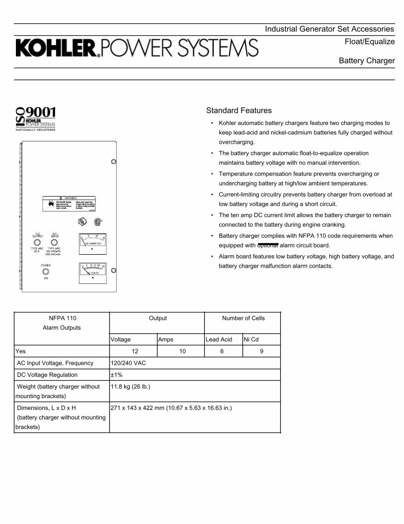
Standard Features• Kohler automatic battery chargers feature two charging modes to
keep lead-acid and nickel-cadmium batteries fully charged withoutovercharging.
• The battery charger automatic float-to-equalize operationmaintains battery voltage with no manual intervention.
• Temperature compensation feature prevents overcharging orundercharging battery at high/low ambient temperatures.
• Current-limiting circuitry prevents battery charger from overload atlow battery voltage and during a short circuit.
• The ten amp DC current limit allows the battery charger to remainconnected to the battery during engine cranking.
• Battery charger complies with NFPA 110 code requirements whenequipped with optional alarm circuit board.
• Alarm board features low battery voltage, high battery voltage, andbattery charger malfunction alarm contacts.
NFPA 110Alarm Outputs
Output
Number of Cells
Voltage Amps Lead Acid Ni Cd
Yes 12 10 6 9
AC Input Voltage, Frequency 120/240 VAC
DC Voltage Regulation ±1%
Weight (battery charger withoutmounting brackets)
11.8 kg (26 lb.)
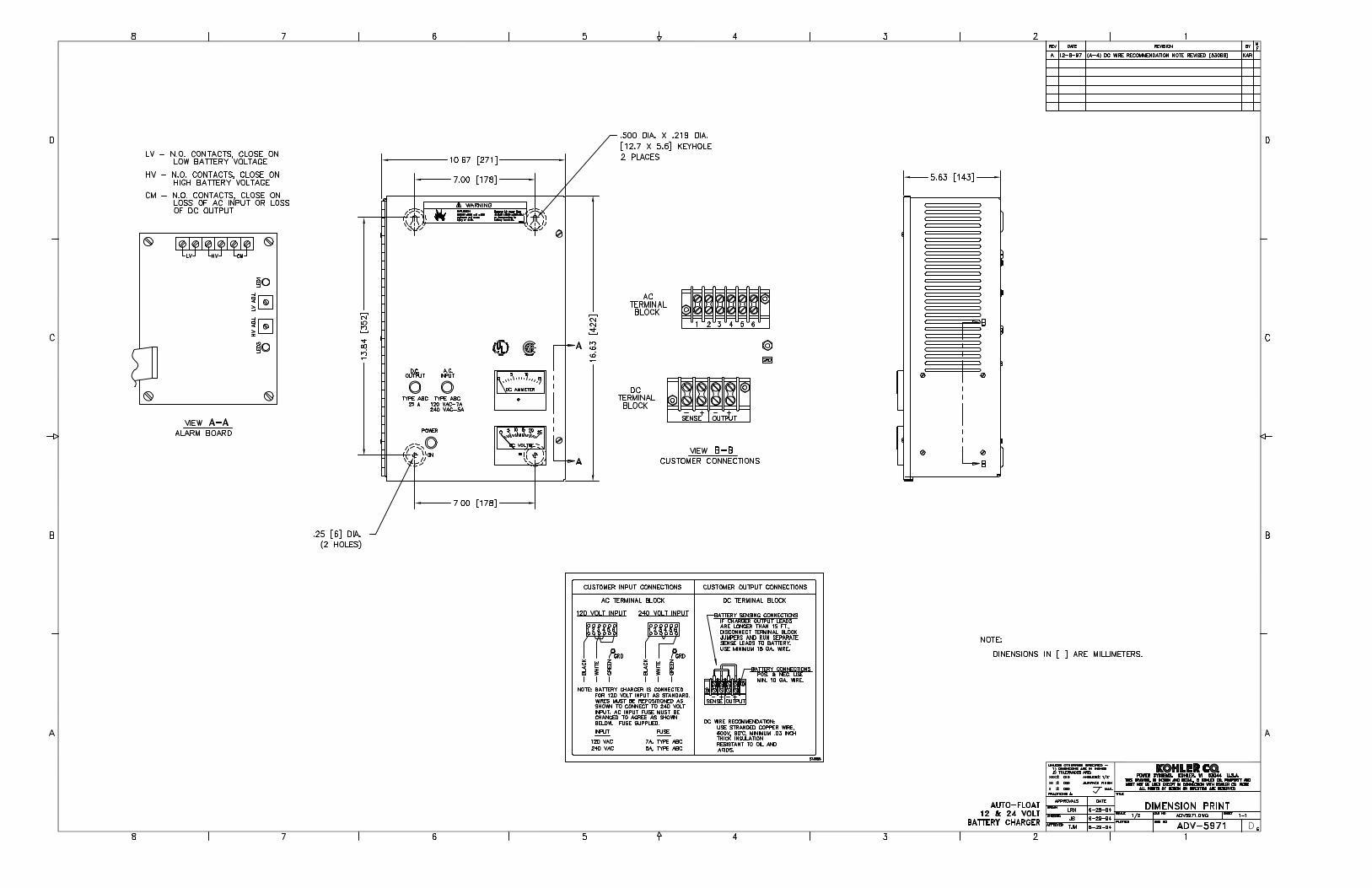
Dimensions, L x D x H (battery charger without mountingbrackets)
271 x 143 x 422 mm (10.67 x 5.63 x 16.63 in.)
Industrial Generator Set AccessoriesFloat/Equalize
Battery Charger

Automatic Float to Equalize
When the battery loses its charge, the battery charger operates in theHigh Rate Constant Current Mode until the battery voltage rises to thepreset equalize level. At the preset equalize level, the battery charger switches to theconstant voltage Equalize Mode until the current required to maintainthis voltage drops to 50% of the battery charger's high rate current. The battery charger then switches to the lower constant voltage FloatMode when the battery nears full charge. The battery charger continuesto operate in this mode until AC input power disconnects or the currentrequired to maintain the battery at the float voltage setting exceeds 6amps.
Temperature CompensationThe battery charger compensates for battery temperature using anegative temperature coefficient. The battery charger providestemperature compensation of -2mv/°C per cell over the ambienttemperature range of -40°C up to 60°C. The temperature compensationautomatically adjusts the float and equalize voltage settings to preventthe battery from overcharging at high ambient temperatures andundercharging at low ambient temperatures.
Float/Equalize Battery Charger, continued

Standard Features• Ammeter and voltmeter indicate battery charging rate with 5% full-scale accuracy. POWER ON lamp indicates battery charger is
operating.• AC input and DC output fuses prevent battery charger damage from abnormal overlaod and short-circuit conditions.• Operational temperature range is from 40°C (-40°F) to 60°C (140°F). Battery charger float equalize voltage automatically adjust
throughout the temperature range.• Reverse polarity protection circuitry prevents battery charger from energizing if improperly connected.• Internal terminal blocks for AC input and DC output/ sensing lead connections.• DC voltage regulation of ±1% from no load to full load and AC input line voltage variations of ±10%.• UL-1012 listed/CSA certified.• Wall-mount, slotted enclosure with knockouts for customer conduit installation.• Reconnection blocks allow operation at 120 or 240 volts AC, single phase, 50 or 60 hertz.• Battery charger circuitry protected from AC line and DC load voltage spikes and transients.• Terminal block for remote battery sensing leads.• Automatic float-to-equalize operation with individual potentiometer adjustments. Charge up to 12 lead-acid or 18 nickel-cadmium
battery cells.• No adjustments are necessary for lead-acid or nickel-cadmium batteries.• Oversized transformer and SCR heatsink allow constant current charging at 10 amps up to the equalize voltage setting for fastest
battery charging.Note: The battery charger will discharge the engine starting battery(ies) when the battery charger is connected to thebattery(ies) and is not connected to an AC power supply. To prevent engine starting battery(ies) discharge, install batterycharger relay kit GM39659.
Float/Equalize Battery Charger, continued

Float/Equalize Battery Charger, continued


Sound Data

TIB-114 145REZG 60 Hz 11/12a
TIB-114
TECHNICAL INFORMATION BULLETIN
Generator Set Sound Data SheetSound Pressure Data in dB(A)
GeneratorSet Model Hz Load Raw Exhaust
Open Unit,Isolated Exhaust
WeatherEnclosure
SoundEnclosure
45REZG 60100% Load 112.7 78.2 76.3 65.7
No Load 101.1 77.2 75.3 64.6
Note: Sound pressure data is the logarithmic average of eight perimeter measurement points at a distance of 7 m (23 ft.),except Raw Exhaust data which is a single measurement point at 1 m (3.3 ft.) from the mouth of a straight pipe exhaust.
45REZG 60 HzSound Pressure Levels dB(A)
Load Distance,m (ft.) Enclosure Measurement
Position Overall Level
100%Load 7 (23) Sound
Right 65.0Front--Right 67.8
Front 65.5Front--Left 67.1
Left 65.7Back--Left 65.4Back 63.7
Back--Right 64.2
8--pos. log avg. 65.7
Sound Pressure Levels dB(A)
Load Distance,m (ft.) Enclosure Measurement
Position Right Front--Right Front Front--
Left Left Back--Left Back Back--
Right8--pos.log avg.
100%Load 7 (23) Weather Overall Levels 74.7 76.7 77.5 78.9 76.2 75.7 72.8 75.1 76.3
Sound Pressure Levels dB(A)
Load Distance,m (ft.)
MeasurementPosition
Octave Band Center Frequency (Hz) OverallLevel63 125 250 500 1000 2000 4000 8000
100%Load 7 (23)
Open Unit,IsolatedExhaust
Right 44.4 58.2 68.6 70.0 70.5 70.2 66.5 60.4 76.6Front--Right 42.6 54.4 64.3 69.2 76.1 70.2 69.1 62.1 78.6
Front 55.2 63.5 69.5 72.4 74.1 72.7 70.5 64.4 79.4Front--Left 58.7 70.1 68.4 70.0 73.9 75.6 73.8 68.3 80.8
Left 59.5 67.2 68.7 69.6 71.3 71.8 69.3 66.6 78.1Back--Left 54.8 61.3 69.5 69.7 71.3 71.5 68.9 63.7 77.6Back 47.1 56.8 66.4 69.4 68.7 67.8 62.6 57.3 74.7
Back--Right 45.7 57.0 65.3 70.8 71.8 70.8 67.3 60.8 77.0
8--pos. log avg. 54.8 64.2 67.9 70.3 72.8 71.9 69.5 64.2 78.2
Sound Pressure LevelsdB(A)
Load Distance,m (ft.) Exhaust
Octave Band Center Frequency (Hz) OverallLevel63 125 250 500 1000 2000 4000 8000
100%Load 1 (3.3) Raw Exhaust (No Silencer) 90.0 94.7 107.4 103.6 102.0 105.1 105.5 102.8 112.7

TIB-1142 45REZG 60 Hz 11/12a
45REZG 60 Hz
Sound Pressure Levels dB(A)
Load Distance,m (ft.)
Enclosure MeasurementPosition
Overall Level
NoLoad 7 (23) Sound
Right 63.0Front--Right 66.8
Front 63.9Front--Left 65.4
Left 65.1Back--Left 65.5Back 61.2
Back--Right 63.8
8--pos. log avg. 64.6
Sound Pressure Levels dB(A)
Load Distance,m (ft.) Enclosure Measurement
Position Right Front--Right Front Front--
Left Left Back--Left Back Back--
Right8--pos.log avg.
NoLoad
7 (23) Weather Overall Levels 73.5 76.1 76.7 78.1 74.4 74.2 71.1 74.5 75.3
Sound Pressure Levels dB(A)
Load Distance,m (ft.)
MeasurementPosition
Octave Band Center Frequency (Hz) OverallLevel63 125 250 500 1000 2000 4000 8000
NoLoad 7 (23)
Open Unit,IsolatedExhaust
Right 37.2 57.0 63.7 68.5 70.0 70.1 65.5 58.1 75.4Front--Right 39.4 51.6 58.6 68.5 75.6 69.6 68.7 60.8 78.0
Front 47.0 60.0 65.0 72.2 74.1 72.3 69.5 60.1 78.6Front--Left 51.7 63.5 67.7 70.2 73.7 75.4 73.1 65.1 80.0
Left 46.5 57.5 64.9 69.1 70.7 71.1 66.8 59.6 76.3Back--Left 40.9 50.7 62.7 69.5 70.6 71.0 66.6 58.2 76.1Back 43.9 52.2 61.5 67.6 67.8 67.0 61.1 52.0 73.0
Back--Right 41.6 54.8 61.7 70.2 71.5 70.6 66.7 59.2 76.4
8--pos. log avg. 45.9 58.0 64.0 69.7 72.4 71.5 68.4 60.3 77.2
Sound Pressure Levels dB(A)
LoadDistance,
(ft.) ExhaustOctave Band Center Frequency (Hz) Overall
Level63 125 250 500 1000 2000 4000 8000
NoLoad 1 (1.1) Raw Exhaust (No Silencer) 71.1 83.4 98.9 95.2 89.6 86.6 82.9 76.6 101.1

Emissions Data

Engine Speed Freq Fuel Duty Cycle Engine Family C02 THC+NOx CO bsfc5 Catalyst RPM Hz HP kW (g/KW-hr) (g/KW-hr) (g/kW-hr) (g/kW-hr)
4.3L 1800 60 LP Emergency 71.4 53.2 GPSIB4.302ED 873.7 8.17 32.02 234.1 No 4.3L 1800 60 NG Emergency 66.5 49.6 GPSIB4.302ED 713.29 7.03 21.96 225.7 No
4.3L 1800 60 LP Prime 71.4 53.2GPSIB4.30GLP
800.96 0.07 0.59 Yes
4.3L 1800 60 NG Prime 66.5 49.6GPSIB4.30GLP
824.88 0.92 0.36 Yes
1
2
3
4
5
PSI 2016 Stationary 60 Hz Emergency Standby1 and Prime Certified Power Generation Rating DataGenerator Model Flywheel power 2,3
All ratings are gross flywheel horsepower corrected to 77ºF at an altitude of 328 feet with no cooling fan or alternator losses using heating value for NG of 1015 BTU/SCF.
Production tolerances in engines and installed components can account for power variations of +/- 5%. Altitude, temperature and excessive exhaust and intake restrictions should be applied to power calculations.
Electrical ratings are an estimated based on assumed fan and generator losses and may vary depending on actual equipment losses.
Bsfc is based on 100% gross flywheel power rating and does not include fan or generator losses.
Standby and overload ratings based on ISO3046. Continuous ratings based on ISO 8528.
45REZG
630.350.9400 (Main) – 630.350.9900 (Fax)www.psiengines.com [email protected]
For additional questions contact:Power Solutions International, Inc.
201 Mittel Drive, Wood Dale, IL 60191

Warranty

To obtain warranty service, call 1-800-544-2444 for your nearest authorized Kohler service representative or write Kohler Co., KohlerPower Systems Service Department, MS072, Kohler, WI 53044 USA.
KOHLER CO. SHALL NOT BE LIABLE FOR SPECIAL, INCIDENTAL, AND/OR CONSEQUENTIAL DAMAGES OF ANY KINDincluding, but not limited to, incidental and/or consequential labor costs, installation charges, telephone charges, ortransportation charges in connection with the replacement or repair of defective parts.
This is our exclusive written warranty. We make no other express warranty nor is anyone authorized to make any on our behalf.
ANY IMPLIED OR STATUTORY WARRANTY, INCLUDING ANY WARRANTY OF MERCHANTABILITY OR FITNESS FOR APARTICULAR PURPOSE, IS EXPRESSLY LIMITED TO THE DURATION OF THIS WARRANTY. Some states do not allowlimitations on how long an impliedwarranty lasts, or the exclusion or limitation of incidental and/or consequential damages,so the above limitation or exclusion may not apply to you.
This warranty gives you specific legal rights, and you may also have other rights which vary from state to state.
TP-5561 8/13d
Stationary Standby Industrial Generator SetExtended Five-Year or Three Thousand (3000)-Hour
Comprehensive Limited WarrantyYour Kohler product has been manufactured and inspected with care by experienced craftsmen. If you are the original end user,Kohler Co.warrants, for theperiod indicatedbelow,eachproduct tobe free fromdefects inmaterials andworkmanship. In theeventofadefect inmaterials orworkmanship,KohlerCo.will repair, replace, ormakeappropriateadjustment atKohler Co.’s option if theproduct,upon Kohler Co.’s inspection, is found to be properly installed, maintained, and operated in accordance with Kohler Co.’s instructionmanuals. A Kohler distributor, dealer, or authorized service representative must perform startup.
Kohler Product Warranty Coverage
Stationary Standby Generator Set & Accessories Five (5) years from registered startup or three thousand (3000) hours(whichever occurs first).
This warranty is not effective unless a proper extended warranty registration form and warranty fee have been sent toKohler Co. within one year of registered startup. The extended warranty start date is determined by the standard warrantyrequirements and runs concurrent with the standard warranty during the first year. To receive extended warranty coverage, theprovisions of the standard warranty registration must be met.
KOHLER CO. Kohler, Wisconsin 53044Phone 920-457-4441, Fax 920-459-1646For the nearest sales/service outlet in theUS and Canada, phone 1-800-544-2444KOHLERPower.com
The following will not be covered by the warranty:
1. Normal engine wear, routine tuneups, tuneup parts,adjustments, and periodic service.
2. Damage caused by accidents, improper installation orhandling, faulty repairs not performed by an authorizedKohler service representative, or improper storage.
3. Damage caused by operation with improper fuel or atspeeds, loads, conditions, modifications, or installationcontrary to published specifications or recommendations.
4. Damage caused by negligent maintenance such as:
a. Failure to provide the specified type and sufficientquantity of lubricating oil.
b. Failure to keep the air intake and cooling fin areas clean.c. Failure to service the air cleaner.d. Failure to provide sufficient coolant and/or cooling air.e. Failure to perform scheduled maintenance as
prescribed in supplied manuals.f. Failure to regularly exercise thegeneratorsetunder load
(stationary applications only).
5. Original installation charges and startup costs.
6. Starting batteries and the following related expenses:
a. Labor charges related to battery service.b. Travel expense related to battery service.
7. Engine coolant heaters, heater controls, and circulatingpumps after the first year.
8. Additional expenses for repair after normal businesshours, i.e. overtime or holiday labor rates.
9. Rental of equipment during performance of warrantyrepairs.
10. Removal and replacement of non-Kohler-suppliedoptions and equipment.
11. Replacement of a failed Kohler part with a non-Kohlerpart voids the warranty on that part.
12. Radiators replaced rather than repaired.
13. Fuel injection pumps not repaired by an authorizedKohler service representative.
14. Non-Kohler-authorized repair shop labor without priorapproval from Kohler Co. Warranty Department.
15. Engine fluids such as fuel, oil, or coolant/antifreeze.
16. Shop supplies such as adhesives, cleaning solvents,and rags.
17. Expenses incurred investigating performancecomplaints unless the problem is caused by defectiveKohler materials or workmanship.
18. Maintenance items such as fuses, lamps, filters, sparkplugs, loose or leaking clamps, and adjustments.
19. Travel time and mileage exceeding 300miles round trip.

Automatic Transfer Switches

Transfer Switch Standard Features• UL 1008 listed at 480 VAC file #E58962 (automatic), #E86894
(non automatic)• CSA certification available at 600 VAC• IBC seismic certification available• Available in 2, 3, or 4 pole configurations• Electrically operated, mechanically held mechanism• High withstand and close-on ratings• Design suitable for emergency and standby applications on all
classes of load, 100% tungsten rated through 400 amps• Silver alloy main contacts• Gold-flashed engine start contacts rated 2 amps @ 30 VDC/250
VAC• Front-accessible contacts for easy inspection• Front-replaceable main and arcing contacts (800-4000 amps)• Reliable, field-proven solenoid mechanism• Switching mechanisms lubricated for the expected life of the
transfer switch• Internal manual operating handle• Main shaft auxiliary position-indicating contacts rated 10 amps @
32 VDC/250 VAC• NEMA type 1, 12, 3R, 4, and 4X enclosures available• Standard one-year limited warranty. Extended limited warranties
are available
Programmed-Transition Models (KCP)• Programmed-transition operation with either automatic or non-
automatic control • Programmed-transition operation provides a center OFF position
that allows residual voltages in the load circuits to decay • Programmable OFF time • Double-throw, mechanically interlocked design (break-before-
make power contacts) • Solid or switched neutral
Model KCP-ANTB-0225S

Decision-Maker® MPAC 1200 Controller
• LCD display, 4 lines x 20 characters, backlit• Complete programming and viewing capability at the door using
the keypad and LCD display• LED indicators: Source available, transfer switch position,
service required (fault), and "not in auto"• Programmable voltage and frequency pickup and dropout
settings• Programmable time delays• Programmable generator exerciser• Time-based load control• Two programmable inputs and two programmable outputs• Up to four I/O extension modules available• Modbus communication standard• RS-485 communication standard• Ethernet communication optional For
more information about Decision-Maker® MPAC 1200 featuresand functions, see sepcification sheet G11-127
Environmental Specifications
Operating Temperature -20°C to 70°C (-4°F to 158°F)
Storage Temperature -40°C to 85°C (-40°F to 185°F)
Humidity 5% to 95% noncondensing
Input and Output Connection Specifications
Component Wire Size Range
Main board I/O terminals #12-24 AWG
I/O module terminals #14-24 AWG
Auxiliary Position Indication Contacts(rated 10 Amps @ 32 VDC/250 VAC)
Switch Rating, amps Number of Contacts Indicating Normal,Emergency
225 8, 8
Model KCP-ANTB-0225S, continued
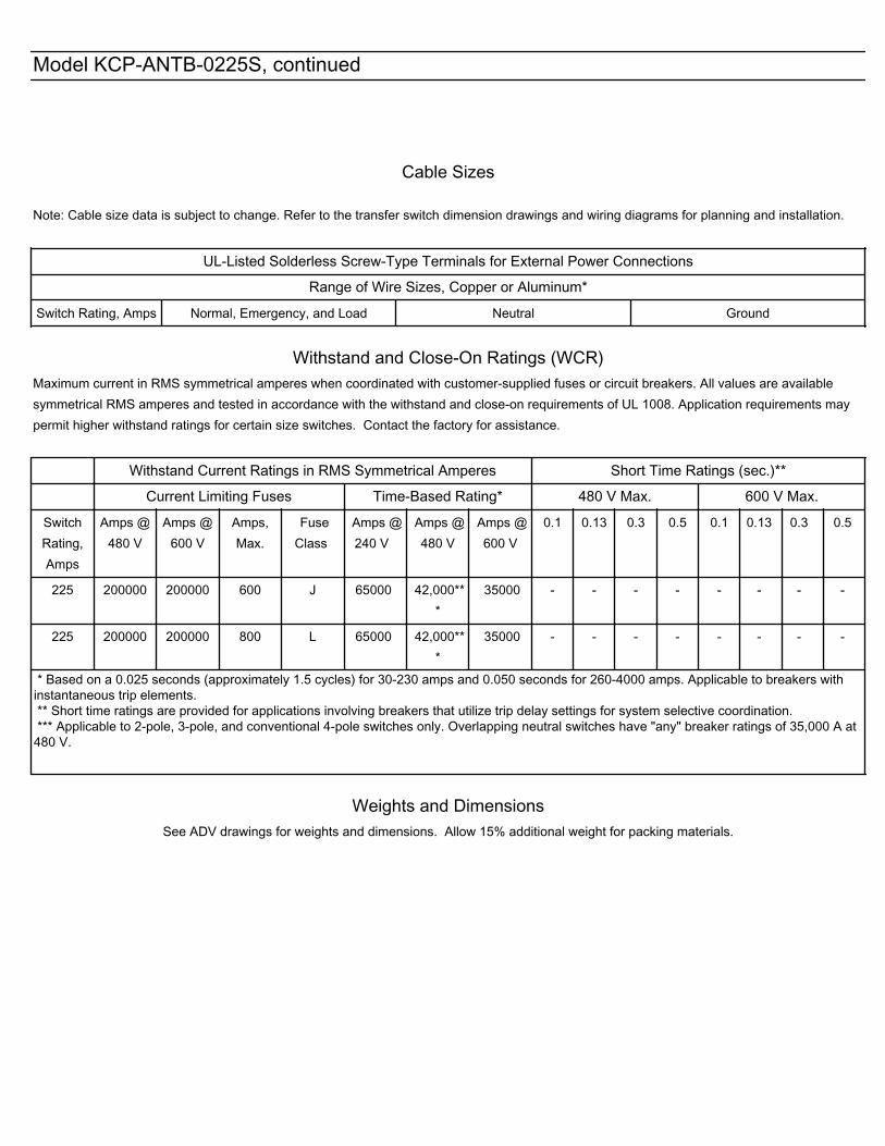
Cable Sizes
Note: Cable size data is subject to change. Refer to the transfer switch dimension drawings and wiring diagrams for planning and installation.
UL-Listed Solderless Screw-Type Terminals for External Power Connections
Range of Wire Sizes, Copper or Aluminum*
Switch Rating, Amps Normal, Emergency, and Load Neutral Ground
Withstand and Close-On Ratings (WCR)
Maximum current in RMS symmetrical amperes when coordinated with customer-supplied fuses or circuit breakers. All values are availablesymmetrical RMS amperes and tested in accordance with the withstand and close-on requirements of UL 1008. Application requirements maypermit higher withstand ratings for certain size switches. Contact the factory for assistance. Withstand Current Ratings in RMS Symmetrical Amperes Short Time Ratings (sec.)**
Current Limiting Fuses Time-Based Rating* 480 V Max. 600 V Max.
SwitchRating,Amps
Amps @480 V
Amps @600 V
Amps,Max.
FuseClass
Amps @240 V
Amps @480 V
Amps @600 V
0.1 0.13 0.3 0.5 0.1 0.13 0.3 0.5
225 200000 200000 600 J 65000 42,000***
35000 - - - - - - - -
225 200000 200000 800 L 65000 42,000***
35000 - - - - - - - -
* Based on a 0.025 seconds (approximately 1.5 cycles) for 30-230 amps and 0.050 seconds for 260-4000 amps. Applicable to breakers withinstantaneous trip elements. ** Short time ratings are provided for applications involving breakers that utilize trip delay settings for system selective coordination. *** Applicable to 2-pole, 3-pole, and conventional 4-pole switches only. Overlapping neutral switches have "any" breaker ratings of 35,000 A at480 V.
Weights and Dimensions
See ADV drawings for weights and dimensions. Allow 15% additional weight for packing materials.
Model KCP-ANTB-0225S, continued

Ratings with Specific Manufacturer's Circuit BreakerThe following charts list power switching device withstand and close-on ratings (WCR) in RMS symmetrical amperes for specific manufacturers'circuit breakers. Circuit breakers are supplied by the customer.
Molded-Case Circuit Breakers
Switch Rating,Amps
WCR, Amps, RMS Voltage, Max. Manufacturer Type Max. Size, Amps
225 50000 480 Eaton HJD, JDC, JGH, JGC 250
225 50000 480 Eaton HKD, CHKD, KDC 400
225 50000 480 Eaton HLD, CHLD, LDC, CLDC 600
225 50000 480 Eaton MDL, CMDL, HMDL, CHMDL, NGS, NGH,NGC
800
225 50000 480 GE SFL, SFP 250
225 50000 480 GE TBC4 600
225 50000 480 GE SGL1, SGL4, SGL6, SGP1, SGP4, SGP6,TBC6, TJL4V, TJL1S-6S
600
225 50000 480 GE SKL8, SKP8, SKH8, TBC8, TKL4V,TKH8S-12S
800
225 50000 480 Siemens/ITE HFD, HFXD 250
225 50000 480 Siemens/ITE HJD, HJXD, SHJD 400
225 50000 480 Siemens/ITE HLD 600
225 50000 480 Siemens/ITE HLMD, HLMXD, HMG, HMD, HMXD, LMD,LMXD, MXD, SMD, SHMD
800
225 50000 480 SquareD KC 250
225 50000 480 SquareD CK400N, CK400NN 400
225 50000 480 SquareD LC 600
225 50000 480 SquareD CK800N, CK800NN 800
225 42000 600 Eaton JGC 250
225 42000 600 Eaton KDC 400
225 42000 600 Eaton LDC, CLDC 600
225 42000 600 GE TBC4 400
225 42000 600 GE TBC6, SGL1, SGL4, SGL6, SGP1, SGP4,SGP6
600
225 42000 600 GE TBC8, TKL4V, TKL8S-12S, SKL8, SKP8 800
225 42000 600 Siemens/ITE HLMD, HLMXD, HMXD, SHMD 800
Model KCP-ANTB-0225S, continued

Codes and Standards
The ATS meets or exceeds the requirements of the followingspecifications: • CSA C22.2 No. 178 certification 208-600 VAC available, file
LR58301• EN61000-4-4 Fast Transient Immunity Severity Level 4• EN61000-4-5 Surge Immunity Class 4 (voltage sensing and
programmable inputs only)• EIC Spedifications for EMI/EMC Immunity:
o CISPR 11, Radiated Emissions
o IEC 1000–4–2, Electrostatic Discharge
o IEC 1000–4–3, Radiated Electromagnetic Fields
o IEC 1000–4–4, Electrical Fast Transients (Bursts)
o IEC 1000–4–5, Surge Voltage
o IEC 1000–4–6, Conducted RF Disturbances
o IEC 1000–4–8, Magnetic Fields
o IEC 1000–4–11, Voltage Dips and Interruptions
• IEC 609047-6-1, Low Voltage Switchgear and Control Gear;Multifunction Equipment; Automatic Transfer SwitchingEquipment
• IEEE Standard 446, IEEE Recommended Practice forEmergency and Standby Power Systems for Commercial andIndustrial Applications
• IEEE 472 (ANSI C37.90A) Ring Wave Test• NEMA Standards ICS 10-2005, Electromechanical AC Transfer
Switch Equipment• NFPA 70, National Electrical Code• NFPA 99, Essential Electrical Systems for Health Care Facilities• NFPA 110, Emergency and Standby Power Systems• Seismic certification in accordance with the International
Building Code is available. (Accessory kit is required for seismiccertification)
o IBC 2000, referencing ASCE 7-98 and ICC AC-156
o IBC 2003, referencing ASCE 7-02 and ICC AC-156
o IBC 2006, referencing ASCE 7-05 and ICC AC-156
o IBC 2009, referencing ASCE 7-05 and ICC AC-156
o IBC 2012, referencing ASCE 7-10 and ICC AC-156
• Underwriters Laboratories UL 1008, Standard for AutomaticTransfer Switches for Use in Emergency Standby Systems for#E58962 (automatic), #E86894 (nonautomatic)
Model KCP-ANTB-0225S, continued

CSA Certification
Current Sensing Kit • Monitor current on all phases with 1% accuracy
Neutral Assembly
• Available as loose kit for open units
Line-to-Neutral Voltage Monitoring • Monitors all line–to–neutral voltages
Warranty
KCP-ANTB-0225S , continued
Accessories
Accessories are available either factory-installed or as loose kits, unless otherwise noted.
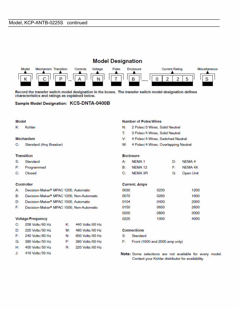
Model, KCP-ANTB-0225S continued
K C P A N T B 0 2 2 5 S

Decision-Makerr MPAC 1200
Automatic Transfer Switch Controller
Model KCS with Decision-Makerr MPAC 1200 Controller
G11-127 (MPAC 1200) 3/14 Page 1
Applicable Models
Model Description
KCS Standard-Transition Any Breaker ATS ]
KCP Programmed-Transition Any Breaker ATS ]
KCC Closed-Transition Any Breaker ATS w
KSS Standard-Transition Specific Breaker ATS ]
KSP Programmed-Transition Specific Breaker ATS ]
] Available with automatic or non-automatic controllerw Available with automatic controller only
Decision-Makerr MPAC 1200 ControllerStandard FeaturesD Microprocessor-based controllerD Environmentally sealed user interfaceD LCD display, 4 lines x 20 characters, backlitD Dynamic function keypad with tactile feedback pushbuttonsallows complete programming and viewing capability at thedoor
D LED indicators: Source available, transfer switch position,service required (fault), and not in auto
D Broadrange voltage sensing (208--600 VAC) on all phasesD Phase-to-phase sensing and monitoring with 0.5% accuracyon both sources
D Frequency sensing with 0.5% accuracy on both sourcesD Anti-single phasing protectionD Phase rotation sensing for three-phase systemsD Real-time clock with automatic adjust for daylight saving timeand leap year
D Run time clock and operation counterD Time-stamped event logD Fail-safe transfer for loaded test and exercise functionsD DIP switches: password disable and maintenanceD Isolated RS-485 ports for Modbus connections(9.6, 19.2, and 57.6 kbps)
D Modbusr RTU protocol (Modbus register map available)D USB port. Connect a personal computer and use KohlerrSiteTecht software to view events and adjust settings. *
D Available in automatic and non-automatic versions; seesupervised transfer control switch on page 5
Programmable FeaturesD Programming and monitoring methods:d Monitoring and password-protected programming at thedoor using the keypad and display
d Program using a PC with Kohlerr SiteTecht software(available to Kohler-authorized distributors and dealers)
D Over/undervoltage for all phases of the normal andemergency sources
D Over/underfrequency for the emergency sourceD Adjustable time delaysD Load/no load/auto-load test and load/no-load exercisefunctions
D Programmable inputs and outputsD Load bank control for exercise or testD Time-based load control, nine individual time delays forselected loads
D In-phase monitor (3-phase only)D Password protection, three security levelsD See pages 2 and 3 for additional programmable features
* SiteTech software is available to Kohler-authorized distributorsand dealers.Modbus is a registered trademark of Schneider Electric.

G11-127 (MPAC 1200) 3/14 Page 2
Decision-Makerr MPAC 1200 Controller FeaturesUser Interface LED IndicatorsD Contactor position: source N and source E
D Source available: source N and source E
D Service required (fault indication)
D Not in automatic mode
LCD DisplayD System status
D Line-to-line voltage
D Line-to-neutral voltage
D Active time delays
D Source frequency
D Preferred source selection
D System settings
D Common alarms
D Load current, each phase (current sensing kit required)
D Inputs and outputs
D Faults
D Time/date
D Address
D Event history
D Maintenance records
D Exerciser schedule
D Exerciser mode
D Time remaining on active exercise
Dynamic Function Tactile Keypad OperationsD Scroll up/down/forward/back
D Increase/decrease/save settings
D End time delay
D Start/end test or exercise
D Reset fault
D Lamp test
DIP SwitchesD Maintenance mode
D Password disable
Event HistoryD View time and date-stamped events on the display or on apersonal computer equipped with Kohlerr SiteTechtsoftware. *
D Download complete event history files using Kohler SiteTechsoftware and a PC connected to the USB port. *
Main Logic Board Inputs and OutputsD Two (2) programmable inputs
D Two (2) programmable outputs
CommunicationsD Optional Ethernet communications with RJ45 connector for10/100 Ethernet connection
D Isolated RS-485 ports for Modbus communications
D Modbusr RTU and Modbusr TCP/IP protocols(Modbusr register map available)
D USB Port. Use SiteTech software to upload or downloadfiles and adjust transfer switch settings *
d Application software
d Event history files
d Language files
d Parameter settings
d Usage reports
d Feature configuration
Programmable FeaturesD System voltage, 208--600 VAC [
D System frequency, 50/60 Hz [
D Single/three-phase operation [
D Standard/programmed/closed-transition operation [
D Preferred source selection allows the normal or emergencysource to be used when both sources are available (alarmmodule required)
D Phase rotation: ABC/BAC/none selection with errordetection
D Overvoltage and undervoltage pickup and dropout settings,both sources
D Overfrequency and underfrequency pickup and dropoutsettings, Emergency source
D Voltage unbalance, enable/disable
D In-phase monitor: enable/disable and phase angle
D Transfer commit/no commit
D Passwords, system and test
D Time, date, automatic daylight saving time enable/disable
D Time delays (see table)
D Exerciser: calendar mode, loaded/unloaded up to 21 events
D Test: loaded/unloaded/auto load (1--60 minutes)
D Remote test: loaded/unloaded
D Automatic override on generator failure (loaded test andexercise)
D Peak shave delay enable/disable
D Current monitoring (current sensing kit required)D Load control pre/post-transfer delays, 9 individual timedelays for selected loads
D Resettable historical data
* SiteTech software is available to Kohler-authorized distributors and dealers.[ System parameters are factory-set per order.
Modbus is a registered trademark of Schneider Electric.

G11-127 (MPAC 1200) 3/14 Page 3
Decision-Makerr MPAC 1200 Controller Features, ContinuedProgrammable InputsD Forced transfer to OFF (programmed-transition models only;requires load shed accessory)
D Inhibit transfer
D Low battery voltage (external battery supply modulerequired)
D Peak shave/area protection input
D Remote common fault
D Remote test
D Remote end time delay
D Remotely monitored inputs, four (4) available
Programmable OutputsD Alarm silenced
D Audible alarm
D Chicago alarm control
D Common alarm events
D Contactor position
D Exercise active
D Failure to acquire standby source
D Failure to transfer
D Generator engine start, source E
D I/O module faults
D In-phase monitor synch
D Load bank control
D Load control active (pre/post transfer delay, up to 9 outputs)
D Loss of phase fault, source N and E
D Low battery fault (external battery supply module required)
D Maintenance mode
D Non-emergency transfer
D Not in automatic mode
D Over/undervoltage faults, source N and E
D Peak shave/area protection active
D Phase rotation error, source N and E
D Preferred source supplying load
D Software-controlled relay outputs (four maximum)
D Source available, preferred and standby
D Standby source supplying load
D Test active
D Transfer switch auxiliary contact fault
D Transfer switch auxiliary contact open
D Voltage unbalance, source N and E
Voltage and Frequency Sensing
Parameter DefaultAdjustment
Range
Undervoltage dropout 90% of pickup 75%--98%
Undervoltage pickup 90% of nominal 85%--100%
Overvoltage dropout * 115% of nominal* 106%--135%
Overvoltage pickup 95% of dropout 95%--100%
Unbalance enable Disable Enable/Disable
Unbalance dropout 20% 5%--20%
Unbalance pickup 10% 3%--18%
Voltage dropout time 0.5 sec. 0.1--9.9 sec.
Underfrequency dropout [ 99% of pickup 95%--99%
Underfrequency pickup [ 90% of nominal 80%--95%
Overfrequency dropout [ 101% of pickup 101%--115%
Overfrequency pickup [ 110% of nominal 105%--120%
Frequency dropout time [ 3 sec. 0.1--15 sec.
* 690 volts, maximum. Default = 110% for 600 volt applications.[ Emergency source only
Adjustable Time DelaysTime Delay Default Adjustment Range
Engine start 3 sec. 0--6 sec. [
Engine cooldown 5 min.
0--60 min.Fail to acquire standby source 1 min.
Transfer, preferred to standby 3 sec.
Transfer, standby to preferred 15 min.
Transfer, off to standby 1 sec.1 sec. -- 60 min.
Transfer, off to preferred 1 sec.
Fail to synchronize 60 sec. 10 sec -- 15 min.
Auto load test termination aftertransfer
1 sec. 1 sec.--60 min.
Load Control Time Delays:
Pretransfer to preferred 0 sec.
0--60 min.Post-transfer to preferred 0 sec.
Pretransfer to standby 0 sec.
Post-transfer to standby 0 sec.
Note: Time delays are adjustable in 1 second increments, except asnoted.
[ Enginestart timedelay canbeextended to 60 minuteswith anExternalBattery Supply Module Kit.

G11-127 (MPAC 1200) 3/14 Page 4
Accessory ModulesThe mounting kit holds up to five optional modules.
Module Current Draw Specifications, mAAlarm Module 75
Standard I/O Module 75
High Power I/O Module 100
Maximum Total Current * 300
* If an External Battery Module is installed, there is no currentrestriction.
- Standard Input/Output Module
InputsAvailable Inputs 2
Input Definition Contact closure
Current 5 mA Max
Connection Type Terminal Strip
Wire Size #14--24 AWG
Max Distance 700 feet
OutputsOutputs Available 6
Contact Type Form C (SPDT)
Contact Voltage Rating2 A @ 30 VDC500 mA @ 125 VAC
Connection Type Terminal Strip
Wire Size #14--24 AWG
- High-Power Input/Output Module
InputsAvailable Inputs 2
Input Definition Contact closure
Current 5 mA Max
Connection Type Terminal Strip
Wire Size #14--24 AWG
Max Distance 700 feet
OutputsOutputs Available 3
Contact Type Form C (SPDT)
Contact Voltage Rating
12 A @ 24 VDC12 A @ 250 VAC10 A @ 277 VAC2 A @ 480 VAC
Connection Type Terminal Strip
Wire Size #14--24 AWG
Environmental SpecificationsTemperature --40C to 85C (--40F to 185F)
Humidity 35% to 85% noncondensing
- Alarm ModuleD 90 dB Audible alarm
DAny alarm function can be programmed to trigger theaudible alarm
DChicago alarm function
DPreferred source selection
DSupervised transfer control (supervised transfer controlswitch required)
DConnection for external alarm
External Alarm Connection SpecificationsWire Size #12--22 AWG Cu
Contact Voltage Rating500 mA @ 120 VAC
250 mA @ 240 VAC
- External Battery Supply ModuleDEnergizes the ATS controls using an external batterywhen no source power is available
DAllows extended engine start time delays
DAllows the use of any combination of accessory modules(no current draw restriction, maximum of five modulestotal)
DConnects to one or two batteries, 12 VDC or 24 VDCsystem
DCurrent draw, 140 mA @ 12 VDC, 86 mA@ 24 VDC
DProvides low external battery voltage indication to thetransfer switch controller
DReverse-polarity protected

G11-127 (MPAC 1200) 3/14 Page 5
Other Controller AccessoriesAccessories are available either factory-installed or as loosekits, unless otherwise noted.
- Controller Disconnect SwitchDDisconnects power to the controller without disconnectingthe load
DMounts inside the enclosure
- Current Sensing KitDMonitor current on all phases with 1% accuracy
- Digital MeterDMeasure and display voltage, current, frequency, andpower for both sources
DProgrammable visual alarms for high voltage, low voltage,and high current
D Three digital outputsDSerial port for optional network connectionsDPassword-protected programming menusD Joystick operationD Factory-installed
- Ethernet CommunicationsDRJ-45 connectorDSupports Internet Protocol version 4 (IPv4)DSupports Modbus TCP/IP protocol
- Line-to-Neutral Voltage MonitoringDMonitors all line-to-neutral voltages
- Load Shed KitD Forced transfer from Emergency to OFF forprogrammed-transition models
DCustomer-supplied signal (contact closure) is required forthe forced transfer to OFF function
D Factory-installed only
- Padlockable User Interface CoverDProvides additional protection against unauthorizedaccess
DCover standard on NEMA 3R enclosures
- RSA III Remote Serial AnnunciatorDMonitors the generator setDMonitors ATS common alarm, Normal source, andEmergency source status and connection
DAllows remote testing of the ATSD For more information about RSA III features andfunctions, see specification sheet G6--139
- Supervised Transfer Control SwitchDStandard on models with non-automatic controls
DOptional for models with automatic controls
DAuto, manual, and transfer positions
DAutomatic and non-automatic modes
DAlarm module required
Supervised Transfer Control Switch Operation for Automatic and Non-Automatic Transfer Switches
Switch Position Automatic Switches Non-Automatic Switches
AUTO D Automatically transfers to the standby source, when available, if the preferred source is lost.
D Transfers back to the preferred source when it becomes available.
MANUAL D Automatically transfers to an available source ifthe connected source is lost.
D Test, peak shave, and loaded exercise commandswill transfer to the standby source.
D Does not automatically transfer back to preferredwhen both sources are available.
D Does not automatically transfer to an availablesource when the connected source is lost.
D Test, peak shave, and loaded exercise commandsare ignored.
D Does not automatically transfer back to preferredwhen both sources are available.
D Transfers only when the switch is manually movedto the TRANSFER position as described below.
TRANSFER(momentaryswitch position)
D Does not initiate an engine start sequence. Generator set engine must be signalled to start by an eventsuch as a loss of utility, loaded test, loaded exercise, etc.
D Allows transfer to the other source, if available. An event such as a loss of utility, loaded exercise, orloaded test must first initiate the transfer sequence.
D Time delays will operate. Wait for time delays to expire, or press the End Time Delay button.
D Operates pre- and post-transfer load control time delays if both sources are available.
D MANUAL TRANSFER is displayed when the ATS is ready to transfer.

DISTRIBUTED BY:
Kohler Power SystemsAsia Pacific Headquarters7 Jurong Pier RoadSingapore 619159Phone (65) 6264-6422, Fax (65) 6264-6455
KOHLER CO., Kohler, Wisconsin 53044 USAPhone 920-457-4441, Fax 920-459-1646For the nearest sales and service outlet in theUS and Canada, phone 1-800-544-2444KOHLERPower.com
Availability is subject to change without notice. Kohler Co. reserves theright to change the design or specifications without notice and withoutany obligation or liability whatsoever. Contact your local Kohlerr PowerSystems distributor for availability.
2014 by Kohler Co. All rights reserved.
G11-127 (MPAC 1200) 3/14 Page 6
Environmental SpecificationsOperating Temperature --20C to 70C (--4F to 158F)
Storage Temperature --40C to 85C (--40F to 185F)
Humidity 5% to 95% noncondensing
Main Board I/O SpecificationsOutput contact type Isolated form C (SPDT)
Output contact rating 1 amp @ 30 VDC, 500 mA @120VAC
I/O terminals wire size #12--24 AWG


Wiring Schematics


Warranty

Your Kohler product has been manufactured and inspected with care by experienced craftsmen. If you are the original end user,Kohler Co.warrants, for the period indicated below, each product to be free fromdefects inmaterials andworkmanship. In theevent of adefect inmaterials or workmanship, Kohler Co. will repair, replace, ormake appropriate adjustment at Kohler Co.’s option if the product,upon Kohler Co.’s inspection, is found to be properly installed, maintained, and operated in accordance with Kohler Co.’s instructionmanuals. A Kohler distributor, dealer, or authorized service representative must perform startup.
Kohler Product Warranty Coverage
Transfer switch and factory-supplied Five (5) years from registered startup date.transfer switch accessories
Transfer switch main contacts Ten (10) years from the registered startup date.
This warranty is not effective unless a proper extended warranty registration form and warranty fee have been sent toKohler Co. within one year of registered startup. The extended warranty start date is determined by the standard warrantyrequirements and runs concurrent with the standard warranty during the first year. To receive extended warranty coverage, theprovisions of the standard warranty registration must be met.
The following will not be covered by the warranty:1. Normal wear, periodic service, and routine adjustments.2. Damage, including but not limited to damage caused by
accidents, improper installation or handling, faulty repairsnot performed by an authorized Kohler servicerepresentative, improper storage, or acts of God.
3. Damage caused by:a. Operation above or below rated capacity, voltage, or
frequency.b. Modifications.c. Installation contrary to published specifications and
codes.4. Damage caused by negligent maintenance such as:
a. Failure to provide a clean, dry environment.b. Failure to perform recommended exercising.c. Failure to perform scheduled maintenance as
prescribed in supplied manuals.d. Use of parts and/or procedures other than
factory-supplied or -approved replacement partsand/or procedures.
5. Non-Kohler replacement parts. Replacement of a failedKohler part with a non-Kohler part voids the warranty onthat part.
6. Original installation charges and startup costs.7. Additional expenses for repair after normal business
hours, i.e. overtime or holiday labor rates.8. Rental of equipment during performance of warranty
repairs.9. Removal and replacement of non-Kohler-supplied
options and equipment.10. Non-Kohler-authorized repair shop labor without prior
approval from Kohler Co. Warranty Department.11. Expenses incurred investigating performance complaints
unless the problem is caused by defective Kohlermaterials or workmanship.
12. Maintenance items such as fuses, lamps, andadjustments.
13. Labor and travel charges after the fifth year of the transferswitch main contacts warranty period.
14. Travel time and mileage exceeding 300 miles round trip.
Transfer Switch Extended Five-YearComprehensive Limited Warranty
To obtain warranty service, call 1-800-544-2444 for your nearest authorized Kohler service representative or write Kohler Co., KohlerPower Systems Service Department, MS072, Kohler, WI 53044 USA.
KOHLER CO. SHALL NOT BE LIABLE FOR SPECIAL, INCIDENTAL, AND/OR CONSEQUENTIAL DAMAGES OF ANY KINDincluding, but not limited to, incidental and/or consequential labor costs, installation charges, telephone charges, ortransportation charges in connection with the replacement or repair of defective parts.
This is our exclusive written warranty. We make no other express warranty nor is anyone authorized to make any on our behalf.
ANY IMPLIED OR STATUTORY WARRANTY, INCLUDING ANY WARRANTY OF MERCHANTABILITY OR FITNESS FOR APARTICULAR PURPOSE, IS EXPRESSLY LIMITED TO THE DURATION OF THIS WARRANTY. Some states do not allowlimitations on how long an implied warranty lasts, or the exclusion or limitation of incidental and/or consequential damages,so the above limitation or exclusion may not apply to you.
This warranty gives you specific legal rights, and you may also have other rights which vary from state to state.
TP-6087 4/15c
KOHLER CO. Kohler, Wisconsin 53044Phone 920-457-4441, Fax 920-459-1646For the nearest sales/service outlet in theUS and Canada, phone 1-800-544-2444KOHLERPower.com

Certification

G15-152 11/15


G18-56 12/05a
Kohler Standby/Prime Generator Set Test Program
Testing is an integral part of quality assurance. In keepingwith ouruncompromising commitment to quality, safety,and reliability, every Kohler Standby/Prime power generator set undergoes an extensive series of prototype andproduction testing.
Prototype Testing
Prototype testing includes the potentially destructivetests necessary to verify design, proper function ofprotective devices and safety features, and reliabilityexpectations. Kohler’s prototype testing includes thefollowing:
� Alternator temperature rise test per NEMAMG1-32.6. Standby and prime ratings of thealternator are established during this test.
� Maximum power test to assure that the primemover and alternator have sufficient capacity tooperate within specifications.
� Alternator overload test per NEMA MG1-32.8.
� Steady-state load test to ensure voltage regulationmeets or exceeds ANSI C84.1, NEMAMG1-32.17requirementsand toverifycompliancewithsteady-state speed control specifications.
� Transient test to verify speed controls meets orexceeds specifications.
� Transient load tests per NEMA MG1-32.18, andISO 8528 to verify specifications of transientvoltage regulation, voltage dip, voltage overshoot,recovery voltage, and recovery time.
� Motor starting tests per NEMA MG1-32.18.5 toevaluate capabilities of generator, exciter, andregulator system.
� Three-phase symmetrical short-circuit test perNEMA MG1-32.13 to demonstrate short circuitperformance, mechanical integrity, ability tosustain short-circuit current.
� Harmonic analysis, voltage waveform deviationper NEMA MG1-32.10 to confirm that thegenerator set is producing clean voltage withinacceptable limits.
� Generator set cooling and air flow tests to verifymaximum operating ambient temperature.
� Reliability tests to demonstrate product durability,followed by root cause analysis of discoveredfailures and defects. Corrective action is taken toimprove thedesign,workmanship, or components.
� Acoustical noise intensity and sound attenuationeffects tests.
Production Testing
In production, Kohler Standby/Prime generator setsare built to the stringent standards established by theprototype program. Every Kohler Generator set isfully tested prior to leaving the factory. Productiontesting includes the following:
� Stator and exciterwinding high-potential test onallgenerators. Surge transient tests on stators forgenerators 180 kW or larger. Continuity andbalance tests on all rotors.
� One-step, full-load pickup tests to verify that theperformance of each generator set, regulator, andgovernor meets published specifications.
� Regulation and stability of voltage and frequencyare testedandverifiedatno load, 1/4 load, 1/2 load,3/4 load, and full-rated load.
� Voltage, amperage, frequency and power outputratings verified by full-load test.
� The proper operation of controller logic circuitry,prealarm warnings, and shutdown functions istested and verified.
� Any defect or variation from specificationdiscoveredduring testing is correctedand retestedprior to approval for shipment to the customer.
Torsional analysis data, to verify torsional effects are not detrimental and that the generator set will providedependable service as specified, is available upon request.
Kohler offers other testing at the customer’s request at an additional charge. These optional tests include powerfactor testing, customized load testing for specific application, witness testing, and a broad range ofMIL-STD-705c testing. A certified test report is also available at an additional charge.
KOHLER CO. Kohler, Wisconsin 53044Phone 920-565-3381, Fax 920-459-1646For the nearest sales/service outlet in theUS and Canada, phone 1-800-544-2444KohlerPowerSystemscom