Phase I Final Report - NASA
59
Inference Corporation Automated Software Development Wor ketation Phase I - Final Report ( N AS A -CB- 180 2 L 0 ) A UTC EA !l E Ii 2 C E 3 k Ir 3 E Nd7- 7 8956 CEVELGEBENI WCBKSIATXCI €in61 lieport (Infereace corp-) 59 F CSCL 09B Unclas C3/61 43608
Transcript of Phase I Final Report - NASA

Inference Corporation
Automated Software Development Wor ketation
Phase I - Final Report
( N AS A -CB- 180 2 L 0 ) A UTC E A !l E Ii 2 C E 3 k Ir 3 E Nd7- 7 8956 C E V E L G E B E N I WCBKSIATXCI €in61 lieport ( In fereace corp-) 5 9 F CSCL 09B
Unclas C3/61 43608

1 I r I I t I i I t I I t. ! L 1 1 ! 1 I
i --
.- I , .
Inference Corporation
Automated Software Development Workstation
4 December 1986
Phase I = Final Report
A Report Prepared for: NASA - Johnson Space Center
in response to NASA Contract No. NAS 017515
Submitted by: Inference Corporation
5300 Century Boulevard Los Angeles, CA 90045
213-417-7967

Table of Contcnta
I I
I-
-
1. Introduction and Purpose 2. Workstation Overview - Phase I
2.1 Design Data Structures 2.2 Mode 1: Building an Application Workstation 2.3 Mode 2: IJsing an Application Workstation
3.1 Mode 1 - BuiIding a Workstation 3.1.1 Design Data Structure Library Initialization - Program Library 3.1.2 DDS Library Browsing 3.1.3 Icon Library Initialization 3.1.4 Icon Library Browsing 3.1.5 Application Expertise Library 3.1.6 Expertise Library Browsing
3.2 Mode 2 - Using a Workstation 3.2.1 DDS Specifications
3.2.1.1 Introduction 3.2.1.2 Hierarchy. 3.2.1.3 Specification Pages
3. Workstation Design
Specification Page A: Common Elements on Every Page Specification Page B: Project Management Page Specification Page C: Purpose and Keywords Page Specification Page D: Functional Description Page Specification Page E: Variables Page - Graphically Specified DDS OLYLY Specification Page F: Mathematical Specification and Variables Page
3.2.1.4 Graphical Design System 3.2.1.5 Mathematical Design Level 3.2.1.6 Implementation
3.2.2 DDS Operations 3.2.3 DDS Librarian
3.2.3.1 Cataloguing 3.2.3.2 Browsing 3.2.3.3 Selection 3.2.3.4 Implementation
3.2.4 Automated Programming 3.2.4.1 Graphical Program Generation 3.2.4.2 Mat hemat ical Program Generat ion
3.2.5 Results Presentation 3.2.8 Execution 3.2.7 Debugging Designs 3.2.5 Automated Documentation
3.3.1 IEst allation 3.3 Tutorials
1 3 3 4 5 6 6 7 7 7 8 8 8 8 9 9 10 10 11 13 16 16 16 20 22 24 24 28 29 29 30 31 31 36 36 37 37 39 39 39 39 39

I
I
t I
3.3.2 Usage 3.3.2.1 Logging In 3.3.2.2 Library Browsing 3.3.2.3 Editing Facility 3.3.2.4 Graphical Spec 3.3.2.5 Mathematical Spec 3.3.2.6 Code Generation 3.3.2.7 Domain Expertise Rule Use 3.3.2.8 Simulation Capability
3.4 Conclusion 3.5 Documentation
3.5.1 File Documentation 3.5.2 Rule Documentation 3.5.3 Relation Documentation 3.5.4 Initial Schemata Documentation 3.5.5 Initial Facts Documentation 3.5.6 LISP Function Documentation 3.5.7 SMP Code Documentation 3.5.8 C Code Documentation 3.5.0 VAX-Vh4S Code Documentation
4. Phase If Recommendations A. Phase I Source Code Listing
41 41 41 42 44 46 48 49 49 49 50 50 51 52 52 52 53 53 5.3 53 54 65
1
I
I
1
1. Introduction and Purpose This document describes the final status of the Automated Software Development
Workstation at the end of Phase I, and as such, provides the Final Report, one of the
contract deliverables.
This project automates engineering software development using an expert system (rule-
based) approach. The use of this new technology offers benefits not available from
current software development and maintenance methodologies. The bekf that current
methodologies will be capable of producing needed prodactivity increases is constrained
by limitations in
0 the flexibility of informat,ion representation in a dynamic development environment,
0 the ability to incorporate engineering domain expertise for construction of new designs, and
0 the recording methods of design histories to support maintmance.
The approach taken in this project does endeavor to overcome these limitations,
although not all in Phase I. This project is viewed in the light of a multiphase effort with
Phase I just concluded. It produced a basic workstation capability with which t(3 prove
the advantages of an expert system approach to software development in Phase Il. The
workstation now stands as a framework for incorporation of engineering design expertise
and recording of design histories. The current capabilities assist the engineer in software
development to bring about an improvement in software life cycle costs - development
and maintenance costs particularly. Yet, the real benefits to be achieved require a,
continued project. It is assumed that Phase II will begin in the near future.
As proposed for Phase I and required by the SOW, tasks have been completed that
built a workstation with
e a library or program data base with methods for browsing the designs stored there,
0 a system for graphical specification of designs including a capability for hierarchical refinement and definition in a graphical design system,
.-

I ’ I I
I
0 a n automated code generation capability in Fortran.
This workstation was then used in a demonstration at NASA with examples from nn
attitude control subsystem design for the space station. - .. Subsequently, a fifteen minute
videotape presentation was provided to NASA.
The list of dcliversbles as a result of Phase I include:
0 Final Report (this document),
0 Spmbolics 3600 Release 6.1 and ART 2.0 compatihle 1/4 inch cartridge tape of the source and binary code,
0 Documentation of the code in hardcopy (and on the tape),
0 Brief tutorials on Phase I workstation use and instaliation.
The results of the Phase I effort are documented here in a manner that allows quick
cross-reference with the oriejnal proposal. After an overview of Phase I accomplishments
in Chapter 2, Chapter 3, presents the main technical body. It corresponds closely with
Chapter 3 of the proposal. In conclusion, Chapter 4 recommends Phase II activities and
goals, 2s well as points towards a possible integration of effort between the Automated
Software Development Workstation and the Trajectory Control Environment projects.

2. Workstation
3
Overview - Phase I The current workstation automates engineering software design at a fundamental Icvel.
An electronic card catalog system connects the user to any stored designs (softwire).
A n y user-selected design is loaded for editing, copying, etc. A loaded design or
specification encompasses information regarding purpose, functional description, author,
creation and update dates, subroutine name, graphical block diagran or engineering
mathematical description (in SMP), etc. User manipulation of these designs and their
interconnection in an automated environment allows basic design construction - software
development.
The workstation functionality is accomplished though use of the latest in software and
hardware technology. It employs ART as a rule-based programming paradigm to
facilitate storage of expert knowledge regarding design construction, ShlP as a computer
mathematical paradigm for allowing engineering expressions and automated Fortran
code generation, and the Symbolics 3600 series computer with menus, windows? and
mousable areas to automate the man-machine interaction. The use of these technologies
is believed esssentisl to achieving the goal of automated software development, due to
limitations of other technologies as pointed out in the introduction.
2.1 Design Data Structures
The workstation conceptually considers all software developed within its environment
to be a 'design data structure' or DDS. This simply implies that any library software
module is itself an engineering design. This design or module may be tied in at a t any
conceptual level of abstraction in another design, thus the t.erm - design data structure.
These DDS's make up the workstation library and are addressed by the card catalog
system. Any design stored in the library has been saved by a previous user and is
intended to be fully documented as a 'formal' specification for that design. Thus
reloaded or 'reused. library DDS's can be edited or copied for new development, end a
subsequent 'formally specified' design can again be saved. With this approach, the
software maintenance problems should be eased. This method assumes the user has
entered appropriate information that is not automatically supplied by the workstation.

/ /
I
4
!
I
c I .
The ‘workstation’ encompasses two modes of operation - 1) building, and 2) usirig a
domain-specific incarnation of the workstation. The first mode is one primarily of
initialization, since all users can add knowledge to the workstation. The secocd more
heavily emphasizes the construction of new designs using existing domain design
expertise. In either case the domain-specific knowledge refers to an engineering area of
application. The next two sections present overviews of the progress made during Phase
I in these two modes.
2.2 Mode 1: Building an Application Workstation
M’hen a new engineering domain is to be supported, a new workstation incarnation
must be initialized. This is accomplished by:
0 building an initially catalogued library of available designs,
0 building an initially supported graphical equivalence vocabulary (graphical icons -> software designs in library),
0 building initial domain specific rule sets for use in automat.ic code generation or design assistance.
During Phase I, an ability to add and catalog designs was completed; an initial set of
designs for an attitude control system was produced that was adequate for
demonstration of concept. Automatic coupling of graphical vocabulary elements (specific
icons) with the attitude control library was supported by presenting the user with the list
of library options after the user entered the desired design name. Little effort was placed
on allowing user d e h e d vocabulary additions to the graphical design palette for qqicker
reference. Finally, a small rule set was established for the attitude control to aid in
automated programming. These rules automatically transform coordinate systems for
variables as required between designs. All the rules were written in ART. There was not
an intention to supply an overlayed capability on top of ART to support capture and
storage of domain expertise, i.e. a knowledge acquisition aid.

1
I ! !
1. !
It is possible to perform all the proposed building operations at the end of Phase
I. Limitations remaining to be overcome involve allowing user additions to the palette
depicted vocabulary and easier access to pertinent design information via domain specific
rules. A possible drawback of the rulebased approach is that the users are required to
know ART in order toadd domain specific expertise. Phase II might attempt to overcome
this limitation.
2.3 Mode 2: Using an Application Workstation
Phase I progress in supporting use of an attitude control workstation was significant.
The only desired goal not achieved was an exectuable simulation. Time ran out prior to
its completion. A graphical design system was built for use in all application
workstations: with scrolling, layout, deletion, linking, etc. available to users. An ability
to link designs together, whether new or from the library, at various levels of abstraction
was incorporated. The leaf elements of the designs were considered to be engheering
mathematics written in the computer mathematics language Sm. At all levels of design
abstraction a set of specification information was captured that described the purpose,
function, author, variables, etc. to support maintenance and reuse. Once the design was
completed, automatic generation of Fortran code was possible. For the leaf elments, sw was used to automatically generate the Fortran code for the subroutine body and
variable declarations. The specification information supplied by the user was then stored
in a catalogued file of the library, as well as in a card catalog system and documented
Fortran source file. At the higher level block diagrams, ART was used to generate the
subroutine and variable declarations. The attitude control .expertise. was used to aid
in automating this operation. Finally, access to a capability for results presentation was
added. However, since plotting, formatting, etc. are typically available and familiar at
each location, no effort was expended at actually producing results features.
I- !

I
3. Workstation Design The Automated Software Development Workstation is itself designed so that several
domain specific incarnations may be supported. There are therefore two modes of
operation - building new incarnations and using those that exist. The tools supplied from
Phase I allow a developer to initially build and catalog utility designs and to incorporate
domain specific utility knowledge, that is, Mode 1 of the workstation. This initial
prototype evolves as the workstation is used - additional designs me catalogued and
reused, additional rules are added to the knowledge base, etc., that is, Mode 2 of the
workstation.
The detailed description of actual workstation operation is f0ur.d in the Mode 2
discussion, since, that portion of the Mode 1 functionality is nearly identical. Mode 1
simply initializes the libraries with generally useful designs, icons (or language elements),
and domain rules and follows the same procedures as in Mode 2 to accomplish its goals.
Prior to either usage, a login procedure is encount,ered. This procedure is ancillary to
the main workstation description and is therefore left for description in the usage
tutorial.
3.1 Mode 1 - Building a Workstation
This mode primarily consists of constructing libraries of utility designs, icons, and rules
for use in the specific domain - attitude control system. Three very limited libraries were
created in Phase I.
0 Program library: DDS's catalogued for reuse
0 Icon Library: Icons - only generic icons actually entered in Library in Phase I
0 Application Expertise Library: ART rules for use in attitude control system demonstration

I
f f 1 1
7
3.1.1 Desiga Data Structure Library Initialization - Program Library
The workstation supports building the DDS library through the graphical and
mathematical specification systems. All pertinent information is acquired from the user
to allow the DDS's t,o be reused. A small set. of attitude control system designs and
utility DDS's were catalogued into the program library for Phase I demonstration.
The initialization of the library requires only standard functionality use to build and
catalogue needed domain utility designs. The detailed description of the standard
workstation DDS building activities is found in Section 3.2.
9.1.2 DDS Library Browsing
The -4FtT schema browser is used while ART is running to browse the DDS library.
The program or design library is referenced by an .electronic card catalog. system that
is based on ART schemata. The library is then browsed for viewing the purpose of
designs and for loading the designs for editing. A facility allows the user to pick from
the catagories of designer, project, design, or keyword much like the author. subject,
title system of common public libraries (no Dewey Decimal or Library of Congress
System yet!). A graphical network of all designs referenced by any combination of the
above categories is displayed just as in the normal schema browser. The mouse is used to
scroll the network, select viewing a purpose for some design, or for loading it.
Again, the details of library usage and operation are found in Section 3.2.
3.1.3 Icon Library Initialization
A generic set of icons was established for use in design efforts. They allow building
designs and inserting the design name. The typed name references all existing designs of
that name. A facility as described in the proposal that parallels the specification of
designs has not been completed and remains for Phase II.
8
I I
I
I
I
! L !
3.1.4 Icon Library Browsing
This facility has not been completed but conceptually parallels the card catalog system
Loading of the desired icon(s) but for graphical icons (domain specific vocabulary).
would then be accomplished via mousing on a graphically displayed hierarchy.
3.1.6 Application Expertise Library
This data base is totally domain specific and consists of rule sets. It is the intent that
these domain rule sets be available as "design assistance modules. and that they may be
loaded as desired (an initally specified set would typically be loaded).
An initial rule set for automatic attitude control system cooordinate system
transformations was written. This rule set automates code generation when library
designs are reused by automatically inserting the necessary variable transformations
between DDSs.
It is the intent of Phase XI to focus on enhancing the rule sets, providing additional
took to capture them, and generally provide the ezpe t t for the software deveb-.?er with
design assistance.
3.1.6 Expertise Library Browsing
This facility was not mentioned in the proposal, but some similar facility is
recommended for Phase II that conceptually parallels the card catalog system but for
domain rule sets or design assistance modules.
Loading of the desired rule set(s) would then be accomplished via mousing on a
graphically displayed hierarchy.
3.2 Mode 2 - Using a Workstation
The design engineer now has a basic capability to enhance the domain design library.
The engineer uses functionality presented using the latest in hardware and software on
the Symbolics 3600 series computer. The menu, mouse, and window system embodies
the essential ingredients to support the DDS system. The DDS system embraces all the

I 9
I
I i
t t
1
mechanisms necessary to allow linking designs of mixed levels of abstraction, from high
level block diagrams to low level leaf elements. Recall that a DDS is the data structure
element that exists at each level, as well as a reference to all the lower level DDS's that
it may contain. Each DDS level consists of several m p a g e ~ m of specification information.
These pages allow entry of the specificaiton information in a formatted manner for reuse
and maintenance. The most obvious pages of an individual DDS level are either the
graphical specification page for a control flow graph (block diagram like) or the
mathematical specification page, i.e. the guts of the design. There are, however, about
four other pages to be filled-in for a relatively formal specification. A graphical design
system provides for the control-flow representation for higher level abstraction
information. -4 mathematical language (SMP) page presents the capability for definition
of leaf elements of the design hierarchy. Once the mformalm specification of a DDS level
is completed, Fortran code may be generated automatically. SMP transforms the
mathematical specifications for the leaf elements, ART for the control flow of higher
level elements. This code could then be used in a simulation. An executable simulation
capability was not finished during Phase I as hoped.
3.2.1 DDS Specifications '
3.2.1.1 Introduction
A major activity of the workstation is the creation or editing of DDS specifications at
any level of abstraction or refinement. There are two types of DDS specifications - graphical and mathematical. Graphical DDS specifications describe control flow between
DDSs a t lower levels of abtraction @e. like a block diagram). The DDSs at the next
lower level are represented 8s mouse sensitive icons on the terminal screen and are
refered to ac inferior DDSs. The mathematical DDS specifications entail engineering
mathematics for a leaf design element. They are atomic units and cannot be decomposed
into inferior elements. Both types of specification are used to generate source code to
implement the DDS specified.
10
I i I I I t
I t 1
3.2.1.2 Hierarchy
DDSs may be organized in a hierarchical fashion by linking graphical DDSs to lower
The DDS concept alloivs for linkages between all level abstractions or leaf elements.
DDSs (other than the same DDS).
3.2.1.3 Specification Pages
To fully describe a DDS the user must specify the following items:
0 Functional Description
0 ,bsumptions and Limitations
0 Special Comments
0 References (to published documents, etx.)
0 Purpose
0 Keywords
0 Project
0 Current Development Comments and Status
0 Variables (input, output and local)
0 Subroutine Name (for automatically generated source code subroutine)
0 Control flow or Mathematical Specification
The workstation itself also maintains a history of which user edited each version of the
DDS, and this history is part of the DDS description.
The following material describes the screen layout for specifying DE%, with added
figures for easier visualization. Seperatc sections describe the imylementntiou.
User interaction consists of mousing sensitive areas on the screen for choice selection,
and entering textual information from the keyboard.
r
11
At a given point in time a particular DDS will be in the editing buffer and may be
presented on the terminal screen. Since the full description of a DDS does not fit on one
screen, various items are shown on seperate pages. The user can toggle between these
pages via mouse sensitive text icons. Many of these items are potentially too big to be
displayed on the screen, so scrollable viewports are used. Particularly, graphical
specifications and input, output, and local variables, author history, etc. support
scrolling.
All the pages are divided into several parts. They are implemented using two ART windows and divide the screen into three sections. The upper part of the page contains
the Design Data Structure name. The large area in the middle section is the editable
area of the page. The lower part of the page lists non-editing operations that may be
per formed .
Since the upper and lower section are relatively static this discussion will focus on the
The description is in terms of user interaction. Sect,ion 3.2.2 middle section here.
discusses the bottom section in some detail.
Specification Page A: Common Elements on Every Page
Each middle section contains a bottom area of mouse sensitive text icons used for
toggling between pages (see Figure 3-1). Clicking the mouse on a text icon will cause the
corresponding screen to be presented. The .Exit Current DDS' icon causes the editing
of the current DDS to cease. The previously edited DDS is brought into the editing
buffer. In effect this causes a swap of the two most current DDSs on the editor buffer
list, which is maintained by recency of editing. It does not save the DDS or cause any
other side effect.
Text fields consist of underlined areas of the screen. A field is selected for editing by
clicking left on the mouse sensitive text field. Clicking on the title of a text field will also
cause it to be selected. The text field editor incorporates most of the control commands
of the Sgmbolics EhL4CS editor such as c-A. In addition, the mouse may be used to
position the cursor in any location by clicking on the mouse within the text field while

12
ORIGINAL PAGE 1s OFPOOR QUALrrY
1 I
I L
U c v)
U C C
b b - 2
E -
v) I W
a ' E
W
W U. ul p:
v) W
0 a a a I
3
Y v) 0 a a a a
v) 0 P 0
* w Y
a
L :LI . C
!O
' 0
:v) ' U '0
? o
c r
' W
' W :u
'C I
I:
.. .. >-I

13
editing the text field. Pressing the <END> key or clicking the mouse outside the test
field causes the editing to cease. In general the text field title is placed in reverse video
while the field is edited.
The triangles to the right of a text field indicate that it is a scrollable field. Only the
portion shown on the screen may be edited while the field is selected. However, at other
timcs the triangles are used to scroll the field, in order to peruse it or edit it. A left click
causes the continuous scrolling, a middle click scrolls one page (one line at a time), and a
right click scrolls one line. The user may scroll from the first line of the text field until
the last line entered. They can grow indefinitely. Continuous scrolling is terminated by
clicking again on the triangle.
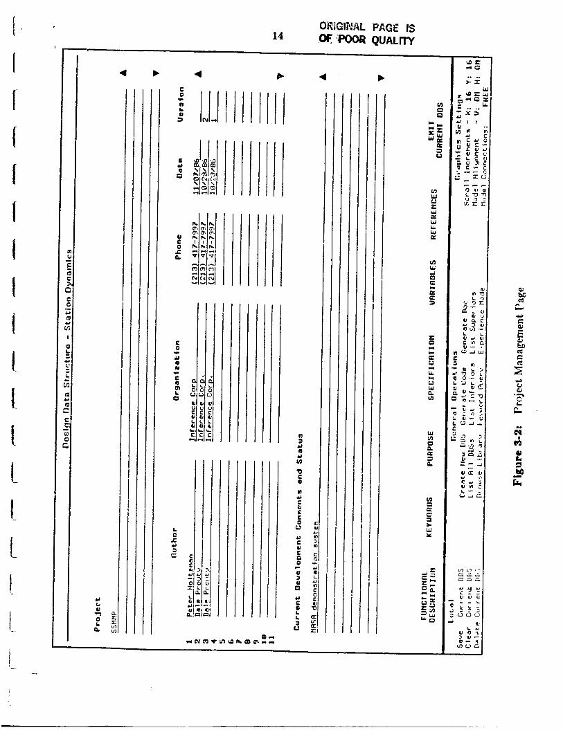
Specification Page B: Project Management Page
The Project Management page consists of three scrollable text fields used for project
management: Project, Vereion Hietoy, and Current Development Commen!s and
Statu8 (see Figure 3-2 below).
The Project field is a scrollable text field used to describe the project and role of this
DDS within the project.
The Version History is maintained by the system and displayed only. It is not entered
by the user and cannot be edited by the user. It gives the author, organization and
phone number of the logged in user who saved the version, as well as the date it "3s saved. The list is displayed by recency. The first line represent.s the DDS in tbe buffer,
and is not assigned a version number.
The Current Development Comments and Status field is a scrollable field for
comments on the current state of DDS design. It is used by the user to indicate what h a s
been done and needs to be done to complete work on a partially developed DDS.
4 b
c 0
n L
2
.c
a
a L) Q 0
u c 0 z IL
c 0
Y 8 N
E Q cn 0
.c
c
L C .e 4J
s a
4J
I /
I
n J 4J 8 L) u)
0 c 0
n
SJ S c 0 u Y c u c U 0
0 > u 0
c a L 7 0
2
c
Y
4
C V Y n
- ' $ L)
a L L) n C
c U
w II
a a,
- a z - 0
> I .. ..
L a- :-=: - - .. .. 2 x 3 '
L i U J w u .- C O G
, C I d W

BRiGiifdL PAGE i$ OF POOR QUALrW I 15
c C .- c
a L U
-2
I

16
Specification Page C: Purpose and Keywords Page
The Purpose and Keywords page contains the Purpose and Keywords text fields. These
fields are important for both documentation and the browsing facility (see Figure 3-3).
The Purpose field is a scrollable field used to describe the purpose of the DDS. This
field can be viewed from the library browser and is also used for generating
docurnentat ion.
The Keywords field is a scrollable field used to specify the keywords for this DDS to be
used in the cataloguing facility and for documentation purposes.
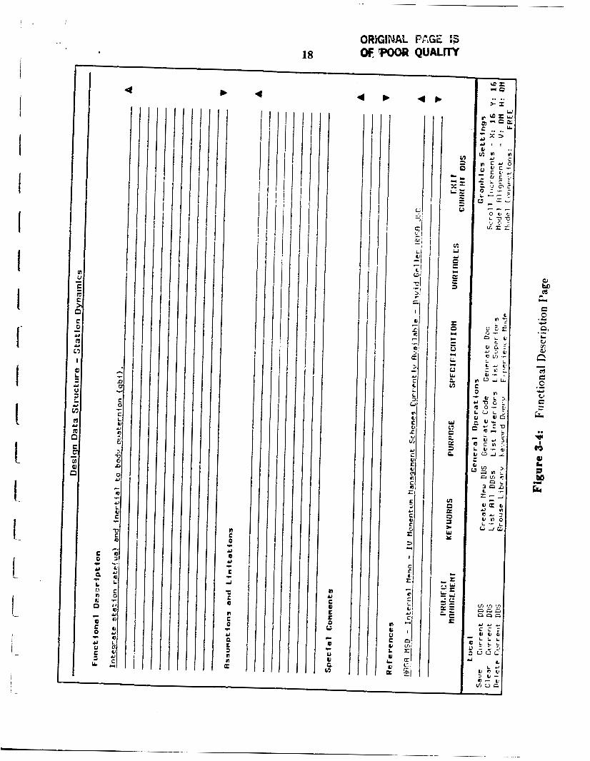
Specification Page D: Functional Description Page
The Functional Description page contains four scrollable text fields: Functional
Description, Assumptions and Limitations, Special Comments, and References (see
Figure 3-4).
The Functional Description field is documents the functional description of the DDS.
The Assumptions and Limitations field is for documents any assumptions or
limitations of the design specification.
The Special Comrnente field documents any special comments about the DDS that will
of interest for the user when the DDS is completed. A separate field is provided for
development comments (Current Development Comments and Status)
The References field documents any reference to other documents (books, papers,
memos) that may be relevant to the DDS.
Specificstion Page E: Variables Page - Graphically Specified DDS ONLY The Variables page for a graphically specified DDS consists of a Subroutine Name field
and three scrollable regions for describing input, output and local variables (see Figure
3-5). Local variables are used within the DDS but do not serve as either inputs or
out pu t.s.
17
The Svbrouline Name field specifies the name to be used by the automatic code
generator when generating the source code subroutine that corresponds to the DDS. The
DDS name may be longer and more descriptive.
The information about variables is used for code gencrat.ion, and automatic generation
of coordinate system transformations.
Scrolling in a scrollable region scrolls the variables lines so that an indefinite number of
variables may he used.
Each variable line has the following fields: Name, Description, Units, Variable Type,
Dimension, Coordinate System, and Data Type.
Several of these fields are choice fields. When the user selects these fields, a menu of
allowable choices is presented. The user selects the appropriate choice from the menu by
clicking the mouse on it. If the mouse leaves the choice menu no change is made.
The Name is a text field to specify the variable name.
The Description is a text field to provide a short description what the variable
represents.
The Units field is a text field to indicate t,he physical units associat,ed wit.h the variable
e.g. grams
The Variable Type ficld is a choice field that specifies the variable as one of the
following mathematical types: scalar, vect.or, matrix or quaternion.
The Dimension field specifies the dimensions of a vector or matrix. The dimension of a
scalar is 1. The dimension of a quaternion is 4. The dimension of a vector must he a
positive integer. The dimension of a matrix must be two positive integers sepnratxi by
spaces. The dimension of a 3 x 3 matrk is entered as '3 3..
i
I 1 I I I I I I I I 1 1 I 1 ! i
~
I
i
18
n E 0
Y 0 0
L -4
0 C O
C 0
Y
L 3
t
t
t
n
'c
a
n n a
n U E 0 L 0 u
Q
0 u G v )
r
c
c
- - -

19
O C SH j
0
n 2
0 c
a n u o n c
r X L C 0
v 1 3 c a a r Y
n Y
C 3
r
C 0 U R
L V
u
r
.F
n n
u c Q E
b
/ I / / / I /
I I I I I I I I I
v)
3 0 c
c
b
I1
l / / / / l I / /
I
Q
L 0 U l l l l l l l l l 5 LI
I L O 0 e 0 3 s w Y
I u u u c c c U V L .
- L L L O L L L u 3 3 3 O V V O
- 1 b L U
v a u > 0 . - a - u m v n

The Coordinate System field is a
The current acceptable systems are:
N/,4. The user selects this field with
with the Variable Type field.
20
choice field thatt specifies the
inertial, LVLH, body centered,
coordinate system.
principal auk, and I
the mouse and is presented with a choice menu, as
The Data Type field is a choice field that specifies the data type to be DObTELE or
INTEGER.
The variable lines are provided with default values and constaints.
When a variable is first defined by entering the name, the following defaults are
assumed: scalar, dimension 1, coordinate system N/A, and data type DOLBLE.
The default dimensions are: scalar 1, vector 3, matrix 3 3, quaternion 4.
Scalars are constrained to be of dimension 1 and quaternions cf dimension 4, no matter
what the user may enter.
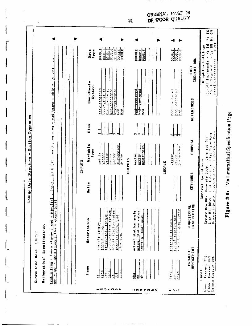
Specification Page F: Mathematical Specification and Variables Page
The hlat hematical Specification and Variables page for a mathematically specified DDS consists of a Subroutine A’ume field, a Mathematical Specification field and three
scrollable regions for describing input, output and local variables (see Figure 3-61.
Section 3.2.1.5 discusses the use of the mathematical specification field in more depth. .-
This screen is similar to the Variables page for a graphically specified DDS. It consists
of the Subroutine Name field, the Mathematical Specification field, and t bree scrollzhle
variable regions for input, output and local variables.
The Subroutine Name a i d variable regions are used as in the Vzriables page above.
The hlathernatical Specification field is a scrollable text field used for eritering
equations that Fpecify the DDS. These equations are written in S M P syntax and allow
vnriables to represent vectors aud matrixes. This high level mathematical language is
4 4 b
I l l
n Y
c 3
IC
u u) 0 R K
R a

- -
22
appropriate for indicating the specification of a DDS at a mathematical level withoct
having to write DO loops and programming constructs, although such constructs are
available in the SMP syntax.
The high level mnthematical specification together with the variable description are
used to generat e source code automatically.
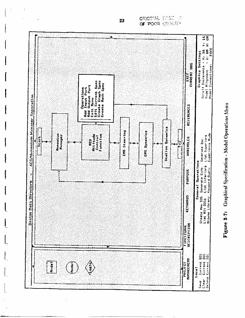
3.2.1.4 Graphical Design System
The graphical design syst,em allows a designer to build or edit control flow diagrams.
The diagrams are built by mousing on a 'v0c3bulary~ element from a palette of choices
and positioning them within an editable region, the design area (see Figure 3-7). The
Phase I palette icons represent generic design elements. No specialization was
attempted. When a design is located in the control flow and given a name, that naine is
tied to all library designs matching it by name. Several coices may be available for
linkage of the control block to a lower level, more descriptive DDS. These are all presented when the user begins the linkage operation.
The graphical design system supports most of the basicly desired operations for editing
- deletion, scrolling through a 'file', clearing the 'file' of buffer, and graphic-specific
ports on design blocks and connections amongst them. Deletions allow removal of single
elements from the design area (or buffer); scrolling allows flow diagrams larger than
design area size to be viewed, built, and stored; and clearing removes all elements from
the buffer. Ports are positioned after a menu selection that arises via mouse click on a
specific design block. Connections are then added between blocks by mousing the
respective port mouse sensitive areas. Each connector is given its own mouse sensitive
are for use in obtaining a menu of observation or results options.
Certain operations (displayed a t the bottom right of the screen) relate to default
settings for the graphical design system. These may be adjusted as the user desires for
such things as scrolling increments and alignment cf control blocks.
The general intent is to mzke the graphical editing area similar in nature to an
EhWCS buffer, but with graphic-specifc operations.
j
c d c: c c ed
.C

24
I 1
t I L
The implementation of the graphical design system is accomplished by dividing the
middle section of the screen into two scrolling areas, one, a palette, for the generic or
specific graphical design vocabulary, and the other, a design are for laying out or editing
control flow diagrams. Scrolling is available via mouse sensitive g ~ c r ~ l l markers.. The design layout is accomplished via mousing a palette icon, positioning the replica in the
design area, and, if the icon is generic, filling in the design name. Additional graphical
operations are reachable via a mouse click on the design .iconm, or via the bottom
section operations (such as delete, etc.). Ports and degin flow connections are
accomplished by selecting the input or output po:t operation from the design icon menu,
locating the port on the design icon, then connecting ports by clicking on the port mouse
sensitive areas, input to output or vice versa.
3.2.1.5 Mathematical Design Level
The mathematical design level or leaf allows a designer to build or edit engineering
mathematical specifications. The mathematics is written in SMP using engineering
terminology and syntax, including dealing with vector manipulation such as dot and
cross products. The SMP code written is later used as input to the Fortran code
generation process. The specifications written in Phase I were for the attitude control
system.
3.2.1.8 Implementation
This section describes the implementation of the DDS description screens, with the
except ion of the graphical specification.
Each DDS is implemented as an ART schema together with some associated facts. The
schema name is internally generated so that various DDSs c3n have the same textual
name. This is possible because the name is actually a slot of the DDS schema.
Inferior DDSs within a graphical DDS are represented by a model fact which describes
inferior DDS in relation to its superior. The actual icon on the screen is represented by a
model-icon-description fact. The model fact ties the unique icon name to an inferior DDS
schema. Thus the actual inferior schema may be changed within the model fact without
affecting the model-icon-descriptor fact.

25
A pushdown list of DDSs are maintained in
variable length sequence and the current schema
the design-process-buffer-list fact as a
is at the top of this list.
The current DDS is also maintained in the wksta-current-dds-type fact.
The presentation and editing of the all screens, except for the graphical specification
screea, is performed by a set of general rules, facts and schema for handling a multiple
scree3 form in an ART graphics window. The form associated with the DDS nlso uses
some specific rules and uses variants of the general rules. Each form has a specific name
that is not seen by the user. The form used for the DDS screens is called .model-
dscriptor..
The form rules are driven by certain facts and schema.
The form-window-schema fact identifies the form name, the windows involved, the
schema that the form represents (in this case the particular DDS schema), the particular
scrdl schema, and slots corrosponding to scrollable fields.
The scroll schema uses its slots to maintain the scroll position of all scrollable textual
fie!ds and regions (authors and variables).
Most fields are represented as form-value-field-run facts. These facts describe each
form. They tie together information necessary to identify the field (the form name,
window, and field tag), the corresponding slot name in the underlying schema, the
position of the field in the window, and the field type. The field type specifies whether
the user interacts with the form via the keyboard or a choice menu.
There is also a facility for handling related related fields such as the component fields
of a vsrisb!e or version history line.
These fields are represented in the DDS as subsequence elements in a DDS slot. The
slot is a multiplevalue slot to allow for several lines or blocks of related fields - and e x h
slot icstance has a number associated with it as part of its value.

I
26
Each type of block has an associated name. Each window region where the blocks may
occur is given a region name.
The scroll schema contains a form-complex-field-region slot that describes the window
region containing repeating blocks to be scrolled simultaneously. It defines the window
coordinates of the region, how many blocks are displayed, and the first block actually
displayed. A form-complex-field-subfield slot describes the block - i.e. the relation of the
subfields to the subsequence values and acts as a form-value-field-run fact.
Form rules exist to display form pages (screens), to update individual fields, and to
perform scrolling.
The display rules draw the form on a background form window, and then bitblt it to
the foreground window, create the mouseable areas and expose the foreground window.
This allows an clean visual transition from one form page to another. The rules access
the current values of the DDS via the ART get-schema-value function. They also use this
function to get values from the scroll schema to determine what parts of the DDS schema values and slots should be displayed on the limited window area.
Whenever the form-window-schema fact specifies a DDS which is different from the
current DDS as specified by the wksta-currentdds-type fact, the form-window-schema
fact is updated to tie the form to the current DDS and the scroll schema is reset.
The utterances asserted from mouse clicks on the mouse sensitive area of the form
indicate the form name, the window, the field tag and some indication of the field type.
One rule responds to utterances with associated form-value-field-run facts that specify
input from the keyboard. They pass current slot value to a lisp function which accepts
input from the keyboard and provides m a y of the normal editor commands. This function returns the new value. The slot value is then changed via retract-schema-value
and assert.
A similar rules handles utterances with an associated form-value-field-run fact thrrt

i
i 27
f i
I I I !
indicates a choice menu. The choice menu is constructed and exposed and returns the
appropriate choice. The form-value-field-run specifies the allowable choices (or
enumerated vnlucs as they are refered to in the ART source code). In addition to
modifying the schema value, this rule prints the new value on the form window.
T h e associated fields described by form-complex-field-subfield slots are hnndled
differently. In this case the utterance specifies the field tag that describes the field on the
window. Two rules pick up this utterance and calculates the corresponding slot in the
DDS schema, based upon the scroll schema’s information as to which slot is the first slot
displayed in the window region and either calls the lisp function or constructs a choice
function as above. There is one rule for keyboard entry and one for choice menus. These
rules differ from the above rules in that they are of high salience, and assert that the
corresponding window block should be redrawn by using a form-region-display fact.
In the case of variable lines, which have associated rules to implement defaults and
constraints, this allows these medium salience rules to fire and modify other subsequence
elements in the modified slot value.
Finally a normal salience display rule fires to display the block. There are two such
rules. One for variable blocks and one for version history blocks. These rules actually call
special lisp functions to draw on the window. This is so the page display rules can call
the same lisp functions directly, without going through the overhead of asserting
multiple form-region-display facts and causing multiple rule firings.
Scrolling is handled by a set of rules which modifies the scroll schema, bitblts the
portion of the form window that remains visible to an offset position in the same window
and displays the new part of the screen produced by scrolling.
There are general rules for doing this. One set handles normal fields, the other complex
fields that use form-region-display facts to redraw the new block.

i 6 I I I I i I I I I 1 c L I I I I I- \
28
3.2.2 DDS Operations
As any DDS is edited there are a set of possible operations that are supported outside
the actual editing environment. These are all rather straight forward. The conimands
are reached via text and mousable regions a t the lower portion of the screen (see several
of the previous Figures, e.g. Figure 3-7, p.23). Each is recorded below with a brief
descriptor. They are implemented via a LISP function that sets up the text and mouse
areas, and utterances arrive into ART where rules respond appropriately.
Local Operations:
0 Save Current DDS - catalog the design in the card catalog system and enter it in the library
0 Clear Current DDS - remove all designs and connections from the current DDS, clear the design area
0 Delete Current DDS - delete this design from the buffer
Global Operations:
0 Create New DDS - create new design buffer
0 Generate Code - generate Fortran code for DDS
0 Generate Doc - not implemented in Phase I
0 List All DDSs - bring up the buffer list
0 List Inferiors - not implemented ( l i t of inferior DDSs)
0 List Superiors - not implemented (list of possible superior DUSs)
0 Browse Library - enter the browsing facility
0 Print Screen - not implemented (hardcopy facility - site specific)
0 Experience Mode - not implemented (Usage of Help facility)
Graphics Settings:
0 Scroll Increments - x and y default scroll increments

29
I I I i
I
1 I
0 Model Alignment - vertical and horizontal alignment of design icons
0 Model Connections - not fully implemented (free drawn connectors between DDSs or rectangular line connectors)
3.2.3 DDS Librarian
Design Data Structures within the Automated Software Development Workstation are
persistent objects which are managed by the DDS librarian. The librarian is a service
that organizes information about the DDSs in a conceptual manner that is approprizte
for the user of the workstation, and uses the underlying file system to actually store and
retrieve information. This relieves the user of the burden of managing the file system
manually and keeping track of which files are related to others, and allows the user to
browse the library according to meaningful categories such as DDS names or keywords,
rather than file names. This is especially useful because a single conceptual DPS may
have several files associated with it.
The library is maintained as schemata within the ART database, which point to all
files associated with a DDS. It is also maintained in the file system as 3 system file.
The librarian performs the basic operations of cataloguing and browsing. It is also used
in the selection of inferior DDSs in a design hierarchy.
3.2.3.1 Cataloguing
The catalogue operation, is invoked when the users mouse selects the Save DDS field
whiled editing a DDS. It saves the information associated with a DDS in file(s) and
catalogues the DDS in the library. Other modules, such as source and data files may
eventually be catalogued with the DDS entry. The librarian maintains its own version
system to distinguish various versions of a design or separate designs with an identical
name.

30
i I I I I I I t I 1 1 I- t 1 I - I I
3.2.3.2 Browsing
The browse operation of the Librarian is the Electronic Card Catalogue System which
is organized in a fashion similar to manual card catalogue systems in traditional public
libraries. DDSs may be browsed by Design (title), Desiper (euthor) or keyword (subject),
as in a traditional library. Additionally designs may be browsed by Froject. Unlike traditional systems, several topics may be browsed at once such as designs for a Space
Station hiamenturn Manager, or designs having to do with 'momentumm or designs
authored by John Smith. This allows the user to specify sufficient information in a single
query.
In keeping with the graphical presentation style used throughout the workstation, the
librarian represents the DDSs graphically using the the terminal screen as a scrollable
viewport on the graph of DDSs and the user can interact with the librarian via mouse
selection. This is implemented by the use of the 'ART graphical schema browser'.
Individual designs are represented in the browser by appending a parenthetic
expression of the form: (design-number . version-number) The design number indicates
differentiates between various DDSs which have identical names. The version number
identifies different versions of the same DDS.
Figure 3-8 shows the screen which represents a user query to browse the library.
Figure 3-9 shows the resulting graphical presentation of the associated DDSs.
Figure 3-10 shows viewing the purpose of a library design from the browser for
purposes of possible editing or inclusion, i.e. reuse.
\VhiIe browsing the library, the user may mouse select a particular DDS to either yiew
its purpose or to load it into a workstation editing buffer. Viewing the purpose produces
a scrollable wixdow, showing the purpose associated with the DDS.
It is important to note th3t the DDS is not actuslly part of the running database, ocly
its library schema is present.

I I '
I
!
31
4 c c,
L) 0 u u n a 3 0 C
0 C Q
%
Q L
c
e c
a r L)
e b . c c - 0 n - a c , 0 0 L Q P m L Y 0 0 L I
L n o a 0 e L ~a o a m Q 0 Y Q u 0) C
s 0
0 L
a z Y
c
- c c
c
c c c L
n 0 E 0
a
c
r O1
n 0 C 0
n 0
e
a
c c a
M N Q)
L L L
C C C
n n n 0 0 0
a a m m o m
u a u e - -
M N Y Y u u m a 9 3
P O e e
0 Y 0 Q 7 0 L 0
L OI
n C a n c
0 0 c P c
1
a C
L
c U C
C 0 F
r(
C m n e
0 0
N O c c m m c c n n a u P O
c a m a 0
c w
0 0
.. n C 0
Y 0
c
a
t% i c 0 2 ..
a3 (3

I
I
I I I I I I 1 I I i I L 1
! I L
I

I
I I t I i. L I
33
U 3 0 U 0
u c Y
L 0 c E 0
. . . . . . . . . . . .
w d U LL 0
0 d
a
3 w s m
c U x w
f I I
I t t
L !
34
The load operation, actually loads the associated file(s) into the database, 2nd places
the DDS into an editing buffer which is then selected to be edited.
For Phase II the browser should be enhanced to present the design hierarchy. Conlext
sensitive synonym tables should also be introduced to allow reference to design with
similar purposes but different names.
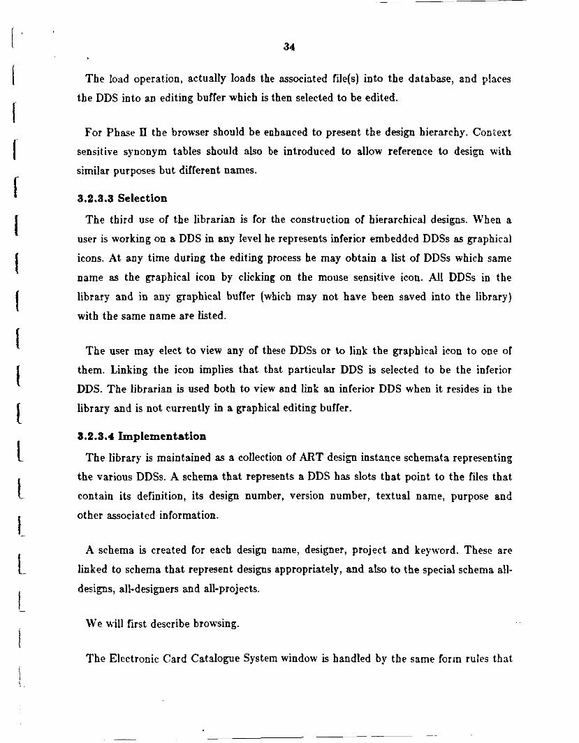
3.2.3.3 Selection
The third use of the librarian is for the construction of hierarchical designs. When a
user is working on a DDS in any level he represents inferior embedded DDSs as graphical
icons. At any time during the editing process he may obtain a list of DDSs which same
name as the graphical icon by clicking on the mouse sensitive icon. All DDSs in the
library and in any graphical bu€€er (which may not have been saved into the library)
with the same name are listed.
The user may elect to view any of these DDSs or to link the graphical icon to one of
them. Linking the icon implies that that particular DDS is selected t.o be the inferior
DDS. The librarian is used both to view and link an inferior DDS when it resides in the
library and is not currently in a graphical editing buffer.
3.2.3.4 Implementation
The library is maintained as a collection of ART design instance schemata representing
the various DDSs. A schema that represents a DDS has slots that point to the files that
contain its definition, its design number, version number, textual name, purpose and
other associated information.
A schema is created for each design name, designer, project and keyword. These are
linked to schema that represent designs appropriately, and also to the special schema all-
designs, all-designers and all-projects.
We will first describe browsing.
The Electronic Card Catalogue System window is handled by the same forin rules that

35
I
I
I
I
i
implement most of the DDS screen windows. These
in a fixed known schema.
collect the users specification as slots
When the user activates a browse two groups of rules are invoked.
Thc first groups uses the rued schema to collect a11 initial schemata and relations to be
browsed. It then traces out the schema subnetwork to be browsed and mshadouysm the
relations by temporary relations which are logically dependent on a wksta-library-
shadow fact. This prevents many unwanted schemata tlo be browsed. TLis is because the
schema browser browses by both primary and inverse relations.
The second group actually calls the schema browse function. This function must be
called with a unique initial schema. If several initial schemata are needed they are
temporarily joined to a unique initial schema by asserting relations which depend
logically on the temporary-join-in-progress fact.
The ART interface browse function is called to display the library subnet graphically.
In addition, the rules will first retract the wksta-library-shadow and t,emporary-join-in-
prog-ress facts if present, to clean up any temporary relations created by previous
browses.
There are rules to respond to mouse clicks in the browser window in the appropriate
fashion - Le. either loading the file or displaying the purpose. A file is not loaded if the
DDS is already in 3 buffer list - to avoid merging two versions. The rule to actually load
the file, uses the dds-name slot in the library design instance schema and a not pattern
for finding this dds schema on a buffer list. -
Catalopeing schema ccnsists of creating the design schema and also m y missing
keyword, project, designer or design name schemata and writing out dds schema and
associated facts as well as lisp file which is also compiled.
The catarogueing rule fist asserts the most of the necessary schema slots, and also

36
I I
I
f
!
!
appends their definition to the library file. It uses a wksta-dds-descriptor to pass the
design instance schema and library file stream to the actual save rules. These save the
ART and lisp files, assert the pointers to these files, aDd write out the slots to library
schema.
The librarian supports the linking of a DDS inferior icon to a DDS by providing a rule
that will load the most recent version of a dds schema file when a wksta-load-most-
recent-dds fact is asserted. It locates the most recent version and essentially asserts a
fake load utterance from the schema browser.
The rules associated with the schema browser also maintain the appropriate icon in the
bottom operations window at all times.
3.2.4 Automated Programming
A facility for automated generation of Fortran code was produced. Fortran
subroutines can be written that represent each DDS level from high level graphical to
the leaf mathematical specifications. Thus the graphical specifications consist of a
subroutine which itself contains a set of variable declarations and other subroutine calls.
The mathematical specifications lead, via ShP, to Fortran subroutines that contab
engineering mathematics and appr0priat.e calls to accomplish required lower level
mathematical functionality.
3.2.4.1 Graphical Program Generation
ART rules write Fortran subroutine calls and do variable declarations for graphical
program generation. The subroutine calls get written in sequence simply by having rules
that wait until all inputs are knowD, then propogate this to the outputs, on to the next
inputs, etc. The process is begun at the 'START' DDS found at each graphical level.
All the inputs to this DDS reside here. The outputs of START are propogated forward
to become known inputs for the next designs, code is written, and END is reached. This
closes the subroutine with the normal 'RETURN/END' lines.
37
8.2.4.2 Mathematical Program Generation
ShlP code is written on the leaf element mathematical specification page. This code is
translated into Fortran with variable declarations as specified on that same page for
input, output, and local varaiables. A Fortran subroutine results with most of the
several pages of specification added as in-line documentation.
To accomplish program generation, S A P is put in a loop running on the VAX (via a
VMS command routine) so that ShP is awaiting arrival of a specific file over the
network. When this file arrives, the S I P processing begins. The result of this
processing is the Fortran code generation. T o accomodate the appropriate variable
declarations and code generation several S h P utility functions are utilized on the VAS. These functions deal with the vector mathematics required in most engineering
disciplines, the variable specifications from the specification page, and standardization of
mathematical syntax from that which typically exists in the field. The processing is
primarily done by the SMP function .Wkstaprog. which uses Ship functionality
appropriately to accomplish the code generation via .Pro&., a standard S h P function
for code generation from analytic expressions. Sh4P does not fully support all necessary
variable declarations as desired, so a brief C program does a final editing of S I P
generated code before passing the code Lack to the Symbolics for final file (module)
construction and storage.
3.2.5 Results Presentation
A presentation of results facility is necessary for both batch and interactive simulation.
This facility hay not been produced in Phase I since it relies heavily on extant plotting
facilities and is of limited interest to the demonstration of AI’S usefulness. A menu can be chosen on all graphical links that introduce a form and/or plot specification package,
see Figure 3-11. These packages should allow full specification of the plot DDS similar
to those of the design DDSs. Thus, for example, solar array occlusion of the sun by the
earth could be plotted versus orbit location and/or time, and could be reused just as a
design could. The results facility is intended to be an integrated DDS !ype capability.

cDL -0
>I .. ..

39
3.2.6 Execution
Phase I did not complete an executable simulation due to time limitations. Code was
generated for various DDSs that could be incorporated into a program, but no specific
facilities were made available for establishing linking and compilation of these DDS software modules, nor was an effort made to provide the more sophisticated interactive
simulat,ion capability.
3.2.7 Debugging Designs
Debugging designs is a topic for executable simulations. Since no execution facility was
completed this is left to Phase II.
3.2.8 Automated Documentation
As called out in the SOW, no Phase I effort was to be spent a t this effort and none
W a s .
3.3 Tutorials
There are two cursory tutorials on current workstation functionality - installation 2nd
usage. The installation briefly describes the necessities in setting up the workstation; the
usage tutorial leads a user through an example of starting an attitude control subsystem
design and cataloguing.
3.3.1 Installation
An automated installation procedure has been provided with the workstation.
The workstatioa software is combined to run under ART 2.0 on a SYMBOLJCS computer which is networked to a Digital Equipment Corporation VAX computer which
runs S A P under the VhlS operating system.
The workstation requires the use of a Symbolics - Phi!ip terminal.
To install a workstation the system manager must c;eate an ShlP account on the \'AS, a workstation login on the SYMBOLICS, and create a workstation band. E x h
40
I I
I I I I I I I I I t I I- I- I - 1 - I
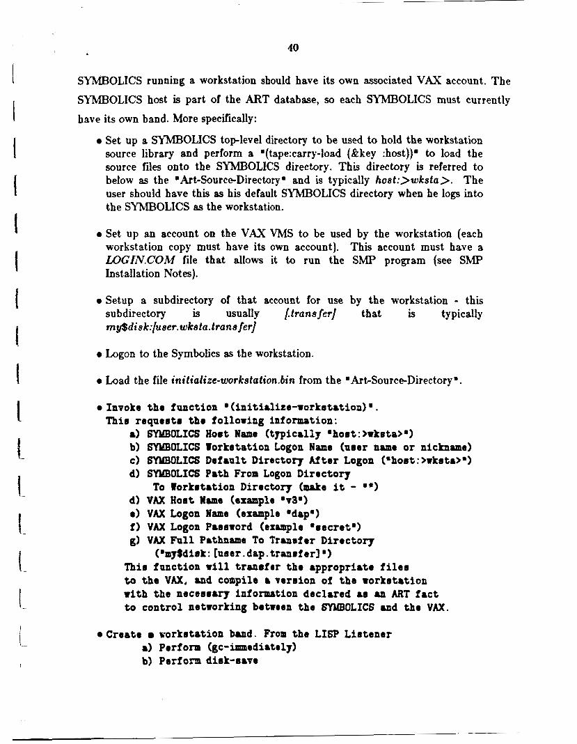
SYMBOLICS running a workstation should have its own associated VAX account. The
SYMBOLICS host is part of the ART database, so each SYMBOLICS must currently
have its own band. More specifically:
0 Set up a SYMBOLICS top-level directory to be used to hold the workstation source library and perform a .(tape:carry-load (&key :host))' to load the source files onto the SYMBOLICS directory. This directory is referred to below as the mArt-Source-Directorym and is typically hoat:>wksta). The user should have this as his default SYMBOLICS directory when he logs into the SYMl3OLICS as the workstation.
0 Set up an account on the VAX VMS to be used by the workstation (each workstation copy must have its own account). This account must have a U)GIN.COM file that allows it to run the S M P program (see S M P Inst allat ion Notes).
0 Setup a subdirectory of that account for use by the workstation - this subdirectory is usually /tranefer] that is typically m y$d i s k:[u e er. wke tu. t ra n e fer]
0 Logon to the Symbolics as the workstation.
0 Load the f i e initialize-workstation.6in from the mArtSource-Directorym.
0 Invoke the function (initialize-rorketation) '. Thio requertr the folloring information:
1
SYMBOLICS Hort Name- (typically 'hoot: >wketa>') SYMBOLICS Torketation Logon Name (mer name or nickname) SYMBOLICS Default Directory After Logon (mho8t:>rksta>o) SYXBOLICS Path From Logon Directory
W A X Hor t Weme (example ' ~ 3 ' ) VAX Logon Name (example 'dap') VAX Logon Parsrord (example .recretm) VAX Full Pathname To Tranrfer Diroctol.~
To Torkrtation Directory (make it -
(mmJSdiek: [ursr.dap. tranefer]') Thio function rill tranrfer the appropriate filer to the VAX, and compile 8 version of the Torkrtation with the necer~ary information declared a8 an ART fact t o control networking between the SYABOLICS and tho VAX.
oCreate workrtation band. From the LISP Lirtener a) Perf om (gc-innasdi8tely) b) Perform dirk-rave
41
I I I I I f I f I I t I ! L ! !. i
0 Create a boot file for loading the workstation band.
The workstation stores its program libraries in the workstztion .logon' directory. If you wish to use the initial library provided with the workstation you should copy the
'library' subdirectory of the 'Workstation-Directory. up to the workstation logon
directory. In addition you must edit the file 'dds-browser-1ibrary.art ' in the worksta.tion
logon directory. This file contains the full pathname to the actual files. Please use
ZhlACS to replace the string 'CHANGEME' with the actual workstation directory
(e.g. 'host:>wksta> ').
3.3.2 Usage
Usage consists of logging in, obtaining the desired designs from the library, editing or
establishing new designs, and generating Fortran code from the graphical or
mathematical specifications.
3.3.2.1 Logging In
With the workstation band loaded, you should go to ART via select-A, as usual. The
'RUN' menu option should be selected from the ART command window. Some
initialization of windows, etc. will occur and a login form will appear. If you are known
to the system when you enter your name on the top line, your stored vitiae will be
presented. If any adjustment is to be made, each region is mouse sensitive, and may be
selected for modification. If you are new, the information should all be filled in, as this
data is used to automatically finish design specifications regarding author, etc. When
this procedure is completed, the card catalog system is loaded, and the library is
available for browsing, loading designs, or starting new ones.
3.3.2.2 Library Browsing
After login, you are presented with an option to enter the library browsing facility, via
a mouse sensitive region at the bottom of the screen, or to choose a current project. The project organization is intended to allow a user quick access to a list of current project
designs. This facility is not fully implemented and just leads you currently to starting
new designs. More interesting is the facility for browsing the library. Select this at the
bottom of the screeii.
r
I 42
1 t
I 1
A form appears for th? user to fill out. The options parallel those of a normal card
catalog system such zs autbor, title, subject (project i3 added). The options are designer,
design, project,, and keyword (subject). You may fill in any of the slots and a complete
hierarchy of all included information will be presented. A more sophisticated
presentation format awaits Phase Il, as ART internab will have to be adapted and more
pruning of the browse information would be needed. However, the Phase I browser
presents the library through use of the graphical ART schema browser and its mouse
sensitive icons. Mousing left on one of the leaf icons loads that design. Mousing middle
allows you to view the purpose of the catalogued design. While viewing the purpose, you
will find a selectable option to load the design or to return to the browser.
Toggle the 'NO' for ALL DESIGNS to 'YES' and mowc DO IT.
Currently each catalcgued design must be individually selected from the browser. No facility for loading multiple designs simultaneously exists. As each design is selected it is
loaded and it is entered in the buffer list similar to an EhlACS file buffer list. Each
design consists of multiple pages of design specification. The page first displayed is
always the graphical flow diagramn or the mathematical specification page, as this is
likely to be of most interest. Note that you will leave the browsing system when you
load a design. You will be in the design editor facility. You may return to the browser
by selecting one of the options at the bottom of the screen when the design has been
loaded, if you wish to load additional designs.
Load the design from the library that is titled 'ACS/Momentum hlanager Separation.
with the largest version number.
3.3.2.3 Editing Facility
The flow diagram should appear for the attitude control subsystem. The diagram does
not need to be edited, but should give YOU an idea of the type of diagram that you might
construct. You should note several things. Within the design region there are scroll
markers to allow for diagams that are larger than screen size. The palette on the left is
used for creation of new designs. The palette currently used is generic, but. specific
43
I I I f
t t
t
palettes that are project, or at least workstation incarnation specific will later be added
with a facility for the user to add new icons. The graphical icons represent effectively
the language available to you. Specific icons would imply specific vocabulary otpions
that are frequently used, but currently the generic ones are presented. Later we will
build a new one.
At the bottom of the editing and palette regions you will see the specification
categories required to be filled out for full design specification. Each will lead you to a
page of the specification that must be fdled in. These have already been filled out. Just
browse the various pages by mousing any of the various options. Observe all thc.
information that is required for a design to be fully specified for the library.
At the bottom of the screen, you will see many options. Most have been implemented,
some have not. On the far left are the options available regarding the current design.
You may save it to the library - this means storing the entire multi-page specification.
Currently, you may save a design without all specification pages being fdled out, this is
likely to change in later Phases. You may clear it - this means start the diagram over
and wipe out the current graphical diagram. You may also delete it - this meacs starting
over entirely on the specification.
In the middle of the bottom of the screen you will fmd many options. They are described elsewhere, but the ones worthy of note for the tutorial are 'Browse Library'
whcih leads you back to the browsing facility, the .Generate Code. option which should
only be used as described below, and the 'List All Buffers' option which brings up your
current buffer list just as in E M C S . The buffer list allows you to select other loaded
designs for editing just as in EMACS.
At the far right of the bottom of the screen yo^ will find options that sre used for the
graphical layout. Default values are shown for scrolling increments, block aligrment,
and line type. The first two are implemented. The scrolling increments determine the
jumps made when scrolling in pixels. The block alignment allows you to keep blocks
aligned vertically or horizontally in a diagram. i

i I
I I I I I I t I t I 1 t 1 ! I- ! ! -
44
You may try various of the botom screen options as you desire. Beware of the
consequences if clearing or deleting. Hoever, library designs may be reloaded.
Generating code for the diagram is described below.
3.3.2.4 Graphical Spec
Let's begin anew, and just draw a simple flow digram. Select the 'Create New DDS. option from the bottom menus. You are now to enter a name for the block by typing.
Call it 'ACS/Momentum Manager Integration'. Then the editing region and palette
will appear. You may exit this design and return to the previous via the 'Exit Current
DDS' option at the bottom of the editor and palette, or via the 'List All DDSs' option
from the bottom menu. Note that. all pages of the specification may be reached by the
region containing the .Exit Current DDS' option.
Let's draw a diagram. Mouse left on the rectangle of the palette. We first must build
a 'START' block. This block is intended to contain initialization statements for the
design (i.e. later for Fortran DATA statements). Position the f i t mouse click at the
location below but near the top center of the editing region where you wish the upper
left corner of the block to appear. A rubber rectangle will then appear and you must
position the lower right. Next you must type 'START' in the block. Next go back to
the palette and mouse the rectangle again. Position it an inch or more below the
START block. It will align automatically. Type the name 'Momentum Manager' in
the box with a carriage return between Momentum and Manager. Note that the text is
centered automatically. Note that is you make an error you may delete a block by
clicking right. You will then have to mouse the palette and locate and name the new
block.
Now, you may link the START block to this one. First, ports must be constructed on
each block, then links cau be made. Click middle on the START block, A men9 will
appear that contains INPUT PORT, 0VIT"I'T PORT, and other items. Select
OUTPUT PORT. The menu will disappear and the mause can now be seen to locate
the position of the pozt line. Simply observe the line O n the block as you move the
mouse. Four center lines have
the center lines of any side.
45
been provided for you to align ports that are desired on
Click at some location for the port construction. The
orinigal menu will appear for additonal port construction. Choose the Exit Menu option.
A small mouse sensitive area for the port may be found at the farthest edge of the arrow
from the block. You may delete the port by clicking right on this area if you have
positioned it in error. Also the mouse area is later used to connect with the other block.
We will see this in a minute. Next, click middle on the Momentum Manager block and
choose the INPUT PORT option. After these two ports are
created, you may link blocks. Simply, click left on the small port area of one of the
blocks. Then move the mouse to the other port area and click left. You will see a
mouse sensitive area at the mid-point of the connecting line. This is to be used in later
Phases for results presentation and data flow observation during simulations. For now it
allows deletion of the connection if an error has been made by clicking right on it to
delete the connection.
Position it as before.
Additionally, the conect,ion link may be a segmented line by simply clicking at any
chosen point to make a bend in the line. As many segments as desired may be added,
then proceed to a port mouse area to finish the line. Note that clicking right during this
procedure deletes the last line segment so that you may reposition it.
Now you see how to build flow diagrams. You may continue to build further block and
link them as appropriate for an attitude control system. Next you may want to fill in
other pages of the specification. Please browse and enter some appropriate information
for this design assuming it regards the building of a space station attitude control
subsystem that integrates the momentum manager and sttitude control functions. Note
that it is difficult to fill in the variables for input, local, and output to this design.
Currently the user must fill these in. Later Phases would aid you by percolating the
information from lower level specs.
Now return to the graphical flow diagram. Click middle on the Momentum Manager
block. You will see in the list of options 'DDS 1'. If other library deisgn were of this
same name it would list them as options also. If you desired to connect this block to the

46
stored one you would select DDS 1. Otherwise, you would choose to create a IICH'
graphical or mathematical specification. Creating another graphical spec is idestical in
nature to this one, so let's create a leaf mathematical specification. Click left on the
create math spec option.
3.3.2.6 Mathematical Spec
The specification page will appear for entering mathematical design information. This
leaf level routine should be named for Fortran purposes. The next entry is a
mathematical specification of the design. S M P is used later to translate this
mathematics into Fortran code. Vector mathematics may be used with dot products,
etc.
Before attempting to create this mathematical specification, let's review one that
already exists. Simply click on 'Browse Library' at the bottom of the screen. Kest, click on the DESIGN 1 mcuse a rea , and enter 'ACS Attitude Control Function'. Then hit the END key or click outside the DESIGN 1 region to enter the information. Then
click on DO IT. When the design hierarchy appears, select the latest version of the leaf
design, and load it by clicking left. You will see the mathematical specification with all
pages availahle as usual. View the mathematical design for an example of the
engineering mathematics supported.
Then click on the EXJT CURRENT DDS options. This will return us to the last spec we
First, let's name this routine 'ATTCF' by
option in the row of syt.:Xcation page
were working on.
mousing the subroutine name area and
entering the data. To exit, simply press end after typing or click outside that mouse
area.
Now let's enter some simple mathematics for the specification (inappropriate to ti.is
design, but possibly instructive). Enter this continuoulsy on the first line of the
Mathematical specification. Note that most of t,he simple EhIACS editing co rnmuds
work in all text entry areas.
thc = ( t h t r s ,
47
I t t I ! I L !
All variables must be also be declared and typed as you saw in the other mathematical
design. I! you wish to review it, simply go to the bottom center menu and select .List A 4
DDSs.. Select the Attitude Control Function design and review the variables page, t!,eu
return by mousing 'EXIT CURRENT DDS..
For our variables we will enter inputs, outputs, and 10ca.k Under Input 1, mouse the
variable name area and enter hcmg then click outside. Next enter the desciiptivc d.ita
by mousing in that area and entering CMG momentum. Again click cutside. You will
note that two separate mouse clicks are required - one to finish the entry and one to
begin another. Continue filling in the appropriate data for hcmg. Note that menus of
options appear for coordinate system, variable data type, etc. The control moment g-yro
momentum is a vector with the default dimensions (3). After hcmg is completed with an
INERTIAL coordinate system and DOCBLE precision., enter imom as Input 2, and
continue as before. The variable h o r n contains the principal moments of inertia fcr the
space station (Le. it is a vector of dimension 3 with the coodinate system 'N/Am and is
the default DOUBLE precision. Next enter Input 3 tu@, a double precision scalar that is
the orbit frequency; then t as the orbit time, a scalar; then thtea a scalar angle; etc. The
enter fhc as Output 1, which contains the commanded station angles (a vector of
dimension 3). ShrP inny
generate local variables to optimize computation, such as for wO4.
There are no local variables specified by the user here.
Next fill in some information that might he appriopriate on the various specificatim
pages and finally click on 'Save Current DDS' at the bottom left. This will store your
design away, and place it in the library card catalog system.
Finally, we are ready to 'Generate Code' for this design.
Special notes: the START blocks are always to be nlathemstical specifications and the
data entered is to be initialization data for Fortran DATA statements. See the exanzple

48 h
provided by browsing the library and reviewing Fortran code generated at the flow
diagram level. End blocks must finish each diagram, and require no lower level
specification.
3.3.2.6 Code Generation
The mathematical code generation is accomplished by S M P on the VAX. When
selecting generate code a file is created with the same name as the unique design name
(like mDD!3-06/23/86 12:00:00') with a type extension of '.FTN'. ART puts all the
specified information in the Fortran file as header informstion (just as NASA currently
does for in-line documentation). ShlP generates the declzratims and body of the code.
To view the results, you must go to EMACS and look at the file. It contains the
documented Fortran source code.
If vector mathematics has been used, a set of Fortran low-level utilities is called to
perform the vector algebra. These have the following s y n t x each starts with the letter
specifying the variable result type - S for scalar, V for vector, M for matrix, and Q for
quaternion. The second letter tells of the first, argument with the same notation; the next ..
letters specify the function, nd the last specifies the second argument type. For
examples, QQADDQ implies adding two quaternions which returns a quaternion,
WDOThl implies a dot 2roduct of a vector with a matrix that returns a vector. ?'he
utilities perform dot products, cross products, and multiply, add, subtract, etc. T!I se
utilities are trivial Fortran routines and would have to be loaded during linking froii: a
utility library. Later, with more sophistication, in-line code could be placed for t!. se
functions based on user selection to optimize the Fortran execution.
Go ahead and try it. The result should be roughly identical to that shown in I : e
'DDS-10/28/86 11:07:08.FTNm.
We will not generate code for a graphical specification in this tutorial, but it procccds
identically. MtT calculates the flow and builds the Fortran source fde in the graphical
case. For graphical code generation, however, note 1) you should save the current design
prior to code generation so that the code is consistent with the design, and 2) all designs

e 49
referenced by the flow graph (at one level lower) must have been saved previously so
that the subroutine calls can be referenced appropriately. This should lead to successful
code generation.
Go to EhL4CS and view the fie .DDS-10/28/86 10:55:W.FTNm for the . ACS/hlomen t um Manager Separation ..
3.3.2.7 Domain Expertise Rule Use
This is to be the main area for focus in Phase XI. Phase I only attempted to perform
coordinate system transformations between graphical blocks as necessary to connect two
slightly disparate library modules. This capability is demonstrated for the top levei
.ACS/Momentum Manager Separation .. See library file .DDS10/2S/86
10:55:09.FTNm.
3.3.2.8 Simulation Capability
No real simulation capability was attempted during Phase I. Thus feedback in flow
diagrams does not produce DO loops based on some time granularity specified by the
user. This executable simulation capability is the second main topic of Phase II.
3.4 Conclusion
At this point you have a cursory look at the facilities produced during Phase I and the
current state of the workstation design. You should be able to move around within these
facilities with a little more practice.
Many of the Phase I efforts continue in Phase 11. NMA4 iDput would be appreciated
regarding usefulness of Phase I functionality, desired features that are missing, etc.
Phase I admittedly has only used AI in a very limited context. Phase II needed thk
basic functionality to achieve the longer term goals. It is the hope that Phme I accomplishments have provided adequate underpinnings for successful Phase II demonstration of an AI approach to saftware development automation.

I-
i i I f f 1
i I i
I I t I
r
9
!
i !.
50 <
3.5 Documentation
The Automated Software Development Workstation documentation consists of:
0 Proposal - Phase I (Technical Volume)
0 Conceptual Design Document - Phase I
0 Final Report - Phase I
0 Source Code with In-line Documentation
0 Tutorials
The proposal introduce the original ideas regarding the workstation functionality and
purpose. This is further detailed in the Conceptual Design Document. This Final Report
(Phase I) documents the accomplished tasks through descriptions of the current
workstation operations. The Source code contains in-line documentation per file, rule,
LISP function, defrelation, defschema, deffacts, etc. The format for each is presented
below. Finally, the brief tutorials lead a user through the current functionality.
3.6.1 File Documentation
The format for File documentation consists of a source code language and version
descriptor, a copyright header, then a brief description of the file contents - why these
rules, schema, etc. are bundled together in this file. The file organization is an attempt
to subdivide workstation functionality into rule sets, etc. The format including an
example is:
;;; Machine: Symbolic6 - relea10 6 . 1 ;;; ART Version: 2.0 ;;; LiOp: Zetali6p
.......................................................................... . . . . . . . . . . . . . . . . . . . . . . . . . . . . . . . . . . . . . . . . . . . . . . . . . . . . . . . . . . . . . . . . . . . . . . . . . . * * * ... ; ; ; Copvight (c) 1986, Inference Corporation. Lor Angelerr, Calif o n i r ; O D * ... COPYRIGHT (C> 1986 INFERENCE CORPORATION, * * * . . . 6300 1. Centtry Blvd. . Lor Angelar. California 90045. * O D . . . AN UHPUELISHED 1o.u - MJ, RIGHTS RESERVED. ... 0 . 0 ... ... 3) RESTRICTED RIGHTS LECEND:

51 I .
D D D . . . D D D ... authorized agency thereof. ueo, duplication, or dieclosnre ; D D D . . . by the U.S. Government i8 rubject to rertrictionr 88 ret D D D . . . ; D D D . . .
When ths Liceneee ir the U.S. Government or a duly
forth in the Right8 in Data - General Clause at 18-62.227-74 of the NFS ar rpecified in NASA Contract #NU 9-17616.
._ . . . D D D .......................................................................... D D D D D D D D D D D D D D D D D D D D D D D D D D D D D D D D D D D D D D D D D D D D D D D D D D D D D D D D D D D D D D D D D D D D D ~ D D D D
;"hi8 program containr confidential inionration of Inference Corporation.; ; Uoe or copying without exprere written authorization of Inference , ; Corporation ir rtrictly prohibited. Copyright omerehip rightr hereby ; ; aeeerted by Inference Corporation. Copyright 1986. .......................................................................... D ~ D ~ ~ ~ ~ ~ ~ D ~ D D D D ~ ~ D ~ ~ D D D D D * D D D D D D D D D D D D D D D D D D D D D D D D D D D D D D D D ~ D D D D D D D D D D D D D . D
***** . . . . . I
;;; Documentation: D D D . . . * * * *****
relatione for ecrolllng i n a graphical editing buffer . . .
3.5.2 Rule Documentation
The format for Rule documentation including an example is as follows: ... * * * . . . D D D ... D D D . . . D D D ... D D D ... D D D
... * D D
... D D D
D . . . D D D
* ... D O . ... D O *
... O D D
. . . D D D . . . D D D
Ruleret (if any): editor rcrolling Rulename: rcroll-manager-init-dirplay-palette Author: Dale Prouty Date: 9/29/88 Salience: 0 Ref erenced relations (ochemntr or facts) : buffer-array-size buffer-world-uray rcroll-tmp-rcregn
buffer-world-array
none
none
Aeserted relatione (echemata or facts) :
Retracted rolationr (rchemato or facts) :
Modified relatione (ochemota) :
(Significant) External Function Callr : LISP : make-world-array
Rule Docuentation (ealieoce and rnle) : make a palette world array
References: Edit Hietoq - ..... U: author, date rearon what chmged

I '
1 ' 52
. . . 0 * 0
I I
3.5.3 Relation Documentation
The format for Relation documentation including an example is 8s follows:
; ; ; Relation: ;;; Author: Dale Prouty ;;; Date: 9/29/86 * ;;; Relation Documentation:
;;; Edit History - 0
. . . . . . O O O O U: author, date reamon w3at . . . * * *
changed
3.6.4 Initial Schemata Documentation
The format for initial schemata documentation including an example is as follows:
; ; ; Schemata: ;;; Author: Dale Prouty ;;; Date: 9/29/86 ;;; Schemata Documentation:
;;; Edit History - 0
..... U: author, date reason , what chaapd
3.6.6 Initial Facta Documentation
The format for initial facts documentation including an example is as follows:
;;; Schemata: ;;; Author: Dale Prouty ;;; Date: 9/29/86 ;;; Focte Documentation:
; ; ; Edit History - ..... . O I O I U: author, date reason wh8t changed . . . * 0 *
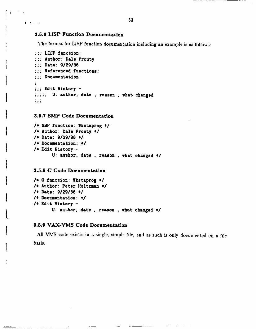
i '
i I
I I I I I I I 1 1 c I I
53
3.6.6 LISP Function Documentation
The format for LISP function documentation including an example is as follows:
;;; LISP function: ;;; Author: Dale Prouty ;;; Date: 9/29/86 ;;; Referenced functions: ;;; Documentation:
;;; Edit Hietoxy - ..... ..... U: ruthor, date , reason . what changed . . . ... 3.6.7 SMP Code Documentation
/* /* /* /* /*
SMP function: Wkstaprag */ Author: Dale Prouty */ Date: 9/29/86 */ Documentation: */ Edit History -
U: author, data . reason . what changed */
3.6.8 C Code Documentation
/* C function: Wktetaprog */ /* Author: Peter Holtrmnn */ /* Date: 9/29/86 */ /* Documentation: */ /* Edit History -
U: author. date . reateon . what changed */
3.5.9 VAX-VMS Code Documentation
All W S code existis in a single, simple file, and as such is only documented cn a file
basis.

'
# 8 0 ,
54
4. Phase 11 Recommendations Phase II should enhance the current workstation functionality and add software
development aids based on AI technology (rulebased and objectoriented programming)
where AI can overcome limitations of current software methodologies, 8s mentioned in
the introduction.
Several specific areas where an AI based approach may benefit software development
include:
0 domain specific expertise - its acquisition, storage, representation, and reuse,
0 transformational implementation of designs in Fortran,
0 significantly enhanced interactive classifier or cataloguer of library information, and
0 capturing of design and implementation history.
The domain expertise is the cornerstone of expert systems. A method of reusing this
engineering expertise should be encompassed in Phase 11, as well as automation of the
knowledge acquisition process. The designs developed with this expert assistance should
then more readily and efficiently be implemented in low level procedural code. The cataloguing of designs should significantly improved so that the knowledge regarding the
design is reusable, especially the design decisions made by the engineer.
Other significant accomplishments that should be addressed in Phase II include:
0 support for execution and analysis of graphical specifications, including interacitve simulation capability, and
0 autormted documentation of designs.
It. is desirable for the user to be able to test designs direct,ly from the interface in a
modular and interactive fahion, in a way similar to that of the interactive use of LISP. Finally, the automated recording of documentation is a process to be heralded for
removing the biggest existing headache for software developers and certainly deserves a
place in m y workstation that seriously addresses developers needs.

I" I I I I I I I t I I I 1 1 I I
55
A. Phase I Source Code Listing The source code listing is over
supplied to Robert Savely, NASA
500 pages long. A single copy has
JSC. Also, a tape has been . supplied for a Symbolics computer.
for any associated information.
Please refer to Mr. Savely