PERMISSIBLE RESIDUAL UNBALANCE - …transmiddleeast.com/Pictures/DYNAIR/DUBAI/Dynair/Technical...
5
An unbalanced rotor will cause vibration and stress in the rotor itself and in its supporting structure. Balancing of the rotor is therefore necessary to accomplished one or more of the following : (a) Increase bearing life (b) Minimize vibration (c) Minimize audible and signal noises (d) Minimize operating stresses (e) Minimize operator annoyance and fatigue (f) Minimize power losses (g) Increase quality of product (h) Satisfy customers Unbalance in just one rotating component of an assembly may cause the entire assembly to vibrate. This induced vibration in turn may cause excessive wear in bearings, bushings, shafts, spindles, gears, etc., substantially reducing their service life. Vibrations set up highly undesirable alternating stresses in structural supports and frames which may eventually lead to their complete failure. Performance is decreased because of the absorption energy by the supporting structure. Vibrations may be transmitted through the floor to adjacent machinery and seriously impair its accuracy or proper functioning. Purpose of Balancer A balancer or balancing machine is necessary to detect, locate, and measure unbalance. The data furnished by the balancer permits changing the mass distribution of a rotor, which, when done accurately, will balance the rotor. Balance is a zero quantity, and therefore is detected by observing an absence of unbalance, never balance. Definition Unbalance is the uneven distribution of weight in the rotors (wheel, shaft or pulley etc.) Eccentricity means not having the same center or axis of rotation. PERMISSIBLE RESIDUAL UNBALANCE 71
Transcript of PERMISSIBLE RESIDUAL UNBALANCE - …transmiddleeast.com/Pictures/DYNAIR/DUBAI/Dynair/Technical...

An unbalanced rotor will cause vibration and stress in the rotor itself and in its supporting structure. Balancing of the rotor is therefore necessary to accomplished one or more of the following :
(a) Increase bearing life(b) Minimize vibration(c) Minimize audible and signal noises(d) Minimize operating stresses(e) Minimize operator annoyance and fatigue(f) Minimize power losses(g) Increase quality of product(h) Satisfy customers
Unbalance in just one rotating component of an assembly may cause the entire assembly to vibrate. This induced vibration in turn may cause excessive wear in bearings, bushings, shafts, spindles, gears, etc., substantially reducing their service life.
Vibrations set up highly undesirable alternating stresses in structural supports and frames which may eventually lead to their complete failure. Performance is decreased because of the absorption energy by the supporting structure.
Vibrations may be transmitted through the floor to adjacent machinery and seriously impair its accuracy or proper functioning.
Purpose of BalancerA balancer or balancing machine is necessary to detect, locate, and measure unbalance. The data furnished by the balancer permits changing the mass distribution of a rotor, which, when done accurately, will balance the rotor.
Balance is a zero quantity, and therefore is detected by observing an absence of unbalance, never balance.
DefinitionUnbalance is the uneven distribution of weight in the rotors (wheel, shaft or pulley etc.)
Eccentricity means not having the same center or axis of rotation.
PERMISSIBLE RESIDUAL UNBALANCE
71
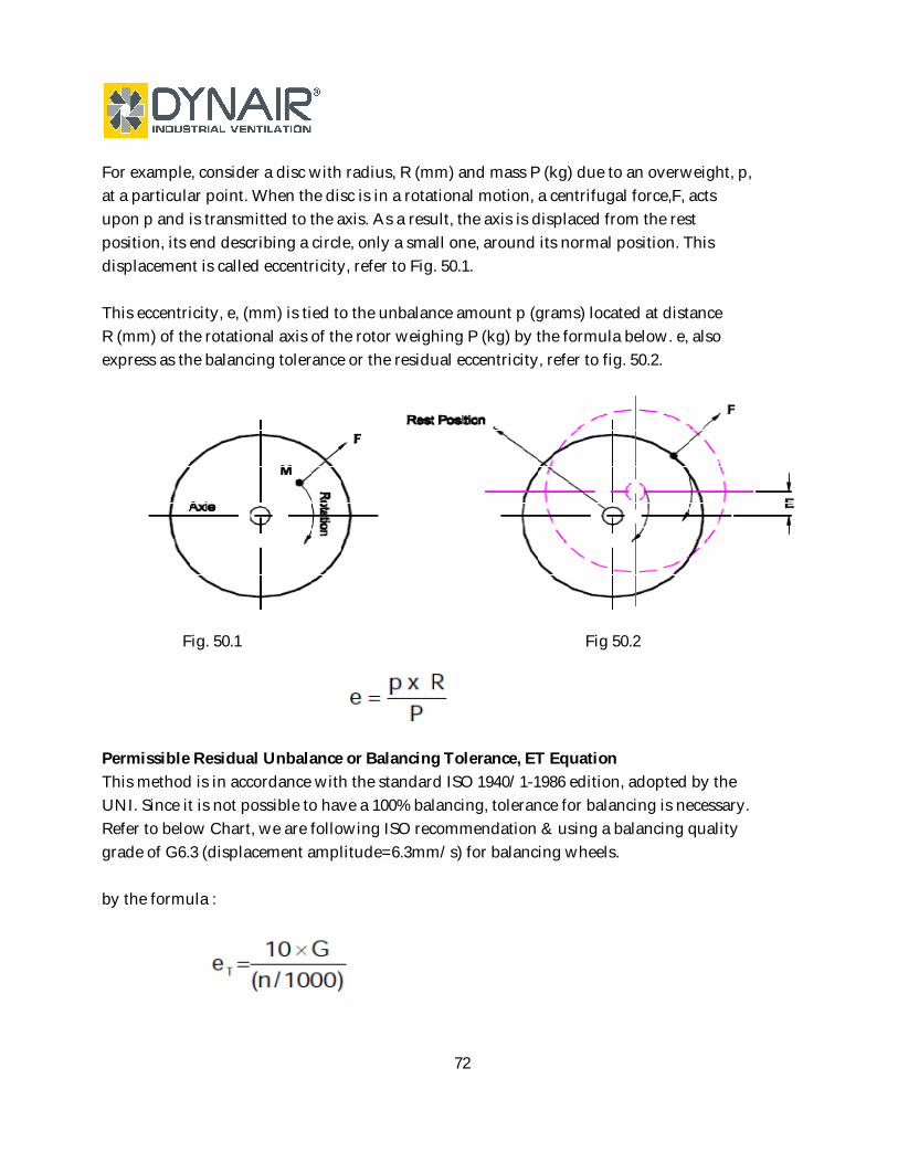
For example, consider a disc with radius, R (mm) and mass P (kg) due to an overweight, p, at a particular point. When the disc is in a rotational motion, a centrifugal force,F, acts upon p and is transmitted to the axis. As a result, the axis is displaced from the rest position, its end describing a circle, only a small one, around its normal position. This displacement is called eccentricity, refer to Fig. 50.1.
This eccentricity, e, (mm) is tied to the unbalance amount p (grams) located at distance R (mm) of the rotational axis of the rotor weighing P (kg) by the formula below. e, also express as the balancing tolerance or the residual eccentricity, refer to fig. 50.2.
Fig. 50.1 Fig 50.2
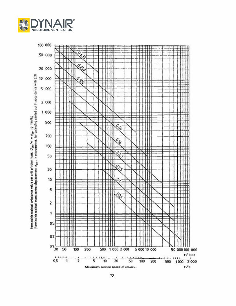
Permissible Residual Unbalance or Balancing Tolerance, ET EquationThis method is in accordance with the standard ISO 1940/1-1986 edition, adopted by the UNI. Since it is not possible to have a 100% balancing, tolerance for balancing is necessary. Refer to below Chart, we are following ISO recommendation & using a balancing quality grade of G6.3 (displacement amplitude=6.3mm/s) for balancing wheels.
by the formula :
72
73

Table 1 Balance quality grades for various groups of representative rigid rotors(From ISO 1940/1)
BalanceQualityGrade
Product of theRelationship (eper x v) (1) (2)
mm/s
Rotor Types - General Examples
G 4 000
G 1 600
G 630
G 250
G 100
G 40
G 16
G 6.3
G 2.5
G 1
G 0.4
4 000
1 600
630
250
100
40
16
6.3
2.5
1
0.4
Crankshaft/drives(3) of rigidly mounted slow marine diesel engines with uneven number of cylinders(4)
Crankshaft/drives of rigidly mounted large two-cycle engines
Crankshaft/drives of rigidly mounted large four-cycle enginesCrankshaft/drives of elastically mounted marine diesel engines
Crankshaft/drives of rigidly mounted fast four-cylinder diesel engines(4)
Crankshaft/drives of fast diesel engines with six or more cylinders(4)
Complete engines (gasoline or diesel) for cars, trucks and locomotives(5)
Car wheels, wheel rims, wheel sets, drive shaftsCrankshaft/drives of elastically mounted fast four-cycle engines with six or more cylinders(4)
Crankshaft/drives of engines of cars, trucks and locomotives
Drive shafts (propeller shafts, cardan shafts) with special requirementsParts of crushing machinesParts of agricultural machineryIndividual components of engines (gasoline or diesel) for cars, trucks and locomotivesCrankshaft/drives of engines with six or more cylinders under special requirements
Parts of process plant machinesMarine main turbine gears (merchant service)Centrifuge drumsPaper machinery rolls; print rollsFans AssembledAssembled aircraft gas turbine rotorsFlywheelsPump impellersMachine-tool and general machinery partsMedium and large electric armatures (of electric motors having at least 80 mm shaft height) without
special requirementsSmall electric armatures, often mass produced, in vibration insensitive applications and/or with
vibration-isolating mountingsIndividual components of engines under special requirements
Gas and steam turbines, including marine main turbines (merchant service)Rigid turbo-generator rotorsComputer memory drums and discs
Turbo-compressorsMachine-tool drivesMedium and large electric armatures with special requirementsSmall electric armatures not qualifying for one or both of the conditions specified for small electric
armatures of balance quality grade G 6.3Turbine-driven pumps
Tape recorder and phonograph (gramophone) drivesGrinding-machine drivesSmall electric armatures with special requirements
Spindles, discs and armatures of precision grindersGyroscopes
1) v = 2πn/60 ≈ n/10, if n is measured in revolutions per minute and v in radians per second.2) For allocating the permissible residual unbalance to correction planes, refer to "AIIocation of Uper to correction planes."3) A crankshaft/drive is an assembly which includes a crankshaft, flywheel, clutch, pulley, vibration damper, rotating portion of connecting rod, etc.4) For the purposes of this part of ISO 1940/1, slow diesel engines are those with a piston velocity of less than 9 m/s; fast diesel engines are those
with a piston velocity of greater than 9 m/s.5) In complete engines, the rotor mass comprises the sum of all masses belonging to the crankshaft/drive described in note 3 above.
Blower- Impeller Wheels Fans